

SONY KV-29FS140 Diagram
SERVICE MANUAL BX1
CHASSIS
MODEL COMMANDER DEST. CHASSIS NO.
KV-21CL5K
RM-W100 OIRT SCC-U92G-A
MODEL COMMANDER DEST. CHASSIS NO.
TRINITR ON
®
COLOR TV

KV-21CL5K
RM-W100
TABLE OF CONTENTS
Section Title Page
CAUTION & WARNING.......................................................3
WARNING (UK only)..........................................................3
SELF DIAGNOSTIC FUNCTION ........................................4
1. DISASSEMBLY
1-1. Rear Cover Removal................................................... 7
1-2. Speaker Block Assy Removal..................................... 7
1-3. Chassis Assy Removal ................................................ 7
1-4. Service Position .......................................................... 7
1-5. T erminal Brack et Remov al ......................................... 7
1-6. A Board Removal ....................................................... 7
1-7. Picture Tube Removal................................................. 8
2. SET-UP ADJUSTMENTS
2-1. Beam Landing ............................................................. 9
2-2. Convergence.............................................................. 10
2-3. Focus Adjustment ..................................................... 12
2-4. G2 (SCREEN) Adjustment....................................... 12
2-5. White Balance Adjustment....................................... 12
Section Title Page
4. DIAGRAMS
4-1. Block Diagram .......................................................... 27
4-2. Circuit Boards Location ........................................... 28
4-3. Schematic Diagram................................................... 28
4-3-1. A Board – Processor (Block A) ..................... 29
4-3-2. A Board – Audio (Block B) ........................... 31
4-3-3. A Board – Power Supply (Block C) .............. 33
4-3-4. A Board – Deflection (Block D).................... 35
4-3-5. A Board – T uner (Block E)............................ 37
4-3-6. A Board – Jack, Scart T erminal (Block F) .... 39
4-3-7. C Board .......................................................... 41
4-4. Voltage Measurement And Waveform...................... 42
4-5. Printed Wiring Boards And Parts Location.............. 45
4-6. Semiconductors......................................................... 48
5. EXPLODED VIEWS
5-1. Chassis ...................................................................... 50
6. ELECTRICAL PARTS LIST......................................... 51
3. CIRCUIT ADJUSTMENTS
3-1. Adjustment With Commander .................................. 13
3-2. Adjustment Item T able ............................................. 14
3-3. T -Mode ...................................................................... 24
3-4. TT-Mode ................................................................... 24
3-5. T -Cyan Mode ............................................................ 24
3-6. Sub Brightness Adjustment ...................................... 25
3-7. Sub Contrast Adjustment.......................................... 25
3-8. Sub Colour Adjustment ............................................ 25
3-9. Tuner A GC Adjustment ............................................ 25
3-10. Deflection Adjustment.............................................. 26
CAUTION
SHORT CIRCUIT THE ANODE OF THE PICTURE TUBE AND THE
ANODE CAP TO THE METAL CHASSIS, CRT SHIELD, OR THE
CARBON PAINTED ON THE CRT, AFTER REMOVAL OF THE
ANODE CAP.
WARNING !!
INSTRUCTION MANUAL
ATTENTION
APRES AVOIR DECONNECTE LE CAP DE’LANODE,
COURT-CIRCUITER L’ANODE DU TUBE CATHODIQUE ET
CELUI DE L’ANODE DU CAP AU CHASSIS METALLIQUE DE
L’APPAREIL, OU AU COUCHE DE CARBONE PEINTE SUR LE
TUBE CATHODIQUE OU AU BLINDAGE DU TUBE
CATHODIQUE.
AN ISOLATION TRANSFORMER SHOULD BE USED DURING
ANY SERVICE WORK TO AVOID POSSIBLE SHOCK HAZARD
DUE TO LIVE CHASSIS, THE CHASSIS OF THIS RECEIVER IS
DIRECTLY CONNECTED TO THE POWER LINE.
SAFETY -RELA TED COMPONENT WARNING !!
!
COMPONENTS IDENTIFIED BY SHADING AND MARKED
ON
THE SCHEMATIC DIAGRAMS, EXPLODED VIEWS AND IN THE
PARTS LIST ARE CRITICAL FOR SAFE OPERATION. REPLACE
THESE COMPONENTS WITH SONY PARTS WHOSE PART
NUMBERS APPEAR AS SHOWN IN THIS MANUAL OR IN
SUPPLEMENTS PUBLISHED BY SONY.
ATTENTION !!
AFIN D’EVITER TOUT RISQUE D’ELECTROCUTION
PROVENANT D’UN CHÁSSIS SOUS TENTION, UN
TRANSFORMATEUR D’ISOLEMENT DOIT ETRE UTILISÈ LORS
DE TOUT DÈPANNAGE LE CHÁSSIS DE CE RÈCEPTEUR EST
DIRECTMENT RACCORDÈ Á L’ALIMENTATION SECTEUR.
ATTENTION AUX COMPOSANTS RELATIFS Á
LA SECURITÈ!!
LES COMPOSANTS IDENTIFIÈS PAR UNE TRAME ET PAR UNE
MARQUE
!
SUR LES SCHÈMAS DE PRINCIPE, LES VUES
EXPLOSÈES ET LES LISTES DE PIECES SONT D’UNE
IMPOR-TANCE CRITIQUE POUR LA SÈCURITÈ DU
FONCTIONNEMENT,
NE LES REMPLACER QUE PAR DES COMPSANTS SONY DONT
LE NUMÈRO DE PIÈCE EST INDIQUÈ DANS LE PRÈSENT
MANUEL OU DANS DES SUPPLÈMENTS PUBLIÈS P AR SONY .
– 2 –
CAUTION
Lead Free Soldered Boards
The circuit boards listed below (Table 1) may have been processed using Lead Free Solder. The boards are
identified by the LF logo . e.g A,C board (see example).
Board Function
A ONE CHIP PROCESSOR, DEFLECTION,
POWER SUPPL Y , AUDIO, TUNER, IF ,
JACK,SCART TERMINAL
C RGB AMP
(Table 1)
KV-21CL5K
RM-W100
example 1 (A Board) example 2 (C Board)
The servicing of these boards requires special precautions to be taken as outlined below:
1. It is strongly recommended to use Sony Approved Lead Free Solder material in order to guarantee optimal
quality of new solder joints.
2. Due to higher melting point of Lead Free Solder, the soldering iron tip temperature needs to be set to chip
(350 degree centigrade) and lead component (380 degree centigrade) for not more than 4 seconds. This requires
soldering equipment capable of accurate temperature control coupled with a good heat recovery characteristics.
WARNING
(FOR EUROPE MODEL WITH “U” (UK) ONLY)
The flexible mains lead is supplied to connected a B.S. 1363 fused plug having a fuse of 5 AMP rating. Should the
fuse need to be replaced, use a 5 AMP FUSE approved by ASTA to BS 1362, i.e one that carries the
ASA
T
mark.
IF THE PLUG SUPPLIED WITH THIS APPLIANCE IS NO T SUITABLE FOR THE OUTLET SOCKETS IN Y OUR
HOME, IT SHOULD BE CUT OFF AND APPROPRIATE PLUG FITTED. THE PLUG SEVERED FROM THE MAINS
LEAD MUST BE DESTROYED AS A PLUG WITH BARED WIRES IS DANGEROUS IF ENGAGED IN A LIVE
SOCKET.
When an alternative type of plug is used, it should be fitted with a 5 AMP FUSE, otherwise the circuit should be
protected by a 5 AMP FUSE at the distribution board.
How to replace the fuse?
Open the fuse compartment with
a screw driver blade and replace
the fuse.
– 3 –

KV-21CL5K
RM-W100
The units in this manual contain a self diagnostic function. If an error occurs, the STANDBY (1) indicator will automatically
begin to flash. A description of the self-diagnosis function is explained in the instr uction manual. The number of times the
STANDBY (1) indicator flashes translates to a probable source of the problem. If an error symptom cannot be reproduced,
the remote commander can be used to review the failure occurrence data stored in memory to reveal past problems and
how often these problems occur.
1. DIAGNOSTIC TEST INDICATORS
When an errors occurs, the STANDBY (1) indicator will flash a set number of times to indicate the possible cause of the
problem. If there is more than one error, the indicator will identify the first of the problem areas.
SELF DIAGNOSTIC FUNCTION
Result for all of the following diagnosis items are displayed on screen. No error has occured if the screen displays a “0”.
Diagnosis
Item
Description
Power does
not turn on
+B overcurrent
(OCP)*
V-Protect
No. of timer
STANDBY (1)
indicator flashes
Does not light
2 times
4 times
Self-Diagnostic
display/
Diagnosis result
–
2:0
or
2:1 ~ 255
4:0
or
4:1 ~ 255
Probable Cause
Location
• Power cord is not plugged
in.
• Fuse is burned out (F600)
A board.
• H OUT (Q805) is shorted.
(A board)
• IC751 is shorted. (C board)
• +13V is not supplied.
(A board)
• IC804 is faulty. (A board)
Detected
Symptoms
• Power does not come on.
• No power is supplied on
TV.
• AC Power supply is faulty.
• Power does not come on.
• Load on power line is
shorted.
• Has entered standby state
after horizontal raster.
• Ver tical deflection pulse is
stopped.
• Power line is shorted or
power supply is shorted.
IK (AKB)
HV Protect
* If a +B overcurrent is detected, stoppage of the vertical deflection is detected simultaneously. The symptom that is
diagnosed first by the mirco controller is displayed on the screen.
** Refer to Screen (G2) Adjustment in this manual.
5 times
8 times
5:0
or
5:1 ~ 255
8:0
or
8:1 ~ 255
• Video OUT (IC1545) is
faulty. (A board)
• IC001 is faulty. (A board)
• Screen (G2) is improperly
adjusted.**
• IC604 faulty.
• IC602 faulty.
• No raster is generated.
• CRT Cathode current
detection reference pulse
output is small.
• No power supply to CRT
ANODE.
• No RASTER is generated.
– 4 –
2. DISPLAY OF STANDBY (1) INDICATOR
KV-21CL5K
RM-W100
FLASH COUNT
Lamp ON 300ms
Lamp OFF 300ms
Diagnostic Item Flash Count*
+B overcurrent 2 times
V-Protect 4 times
IK (AKB) 5 times
HV Protect 8 times
* One flash count is not used for self-diagnosis.
Lamp OFF 3 sec
STANDBY u indicator
3. STOPPING THE
STANDBY (1) INDICATOR FLASH
Turn off the power switch on the TV main unit or unplug the power cord from the outlet to stop the STANDBY (1)
indicator from flashing.
4. SELF-DIAGNOSTIC SCREEN DISPLAY
For errors with symptoms such as "power sometimes shuts off" or "screen sometimes goes off" that cannot be confirmed,
it is possible to bring up past occurrences of failure on the screen for confirmation.
[To Bring Up Screen Test]
In standby mode, press buttons on the remote commander sequentially in rapid succession as shown below:
Display
/ Channel 5 / Volume / Power / TV
˘
Note that this differs from entering the service mode (volume [+]).
The following screen will be displayed indicating the error count.
ERROR MENU
2 : 0
3 : N/A
4 : 0
5 : 1
8 : 0
101 : N/A
Numeral "0" means that no fault was detected.
Numeral "1" means the number of a fault occurrence (1 ~ 255).
– 5 –
KV-21CL5K
RM-W100
5. HANDLING OF SELF-DIAGNOSTIC SCREEN DISPLAY
Since the diagnostic results displayed on the screen are not automatically cleared, always check the self-diagnostic screen
during repairs. When you have completed the repairs, clear the result display to “0”.
Unless the result display is cleared to “0”, the self-diagnosis function will not be able to detect subsequent faults after
completion of the repairs.
[Clearing the result display]
To clear the result display to “0”, press buttons on the remote commander subsequent as shown below when the
self-diagnostic screen is being displayed.
[Quitting Self-diagnostic screen]
To quit the entire self-diagnostic screen, turn off the power switch on the remote commander or the main unit.
8 / -
6. SELF-DIANOSTIC CIRCUIT
FROM
C BOARD
IC751 PIN 5
A BOARD
FROM
Q804
COLLECTOR
A BOARD
IC001
Y/CHROMA JUNGLE
IK
32
EHTO
A BOARD
IC804
V.OUT
F.B-PLS
A BOARD
IC001
SYSTEM
SDA1
3 1384
V.GUARD
RED LED
99
122
DISPLAY
A BOARD
IC003
MEMORY
5
SDA
[+B overcurrent $OCP%] Occurs when an overcurrent on the +B(135V) line is detected by pin 32 of IC001 (A board).
If the voltage of pin 32 of IC001 (A board) is more than 4V, the unit will automatically go to
standby.
[V-PROTECT] Occurs when an absence of the vertical deflection pulse is detected by pin 13 of IC001
(A board).
[IK $AKB%] If the RGB levels* do not balance within 15 sec after the power is tur ned on, this error will be
detected by IC001 (A board). TV will stay on, but there will be 5 times LED blinking.
[HV PROTECT] Occurs when IC001 internal HV protect detects an abnormal H-Pulse (frequency) due to
improper power supply to IC001. TV cuts off high voltage power of anode CRT. No picture will
be detected. eg: IC602, IC604 go faulty.
* (Refers to the RGB levels of the AKB detection Ref pulse that detects IK.)
– 6 –
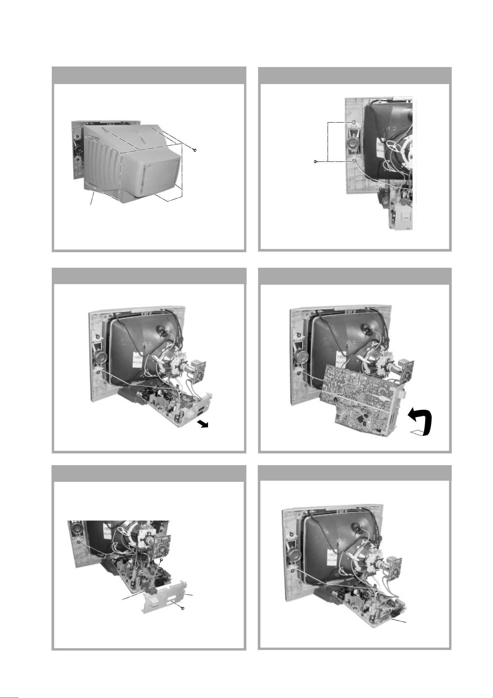
SECTION 1
DISASSEMBLY
KV-21CL5K
RM-W100
1-1. REAR COVER REMOVAL
2 Rear cover
1 Eight Screws
(PT screws)
1-2. SPEAKER BLOCK ASSY REMOVAL
Two Screws
(4 x 16)W(+)
P TAPPING
1-3. CHASSIS ASSY REMOVAL
1-4. SERVICE POSITION
1-5. TERMINAL BRACKET REMOVAL
1 One screw
(+BVTP 3x16)
3 Terminal
Bracket FBT
2 One screw
(PT screws)
bracket
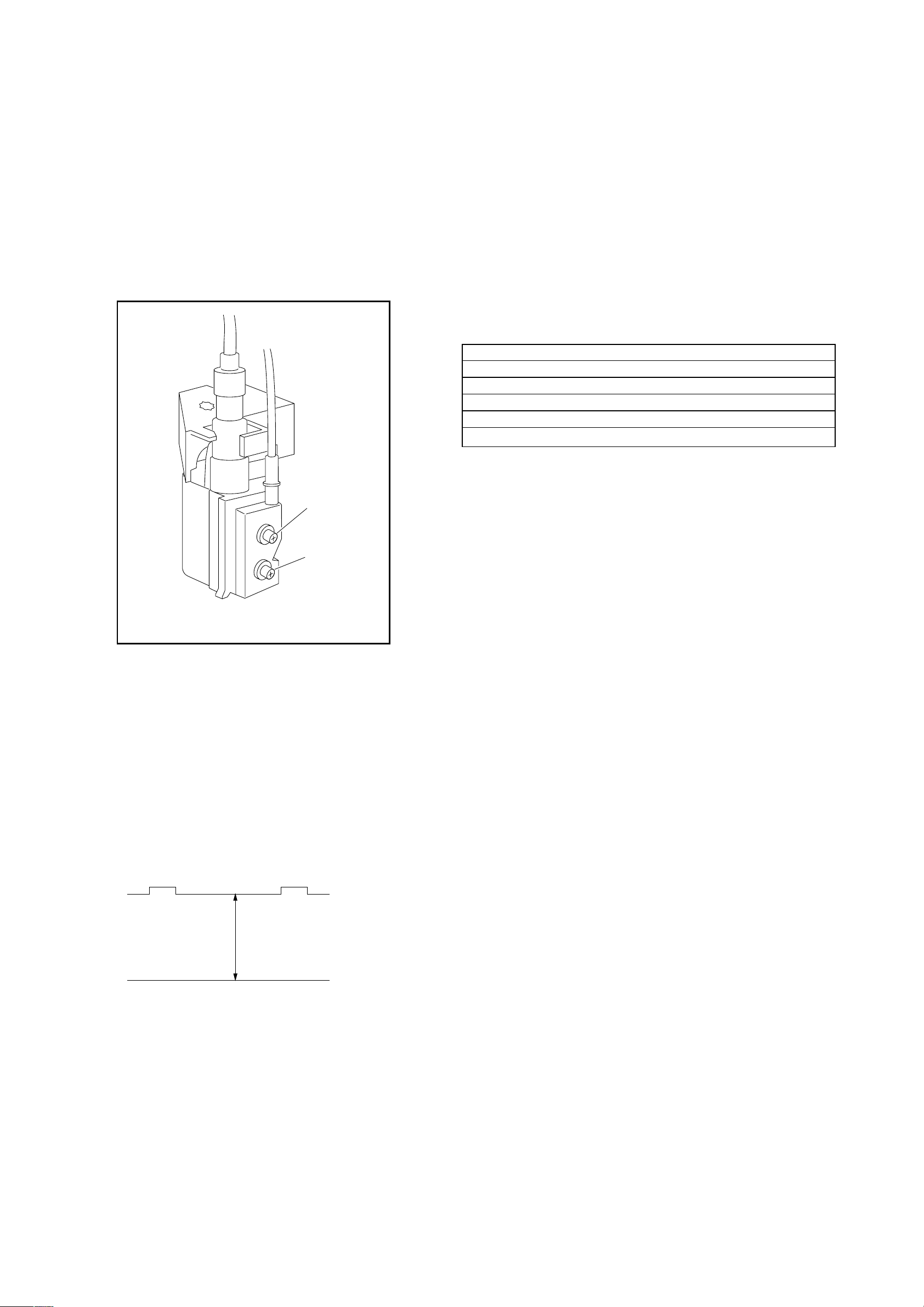
1-6. A BOARD REMOVAL
A Board
– 7 –
KV-21CL5K
c
RM-W100
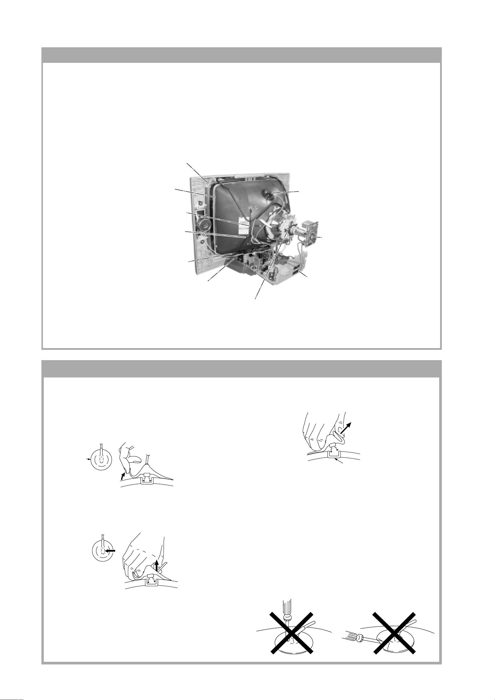
1-7. PICTURE TUBE REMOVAL
Note:
• Please make sure the TV set is not in standing position before removing necessary CRT support located on bottom
right and left.
1)Place the TV set with the CRT face down on a cushion jig.
2)Removal the rear cover.
3)Unplug all interconnecting leads from the Deflection Y oke, Degaussing Coils and CRT grounding strap.
qd unscrew — PT Screw (x4)
qs Earth Coating Assy Removal
9 Holder, DGC Removal (x2)
0 Degaussing Coil
Removal (x2)
qa Spring Tension
Removal (x1)
8 Support, CRT(21)
Removal (x2)
4 Anode Cap Removal
5 C Board Removal
7 Chassis Assy Removal
6 Loosen the Deflection Yoke
fixing screw and remove
• REMOVAL OF ANODE-CAP
Note:
• After removing the anode, short circuit the anode of the picture tube and the anode cap to the metal chassis, CRT
shield or carbon paint on the CRT.
• REMOVING PROCEDURES
a
a
1 Turn up one side of the rubber cap in the direction
indicated by the arrow a.
b
b
the anode button, the anode-cap can be removed by
turning up the rubber cap and pulling it up in the
direction of the arrow c.
• HOW TO HANDLE AN ANODE-CAP
1 Do not damage the surface of anode-caps with
sharp shaped objects.
2 Do not press the rubber too hard so as not to
damage the inside of anode-cap.
A metal fitting called the shatter-hook terminal is
built into the rubber.
3 Do not turn the foot of rubber over too hard.
The shatter-hook terminal will stick out or damage
the rubber.
anode button
2 Using a thumb pull up the rubber cap firmly in the di-
rection indicated by the arr ow b.
3 When one side of the rubber cap is separated from
– 8 –
SECTION 2
SET-UP ADJUSTMENTS
KV-21CL5K
RM-W100
• The following adjustments should be made when a
complete realignment is required or a new picture tube is
installed.
Perform the adjustments in the following order :
1. Beam Landing
2. Convergence
3. Focus
Set the controls as follows unless otherwise noted:
VIDEO MODE.................................................. STANDARD
PICTURE CONTROL .......................................... NORMAL
BRIGHTNESS CONTROL.................................... NORMAL
4. Screen (G2)
5. White Balance
Note : Test Equipment Required.
1. Pattern Generator
2. Degausser
3. DC Power Supply
4. Digital Multimeter
5. Oscilloscope
○○○○○○○○○○○○○○○○○○○○○○○○○○○○○○○○○○○○○○○○○○○○○○○○○○○○○○○○○○○○○○○
Preparation:
In order to reduce the influence of geomagnetism on the
7. If the beam does not land correctly in all the corners,
use a magnet to correct if. (see figure 2-1-3)
set's picture tube, face it east or west. Switch on the set's
power and degauss with the degausser.
Purity control
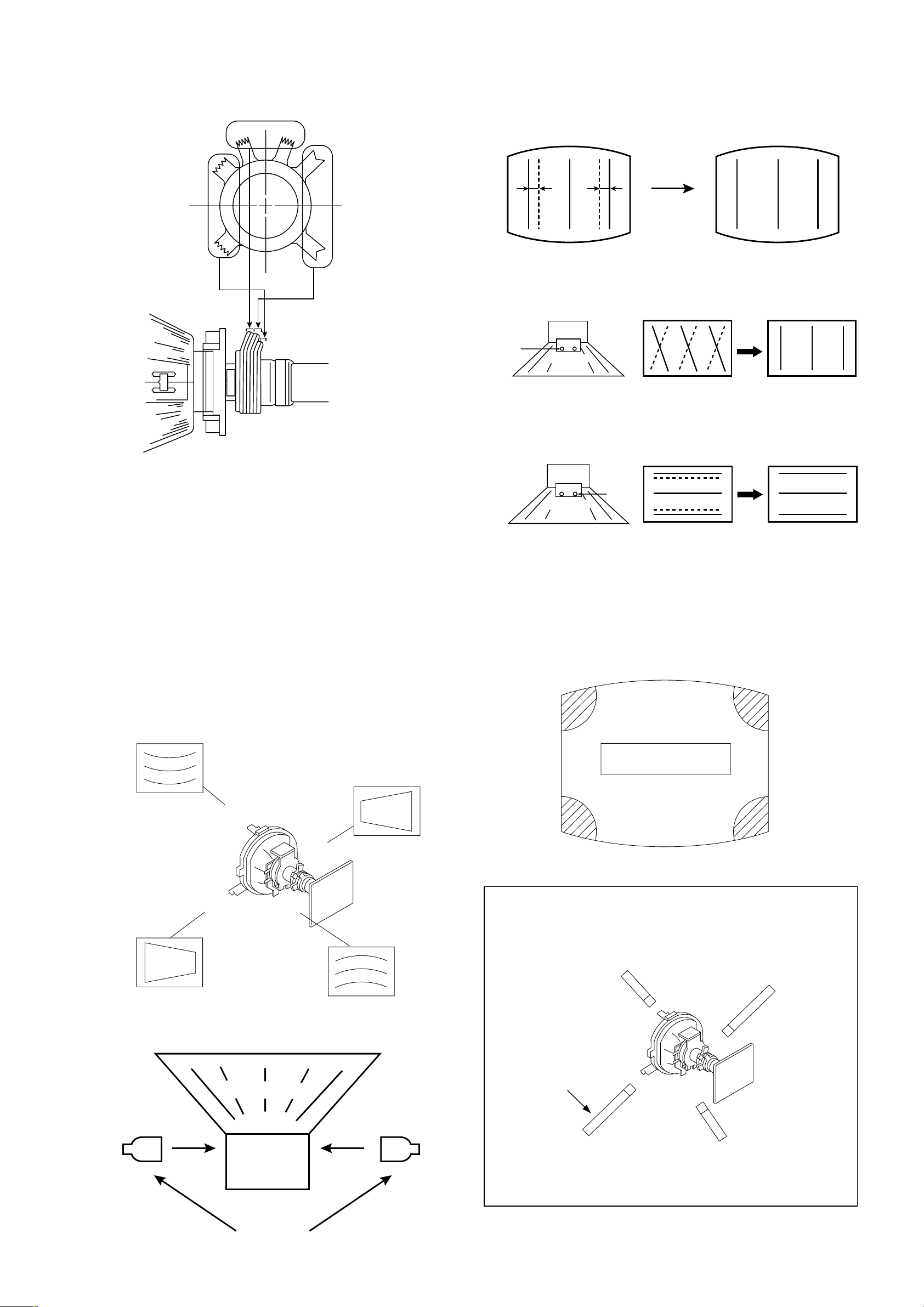
2-1. BEAM LANDING
Picture Mode : LIVE
corrects this area.
b
a
Disk magnets or rotatable
disk magnets correct these
areas (a-d).
1. Input a white signal with the pattern generator.
Set the contrast and brightness to normal.
2. Set the pattern generator raster signal to a green raster.
c
d
3. Move the deflection yoke to the rear and adjust with the
purity control so that the green is at the centre and the
blue and red take up equally sized areas on each side
Deflection yoke positioning
corrects these areas.
of the screen. (see figure 2-1 and figure 2-1-1)
Purity control
Figure 2-1 Figure 2-1-1
4. Move the deflection yoke forward and adjust so that the
entire screen is green. (see figure 2-1-2)
b
c
a
d
Figure 2-1-3
Caution:
High voltages are present on the Deflection yoke
terminals. Take care when handling the deflection yoke
whilst carrying out adjustments.
Blue
Red
Green
Figure 2-1-2
5. Switch the raster signal to blue, then red and verify the
condition.
6. When the position of deflection yoke have been
decided, fasten the deflection yoke with the screws and
DY spacers.
– 9 –
KV-21CL5K
BGR
A
RGB
B
RM-W100
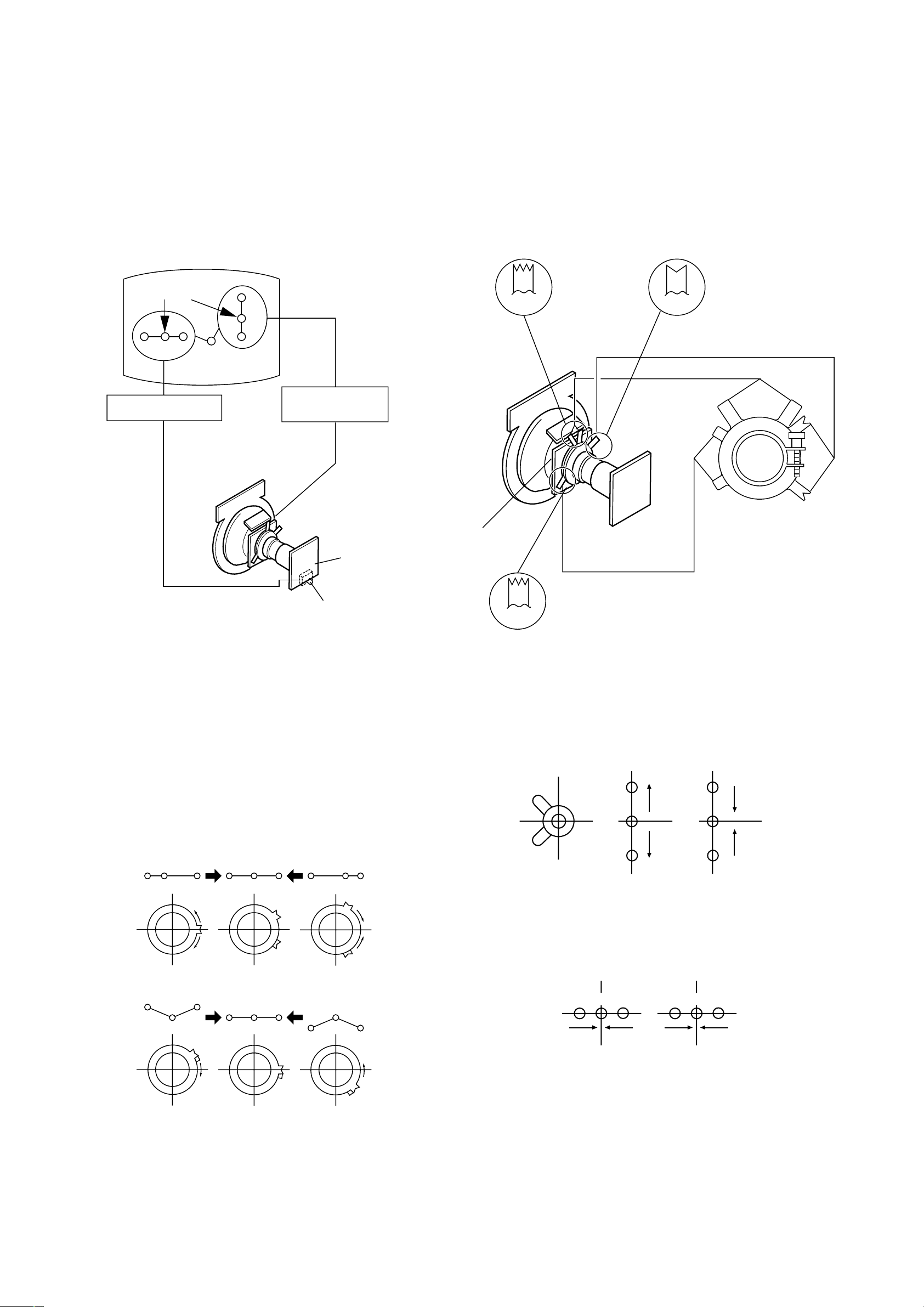
2-2. CONVERGENCE
Preparation:
• Before starting this adjustment, adjust the focus,
horizontal size and vertical size.
• Receive dot/hatch signal.
• Picture Mode : MOVIE
(A) Horizontal and Vertical Static Convergence
Centre dot
R G B
H. STAT VR
R
G
B
V. STAT
Magnet
4. If the H.STAT variable resistor cannot bring the red,
green and blue dots together at the centre of the
screen, adjust the horizontal convergence with the H.
STAT var iable resistor and the V.STAT magnet in the
manner given below.
(In this case, the H.STAT variable resistor and the
V.STAT magnet influence each other, so be sure to
perform adjustments while tracking.)
BMCPurity
BMC (Hexapole)
Purity
C Board
RV750
1. (Moving vertically), adjust the V.STAT magnet so that
the red, green and blue dots are on top of each other at
ther centre of the screen.
2. (Moving horizontally), adjust the H.STAT VR control so
that the red, green and blue dots are on top of each
other at the centre of the screen.
3. BMC (Hexapole)Magnet
If the red, green and blue dots are not balanced or
aligned then use the BMC magnet to adjust in the
manner described below.
DY pocket
V.STAT
V.STAT
Operation of V.STAT magnet.
If the V.STAT is moved in the "A" and "B" arrows, the red,
green and blue dots moves as shown below.
AB
B
G
B
G
BG R R G B R GB
RB
G
RG
GB
RB
R
R
Moved RV750 H.STAT the red, green and blue dots move
as shown below.
– 10 –
KV-21CL5K
RM-W100
5. Layout of each control.
V.STAT
Purity
BMC (Hexapole)
H-TILT correction can be performed by adding a TLH
correction assembly to the Deflection Y oke.
8. YCH Adjustment
YCH VR
Deflection Yoke
6. Geometr y Adjustment.
Preparation:
Before starting this adjustment, adjust the horizontal and
vertical static convergence.
a) Remove the deflection yoke spacer.
b) Tilt the deflection yoke as indicated in the figure below
and optimise the geometry.
Tilting the DY up and down will balance the upper and
lower pin adjustment.
Tilting the DY left and right will balance the H-Trap
adjustment.
c) Re-install the deflection yoke spacer.
9. TLV Adjustment
TLV VR
Deflection Yoke
10.Screen Corner Convergence.
If you are unable to adjust the corner convergence
properly, this can be corrected with the use of Piece
A(90) Conv. Correct.
ba
7. H-TILT Adjustment
,
,
,
,
Tilt Direction
Deflection Yoke
a-d : screen-corner
misconvergence
cd
,
Install the Piece A(90) Conv. Correct
assembly for the area that needs correcting.
a
b
Piece A(90) Conv. Correct
4-094-690-01
TLH pieces
– 11 –
d
Convergence adjustment with
Piece A(90) Conv. Correct
c
KV-21CL5K
RM-W100
2-3. FOCUS ADJUSTMENT
1. Receive digital monoscope pattern.
2. Set Picture Mode to PERSONAL.
3. Adjust focus VR to obtain the best focus at the centre of
the screen.
4. Change the receiving signal to white pattern and blue
back.
5. Confirm magenta ring is not noticeable. In case
magenta is very obvious, adjust the focus VR to take
balance of magenta ring and focus.
2-5. WHITE BALANCE ADJUSTMENT
1. Enter into Service Menu.
2. Input white pattern signal.
3. Set picture to PERSONAL mode.
4. Select WHBL "RDRV" and fix the value to 25 hex.
5. Adjust WHBL "GDRV" and "BDRV" and adjust the data
for best white balance in highlight condition.
6. Adjust WHBL "BKOR" and "BKOG" and adjust the data
for best white balance cut-off condition.
7. Set the offset settings for LIVE and GAME mode as
stated in the table 1 below:-
OFFSET TABLE (Table 1)
Live T Personal T Game
Adjusted value +2 BKOR (adjusted) Adjusted value
Adjusted value -3 BKOG (adjusted) Adjusted value
25hex RDRV (25hex) 25hex
Adjusted value +2 GDRV (adjusted) Adjusted value -2
Adjusted value +4 BDRV (adjusted) Adjusted value -6
FOCUS
SCREEN
FLYBACK TRANSFORMER (T801)
2-4. G2(SCREEN) ADJUSTMENT
1. Input a dot signal from the pattern generator.
2. Set the Picture, Brightness and Colour to minimum.
3. Apply 167V DC from an external power supply to the
R,G and B cathodes of the CRT.
4. Adjust brightness to obtain cathode value to value
below.
5. Whilst watching the picture, adjust the G2 control
[SCREEN] located on the Flyback Transformer to the
point just before the flyback return lines disappear.
Cathode setting voltage:
167 V ± 2 (VDC) — 21"
– 12 –
SECTION 3
CIRCUIT ADJUSTMENTS
3-1. ADJUSTMENT WITH COMMANDER
Service adjustment to this model can be performed using the supplied remote commander RM-W100.
a. ENTERING SERVICE MODE
With the unit on standby, press the following sequence of buttons on the remote commander.
/ Display / Channel 5 / Volume [+] / Power / TV
'TT – –'will appear in the upper right cor ner of the screen.
KV-21CL5K
RM-W100
Other status information will also be displayed.
b. Press 'MENU' on the remote commander to obtain service menu on the screen.
GEOM
WHBL
SADJ
YC
SYNC
PICT
SW
VIF
c. The screen only displays 8 items at one time. To move to the corresponding item use the up
the remote commander.
d. Press the right
/ left button or ENTER button on the remote commander to enter into the required item.
Item
Name
Range Data
down buttons on
HPOS
HPAR
e. The screen only display 12 items at one time. To move to the corresponding item use the up
the remote commander.
f. Press right
g. Press the 'MENU' button on the remote commander to quit from Service Menu. Screen will still display 'TT – –'. To exit
from 'TT – –' menu, press 0 twice, 'TEST', 'TV' or switch the TV into standby mode.
Note:
• After carrying out the ser vice adjustments, to prevent the customer accessing the 'Service Menu' switch the TV set
OFF and then ON.
to increase or left to decrease the data.
52(0,63)
40(0,63)
down buttons on
– 13 –
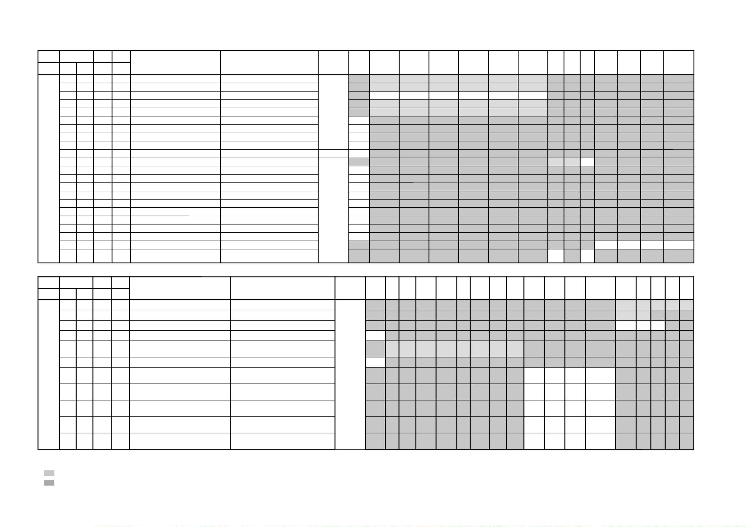
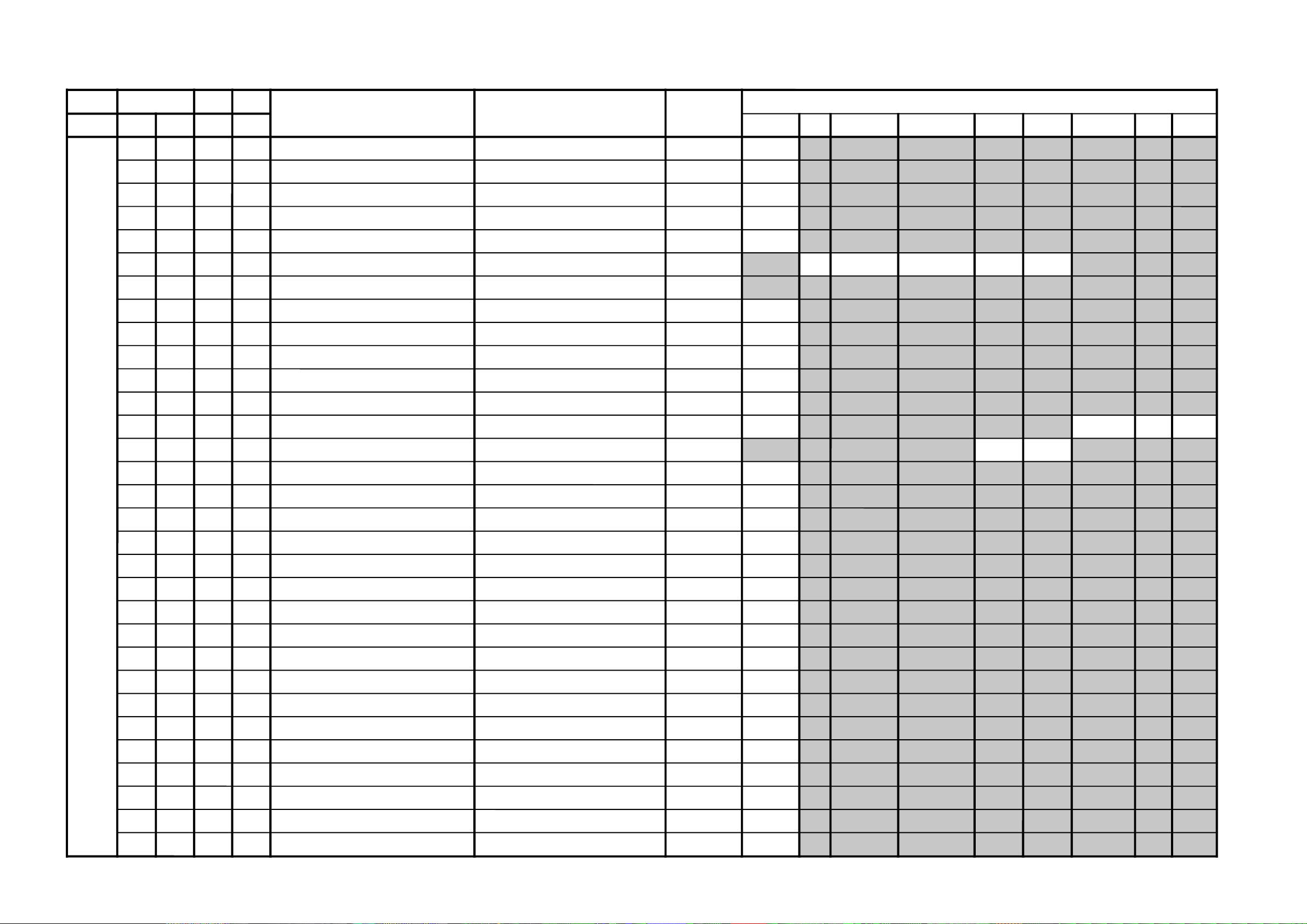
JVTytilanoitcnuFlaitinIegnaR
noitcnuFetoN&elbaTemaNeciveDnommoC050605w06w
yrogetaCoNemaNceDceD
MOEG
000SOPH130360)SH(tfihSlatnoziroH )BGRNPJ+(06w/05w/06/05
rossecorP-VT
13
13
13
13
100RAPH130360margolellaraPlatnoziroH06w/05w/06/05
13
13
13
13
200WOBH130360woBlatnoziroH06w/05w/06/05
13
13
13
13
300NILV130360ytiraeniLlacitreV06w/05w/06/05
13
13
13
13
400RCSV130360llorcSlacitreV06w/05w/06/05
13
13
13
13
500ZISH130360)WE(htdiWWE )BGRNPJ+(06w/05w/06/05
13
13
13
13
600WPWE130360)WP(htdiW/alobaraPWE06w/05w/06/05
13
13
13
13
700POCU710360alobaraPrenroCreppUWE06w/05w/06/05
71
71
71
71
800POCL710360alobaraPrenroCrewoLWE06w/05w/06/05
71
71
71
71
900ZTWE130360muizeparTWE06w/05w/06/05
13
13
13
13
010PLSV130360)SV(epolSlacitreV06w/05w/06/05
13
13
13
13
110ZISV510360edutilpmAlacitreV06w/05w/06/05
51
51
51
51
210ROCS410360)CS(noitcerroC-S06w/05w/06/05
41
41
41
41
310SOPV130360)HSV(tfihSlacitreV06w/05w/06/05
13
13
13
13
410LBH000100edoMgniknalBBGR06w/05w/06/05
10101010
510FBW700510)FBW(gniknalBediWfognimiT06w/05w/06/05
90909090
610RBW700510)RBW(gniknalBediWfognimiT06w/05w/06/05
01010101
710LBS000100gniknalBecivreSenon00
810YPOC000100aeraMVNzH06/05llaotatadOEGehtypoCenon00
3-2. ADJUSTMENT ITEM TABLE
KV-21CL5K
RM-W100
– 14 –
•
•
shaded items are adjustable data.
no data.
– 15 –
JVTytilanoitcnuFlaitinIegnaR
noitcnuFetoN&elbaTemaNeciveDnommoCeviL
)rehtoLOOC(
EMAG
)rehtoMRAW(
/EIVOM
LANOSREP
LARTUEN(
)rehto
EVIL
)BGRLOOC(
EMAG
)BGRMRAW(
/EIVOM
LANOSREP
LARTUEN(
)BGR
rehtOBGRVUYedomciP
0
)EVIL(
edomciP
1
)EIVOM(
edomciP
2
)EMAG(
edomciP
3
)LANOSREP(
yrogetaCoNemaNceDceD
LBHW000ROKB130360RtesffOleveLkcalB )srehtO/BGR/VU(*)lamroN/WOL/HGIH(pmetlocrossecorP-VT
13
13
13
13
13
13
100GOKB130360GtesffOleveLkcalB )srehtO/BGR/VU(*)lamroN/WOL/HGIH(pmetloc
13
13
13
13
13
13
200VRDR730360RtnioPetihW )srehtO/BGR/VU(*)lamroN/WOL/HGIH(pmetloc
737373737373
300VRDG730360GtnioPetihW )srehtO/BGR/VU(*)lamroN/WOL/HGIH(pmetloc
73
73
73
73
73
73
400VRDB730360BtnioPetihW )srehtO/BGR/VU(*)lamroN/WOL/HGIH(pmetloc
73
73
73
73
73
73
500GPL000100teserPniaGBGR enon00
600RGP130721)RGP(RniaGteserP enon54
700GGP130721)GGP(GniaGteserP enon54
800BGP130721)BGP(BniaGteserP enon54
900FONG000510tesffOniaGteserP enonpoolCCC80
010TRBS130360ssenthgirB-buS VUY/BGR/srehtO
83
4300
110ORBS000300)ciPtnegilletnI(tesffOssenthgirB-buS enon00
210LGE000100metsySCCCpooLniaGelbanE enon00
310LGS000300metsySCCCnitnerruChgiHfonoitceleS enon00
410BKA000100noitazilibatStnerruCkcalB enon00
510SBC000100gnitimiLtnerruCmaeBfoecneuqeSlortnoC enon00
610BBGR000300gniknalBBGR enon00
710GBLB000100tuptuOneerG&eulBfogniknalB enon00
810BFO000100eulBtesffOleveLkcalB enon00
910RBSN000510tesffOssenthgirBdradnatS-noN enon00
020PBW000300)woL:3,2,lamroN:1,hgiH:0(gnittespmeTroloC edoMerutciP
00102010
120VUO000300slangistupnIVUnolortnoCtesffO
)napaJdnaSUrofylno(
VUY/srehtO
00
00
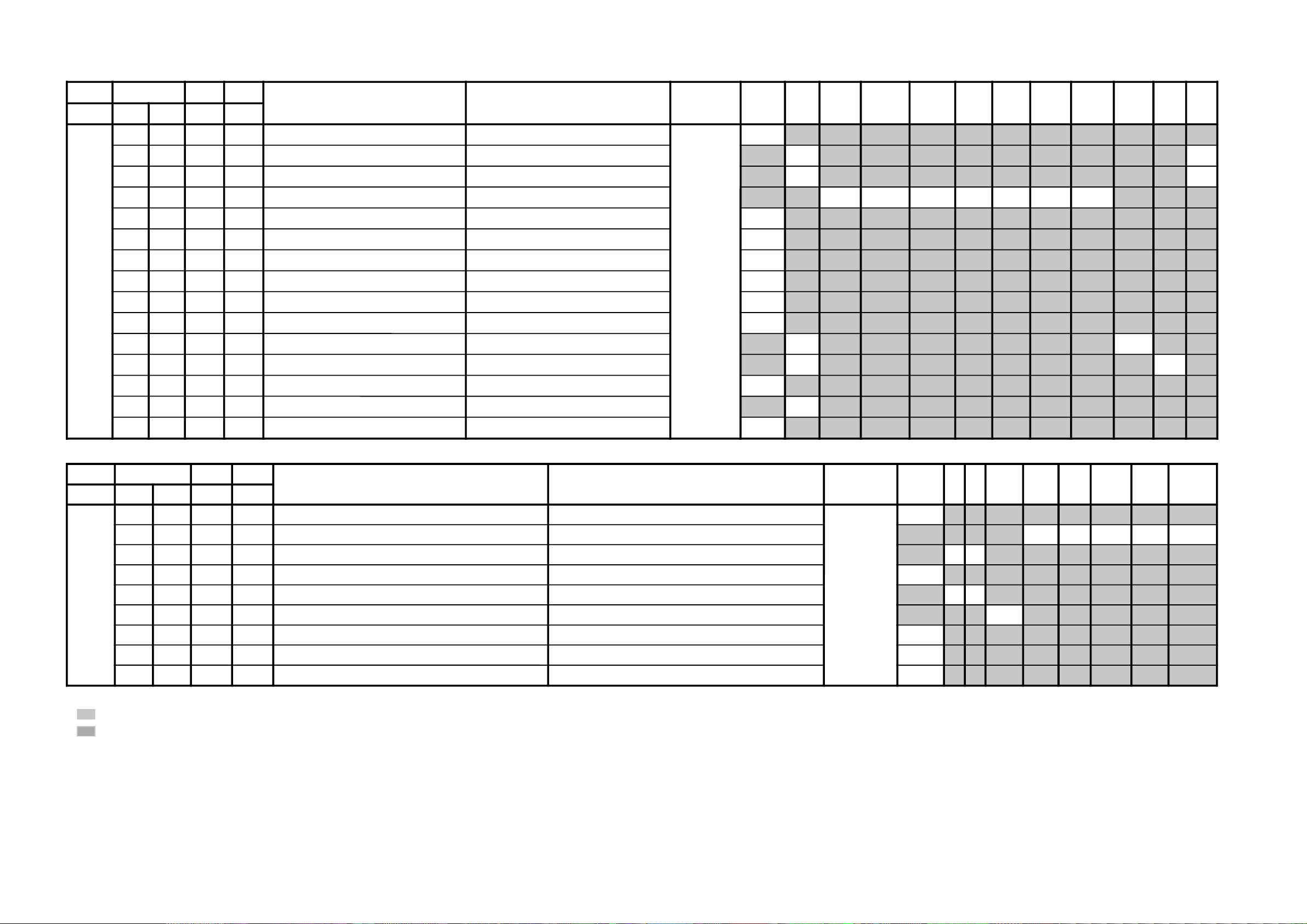
JVTytilanoitcnuFlaitinIegnaR
noitcnuFetoN&elbaTemaNeciveDnommoClap05
)VT(
lap05
)oediV(
maces05
)VT(
maces05
)oediv(
VT06oediV06BGR05BGR06edomciP
0
)EVIL(
edomciP
1
)EIVOM(
edomciP
2
)EMAG(
edomciP
3
)LANOSREP(
PI-VT
NO
oediVBGRVT
ediW
oediV
ediW
yrogetaCoNemaNceDceD
JDAS000XAMP360360mumixaMerutciP )BGRNPJ+(>ediW/lamroN</)ediW/lamroN(*)oediV/VT(rossecorP-VT
43
43
62
62
100EUHS700510euH-buS oediV/VT
70
80
200PHSS510360ssenprahS-buS )BGRNPJ+(VUY/oediV/VT
428351
300OHSS000300)ciPtnegilletnI(tesffOssenprahS-buS enon
30
400LOCS130360roloC-buS /)oediv(maces05/)vt(maces05/)oediv(lap05/)vt(lap05
BGR06/BGR05/VUY06/VUY05/oediv06/VT06
52
82
52
82
32
62
82
62
500OOCS000300)ciPtnegilletnI(tesffOroloC-buS enon
20
600CIP130721,)dilavni(001>;)dilav(001~0:AG[lortnoCerutciP
])dilavni(6tiberongi;)dilav(36~0:srehtO
)ataDteseRresU=lanosreP:AG(edoMerutciP
36538355
700LOC130721,)dilavni(001>;)dilav(001~0:AG[lortnoCroloC
])dilavni(6tiberongi;)dilav(36~0:srehtO
)ataDteseRresU=lanosreP:AG(edoMerutciP
83131313
800TRB130721,)dilavni(001>;)dilav(001~0:AG[lortnoCssenthgirB
])dilavni(6tiberongi;)dilav(36~0:srehtO
)ataDteseRresU=lanosreP:AG(edoMerutciP
13531313
900EUH130721,)dilavni(001>;)dilav(001~0:AG[lortnoCeuH
])dilavni(6tiberongi;)dilav(36~0:srehtO
)ataDteseRresU=lanosreP:AG(edoMerutciP
13131313
010PHS130721,)dilavni(001>;)dilav(001~0:AG[lortnoCssenprahS
])dilavni(6tiberongi;)dilav(36~0:srehtO
)ataDteseRresU=lanosreP:AG(edoMerutciP
24821313
•
shaded items are adjustable data.
•
no data.
KV-21CL5K
RM-W100
KV-21CL5K
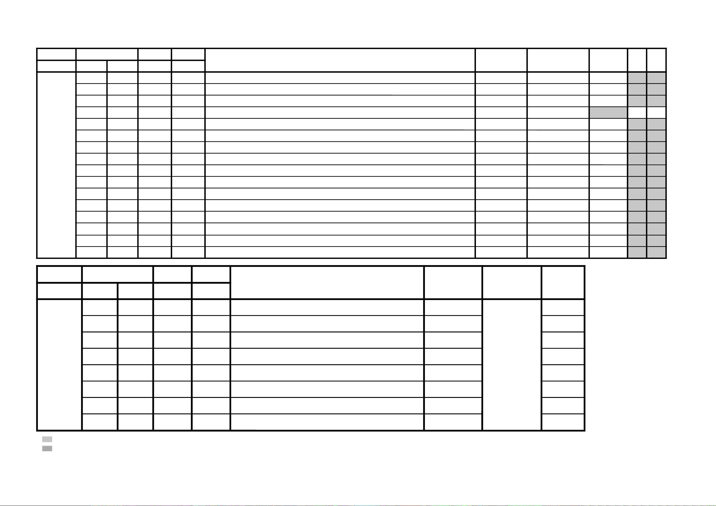
JVTytilanoitcnuFlaitinIegnaR
noitcnuF etoN&elbaTemaNeciveDnommoC0506srehtOPI-VT
NO
oediVtxeteleTPI-VT
FFO
langiSoN
yrogetaCoNemaNceDceD
CNYS000SYS000100tupnICNYSYnonoitazinorhcnyS rossecorP-VT
00
100OF000300tnatsnoCemiT1esahP
)FR(langisoNrogninuTotuA/txeteleT/oediV/FFOPIVT/NOPIVT
0030103000
200DIV000100edoMtnedIoediV
06/05
0000
300LSF000100cnySlacitreVrofleveLgnicilSdecroF
00
400LSS000100rotarapeScnySleveLgnicilS
06/05
0000
500DIVS100700noitacifitnedIoediVrofnoitceleSecruoS
srehtO/VUY
00
600FROF000300ycneuqerFdleiFdecroF
30
700KVM000100gniyeKnoisiVorcaM
10
800TCFA000300)821niP:NPJ,oruE,611niP:SU,AG(lortnoChctiwSgnimiTCFA 30
JVTytilanoitcnuFlaitinIegnaR
noitcnuFetoN&elbaTemaNeciveDnommoCsrehtO)VT(LAP)VT(CSTNMACES
)VT(
LAP
)oediV(
CSTN
)oediV(
MACES
)oediV(
TUPNI-SMACESCSTNVT
yrogetaCoNemaNceDceD
CY000QRFP000300yaleDdnaycneuqerFretneCgnikaeP rossecorP-VT
00
100APR100300toohSrevO&erPoitaR rehto/VT
20
10
200OPR200300skaePevitageN&evitisoPfooitaR rehto/VT
10
10
300YLDY210510yaleD-Y TUPNI-S/VUY+)OEDIV/VT(*)MACES/CSTN/LAP(
60606050505001
400TAMC000300xirtaM)ASU/napaJ(CSTNroMACES-LAP )BGRNPJ(
00
500LCA100100gnitimiLroloCcitamotuA
10
600BC000100ycneuqerFretneCssapdnaBamorhC )xif0:oediV*(VThtiwylnodilav
00
700OBS100300tesffOkcalBMACES
10
800ESHC100300ytivitisneStnedICSTN/LAP
20
900OLC000100retliF)lleB(ehcolCfoycneuqerFretneC
00
010PRTC000100edoMparTamorhC srehto/MACES
00
10
110SPB000100eniLyaleDdnab-esaBamorhCfossapyB srehto/CSTN
00
00
210OCF000100nOroloCdecroF
00
310TNIT130360lortnoCtniTdnaB-esaB srehtO/VUY
13
410VUT000100slangiSVUnolortnoCtniT
00
RM-W100
– 16 –
•
shaded items are adjustable data.
•
no data.
– 17 –
JVTytilanoitcnuFlaitinIegnaR
noitcnuFetoN&elbaTemaNeciveDnommoCsrehtOBGR:erutciP
eviL
VT
)eviL(
VT
)srehtO(
oediV
)eviL(
oediV
)srehtO(
pmeTroloC
)LOOC(
pmeTroloC
)srehtO(
pmeTroloC
)mraW(
pmeTroloC
)lartueN(
yrogetaCoNemaNceDceD
TCIP
000LDAC700510leveLevirDedohtaC
rossecorP-VT
20
100AFC000300edoMretliFbmoC 10
200COS200300leveLgnippilCtfoS 00
300LWP100100hctiwSgnitimiLetihWkaeP 10
400LTHW600510gnitimiLetihWkaeP 50
500MAG100100ammaG 10
600STW100300hctertSetihWdnalortnoCammaGsrehtO/eviL
00
10
700RFT000100langiSecnanimuLfooitaRrefsnarTCD )BGRNPJ+(srehtO/eviL
00
10
800ROC300300gniroC )srehto/anyD(*)oediV/VT(
20200010
900OROC000100)ciPtnegilletnI(tesffOgniroC 10
010SKB300300hctertSkcalBsrehto/BGR
2020
110SAA100100hctertSkcalBehtffohctiwSotaerAkcalB 10
210KSD000100lortnoCnikScimanyD 00
310SLB000100hctertSeulB )SREHTO/HGIH(pmetloc
1000
410SLBN000100tiucriChctertSeulBnoitarepO 00
510RRN000100noitcudeRdeRnoN )LAMRON/WOL/HGIH(pmetloc
10
0000
6102AFC000100)NPJ&SUrofylnO(noretliFbmoCdecroFenon00
JVTytilanoitcnuFlaitinIegnaR
noitcnuFetoN&elbaTemaNeciveDnommoCVToediV
yrogetaCoNemaNceDceD
WS
0002VC000100noitceleSlangiStupnI2SBVC
rossecorP-VT
00
100OVS10030084@niPISBVC/OVS/OVFIfonoitcnuFVUY/oediV/VT
1010
200LFD000100noitcetorPhsalF 00
•
shaded items are adjustable data.
•
no data.
KV-21CL5K
RM-W100
KV-21CL5K
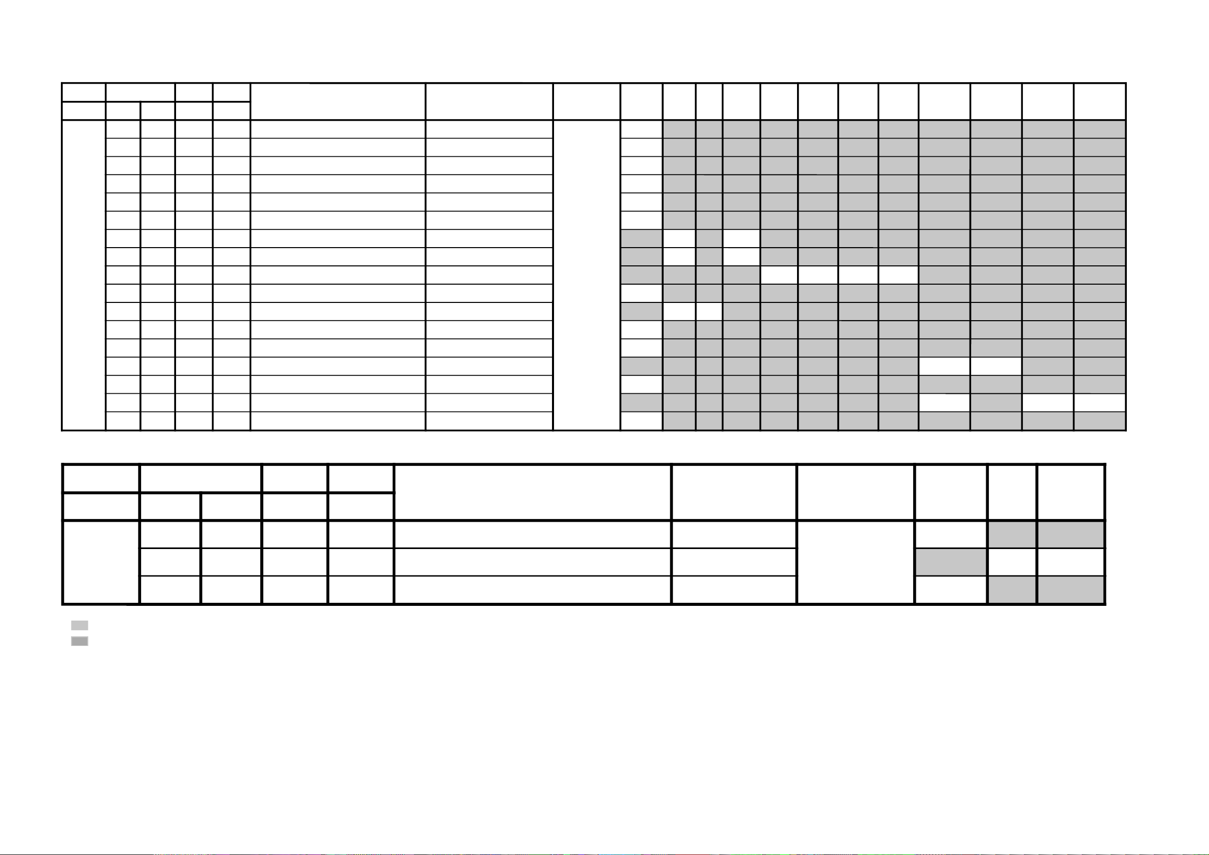
JVTytilanoitcnuFlaitinIegnaR
noitcnuFetoN&elbaTemaNeciveDnommoC
yrogetaCoNemaNceDceD
MEDS
000SWMF000300rotaludomeDMFrofnoitceleSwodniW
rossecorP-VT
20
100SSQ100100)ledoMAGtpecxe(edoMrefilpmA)SSQ(dnuoStilpSisauQ 10
200BPB000100retliFssapdnaBdnuoSfossapyB 00
300OLMA000100dnuoSMAroflangiStuptuOoiduA 00
400CVPH000100lortnoCemuloVenohPdaeH 00
JVTytilanoitcnuFlaitinIegnaR
noitcnuFetoN&elbaTemaNeciveDnommoC
yrogetaCoNemaNceDceD
FIV
000DFIO630360rotaludomeDFItesffO
rossecorP-VT
63
100TCGA130360revo-ekaTCGA
63
200MTS000100edoMgninuThcraeS 10
300DG000100langiS1SBVCnoyaleDpuorG 00
400SCGA100300deepSCGAFI 00
500IFF000100LLPFIretliFtsaF 00
600PMAO300300)metsyS'L&Lylno(edutilpmAlangiStuptuOoediV 30
700IAV000100)metsyS'L&Lylno(noitcerroCedutilpmAlangiStuptuOImetsyS 10
JVTytilanoitcnuFlaitinIegnaR
noitcnuFetoN&elbaTemaNeciveDnommoC
yrogetaCoNemaNceDceD
TXT
000VXT930360spilihProfnoitisoPlacitreVtxeteleT
redoceDtxeT
73
100DHT500721tfihSegdEevitcAcnys-HtxeteleT 50
200RBT400510ssenthgirBBGRtxeteleT 01
RM-W100
– 18 –
•
•
shaded items are adjustable data.
no data.
JVTytilanoitcnuF.tinIegnaRnoitcnuFetoN&elbaTemaNeciveD
)sserddAevalS(
)deliateD(eulaVlaitinI/sserddAMVN
yrogetaC.oNemaNceDceD nommoCffOWOW/SRSdnuorrusurToeretsIonomI)oruE(L-VTVToediV
PSDS000MVA200700edoMLVA DSS20
100VVA500510leveLecnerefeRLVA )h08(90
200LBB000510ruotnoCEBB 00
300HBB000510ssecorPEBB 00
400WLBB000510tesffOruotnoCEBB 60
500FOVS000510tesffOemuloVedoMtceffE/dnuorruS onomI/oeretsI/dnuorrusurT/)WOW/SRS(ffO
0070002000
600FOVI000700tesffOevitisoPemuloVretsaM
700FOVE000700tesffOevitageNemuloVretsaM 60
800DAL000130tsujdAleveLredoceD 60
900MAL000130tsujdAleveLonoM 50
010NAL000130tsujdAleveLmaciN 50
110SAL000130tsujdAleveLPAS 71
210AAL000130tsujdAleveLCDA oediV/Lnon-VT/L-VTI)oruEnoN(oediV/vT80
000000
310FES300700tceffEoeretS/onoMelbidercnI onomI/oeretsI
5030
410L1A000552tfeLemuloV1XUA 00
510R1A000552thgiRemuloV1XUA 00
610SAB800510tesffOssaBniaM 41
710ERT800510tesffOelberTniaM 11
8101QE800510tesffO)zH001(dnaBlennahCniaMrezilauqE 01
9102QE800510tesffO)zH003(dnaBlennahCniaMrezilauqE 10
0203QE800510tesffO)zH0001(dnaBlennahCniaMrezilauqE 00
1204QE800510tesffO)zH0003(dnaBlennahCniaMrezilauqE 01
2205QE800510tesffO)zH0008(dnaBlennahCniaMrezilauqE 00
320TCFB500700lortnoCEBBdnaBUD,EBD 00
420NECS100510lortnoCretneCD3SRS 40
520APSS000510lortnoCecapSD3SRS 10
620WHBB000510edomWOWnitesffossecorpEBB 00
720ERTS200700edomdnuorrusroftesffOelberT 10
820THBB000510edomVTnitesffOEBB 00
920AWD000000???AWD 00
030ERTT200700edoMVTnitesffOelberT 30
– 19 –
KV-21CL5K
RM-W100

KV-21CL5K
JVTytilanoitcnuF.tinIegnaRnoitcnuFetoN&elbaTemaNeciveD
)sserddAevalS(
nommoC
yrogetaC.oNemaNceDceD
CEDS000UTPM300510)CSTB(noitcetedtolipXPMrofdlohserhTreppU DSS20
100LTPM900510)CSTB(noitcetedtolipXPMrofdlohserhTrewoL 50
200UTPS300510noitcetedreirracPASrofdlohserhTreppU 80
300LTPS600510noitcetedreirracPASrofdlohserhTrewoL 51
400HT1C0001301CSfonoitcetedrofdlohserhTlamroN 00
500PA1C0001301CSfonoitcetedrofdlohserhTmargorPotuA 00
600HTPS000130PASfoetumotuarofdlohserhTesioN 00
700YHPS400510PASfoetumotuarofezissiseretsyH 30
800HTMF000130dradnats2AMFni2CSfoetumotuarofdlohserhTesioN 81
900YHMF400510dradnats2AMFni2CSfoetumotuarofezissiseretsyH 70
010HTTB000130reirracoeretsCSTBfoetumotuarofdlohserhTesioN 00
110YHTB400510oeretsCSTBfoetumotuarofezissiseretsyH 30
210HTJE000130reirracbusMFJAIEfoetumotuarofdlohserhTesioN 00
310YHJE400510reirracbusMFJAIEfoetumotuarofezissiseretsyH 40
410YLNO000100tuptuoCEDnoMACINdetalerylnoecudorpeR 00
510MAXE000100)PEDD(LdradnatsnietumotuafoesacniecruoskcabllaF 00
610TMIN000100)PEDD(etarrorretibnodnepednoitcnufetumotuaMACIN 00
710ELIN001552)PEDD(timilrorrerewolMACIN 05
810EUIN002552)PEDD(timilrorrereppuMACIN 002
910DMPE100300)PEDD(gnimmargorPysaECEDMED 10
020SDTS910130sedomSSSdnaDSArofdexelpitlumstiB 91
120AMVO100100noitpadanoitaludomrevoMF 00
220WBLF000300htdiwdnabretlifrotaludomedMA/MF 30
320DMDI000300edomSSSnideepstnediMF 00
420LAPF000100gnidocedCSTBrofycneuqefeniL 00
520TMVO100200lanimonotevitalerdlohserhtlevelnoitaludomrevO 30
620IXCD000100retrevnIlortnoCgnilacSOXCDMACIN 00
720GXCD000700niaGlortnoCgnilacSOXCDMACIN 00
820LLCD110510)L(timiLlortnoCgnilacSOXCDMACIN 00
920HLCD000130)H(timiLlortnoCgnilacSOXCDMACIN 00
030UEDI100300DTS2AnaeporuErofgnittesDOMDI 00
130RKDI100300DTSMnaeroKrofgnittesDOMDI 00
230PJDI100300DTSJAIErofgnittesDOMDI 00
RM-W100
– 20 –
– 21 –
JVTytilanoitcnuFlaitinIegnaRnoitcnuFetoN&elbaTemaNeciveDnommoC0506
yrogetaCoNemaNceDceD
MTPO000THSA600700)nim5*atad(remitffotuhsotua 60
100BDSO000510ssenthgirBDSO h06orciM/RMM30
200HDSO500510noitisoPlatnoziroHDSO h06orciM/RMM60
300VDSO730360noitisoPlacitreVDSO 06/05h06orciM/RMM
1633
400ETUM000100)delbane=1(hctiwSetuMlangiSoN 10
500LUFR510510)hf0nehwelbasiD(dekcolnUretfaretnuoCegnahClangiSFR 40
600KLFR510510)hf0nehwelbasiD(dekcoLretfaretnuoCegnahClangiSFR 00
700LUVA510510)hF0nehwelbasiD(dekcolnUretfaretnuoCegnahClangiSVA 51
800KLVA510510)hF0nehwelbasiD(dekcoLretfaretnuoCegnahClangiSVA 51
900GNAL000300noitidnocgnippihsegaugnalDSO 00
010TXTH000100wsrotarapescnys rossecorP-VT00
110SSMC000100wscnyS rossecorP-VT10
210OXCD721552eulaVhsalFmorftesffoOXCD h06orciM/RFS07
310LBXE000510esioNetihWetanimilEotremiTgniknalBdednetxE 70
410SYST000300)ledoMAG(teseRtseTtaMVNnimetsySVTeziromeM 00
510UOVT100100 )ledomORUE(langistuohtiwetuM:1,ffoetuMsyawlA:0noitidnoCetuMtuOVT 10
JVTytilanoitcnuFlaitinIegnaR
noitcnuFetoN&elbaTemaNeciveDnommoC
yrogetaCoNemaNceDceD
BTPO
000LLAI000100)MVNnideziromemton(hctiwSetirWdradnatS 00
1001BPO000552)detalermetsyS(1noitpO
*
2002BPO000552)detalerlangiSoediV(2noitpO
*
3003BPO000552)detalergnidoceDoeretS(3noitpO
*
4004BPO000552)suoenallecsiM(4noitpO
*
5005BPO000552)suoenallecsiM(5noitpO
*
6006BPO000552)detaleregaugnaLDSO(6noitpO
*
700TWSB000510)MVNnideziromemton(emiTtiaWhctiwSdnaB 00
•
•
• * Please refer page 22 and 23.
shaded items are adjustable data.
no data.
KV-21CL5K
RM-W100
 Loading...