

Page 1
Page 2
KV-29C3
metsySruoloCegarevoClennahCmetsySnoisiveleTLEDOMMETI
nailatIK/D,H/G/B
hcnerFI,L,K/D,H/G/B
PEAK/D,H/G/B
hsinapSK/D,H/G/B
TRIOK/D,H/G/B
14S-1S:)1(VTELBAC
2H,1H,H-A:FHVAILATI
14S-1S:)1(VTELBAC
2H,1H,H-A:FHVAILATI
96B-12B:FHUILAP
14S-1S:)1(VTELBAC
2H,1H,H-A:FHVAILATI
14S-1S:)1(VTELBAC
2H,1H,H-A:FHVAILATI
14S-1S:)1(VTELBAC
2H,1H,H-A:FHVAILATI
02S-1S:FHU21E-2E:FHVH/G/B
01U-1U,01M-1M,50S-10S:)2(VTELBAC
96R-12R:FHU21R-10R:FHVK/D
50S-10S:FHU,14S-1S:FHVVTELBAC
96F-12F:FHU01F-2F:FHVMACESL
44S-12S:FHUQ-B:FHV)1(VTELBACVT
96E-12E:FHU21E-2E:FHVH/G/BLAP
01U-1U,01M-1M,50S-10S:)2(VTELBAC
96R-12R:FHU21R-10R:FHVK/D
50S-10S:FHU,14S-1S:FHVVTELBAC
02S-1S:FHU21E-2E:FHVH/G/B
01U-1U,01M-1M,50S-10S:)2(VTELBAC
96R-12R:FHU21R-10R:FHVK/D
50S-10S:FHU,14S-1S:FHVVTELBAC
96E-12E:FHU21E-2E:FHVH/G/BLAP
01U-1U,01M-1M,50S-10S:)2(VTELBAC
96R-12R:FHU21R-10R:FHVK/D
50S-10S:FHU,14S-1S:FHVVTELBAC
96E-12E:FHU21E-2E:FHVH/G/B
01U-1U,01M-1M,50S-10S:)2(VTELBAC
96R-12R:FHU21R-10R:FHVK/D
50S-10S:FHU,14S-1S:FHVVTELBAC
MACES,+LAP,LAP
34.4/85.3CSTN
)ylnotupnioediv(
MACES,LAP
34.4/85.3CSTN
)ylnotupnioediv(
MACES,+LAP,LAP
34.4/85.3CSTN
)ylnotupnioediv(
MACES,+LAP,LAP
34.4/85.3CSTN
)ylnotupnioediv(
MACES,+LAP,LAP
34.4/85.3CSTN
)ylnotupnioediv(
SPECIFICATIONS
Picture Tube Hi-Black Trinitron
Approx. 55 cm (21 inches)
(Approx. 51 cm picture measured
diagonally) 100˚ deflection
Rear/Front Terminals
[REAR]
21-pin Euro connector (CENELEC standard)
- Including audio/video input, RGB input
[FRONT]
2 Video input - phono jack
Audio inputs - phono jacks
Headphone jack - stereo minijack
Sound output 14Wx2 (music power)
7Wx2 (RMS)
Dimensions 517x472x489 mm approx.
Weight Approx. 21.0 kg
Supplied accessories RM-836 Remote Commander (1)
IEC designated batteries (2)
Other features TELETEXT , Fasttext
TOP text (KV-21R1A and 21R1D only)
NICAM (KV-21R1E only)
— 2 —
Page 3
[RM-862]
Remote control system Infrared control
Power requirements 3V dc (2 batteries) R6 (size AA)
Dimensions Approx. 210x56x24 mm (w/h/d)
Weight Approx. 110g
(Not including battery)
Design and specifications are subject to change without
notice.
KV-29C3
emanledoM
metI
PIPFFOFFOFFOFFOFFOFFO
PIPMNONONONONONO
lioCnoitatoRNONONONONONO
teSMV
)noitaludoMyticoleV(
+LAPNONONONONONO
1tracSNONONONONONO
2tracSNONONONONONO
)3(nitnorFNONONONONONO
edom9:61niBKANONONONONONO
TXTNONONONONONO
FOLFNONONONONONO
POTNONONONONONO
H/G/BmroNNONONONONONO
ImroNFFONOFFOFFOFFOFFO
K/DmroNNONONONONONO
LmroNFFONOFFOFFOFFOFFO
teserPegaugnaLnailatIhcnerFnamreGhsinapSTRIOTRIO
A4SW82-VKB4SW82-VKD4SW82-VKE4SW82-VKK4SW82-VKR4SW82-VK
NONONONONONO
WARNING ( KV-21M1L/21T1L/21M1U/21T1U only )
The flexible mains lead is supplied connected to a B.S. 1363 fused
plug having a fuse of 5 AMP capacity. Should the fuse need to be
replaced, use a 5 AMP FUSE approved by ASTA to BS 1362, ie
one that carries the mark.
IF THE PLUG SUPPLIED WITH THIS APPLIANCE IS NOT
SUITABLE FOR YOUR SOCKET OUTLETS IN YOUR HOME.
IT SHOULD BE CUT OFF AND AN APPROPRIATE PLUG FITTED.
THE PLUG SEVERED FROM THE MAINS LEAD MUST BE
DESTROYED AS A PLUG WITH BARED WIRES IS
DANGEROUS IF ENGAGED IN A LIVE SOCKET OUTLET.
When an alternative type of plug is used it should be fitted with a 5 AMP
FUSE, otherwise the circuit should be protected by a 5 AMP FUSE at the
distribution board.
ASA
T
How to replace the fuse.
Open the fuse compartment with the
screwdriver blade
and replace the fuse.
FUSE
— 3 —
Page 4
KV-29C3
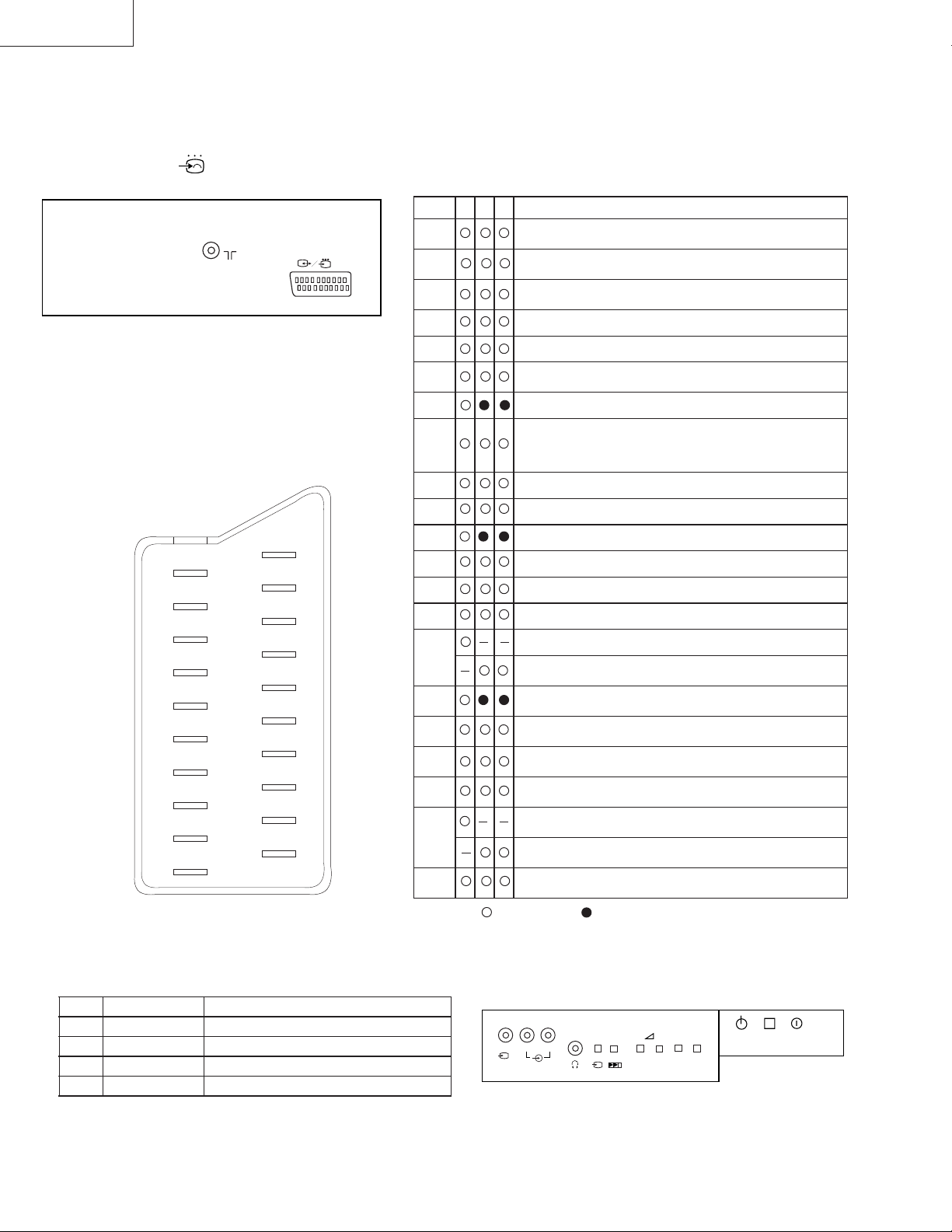
21 pin connector ( 1)
21
19
17
15
13
11
9
7
5
3
1
20
18
16
14
12
10
8
6
4
2
.oNniP 124 langiSleveLlangiS
1
2
3
4
5
6
7
8
9
01
11
21
31
41
51
61
71
81
91
02
12
Connected
BtuptuooiduA
)thgiR(
BtupnioiduA
)thgiR(
AtuptuooiduA
)tfeL(
)oiduA(dnuorG
)eulB(dnuorG
AtupnioiduA
)tfeL(
tupnieulB7.0 ± evitisop,smho57,Bd3
tcelesnoitcnuF
)lortnocVA(
)neerG(dnuorG
nepO
neerG
nepO
)deR(dnuorG
)gniknalB(dnuorG
tupnideR7.0 ± evitisop,smho57,Bd3
)langisS(
tupniamorc
tupnigniknalB
)langissY(
dnuorG
)tuptuooediV(
dnuorG
)tupnioediV(
tuptuooediV
tupnioediV
tupnioediV
)langisS(Y
dnuorgnommoC
)dliehs,gulp(
Not Connected (Open) * at 20Hz - 20kHz
7.0 ± evitisop,smho57,Bd3
V1 ± ,smho57,Bd3
V1 ± ,smho57,Bd3
V1 ± ,smho57,Bd3
smrV5.0:leveldradnatS
smrV5.0:leveldradnatS
smrV5.0:leveldradnatS
smrV5.0:leveldradnatS
edomVT:)V2-0(etatswoL
smho57:ecnadepmitupnI
*smhok1nahtsseL:ecnadepmituptuO
*smhok01nahteroM:ecnadepmituptuO
*mhok1nahtsseL:ecnadepmituptuO
*mhok01nahtsseL:ecnadepmituptuO
edomtraP:)V21-5.9(etatshgiH
smhok01eroM:ecnadepmitupnI
Fn2nahtsseL:ecnaticapactupnI
)V4.0-0(etatswoL)V3-1(etatshgiH
)Bd01+3-(V3.0:cnysevitisop
)Bd01+3-(V3.0:cnysevitisop
)Bd01+3-(V3.0:cnysevitisop
.oNniPlangiSleveLlangiS
1dnuorG
2dnuorG
3tupni)langisS(YV1 ± Bd01+3-V3.0.cnySevitisop,mho57Bd3
4tupni)langisS(CV3.0 ± .cnySevitisop,mho57Bd3
— 4 —
L/G/S/I
R/D/D/D
2
MONO
PROGR
+
-
+
-
R
Page 5

TABLE OF CONTENTS
Section Title PageSection Title Page
KV-29C3
1. GENERAL
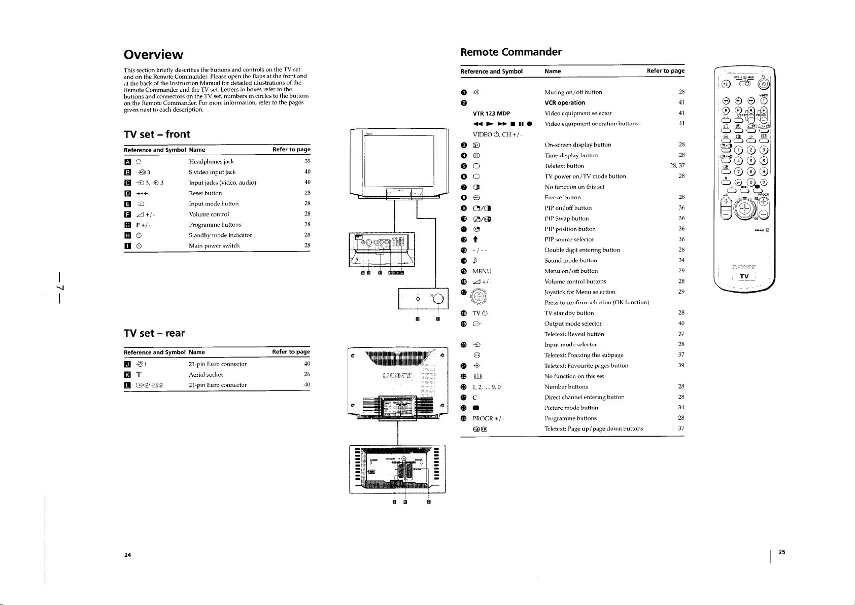
Getting Started............................................................
TV Operation..............................................................
Menu Operation..........................................................
Teletext Operation ......................................................
Optional Connections .................................................
Additional Information ...............................................
2. DISASSEMBLY
2-1. Rear Cover Removal ..................................................
2-2. Chassis Assy Removal ...............................................
2-3. Service Position ..........................................................
2-4. G Board Removal .......................................................
2-5. A Board Removal .......................................................
2-6. Picture Tube Removal ................................................
Removal and Replacement of
the Main-Bracket Bottom Paltes ................................
3. SET-UP ADJUSTMENTS
3-1. Beam Landing ............................................................
3-2. Convergence ...............................................................
3-3. Focus ..........................................................................
3-4. Screen (G2), White Balance
(Adjustment in the service mode
with remote commaner ...............................................
4. CIRCUIT ADJUSTMENTS
4-1. Electrical Adjustments................................................
4-2. Volume Electrical Adjustments..................................
4-3. Test Mode 2:...............................................................
5. DIAGRAMS
x
x
x
x
x
x
17
17
17
17
18
18
19
5-1. Block Diagram (1) ......................................................
Block Diagram (2) ......................................................
Block Diagram (3) ......................................................
Block Diagram (4) ......................................................
Block Diagram (5) ......................................................
5-2. Circuit Boards Location .............................................
5-3. Schematic Diagrams and Printed Wiring Boards .......
*A Board ....................................................................
*C Board.....................................................................
*VM Board .................................................................
*B Board.....................................................................
*G Board ....................................................................
*D Board ....................................................................
5-4. Semiconductors ..........................................................
5-5. IC Blocks ....................................................................
6. EXPLODED VIEWS
20
21
23
23
24
28
29
6-1. Chassis ........................................................................
6-2. Picture Tube ...............................................................
7. ELECTRICAL PARTS LIST ...............................
31
33
35
39
41
44
44
49
57
60
67
75
80
86
90
91
92
93
SHORT CIRCUIT THE ANODE OF THE PICTURE TUBE AND THE
ANODE CAP TO THE METAL CHASSIS, CRT SHIELD, OR CARBON
PAINTED ON THE CRT, AFTER REMOVING THE ANODE.
AN ISOLATION TRANSFORMER SHOULD BE USED DURING ANY
SERVICE TO AVOID POSSIBLE SHOCK HAZARD, BECAUSE OF
LIVE CHASSIS.
THE CHASSIS OF THIS RECEIVER IS DIRECTLY CONNECTED TO
THE AC POWER LINE.
SAFETY-RELATED COMPONENT WARNING!!
COMPONENTS IDENTIFIED BY SHADING AND MARK ON THE
SCHEMATIC DIAGRAMS, EXPLODED VIEWS AND, IN THE PARTS
LIST ARE CRITICAL FOR SAFE OPERATION. REPLACE THESE
COMPONENTS WITH SONY PARTS WHOSE PART NUMBERS
APPEAR AS SHOWN IN THIS MANUAL OR IN SUPPLEMENTS
PUBLISHED BY SONY.
CAUTION
WARNING !!
!
ATTENTION
APRES AVOIR DECONNECTE LE CAP DE L'ANODE, COURTCIRCUITER L'ANODE DU TUBE CATHODIQUE ET CELUI DE
L'ANODE DU CAP AU CHASSIS METALLIQUE DE L'APPAREIL,
OU AU COUCHE DE CARBONE PEINTE SUR LE TUBE CATHODIQUE
OU AU BLINDAGE DU TUBE CATHODIQUE.
AFIN D'EVITER TOUT RISQUE D'ELECTROCUTION PROVENANT
D'UN CHÁSSIS SOUS TENSION, UN TRANSFORMATEUR
D'ISOLEMENT DOIT ETRE UTILISÉ LORS DE TOUT DÉPANNAGE.
LE CHÁSSIS DE CE RÉCEPTEUR EST DIRECTEMENT RACCORDÉ
À L'ALIMENTATION SECTEUR.
ATTENTION AUX COMPOSANTS RELATIFS À LA
LES COMPOSANTS IDENTIFIÈS PAR UNE TRAME ET PAR UNE
MARQUE SUR LES VUES EXPLOSÉES ET LES LISTES DE
PIECES SONT D'UNE IMPORTANCE CRITIQUE PUR LA SÉCURITÉ
DU FONCTIONNEMENT. NE LES REMPLACER QUE PAR DES
COMPOSANTS SONY DONT LE NUMÉRO DE PIÉCE EST INDIQUÉ
DANS LE PRÉSENT MANUEL OU DANS DES SUPPLÉMENTS
PUBLIÉS PAR SONY.
!
ATTENTION !!
SÉCURITÉ!!
— 5 —
Page 6
Page 7
Page 8
Page 9
Page 10
Page 11
Page 12
Page 13
Page 14
Page 15
Page 16
Page 17
SECTION 2
DISASSEMBLY
— 17 —
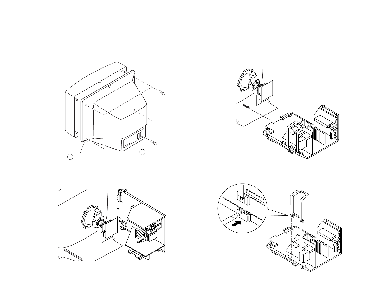
2-1. REAR COVER REMOVAL
Rear Cover
2
2-3. SERIVCE POSITION
1
Five screws
(BVTP 4x16)
2-2. CHASSIS ASSY REMOVAL
2-4. G BOARD REMOVAL
Push the claw of the bracket
in the direction of the arrow
and remove.
KV-29C3
Page 18
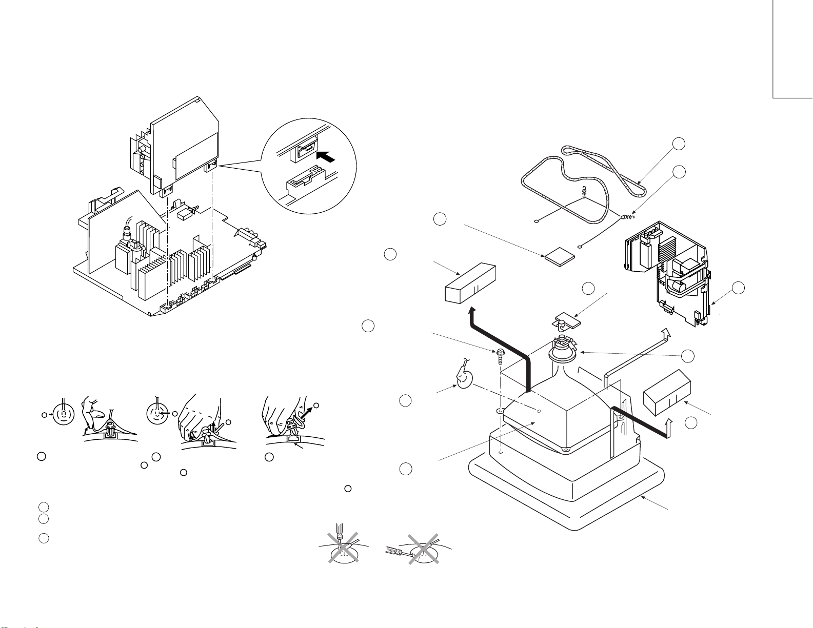
2-5. A BOARD REMOVAL 2-6. PICUTRE TUBE REMOVAL
Push the claw of the bracket
in the direction of the arrow
and remove.
C board
4
Speaker Box
2
Degaussing coil
7
Spring tension
8
KV-29C3
— 18 —
• REMOVAL OF ANODE-CAP
Note:
Short circuit the anode of the picture tube and the anode cap to the metal chassis, CRT shield or
carbon paint on the CRT, after removing the anode.
* REMOVING PROCEDURES.
a
1
Turn up one side of the rubber cap in
the direction indicated by the arrow a
2 Using a thumb pull up the rubber cap
• HOW TO HANDLE AN ANODE-CAP
1
Don't damage the surface of anode-cap with sharp shaped material !
Don't press the rubber hardly not to hurt inside of anode-caps !
2
A metal fitting called as shatter-hook terminal is built into the rubber.
3
Don’t turn the foot of rubber over hardly !
The shatter-hook terminal will stick out or damage the rubber
b
firmly in the direction indicated by the
arrow b
b
c
3 When one side of the rubber cap is
Anode button
separated from the anode button, the
anode-cap can be removed by turning
up the rubber cap and pulling it up in
the direction of the arrow c
.
Four tapping screws (M)
9
Anode cap
1
Picture tube
10
Neck assy
5
Cushion
Chassis
3
6
Deflection Yoke
Speaker Box
2
Page 19
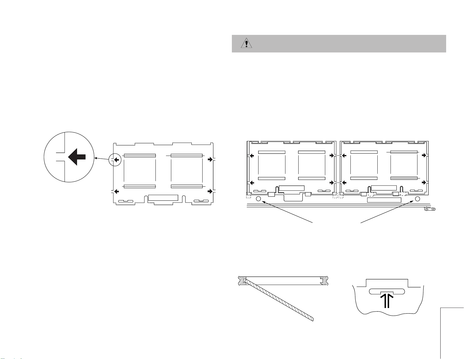
REMOVAL AND REPLACEMENT OF THE MAIN-BRACKET
BOTTOM PLATES.
For safety reasons, on no account should the plates be removed
and not refitted after servicing.
— 19 —
(1) REMOVING THE PLATES
In the event of servicing being required to the solder side of the D Board printed
circuit, the bottom plates fitted to the main chassis bracket require to be removed.
This is performed by cutting the gates with a sharp wire cutter at the locations
shown and indicated by arrows.
Note : There are 5 plates fitted to the main bracket and secured by 4 or 6 gates.
Only remove the necessary plate to gain access to the circuit board.
FOR SAFETY REASON THIS
PLATE MUST BE REMOUNTED
AFTER CUTTING AND
TAKING AWAY.
Fig 1
(2) REFITTING THE PLATES
Because the plates differ in size it is important that the correct plates are refitted in their
original location.
The plates are identified by markings A-B-C-D-E on their top side.
1. Identify the plate by locating its marking.
2. Turn the plate over noting where the marking is located.
3. Locate the corresponding marking indicated on the main chassis bracket. See Fig 2.
4. Refit the plate as indicated in Fig 3 with the markings located next to each other.
FOR SAFETY REASON THIS
PLATE MUST BE REMOUNTED
AFTER CUTTING AND
TAKING AWAY.
ATTENTION
D
E
Fig 2
FOR SAFETY REASON THIS
PLATE MUST BE REMOUNTED
AFTER CUTTING AND
TAKING AWAY.
ATTENTION
INDEX MARKING
AT BRACKET FRAME
INSERT FROM
THE BOTTOM
SIDE
Fig 3
MAIN BRACKET
In the event of the plates requiring to be
removed at a later stage, this can be achieved
by inserting a screwdriver in the snap-recess
indicated as in Fig 4 and lifting out.
KV-29C3
Fig 4
Page 20
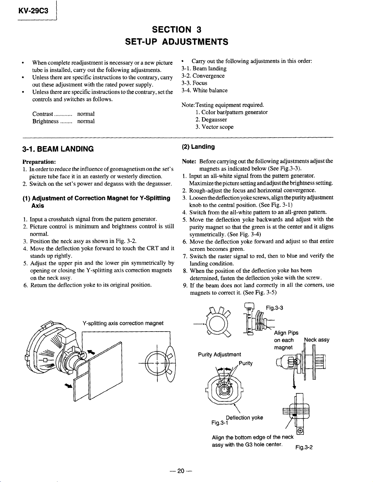
Page 21
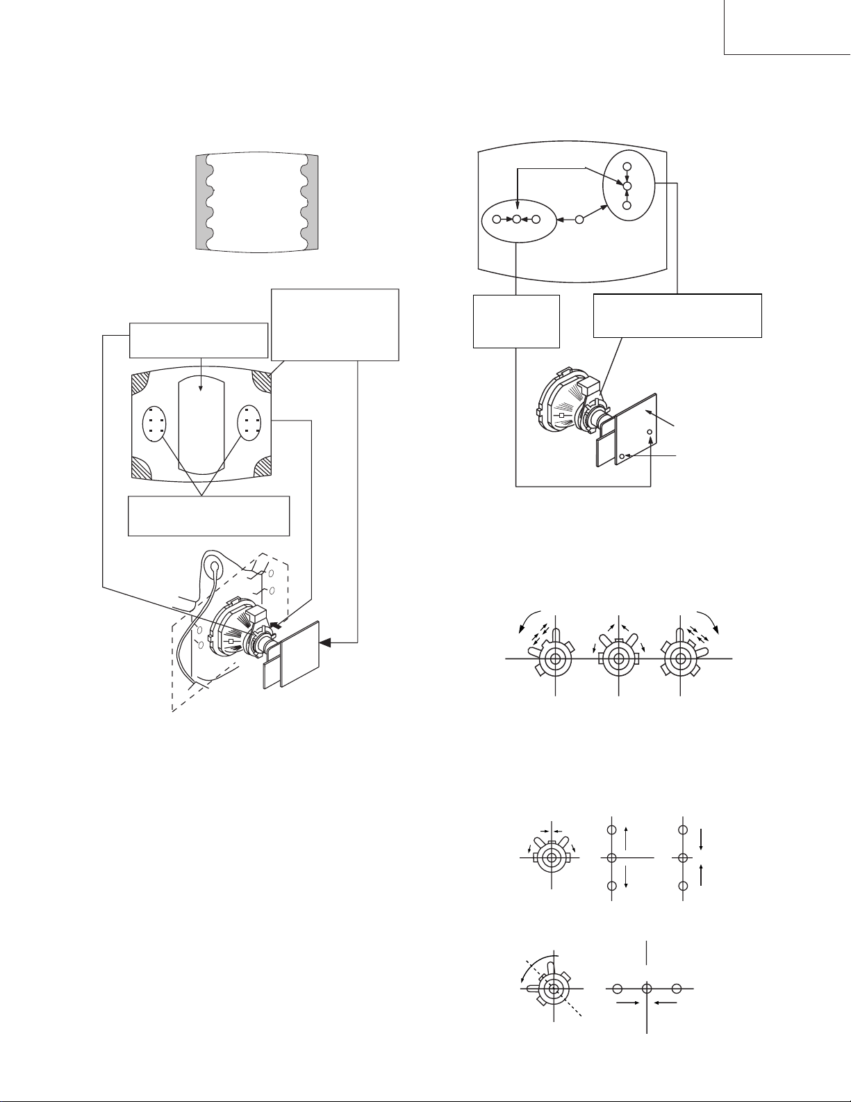
Green
GRN
Fig.3-4
RED
Red
Blue
BLU
KV-29C3
Purity control corrects
this area.
Deflection yoke positioning
corrects these areas
Fig.3-5
Disk magnets or
rotatable disk
magnets correct
these areas (a-d).
H.STAT
convergence
control
RV3701
Screen (G2)
Magnete statico verticale
V.STAT
C Board
RV3702 (H.STAT)
H.STAT convergence
• If the horizontal dots are unable to coincide with the
variable range of the H.STAT convergence, adjust together
with the V.STAT convergence while tracking.
(Adjust the convergence by tilting the V.STAT convergence
or by opening or closing the V.STAT convergence.)
(Open)
(Close)
3-2. CONVERGENCE
(1) Screen center convergence
(Static convergence)
1. Input a dot signal from the pattern generator. Normalize the
picture setting.
2. (Moving horizontally), adjust the H.STAT control so that
the horizontal red, green and blue dots coincide at the
center of screen.
3. (Moving vertically), adjust the V.STAT magnet so that the
vertical red, green and blue points coincide at the center of
screen.
— 21 —
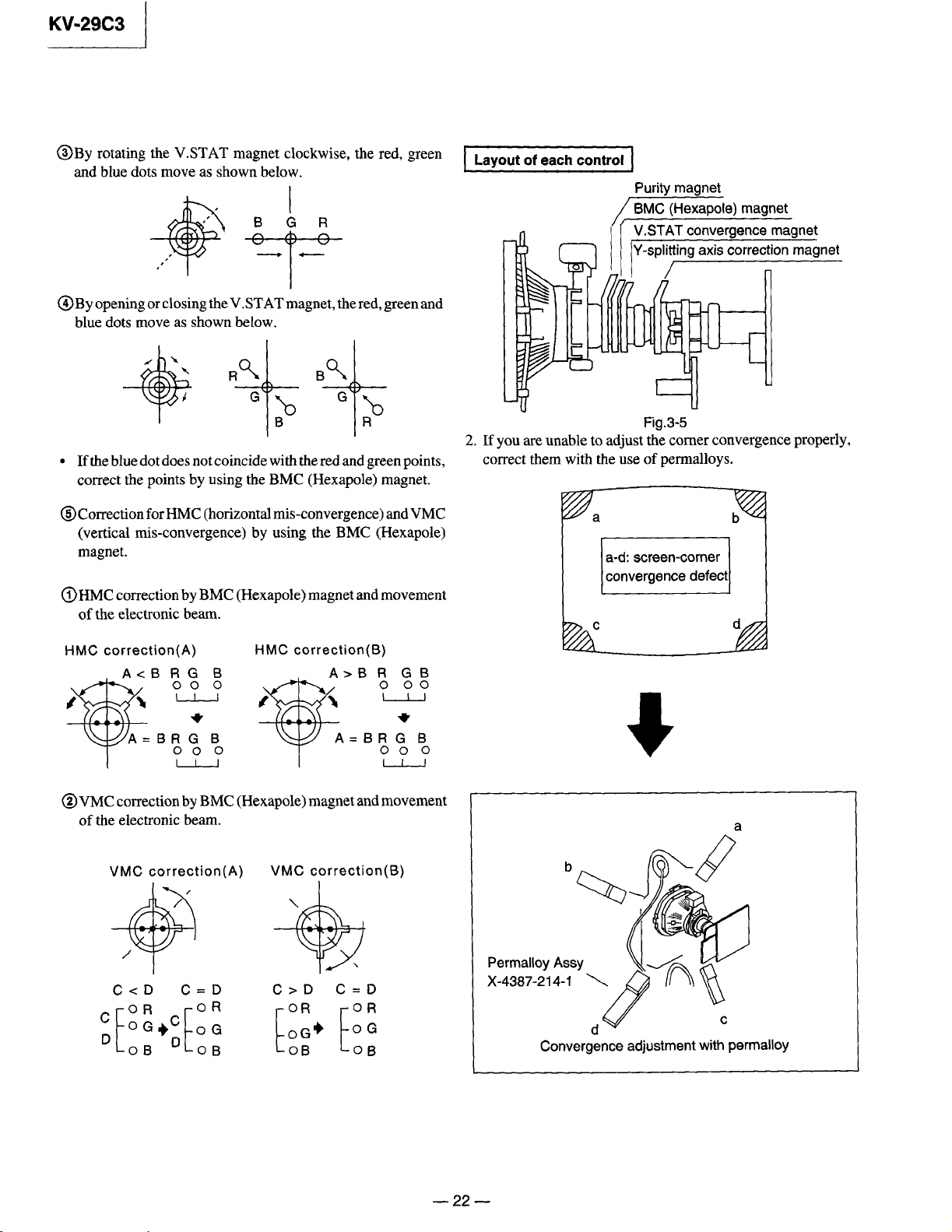
4. Movement of the red, green and blue dots by tilting the
V.STAT magnet and by opening or closing the V.STAT
magnet.
1 By opening or closing the V.STAT magnet, the red, green
and blue points move as shown below
B
G
R
B
G
R
2By rotating the V. STAT magnet counterclockwise, the
red, green and blue dots move as shown below.
B
GR
Page 22
Page 23

KV-29C3
3-3. Focus
1. Receive a television broadcast signal.
2. Normalize the picture setting.
3. Adjust the focus control on the flyback transformer for the
best focus at the center of the screen.
Bring only the center area of the screen into focus,
the magenta-ring appears on the screen. In this case, adjust
the focus to optimize the screen uniformly.
FOCUS
Video Proc. TDA4780
oNmetImetitnemtsujdAtnuomAataD
1TRBLORTNOCRESU
2LOCLORTNOCRESU
3CIPLORTNOCRESU
4EUHLORTNOCRESU
5NIAGR13
6NIAGGjdA
7NIAGBjdA
8FERLVLR13
9FERLVLGjdA
01FERLVLBjdA
11TIMILVRDKAEP36
21AMMAG13
31VEL2=FFOVEL3=NOPCSNO
41YALEDFFO
3-4. Screen (G2), White balance
(Adjustment in the service mode with
remote commander)
G2 adjustment (RV3701)
1. Input a dot signal from the pattern generator.
2. Set the Picture, Brightness and Colour to minimum.
3. Apply 170V DC from an external power supply to the
R, G and B cathodes of the CRT.
4. While watching the picture, adjust the G2 control
RV3701 [ SCREEN ] on the C board to the point just
before the return lines disappear.
White balance adjustment
1. Receive an all-white signal.
2. Enter into the Service Mode by pressing ' TEST ',
' TEST ' and ' MENU' on the Service Commander.
3. Select ' VIDEO PROC. ' from the on screen menu display
and press OK .
4. The ' VIDEO PROC TDA4780' menu will appear on the
screen.
5. Set picture to MAX.
6. Set the ' R GAIN ' to 25.
7. Adjust the ' G GAIN ' and ' B GAIN ' so that the white
balance becomes optimum.
8. Press the OK button to write the data for each item.
9. Set picture to MIN.
10. Set the ' R LVL REF ' to 31.
11. Adjust ' G LVL REF ', and ' B LVL REF '
with the left and right buttons so that the white balance
becomes optimum.
12. Press the OK button to write the data for each item.
— 23 —
Page 24

KV-29C3
SECTION 4
CIRCUIT ADJUSTMENTS
4-1. ELECTRICAL ADJUSTMENTS
Service adjustment to this model can be performed with the supplied
remote commander, RM-862.
HOW TO ENTER INTO SERVICE MODE
1. Turn on the main power switch of the set while pressing the
PROG + (plus) and PROG
- (minus) buttons on the front panel.
++
VOL PROG
--
Headphone
jack
2. “TT” will appear on the upper right corner of the screen.
3. Press " MENU " on the commander to get the service menu on
screen.
AV3
Input jacks
AV INPUT
oNmetImetitnemtsujdAtnuomAataD
1TRBLORTNOCRESU
2LOCLORTNOCRESU
3CIPLORTNOCRESU
4EUHLORTNOCRESU
5NIAGR13
6NIAGGjdA
7NIAGBjdA
8FERLVLR13
9FERLVLGjdA
01FERLVLBjdA
11TIMILVRDKAEP36
21AMMAG13
31VEL2=FFOVEL3=NOPCSNO
41YALEDFFO
51FFUBATADFFO
61XIRTAMCSTNFFO
71VTDHFFO
SECIVEDSECIVED
SECIVEDSECIVED
SECIVED
VTtinI
tsujdAbuS
corPoediV
niaMceDloC
tnoC.tcelfeD
buSceDloC
xoBerutaeF
lA
AD
PIPelgniS
dnuoS
ted32eniL
edisotuA&rednopsimuL,piP
0874ADT
3
4419ADT
1639ADS
3419ADT
456C78S
0719ADT
0829ADS
8829ADS
4. Push the joystick up (green) or down (blue) on the remote
commander to select the adjustment item.
5. Press the center button to proceed to the next menu.
6. If the adjustment item is 'Video Proc.', push the down button to
move to 'Video Proc.'.
7. The Menu as indicated in Fig 4-3 will appear on the screen.
8. Move the joystick up or down to move to the adjustment item and
press the center (OK) button.
9. Change the data in order to comply with each standard.
81LBSFFFO
91FFOTUCOTUANO
02SID2WSFFFO
122WSFFFO
22SID1WSFFFO
321WSFFFO
42KCALBTPADAFFO
52V1HGIHYFFO
622DOMFFO
72HCTERTSEULBFFO
82TUOMVFFO
92SBAVRDKAEPNO
03TIMILKAEPTSNCEMITFFO
Fig. 4-3
— 24 —
Page 25

SDA9361 (VIDEO PROC.)
KV-29C3
oNmetImetitnemtsujdAtnuomAataD
1EDHNO
2RV0
3LBARNO
4SIDKLBFFO
5QRFENIL*2HF2NO
6EDOMYBDNATSFFO
7LACITREVNO
8TCELESKLBESBFFO
9NACSTRATSESSFFO
01NACSDERTRATSESRSFFO
11DNABDRAUGEBGFFO
21ELBATEMITNACSETSFFO
31NOITPADAFLESASNNO
41TFIHSVJDA
51EZISVJDA
61NILVJDA
71ROC-SVJDA
87="52
81PMOCTHEV
91EZISHJDA
02ESAHPNIPJDA
12PMANIPJDA
22NIPROCPUJDA
32NIPROCWOLJDA
42PMOCTHEH
52TFIHSHJDA
62ELGNAVJDA
001="92
63="82
="23
87="52
001="92
63="82
="23
oNmetImetitnemtsujdAtnuomAataD
92A/D0
03EMITKLBV0
13EMITKLBH0
23NACSVRATS0
33ESAHPKLBH0
430HTDIWNACSV0
531HTDIWNACSV0
63DNABDRAUG0
73NACSDERTRATS0
83SDLEIFREBMUN1
93ECALRETNINONINFFO
04DERESIONCNYSVRNNO
14LBVHTIWCCSNO
24DLEIF/SENILNIM0
34DLEIF/SENILXAM0
44PMOCTHECFA0
54QERFLLP6
64RCVNO
74DOMNEGFFO
84DIWSHNO
94ESAHPHTNI932
05HTDIWMWP0
15RCVYSIONFFO
25PIZLLIKFFO
35DR3CTFFO
45FFO4PAGDNABFFO
55FFOPAGDNABFFO
65PAGDNAB0
72WOBVJDA
82TRATSMWP0
— 25 —
Page 26

KV-29C3
TDA4780 (VIDEO PROC.)
oNmetImetitnemtsujdAtnuomAataD
1TRBLORTNOCRESU
2LOCLORTNOCRESU
3CIPLORTNOCRESU
4EUHLORTNOCRESU
5NIAGR52
6NIAGGjdA
7NIAGBjdA
8FERLVLR13
9FERLVLGjdA
01FERLVLBjdA
11TIMILVRDKAEP0
21AMMAG13
31VEL2=FFOVEL3=NOPCSNO
41YALEDFFO
51FFUBATADFFO
61XIRTAMCSTNFFO
71VTDHFFO
81LBSFFFO
91FFOTUCOTUANO
02SID2WSFFFO
122WSFFFO
221WSFFFO
321WSFFFO
42KCALBTPADAFFO
52V1HGIHYFFO
622DOMFFO
72HCTERTSEULBFFO
82TUOMVFFO
92SBAVRDKAEPNO
03TIMILKAEPTSNCEMITFFO
— 26 —
Page 27

KV-29C3
DEFLECTION SYSTEM ADJUSTMENT
V SIZE
1. Enter into the service mode and select 'Deflect cont.'.The
'Deflect cont. SDA9361' adjustment menu will be displayed.
2. Select and adjust each item in order to get an optimum image.
oNmetImetitnemtsujdAtnuomAataD
V POS
V LIN
1EDHNO
2RV0
3LBARNO
4SIDKLBFFO
5QRFENIL*2HF2NO
6EDOMYBDNATSFFO
7LACITREVNO
8TCELESKLBESBFFO
9NACSTRATSESSFFO
01NACSDERTRATSESRSFFO
11DNABDRAUGEBGFFO
H SIZE
H PIN CUSH
H TILT
21ELBATEMITNACSETSFFO
31NOITPADAFLESASNNO
41TFIHSVJDA
51EZISVJDA
61NILVJDA
71ROC-SVJDA
81PMOCTHEV
91EZISHJDA
02ESAHPNIPJDA
12PMANIPJDA
22NIPROCPUJDA
32NIPROCWOLJDA
42PMOCTHEH
52TFIHSHJDA
62ELGNAVJDA
72WOBVJDA
H UP COR
H LOWER COR
87="52
001="92
63="82
AFC V BOW
AFC V ANGLE
H POS
87="52
001="92
63="82
82TRATSMWP0
— 27 —
Page 28

KV-29C3
4-2. VOLUME ELECTRICAL ADJUSTMENTS
Sub Brightness Adjustment
1. Enter Service Mode (Device Menu).
2. Select 'SUB ADJUST MENU'.
tnemtsujdabuStnemtsujdabuS
tnemtsujdabuStnemtsujdabuS
tnemtsujdabuS
erutciPbuS
roloCbuS
ssenthgirBbuS
retneC3/4
retneC-HPAP
tesffO-EWHPAP
3. Adjust the value according to the following advice.
Sub Color Adjustment
1. Input a PAL color bar signal.
2. Connect an oscilloscope to CN3703.
3. Enter into 'SERVICE MODE'.
4. Choose 'SUB ADJUST'.
5. Enter into Sub Color mode.
6. Adjust data so that the right sides of the waveforms are of equal
height.
SAME LEVEL
— 28 —
Page 29

KV-29C3
4-3. TEST MODE 2:
Is available by pressing the Test button twice, OSD “TT” appears. The functions described below are available by pressing the two numbers. To
release Test Mode 2, press 0, 10, 20 ... twice or switch the TV into Standby Mode. Pressing the two Local Control buttons ( + and – ) during Power
ON will also switch into "TT" mode.
In TT mode, it is possible to remove the Menu from the screen by pressing the Speaker Off button once. Pressing the Speaker OFF button a second
time will cause the menu to reappear . The Function is kept even when the menu is not displayed!!
00ffoedomTT-edomlamronotkcabhctiwS
10nounemecivreshctiwS
20noitcuderesioNotsseccatceriD
30%03otemulovteS
40"edoMecivreS"niunemecivreS
50"edoMnoitcudorP"niunemecivreS
60%08otemuloVteS
70edoMgnigA
80noitidnoCgnippihS
90teseRegaugnaL
01deteledeblliwrebmunTTehT
11ecnalaBotsseccatceriD
21euHotsseccatceriD
31noitarugifnoctesVTfoyalpsiD
41yalpsiDofnInoitcudorP
51MORmorfgolanAdaeR
61MVNniFgolanAevaS
71
81noitcnufoN
91noitcnufoN
0201TTeeS
120>-)4+(>-)4-(:noitcnufcitamotuanoitatoRerutciP
22yalpsiDrotinoMrorrE
32.tnemtsujdAssenthgirBbuSotsseccatceriD
42.ruoloCbuSotsseccatceriD
52yalpsiDuneMsutatS
62)eporuEtseW>-60tesrahC(noitcelesretcarahCtxeT
72)eporuEtsaE>-83tesrahC(noitcelesretcarahCtxeT
82
92
0301TTeeS
13noitcnufon
23noitcnufon
33noitcnufon
43noitcnufon
53noitcnufon
63noitcnufon
73noitcnufon
83noitisoPneercS
93elbaTemmargorPteseR
0401TTeeS
14niMerutciP
24noitcnufon
34noitcnufon
44noitcnufon
54edomtcetorPotMVNteS
.rettimsnartlaicepSaybenodebnac
:secruosVAehtrofslebaLehtsteserpnoitcnufsihT
.4CY,4VA,3CY,3VA,2CY,2VA,BGR,1VA
)eporuEtseW>-04tesrahC(noitcelesretcarahCtxeT
hsilgnESU
)eporuEtseW>-55tesrahC(noitcelesretcarahCtxeT
hsikruT
64
74noitcnufon
84noitcnufon
94ezilaitinIweN
0501TTeeS
15.detavitcasiedomobortS
25noitcnufon
35noitcnufon
45
55hgiHrecilS
65oNrecilS
75nouneMecivreStxetageM
85wodniWedoCgnimarFllamSXTM
.derotseb
)esu
gnittesserplennahcehT.edoMgnittesserPlennahCRI
sraeppayalpsidtcelesrebmuNRP-->-64TT:ecneuqeS
llahslennahcehterehwmorf.oN.gorPtceleS
--<ecneuqesRIrofgnitiawsiVTwoN>--
si64TTstratsnoissimsnartRIonfI>--
,evitcasi64TTnehw:etoN!--<sces02retfadesaeler
!atadGORPsadeterpretnieblliwnoissimsnartyna
noitcudorP(MVnoitaludoMyticoleVotsseccatceriD
— 29 —
Page 30

KV-29C3
95wodniWedoCgnimarFediWXTM
0601TTeeS
16noitcnufon
26noitcnufon
36noitcnufon
46)esunoitcudorP(sdnammocevalSCIIllateseR
56MVNnisedocrorrederotsteseR
66sulPlaPdnaxoberutaeF
76noitcnufon
86no-srorrEerongI
96ffo-srorreerongI
0701TTeeS
17noitcnufon
27noitcnufon
37.desaercedpetsenoleveltxetBGRtxetageM
47
57noitcnufon
670639ADC
SDA9361
770829ADS
87PIP
97noitcnufon
0801TTeeS
18gnittesatadtluafeD456C78S
no function
28gnittesatadtluafeD0719ADT
38gnittesatadtluafeDPW5817AAS
no function
48gnittesatadtluafeD0874ADT
TDA9143 Default data setting
58gnittesatadtluafeD4419ADT
68gnittesatadtluafeD3419ADT
78gnittesatadtluafeD8829ADS
88naissuRtesrahC
1xam(desaercedpetsenoleveltxetBGRtxetageM
)esunoitcudorP()h0Emorfgnitratsnwodspets
98)cse(naissuRtesrahC
0901TTeeS
— 30 —
Page 31

KV-29C3
5-2. CIRCUIT BOARDS LOCATION
VM
C
D
B
A
G
5-3. SCHEMATIC DIAGRAMS AND PRINTED WIRING BOARDS
Note :
• All capacitors are in µF unless otherwise noted. pF: µµF
50WV or less are not indicated except for electrolytic and
tantalums.
Reference information
RESISTOR : RN METAL FILM
• All resistors are in ohms.
k = 1000 , M = 1000K
• Indication of resistance, which does not have one for rating
electrical power, is as follows.
Pitch : 5 mm
Rating electrical power W
1
/
4
COIL : LF-8L MICRO INDUCTOR
CAPACITOR : TA TANTALUM
• : nonflammable resistor.
• : internal component.
• : panel designation, or adjustment for repair.
• All variable and adjustable resistors have characteristic curve
B, unless otherwise noted.
• : earth - ground.
• : earth - chassis.
• : no mounted.
• Readings are taken with a colour-bar signal input.
Note : The components identified by shading and marked
are critical for safety. Replace only with the
part number specified.
Note : Les composants identifies par une trame et une
marque sont critiques pour la securite.
Ne les remplacer que par une piece portant le
numero specifie.
• Readings are taken with 10MΩ digital multimeter.
• Voltages are dc with respect to ground unless otherwise noted.
• Voltage variations may be noted due to normal production
• All voltages are in V.
• Circled numbers are waveform references.
• : B+ bus.
• : signal path. (RF)
: RC SOLID
: FPRD NONFLAMMABLE CARBON
: FUSE NONFLAMMABLE FUSIBLE
: RS NONFLAMMABLE METAL OXIDE
: RB NONFLAMMABLE CEMENT
: RW NONFLAMMABLE WIREWOUND
: ADJUSTABLE RESISTOR
: PS STYROL
: PP POLYPROPYLENE
: PT MYLAR
: MPS METALIZED POLYESTER
: MPP METALIZED POLYPROPYLENE
: ALB BIPOLAR
: ALT HIGH TEMPERATURE
: ALR HIGH RIPPLE
tolerances.
— 44 —
Page 32

KV-29C3
5-4. SEMICONDUCTORS
BA7046F
BA7046F-T1
MB3793-42PNF
MB3793-42PNF-ER
85
1
4
( TOP VIEW )
CXA1855Q-T6
25
36
37
48
12
1
( TOP VIEW )
LM2940CT-9.0
LM2940T-8.0
LM2940T-9.0
L4941BV
TEA7605
MC74F240DWR2
20 11
110
( TOP VIEW )
MSP3400C-PS-C6-T-ND
MSP3410B-PS-F7-T-ND
SDA30C164-GEG
SDA5273-C126-GEG
9
24
13
10
18
26
( TOP VIEW )
61
60
52
44
433527
68
1
M27C4001-15C1
M27C4001-15C1-AE401
P83C654EBA/560
SDA9280A41
51
52
68
1
( TOP VIEW )
SAA4945H/V1
SDA9361
34
44
1
SAA4952WP/V1
640144
7
TC4S66F
TC4S66F-TE85L
35
34
18
17
1
2
3
5
4
TDA4665T-T
16
2333
22
12
11
39
1
( TOP VIEW )
TDA4780/V3
28 15
1
( TOP VIEW )
9
8
14
IN
OUT
GND
LM393P
M5216P
ST24C16FB6
TDA2822M
UPC393C
7
6
8
2
3
1
LM78L05ACZ
LM78L12ACZ
L78L05ACZ-AP
L78L12ACZ-AP
132 30
4
5
( TOP VIEW )
29
21
2014
17
18 28
( TOP VIEW )
SBX1981-51
29
TDA6111Q
TDA6111Q/N4
19
PC123F2
PC123FY2
4
3
5
1
2
4
PQ05RF21
SDA9288X-A141
TDA8755T-T
32 17
1
( TOP VIEW )
TDA7265
16
1
11
STV9379
TDA7309
1
2
3
4
1 : V IN
2 : V OUT
IN
OUT
GND
3 : GND
4 : ON/OFF CONTROL
1
7
20
1
( TOP VIEW )
11
10
— 86 —
Page 33

KV-29C3
TDA9143/N2
32
1
( TOP VIEW )
TMS4C2972-26DTR
TMS4C2972-28DTR
36 19
1
( TOP VIEW )
18
74HCT4046AD/S470
16 9
1
( TOP VIEW )
74LVC08D
14 8
1
( TOP VIEW )
7
BC546B
BC556B
17
16
DTA144EK
DTA144EK-T146
DTC114EK
DTC114EKA-T146
8
DTC123EK
DTC123EK-T146
DTC124EKA-T146
DTA144ESA
DTA144ESA-TP
DTC114ESA-TP
DTC144ESA-TP
2SA1175-HFE
2SA733-K
BF421L-AMMO
2SC2500-B
2SC2551-O
2SC2551O-TPE2
E
B
C
BF871-127
E
C
B
DTC144EK
DTC144EK-T146
DTC144EKA-T146
2SA1037K-T-146-R
2SA1162-G
2SC2412K-QR
2SC2412K-T-146-R
C
B
2SA933AS-RT
2SA933AS-QRT
2SA933S-RT
2SC1740S-RT
2SC2785-HFE
IRF620
B
2SA1837
B
E
C
C
E
2SC4834NP-F09
B
C
E
DAN202K
DAN202K-T-146
3
1
2
2
3
1
DAP202K
DAP202K-T-146
2SC2611
2SC2688-LK
2SC3271-N
E
E
B
C
2SC3997CA
MARKING SIDE VIEW
3
2
2
3
DA204K
DA204K-T-146
3
2
1
1
1
S
G
D
BF199
BF199-AMMO
E
C
B
E
IMZ1A-T109
3
2
1
5
4
3
2
3
2
1
D1NL20
D1NL20-TA
B
C
B
C
E
D1NL20-TR
EGP20G
EL1Z
GP08D
GP08DPKG23
2SC4793
4
5
6
6
B
1
C
E
MTZJ-T-77-9.1
MTZJ-T-77-9.1A
R2K-V1
RGP02-20EG23
RGP02-20EL-6394
RGP10GPKG23
RGP15GPKG23
S2LA20F
1SS133T-77
1SS83
1SS83TD
CATHODE
ANODE
— 87 —
Page 34

KV-29C3
D10SC4M
1
1
D4SB60L
D4SB60L-F
RBA-402L
ERC38-06
3
2
2
CATHODE
MA3030-H(TX)
MA3033-L
MA3033L-TX
3
MA3056M-TX
MA3062M-TX
RD5.6M-B2
3
23
SLA-570KT3F
1
2
NC
1
ANODE
CATHODE
MA3051L-TX
CATHODE
ANODE
MTZJ-T-77-13B
MTZJ-T-77-15B
MTZJ-T-77-2.2A
MTZJ-T-77-33C
MTZJ-T-77-39C
MTZJ-T-77-5.6B
MTZJ-T-77-9.1B
MTZJ-33C
MTZJ-39C
RD15ES-B2
RD5.6ESB2
RD9.1ESB2
1SS119-25
1SS119-25TD
MTZJ-13B
ANODE
ERD08M-15
CATHODE
ANODE
ESAD39M-06C
ESAD39M-06CF38
RD12SB2
UDZ-TE-17-12B
ANODE
S1VB20-S
S1VB40
+
CATHODE
ANODE
~
~
CATHODE
-
1
2
3
~
~
1
3
2
+
-
— 88 —
Page 35

Page 36

KV-29C3
7
SECTION 6
EXPLODED VIEWS
NOTE :
• Items with no part number and no description are not stocked because they
are seldom required for routine service.
• The construction parts of an assembled part are indicated with a collation
number in the remarks column.
• Items marked " * " are not stocked since they are seldom required for
routine service. Some delay should be anticipated when ordering these
items.
6-1. CHASSIS
12
9
11
The components identified by
shading and marked are critical
for safety.
Replace only with the part number
specified.
10
8
Les composants identifies par une
trame et une marque sont
critiques pour la securite.
Ne les remplacer que par une piece
portant le numero specifie.
14
6
5
4
1
3
2
REF NO PART NO DESCRIPTION REMARK
1 1-571-433-21 SWITCH, PUSH (AC POWER)
2 *4-203-415-01 BRACKET, MAIN
3 1-751-680-11 CORD, POWER (WITH NOISE FILTER)
2.5A/250V
4 *4-202-531-01 AC CORD LOCK (SC)
5 *A-1640-246-A D BOARD, COMPLETE
6 1-453-222-11 TRANSFORMER ASSY, FLYBACK
(NX-4003/U2B4)
7 *A-1636-021-A G BOARD, COMPLETE
8 *4-203-613-01 SUPPORTER, G
9 1-693-338-11 TUNER (TUVIF) (AEP)
(KV-29C3A/29C3D/29C3E/29C3K/29C3R)
1-693-340-11 TUNER (TUVIF) (FR) (KV-29C3B)
10 *A-1632-572-A A BOARD, COMPLETE (KV-29C3A)
*A-1632-570-A A BOARD, COMPLETE (KV-29C3B)
*A-1632-498-A A BOARD, COMPLETE (KV-29C3D)
*A-1632-571-A A BOARD, COMPLETE (KV-29C3E)
*A-1632-574-A A BOARD, COMPLETE (KV-29C3K)
*A-1632-573-A A BOARD, COMPLETE (KV-29C3R)
REF NO PART NO DESCRIPTION REMARK
11 *4-203-612-01 BRACKET, A-B
12 *A-1620-080-A B BOARD, COMPLETE
13 4-202-993-11 COVER, REAR
14 4-039-358-01 SCREW (4X16), (+) BV TAPPING
13
— 90 —
Page 37

6-2. PICTURE TUBE
61
74
75
76
77
70
KV-29C3
69
68
78
53
51
52
54
55
72
70
73
57
56
58
71
63
62
60
59
The components identified by
shading and marked are critical
for safety.
Replace only with the part number
specified.
64
66
67
65
70
73
72
71
70
Les composants identifies par une
trame et une marque sont
critiques pour la securite.
Ne les remplacer que par une piece
portant le numero specifie.
REF NO PART NO DESCRIPTION REMARKREF NO PART NO DESCRIPTION REMARK
51 X-4200-293-1 BEZNET ASSY (M) 52-57
(KV-29C3A/29C3D/29C3K/29C3R)
X-4200-295-1 BEZNET ASSY (M-N) 52-57
(KV-29C3B/29C3E)
52 4-392-036-01 CATCHER PUSH
53 4-203-013-31 DOOR (PAINTED)
54 4-202-992-01 BUTTON, POWER
55 4-202-964-01 SPRING
56 X-4200-294-1 PANEL ASSY (M)
(KV-29C3A/29C3D/29C3K/29C3R)
X-4200-296-1 PANEL ASSY (M-N) (KV-29C3B/29C3E)
57 4-203-524-01 WINDOW ORNAMENTAL
58 4-203-098-01 SUPPORTER, CRT
59 8-733-856-05 PICTURE TUBE (SD-269) (M68LCT60X)
60 8-451-466-11 DEFLECTION YOKE (Y29GXC2B)
61 3-704-495-01 SPACER, DY
62 1-251-317-31 CAP ASSY, HIGH-VOLTAGE
— 91 —
63 4-203-043-01 SCREW (M), PT
64 8-453-005-21 NECK ASSY PICTURE TUBE (NA297-M2)
65 *A-1644-077-A VM BOARD, COMPLETE
66 *A-1638-097-A C BOARD, COMPLETE
67 4-369-318-51 SPRING, TENSION
68 1-406-807-11 COIL DEGAUSSING
69 4-202-749-01 HOLDER, D.G.C. (29"/32")
70 *4-202-988-01 CUSHION, BOX
71 *A-1678-087-A BOX ASSY 72-73
72 1-504-146-11 SPEAKER (5X11CM)
73 4-200-999-01 STOPPER
74 4-308-870-00 CLIP, LEAD WIRE
75 1-452-032-00 MAGNET, DISK; 10MM Ø
76 1-452-094-00 MAGNET, ROTATABLE DISK; 15MM Ø
77 X-4387-214-1 PERMALLOY ASSY, CORRECTION
78 3-701-007-00 BAND, BINDING
Page 38

KV-29C3
The components identified by
shading and marked are critical
SECTION 7
for safety.
Replace only with the part number
ELECTRICAL PARTS LIST
specified.
Les composants identifies par
une trame et une marque sont
critiques pour la securite.
Ne les remplacer que par une piece
portant le numero specifie.
REF.NO. PART NO. DESCRIPTION REMARK
When indicating parts by reference
number, please include the board
name.
CAPACITORS COILS
MF : mF , PF : mmF MMH : mH , µH : mH
• Items marked " * " are not stocked since
they are seldom required for routine
service. Some delay should be anticipated
when ordering these items.
• All variable and adjustable resistors
have characteristic curve B, unless
otherwise noted.
RESISTORS
REF.NO. PART NO. DESCRIPTION REMARK
• All resistors are in ohms
B
REF.NO. PART NO. DESCRIPTION REMARK
*A-1620-080-A B BOARD, COMPLETE
*****************
< CAPACITOR >
C407 1-126-969-11 ELECT 220MF 20% 50V
C408 1-164-004-11 CERAMIC CHIP 0.1MF 10% 25V
C409 1-162-638-11 CERAMIC CHIP 1MF 16V
C410 1-162-638-11 CERAMIC CHIP 1MF 16V
C411 1-162-638-11 CERAMIC CHIP 1MF 16V
C412 1-163-037-11 CERAMIC CHIP 0.022MF 10% 50V
C413 1-163-037-11 CERAMIC CHIP 0.022MF 10% 50V
C414 1-164-005-11 CERAMIC CHIP 0.47MF 25V
C415 1-162-638-11 CERAMIC CHIP 1MF 16V
C416 1-162-638-11 CERAMIC CHIP 1MF 16V
• F : nonflammable
REF.NO. PART NO. DESCRIPTION REMARK
C1806 1-110-501-11 CERAMIC CHIP 0.33MF 10% 16V
C1807 1-126-963-11 ELECT 4.7MF 20% 50V
C1808 1-163-125-00 CERAMIC CHIP 220PF 5% 50V
C1809 1-163-125-00 CERAMIC CHIP 220PF 5% 50V
C1810 1-162-638-11 CERAMIC CHIP 1MF 16V
C1811 1-163-989-11 CERAMIC CHIP 0.033MF 10% 25V
C1812 1-163-989-11 CERAMIC CHIP 0.033MF 10% 25V
C1813 1-164-489-11 CERAMIC CHIP 0.22MF 10% 16V
C1814 1-163-125-00 CERAMIC CHIP 220PF 5% 50V
C1815 1-163-125-00 CERAMIC CHIP 220PF 5% 50V
C1816 1-126-963-11 ELECT 4.7MF 20% 50V
C1817 1-164-004-11 CERAMIC CHIP 0.1MF 10% 25V
C1818 1-164-004-11 CERAMIC CHIP 0.1MF 10% 25V
C1819 1-163-097-00 CERAMIC CHIP 15PF 5% 50V
The components identified by
shading and marked are critical
for safety.
Replace only with the part number
specified.
Les composants identifies par
une trame et une marque sont
critiques pour la securite.
Ne les remplacer que par une piece
portant le numero specifie.
C417 1-162-638-11 CERAMIC CHIP 1MF 16V
C418 1-164-004-11 CERAMIC CHIP 0.1MF 10% 25V
C419 1-164-004-11 CERAMIC CHIP 0.1MF 10% 25V
C420 1-164-004-11 CERAMIC CHIP 0.1MF 10% 25V
C421 1-162-568-11 CERAMIC CHIP 0.33MF 10% 16V
C422 1-162-638-11 CERAMIC CHIP 1MF 16V
C427 1-126-963-11 ELECT 4.7MF 20% 50V
C428 1-164-004-11 CERAMIC CHIP 0.1MF 10% 25V
C429 1-163-103-00 CERAMIC CHIP 27PF 5% 50V
C430 1-163-103-00 CERAMIC CHIP 27PF 5% 50V
C431 1-164-004-11 CERAMIC CHIP 0.1MF 10% 25V
C432 1-164-004-11 CERAMIC CHIP 0.1MF 10% 25V
C433 1-164-004-11 CERAMIC CHIP 0.1MF 10% 25V
C434 1-163-117-00 CERAMIC CHIP 100PF 5% 50V
C435 1-163-145-00 CERAMIC CHIP 0.0015MF 5% 50V
C438 1-164-004-11 CERAMIC CHIP 0.1MF 10% 25V
C439 1-126-964-11 ELECT 10MF 20% 50V
C440 1-126-964-11 ELECT 10MF 20% 50V
C441 1-163-037-11 CERAMIC CHIP 0.022MF 10% 50V
C446 1-163-125-00 CERAMIC CHIP 220PF 5% 50V
C450 1-164-004-11 CERAMIC CHIP 0.1MF 10% 25V
C451 1-164-004-11 CERAMIC CHIP 0.1MF 10% 25V
C452 1-163-103-00 CERAMIC CHIP 27PF 5% 50V
C453 1-164-004-11 CERAMIC CHIP 0.1MF 10% 25V
C454 1-162-568-11 CERAMIC CHIP 0.33MF 10% 16V
C455 1-126-964-11 ELECT 10MF 20% 50V
C1801 1-126-963-11 ELECT 4.7MF 20% 50V
C1802 1-163-141-00 CERAMIC CHIP 0.001MF 5% 50V
C1803 1-126-964-11 ELECT 10MF 20% 50V
C1804 1-164-004-11 CERAMIC CHIP 0.1MF 10% 25V
C1820 1-163-097-00 CERAMIC CHIP 15PF 5% 50V
C1821 1-164-004-11 CERAMIC CHIP 0.1MF 10% 25V
C1822 1-164-004-11 CERAMIC CHIP 0.1MF 10% 25V
C1823 1-164-004-11 CERAMIC CHIP 0.1MF 10% 25V
C1824 1-164-004-11 CERAMIC CHIP 0.1MF 10% 25V
C1825 1-126-964-11 ELECT 10MF 20% 50V
C1826 1-164-004-11 CERAMIC CHIP 0.1MF 10% 25V
C1827 1-164-004-11 CERAMIC CHIP 0.1MF 10% 25V
C1828 1-163-117-00 CERAMIC CHIP 100PF 5% 50V
C1829 1-163-097-00 CERAMIC CHIP 15PF 5% 50V
C1830 1-164-004-11 CERAMIC CHIP 0.1MF 10% 25V
C1831 1-163-125-00 CERAMIC CHIP 220PF 5% 50V
C1850 1-163-111-00 CERAMIC CHIP 56PF 5% 50V
C1851 1-163-989-11 CERAMIC CHIP 0.033MF 10% 25V
C1852 1-164-005-11 CERAMIC CHIP 0.47MF 16V
C1856 1-163-105-00 CERAMIC CHIP 33PF 5% 50V
C1857 1-163-101-00 CERAMIC CHIP 22PF 5% 50V
C1858 1-163-989-11 CERAMIC CHIP 0.033MF 10% 25V
C1859 1-164-005-11 CERAMIC CHIP 0.47MF 16V
C1860 1-126-961-11 ELECT 2.2MF 20% 50V
C1861 1-163-097-00 CERAMIC CHIP 15PF 5% 50V
C1862 1-163-097-00 CERAMIC CHIP 15PF 5% 50V
C1864 1-163-002-11 CERAMIC CHIP 270PF 10% 50V
C1866 1-126-964-11 ELECT 10MF 20% 50V
C1867 1-164-004-11 CERAMIC CHIP 0.1MF 10% 25V
C1868 1-164-004-11 CERAMIC CHIP 0.1MF 10% 25V
C1869 1-164-004-11 CERAMIC CHIP 0.1MF 10% 25V
C1870 1-164-004-11 CERAMIC CHIP 0.1MF 10% 25V
C1871 1-164-004-11 CERAMIC CHIP 0.1MF 10% 25V
C1872 1-164-004-11 CERAMIC CHIP 0.1MF 10% 25V
C1805 1-164-489-11 CERAMIC CHIP 0.22MF 10% 16V
C1873 1-164-004-11 CERAMIC CHIP 0.1MF 10% 25V
— 92 —
Page 39

The components identified by
shading and marked are critical
for safety.
Replace only with the part number
specified.
REF.NO. PART NO. DESCRIPTION REMARK REF.NO. PART NO. DESCRIPTION REMARK
Les composants identifies par
une trame et une marque sont
critiques pour la securite.
Ne les remplacer que par une piece
portant le numero specifie.
KV-29C3
B
C1874 1-164-004-11 CERAMIC CHIP 0.1MF 10% 25V
< ENCAPSULATED FILTER >
C1875 1-164-004-11 CERAMIC CHIP 0.1MF 10% 25V
C1879 1-164-004-11 CERAMIC CHIP 0.1MF 10% 25V
C1880 1-164-004-11 CERAMIC CHIP 0.1MF 10% 25V
FL1801 1-239-882-11 FILTER, LOW PASS
FL1803 1-415-940-11 DELAY LINE
FL1807 1-236-071-11 ENCAPSULATED COMPONENT
C1881 1-164-004-11 CERAMIC CHIP 0.1MF 10% 25V
C1882 1-164-004-11 CERAMIC CHIP 0.1MF 10% 25V
FL1808 1-236-071-11 ENCAPSULATED COMPONENT
FL1809 1-236-071-11 ENCAPSULATED COMPONENT
C1883 1-164-004-11 CERAMIC CHIP 0.1MF 10% 25V
C1886 1-164-004-11 CERAMIC CHIP 0.1MF 10% 25V
< IC >
C1887 1-164-004-11 CERAMIC CHIP 0.1MF 10% 25V
IC402 8-759-275-36 IC TDA4780/V3
C1889 1-164-004-11 CERAMIC CHIP 0.1MF 10% 25V
C1890 1-126-964-11 ELECT 10MF 20% 50V
C1891 1-164-004-11 CERAMIC CHIP 0.1MF 10% 25V
C1892 1-164-004-11 CERAMIC CHIP 0.1MF 10% 25V
IC403 8-759-421-42 IC SDA9361
IC1801 8-759-257-59 IC TDA8755T-T
IC1802 8-759-439-63 IC SAA4945H/V1
IC1803 8-759-439-27 IC TMS4C2972-28DTR
C1893 1-164-004-11 CERAMIC CHIP 0.1MF 10% 25V
IC1809 8-759-438-63 IC SDA9280A41
C1894 1-164-004-11 CERAMIC CHIP 0.1MF 10% 25V
C1897 1-164-004-11 CERAMIC CHIP 0.1MF 10% 25V
C1898 1-164-004-11 CERAMIC CHIP 0.1MF 10% 25V
IC1812 8-759-444-24 IC 74HCT4046AD/S470
IC1814 8-759-438-64 IC SAA4952WP/V1
IC1815 8-759-444-24 IC 74HCT4046AD/S470
C1899 1-163-097-00 CERAMIC CHIP 15PF 5% 50V
C1903 1-163-251-11 CERAMIC CHIP 100PF 5% 50V
IC1816 8-759-444-25 IC P83C654EBA/560
IC1823 8-759-991-41 IC LM78L05ACZ
C1904 1-163-145-00 CERAMIC CHIP 0.0015MF 5% 50V
C1910 1-126-964-11 ELECT 10MF 20% 50V
IC1824 8-759-991-41 IC LM78L05ACZ
IC1825 8-759-234-77 IC TC4S66F
C1912 1-164-004-11 CERAMIC CHIP 0.1MF 10% 25V
C1947 1-164-004-11 CERAMIC CHIP 0.1MF 10% 25V
< COIL >
C1948 1-164-004-11 CERAMIC CHIP 0.1MF 10% 25V
L401 1-408-429-00 INDUCTOR 470UH
JR426 1-163-117-00 CERAMIC CHIP 100PF 5% 50V
L402 1-408-429-00 INDUCTOR 470UH
L407 1-410-999-11 INDUCTOR CHIP 3.3UH
< CONNECTOR >
L1801 1-410-435-21 INDUCTOR 220UH
L1802 1-410-435-21 INDUCTOR 220UH
CN412 *1-564-513-11 PLUG, CONNECTOR 10P
CN413 *1-564-511-11 PLUG, CONNECTOR 8P
CN417 *1-564-596-11 PLUG, CONNECTOR 15P
CN419 *1-564-512-11 PLUG, CONNECTOR 9P
CN1810 *1-564-512-11 PLUG, CONNECTOR 9P
L1803 1-408-403-00 INDUCTOR 3.3UH
L1804 1-408-409-00 INDUCTOR 10UH
L1805 1-410-999-11 INDUCTOR CHIP 3.3UH
L1808 1-408-403-00 INDUCTOR 3.3UH
L1811 1-408-403-00 INDUCTOR 3.3UH
CN1815 *1-564-512-11 PLUG, CONNECTOR 9P
L1813 1-408-403-00 INDUCTOR 3.3UH
< DIODE >
< TRANSISTOR >
D401 8-719-914-43 DIODE DAN202K-T-146
D402 8-719-914-43 DIODE DAN202K-T-146
D403 8-719-028-00 DIODE MA3033L-TX
D410 8-719-401-63 DIODE MA3062M-TX
D411 8-719-914-43 DIODE DAN202K-T-146
Q415 8-729-900-53 TRANSISTOR DTC114EKA
Q416 8-729-920-74 TRANSISTOR 2SC2412K-QR
Q1801 8-729-216-22 TRANSISTOR 2SA1162-G
Q1802 8-729-901-01 TRANSISTOR DTC144EK
Q1804 8-729-901-01 TRANSISTOR DTC144EK
D412 8-719-914-43 DIODE DAN202K-T-146
D415 8-719-914-43 DIODE DAN202K-T-146
Q1805 8-729-216-22 TRANSISTOR 2SA1162-G
Q1808 8-729-901-01 TRANSISTOR DTC144EK
< FERRITE BEAD >
Q1809 8-729-901-01 TRANSISTOR DTC144EK
Q1810 8-729-901-01 TRANSISTOR DTC144EK
FB401 1-414-234-11 INDUCTOR, FERRITE BEAD
Q1812 8-729-920-74 TRANSISTOR 2SC2412K-QR
FB402 1-414-234-11 INDUCTOR, FERRITE BEAD
FB403 1-414-234-11 INDUCTOR, FERRITE BEAD
< RESISTOR >
FB404 1-414-234-11 INDUCTOR, FERRITE BEAD
FB405 1-414-234-11 INDUCTOR, FERRITE BEAD
C1916 1-216-043-91 METAL GLAZE 560 5% 1/10W
FB406 1-414-234-11 INDUCTOR, FERRITE BEAD
FB407 1-414-234-11 INDUCTOR, FERRITE BEAD
FB1801 1-414-234-11 INDUCTOR, FERRITE BEAD
FB1802 1-414-234-11 INDUCTOR, FERRITE BEAD
FB1803 1-414-234-11 INDUCTOR, FERRITE BEAD
FB1804 1-414-234-11 INDUCTOR, FERRITE BEAD
FB1805 1-414-234-11 INDUCTOR, FERRITE BEAD
FB1806 1-414-234-11 INDUCTOR, FERRITE BEAD
— 93 —
JR401 1-216-295-91 METAL GLAZE 0 5% 1/10W
JR402 1-216-295-91 METAL GLAZE 0 5% 1/10W
JR403 1-216-295-91 METAL GLAZE 0 5% 1/10W
JR404 1-216-295-91 METAL GLAZE 0 5% 1/10W
JR405 1-216-295-91 METAL GLAZE 0 5% 1/10W
JR406 1-216-295-91 METAL GLAZE 0 5% 1/10W
JR407 1-216-295-91 METAL GLAZE 0 5% 1/10W
JR408 1-216-295-91 METAL GLAZE 0 5% 1/10W
JR409 1-216-295-91 METAL GLAZE 0 5% 1/10W
JR414 1-216-295-91 METAL GLAZE 0 5% 1/10W
Page 40

KV-29C3
B
The components identified by
shading and marked are critical
for safety.
Replace only with the part number
specified.
Les composants identifies par
une trame et une marque sont
critiques pour la securite.
Ne les remplacer que par une piece
portant le numero specifie.
REF.NO. PART NO. DESCRIPTION REMARK
JR415 1-216-295-91 METAL GLAZE 0 5% 1/10W
JR417 1-216-295-91 METAL GLAZE 0 5% 1/10W
JR418 1-216-295-91 METAL GLAZE 0 5% 1/10W
JR420 1-216-295-91 METAL GLAZE 0 5% 1/10W
JR421 1-216-295-91 METAL GLAZE 0 5% 1/10W
JR422 1-216-295-91 METAL GLAZE 0 5% 1/10W
JR423 1-216-295-91 METAL GLAZE 0 5% 1/10W
JR424 1-216-295-91 METAL GLAZE 0 5% 1/10W
REF.NO. PART NO. DESCRIPTION REMARK
JR1897 1-216-295-91 METAL GLAZE 0 5% 1/10W
JR1898 1-216-295-91 METAL GLAZE 0 5% 1/10W
JR1899 1-216-295-91 METAL GLAZE 0 5% 1/10W
JR1901 1-216-295-91 METAL GLAZE 0 5% 1/10W
JR1904 1-216-295-91 METAL GLAZE 0 5% 1/10W
JR1905 1-216-295-91 METAL GLAZE 0 5% 1/10W
JR1910 1-216-295-91 METAL GLAZE 0 5% 1/10W
JR1911 1-216-295-91 METAL GLAZE 0 5% 1/10W
JR1814 1-216-295-91 METAL GLAZE 0 5% 1/10W
JR1815 1-216-295-91 METAL GLAZE 0 5% 1/10W
R408 1-216-065-00 METAL GLAZE 4.7K 5% 1/10W
R409 1-216-057-00 METAL GLAZE 2.2K 5% 1/10W
JR1816 1-216-295-91 METAL GLAZE 0 5% 1/10W
JR1817 1-216-295-91 METAL GLAZE 0 5% 1/10W
JR1818 1-216-295-91 METAL GLAZE 0 5% 1/10W
R439 1-216-093-00 METAL GLAZE 68K 5% 1/10W
R443 1-216-025-91 METAL GLAZE 100 5% 1/10W
R444 1-216-025-91 METAL GLAZE 100 5% 1/10W
JR1819 1-216-295-91 METAL GLAZE 0 5% 1/10W
JR1820 1-216-295-91 METAL GLAZE 0 5% 1/10W
R445 1-216-025-91 METAL GLAZE 100 5% 1/10W
R446 1-216-025-91 METAL GLAZE 100 5% 1/10W
JR1821 1-216-295-91 METAL GLAZE 0 5% 1/10W
JR1822 1-216-295-91 METAL GLAZE 0 5% 1/10W
JR1823 1-216-295-91 METAL GLAZE 0 5% 1/10W
R447 1-216-025-91 METAL GLAZE 100 5% 1/10W
R448 1-216-043-91 METAL GLAZE 560 5% 1/10W
R449 1-216-049-91 METAL GLAZE 1K 5% 1/10W
JR1824 1-216-295-91 METAL GLAZE 0 5% 1/10W
JR1825 1-216-295-91 METAL GLAZE 0 5% 1/10W
R450 1-216-099-00 METAL GLAZE 120K 5% 1/10W
R451 1-216-101-00 METAL GLAZE 150K 5% 1/10W
JR1826 1-216-295-91 METAL GLAZE 0 5% 1/10W
JR1827 1-216-295-91 METAL GLAZE 0 5% 1/10W
JR1828 1-216-295-91 METAL GLAZE 0 5% 1/10W
R452 1-216-073-00 METAL GLAZE 10K 5% 1/10W
R453 1-216-017-91 METAL GLAZE 47 5% 1/10W
R454 1-216-017-91 METAL GLAZE 47 5% 1/10W
JR1829 1-216-295-91 METAL GLAZE 0 5% 1/10W
JR1830 1-216-295-91 METAL GLAZE 0 5% 1/10W
R455 1-216-063-91 METAL GLAZE 3.9K 5% 1/10W
R456 1-216-097-91 METAL GLAZE 100K 5% 1/10W
JR1831 1-216-295-91 METAL GLAZE 0 5% 1/10W
JR1832 1-216-295-91 METAL GLAZE 0 5% 1/10W
JR1833 1-216-295-91 METAL GLAZE 0 5% 1/10W
R457 1-216-099-00 METAL GLAZE 120K 5% 1/10W
R458 1-216-049-91 METAL GLAZE 1K 5% 1/10W
R459 1-216-049-91 METAL GLAZE 1K 5% 1/10W
JR1834 1-216-295-91 METAL GLAZE 0 5% 1/10W
JR1835 1-216-295-91 METAL GLAZE 0 5% 1/10W
R463 1-216-049-91 METAL GLAZE 1K 5% 1/10W
R465 1-216-073-00 METAL GLAZE 10K 5% 1/10W
JR1836 1-216-295-91 METAL GLAZE 0 5% 1/10W
JR1837 1-216-295-91 METAL GLAZE 0 5% 1/10W
JR1838 1-216-295-91 METAL GLAZE 0 5% 1/10W
R466 1-216-049-91 METAL GLAZE 1K 5% 1/10W
R467 1-216-041-00 METAL GLAZE 470 5% 1/10W
R468 1-216-025-91 METAL GLAZE 100 5% 1/10W
JR1839 1-216-295-91 METAL GLAZE 0 5% 1/10W
JR1840 1-216-295-91 METAL GLAZE 0 5% 1/10W
R469 1-216-025-91 METAL GLAZE 100 5% 1/10W
R470 1-216-055-00 METAL GLAZE 1.8K 5% 1/10W
JR1843 1-216-295-91 METAL GLAZE 0 5% 1/10W
JR1845 1-216-295-91 METAL GLAZE 0 5% 1/10W
JR1846 1-216-295-91 METAL GLAZE 0 5% 1/10W
R483 1-216-063-91 METAL GLAZE 3.9K 5% 1/10W
R484 1-216-049-91 METAL GLAZE 1K 5% 1/10W
R490 1-216-295-91 METAL GLAZE 0 5% 1/10W
JR1865 1-216-295-91 METAL GLAZE 0 5% 1/10W
JR1866 1-216-295-91 METAL GLAZE 0 5% 1/10W
R1801 1-216-051-00 METAL GLAZE 1.2K 5% 1/10W
R1802 1-216-049-91 METAL GLAZE 1K 5% 1/10W
JR1868 1-216-295-91 METAL GLAZE 0 5% 1/10W
JR1869 1-216-295-91 METAL GLAZE 0 5% 1/10W
JR1870 1-216-295-91 METAL GLAZE 0 5% 1/10W
R1803 1-216-296-91 METAL GLAZE 0 5% 1/8W
R1804 1-216-053-00 METAL GLAZE 1.5K 5% 1/10W
R1805 1-216-049-91 METAL GLAZE 1K 5% 1/10W
JR1871 1-216-295-91 METAL GLAZE 0 5% 1/10W
JR1872 1-216-295-91 METAL GLAZE 0 5% 1/10W
R1806 1-216-051-00 METAL GLAZE 1.2K 5% 1/10W
R1807 1-216-049-91 METAL GLAZE 1K 5% 1/10W
JR1873 1-216-295-91 METAL GLAZE 0 5% 1/10W
JR1874 1-216-295-91 METAL GLAZE 0 5% 1/10W
JR1875 1-216-295-91 METAL GLAZE 0 5% 1/10W
R1808 1-216-025-91 METAL GLAZE 100 5% 1/10W
R1810 1-216-076-00 METAL GLAZE 13K 5% 1/10W
R1811 1-216-025-91 METAL GLAZE 100 5% 1/10W
JR1876 1-216-295-91 METAL GLAZE 0 5% 1/10W
JR1877 1-216-295-91 METAL GLAZE 0 5% 1/10W
R1812 1-216-033-00 METAL GLAZE 220 5% 1/10W
R1813 1-216-045-00 METAL GLAZE 680 5% 1/10W
JR1885 1-216-295-91 METAL GLAZE 0 5% 1/10W
JR1886 1-216-295-91 METAL GLAZE 0 5% 1/10W
JR1887 1-216-295-91 METAL GLAZE 0 5% 1/10W
R1814 1-216-031-00 METAL GLAZE 180 5% 1/10W
R1815 1-216-037-00 METAL GLAZE 330 5% 1/10W
R1816 1-216-295-91 METAL GLAZE 0 5% 1/10W
JR1888 1-216-295-91 METAL GLAZE 0 5% 1/10W
JR1890 1-216-295-91 METAL GLAZE 0 5% 1/10W
R1817 1-216-037-00 METAL GLAZE 330 5% 1/10W
R1818 1-216-037-00 METAL GLAZE 330 5% 1/10W
JR1891 1-216-295-91 METAL GLAZE 0 5% 1/10W
JR1892 1-216-295-91 METAL GLAZE 0 5% 1/10W
JR1893 1-216-295-91 METAL GLAZE 0 5% 1/10W
R1819 1-216-073-00 METAL GLAZE 10K 5% 1/10W
R1820 1-216-029-00 METAL GLAZE 150 5% 1/10W
R1821 1-216-023-00 METAL GLAZE 82 5% 1/10W
JR1894 1-216-295-91 METAL GLAZE 0 5% 1/10W
JR1896 1-216-295-91 METAL GLAZE 0 5% 1/10W
R1822 1-216-296-91 METAL GLAZE 0 5% 1/8W
R1831 1-216-081-00 METAL GLAZE 22K 5% 1/10W
— 94 —
Page 41

The components identified by
shading and marked are critical
for safety.
Replace only with the part number
specified.
REF.NO. PART NO. DESCRIPTION REMARK REF.NO. PART NO. DESCRIPTION REMARK
Les composants identifies par
une trame et une marque sont
critiques pour la securite.
Ne les remplacer que par une piece
portant le numero specifie.
KV-29C3
BA
R1832 1-216-065-00 METAL GLAZE 4.7K 5% 1/10W
< CRYSTAL >
R1833 1-216-041-00 METAL GLAZE 470 5% 1/10W
R1834 1-216-115-00 METAL GLAZE 560K 5% 1/10W
X401 1-767-343-21 VIBRATOR, CRYSTAL (24.576MHz)
X1801 1-579-175-11 VIBRATOR, CERAMIC (10MHz)
R1835 1-216-037-00 METAL GLAZE 330 5% 1/10W
R1844 1-216-081-00 METAL GLAZE 22K 5% 1/10W
***************************************************************
R1845 1-216-065-00 METAL GLAZE 4.7K 5% 1/10W
R1846 1-216-056-00 METAL GLAZE 2K 5% 1/10W
R1847 1-216-115-00 METAL GLAZE 560K 5% 1/10W
*A-1632-572-A A BOARD, COMPLETE (KV-29C3A)
*****************
*A-1632-570-A A BOARD, COMPLETE (KV-29C3B)
R1848 1-216-025-91 METAL GLAZE 100 5% 1/10W
R1849 1-216-001-00 METAL GLAZE 10 5% 1/10W
R1850 1-216-057-00 METAL GLAZE 2.2K 5% 1/10W
R1851 1-216-057-00 METAL GLAZE 2.2K 5% 1/10W
R1852 1-216-057-00 METAL GLAZE 2.2K 5% 1/10W
*****************
*A-1632-498-A A BOARD, COMPLETE (KV-29C3D)
*****************
*A-1632-571-A A BOARD, COMPLETE (KV-29C3E)
*****************
*A-1632-574-A A BOARD, COMPLETE (KV-29C3K)
R1853 1-216-057-00 METAL GLAZE 2.2K 5% 1/10W
R1854 1-216-057-00 METAL GLAZE 2.2K 5% 1/10W
R1855 1-216-057-00 METAL GLAZE 2.2K 5% 1/10W
*****************
*A-1632-573-A A BOARD, COMPLETE (KV-29C3R)
*****************
R1856 1-216-057-00 METAL GLAZE 2.2K 5% 1/10W
R1857 1-216-057-00 METAL GLAZE 2.2K 5% 1/10W
R1858 1-216-057-00 METAL GLAZE 2.2K 5% 1/10W
R1859 1-216-017-91 METAL GLAZE 47 5% 1/10W
R1861 1-216-295-91 METAL GLAZE 0 5% 1/10W
R1864 1-216-071-00 METAL GLAZE 8.2K 5% 1/10W
R1865 1-216-295-91 METAL GLAZE 0 5% 1/10W
< CAPACITOR >
C101 1-164-004-11 CERAMIC CHIP 0.1MF 10% 25V
C102 1-164-004-11 CERAMIC CHIP 0.1MF 10% 25V
C103 1-163-251-11 CERAMIC CHIP 100PF 5% 50V
(KV-29C3B)
C105 1-126-965-11 ELECT 22MF 20% 50V
C111 1-124-907-11 ELECT 10MF 20% 50V
R1866 1-216-089-91 METAL GLAZE 47K 5% 1/10W
R1867 1-216-075-00 METAL GLAZE 12K 5% 1/10W
R1868 1-216-089-91 METAL GLAZE 47K 5% 1/10W
R1869 1-216-049-91 METAL GLAZE 1K 5% 1/10W
R1871 1-216-055-00 METAL GLAZE 1.8K 5% 1/10W
C112 1-164-346-11 CERAMIC CHIP 1MF 16V
C114 1-164-346-11 CERAMIC CHIP 1MF 16V
C116 1-104-664-11 ELECT 47MF 20% 16V
C117 1-163-017-00 CERAMIC CHIP 0.0047MF 10% 50V
C118 1-104-664-11 ELECT 47MF 20% 16V
R1879 1-216-049-91 METAL GLAZE 1K 5% 1/10W
R1880 1-216-085-00 METAL GLAZE 33K 5% 1/10W
R1881 1-216-065-00 METAL GLAZE 4.7K 5% 1/10W
R1882 1-216-085-00 METAL GLAZE 33K 5% 1/10W
R1885 1-216-049-91 METAL GLAZE 1K 5% 1/10W
C119 1-163-017-00 CERAMIC CHIP 0.0047MF 10% 50V
C120 1-124-907-11 ELECT 10MF 20% 50V
C121 1-164-299-11 CERAMIC CHIP 0.22MF 10% 25V
C122 1-164-346-11 CERAMIC CHIP 1MF 16V
C126 1-104-664-11 ELECT 47MF 20% 16V
R1886 1-216-295-91 METAL GLAZE 0 5% 1/10W
R1888 1-216-021-00 METAL GLAZE 68 5% 1/10W
R1890 1-216-295-91 METAL GLAZE 0 5% 1/10W
R1891 1-216-295-91 METAL GLAZE 0 5% 1/10W
R1894 1-216-047-91 METAL GLAZE 820 5% 1/10W
C127 1-163-017-00 CERAMIC CHIP 0.0047MF 10% 50V
C128 1-104-664-11 ELECT 47MF 20% 16V
C129 1-163-017-00 CERAMIC CHIP 0.0047MF 10% 50V
C130 1-163-133-00 CERAMIC CHIP 470PF 5% 50V
C131 1-164-346-11 CERAMIC CHIP 1MF 16V
R1895 1-216-065-00 METAL GLAZE 4.7K 5% 1/10W
R1896 1-216-059-00 METAL GLAZE 2.7K 5% 1/10W
R1897 1-216-065-00 METAL GLAZE 4.7K 5% 1/10W
R1901 1-216-059-00 METAL GLAZE 2.7K 5% 1/10W
R1902 1-216-059-00 METAL GLAZE 2.7K 5% 1/10W
C132 1-163-133-00 CERAMIC CHIP 470PF 5% 50V
C133 1-164-346-11 CERAMIC CHIP 1MF 16V
C134 1-124-907-11 ELECT 10MF 20% 50V
C135 1-164-299-11 CERAMIC CHIP 0.22MF 10% 25V
C136 1-124-907-11 ELECT 10MF 20% 50V
R1903 1-216-059-00 METAL GLAZE 2.7K 5% 1/10W
R1904 1-216-059-00 METAL GLAZE 2.7K 5% 1/10W
R1905 1-216-059-00 METAL GLAZE 2.7K 5% 1/10W
R1906 1-216-059-00 METAL GLAZE 2.7K 5% 1/10W
R1907 1-216-059-00 METAL GLAZE 2.7K 5% 1/10W
C137 1-164-506-11 CERAMIC CHIP 4.7MF 16V
C138 1-126-964-11 ELECT 10MF 20% 50V
C139 1-164-346-11 CERAMIC CHIP 1MF 16V
C140 1-164-506-11 CERAMIC CHIP 4.7MF 16V
C141 1-164-506-11 CERAMIC CHIP 4.7MF 16V
R1908 1-216-059-00 METAL GLAZE 2.7K 5% 1/10W
R1909 1-216-059-00 METAL GLAZE 2.7K 5% 1/10W
R1910 1-216-059-00 METAL GLAZE 2.7K 5% 1/10W
R1911 1-216-059-00 METAL GLAZE 2.7K 5% 1/10W
R1912 1-216-059-00 METAL GLAZE 2.7K 5% 1/10W
C143 1-163-113-00 CERAMIC CHIP 68PF 5% 50V
C144 1-163-237-11 CERAMIC CHIP 27PF 5% 50V
C145 1-163-113-00 CERAMIC CHIP 68PF 5% 50V
(KV-29C3B)
C146 1-164-346-11 CERAMIC CHIP 1MF 16V
R1920 1-216-295-91 METAL GLAZE 0 5% 1/10W
C150 1-164-004-11 CERAMIC CHIP 0.1MF 10% 25V
R1921 1-216-295-91 METAL GLAZE 0 5% 1/10W
R1922 1-216-025-91 METAL GLAZE 100 5% 1/10W
R1923 1-216-083-00 METAL GLAZE 27K 5% 1/10W
R1924 1-216-083-00 METAL GLAZE 27K 5% 1/10W
C151 1-164-004-11 CERAMIC CHIP 0.1MF 10% 25V
C152 1-124-907-11 ELECT 10MF 20% 50V
C153 1-110-501-11 CERAMIC CHIP 0.33MF 10% 16V
C154 1-110-501-11 CERAMIC CHIP 0.33MF 10% 16V
C155 1-164-004-11 CERAMIC CHIP 0.1MF 10% 25V
— 95 —
Page 42

KV-29C3
A
The components identified by
shading and marked are critical
for safety.
Replace only with the part number
specified.
Les composants identifies par
une trame et une marque sont
critiques pour la securite.
Ne les remplacer que par une piece
portant le numero specifie.
REF.NO. PART NO. DESCRIPTION REMARK
C156 1-164-506-11 CERAMIC CHIP 4.7MF 16V
C157 1-164-506-11 CERAMIC CHIP 4.7MF 16V
C159 1-164-505-11 CERAMIC CHIP 2.2MF 16V
C160 1-163-251-11 CERAMIC CHIP 100PF 5% 50V
C162 1-164-346-11 CERAMIC CHIP 1MF 16V
C163 1-163-009-11 CERAMIC CHIP 0.001MF 10% 50V
C164 1-164-232-11 CERAMIC CHIP 0.01MF 10% 50V
C165 1-164-346-11 CERAMIC CHIP 1MF 16V
C166 1-163-251-11 CERAMIC CHIP 100PF 5% 50V
C167 1-164-222-11 CERAMIC CHIP 0.22MF 25V
C200 1-163-251-11 CERAMIC CHIP 100PF 5% 50V
C201 1-163-243-11 CERAMIC CHIP 47PF 5% 50V
C202 1-164-506-11 CERAMIC CHIP 4.7MF 16V
C203 1-164-004-11 CERAMIC CHIP 0.1MF 10% 25V
C204 1-162-568-11 CERAMIC CHIP 0.33MF 10% 16V
C205 1-164-506-11 CERAMIC CHIP 4.7MF 16V
C206 1-164-004-11 CERAMIC CHIP 0.1MF 10% 25V
C207 1-110-501-11 CERAMIC CHIP 0.33MF 10% 16V
C208 1-110-501-11 CERAMIC CHIP 0.33MF 10% 16V
C209 1-110-501-11 CERAMIC CHIP 0.33MF 10% 16V
C210 1-110-501-11 CERAMIC CHIP 0.33MF 10% 16V
C211 1-163-133-00 CERAMIC CHIP 470PF 5% 50V
C212 1-163-133-00 CERAMIC CHIP 470PF 5% 50V
C213 1-164-004-11 CERAMIC CHIP 0.1MF 10% 25V
C214 1-164-506-11 CERAMIC CHIP 4.7MF 16V
C215 1-164-506-11 CERAMIC CHIP 4.7MF 16V
C216 1-164-004-11 CERAMIC CHIP 0.1MF 10% 25V
C217 1-124-907-11 ELECT 10MF 20% 50V
C218 1-124-907-11 ELECT 10MF 20% 50V
C219 1-163-131-00 CERAMIC CHIP 390PF 5% 50V
REF.NO. PART NO. DESCRIPTION REMARK
C320 1-165-320-11 CERAMIC CHIP 0.47MF 10% 16V
C321 1-164-506-11 CERAMIC CHIP 4.7MF 16V
C322 1-164-506-11 CERAMIC CHIP 4.7MF 16V
C323 1-164-506-11 CERAMIC CHIP 4.7MF 16V
C324 1-164-004-11 CERAMIC CHIP 0.1MF 10% 25V
C325 1-164-004-11 CERAMIC CHIP 0.1MF 10% 25V
C350 1-164-506-11 CERAMIC CHIP 4.7MF 16V
C351 1-164-506-11 CERAMIC CHIP 4.7MF 16V
C355 1-163-231-11 CERAMIC CHIP 15PF 5% 50V
C356 1-163-231-11 CERAMIC CHIP 15PF 5% 50V
C357 1-163-241-11 CERAMIC CHIP 39PF 5% 50V
C1001 1-164-506-11 CERAMIC CHIP 4.7MF 16V
C1002 1-164-506-11 CERAMIC CHIP 4.7MF 16V
C1003 1-164-506-11 CERAMIC CHIP 4.7MF 16V
C1004 1-164-506-11 CERAMIC CHIP 4.7MF 16V
C1005 1-164-506-11 CERAMIC CHIP 4.7MF 16V
C1006 1-165-321-11 CERAMIC CHIP 0.68MF 10% 16V
C1007 1-164-344-11 CERAMIC CHIP 0.068MF 10% 25V
C1020 1-163-251-11 CERAMIC CHIP 100PF 5% 50V
C1021 1-163-251-11 CERAMIC CHIP 100PF 5% 50V
C1022 1-163-251-11 CERAMIC CHIP 100PF 5% 50V
C1035 1-163-251-11 CERAMIC CHIP 100PF 5% 50V
C1036 1-164-004-11 CERAMIC CHIP 0.1MF 10% 25V
C1039 1-164-004-11 CERAMIC CHIP 0.1MF 10% 25V
C1040 1-164-222-11 CERAMIC CHIP 0.22MF 25V
C1041 1-164-222-11 CERAMIC CHIP 0.22MF 25V
C1042 1-164-222-11 CERAMIC CHIP 0.22MF 25V
C1043 1-163-251-11 CERAMIC CHIP 100PF 5% 50V
C1060 1-163-001-11 CERAMIC CHIP 220PF 10% 50V
C1301 1-164-004-11 CERAMIC CHIP 0.1MF 10% 25V
C220 1-163-131-00 CERAMIC CHIP 390PF 5% 50V
C221 1-163-275-11 CERAMIC CHIP 0.001MF 5% 50V
C222 1-163-275-11 CERAMIC CHIP 0.001MF 5% 50V
C223 1-163-275-11 CERAMIC CHIP 0.001MF 5% 50V
C224 1-163-275-11 CERAMIC CHIP 0.001MF 5% 50V
C227 1-164-337-11 CERAMIC CHIP 2.2MF 16V
C228 1-164-337-11 CERAMIC CHIP 2.2MF 16V
C229 1-164-004-11 CERAMIC CHIP 0.1MF 10% 25V
C230 1-164-506-11 CERAMIC CHIP 4.7MF 16V
C231 1-163-087-00 CERAMIC CHIP 4PF 0.25PF 50V
C232 1-163-087-00 CERAMIC CHIP 4PF 0.25PF 50V
C233 1-163-243-11 CERAMIC CHIP 47PF 5% 50V
C234 1-163-243-11 CERAMIC CHIP 47PF 5% 50V
C303 1-164-004-11 CERAMIC CHIP 0.1MF 10% 25V
C304 1-164-004-11 CERAMIC CHIP 0.1MF 10% 25V
C305 1-164-004-11 CERAMIC CHIP 0.1MF 10% 25V
C306 1-164-004-11 CERAMIC CHIP 0.1MF 10% 25V
C307 1-164-004-11 CERAMIC CHIP 0.1MF 10% 25V
C308 1-164-004-11 CERAMIC CHIP 0.1MF 10% 25V
C309 1-164-004-11 CERAMIC CHIP 0.1MF 10% 25V
C310 1-164-004-11 CERAMIC CHIP 0.1MF 10% 25V
C311 1-164-004-11 CERAMIC CHIP 0.1MF 10% 25V
C312 1-164-004-11 CERAMIC CHIP 0.1MF 10% 25V
C313 1-164-004-11 CERAMIC CHIP 0.1MF 10% 25V
C314 1-164-004-11 CERAMIC CHIP 0.1MF 10% 25V
C315 1-164-004-11 CERAMIC CHIP 0.1MF 10% 25V
C316 1-164-004-11 CERAMIC CHIP 0.1MF 10% 25V
C317 1-164-004-11 CERAMIC CHIP 0.1MF 10% 25V
C318 1-164-182-11 CERAMIC CHIP 0.0033MF 10% 50V
C319 1-164-182-11 CERAMIC CHIP 0.0033MF 10% 50V
C1401 1-164-004-11 CERAMIC CHIP 0.1MF 10% 25V
C1402 1-163-231-11 CERAMIC CHIP 15PF 5% 50V
C1403 1-163-231-11 CERAMIC CHIP 15PF 5% 50V
C1404 1-164-182-11 CERAMIC CHIP 0.0033MF 10% 50V
C1405 1-164-004-11 CERAMIC CHIP 0.1MF 10% 25V
C1406 1-164-004-11 CERAMIC CHIP 0.1MF 10% 25V
C1407 1-164-004-11 CERAMIC CHIP 0.1MF 10% 25V
C1408 1-164-182-11 CERAMIC CHIP 0.0033MF 10% 50V
C1409 1-165-320-11 CERAMIC CHIP 0.47MF 10% 16V
C1413 1-164-004-11 CERAMIC CHIP 0.1MF 10% 25V
C1414 1-164-004-11 CERAMIC CHIP 0.1MF 10% 25V
C1417 1-164-004-11 CERAMIC CHIP 0.1MF 10% 25V
C1418 1-164-004-11 CERAMIC CHIP 0.1MF 10% 25V
C1420 1-164-506-11 CERAMIC CHIP 4.7MF 16V
C1421 1-164-506-11 CERAMIC CHIP 4.7MF 16V
C1430 1-164-004-11 CERAMIC CHIP 0.1MF 10% 25V
C1431 1-164-004-11 CERAMIC CHIP 0.1MF 10% 25V
C1432 1-164-004-11 CERAMIC CHIP 0.1MF 10% 25V
C1433 1-164-004-11 CERAMIC CHIP 0.1MF 10% 25V
C1434 1-164-004-11 CERAMIC CHIP 0.1MF 10% 25V
C1435 1-164-004-11 CERAMIC CHIP 0.1MF 10% 25V
C1437 1-163-235-11 CERAMIC CHIP 22PF 5% 50V
C1438 1-163-235-11 CERAMIC CHIP 22PF 5% 50V
C1439 1-163-087-00 CERAMIC CHIP 4PF 0.25PF 50V
C1441 1-164-506-11 CERAMIC CHIP 4.7MF 16V
C1442 1-164-506-11 CERAMIC CHIP 4.7MF 16V
C1443 1-164-506-11 CERAMIC CHIP 4.7MF 16V
C1444 1-164-506-11 CERAMIC CHIP 4.7MF 16V
C1445 1-164-506-11 CERAMIC CHIP 4.7MF 16V
C1446 1-164-506-11 CERAMIC CHIP 4.7MF 16V
— 96 —
Page 43

The components identified by
shading and marked are critical
for safety.
Replace only with the part number
specified.
REF.NO. PART NO. DESCRIPTION REMARK REF.NO. PART NO. DESCRIPTION REMARK
Les composants identifies par
une trame et une marque sont
critiques pour la securite.
Ne les remplacer que par une piece
portant le numero specifie.
KV-29C3
A
C1447 1-165-320-11 CERAMIC CHIP 0.47MF 10% 16V
C1448 1-165-320-11 CERAMIC CHIP 0.47MF 10% 16V
C1450 1-163-231-11 CERAMIC CHIP 15PF 5% 50V
C1451 1-163-231-11 CERAMIC CHIP 15PF 5% 50V
D217 8-719-158-49 DIODE RD12SB2
D218 8-719-158-49 DIODE RD12SB2
D219 8-719-158-49 DIODE RD12SB2
D220 8-719-158-49 DIODE RD12SB2
C1452 1-164-232-11 CERAMIC CHIP 0.01MF 10% 50V
D221 8-719-158-49 DIODE RD12SB2
C1460 1-163-263-11 CERAMIC CHIP 330PF 5% 50V
C1461 1-163-263-11 CERAMIC CHIP 330PF 5% 50V
C1462 1-163-121-00 CERAMIC CHIP 150PF 5% 50V
C2001 1-164-506-11 CERAMIC CHIP 4.7MF 16V
D223 8-719-158-49 DIODE RD12SB2
D301 8-719-401-41 DIODE MA3051L-TX
D1007 8-719-914-44 DIODE DAP202K
D1008 8-719-914-43 DIODE DAN202K
C2002 1-164-506-11 CERAMIC CHIP 4.7MF 16V
D1009 8-719-105-91 DIODE RD5.6M-B2
C2004 1-164-506-11 CERAMIC CHIP 4.7MF 16V
C2005 1-164-506-11 CERAMIC CHIP 4.7MF 16V
C2007 1-163-038-91 CERAMIC CHIP 0.1MF 25V
D1010 8-719-105-91 DIODE RD5.6M-B2
D1405 8-719-914-42 DIODE DA204K
D2001 8-719-036-58 DIODE MA3030-H(TX)
C2020 1-164-222-11 CERAMIC CHIP 0.22MF 25V
C2021 1-164-222-11 CERAMIC CHIP 0.22MF 25V
C2023 1-163-038-91 CERAMIC CHIP 0.1MF 25V
C2024 1-163-251-11 CERAMIC CHIP 100PF 5% 50V
< FERRITE BEAD >
FB101 1-414-235-11 INDUCTOR, FERRITE BEAD
FB102 1-414-235-11 INDUCTOR, FERRITE BEAD
C2025 1-163-235-11 CERAMIC CHIP 22PF 5% 50V
C2026 1-163-235-11 CERAMIC CHIP 22PF 5% 50V
< ENCAPSULATED FILTER >
C2028 1-163-031-11 CERAMIC CHIP 0.01MF 50V
FL102 1-236-071-11 ENCAPSULATED COMPONENT
C2029 1-164-222-11 CERAMIC CHIP 0.22MF 25V
C2030 1-163-251-11 CERAMIC CHIP 100PF 5% 50V
C2031 1-164-222-11 CERAMIC CHIP 0.22MF 25V
C2033 1-163-251-11 CERAMIC CHIP 100PF 5% 50V
< FILTER >
FL103 1-236-071-11 ENCAPSULATED COMPONENT
FL200 1-236-071-11 ENCAPSULATED COMPONENT
FL201 1-233-764-21 FILTER
FL202 1-236-071-11 ENCAPSULATED COMPONENT
FL203 1-236-071-11 ENCAPSULATED COMPONENT
FL302 1-236-071-11 ENCAPSULATED COMPONENT
CD1001 1-527-992-31 OSCILLATOR, CERAMIC
FL1001 1-236-071-11 ENCAPSULATED COMPONENT
FL1002 1-236-071-11 ENCAPSULATED COMPONENT
CF200 1-409-327-00 TRAP, CERAMIC (6.5MHZ)
FL1402 1-236-071-11 ENCAPSULATED COMPONENT
< CONNECTOR >
FL1403 1-236-071-11 ENCAPSULATED COMPONENT
FL1404 1-236-071-11 ENCAPSULATED COMPONENT
CN101 1-695-301-11 CONNECTOR, BOARD TO BOARD 40P
CN115 *1-564-524-11 PLUG, CONNECTOR 9P
CN117 *1-564-520-11 PLUG, CONNECTOR 5P
FL1405 1-236-071-11 ENCAPSULATED COMPONENT
FL2001 1-236-071-11 ENCAPSULATED COMPONENT
FL2003 1-236-071-11 ENCAPSULATED COMPONENT
CN201 1-766-296-11 CONNECTOR, DUAL SCART
CN1413 1-564-523-11 PLUG, CONNECTOR 8P
CN2012 *1-564-525-11 PLUG, CONNECTOR 10P
< IC >
IC101 8-752-068-45 IC CXA1855Q-T6
IC102 8-759-267-25 IC LM2940CT-9.0
< DIODE >
IC104 8-759-514-57 IC BA7046F
IC201 8-759-376-56 IC MSP3400C-PS-C6-T-ND
D102 8-719-158-49 DIODE RD12SB2
D103 8-719-158-49 DIODE RD12SB2
(KV-29C3A/29C3D/29C3K/29C3R)
8-759-437-33 IC MSP3410B-PS-F7-T-ND (KV-29C3B/29C3E)
D104 8-719-158-49 DIODE RD12SB2
D105 8-719-158-49 DIODE RD12SB2
D199 8-719-914-43 DIODE DAN202K
IC302 8-759-439-58 IC TDA9143/N2
IC303 8-759-288-85 IC TDA4665T-T
IC1001 8-759-351-92 IC SDA30C164-GEG
D200 8-719-158-49 DIODE RD12SB2
D201 8-719-158-49 DIODE RD12SB2
IC1002 8-759-439-66 IC M27C4001-15C1
1-750-797-11 SOCKET, PLCC ; IC1002
D202 8-719-158-49 DIODE RD12SB2
D203 8-719-158-49 DIODE RD12SB2
D204 8-719-158-49 DIODE RD12SB2
IC1003 8-759-378-21 IC ST24C16FB6
IC1004 8-759-259-18 IC MB3793-42PNF
IC1401 8-759-439-58 IC TDA9143/N2
D205 8-719-158-49 DIODE RD12SB2
D206 8-719-158-49 DIODE RD12SB2
IC1403 8-759-438-61 IC SDA9288X-A141
IC2001 8-759-438-65 IC SDA5273-C126-GEG
D207 8-719-158-49 DIODE RD12SB2
D208 8-719-158-49 DIODE RD12SB2
< COIL >
D209 8-719-158-49 DIODE RD12SB2
L101 1-412-751-11 INDUCTOR 18UH (KV-29C3B)
D210 8-719-158-49 DIODE RD12SB2
D211 8-719-158-49 DIODE RD12SB2
L321 1-412-006-31 INDUCTOR CHIP 10UH
L1401 1-410-428-11 INDUCTOR 56UH
D212 8-719-158-49 DIODE RD12SB2
D213 8-719-158-49 DIODE RD12SB2
< TRANSISTOR >
D214 8-719-158-49 DIODE RD12SB2
Q102 8-729-920-74 TRANSISTOR 2SC2412K-QR
D215 8-719-158-49 DIODE RD12SB2
Q103 8-729-039-67 TRANSISTOR BSS83 (KV-29C3B)
— 97 —
Page 44

KV-29C3
A
The components identified by
shading and marked are critical
for safety.
Replace only with the part number
specified.
Les composants identifies par
une trame et une marque sont
critiques pour la securite.
Ne les remplacer que par une piece
portant le numero specifie.
REF.NO. PART NO. DESCRIPTION REMARK
Q104 8-729-920-74 TRANSISTOR 2SC2412K-QR (KV-29C3B)
Q106 8-729-216-22 TRANSISTOR 2SA1162-G (KV-29C3B)
Q107 8-729-216-22 TRANSISTOR 2SA1162-G
REF.NO. PART NO. DESCRIPTION REMARK
R114 1-216-311-00 METAL GLAZE 6.8 5% 1/10W
R115 1-216-311-00 METAL GLAZE 6.8 5% 1/10W
R116 1-216-311-00 METAL GLAZE 6.8 5% 1/10W
R117 1-216-022-00 METAL GLAZE 75 5% 1/10W
Q108 8-729-920-74 TRANSISTOR 2SC2412K-QR
Q109 8-729-216-22 TRANSISTOR 2SA1162-G
Q110 8-729-038-96 TRANSISTOR IMZ1A-T109
Q112 8-729-216-22 TRANSISTOR 2SA1162-G
Q120 8-729-027-52 TRANSISTOR DTC124EKA-T146
R118 1-216-022-00 METAL GLAZE 75 5% 1/10W
R119 1-216-022-00 METAL GLAZE 75 5% 1/10W
R120 1-216-022-00 METAL GLAZE 75 5% 1/10W
R121 1-216-022-00 METAL GLAZE 75 5% 1/10W
R122 1-216-073-00 METAL GLAZE 10K 5% 1/10W
Q200 8-729-920-74 TRANSISTOR 2SC2412K-QR
Q205 8-729-920-74 TRANSISTOR 2SC2412K-QR
Q301 8-729-920-74 TRANSISTOR 2SC2412K-QR
Q302 8-729-920-74 TRANSISTOR 2SC2412K-QR
Q315 8-729-038-96 TRANSISTOR IMZ1A-T109
R123 1-216-073-00 METAL GLAZE 10K 5% 1/10W
R124 1-216-113-00 METAL GLAZE 470K 5% 1/10W
R126 1-216-039-00 METAL GLAZE 390 5% 1/10W
R127 1-216-039-00 METAL GLAZE 390 5% 1/10W
R128 1-216-113-00 METAL GLAZE 470K 5% 1/10W
Q316 8-729-038-96 TRANSISTOR IMZ1A-T109
Q317 8-729-038-96 TRANSISTOR IMZ1A-T109
Q318 8-729-920-74 TRANSISTOR 2SC2412K-QR
Q1001 8-729-920-74 TRANSISTOR 2SC2412K-QR
Q1301 8-729-216-22 TRANSISTOR 2SA1162-G
R129 1-208-774-11 METAL CHIP 470 0.50% 1/10W
R130 1-216-039-00 METAL GLAZE 390 5% 1/10W
R131 1-216-039-00 METAL GLAZE 390 5% 1/10W
R132 1-216-089-91 METAL GLAZE 47K 5% 1/10W
R133 1-216-065-00 METAL GLAZE 4.7K 5% 1/10W
Q1305 8-729-216-22 TRANSISTOR 2SA1162-G
Q1311 8-729-920-74 TRANSISTOR 2SC2412K-QR
Q1312 8-729-920-74 TRANSISTOR 2SC2412K-QR
Q1401 8-729-038-96 TRANSISTOR IMZ1A-T109
Q1402 8-729-038-96 TRANSISTOR IMZ1A-T109
R134 1-216-089-91 METAL GLAZE 47K 5% 1/10W
R135 1-216-065-00 METAL GLAZE 4.7K 5% 1/10W
R136 1-216-022-00 METAL GLAZE 75 5% 1/10W
R137 1-216-033-00 METAL GLAZE 220 5% 1/10W
R138 1-216-022-00 METAL GLAZE 75 5% 1/10W
Q1403 8-729-038-96 TRANSISTOR IMZ1A-T109
Q1404 8-729-920-74 TRANSISTOR 2SC2412K-QR
Q1411 8-729-920-74 TRANSISTOR 2SC2412K-QR
Q1412 8-729-920-74 TRANSISTOR 2SC2412K-QR
Q2005 8-729-920-74 TRANSISTOR 2SC2412K-QR
R139 1-216-033-00 METAL GLAZE 220 5% 1/10W
R141 1-216-033-00 METAL GLAZE 220 5% 1/10W
R142 1-216-033-00 METAL GLAZE 220 5% 1/10W
R143 1-216-025-91 METAL GLAZE 100 5% 1/10W
R144 1-216-025-91 METAL GLAZE 100 5% 1/10W
Q2006 8-729-027-59 TRANSISTOR DTC144EKA-T146
Q2007 8-729-027-59 TRANSISTOR DTC144EKA-T146
R146 1-216-033-00 METAL GLAZE 220 5% 1/10W
R148 1-208-774-11 METAL CHIP 470 0.50% 1/10W
< RESISTOR >
R149 1-216-073-00 METAL GLAZE 10K 5% 1/10W
R151 1-208-774-11 METAL CHIP 470 0.50% 1/10W
JR301 1-216-295-91 METAL GLAZE 0 5% 1/10W
R152 1-216-067-00 METAL GLAZE 5.6K 5% 1/10W
JR302 1-216-295-91 METAL GLAZE 0 5% 1/10W
JR303 1-216-295-91 METAL GLAZE 0 5% 1/10W
JR1001 1-216-295-91 METAL GLAZE 0 5% 1/10W
JR1002 1-216-295-91 METAL GLAZE 0 5% 1/10W
R153 1-216-311-00 METAL GLAZE 6.8 5% 1/10W
R154 1-216-067-00 METAL GLAZE 5.6K 5% 1/10W
R156 1-216-051-00 METAL GLAZE 1.2K 5% 1/10W
R157 1-216-025-91 METAL GLAZE 100 5% 1/10W
JR1003 1-216-295-91 METAL GLAZE 0 5% 1/10W
R159 1-216-304-11 METAL GLAZE 3.3 5% 1/10W
JR1004 1-216-295-91 METAL GLAZE 0 5% 1/10W
JR1006 1-216-295-91 METAL GLAZE 0 5% 1/10W
JR1008 1-216-295-91 METAL GLAZE 0 5% 1/10W
JR1009 1-216-295-91 METAL GLAZE 0 5% 1/10W
R160 1-216-039-00 METAL GLAZE 390 5% 1/10W
R162 1-216-089-91 METAL GLAZE 47K 5% 1/10W
R163 1-216-039-00 METAL GLAZE 390 5% 1/10W
R166 1-216-039-00 METAL GLAZE 390 5% 1/10W
JR1010 1-216-295-91 METAL GLAZE 0 5% 1/10W
R167 1-216-039-00 METAL GLAZE 390 5% 1/10W
JR1011 1-216-295-91 METAL GLAZE 0 5% 1/10W
JR1301 1-216-295-91 METAL GLAZE 0 5% 1/10W
JR1302 1-216-295-91 METAL GLAZE 0 5% 1/10W
JR1402 1-216-295-91 METAL GLAZE 0 5% 1/10W
R168 1-216-067-00 METAL GLAZE 5.6K 5% 1/10W
R169 1-216-067-00 METAL GLAZE 5.6K 5% 1/10W
R170 1-216-021-00 METAL GLAZE 68 5% 1/10W
R171 1-216-021-00 METAL GLAZE 68 5% 1/10W
JR1403 1-216-295-91 METAL GLAZE 0 5% 1/10W
R172 1-216-021-00 METAL GLAZE 68 5% 1/10W
R101 1-216-210-00 METAL GLAZE 3.3K 5% 1/8W
R102 1-216-025-91 METAL GLAZE 100 5% 1/10W
R103 1-216-025-91 METAL GLAZE 100 5% 1/10W
R104 1-216-073-00 METAL GLAZE 10K 5% 1/10W
R106 1-216-033-00 METAL GLAZE 220 5% 1/10W
R108 1-216-057-00 METAL GLAZE 2.2K 5% 1/10W
R109 1-216-085-00 METAL GLAZE 33K 5% 1/10W
R110 1-216-097-91 METAL GLAZE 100K 5% 1/10W
R111 1-216-041-00 METAL GLAZE 470 5% 1/10W
R112 1-216-041-00 METAL GLAZE 470 5% 1/10W
R113 1-216-041-00 METAL GLAZE 470 5% 1/10W
R173 1-216-021-00 METAL GLAZE 68 5% 1/10W
R174 1-216-051-00 METAL GLAZE 1.2K 5% 1/10W
R175 1-216-089-91 METAL GLAZE 47K 5% 1/10W
R176 1-216-049-91 METAL GLAZE 1K 5% 1/10W
R177 1-216-089-91 METAL GLAZE 47K 5% 1/10W
R178 1-216-089-91 METAL GLAZE 47K 5% 1/10W
R179 1-216-113-00 METAL GLAZE 470K 5% 1/10W
R180 1-216-113-00 METAL GLAZE 470K 5% 1/10W
R181 1-216-071-00 METAL GLAZE 8.2K 5% 1/10W
R182 1-216-071-00 METAL GLAZE 8.2K 5% 1/10W
R183 1-216-033-00 METAL GLAZE 220 5% 1/10W
— 98 —
Page 45

The components identified by
shading and marked are critical
for safety.
Replace only with the part number
specified.
REF.NO. PART NO. DESCRIPTION REMARK REF.NO. PART NO. DESCRIPTION REMARK
Les composants identifies par
une trame et une marque sont
critiques pour la securite.
Ne les remplacer que par une piece
portant le numero specifie.
KV-29C3
A
R184 1-216-033-00 METAL GLAZE 220 5% 1/10W
R185 1-216-033-00 METAL GLAZE 220 5% 1/10W
R186 1-216-057-00 METAL GLAZE 2.2K 5% 1/10W
R187 1-216-107-00 METAL GLAZE 270K 5% 1/10W
R188 1-216-113-00 METAL GLAZE 470K 5% 1/10W
R189 1-218-755-11 METAL CHIP 130K 0.50% 1/10W
R190 1-216-075-00 METAL GLAZE 12K 5% 1/10W
R191 1-216-069-00 METAL GLAZE 6.8K 5% 1/10W
R192 1-216-041-00 METAL GLAZE 470 5% 1/10W
R193 1-216-041-00 METAL GLAZE 470 5% 1/10W
R194 1-216-041-00 METAL GLAZE 470 5% 1/10W
R195 1-216-073-00 METAL GLAZE 10K 5% 1/10W
R196 1-216-113-00 METAL GLAZE 470K 5% 1/10W
R197 1-216-073-00 METAL GLAZE 10K 5% 1/10W
R198 1-216-113-00 METAL GLAZE 470K 5% 1/10W
R199 1-216-081-00 METAL GLAZE 22K 5% 1/10W
R200 1-216-049-91 METAL GLAZE 1K 5% 1/10W
R201 1-216-049-91 METAL GLAZE 1K 5% 1/10W
R202 1-216-069-00 METAL GLAZE 6.8K 5% 1/10W
R203 1-216-069-00 METAL GLAZE 6.8K 5% 1/10W
R204 1-216-049-91 METAL GLAZE 1K 5% 1/10W
R205 1-216-037-00 METAL GLAZE 330 5% 1/10W
R207 1-216-039-00 METAL GLAZE 390 5% 1/10W
R208 1-216-039-00 METAL GLAZE 390 5% 1/10W
R213 1-216-025-91 METAL GLAZE 100 5% 1/10W
R214 1-216-025-91 METAL GLAZE 100 5% 1/10W
R215 1-216-025-91 METAL GLAZE 100 5% 1/10W
R272 1-216-295-91 METAL GLAZE 0 5% 1/10W
R311 1-216-095-00 METAL GLAZE 82K 5% 1/10W
R1038 1-216-049-91 METAL GLAZE 1K 5% 1/10W
R1039 1-216-049-91 METAL GLAZE 1K 5% 1/10W
R1040 1-216-049-91 METAL GLAZE 1K 5% 1/10W
R1041 1-216-049-91 METAL GLAZE 1K 5% 1/10W
R1042 1-216-025-91 METAL GLAZE 100 5% 1/10W
R1044 1-216-025-91 METAL GLAZE 100 5% 1/10W
R1045 1-216-073-00 METAL GLAZE 10K 5% 1/10W
R1046 1-216-025-91 METAL GLAZE 100 5% 1/10W
R1047 1-216-009-00 METAL GLAZE 22 5% 1/10W
R1048 1-216-083-00 METAL GLAZE 27K 5% 1/10W
R1050 1-216-049-91 METAL GLAZE 1K 5% 1/10W
R1051 1-216-057-00 METAL GLAZE 2.2K 5% 1/10W
R1052 1-216-037-00 METAL GLAZE 330 5% 1/10W
R1053 1-216-065-00 METAL GLAZE 4.7K 5% 1/10W
R1056 1-216-049-91 METAL GLAZE 1K 5% 1/10W
R1059 1-216-073-00 METAL GLAZE 10K 5% 1/10W
R1060 1-216-049-91 METAL GLAZE 1K 5% 1/10W
R1061 1-216-049-91 METAL GLAZE 1K 5% 1/10W
R1062 1-216-049-91 METAL GLAZE 1K 5% 1/10W
R1063 1-216-073-00 METAL GLAZE 10K 5% 1/10W
R1070 1-216-025-91 METAL GLAZE 100 5% 1/10W
R1071 1-216-025-91 METAL GLAZE 100 5% 1/10W
R1075 1-216-057-00 METAL GLAZE 2.2K 5% 1/10W
R1301 1-216-057-00 METAL GLAZE 2.2K 5% 1/10W
R1302 1-216-057-00 METAL GLAZE 2.2K 5% 1/10W
R1303 1-216-037-00 METAL GLAZE 330 5% 1/10W
R1304 1-216-037-00 METAL GLAZE 330 5% 1/10W
R1325 1-216-009-00 METAL GLAZE 22 5% 1/10W
R1340 1-216-037-00 METAL GLAZE 330 5% 1/10W
R312 1-216-077-00 METAL GLAZE 15K 5% 1/10W
R313 1-216-025-91 METAL GLAZE 100 5% 1/10W
R314 1-216-033-00 METAL GLAZE 220 5% 1/10W
R315 1-216-065-00 METAL GLAZE 4.7K 5% 1/10W
R317 1-216-065-00 METAL GLAZE 4.7K 5% 1/10W
R330 1-216-041-00 METAL GLAZE 470 5% 1/10W
R331 1-216-041-00 METAL GLAZE 470 5% 1/10W
R332 1-216-041-00 METAL GLAZE 470 5% 1/10W
R333 1-216-041-00 METAL GLAZE 470 5% 1/10W
R334 1-216-041-00 METAL GLAZE 470 5% 1/10W
R335 1-216-041-00 METAL GLAZE 470 5% 1/10W
R336 1-216-041-00 METAL GLAZE 470 5% 1/10W
R337 1-216-041-00 METAL GLAZE 470 5% 1/10W
R338 1-216-041-00 METAL GLAZE 470 5% 1/10W
R340 1-216-025-91 METAL GLAZE 100 5% 1/10W
R341 1-216-025-91 METAL GLAZE 100 5% 1/10W
R342 1-216-025-91 METAL GLAZE 100 5% 1/10W
R343 1-216-073-00 METAL GLAZE 10K 5% 1/10W
R345 1-216-025-91 METAL GLAZE 100 5% 1/10W
R351 1-216-037-00 METAL GLAZE 330 5% 1/10W
R352 1-216-049-91 METAL GLAZE 1K 5% 1/10W
R353 1-216-041-00 METAL GLAZE 470 5% 1/10W
R374 1-216-049-91 METAL GLAZE 1K 5% 1/10W
R1001 1-216-049-91 METAL GLAZE 1K 5% 1/10W
R1011 1-216-295-91 METAL GLAZE 0 5% 1/10W
R1012 1-216-041-00 METAL GLAZE 470 5% 1/10W
R1030 1-216-073-00 METAL GLAZE 10K 5% 1/10W
R1033 1-216-295-91 METAL GLAZE 0 5% 1/10W
R1034 1-216-073-00 METAL GLAZE 10K 5% 1/10W
R1036 1-216-049-91 METAL GLAZE 1K 5% 1/10W
R1341 1-216-017-91 METAL GLAZE 47 5% 1/10W
R1342 1-216-017-91 METAL GLAZE 47 5% 1/10W
R1344 1-216-037-00 METAL GLAZE 330 5% 1/10W
R1401 1-216-095-00 METAL GLAZE 82K 5% 1/10W
R1402 1-216-077-00 METAL GLAZE 15K 5% 1/10W
R1403 1-216-025-91 METAL GLAZE 100 5% 1/10W
R1404 1-216-025-91 METAL GLAZE 100 5% 1/10W
R1406 1-216-037-00 METAL GLAZE 330 5% 1/10W
R1407 1-216-037-00 METAL GLAZE 330 5% 1/10W
R1410 1-216-041-00 METAL GLAZE 470 5% 1/10W
R1411 1-216-041-00 METAL GLAZE 470 5% 1/10W
R1412 1-216-041-00 METAL GLAZE 470 5% 1/10W
R1413 1-216-041-00 METAL GLAZE 470 5% 1/10W
R1414 1-216-041-00 METAL GLAZE 470 5% 1/10W
R1415 1-216-041-00 METAL GLAZE 470 5% 1/10W
R1416 1-216-041-00 METAL GLAZE 470 5% 1/10W
R1417 1-216-041-00 METAL GLAZE 470 5% 1/10W
R1418 1-216-041-00 METAL GLAZE 470 5% 1/10W
R1420 1-216-049-91 METAL GLAZE 1K 5% 1/10W
R1421 1-216-047-91 METAL GLAZE 820 5% 1/10W
R1422 1-216-051-00 METAL GLAZE 1.2K 5% 1/10W
R1423 1-216-045-00 METAL GLAZE 680 5% 1/10W
R1424 1-216-049-91 METAL GLAZE 1K 5% 1/10W
R1425 1-216-047-91 METAL GLAZE 820 5% 1/10W
R1426 1-216-025-91 METAL GLAZE 100 5% 1/10W
R1427 1-216-025-91 METAL GLAZE 100 5% 1/10W
R1428 1-216-025-91 METAL GLAZE 100 5% 1/10W
R1430 1-216-025-91 METAL GLAZE 100 5% 1/10W
R1431 1-216-025-91 METAL GLAZE 100 5% 1/10W
R1433 1-216-043-91 METAL GLAZE 560 5% 1/10W
R1037 1-216-049-91 METAL GLAZE 1K 5% 1/10W
R1434 1-216-043-91 METAL GLAZE 560 5% 1/10W
— 99 —
Page 46

KV-29C3
A G
The components identified by
shading and marked are critical
for safety.
Replace only with the part number
specified.
Les composants identifies par
une trame et une marque sont
critiques pour la securite.
Ne les remplacer que par une piece
portant le numero specifie.
REF.NO. PART NO. DESCRIPTION REMARK
R1435 1-216-043-91 METAL GLAZE 560 5% 1/10W
R1436 1-216-069-00 METAL GLAZE 6.8K 5% 1/10W
R1440 1-216-037-00 METAL GLAZE 330 5% 1/10W
REF.NO. PART NO. DESCRIPTION REMARK
C609 1-129-718-00 FILM 0.022MF 5% 630V
C610 1-126-953-11 ELECT 2200MF 20% 35V
C611 1-126-953-11 ELECT 2200MF 20% 35V
R1441 1-216-049-91 METAL GLAZE 1K 5% 1/10W
C612 1-124-903-11 ELECT 1MF 20% 50V
R1442 1-216-049-91 METAL GLAZE 1K 5% 1/10W
R1450 1-216-029-00 METAL GLAZE 150 5% 1/10W
R1451 1-216-029-00 METAL GLAZE 150 5% 1/10W
R1452 1-216-029-00 METAL GLAZE 150 5% 1/10W
C613 1-128-548-11 ELECT 4700MF 20% 25V
C614 1-128-548-11 ELECT 4700MF 20% 25V
C615 1-110-626-11 ELECT 330MF 20% 160V
C616 1-164-625-11 CERAMIC 680PF 10% 500V
R1461 1-216-049-91 METAL GLAZE 1K 5% 1/10W
C617 1-136-559-11 MYLAR 0.0047MF 10% 400V
R1462 1-216-049-91 METAL GLAZE 1K 5% 1/10W
R1463 1-216-041-00 METAL GLAZE 470 5% 1/10W
R2001 1-216-025-91 METAL GLAZE 100 5% 1/10W
R2002 1-216-049-91 METAL GLAZE 1K 5% 1/10W
C618 1-104-989-91 FILM 0.0022MF 5% 200V
C621 1-136-519-12 FILM 0.47MF 20% 300V
C622 1-136-518-12 FILM 0.33MF 20% 300V
C624 1-113-890-61 CERAMIC 0.0022MF 20% 250V
R2020 1-216-041-00 METAL GLAZE 470 5% 1/10W
C626 1-164-503-61 CERAMIC 0.0022MF 20% 400V
R2021 1-216-073-00 METAL GLAZE 10K 5% 1/10W
R2022 1-216-057-00 METAL GLAZE 2.2K 5% 1/10W
R2023 1-216-063-91 METAL GLAZE 3.9K 5% 1/10W
R2024 1-216-049-91 METAL GLAZE 1K 5% 1/10W
C627 1-126-940-11 ELECT 330MF 20% 25V
C628 1-126-965-11 ELECT 22MF 20% 50V
C629 1-162-599-12 CERAMIC 0.0047MF 250V
C630 1-162-599-12 CERAMIC 0.0047MF 250V
R2025 1-216-025-91 METAL GLAZE 100 5% 1/10W
C631 1-161-964-91 CERAMIC 0.0047MF 250V
R2026 1-216-025-91 METAL GLAZE 100 5% 1/10W
R2027 1-216-057-00 METAL GLAZE 2.2K 5% 1/10W
R2028 1-216-009-00 METAL GLAZE 22 5% 1/10W
R2031 1-216-017-91 METAL GLAZE 47 5% 1/10W
C633 1-125-555-11 ELECT 330MF 20% 400V
C635 1-136-165-00 FILM 0.1MF 5% 50V
C636 1-136-165-00 FILM 0.1MF 5% 50V
C637 1-126-964-11 ELECT 10MF 20% 50V
R2032 1-216-017-91 METAL GLAZE 47 5% 1/10W
C648 1-101-001-00 CERAMIC 0.001MF 50V
R2033 1-216-017-91 METAL GLAZE 47 5% 1/10W
R2034 1-216-295-91 METAL GLAZE 0 5% 1/10W
R2035 1-216-017-91 METAL GLAZE 47 5% 1/10W
R2037 1-216-049-91 METAL GLAZE 1K 5% 1/10W
C650 1-126-964-11 ELECT 10MF 20% 50V
C651 1-136-171-00 FILM 0.33MF 5% 50V
C662 1-124-563-11 ELECT 2200MF 20% 25V
C663 1-126-964-11 ELECT 10MF 20% 50V
R2040 1-216-057-00 METAL GLAZE 2.2K 5% 1/10W
C664 1-102-129-00 CERAMIC 0.01MF 10% 50V
R2041 1-216-025-91 METAL GLAZE 100 5% 1/10W
C665 1-126-940-11 ELECT 330MF 20% 25V
< TUNER >
TU101 1-693-338-11 TUNER (TUVIF) (AEP)
(KV-29C3A/29C3D/29C3E/29C3K/29C3R)
1-693-340-11 TUNER (TUVIF) (FR) (KV-29C3B)
1-473-953-11 ADAPTOR, IEC ; TU101
< CONNECTOR >
CN0008 1-508-786-00 PIN, CONNECTOR (5MM PITCH) 2P
CN0009 1-508-765-00 PIN, CONNECTOR (5MM PITCH) 3P
CN0701 1-573-299-21 CONNECTOR, BOARD TO BOARD 10P
CN0702 1-695-300-11 CONNECTOR, BOARD TO BOARD 20P
CN0703 *1-691-291-11 PIN, CONNECTOR (PC BOARD) 5P
< CRYSTAL >
< DIODE >
X200 1-760-628-11 VIBRATOR, CRYSTAL (18.432MHz)
X301 1-567-505-11 OSCILLATOR, CRYSTAL (3.58MHz)
X302 1-567-504-11 OSCILLATOR, CRYSTAL (4.43MHz)
X1001 1-760-551-21 VIBRATOR, CERAMIC (20.48MHz)
X1401 1-567-505-11 OSCILLATOR, CRYSTAL (3.58MHz)
D601 8-719-510-53 DIODE D4SB60L
D602 8-719-991-33 DIODE 1SS133T-77
D603 8-719-109-89 DIODE RD5.6ESB2
D605 8-719-047-31 DIODE RBA-402L
D607 8-719-510-12 DIODE D10SC4M
X1402 1-567-504-11 OSCILLATOR, CRYSTAL (4.43MHz)
4-382-854-11 SCREW (M3X10), P, SW (+) ; D607
X1403 1-760-551-21 VIBRATOR, CERAMIC (20.48MHz)
D608 8-719-510-12 DIODE D10SC4M
***************************************************************
4-382-854-11 SCREW (M3X10), P, SW (+) ; D608
D609 8-719-047-31 DIODE RBA-402L
*A-1636-021-A G BOARD, COMPLETE
*****************
*4-203-609-01 HOLDER, G
D610 8-719-312-39 DIODE R2K-V1
D611 8-719-510-64 DIODE S2LA20F
D614 8-719-911-19 DIODE 1SS119-25
D615 8-719-911-19 DIODE 1SS119-25
< CAPACITOR >
D616 8-719-911-19 DIODE 1SS119-25
D617 8-719-911-19 DIODE 1SS119-25
C602 1-165-127-11 CERAMIC 470PF 10% 500V
D618 8-719-911-19 DIODE 1SS119-25
C603 1-165-127-11 CERAMIC 470PF 10% 500V
C604 1-136-171-00 FILM 0.33MF 5% 50V
C605 1-137-399-11 FILM 0.1MF 5% 50V
C606 1-136-171-00 FILM 0.33MF 5% 50V
D619 8-719-911-19 DIODE 1SS119-25
D620 8-719-911-19 DIODE 1SS119-25
D621 8-719-911-19 DIODE 1SS119-25
D622 8-719-510-64 DIODE S2LA20F
C607 1-137-399-11 FILM 0.1MF 5% 50V
D623 8-719-510-64 DIODE S2LA20F
C608 1-164-625-11 CERAMIC 680PF 10% 500V
— 100 —
Page 47

The components identified by
shading and marked are critical
for safety.
Replace only with the part number
specified.
REF.NO. PART NO. DESCRIPTION REMARK REF.NO. PART NO. DESCRIPTION REMARK
Les composants identifies par
une trame et une marque sont
critiques pour la securite.
Ne les remplacer que par une piece
portant le numero specifie.
KV-29C3
G C
D625 8-719-911-19 DIODE 1SS119-25
D626 8-719-911-19 DIODE 1SS119-25
D627 8-719-911-19 DIODE 1SS119-25
D628 8-719-911-19 DIODE 1SS119-25
R616 1-205-949-11 WIREWOUND 1.8 5% 10W
R617 1-205-949-11 WIREWOUND 1.8 5% 10W
R619 1-244-995-00 CARBON 1M 5% 1/2W
R620 1-218-265-11 METAL 8.2M 5% 1W
D630 8-719-991-33 DIODE 1SS133T-77
R621 1-249-417-11 CARBON 1K 5% 1/4W F
D633 8-719-991-33 DIODE 1SS133T-77
D634 8-719-991-33 DIODE 1SS133T-77
D636 8-719-511-40 DIODE S1VB40
R622 1-249-430-11 CARBON 12K 5% 1/4W
R623 1-249-436-11 CARBON 39K 5% 1/4W
R624 1-249-425-11 CARBON 4.7K 5% 1/4W
R625 1-247-815-91 CARBON 220 5% 1/4W
< FERRITE BEAD >
R626 1-247-863-91 CARBON 22K 5% 1/4W
FB601 1-410-396-41 FERRITE BEAD INDUCTOR 0.45UH
FB602 1-410-396-41 FERRITE BEAD INDUCTOR 0.45UH
FB603 1-410-396-41 FERRITE BEAD INDUCTOR 0.45UH
FB604 1-410-396-41 FERRITE BEAD INDUCTOR 0.45UH
< IC >
R627 1-247-815-91 CARBON 220 5% 1/4W
R628 1-247-807-31 CARBON 100 5% 1/4W
R629 1-249-428-11 CARBON 8.2K 5% 1/4W
R636 1-207-905-00 WIREWOUND 0.27 10% 2W F
R637 1-249-389-11 CARBON 4.7 5% 1/4W F
R639 1-247-791-91 CARBON 22 5% 1/4W
IC601 1-810-051-11 POWER MODULE DM-48
IC602 8-749-010-64 PHOTO COUPLER PC123FY2
IC603 8-759-510-52 IC TEA7605
< COIL >
R640 1-247-791-91 CARBON 22 5% 1/4W
R641 1-247-791-91 CARBON 22 5% 1/4W
R642 1-247-791-91 CARBON 22 5% 1/4W
R651 1-215-880-00 METAL OXIDE 10 5% 2W F
R652 1-247-891-00 CARBON 330K 5% 1/4W
L605 1-412-523-21 INDUCTOR 6.8UH
L606 1-412-523-21 INDUCTOR 6.8UH
R653 1-247-891-00 CARBON 330K 5% 1/4W
R654 1-247-891-00 CARBON 330K 5% 1/4W
R655 1-247-891-00 CARBON 330K 5% 1/4W
< TRANSFORMER >
R656 1-249-439-11 CARBON 68K 5% 1/4W
LF602 1-429-860-11 TRANSFORMER, LINE FILTER
R657 1-249-429-11 CARBON 10K 5% 1/4W
R658 1-249-421-11 CARBON 2.2K 5% 1/4W
< IC LINK >
R659 1-249-425-11 CARBON 4.7K 5% 1/4W
R660 1-249-429-11 CARBON 10K 5% 1/4W
PS601 1-801-550-21 PROTECTOR MODULE 2.5A/MP250
PS602 1-801-550-21 PROTECTOR MODULE 2.5A/MP250
PS604 1-801-550-21 PROTECTOR MODULE 2.5A/MP250
PS605 1-801-549-21 PROTECTOR MODULE 2.5A/MP400
R661 1-249-421-11 CARBON 2.2K 5% 1/4W
R662 1-249-421-11 CARBON 2.2K 5% 1/4W
R663 1-249-429-11 CARBON 10K 5% 1/4W
R664 1-249-429-11 CARBON 10K 5% 1/4W
< TRANSISTOR >
R667 1-249-377-11 CARBON 0.47 5% 1/4W F
Q601 8-729-032-87 TRANSISTOR 2SC4834NP-F09
R670 1-249-417-11 CARBON 1K 5% 1/4W
4-382-854-11 SCREW (M3X10), P, SW (+) ; Q601
Q602 8-729-032-87 TRANSISTOR 2SC4834NP-F09
< RELAY >
4-382-854-11 SCREW (M3X10), P, SW (+) ; Q602
Q603 8-729-119-78 TRANSISTOR 2SC2785-HFE
RY601 1-755-167-11 RELAY, AC POWER
RY602 1-755-167-11 RELAY, AC POWER
Q604 8-729-200-21 TRANSISTOR 2SC2500-B
Q605 8-729-119-76 TRANSISTOR 2SC1175-HFE
< TRANSFORMER >
Q608 8-729-200-21 TRANSISTOR 2SC2500-B
Q610 8-729-119-76 TRANSISTOR 2SA933S-RT
Q611 8-729-119-78 TRANSISTOR 2SC1740S-RT
T601 1-429-844-11 TRANSFORMER, CONVERTER (PIT)
T602 1-429-254-11 TRANSFORMER, CONVERTER (PRT)
T603 1-429-952-11 TRANSFORMER
Q612 8-729-119-76 TRANSISTOR 2SA933S-RT
Q615 8-729-200-21 TRANSISTOR 2SC2500-B
< THERMISTOR >
Q621 8-729-200-21 TRANSISTOR 2SC2500-B
THP601 1-809-827-11 THERMISTOR, POSITIVE
< RESISTOR >
< VARISTOR >
R601 1-202-933-61 FUSIBLE 0.1 10% 1/2W F
R602 1-247-891-00 CARBON 330K 5% 1/4W
VDR601 1-810-977-21 VARISTOR ERZV10D621
R603 1-247-891-00 CARBON 330K 5% 1/4W
R604 1-216-369-00 METAL OXIDE 1 5% 2W F
**************************************************************
R605 1-247-891-00 CARBON 330K 5% 1/4W
*A-1638-097-A C BOARD, COMPLETE
R606 1-247-891-00 CARBON 330K 5% 1/4W
*****************
R607 1-216-369-00 METAL OXIDE 1 5% 2W F
R608 1-247-887-00 CARBON 220K 5% 1/4W
4-382-854-11 SCREW (M3X10), P, SW (+)
R609 1-249-429-11 CARBON 10K 5% 1/4W F
R610 1-249-419-11 CARBON 1.5K 5% 1/4W F
R611 1-249-377-11 CARBON 0.47 5% 1/4W F
< CAPACITOR >
C3701 1-162-114-00 CERAMIC 0.0047MF 2KV
— 101 —
Page 48

KV-29C3
C
The components identified by
shading and marked are critical
for safety.
Replace only with the part number
specified.
Les composants identifies par
une trame et une marque sont
critiques pour la securite.
Ne les remplacer que par une piece
portant le numero specifie.
REF.NO. PART NO. DESCRIPTION REMARK
C3703 1-107-662-11 ELECT 22MF 20% 250V
C3712 1-102-978-00 CERAMIC 220PF 5% 50V
REF.NO. PART NO. DESCRIPTION REMARK
Q3717 8-729-906-70 TRANSISTOR BF871-127
Q3718 8-729-906-70 TRANSISTOR BF871-127
C3713 1-102-978-00 CERAMIC 220PF 5% 50V
C3714 1-102-978-00 CERAMIC 220PF 5% 50V
C3716 1-128-528-11 ELECT 470MF 20% 16V
C3720 1-162-116-00 CERAMIC 680PF 10% 2KV
< RESISTOR >
R3701 1-202-884-11 SOLID 820K 20% 1/2W
R3702 1-202-884-11 SOLID 820K 20% 1/2W
R3703 1-202-549-00 SOLID 100 20% 1/2W
< CONNECTOR >
R3705 1-216-377-00 METAL OXIDE 1 5% 1W F
R3706 1-216-377-00 METAL OXIDE 1 5% 1W F
CN3701 1-695-915-11 TAB (CONTACT)
CN3703 *1-564-512-11 PLUG, CONNECTOR 9P
CN3704 *1-508-767-00 PIN, CONNECTOR (5MM PITCH) 5P
R3707 1-249-416-11 CARBON 820 5% 1/4W
R3708 1-249-416-11 CARBON 820 5% 1/4W
R3709 1-249-416-11 CARBON 820 5% 1/4W
< DIODE >
R3710 1-215-922-11 METAL OXIDE 6.8K 5% 3W F
R3711 1-202-549-00 SOLID 100 20% 1/2W
D3701 8-719-991-33 DIODE 1SS133T-77
D3702 8-719-991-33 DIODE 1SS133T-77
D3703 8-719-991-33 DIODE 1SS133T-77
D3704 8-719-991-33 DIODE 1SS133T-77
D3705 8-719-991-33 DIODE 1SS133T-77
R3712 1-215-922-11 METAL OXIDE 6.8K 5% 3W F
R3713 1-202-549-00 SOLID 100 20% 1/2W
R3714 1-215-922-11 METAL OXIDE 6.8K 5% 3W F
R3715 1-202-549-00 SOLID 100 20% 1/2W
R3716 1-249-405-11 CARBON 100 5% 1/4W F
D3706 8-719-991-33 DIODE 1SS133T-77
D3707 8-719-991-33 DIODE 1SS133T-77
D3708 8-719-991-33 DIODE 1SS133T-77
D3709 8-719-991-33 DIODE 1SS133T-77
D3710 8-719-908-03 DIODE GP08D
R3717 1-249-405-11 CARBON 100 5% 1/4W F
R3718 1-249-405-11 CARBON 100 5% 1/4W F
R3721 1-247-885-00 CARBON 180K 5% 1/4W
R3723 1-247-885-00 CARBON 180K 5% 1/4W
R3725 1-249-419-11 CARBON 1.5K 5% 1/4W
D3711 8-719-901-83 DIODE 1SS83
D3712 8-719-901-83 DIODE 1SS83
D3713 8-719-901-83 DIODE 1SS83
D3714 8-719-991-33 DIODE 1SS133T-77
D3715 8-719-018-82 DIODE RGP02-20EL-6394
R3726 1-249-419-11 CARBON 1.5K 5% 1/4W
R3727 1-249-419-11 CARBON 1.5K 5% 1/4W
R3728 1-247-815-91 CARBON 220 5% 1/4W
R3729 1-247-815-91 CARBON 220 5% 1/4W
R3730 1-247-815-91 CARBON 220 5% 1/4W
D3716 8-719-991-33 DIODE 1SS133T-77
D3717 8-719-991-33 DIODE 1SS133T-77
D3718 8-719-991-33 DIODE 1SS133T-77
D3719 8-719-991-33 DIODE 1SS133T-77
R3731 1-249-403-11 CARBON 68 5% 1/4W
R3732 1-249-403-11 CARBON 68 5% 1/4W
R3733 1-249-403-11 CARBON 68 5% 1/4W
R3734 1-202-549-00 SOLID 100 20% 1/2W
< SOCKET >
R3735 1-247-885-00 CARBON 180K 5% 1/4W
J3701 1-526-990-21 SOCKET, CRT
< COIL >
L3701 1-408-607-31 INDUCTOR 22UH
L3702 1-408-607-31 INDUCTOR 22UH
L3703 1-408-409-00 INDUCTOR 10UH
L3704 1-408-607-31 INDUCTOR 22UH
L3705 1-408-409-00 INDUCTOR 10UH
L3706 1-408-607-31 INDUCTOR 22UH
L3707 1-408-409-00 INDUCTOR 10UH
L3709 1-408-409-00 INDUCTOR 10UH
< TRANSISTOR >
Q3701 8-729-906-70 TRANSISTOR BF871-127
Q3702 8-729-906-70 TRANSISTOR BF871-127
Q3703 8-729-906-70 TRANSISTOR BF871-127
Q3704 8-729-326-11 TRANSISTOR 2SC2611
Q3705 8-729-326-11 TRANSISTOR 2SC2611
Q3706 8-729-326-11 TRANSISTOR 2SC2611
Q3707 8-729-200-17 TRANSISTOR 2SA1091-O
Q3708 8-729-200-17 TRANSISTOR 2SA1091-O
Q3709 8-729-200-17 TRANSISTOR 2SA1091-O
Q3710 8-729-119-78 TRANSISTOR 2SC2785-HFE
Q3711 8-729-119-78 TRANSISTOR 2SC2785-HFE
Q3712 8-729-119-78 TRANSISTOR 2SC2785-HFE
Q3716 8-729-906-70 TRANSISTOR BF871-127
R3738 1-249-401-11 CARBON 47 5% 1/4W
R3739 1-249-401-11 CARBON 47 5% 1/4W
R3740 1-249-401-11 CARBON 47 5% 1/4W
R3741 1-249-435-11 CARBON 33K 5% 1/4W
R3742 1-249-429-11 CARBON 10K 5% 1/4W
R3743 1-249-430-11 CARBON 12K 5% 1/4W
R3747 1-216-437-00 METAL OXIDE 5.6K 5% 1W F
R3748 1-247-885-00 CARBON 180K 5% 1/4W
R3749 1-216-437-00 METAL OXIDE 5.6K 5% 1W F
R3750 1-249-432-11 CARBON 18K 5% 1/4W
R3751 1-216-437-00 METAL OXIDE 5.6K 5% 1W F
R3752 1-249-431-11 CARBON 15K 5% 1/4W
R3758 1-247-807-31 CARBON 100 5% 1/4W
R3759 1-247-807-31 CARBON 100 5% 1/4W
R3760 1-247-807-31 CARBON 100 5% 1/4W
R3761 1-249-418-11 CARBON 1.2K 5% 1/4W
R3762 1-249-418-11 CARBON 1.2K 5% 1/4W
R3763 1-249-418-11 CARBON 1.2K 5% 1/4W
< VARIABLE RESISTOR >
RV3701 1-230-641-11 RES, ADJ, METAL GLAZE 2.2M
RV3702 1-241-714-11 RES, ADJ, METAL FILM 110M
— 102 —
Page 49

The components identified by
shading and marked are critical
for safety.
Replace only with the part number
specified.
REF.NO. PART NO. DESCRIPTION REMARK REF.NO. PART NO. DESCRIPTION REMARK
Les composants identifies par
une trame et une marque sont
critiques pour la securite.
Ne les remplacer que par une piece
portant le numero specifie.
KV-29C3
D
*A-1640-246-A D BOARD, COMPLETE
*****************
C814 1-129-702-00 FILM 0.001MF 10% 400V
C816 1-109-961-11 FILM 0.75MF 5% 400V
C817 1-136-759-11 FILM 0.039MF 5% 630V
< CAPACITOR >
C101 1-126-965-11 ELECT 22MF 20% 50V
C236 1-136-165-00 FILM 0.1MF 5% 50V
C237 1-136-165-00 FILM 0.1MF 5% 50V
C238 1-126-967-11 ELECT 47MF 20% 16V
C241 1-126-967-11 ELECT 47MF 20% 16V
C242 1-126-953-11 ELECT 2200MF 20% 35V
C243 1-136-165-00 FILM 0.1MF 5% 50V
C244 1-126-953-11 ELECT 2200MF 20% 35V
C245 1-136-165-00 FILM 0.1MF 5% 50V
C260 1-126-964-11 ELECT 10MF 20% 50V
C261 1-126-964-11 ELECT 10MF 20% 50V
C262 1-104-665-11 ELECT 100MF 20% 25V
C263 1-136-165-00 FILM 0.1MF 5% 50V
C264 1-126-933-11 ELECT 100MF 20% 16V
C265 1-136-165-00 FILM 0.1MF 5% 50V
C266 1-104-665-11 ELECT 100MF 20% 25V
C269 1-126-967-11 ELECT 47MF 20% 16V
C270 1-136-165-00 FILM 0.1MF 5% 50V
C271 1-126-965-11 ELECT 22MF 20% 50V
C272 1-136-165-00 FILM 0.1MF 5% 50V
C273 1-136-161-00 FILM 0.047MF 5% 50V
C274 1-124-925-11 ELECT 2.2MF 20% 50V
C275 1-124-925-11 ELECT 2.2MF 20% 50V
C276 1-126-967-11 ELECT 47MF 20% 16V
C277 1-126-934-11 ELECT 220MF 20% 16V
C819 1-137-104-11 FILM 0.033MF 10% 250V
C822 1-126-967-11 ELECT 47MF 20% 50V
C823 1-102-129-00 CERAMIC 0.01MF 10% 50V
C824 1-162-117-00 CERAMIC 100PF 10% 500V
C825 1-126-964-11 ELECT 10MF 20% 50V
C827 1-102-228-00 CERAMIC 470PF 10% 500V
C835 1-107-655-11 ELECT 47MF 20% 250V
C836 1-102-228-00 CERAMIC 470PF 10% 500V
C837 1-102-228-00 CERAMIC 470PF 10% 500V
C838 1-102-228-00 CERAMIC 470PF 10% 500V
C841 1-106-375-12 MYLAR 0.022MF 10% 250V
C842 1-106-357-00 MYLAR 0.0039MF 10% 400V
C852 1-126-968-11 ELECT 100MF 20% 50V
C854 1-102-129-00 CERAMIC 0.01MF 10% 50V
C855 1-126-941-11 ELECT 470MF 20% 25V
C856 1-102-129-00 CERAMIC 0.01MF 10% 50V
C857 1-126-941-11 ELECT 470MF 20% 25V
C860 1-106-220-00 MYLAR 0.1MF 10% 100V
C862 1-130-789-00 FILM 1MF 5% 100V
C866 1-137-040-11 FILM 0.0022MF 10% 400V
C871 1-136-562-11 MYLAR 0.0082MF 20% 400V
C872 1-106-220-00 MYLAR 0.1MF 10% 100V
C873 1-161-754-00 CERAMIC 0.001MF 10% 2KV
C874 1-164-645-11 CERAMIC 1000PF 10% 500V
C878 1-106-220-00 MYLAR 0.1MF 10% 100V
C900 1-101-810-00 CERAMIC 100PF 5% 500V
C278 1-107-714-11 ELECT 10MF 20% 16V
C279 1-126-965-11 ELECT 22MF 20% 50V
C280 1-136-169-00 FILM 0.22MF 5% 50V
C281 1-126-967-11 ELECT 47MF 20% 16V
C283 1-136-169-00 FILM 0.22MF 5% 50V
C620 1-126-967-11 ELECT 47MF 20% 50V
C639 1-126-964-11 ELECT 10MF 20% 50V
C652 1-136-171-00 FILM 0.33MF 5% 50V
C653 1-104-661-91 ELECT 330MF 20% 16V
C654 1-104-664-11 ELECT 47MF 20% 25V
C656 1-126-967-11 ELECT 47MF 20% 16V
C657 1-136-165-00 FILM 0.1MF 5% 50V
C658 1-136-165-00 FILM 0.1MF 5% 50V
C659 1-136-165-00 FILM 0.1MF 5% 50V
C660 1-136-164-00 FILM 0.082MF 5% 50V
C666 1-104-661-91 ELECT 330MF 20% 16V
C901 1-101-810-00 CERAMIC 100PF 5% 500V
C902 1-137-372-11 FILM 0.022MF 5% 50V
C903 1-137-372-11 FILM 0.022MF 5% 50V
C905 1-126-964-11 ELECT 10MF 20% 50V
C906 1-136-166-00 FILM 0.12MF 5% 50V
C907 1-124-903-11 ELECT 1MF 20% 50V
C908 1-124-903-11 ELECT 1MF 20% 50V
C909 1-136-153-00 FILM 0.01MF 5% 50V
C1619 1-106-220-00 MYLAR 0.1MF 10% 100V
C1621 1-106-367-00 MYLAR 0.01MF 10% 400V
C1628 1-136-244-11 FILM 0.1MF 5% 50V
C1629 1-130-481-00 FILM 0.0068MF 5% 50V
C1632 1-136-203-11 FILM 0.01MF 10% 250V
C2701 1-126-964-11 ELECT 10MF 20% 50V
C2702 1-104-664-11 ELECT 47MF 20% 25V
C2706 1-102-820-00 CERAMIC 330PF 5% 50V
C667 1-136-165-00 FILM 0.1MF 5% 50V
C668 1-136-165-00 FILM 0.1MF 5% 50V
< CONNECTOR >
C669 1-136-165-00 FILM 0.1MF 5% 50V
C670 1-136-165-00 FILM 0.1MF 5% 50V
CN0001 *1-564-520-11 PLUG, CONNECTOR 5P
CN0002 *1-568-878-51 PIN, CONNECTOR 3P
C671 1-136-165-00 FILM 0.1MF 5% 50V
C801 1-123-024-21 ELECT 33MF 160V
C802 1-136-207-11 FILM 0.047MF 10% 250V
CN0004 1-568-878-51 PIN, CONNECTOR 3P
CN0005 1-695-915-11 TAB (CONTACT)
CN0101 *1-573-296-21 CONNECTOR, BOARD TO BOARD 10P
C804 1-102-110-00 CERAMIC 220PF 10% 50V
C805 1-102-117-00 CERAMIC 820PF 10% 50V
CN0102 1-695-297-11 CONNECTOR, BOARD TO BOARD 20P
CN0521 *1-508-767-00 PIN, CONNECTOR (5MM PITCH) 5P
C808 1-162-116-00 CERAMIC 680PF 10% 2KV
C809 1-162-116-00 CERAMIC 680PF 10% 2KV
C810 1-136-558-11 FILM 0.0039MF 10% 400V
CN0722 *1-580-844-11 PIN, CONNECTOR (POWER)
CN0723 *1-695-292-11 PIN, CONNECTOR (POWER)
CN0743 *1-564-596-11 PLUG, CONNECTOR 15P
C811 1-111-229-11 FILM 0.018MF 3% 2KV
C812 1-136-759-11 FILM 0.039MF 5% 630V
CN0745 1-695-298-11 CONNECTOR, BOARD TO BOARD 40P
CN0746 *1-568-879-11 PIN, CONNECTOR 4P
C813 1-109-844-11 FILM 0.68MF 5% 400V
CN3133 1-568-882-51 PIN, CONNECTOR 7P
— 103 —
Page 50

KV-29C3
D
The components identified by
shading and marked are critical
for safety.
Replace only with the part number
specified.
Les composants identifies par
une trame et une marque sont
critiques pour la securite.
Ne les remplacer que par une piece
portant le numero specifie.
REF.NO. PART NO. DESCRIPTION REMARK
< DIODE >
REF.NO. PART NO. DESCRIPTION REMARK
IC603 8-759-095-34 IC LM2940T-8.0
4-382-854-11 SCREW (M3X10), P, SW (+) ; IC603
D101 8-719-982-27 DIODE MTZJ-33C
D236 8-719-911-19 DIODE 1SS119-25
D237 8-719-911-19 DIODE 1SS119-25
IC604 8-759-513-71 IC PQ05RF21
4-202-373-01 SPRING, IC ; IC604
IC606 8-759-991-43 IC LM78L12ACZ
D238 8-719-911-19 DIODE 1SS119-25
D239 8-719-911-19 DIODE 1SS119-25
IC607 8-759-513-71 IC PQ05RF21
4-202-373-01 SPRING, IC ; IC607
D262 8-719-911-19 DIODE 1SS119-25
D264 8-719-911-19 DIODE 1SS119-25
D276 8-719-911-19 DIODE 1SS119-25
IC801 8-759-103-93 IC UPC393C
IC802 8-759-192-71 IC STV9379
4-202-373-01 SPRING, IC ; IC802
D278 8-719-911-19 DIODE 1SS119-25
D279 8-719-911-19 DIODE 1SS119-25
IC900 8-742-014-00 RECEIVER HIC SBX1981-51
IC901 8-749-012-12 IC IS474
D280 8-719-911-19 DIODE 1SS119-25
IC2701 8-759-603-37 IC M5216P
D281 8-719-911-19 DIODE 1SS119-25
D282 8-719-911-19 DIODE 1SS119-25
< JACK >
D612 8-719-911-19 DIODE 1SS119-25
D613 8-719-911-19 DIODE 1SS119-25
J900 1-764-606-11 JACK
J901 1-568-678-11 TERMINAL BLOCK, S 3P
D631 8-719-911-19 DIODE 1SS119-25
D632 8-719-911-19 DIODE 1SS119-25
< COIL >
D633 8-719-911-19 DIODE 1SS119-25
D802 8-719-979-99 DIODE ERD08M-15
4-382-854-11 SCREW (M3X10), P, SW (+) ; D802
L602 1-412-525-31 INDUCTOR 10UH
L603 1-412-525-31 INDUCTOR 10UH
L801 1-459-123-00 COIL,DUST CORE(PAC)
D803 8-719-043-14 DIODE ESAD39M-06C
4-382-854-11 SCREW (M3X10), P, SW (+) ; D803
L802 1-459-123-00 COIL,DUST CORE(PAC)
L803 1-459-123-00 COIL,DUST CORE(PAC)
D804 8-719-971-20 DIODE ERC38-06
D805 8-719-908-03 DIODE GP08D
D806 8-719-908-03 DIODE GP08D
L806 1-459-592-11 COIL (WITH CORE) (PMC)
L807 1-412-524-11 INDUCTOR 8.2UH
L811 1-459-104-00 COIL, WITH CORE 10MH
D810 8-719-979-85 DIODE EGP20G
D811 8-719-302-43 DIODE EL1Z
L813 1-459-104-00 COIL, WITH CORE 10MH
L814 1-422-613-11 COIL, AIR CORE
D812 8-719-510-26 DIODE D1NL20
D813 8-719-510-26 DIODE D1NL20
D814 8-719-908-03 DIODE GP08D
L815 1-410-397-21 FERRITE BEAD INDUCTOR 1.1UH
L816 1-408-947-00 INDUCTOR 2.2MMH
L820 1-410-397-21 FERRITE BEAD INDUCTOR 1.1UH
D815 8-719-110-13 DIODE RD9.1ESB2
D816 8-719-110-41 DIODE RD15ES-B2
L900 1-408-409-00 INDUCTOR 10UH
L901 1-408-409-00 INDUCTOR 10UH
D817 8-719-911-19 DIODE 1SS119-25
D818 8-719-911-19 DIODE 1SS119-25
D819 8-719-911-19 DIODE 1SS119-25
L902 1-249-417-11 CARBON 1K 5% 1/4W
L903 1-249-417-11 CARBON 1K 5% 1/4W
L1604 1-459-104-00 COIL, WITH CORE
D871 8-719-911-19 DIODE 1SS119-25
D873 8-719-911-19 DIODE 1SS119-25
L1605 1-459-075-00 COIL, DYNAMIC CONVERSION CHOKE
L1622 1-406-674-11 COIL, CHOKE 3.3MMH
D874 8-719-911-19 DIODE 1SS119-25
D901 8-719-030-11 DIODE SLA-570KT3F
< TRANSISTOR >
*4-203-258-01 HOLDER, LED ; D901
Q276 8-729-030-03 TRANSISTOR DTC144ESA-TP
D1609 8-719-979-85 DIODE EGP20G
D1611 8-719-911-19 DIODE 1SS119-25
D2701 8-719-911-19 DIODE 1SS119-25
D2702 8-719-911-19 DIODE 1SS119-25
Q277 8-729-119-76 TRANSISTOR 2SA1175-HFE
Q278 8-729-119-78 TRANSISTOR 2SC2785-HFE
Q279 8-729-119-78 TRANSISTOR 2SC2785-HFE
Q280 8-729-119-78 TRANSISTOR 2SC2785-HFE
< CONNECTOR >
Q281 8-729-119-78 TRANSISTOR 2SC2785-HFE
Q282 8-729-119-78 TRANSISTOR 2SC2785-HFE
DY1 *1-580-798-11 CONNECTOR PIN (DY) 6P
Q606 8-729-119-78 TRANSISTOR 2SC2785-HFE
Q607 8-729-029-56 TRANSISTOR DTA144ESA
< FUSE >
F601 1-532-299-00 FUSE
*1-533-725-11 HOLDER, FUSE ; F601
Q613 8-729-030-03 TRANSISTOR DTC144ESA-TP
Q614 8-729-029-56 TRANSISTOR DTA144ESA
Q616 8-729-030-03 TRANSISTOR DTC144ESA-TP
Q617 8-729-029-67 TRANSISTOR DTC114ESA-TP
< IC >
Q618 8-729-029-56 TRANSISTOR 2SA933S
Q620 8-729-119-78 TRANSISTOR 2SC2785-HFE
IC236 8-759-190-89 IC TDA7265
4-202-373-01 SPRING, IC ; IC236
4-202-710-01 SPACER, INSULATING ; IC236
IC260 8-759-330-93 IC TDA7309
IC261 8-759-502-21 IC TDA2822M
Q624 8-729-119-78 TRANSISTOR 2SC2785-HFE
Q801 8-729-119-80 TRANSISTOR 2SC2688-LK
Q802 8-729-821-07 TRANSISTOR 2SC3997CA
4-200-399-01 SPACER, IC ; Q802
4-382-854-11 SCREW (M3X10), P, SW (+) ; Q802
— 104 —
Page 51

The components identified by
shading and marked are critical
for safety.
Replace only with the part number
specified.
Les composants identifies par
une trame et une marque sont
critiques pour la securite.
Ne les remplacer que par une piece
portant le numero specifie.
KV-29C3
D
REF.NO. PART NO. DESCRIPTION REMARK REF.NO. PART NO. DESCRIPTION REMARK
Q803 8-729-039-68 TRANSISTOR IRF620
4-202-373-01 SPRING, IC ; Q803
Q804 8-729-039-68 TRANSISTOR IRF620
R635 1-215-926-00 METAL OXIDE 33K 5% 3W F
R638 1-249-425-11 CARBON 4.7K 5% 1/4W
R644 1-249-425-11 CARBON 4.7K 5% 1/4W
Q1610 8-729-119-78 TRANSISTOR 2SC2785-HFE
Q1611 8-729-017-06 TRANSISTOR 2SC4793
R645 1-249-410-11 CARBON 270 5% 1/4W
R646 1-249-403-11 CARBON 68 5% 1/4W
Q2701 8-729-119-78 TRANSISTOR 2SC2785-HFE
R647 1-249-420-11 CARBON 1.8K 5% 1/4W
R665 1-249-425-11 CARBON 4.7K 5% 1/4W
< RESISTOR >
R236 1-249-424-11 CARBON 3.9K 5% 1/4W
R237 1-249-417-11 CARBON 1K 5% 1/4W
R239 1-249-424-11 CARBON 3.9K 5% 1/4W
R240 1-249-417-11 CARBON 1K 5% 1/4W
R244 1-249-413-11 CARBON 470 5% 1/4W
R245 1-249-430-11 CARBON 12K 5% 1/4W
R246 1-249-430-11 CARBON 12K 5% 1/4W
R247 1-249-413-11 CARBON 470 5% 1/4W
R248 1-249-425-11 CARBON 4.7K 5% 1/4W
R249 1-216-357-00 METAL OXIDE 4.7 5% 1W F
R250 1-216-357-00 METAL OXIDE 4.7 5% 1W F
R251 1-249-429-11 CARBON 10K 5% 1/4W
R252 1-249-429-11 CARBON 10K 5% 1/4W
R260 1-247-863-91 CARBON 22K 5% 1/4W
R261 1-247-863-91 CARBON 22K 5% 1/4W
R262 1-249-421-11 CARBON 2.2K 5% 1/4W
R263 1-249-421-11 CARBON 2.2K 5% 1/4W
R264 1-212-857-00 FUSIBLE 10 5% 1/4W F
R265 1-249-389-11 CARBON 4.7 5% 1/4W F
R266 1-249-389-11 CARBON 4.7 5% 1/4W F
R666 1-249-413-11 CARBON 470 5% 1/4W
R676 1-249-437-11 CARBON 47K 5% 1/4W
R677 1-249-437-11 CARBON 47K 5% 1/4W
R678 1-249-421-11 CARBON 2.2K 5% 1/4W
R679 1-247-815-91 CARBON 220 5% 1/4W
R802 1-215-916-00 METAL OXIDE 680 5% 3W F
R803 1-215-916-00 METAL OXIDE 680 5% 3W F
R804 1-215-916-00 METAL OXIDE 680 5% 3W F
R805 1-215-923-00 METAL OXIDE 10K 5% 3W F
R806 1-249-411-11 CARBON 330 5% 1/4W
R807 1-247-843-11 CARBON 3.3K 5% 1/4W
R808 1-216-385-11 METAL OXIDE 0.47 5% 3W F
R809 1-215-880-00 METAL OXIDE 10 5% 2W F
R810 1-215-914-11 METAL OXIDE 330 5% 3W F
R811 1-216-434-11 METAL OXIDE 1.8K 5% 1W F
R817 1-202-972-61 FUSIBLE 1 5% 1/4W F
R818 1-249-377-11 CARBON 0.47 5% 1/4W F
R819 1-249-377-11 CARBON 0.47 5% 1/4W F
R820 1-214-907-00 METAL 56K 1% 1/2W
R821 1-249-428-11 CARBON 8.2K 5% 1/4W
R823 1-249-420-11 CARBON 1.8K 5% 1/4W
R267 1-247-815-91 CARBON 220 5% 1/4W
R268 1-247-815-91 CARBON 220 5% 1/4W
R269 1-249-415-11 CARBON 680 5% 1/4W
R270 1-249-415-11 CARBON 680 5% 1/4W
R271 1-247-742-11 CARBON 180 5% 1/2W F
R277 1-249-419-11 CARBON 1.5K 5% 1/4W
R278 1-249-441-11 CARBON 100K 5% 1/4W
R279 1-249-429-11 CARBON 10K 5% 1/4W
R280 1-249-425-11 CARBON 4.7K 5% 1/4W
R281 1-249-437-11 CARBON 47K 5% 1/4W
R282 1-249-430-11 CARBON 12K 5% 1/4W
R283 1-249-429-11 CARBON 10K 5% 1/4W
R284 1-249-432-11 CARBON 18K 5% 1/4W
R285 1-249-425-11 CARBON 4.7K 5% 1/4W
R286 1-249-421-11 CARBON 2.2K 5% 1/4W
R287 1-249-412-11 CARBON 390 5% 1/4W
R288 1-249-421-11 CARBON 2.2K 5% 1/4W
R289 1-249-421-11 CARBON 2.2K 5% 1/4W
R290 1-247-807-31 CARBON 100 5% 1/4W
R291 1-249-421-11 CARBON 2.2K 5% 1/4W
R292 1-249-429-11 CARBON 10K 5% 1/4W
R293 1-249-429-11 CARBON 10K 5% 1/4W
R294 1-249-429-11 CARBON 10K 5% 1/4W
R295 1-247-885-00 CARBON 180K 5% 1/4W
R296 1-247-885-00 CARBON 180K 5% 1/4W
R297 1-247-807-31 CARBON 100 5% 1/4W
R298 1-247-807-31 CARBON 100 5% 1/4W
R630 1-249-429-11 CARBON 10K 5% 1/4W
R631 1-215-477-00 METAL 220K 1% 1/4W
R632 1-249-417-11 CARBON 1K 5% 1/4W
R834 1-247-887-00 CARBON 220K 5% 1/4W
R835 1-249-434-11 CARBON 27K 5% 1/4W
R837 1-249-422-11 CARBON 2.7K 5% 1/4W
R842 1-249-399-11 CARBON 33 5% 1/4W F
R843 1-202-822-00 SOLID 2.2K 20% 1/2W
R844 1-249-424-11 CARBON 3.9K 5% 1/4W
R845 1-247-881-00 CARBON 120K 5% 1/4W
R846 1-249-422-11 CARBON 2.7K 5% 1/4W
R847 1-249-437-11 CARBON 47K 5% 1/4W
R848 1-249-425-11 CARBON 4.7K 5% 1/4W
R849 1-249-429-11 CARBON 10K 5% 1/4W
R850 1-249-389-11 CARBON 4.7 5% 1/4W F
R851 1-216-394-00 METAL OXIDE 2.7 5% 3W F
R854 1-249-436-11 CARBON 39K 5% 1/4W
R855 1-249-417-11 CARBON 1K 5% 1/4W
R857 1-202-822-00 SOLID 2.2K 20% 1/2W
R859 1-249-432-11 CARBON 18K 5% 1/4W
R860 1-247-843-11 CARBON 3.3K 5% 1/4W
R861 1-249-417-11 CARBON 1K 5% 1/4W
R862 1-249-383-11 CARBON 1.5 5% 1/4W F
R863 1-216-475-11 METAL OXIDE 120 5% 3W F
R865 1-249-436-11 CARBON 39K 5% 1/4W
R866 1-249-432-11 CARBON 18K 5% 1/4W
R867 1-216-389-11 METAL OXIDE 1 5% 3W F
R868 1-249-418-11 CARBON 1.2K 5% 1/4W
R871 1-249-441-11 CARBON 100K 5% 1/4W
R872 1-247-895-91 CARBON 470K 5% 1/4W
R873 1-247-887-00 CARBON 220K 5% 1/4W
R875 1-247-843-11 CARBON 3.3K 5% 1/4W
R895 1-215-866-11 METAL OXIDE 330 5% 1W F
R633 1-249-429-11 CARBON 10K 5% 1/4W
R634 1-247-895-91 CARBON 470K 5% 1/4W
R900 1-247-815-91 CARBON 220 5% 1/4W
R901 1-249-417-11 CARBON 1K 5% 1/4W
— 105 —
Page 52

KV-29C3
D
VM
The components identified by
shading and marked are critical
for safety.
Replace only with the part number
specified.
Les composants identifies par
une trame et une marque sont
critiques pour la securite.
Ne les remplacer que par une piece
portant le numero specifie.
REF.NO. PART NO. DESCRIPTION REMARK
R902 1-249-417-11 CARBON 1K 5% 1/4W
R908 1-249-401-11 CARBON 47 5% 1/4W
R909 1-249-437-11 CARBON 47K 5% 1/4W
R910 1-249-437-11 CARBON 47K 5% 1/4W
R911 1-249-425-11 CARBON 4.7K 5% 1/4W
R912 1-249-421-11 CARBON 2.2K 5% 1/4W
R913 1-249-425-11 CARBON 4.7K 5% 1/4W
R914 1-249-421-11 CARBON 2.2K 5% 1/4W
R916 1-247-807-31 CARBON 100 5% 1/4W
R917 1-259-880-11 CARBON 2.2M 5% 1/4W
R922 1-249-406-11 CARBON 120 5% 1/4W
R923 1-249-406-11 CARBON 120 5% 1/4W
R925 1-249-429-11 CARBON 10K 5% 1/4W
R926 1-249-429-11 CARBON 10K 5% 1/4W
R1641 1-247-863-91 CARBON 22K 5% 1/4W
R1645 1-249-439-11 CARBON 68K 5% 1/4W
R1646 1-249-421-11 CARBON 2.2K 5% 1/4W
R1648 1-215-875-11 METAL OXIDE 10K 5% 1W F
R1649 1-249-429-11 CARBON 10K 5% 1/4W
R1650 1-249-429-11 CARBON 10K 5% 1/4W
R1651 1-249-399-11 CARBON 33 5% 1/4W F
R1652 1-249-421-11 CARBON 2.2K 5% 1/4W
R2701 1-247-863-91 CARBON 22K 5% 1/4W
R2702 1-247-863-91 CARBON 22K 5% 1/4W
R2703 1-247-863-91 CARBON 22K 5% 1/4W
R2704 1-247-863-91 CARBON 22K 5% 1/4W
R2705 1-249-429-11 CARBON 10K 5% 1/4W
R2706 1-249-429-11 CARBON 10K 5% 1/4W
R2708 1-249-429-11 CARBON 10K 5% 1/4W
R2719 1-212-857-00 FUSIBLE 10 5% 1/4W F
< SWITCH >
S601 1-571-433-21 SWITCH, PUSH (AC POWER)
S900 1-692-979-11 SWITCH, TACTILE
S901 1-692-979-11 SWITCH, TACTILE
S902 1-692-979-11 SWITCH, TACTILE
REF.NO. PART NO. DESCRIPTION REMARK
C1714 1-136-203-11 FILM 0.01MF 10% 250V
C1715 1-163-001-11 CERAMIC CHIP 220PF 10% 50V
C1716 1-124-907-11 ELECT 10MF 20% 50V
C1718 1-124-120-11 ELECT 220MF 20% 16V
C1719 1-124-907-11 ELECT 10MF 20% 50V
C1722 1-101-810-00 CERAMIC 100PF 5% 500V
C1723 1-104-396-11 ELECT 10MF 20% 16V
C1724 1-101-810-00 CERAMIC 100PF 5% 500V
< CONNECTOR >
CN1701 1-774-418-11 CONNECTOR, BOARD TO BOARD 8P
CN1830 *1-564-510-11 PLUG, CONNECTOR 7P
< DIODE >
D1701 8-719-914-43 DIODE DAN202K
D1702 8-719-914-42 DIODE DA204K
D1704 8-719-982-37 DIODE MTZJ-39C
D1705 8-719-982-37 DIODE MTZJ-39C
D1706 8-719-914-42 DIODE DA204K
D1708 8-719-914-42 DIODE DA204K
D1709 8-719-914-42 DIODE DA204K
< COIL >
L1702 1-408-410-00 INDUCTOR 12UH
< TRANSISTOR >
Q1701 8-729-901-59 TRANSISTOR BF199
Q1702 8-729-216-22 TRANSISTOR 2SA1162-G
Q1703 8-729-017-05 TRANSISTOR 2SA1837
4-382-854-11 SCREW (M3X10), P, SW (+) ; Q1703
Q1704 8-729-920-74 TRANSISTOR 2SC2412K-QR
Q1705 8-729-017-06 TRANSISTOR 2SC4793
4-382-854-11 SCREW (M3X10), P, SW (+) ; Q1705
Q1706 8-729-920-74 TRANSISTOR 2SC2412K-QR
Q1707 8-729-920-74 TRANSISTOR 2SC2412K-QR
Q1708 8-729-901-59 TRANSISTOR BF199
< TRANSFORMER >
T801 1-427-762-11 TRANSFORMER, FERRITE (HDT)
T803 1-427-776-11 TRANSFORMER, FERRITE (PMT)
T804 1-426-940-11 HLT
T805 1-453-222-11 TRANSFORMER ASSY, FLYBACK
(NX-4003/U2B4)
T806 1-413-059-00 TRANSFORMER, FERRITE (DFT)
******************************************************************
*A-1644-077-A VM BOARD, COMPLETE
******************
< CAPACITOR >
C1701 1-104-119-00 ELECT 330MF 20% 16V
C1704 1-161-830-00 CERAMIC 0.0047MF 500V
C1706 1-107-638-11 ELECT 33MF 20% 160V
C1707 1-126-907-11 ELECT 10MF 20% 50V
C1708 1-163-075-00 CERAMIC CHIP 0.047MF 50V
C1709 1-129-702-00 FILM 0.001MF 10% 630V
C1710 1-136-203-11 FILM 0.01MF 10% 250V
C1711 1-162-318-11 CERAMIC 0.001MF 10% 500V
C1712 1-107-667-11 ELECT 2.2MF 20% 160V
C1713 1-162-318-11 CERAMIC 0.001MF 10% 500V
— 106 —
Q1710 8-729-216-22 TRANSISTOR 2SA1162-G
Q1711 8-729-039-27 TRANSISTOR BC546B
Q1712 8-729-039-25 TRANSISTOR BC556B
< RESISTOR >
JR1701 1-216-296-91 METAL GLAZE 0 5% 1/8W
JR1702 1-216-296-91 METAL GLAZE 0 5% 1/8W
R1701 1-216-025-91 METAL GLAZE 100 5% 1/10W
R1702 1-249-413-11 CARBON 470 5% 1/4W
R1703 1-216-174-00 METAL GLAZE 100 5% 1/8W
R1704 1-249-418-11 CARBON 1.2K 5% 1/4W
R1705 1-247-736-11 CARBON 56 5% 1/2W F
R1706 1-249-414-11 CARBON 560 5% 1/4W F
R1707 1-249-411-11 CARBON 330 5% 1/4W
R1709 1-249-412-11 CARBON 390 5% 1/4W
R1711 1-249-432-11 CARBON 18K 5% 1/4W
R1712 1-216-085-00 METAL GLAZE 33K 5% 1/10W
R1713 1-216-083-00 METAL GLAZE 27K 5% 1/10W
R1714 1-216-073-00 METAL GLAZE 10K 5% 1/10W
R1715 1-215-866-11 METAL OXIDE 330 5% 1W F
R1716 1-249-417-11 CARBON 1K 5% 1/4W F
R1717 1-249-432-11 CARBON 18K 5% 1/4W
R1718 1-249-412-11 CARBON 390 5% 1/4W
Page 53

The components identified by
shading and marked are critical
for safety.
Replace only with the part number
specified.
REF.NO. PART NO. DESCRIPTION REMARK REF.NO. PART NO. DESCRIPTION REMARK
Les composants identifies par
une trame et une marque sont
critiques pour la securite.
Ne les remplacer que par une piece
portant le numero specifie.
KV-29C3
VM
R1719 1-249-416-11 CARBON 820 5% 1/4W
R1720 1-216-089-91 METAL GLAZE 47K 5% 1/10W
MISCELLANEOUS
*************
R1721 1-249-414-11 CARBON 560 5% 1/4W
R1723 1-249-429-11 CARBON 10K 5% 1/4W
1-406-807-11 COIL, DEGAUSSING
1-452-032-00 MAGNET, DISK; 10MM Ø
R1724 1-216-689-11 METAL GLAZE 39K 5% 1/10W
R1725 1-249-413-11 CARBON 470 5% 1/4W
R1726 1-216-035-00 METAL GLAZE 270 5% 1/10W
1-452-094-00 MAGNET, ROTATABLE DISK; 15MM Ø
1-453-222-11 TRANSFORMER ASSY, FLYBACK
(NX-4003/U2B4)
R1727 1-249-402-11 CARBON 56 5% 1/4W F
R1730 1-216-121-91 METAL GLAZE 1M 5% 1/10W
1-504-146-11 SPEAKER (5X11CM)
1-251-317-31 CAP ASSY, HIGH-VOLTAGE
R1731 1-216-049-91 METAL GLAZE 1K 5% 1/10W
R1736 1-247-807-31 CARBON 100 5% 1/4W
R1737 1-216-075-00 METAL GLAZE 12K 5% 1/10W
R1738 1-216-174-00 METAL GLAZE 100 5% 1/8W
1-571-433-21 SWITCH, PUSH (AC POWER)
1-693-338-11 TUNER (TUVIF) (AEP)
(KV-29C3A/29C3D/29C3E/29C3K/29C3R)
1-693-340-11 TUNER (TUVIF) (FR) (KV-29C3B)
R1739 1-216-222-00 METAL GLAZE 10K 5% 1/8W
1-751-680-11 CORD, POWER (WITH NOISE FILTER)
R1740 1-216-174-00 METAL GLAZE 100 5% 1/8W
R1741 1-216-166-00 METAL GLAZE 47 5% 1/8W
R1743 1-216-021-00 METAL GLAZE 68 5% 1/10W
R1744 1-216-150-91 METAL GLAZE 10 5% 1/8W
2.5A/250V
8-451-466-11 DEFLECTION YOKE (Y29GXC2B)
8-453-005-21 NECK ASSY, (NA297-M2)
V901 8-733-856-05 PICTURE TUBE (SD-269)(M68LCT60X)
R1745 1-216-150-91 METAL GLAZE 10 5% 1/8W
***************************************************************
**************************************************************
ACCESSORIES AND PACKING MATERIALS
*********************************
*4-203-485-11 CUSHION (LOWER) (ASSY)
*4-203-486-01 CUSHION (UPPER) (ASSY)
*4-203-487-01 INDIVIDUAL CARTON
4-203-639-41 MANUAL, INSTRUCTION (KV-29C3A)
(ITALIAN)
4-203-639-51 MANUAL, INSTRUCTION (KV-29C3B)
(xxxxx)
4-203-639-11 MANUAL, INSTRUCTION (KV-29C3D)
(XXXXX/XXXXX/XXXXX/XXXX/XXXXX)
4-203-639-71 MANUAL, INSTRUCTION (KV-29C3E)
(xxxxx)
4-203-639-81 MANUAL, INSTRUCTION (KV-29C3E)
(xxxxx)
4-203-639-91 MANUAL, INSTRUCTION (KV-29C3K/29C3R)
(xxxxx)
*4-395-957-01 BAG, PROTECTION
REMOTE COMMANDER
****************
1-473-692-11 COMMANDER, STANDARD TYPE (RM-862)
**************************************************************
— 107 —
Page 54

KV-29C3
The components identified by
shading and marked are critical
for safety.
Replace only with the part number
specified.
Les composants identifies par
une trame et une marque sont
critiques pour la securite.
Ne les remplacer que par une piece
portant le numero specifie.
REF.NO. PART NO. DESCRIPTION REMARK
REF.NO. PART NO. DESCRIPTION REMARK
Sony Corporation
Consumer A & V Products Company
TV & Display Products Div.9-974-941-01
— 108 —
English
96HP71XX-1
Printed in U.K.
© 1996.8
Page 55

Page 56

Page 57

Page 58

Page 59

Page 60

Page 61

Page 62

Page 63

Page 64

Page 65

Page 66

Page 67

Page 68

Page 69

Page 70

Page 71

 Loading...