

Sony KV-21LT1U, KV-21LT1K, KV-21FT2K, KV-21LT1B, KV-21LT1E Service Manual
SERVICE MANUAL
FE-2
CHASSIS
MODEL
KV-21LT1B
KV-21LT1E
KV-21LT1K
KV-21LT1U
COMMANDER DEST CHASSIS NO.
RM-887 French SCC-Q54C-A
RM-887 Spanish SCC-Q53C-A
RM-887 OIRT SCC-Q51C-A
RM-887 UK SCC-Q52C-A
MODEL
KV-21FT2K
COMMANDER DEST CHASSIS NO.
RM-887 OIRT SCC-Q51E-A
KV-21LT1
RM-889
RM-887
KV-21FT2
1

TABLE OF CONTENTS
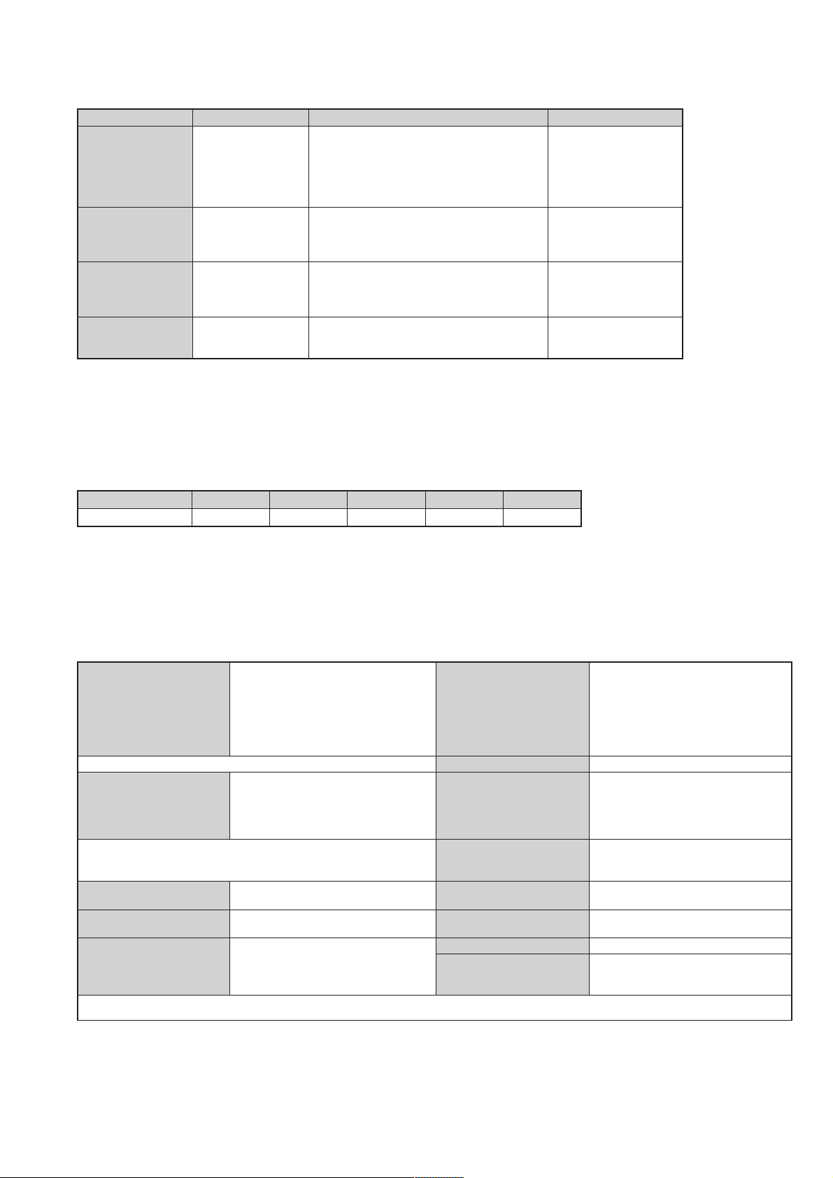
Section Title Page Section Title Page
Specifications .................... 3
Connectors .................... 5
Self Diagnostic Software .................... 6
1. GENERAL
Switching On the TV and
Automatically Tuning .................... 7
Introducing the Menu System .................... 8
Teletext .................... 10
Connecting Optional Equipment.................... 10
Using Optional Equipment .................... 10
Troubleshooting .................... 11
2. DISASSEMBLY
KV-21LT1
2-1. Rear Cover Removal .................... 12
2-2. A Board PWB Removal 1 .................... 12
2-3. A Board PWB Removal 2 .................... 12
2-4. Service Position .................... 12
2-5. Wire Dressing .................... 12
2-6. Picture Tube Removal .................... 13
KV-21FT2
2-7. Rear Cover Removal .................... 14
2-8. Chassis Removal .................... 14
2-9. Service Position .................... 14
2-10. Wire Dressing .................... 14
2-11. Picture Tube Removal .................... 15
3. SET-UP ADJUSTMENTS
3-1. Beam Landing .................... 16
3-2. Convergence .................... 17
3-3. Focus Adjustment .................... 19
3-4. Screen (G2), White Balance .................... 19
4. CIRCUIT ADJUSTMENTS
4-1. Electrical Adjustments .................... 20
4-2. Test Mode 2 .................... 22
5. DIAGRAMS
5-1. Circuit Board Location .................... 24
5-2. Block Diagrams .................... 25
5-3. Schematic Diagrams and
Printed Wiring Boards .................... 24
* C Board .................... 29
* A Board .................... 31
5-4. Semiconductors .................... 39
5-5. IC Blocks .................... 41
6. EXPLODED VIEWS
6-1. Chassis (KV-21LT1) .................... 42
Chassis (KV-21FT2) .................... 44
6-2. Picture Tube(KV-21LT1) .................... 43
Picture Tube(KV-21FT2) .................... 45
7. ELECTRICAL PARTS LIST .................... 46
CAUTION
SHORT CIRCUIT THE ANODE OF THE PICTURE TUBE AND THE
ANODE CAP TO THE METAL CHASSIS, CRT SHIELD, OR THE
CARBON PAINTED ON THE CRT, AFTER REMOVAL OF THE
ANODE CAP.
WARNING !!
AN ISOLATION TRANSFORMER SHOULD BE USED DURING ANY
SERVICE WORK TO AVOID POSSIBLE SHOCK HAZARD DUE TO
LIVE CHASSIS, THE CHASSIS OF THIS RECEIVER IS DIRECTLY
CONNECTED TO THE POWER LINE.
SAFETY-RELATED COMPONENT WARNING !!
£
COMPONENTS IDENTIFIED BY SHADING AND MARKED
THE SCHEMATIC DIAGRAMS, EXPLODED VIEWS AND IN THE
PARTS LIST ARE CRITICAL FOR SAFE OPERATION. REPLACE
THESE COMPONENTS WITH SONY PARTS WHOSE PART
NUMBERS APPEAR AS SHOWN IN THIS MANUAL OR IN
SUPPLEMENTS PUBLISHED BY SONY.
ON
ATTENTION
APRES AVOIR DECONNECTE LE CAP DE’LANODE,
COURT-CIRCUITER L’ANODE DU TUBE CATHODIQUE ET CELUI
DE L’ANODE DU CAP AU CHASSIS METALLIQUE DE L’APPAREIL,
OU AU COUCHE DE CARBONE PEINTE SUR LE TUBE
CATHODIQUE OU AU BLINDAGE DU TUBE CATHODIQUE.
ATTENTION !!
AFIN D’EVITER TOUT RISQUE D’ELECTROCUTION PROVENANT
D’UN CHÁSSIS SOUS TENTION, UN TRANSFORMATEUR
D’ISOLEMENT DOIT ETRE UTILISÈ LORS DE TOUT DÈPANNAGE
LE CHÁSSIS DE CE RÈCEPTEUR EST DIRECTMENT RACCORDÈ
Á L’ALIMENTATION SECTEUR.
ATTENTION AUX COMPOSANTS RELATIFS Á
LES COMPOSANTS IDENTIFIÈS PAR UNE TRAME ET PAR UNE
£
MARQUE
EXPLOSÈES ET LES LISTES DE PIECES SONT D’UNE IMPORTANCE CRITIQUE POUR LA SÈCURITÈ DU FONCTIONNEMENT,
NE LES REMPLACER QUE PAR DES COMPSANTS SONY DONT LE
NUMÈRO DE PIÈCE EST INDIQUÈ DANS LE PRÈSENT MANUEL
OU DANS DES SUPPLÈMENTS PUBLIÈS PAR SONY.
SUR LES SCHÈMAS DE PRINCIPE, LES VUES
LA SECURITÈ!!
2
LEDOMMETI
metsySnoisiveleT egarevoClennahC metsySroloC
hcnerFI,L,H/G/B
hsinapSH/G/B
TRIOK/D,H/G/B
KUI96B-12BFHU:I
01F-2F,21E-2E:FHV
96E-12E:FHU
Q-B,02S-1S,30S-10S:VTELBAC
14S-12S:REPYH
96F-12F,01F-20FL
MACES,LAP
85.3CSTN,34.4CSTN
)NIOEDIV(
96B-12B:FHUI
21E-2E:FHV
96E-12E:FHU
02S-1S,30S-10S:VTELBAC
14S-12S:REPYH
21R-10R,21E-2E:FHV
96R-12R,96E-12E:FHU
02S-1S,30S-10S:VTELBAC
14S-12S:REPYH
MACES,LAP
85.3CSTN,34.4CSTN
)NIOEDIV(
MACES,LAP
85.3CSTN,34.4CSTN
)NIOEDIV(
MACES,LAP
85.3CSTN,34.4CSTN
)NIOEDIV(
ledoM K2TF12-VK B1TL12-VK
noitpmusnoCrewoPW55W55W55W55W67
nortinirTDFyalpsiDtalF
ebuTerutciP
]RAER[slanimreTtuptuO/tupnI
rotcennocoruEnip-12:1
)dradnatsCELENEC(
tupnioediVkcajonohp seirosseccAdeilppuS
tupnioiduAkcajonohp serutaeFrehtO
kcajenohpdaeHkcajinimoerets
)yllanogaid
.BGRrofstupnI
]TNORF[slanimreTtuptuO/tupnI
)sehcni12(mc55.xorppA
derusaemerutcipmc15.xorppA(
noitcelfedeerged011
E1TL12-VK K1TL12-VK U1TL12-VK
.slangisoediVdnaoiduArofstupnI
snoisnemiD
.slangisoiduAdnaoediVVTfostuptuO
thgieW
tuptuodnuoS
stnemeriuqeRrewoPV042-022
metsyslortnocetomeRlortnocderarfnI
stnemeriuqerrewoP
)rewoPcisuM(W8x1
:U1TL12/K1TL12/E1TL12/B1TL12
)onoMSMR(W4x1
:K2TF12
)rewoPcisuM(W6x2
)onoMSMR(W3x2
:U1TL12/K1TL12/E1TL12/B1TL12
mm784x874x415xorppA
:K2TF12
mm774x084x884xorppA
:U1TL12/K1TL12/E1TL12/B1TL12
gk42xorppA
gk1.62xorppA:K2TF12
)1(rednammoCetomeR788-MR
)2(yrettab6RdetangisedCEI
,kniltramS,remiTpeelS,txeteleT
noitcetedotuAmetsysVT
cdV3
noitangisedCEIseirettab2
)AAezis(6R
.ecitontuohtiwegnahcottcejbuserasnoitacificepsdnangiseD
3
metI
emaNledoM
K2TF12-VK B1TL12-VK E1TL12-VK K1TL12-VK U1TL12-VK
bmoClaPFFOFFOFFOFFOFFO
PIPFFOFFOFFOFFOFFO
ytiroirPBGRFFONONOFFONO
xoBrefooWFFOFFOFFOFFOFFO
1tracSNONONONONO
2tracSFFOFFOFFOFFOFFO
)3(nitnorFFFOFFOFFOFFOFFO
4tracSFFOFFOFFOFFOFFO
rotcejorPFFOFFOFFOFFOFFO
edom9:61niBKAFFOFFOFFOFFOFFO
G/BmroNNONONONOFFO
ImroNFFONOFFOFFONO
K/DmroNNOFFONOFFOFFO
SUAmroNFFOFFOFFOFFOFFO
LmroNFFONOFFOFFOFFO
TASmroNFFOFFOFFOFFOFFO
MmroNFFOFFOFFOFFOFFO
txeteleTNONONONONO
oeretSmaciNFFOFFOFFOFFOFFO
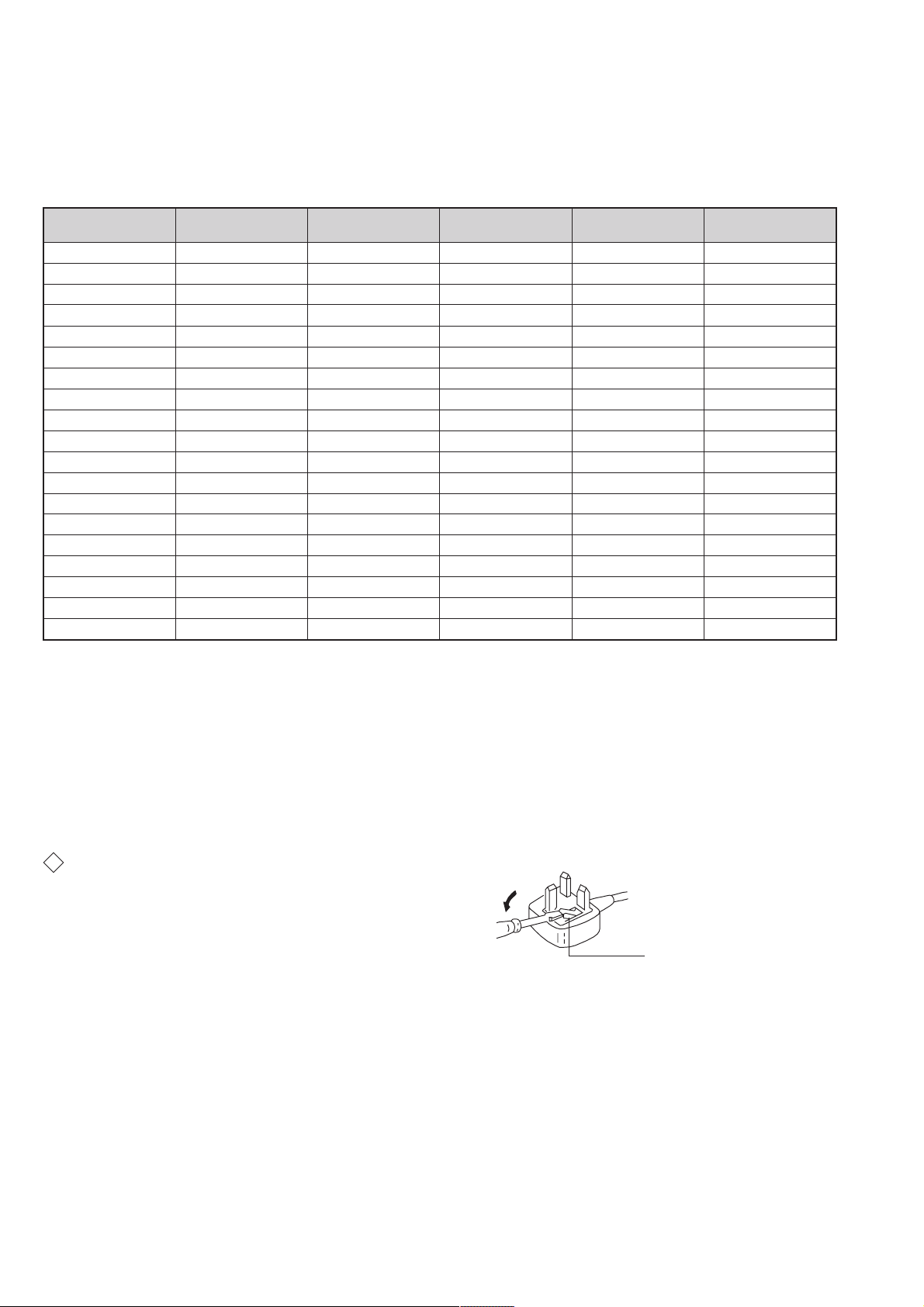
WARNING (UK Models only)
The flexible mains lead is supplied connected to a B.S. 1363 fused plug
having a fuse of 5 AMP rating. Should the fuse need to be replaced, use
a 5 AMP FUSE approved by AST A to BS 1362, ie one that carries the
ASA
mark.
T
IF THE PLUG SUPPLIED WITH THIS APPLIANCE IS NOT SUITABLE
FOR THE OUTLET SOCKETS IN YOUR HOME, IT SHOULD BE CUT
OFF AND AN APPROPRIATE PLUG FITTED. THE PLUG SEVERED
FROM THE MAINS LEAD MUST BE DESTROYED AS A PLUG WITH
BARED WIRES IS DANGEROUS IF ENGAGED IN A LIVE SOCKET.
When an alternative type of plug is used, it should be fitted with a
5 AMP FUSE, otherwise the circuit should be protected by a 5 AMP
FUSE at the distribution board.
How to replace the fuse.
Open the fuse compartment with
a screwdriver blade and replace
the fuse.
FUSE
4
21 pin connector
21
19
17
15
13
11
9
7
5
3
1
20
18
16
14
12
10
8
6
4
2
Pin No 1 2 4 Signal Signal level
1 Audio output B
2
3
4 Ground (audio)
5 Ground (blue)
6 Audio input A
7 Blue input 0.7 +/- 3dB, 75 ohms positive
8 Function select
9 Ground (green)
10 Open
11 Green Green signal : 0.7 +/- 3dB, 75 ohms,
12 Open
13 Ground (red)
14 Ground (blanking)
15
_ (S signal Chroma
16 Blanking input
17 Ground (video
18 Ground (video
19 Video output 1V +/- 3dB, 75ohms, positive sync 0.3V
20
_ Video input
21 Common ground
(right)
Audio output B
(right)
Audio output A
(left)
(left)
(AV control)
_ _ Red input 0.7 +/- 3dB, 75 ohms, positive
input)
(Ys signal)
output)
input)
_ _ Video input 1V +/- 3dB, 75ohms, positive sync 0.3V
Y (S signal)
(plug, shield)
Standard level : 0.5V rms
Output impedence : Less than 1kohm*
Standard level : 0.5V rms
Output impedence : More than 10kohm*
Standard level : 0.5V rms
Output impedence : Less than 1kohm*
Standard level : 0.5V rms
Output impedence : More than 10kohm*
High state (9.5-12V) : Part mode
Low state (0-2V) : TV mode
Input impedence : More than 10K ohms
Input capacitance : Less than 2nF
positive
0.3 +/- 3dB, 75 ohms, positive
High state (1-3V) Low state (0-0.4V)
Input impedence : 75 ohms
(-3+10dB)
(-3+10dB)
1V +/- 3dB, 75ohms, positive sync 0.3V
(-3+10dB)
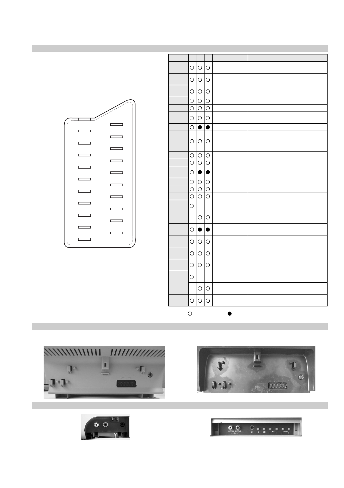
Rear Connection Panel
KV-21LT1
Front Connection Panel
KV-21LT1
Connected Not Connected (open) * at 20Hz - 20kHz
KV-21FT2
KV-21FT2
5
FE-2 SELF DIAGNOSTIC SOFTWARE
The identification of errors within the FE-2 chassis is triggered in one of two ways :- 1: Busy or 2: Device failure to respond to IIC. In the event of
one of these situations arising the software will first try to release the bus if busy (Failure to do so will report with a continuous flashing LED) and
then communicate with each device in turn to establish if a device is faulty. If a device is found to be faulty the relevant device number will be
displayed through the LED (Series of flashes which must be counted) See table 1., non fatal errors are reported using this method.
Each time the software detects an error it is stored within the NVM. See T able 2.
Table 1
egasseMrorrE
rorreoN00
devreseR10
)noitcetorPtnerruCrevO(PCO20
devreseR30
cnySlacitreVoN40
BKAelbatsnU50
norewoptawolsenilatadro/dnakcolcsubCII60
norewoptaegdelwonkcasubCIIonMVN70
desUtoN80
norewoptaegdelwonkcaonrenuT90
desutoN01
NOrewoPtaegdelwonkcaonrellortnocelgnuJ11
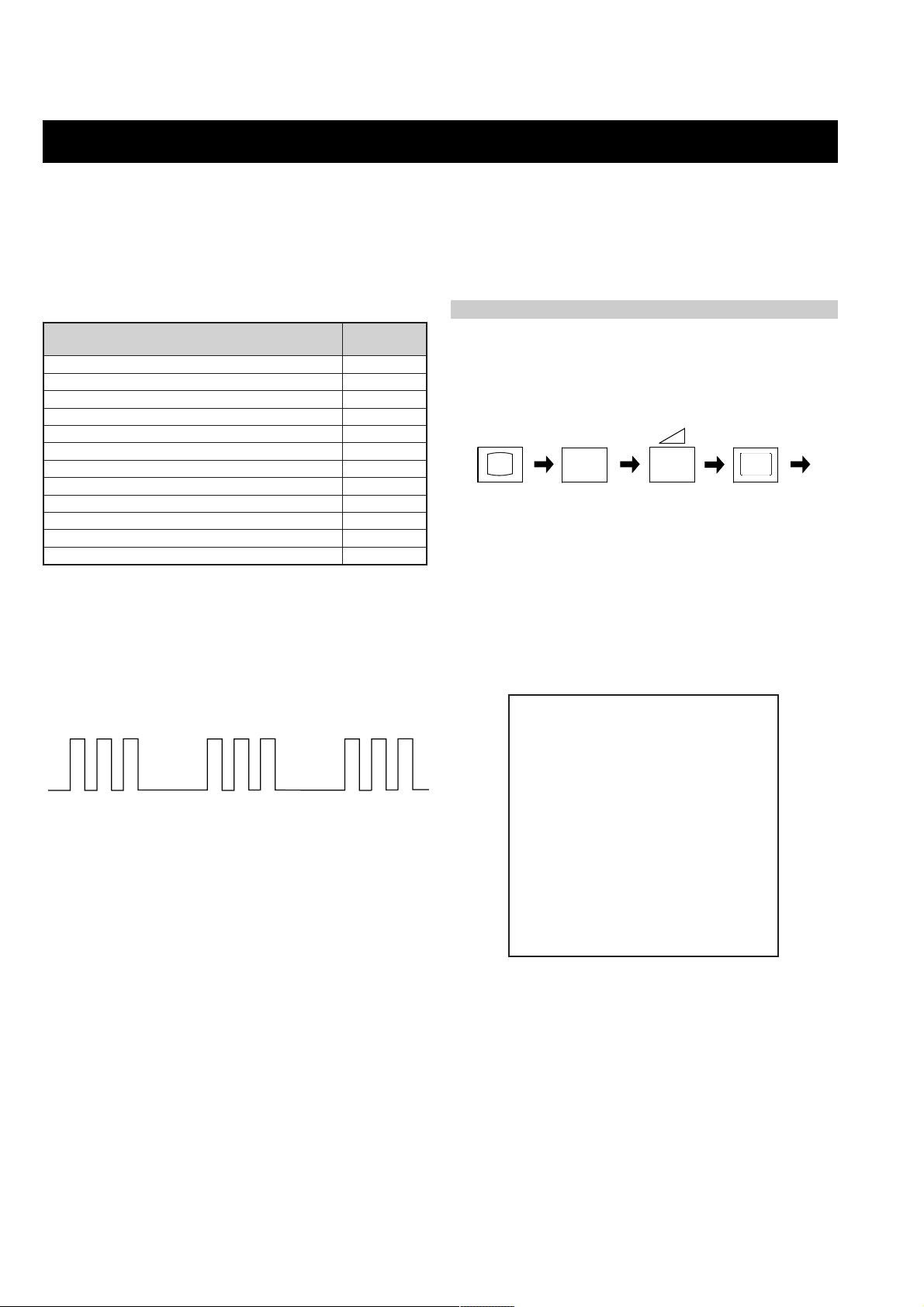
Flash Timing Example : e.g. error number 3
StBy LED
ON
OFF
ON ON
OFF
How to enter into T able 2
DEL
edoC
1. Turn on the main power switch of the TV set and enter into the
‘Stanby Mode’.
2. Press the following sequence of buttons on the Remote
Commander.
i+
(ON SCREEN (DIGIT 5) (VOLUME -) (TV)
DISPLAY)
5
-
3. The following table will be displayed indicating the error count.
Table 2
UNEMRORRE
20E
30E
40E
50E
60E
70E
80E
90E
01E
11E
PCO
A/NPVO
CNYSV
RKI
CII
MVN
ELGNUJ
RENUT
PDNUOS
V8
)552,0(
0
)552,0(
0
)552,0(
0
)552,0(
0
)552,0(
0
)552,0(
0
)552,0(
0
)552,0(
0
)552,0(
0
)552,0(
0
GNIKROW
EMIT
SRUOH
SETUNIM
Note: T o clear the error count data press ‘80’ on the Remote
commander.
6
0
0

SECTION 1 GENERAL
K
OK
Confirm
aerial is connected
Please confirm that
that the aerial is connected. Ensure the aerial is connected
and then press the OK button to start the automatic
A new menu appears on the screen asking you to check
5
Auto Tuning
System: B/G
Programme: 01
Searching...
Channel: C21
The TV starts to automatically search and store all
This procedure could take some minutes. Please be
tuning.
available channels (TV Broadcast) for you.
patient and do not press any button. Otherwise the
automatic tuning will not be completed.
K
Programme Sorting
Programme:
01 TVE
02 TVE2
03 TV3
04 C33
05 C27
06 C58
Select channel:
After all available channels are captioned and stored,
6
If you do not wish to change the channel order, go to
a)
the Programme Sorting menu appears automatically
on the screen enabling you to change the order in
which the channels appear on the screen.
K
OK
MENU
Exit:
Programme Sorting
If you wish to change the channel order:
1 Press the or button to select the programme
b)
step 7.
OK
MENU
Programme:
01 TVE
02 TVE2
03 TV3
04 C33
05 C27
06 C58 05 C27
Select new position:
Exit:
number with the channel (TV Broadcast) you wish
programme number position for your selected
2 Press the or button to select the new
3 Repeat steps b)1 and b)2 if you wish to change
to rearrange, then press the button.
channel (TV Broadcast), then press .
MENU
MENU
the order of the other channels.
Press the MENU button to remove the menu from the
screen.
7
Your TV is now ready for use
First Time Operation
8
GB
7
The operating instructions mentioned here are partial abstracts from the ‘Operating
Instruction Manual’. The page numbers of the ‘Operating Instruction Manual’ remain
as in the manual.
Language menu
Language
English
Español
Français
K
Italiano
Magyar
OK
Select Language:
Nederlands
Country
K
OK
Select country:
Magyarország
Polska
România
-
Бългapия
Česká rep.
OK
button to confirm your
on the TV set.
OK
menu appears automatically on the TV
Select “-“ instead of a country
• If the country in which you want to use the TV set
The first time you switch on your TV, a sequence of menu screen appear on the TV enabling
you to: 1) choose the language of the menu screen, 2) choose the country in which you wish
to operate the TV, 3) search and store all available channels (TV Broadcast) and 4) change
the order in which the channels (TV Broadcast) appear on the screen.
However, if you need to change the language menu, change or repeat the tuning (e.g. when
you move house) or rearrange again the order of the channels afterwards, you can do that
by selecting the appropriate menu in the (Set Up). For more information, refer to the
“Menu Guide” section of this instruction manual. You can also do that by pressing the
Auto Start Up Button
Connect the TV plug to the mains socket (220-240V AC,
Switching On the TV and Automatically Tuning
1
displays automatically on the TV screen.
50Hz)
Press the on/off button on the TV set to turn on the TV.
The first time you press this button, a
the language, then press the
selection. From now on all the menus will appear in the
Press the or button on the remote control to select
2
selected language.
Country
The
3
screen. Press the or button to select the country in
which you will operate the TV set, then press the
button to confirm your selection.
• If you do not want your channels (TV Broadcast)
does not appear in the list.
stored in a given channel sequence starting from
programme position 1.
K
continued...
OK
No
Yes
automatic tuning?
Do you want to start
First Time Operation
.
Yes
menu appears on the screen. Press the
Auto Tuning
button to select
The
OK
4
7
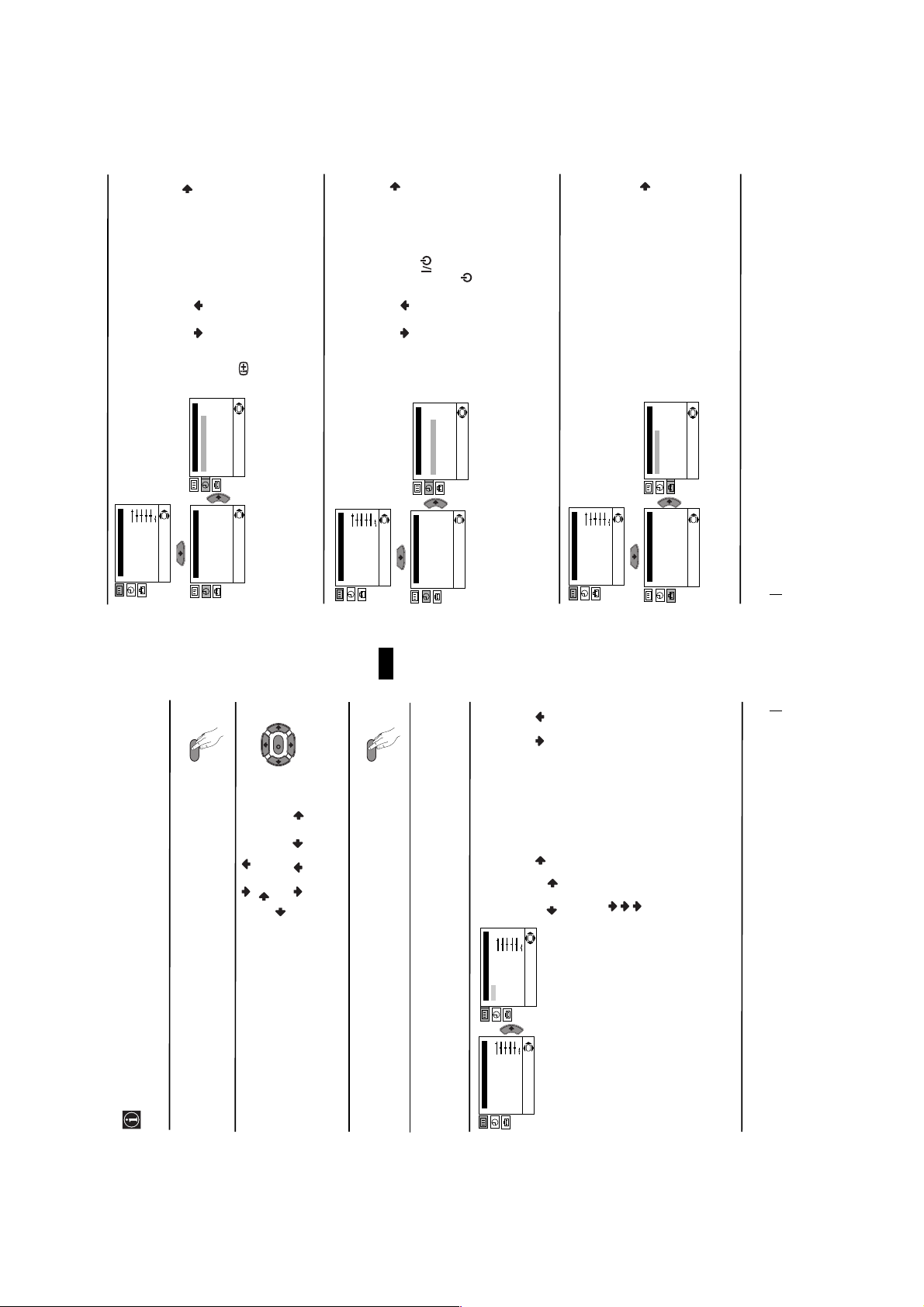
SLEEP TIMER
The “Sleep Timer” option in the “Timer” menu
allows you to select a time period for the TV to
switch itself automatically into the standby
mode.
To do that: after selecting the option press ,
then press or to set the time period delay
(max. of 4 hours) and finally press OK to store. • While watching the TV, you can press the
button on the remote control to display the
time remaining.
• One minute before the TV switches itself into
standby mode, the time remaining is displayed on
the TV screen automatically.
OK
Timer
Sleep Timer: Off
On Timer: i Off
on the remote
control. After the selected length of time the TV
switches on automatically.
• The standby indicator on the TV set flashes
regularly to indicate that “On Timer” is active.
• Any loss of power will cause these settings to be
ON TIMER
The “On Timer” option in the “Timer” menu
allows you to select a time period for the TV to
switch itself automatically on from standby
mode.
To do that: after selecting the option press ,
then press or to set the time period delay
(max. 12 hours) and press OK to store. Finally
press the standby button
Timer
Sleep Timer: Off
On Timer: Off
cleared.
OK
continued...
LANGUAGE / COUNTRY
The “Language/Country” option in the “Set
Up” menu allows you to select the language
that the menus are displayed in. It also allows
you to select the country in which you wish to
operate the TV set.
To do that: after selecting the option, press
and then proceed in the same way as in the
steps 2 and 3 of the section “Switching On the
TV and Automatically Tuning”.
OK
Set Up
Language/Country
Auto Tuning
Programme Sorting
Manual Programme Preset
Advanced Features
OK
Picture Adjustment
Mode: Personal
Contrast
Brightness
Colour
Sharpness
Hue
Reset
Level 1 Level 2 Level 3 / Function
Timer
MENU
OK
Sleep Timer: Off
On Timer: Off
Picture Adjustment
Mode: Personal
Contrast
Brightness
Colour
Sharpness
OK
Hue
Reset
OK
Timer
Sleep Timer: Off
On Timer: Off
Picture Adjustment
Mode: Personal
Contrast
Brightness
Colour
Sharpness
OK
Hue
Reset
Set Up
Language/Country
Auto Tuning
Programme Sorting
OK
Manual Programme Preset
Advanced Features
Menu System
10
GB
9
K
MENU
//or.
Personal (for individual settings).
Live (for live broadcast programmes).
.
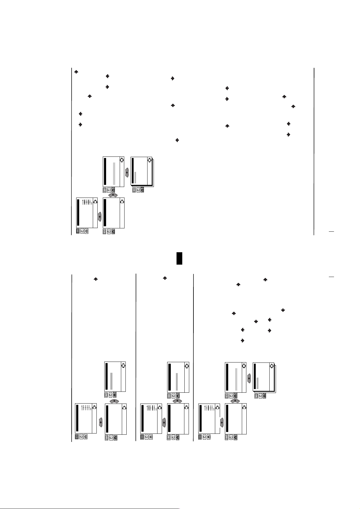
PICTURE ADJUSTMENT
The “Picture Adjustment” menu allows you to
alter the picture adjustments.
or to adjust it and finally press OK to
To do that: after selecting the item you want to
alter press , then press repeatedly / /
store the new adjustment.
This menu also allows you to customise the
picture mode based on the programme you are
OK
Movie (for films).
watching:
continued...
Menu System
Your TV uses an on-screen menu system to guide you through the operations. Use the
following buttons on the Remote Control to operate the menu system:
Introducing and Using the Menu System
Press the MENU button to switch the first level menu on.
1
• To highlight the desired menu or option, press or.• To enter to the selected menu or option, press .
• To return to the last menu or option, press
• To alter settings of your selected option, press
2
• To confirm and store your selection, press OK.
Press the MENU button to remove the menu from the screen.
3
Level 1 Level 2 Level 3 / Function
Menu Guide
8
Picture Adjustment
Mode: Personal
Contrast
Brightness
Colour
Picture Adjustment
Mode: Personal
Contrast
Brightness
Colour
Sharpness
Sharpness
Hue
Reset
Hue
Reset
OK
• Brightness, Colour and Sharpness can only be alterated if “Personal” mode is selected.
• Hue is only available for NTSC colour signal (e.g: USA video tapes).
• Select Reset and press OK to reset the picture to the factory preset levels.
continued...
to select a letter, number or
r
cable channels). Next press . After that,
press the number buttons to enter directly the
channel number of the TV Broadcast or the
tuning (“C” for terrestrial channels or “S” for
Then press or to select the channel
3 After selecting the Channel option, press .
OK
Picture Adjustment
Mode: Personal
Contrast
Brightness
Colour
Sharpness
Hue
Reset
Level 1 Level 2 Level 3 / Function
channel of the VCR signal. If you do not
know the channel number, press or to
search for it. When you tune the desired
channel, press OK twice to store.
Set Up
Language/Country
Auto Tuning
Programme Sorting
Manual Programme Preset
Advanced Features
Set Up
Language/Country
Auto Tuning
Programme Sorting
Manual Programme Preset
Advanced Features
Normally the automatic fine tuning (AFT) is
channels.
operating, however you can manually fine
Repeat all the above steps to tune and store more
OK
OK
tune the TV to obtain a better picture
b)
OK
01
B/G
C 21
--TVEOnNo
Off
Manual Programme Preset
Programme:
System:
Channel:
Label:
AFT:
Skip:
Decoder:
Confirm
Broadcast) you wish to fine tune, select the
reception in the case that the picture is
distorted.
To do that: while watching the channel (TV
the programme number you want to skip.
When the programme you want to skip
or to adjust the fine tuning between -15
and +15. Finally press OK twice to store.
when they are selected with the PROGR +/-
AFT option and press . Next press
buttons.
Skip any unwanted programme numbers
To do that: Highlighting the Programme
c)
and press . Next press or to select
appears on the screen, select the Skip option
option, press the PROGR +/- button to select
GB
Yes. Finally press OK twice to confirm and
store.
Label a channel using up to five characters.
the programme number with the channel
you wish to name. When the programme you
want to name appears on the screen, select
instead of “Yes” in the step above.
To cancel this function afterwards, select “No”
option, press the PROGR +/- button to select
To do that: Highlighting the Programme
d)
the Label option and press . Next
press o
the same way. After selecting all the
“-“ for a blank. Press to confirm this
character. Select the other four characters in
characters, press OK twice to store.
Menu System
12
11
continued...
Menu System
AUTO TUNING
The “Auto Tuning” option in the “Set Up”
menu allows you to automatically search for
and store all available TV channels.
To do that: after selecting the option, press
and then proceed in the same way as in TV
steps 4 and 5 of the section “Switching On the
TV and Automatically Tuning”.
OK
Set Up
Language/Country
Auto Tuning
Programme Sorting
Manual Programme Preset
Advanced Features
Picture Adjustment
Mode: Personal
Contrast
Brightness
Colour
Sharpness
OK
Hue
Reset
Set Up
Language/Country
Auto Tuning
Programme Sorting
OK
Manual Programme Preset
Advanced Features
Level 1 Level 2 Level 3 / Function
PROGRAMME SORTING
The “Programme Sorting” option in the “Set
Up” menu allows you to change the order in
which the channels (TV Broadcast) appear on
the screen.
To do that: after selecting the option, press
and then proceed in the same way as in step 6 b)
of the section “Switching On the TV and
Picture Adjustment
Mode: Personal
Contrast
Brightness
Colour
Sharpness
Hue
Reset
Automatically Tuning”.
Set Up
Language/Country
Auto Tuning
Programme Sorting
Manual Programme Preset
Advanced Features
OK
Set Up
Language/Country
Auto Tuning
Programme Sorting
Manual Programme Preset
Advanced Features
MANUAL PROGRAMME PRESET
The “Manual Programme Preset” option in the
“Set Up” menu allows you to:
OK
OK
Picture Adjustment
Mode: Personal
Contrast
Brightness
Colour
Sharpness
9
Preset channels or a video input source one
a)
Hue
Reset
Preset” option, press then with
Programme option highlighted press .
Press or to select on which
by one to the programme order of your
choice. To do that:
1 After selecting the ”Manual Programme
Set Up
OK
Set Up
Language/Country
programme number you want to preset the
channel (for VCR, select programme number
“0”). Then press .
OK
Manual Programme Preset
Advanced Features
OK
Manual Programme Preset
Advanced Features
Manual Programme Preset
Language/Country
Auto Tuning
Programme Sorting
Auto Tuning
Programme Sorting
2 After selecting the System option, press .
01
B/G
C 21
--TVEOnNo
Off
Programme:
System:
Channel:
Label:
AFT:
Skip:
Decoder:
Confirm
Then press or to select the TV
OK
Broadcast system (B/G for western European
countries or D/K for eastern European
countries). Then press .
C
Decoder
VCR
8mm/Hi8/DVC
camcorder
2
1
“PlayStation”**
AB
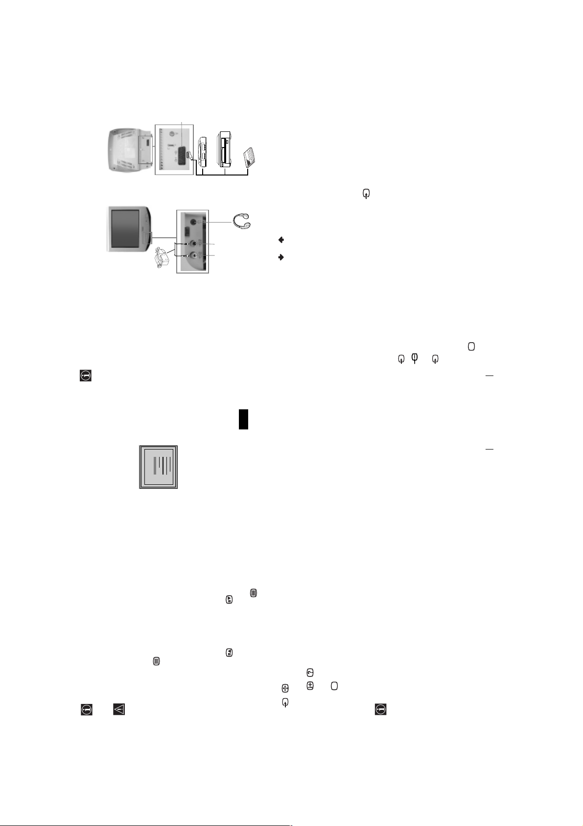
Using the following instructions, you can connect a wide range of optional equipment to
Connecting Optional Equipment
your TV set. (Connecting cables are not supplied).
Connecting a VCR:
To connect a VCR, please refer to
the section “Connecting the
aerial and VCR” of this instruction
manual. We recommend you
connect your VCR using a scart
lead. If you do not have a scart
lead, tune in the VCR test signal
to TV programme number “0”.
by using “Manual Programme
Preset” option. (for details how
to manual programme, see page
11, step a).
Also refer to your VCR
instruction manual to find out
how to find the output channel
of your VCR.
If you have connected a decoder
to a VCR which supports
Smartlink feature:
Select the “Manual Programme Preset” option in the “Set Up” menu and after entering in the
“Decoder*” option, select “On” (by using or ) to each scrambled channel.
*This option is only available depending the country you have selected in the “Country” menu.
GB
1 • Audio / video input signal through the Scart connector C
Connect your equipment to the designated TV socket, as indicated above.
To watch the picture of the connected equipment, press the button repeatedly until the
** “PlayStation” is a product of Sony Computer Entertainment, Inc.
** “PlayStation” is a trademark of Sony Computer Entertainment, Inc.
Using Optional Equipment
1
2
correct input symbol appears on the screen.
•RGB input signal through the Scart connector C. This symbol appears only
Symbol Input Signals
if a RGB source has been connected.
2 • Video input signal through the phono socket A and Audio input signal
Switch on the connected equipment.
Press button on the remote control to return to the normal TV picture.
through B.
3
Additional Information
4
16
25
98
25
98
25
98
25
98
25
98
25
98
25
98
25
98
153
101
153
101
153
101
153
101
153
101
153
101
153
101
153
101
TELETEXT
TELETEXT
TELETEXT
TELETEXT
TELETEXT
TELETEXT
TELETEXT
TELETEXT
Index
Programme
News
Sport
Weather
Index
Programme
News
Sport
Weather
Index
Programme
News
Sport
Weather
Index
Programme
News
Sport
Weather
Index
Programme
News
Sport
Weather
Index
Programme
News
Sport
Weather
Index
Programme
News
Sport
Weather
Index
Programme
News
Sport
Weather
Teletext is an information service transmitted by most TV stations. The index page of the
Teletext
Make sure to use a channel (TV Broadcast) with a strong signal, otherwise teletext errors
teletext service (usually page 100) gives you information on how to use the service. To
operate teletext, use the remote control buttons as indicated below.
After select the channel (TV Broadcast) which carries the teletext you wish
to view, press .
Input 3 digits for the page number, using the numbered buttons.
• If you have made a mistake, retype the correct page number.
may occur.
To Switch On Teletext :
• If the counter on the screen continues searching, it is because this page is not available. In that case,
To Select a Teletext page:
input another page number
To access the next or preceding page:
Whilst you are viewing teletext, press . Press it again to cancel teletext mode.
Press PROGR + ( ) or PROGR - ().
To superimpose teletext on to the TV:
Some teletext pages have sub-pages which follow on automatically. To stop them, press
To freeze a teletext page:
/ . Press it again to cancel the freeze.
Fastext service lets you access pages with one button push.
Press / . Press it again to conceal the information.
To reveal concealed information (e.g: answer to a quiz):
Press .
To Switch Off Teletext:
While you are in Teletext mode and Fastext is broadcast, a colour coded menu appears at
Fastext
the bottom of the teletext page. Press the colour button (red, green, yellow or blue) to access
the corresponding page.
15
Teletext
10
Solution
•Check the aerial connection.
• Plug the TV in and press the button on the front of
TV.
Adjustment” menu and select “Reset” to return to the
•If the standby indicator is on, press button on
the remote control.
•Using the menu system, select the “Picture
Adjustment” menu and select “Reset” to return to
factory settings.
•Check that the optional equipment is on and press the
button repeatedly on the remote control until the
correct input symbol is displayed on the screen.
factory settings.
• Press the +/- button on the remote control.
• Using the menu system, select the “Picture
• Turn off any equipment connected to the Scart
connector on the rear of the TV.
• Using the menu system, select the “Picture Rotation”
Programme Preset” menu and adjust Fine Tuning
option in the “Advanced Features” menu to correct the
picture slant.
• Using the menu system, select the “Manual
(AFT) to obtain better picture reception.
• Using the menu system, select the “Noise Reduction”
option in the “Advanced Features” menu and select
“On” to reduce the noise in the picture.
• Replace the batteries.
• Contact to your nearest Sony service centre.
Here are some simple solutions to the problems which may affect the picture and sound.
Troubleshooting
Problem
No picture (screen is dark) and no
sound.
Poor or no picture (screen is dark),
but good sound.
No picture or no menu information
from the equipment connected to the
Scart connector.
Good picture, no sound.
No colour on colour programmes.
Distorted picture when changing
programmes or selecting teletext.
Picture slanted (only for
KV-21LT1K)
Noisy picture when viewing a TV
channel.
11
In case of problems, have your TV serviced by qualified personnel. Never open the
casing yourself.
Remote control does not function.
The standby indicator on the TV
flashes even though the “On Timer”
Additional Information
18
KV-21LT1
SECTION 2 DISASSEMBLY
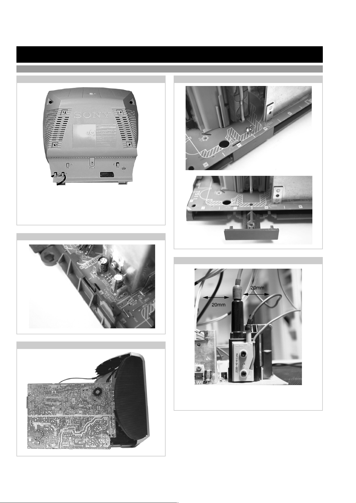
2-1. Rear Cover Removal
=>
<=
=> <=
Release the mains power cable from its securing posts.
Remove the rear cover fixing screws indicated. Pull the rear
cover away from the front beznet until clear of chassis.
Note : Use a cross-head screwdriver with a blade length of at
least 200mm.
2-3. A Board PWB Removal [ Step 2 ]
2-2. A Board PWB Removal [ Step 1 ]
Remove FBT
support bracket.
<=
<=
Remove screw .
Release the 2 securing
clips located at either
side of the chassis and
slide the PWB clear of
the bracket.
2-4. Service Position
Place the A Board PWB in the
position indicated to carry out
servicing.
<=
2-5. Wire Dressing
Ensure that all wires do not touch heat-sinks and high
temperature hot spots. All wires must be kept at a minimum
distance of 20mm away from the EHT lead.
12
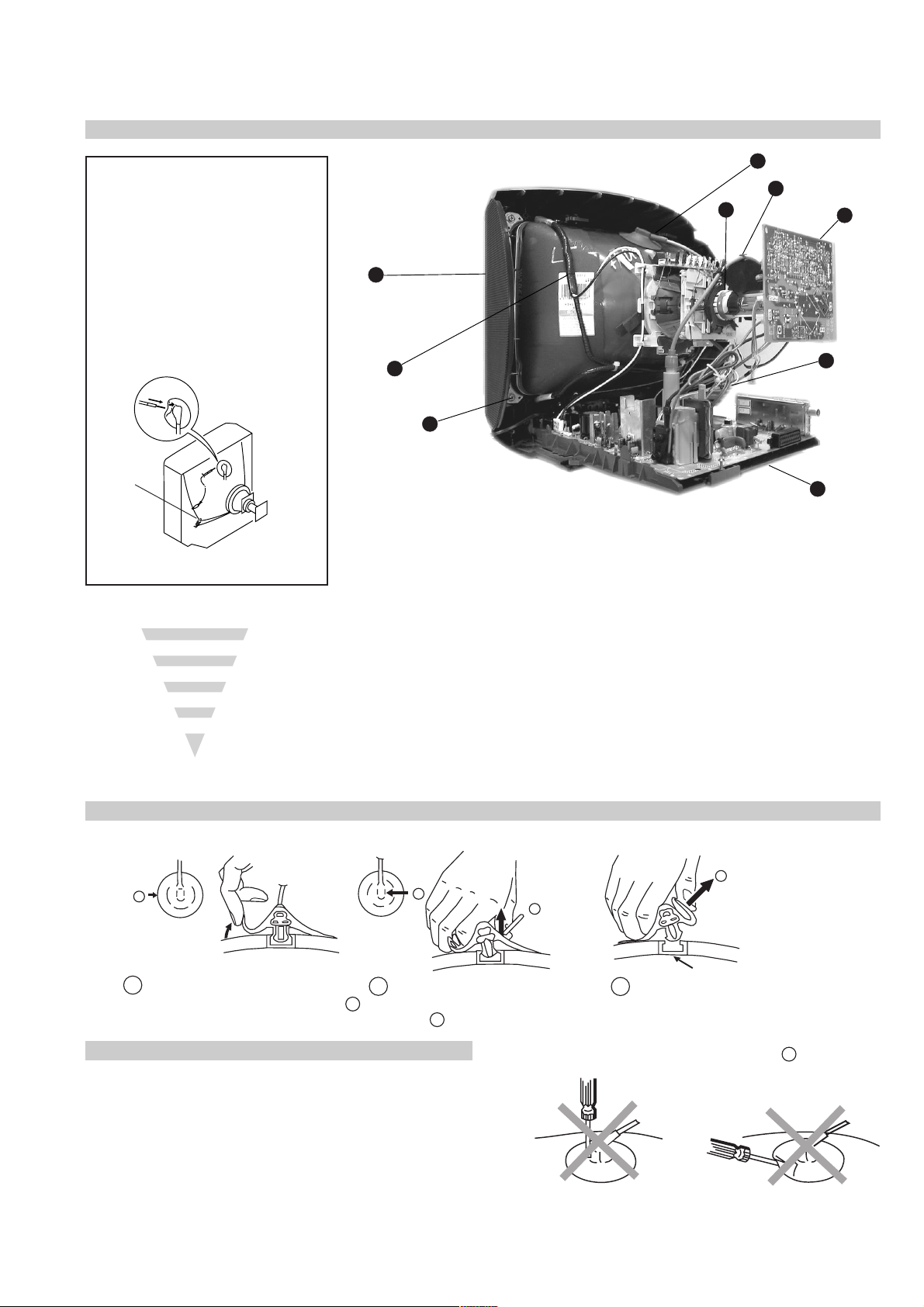
2-6. Picture Tube Removal
WARNING:
BEFORE REMOVING
THE ANODE CAP
High voltage remains in the CRT even
after the power is disconnected. To
avoid electric shock, discharge CRT
before attempting to remove the anode
cap. Short between anode and CRT
coated earth ground strap.
Coated Earth
Ground Strap
1
2
6
7
9
8
4
3
5
1. Discharge the anode of the CRT and remove the anode cap.
2. Release the EHT lead from its CR T support bracket.
3. Unplug all interconnecting leads from the Deflection yoke,
degaussing coils and CRT grounding strap.
4. Remove the C Board from the CRT .
5. Remove the chassis assembly.
6. Loosen the Deflection yoke fixing screw and remove.
7. Place the set with the CRT face down on a cushion.
8. Unscrew the four CRT fixing screws [ located on each CRT
corner ] and remove the CRT .
9. Remove the Degaussing Coils.
Remove the CRT grounding strap and spring tentioners.
[Take care not to handle the CRT by the neck.]
Removal of the Anode-Cap
* REMOVING PROCEDURES.
a
1
Turn up one side of the rubber cap in
the direction indicated by the arrow a
b
2 Using a thumb pull up the rubber cap
firmly in the direction indicated by the
arrow b
How to handle the Anode-Cap
1. To prevent damaging the surface of the anode-cap do not use
sharp materials.
2. Do not apply too great a pressure on the rubber, as this may cause
damage to the anode connector.
3. A metal fitting called a shatter hook terminal is fitted inside the
rubber cap.
4. Do not turn the rubber foot over excessively, this may cause damage
if the shatter hook sticks out.
c
b
Anode button
3 When one side of the rubber cap is
separated from the anode button, the
anode-cap can be removed by turning
up the rubber cap and pulling it up in
the direction of the arrow c
13
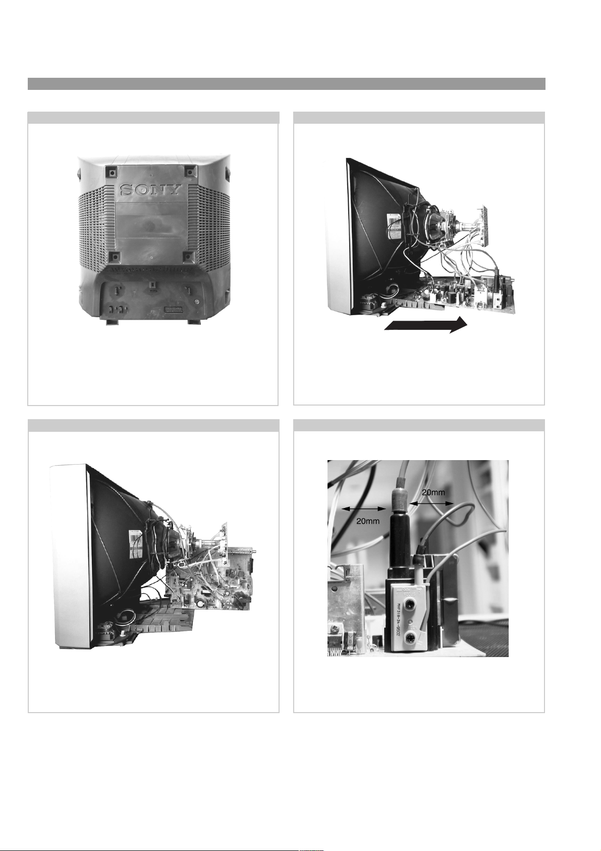
KV-21FT2
2-7. Rear Cover Removal
=>
=>
=>
=>
Remove the rear cover fixing screws indicated. Pull the rear
cover straight back until clear of chassis.
2-8. Chassis Removal and Refitting
=>
=>
=>
To remove the chassis release the clips indicated at opposite
sides of the main bracket and slide the chassis away from the
beznet. Ensure that the interconnecting leads are released from
their purse locks to prevent damage being caused.
2-9. Service Position
Position the A board as shown to gain access to its solder side.
Take care not to trap the interconnecting leads in the process.
2-10. Wire Dressing
Ensure that all wires do not touch heat-sinks and high temperature hot spots. All wires must be kept at a minimum distance of
20mm away from the EHT lead.
14
 Loading...