

Page 1

KV -2199XDK
RM-952
SELF DIAGNOSTIC FUNCTION
The units in this manual contain a self-diagnostic function. If an error occurs, the STANDBY/TIMER lamp will automatically
begin to flash.
The number of times the lamp flashes translates to a probable source of the problem. A definition of the STANDBY/TIMER
lamp flash indicators is listed in the instruction manual for the user’s knowledge and reference. If an error symptom cannot
be reproduced, the remote commander can be used to review the failure occurrence data stored in memory to reveal past
problems and how often these problems occur.
1. DIAGNOSTIC TEST INDICAT ORS
When an errors occurs, the STANDBY/TIMER lamp will flash a set number of times to indicate the possible cause of the
problem. If there is more than one error, the lamp will identify the first of the problem areas.
Result for all of the following diagnostic items are displayed on screen. No error has occured if the screen displays a “0”.
Diagnostic
Item
Description
• Power does not
turn on
• +B overcurrent
(OCP) or
overvoltage
(OVP)
• Vertical deflection
stopped
• Horizontal
deflection
overdrive
• White balance
failure (no
PICTURE)
• Micro reset
No. of times
STANDBY/TIMER
lamp flashes
Does not light
2 times
5 times
—
Self-diagnostic
display/Diagnostic
result
—
002:000 or
002:001~255
003:001~255
004:001~255
at the same time
005:000 or
005:001~225
101:00 or
101:001~225
Probable
Cause
Location
• Power cord is not plugged
in.
• Fuse is burned out F4601
(F)
• H.OUT Q511 is shorted. (A
board)
• IC701 is shorted. (C3 board)
• -13V is not supplied. (A
board)
• IC 503 faulty (A board)
• G2 is improperly adjusted.
(Note 2)
• CRT problem.
• Video OUT IC701 is faulty.
(C3 board)
• IC301 is faulty. (A board)
• No connection A board to
C3 board.
• Discharge CRT (C3 Board)
• Static discharge
• External noise
Detected
Symptoms
• Power does not come on.
• No power is supplied to the
TV.
• AC power supply is faulty.
• Power does not come on.
• Load on power line is
shorted.
• Has entered standby state
after horizontal raster.
• Vertical deflection pulse is
stopped.
• Power line is shorted or
power supply is stopped.
• No raster is generated.
• CRT cathode current
detection reference pulse
output is small.
• Power is shut down shortly,
after this return back to
normal.
• Detect Micro latch up.
Note 1: If a + B overcurrent is detected, stoppage of the vertical deflection is detected simultaneously.
The symptom that is diagnosed first by the microcontroller is displayed on the screen.
Note 2: Refer to screen (G2) Adjustment in section 3-4 of this manual.
– 4 –
Page 2
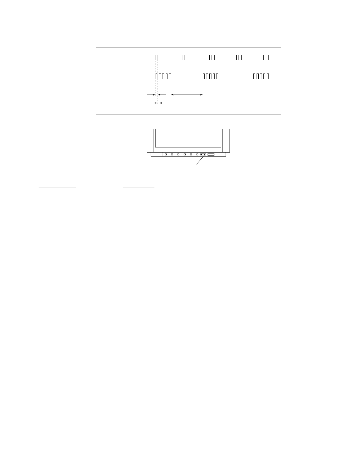
2. DISPLA Y OF STANDBY/TIMER LIGHT FLASH COUNT
2 times
5 times
KV-2199XDK
RM-952
Lamp ON 0.3 sec.
Lamp OFF 0.3 sec.
Lamp OFF 3 sec.
STANDBY/SLEEP lamp
Diagnostic Item Flash Count*
+B overcurrent/overvoltage 2 times
Vertical deflection stopped
White balance failure 5 times
* One flash count is not used for self-diagnostic.
3. STOPPING THE STANDBY/TIMER FLASH
Turn off the power switch on the TV main unit or unplug the power cord from the outlet to stop the STANDBY/TIMER lamp
from flashing.
– 5 –
Page 3
KV -2199XDK
RM-952
4. SELF-DIAGNOSTIC SCREEN DISPLAY
For errors with symptoms such as “power sometimes shuts off” or “screen sometimes goes out” that cannot be confirmed, it
is possible to bring up past occurances of failure for confirmation on the screen:
[To Bring Up Screen Test]
In standby mode, press buttons on the remote commander sequentially in rapid succession as shown below:
[Screendisplay] / channel [5] / Sound volume [-] / Power ON
˘
Note that this differs from entering the service mode (mode volume [+]).
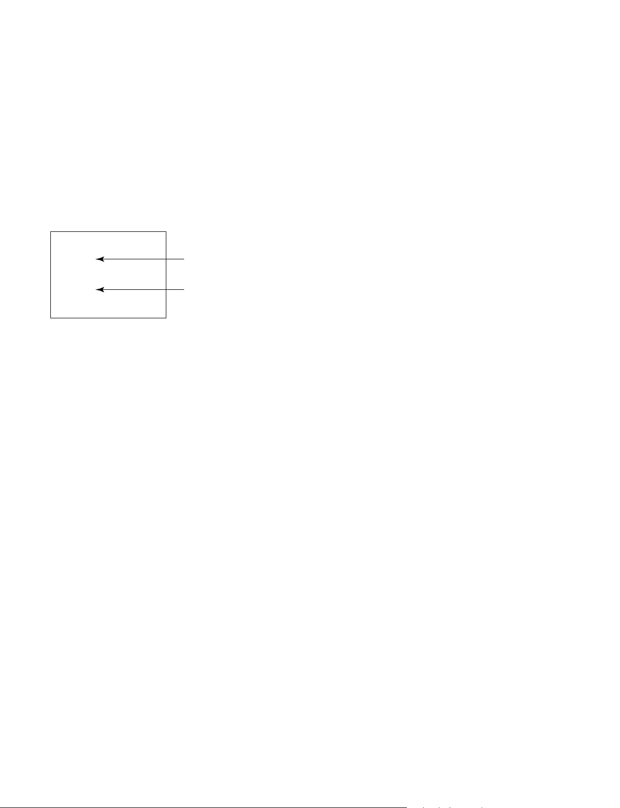
Self-Diagnosis screen display
SELF DIAGNOSTIC
002 : 000
003 : 000
004 : 000
005 : 001
101 : 000
Numeral "0" means that no fault has been detected.
Numeral "1" means a fault has been detected.
5. HANDLING OF SELF-DIAGNOSTIC SCREEN DISPLAY
Since the diagnostic results displayed on the screen are not automatically cleared, always check the self-diagnostic screen
during repairs. When you have completed the repairs, clear the result display to “0”.
Unless the result display is cleared to “0”, the self-diagnostic function will not be able to detect subsequent faults after
completion of the repairs.
[Clearing the result display]
To clear the result display to “0”, press buttons on the remote commander sequentially as shown below when the diagnostic
screen is being displayed.
Channel [8] / 0
[Quitting Self-diagnostic screen]
To quit the entire self-diagnostic screen, turn off the power switch on the remote commander or the main unit.
– 6 –
Page 4
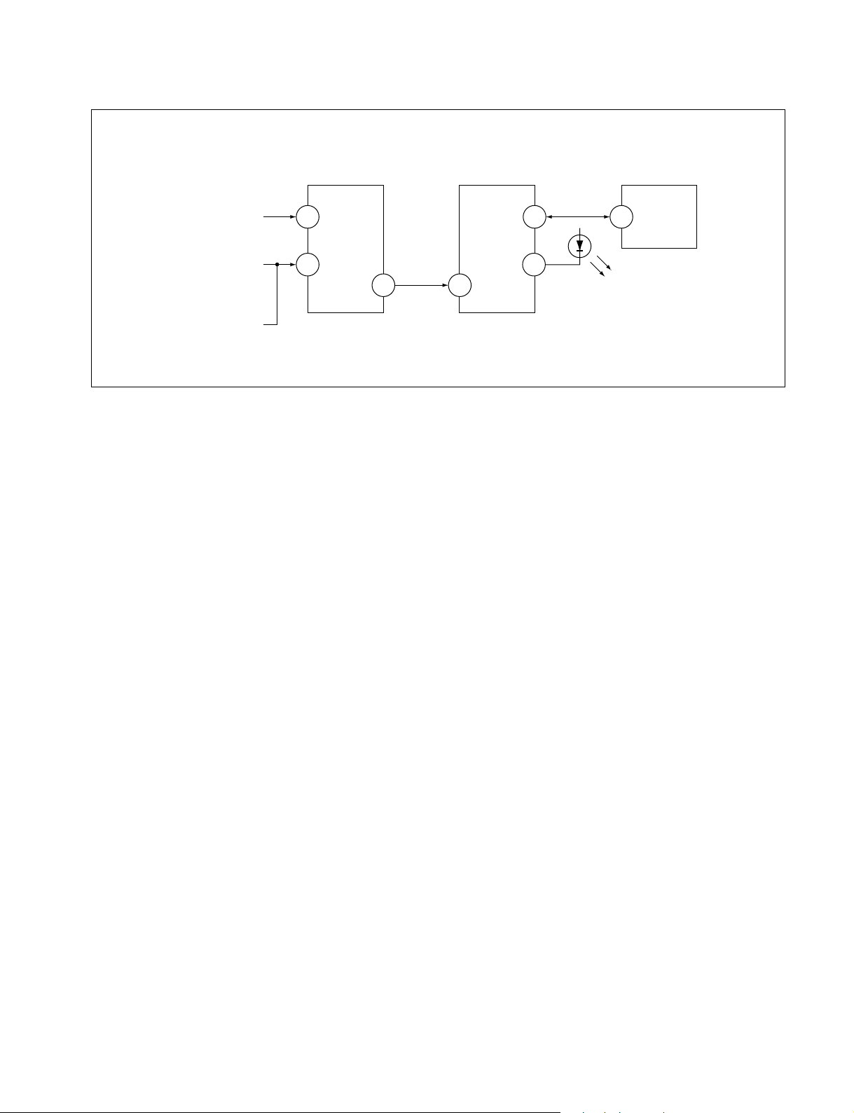
6. SELF-DIAGNOSTIC CIRCUIT
KV-2199XDK
RM-952
FROM
CRT
FROM
[+B] Q604 C
[V] Q509/507
IC301
Y/CHROMA JUNGLE
IK-IN
MP/
18 51
PROTECT
SDA
4635
IC001
SYSTEM
IO-8DAT
O-LED
IO-SDAT
MEMORY
B-DAT
54521
IC003
[+BovercurrentªOCPº] Occurs when an overcurrent on the +B(135) line is detected by Q604. If Q604 go to ON
and the voltage to pin 18 of IC301 should go down when V.SYNC is more than seven
verticals in a period, the unit will automatically turn off.
[Verticaldeflectionstopped] Occurs when an absence of the vertical deflection pulse is detected by Q509 and IC001
shut down the power supply.
[Verticaldeflectionovercurrent] Occurs when an overcurrent on V drive line is detected by Q507. Power supply will be
shut down when detect this by IC001.
[Whitebalancefailure] If the RGB levels* do not balance or become low level within 5 seconds, this error will be
detected by IC301. TV will stay on, but there will be no picture.
* (Refers to the RGB levels of the AKB detection Ref pulse that detects IK.)
– 7 –
Page 5

KV-XG29M85
RM-952
SECTION 4
CIRCUIT ADJUSTMENTS
4-1. ADJUSTMENTS WITH COMMANDER
Service adjustments to this model can be performed using the
supplied Remote Commander RM-952.
a. ENTERING SERVICE MODE
With the unit on standby
n
[DISPLAY] n 5 n
VOL (+) n [POWER]
This operation sequence puts the unit into service mode.
The screen display is :
Device
Name
GEO
Suffix No
(OEM Code)
Software version
b. METHOD OF CANCELLATION FROM SERVICE
MODE
Set the standby condition (Press [POWER] button on the
commander), then press [POWER] button again, hereupon it becomes TV mode.
c. METHOD OF WRITE INTO MEMORY
1) Set to Service Mode.
2) Press [1] (UP) and [4] (DOWN), to select the adjustment.
4) Press [MUTING] button to indicate WRITE on the screen.
5) Press [0] button to write into memory.
d. MEMORY WRITE CONFIRMATION METHOD
1) After adjustment, pull out the plug from A C outlet, and then
plug into AC outlet again.
2) Turn the power switch ON and set to Service Mode.
3) Call the adjusted items again to confirm adjustments were
made.
Item
Name
Item No
00
1.0C
Data
HPS 1C SERVICE
59 7F 000A0626S
Total Power-On time (hours)
Marking of new NVM
Mode
p
PAL,SECAM:50
NTSC :60
50
4-2. ADJUSTMENT METHOD
Item Number 00 of device GEO
This explanation uses H-Position as an example.
1. Select “GEO 00 HPS” with the 1 and 4 buttons.
2. Raise/lower the data with the 3 and 6 buttons.
3. Select the optimum state. (The standard is 1F for PAL
reception.)
4. Write with the
WRITE.)
5. Execute the writing with the - button. (The WRITE
display will be changed to red color while excuting, and
back to SERVICE.)
Example on screen display :-
GEO 00
626S 1.0C
GEO 00
626S 1.0C
GEO 00
Write executed with [0]
Use the same method for all Items. Use 1 and 4 to select the
adjustment item, use 3 and 6 to adjust, write with [MUTING],
then execute the write with -.
Note : 1. In [WRITE], the data for all items are written into
2. For adjustment items that have different standard
[MUTING] button. (The display changes to
1F SERVICE 50HPS
7F 0 000A59
1F WRITE 50HPS
7F 0 000A59
Write with [MUTING]
1F SERVICE 50HPS
7F 0 000A59626S 1.0C
memory together.
data between 50Hz or 60Hz, be sure to use the
respective input signal after adjustment.
GREEN
Adjusted with [3]
and [6] buttons.
GREEN
RED
The WRITE display
then the display
returns to green
SERVICE
1, 4 Select the adjustment item.
↓
3, 6 Raise/lower the data value.
↓
[MUTING] Writes.
↓
- Executes the writing.
7, - All the data becomes the values in memory.
8, - All user control goes to the standard state.
5, - Service data initialization (Be sure not to use
usually.)
2, - Copy and write all data.
[MUTE], - Write 50Hz adjustment data to 60Hz, or vice
versa.
– 28 –
Page 6

5-1. BLOCK DIAGRAM
SECTION 5
DIAGRAM
KV -2199XDK
RM-952
KV -2199XDK
RM-952
KV -2199XDK
RM-952
MAIN. TUVIF
TU101
BTF-LG433(I)
<slave: C0H>
JACK BLOCK
J401 4P
VIDEO IN 1
V1 V in
V1 L in
TV V in
TV L in
TV R in
AUDIO
PROSESSOR
IC203
TDA7429S
<slave: 80H>
TV V in
V1 V in
43
12
YC JUNGLE
IC301
CXA2130S
<slave:88H>
R out
22
G out
23
B out
24
IK in
21
H. DRIVE
19
H. PULSE
18
AUDIO OUT
IC201
TA8223K
RED OUT
GREEN OUT
BLUE OUT
C3
H-DRIVE
Q506
2SD774
HDT
T501
STV5112
Q704-712
H-OUT
Q511
2SC4927
CRT SOCKET
R out
G out
B out
SP ASSY
VM1
NECK ASSY
VM DRIVE
Q5902/5906
DY
Y21RSA-S
CRT
A51LPT70X
FBT
T503
NX-1748
J902 2P
VIDEO IN 2
(FRONT)
MONITOR
OUT
V2 V in V2 V in
V2 L in
L out 2
PIN-CONT
11
E/W
IC502
NJM2903M
4
32 31 30 37 39 40 15 28 29 30 31
V out
U out
Y out
V in
U in
Y in
VM out
R G B BLK
13
14
VD+
VD-
PIN-OUT
Q505
IRF614
5V REG & RESET
IC002 MM1319AF
PMC
L509
V-OUT
IC503
TDA8172
HLC
L510
STB TRANS
T604
STB SW TR
Q605
2SK2845
Additional
Color Matrix
SYSTEM
Ucom
IC001
CXP86449
SIRCS
I2L
RECEIVER
SBX1981-51P
IC901
MEMORY
IC003
M24C08-BN6
Audio Front Vcc
*+audio 3D Vcc
*-audio 3D Vcc
*
Not for this
model
+B
+9V
+5V
9V REC IC603
5V REC IC604
11V
7V
SRT
T603
POWER IC
IC601
STR-F6654
DGC
THP
THP600
LINE FILTER
T601
AC CORD
LINE
FILTER
T4601
F
– 36 – – 37 –– 35 –
Page 7

KV -2199XDK
RM-952
KV -2199XDK
RM-952
KV -2199XDK
RM-952
5-2. FRAME SCHEMATIC DIAGRAM 5-3. CIRCUIT BOARDS LOCATION
C3
PICTURE
TUBE
AC IN
CN4601
1
F
(CISPR)
CRT
CN704
1E
C3
(RGB OUT)
CN702
CN701
1 G2 FBT
1
2
CN703
1
2G
3
4
5
6
200V
H13
R
GND
IK
9V
E
B
VM
GND
9V
VM MUTE
GND
NC
+B
CN5901
1
2
3
4
5
6
7
MODULATION
VM1
VELOCITY
VM1
F
DGC
B
R
G
IK
9V
AC IN
GND
200V
GND
H1
DGCNCDGC
V-
H-
H-
H+
V+
H+
DY ASSY
CN305
2
1
65432
CN505
123
CN604
123
DY1
12345
6
(POWER SUPPLY, HV, MICON, Y/C JUNGLE)
NECK ASSY
A
CN306
VM
GND
123
9V
+B
NC
GND
VM MUTE4
6
5
7
A
1
CN4602
AC OUT
2
AC OUT
1GND
CN4603
2
1
CN104
GND 1
– 38 – – 40 –
CN601
AC IN
AC IN
– 39 –
Page 8

KV -2199XDK
RM-952
A BOARD WAVEFORMS
1 2 344
PAL SECAM
4.5Vp-p (V) 3.8Vp-p (V)
4 4 5 56
1.2Vp-p (H)
PAL
77778
1.1Vp-p (H)
SECAM
11
NTSC 4.43
13 14 15
NTSC 4.43NTSC 3.58
0.8Vp-p (H)
SECAM
1.0Vp-p (H)
NTSC
0.8Vp-p (H)
PAL/NTSC 3.58
12 12 12 13
3.0Vp-p (H)3.1Vp-p (H)
PAL/NTSC 3.58 SECAM/NTSC 4.43
0.9Vp-p (V)PAL :
NTSC 3.58 : 1.0Vp-p (V)
0.7Vp-p (H) 1.2Vp-p (H) 1.1Vp-p (H)
920Vp-p125Vp-p0.9Vp-p (H)
0.6Vp-p (V)
NTSC 3.58 NTSC 4.43 PAL
SECAM NTSC 4.43 PAL/SECAM/NTSC 3.58
1.1Vp-p (H)3.7Vp-p (V)
10988
PAL : 2.7Vp-p (H)
NTSC :
2.8Vp-p (H)1.1Vp-p (H)
16
1.4Vp-p (V)
1.3Vp-p (H)
0.8Vp-p (H)
10
SECAMPAL/NTSC
0.8Vp-p (H)0.8Vp-p (H)
1.0Vp-p (H)3.1Vp-p (H)3.0Vp-p (H)
– 42 –
Page 9

(1) Schematic Diagram of A1/2 board
1 2 3 4 5 6
7 8 9
10 11 12
13 14 15 16 17 18
19 20 21 22 23 24
25
2627282930
31323334353637
383940414243
4445464748
1 2 3
4 5 6 7 8 9
10
11 12 13 14 15 16
17 18 19 20 21 22 23
24 25 26
2728293031
323334353637
38394041424344
4546474849
505152
1
2
3
4
5
6
7
8
9
1 2 3 4
56
78
1
2
3
4
3
1
2
9
V
3
0
V
5
V
S
C
L
S
D
A
A
S
R
F
A
G
C
V
IF
9
V
A
F
T
O
U
T
G
N
D
R
O
U
T
L
O
U
T
N
C
N
C
N
C
N
C
N
C
5
V
D
E
T
O
U
T
P
L
L
-
S
W
N
C
N
C
N
C
S
C
L
S
D
A
N
C
1
1234
5 6 7
1
2
3
4
5
6
7
8
1
2
3
4
5
6
7
8
1
2
3
4
5
6
7
V
L
R
1
2
3
4
5
6
7
1
2
3
4
5
6
7
1
2
3
4
5
6
7
8
9
1
0
1
1
1234
56789
1011121314
15
1
2
3
4
1
2
1 2 3
1
2
3
1
2
3
1
2
3
4
1
2
3
1
123
456789
101112131415
161718192021
22 23 24 25 26 27
28 29 30 31 32
33 34 35 36 37 38 39
40 41 42
1 2 3 4
567
8
1
2
3
4
5
6
1
2
4
5
3
1
2
3
4
5
6
7
8
9
1
0
1
2
3
1
2
3
4
5
6
7
8
9
1
0
1
2
3
4
5
6
7
1
2
3
1
2
3
4
5
6
C029
C025
C026
C031
C030
C005
C004
C002
C014
C021
JR402
C332
R354
R355 C325
R361
R365
R364
R225
R226
R227
R015
R
3
1
0
R
30
9
C309
C304
D302
C315
C110
C109
C111
R111
C107
C105
R105
R109
R110
C103
R104
C033
C334
R366
R367
C335
C237
C336
R046
R
0
4
4
R
03
5
R031
R048
R
0
1
8
R008
R303
C
3
2
0
C
3
1
9
C305
C113
C114
R349
C009
R371
R372
R374
R
3
19
R348
L104
L105
L905
R376
C337
R021
L102
C301
L101
R420C411
R421
C410
R322
C340
C
0
1
3
R302
R053
R062
L003
C017
L004
R
3
0
8
C
3
1
3
JW122
JW123
JR104
JR110
R340
C308
JR203
R343
C333
R341
R336
R337
R342
R344
R424
C414
R425
C413
R423
C412
R422
R224
C258 C261
R223 C262
R362
C034
C006
C339
R
3
59
CN905
C400
R400
C
0
2
0
D300
CN305
R056
Q310
D407
D408
D409
R
0
4
2
R
0
0
1
R
1
1
2
C328
R390
R330
C
0
4
5
C257
R332
L301
L302
C326
X
3
03
D
3
1
7
J
R
1
0
1
R
1
03
C306
R357
C
0
2
4
C023
C
0
2
2
L
1
0
3
C222
R327
R
0
41
C
0
0
1
R
0
1
0
R
0
1
1
R
0
1
2
J
R
0
0
1
C
0
27
R370
C
33
0
R358
C
0
4
6
R910
R055
R377
R050
L001
C
0
1
1
R
3
04
C322
C302
JW017
L
0
0
5
R
0
4
0
R
0
4
5
R047
R
32
0
JR302
Q
3
0
9
R
0
2
9
R030
CN104
IC204
R335
R909
C338
R
3
69
C263
JW064
R066
C047
C327
C311
J
R
3
0
7
R
31
8
R363
C
3
24
J
R
20
5
C
34
5
C
3
41
C
91
2
C
0
1
5
L
0
0
2
C317
CN001
C041
C
0
4
2
C
0
4
3
C044
R356
C
0
1
2
C
0
1
6
C115
C116
C117
C211
C
2
1
2
C215
C216
C218
C220
C223
C227
C228
C229
C230
C231
C
2
32
C
2
33
C
2
3
4
C
23
5
C
23
6
C238
C240
C241
C242
C
2
4
3
C244
C
245
C248
C249
C251
C
2
52
C253
C246
C
2
5
4
C255
C256
C259
C265
C
3
0
0
C303
C
3
1
4
C329
C342
C901
C905
C906
C907
C910
C911
C914
CN101
CN102
CN103
CN105
CN106
CN201
CN202
CN203
CN204
CN302
CN303
CN608
CN904
D
0
0
2
D003
D
0
0
4
D203
D303
D304
D305
D310
D314
R321
D906
FB101
FB102
C260
JW104
JR202
JR404JR405
JW075
JW080
JW100
JW111
J
W
1
12
JW301
JW302
JW901
JW902
L204
L901
PS200
Q001
Q002
D311
D312
D313
D
0
0
1
Q313
R360
Q204
Q301
Q304
R
316
Q307
Q308
Q311
Q312
Q404
R017
R022
R023
R
0
24
R
0
2
5
R
0
2
6
R
0
2
7
R
03
8
R039
R052
D
0
0
5
R
0
54
R061
R063
R064
R065
R113
R213
R214
R215
R216
R217
R218
R
2
1
9
R220
R221
R229
R331
R231
R234
R235
R236
R237
R305
R306
R311
R312
R313
R314
R315
R317
R328
R329
R333
R334
R
3
3
8
R339
R345
R350
R351
R368
R373
R
3
78
R404
R405
R406
R901
R903
R904
R905
R906
R911
R912
R913
R914
R915
R916
R917
R918
S901
S902
S903
S904
S905
S906
S907
R411
JR105
JW008
R426 R419
R418R417
R414
R413
R412
R408
C407
CN304
C409
C408
C405
C404
C402
Q201
R049
R107
R108
C
318
JR304
R019
R002
R036
C224
X301
C053
C055
C048
C050
C051
C008
CN308
CN107
R346
R347
D100
IC100
JR107
R
0
2
8
R101
R102
JR109
C225
C
2
50
C
2
4
7
C401
C403
C406
C415
C908
C909
J401
J901
J902
JR401
JR403
R222
R401
R402
R403
R407
R409
R410
R415
R416
R907
R908
Q315
C310
CN205
D319
R057
R307
JR020
C054
R
0
3
4
C
2
1
0
R013
D006
R014
C
0
1
0
R
0
3
2
X
0
0
1
C032
C028
D901
D902
D904
D905
D401
D404
R043
D309
C003
R004
R005
C312
IC
0
0
2
Q003
Q004
IC901
Q901
Q902
IC003
Q203
Q207
Q206
Q303
Q302
Q
30
5
Q
3
06
Q101
Q401
D403
D405
D402
D406
D315
D316
D301
D306
D307
D308
IC301
CP301
IC203
R037
R006
R007
R
0
0
9
C221
IC201
JW202
C226
R202
JW205
C323
JW201
C101
C106
R
11
6
J
R
1
0
2
R
1
15
R
1
14
R106
C007
C019
C108
C112
C202
C203
C208
C217
C331
CN306
CN307
CN901
FB103
L902
Q202
R003
R
0
1
6
R067
R203
R204
R210
R211
R212
R228
R230
R326
R902
C206
C205
C209
C307
X302
CN301
IC001
Q205
R208
R301
Q402
Q403
TU101
C104
C316
C219
C213
C214
JW203
C207
R209
C264
R205
R206
R207
C902
JW006
D903
C204
JW204
C913
D
3
2
0
R375
D
3
2
1
22
220p
B:CHIP
220p
B:CHIP
47
4.7
2.2k
:CHIP
2.2k
:CHIP
1
10k
:CHIP
220
:CHIP
0
:CHIP
220
:CHIP
220 :CHIP
220
:CHIP
100
:CHIP
100
:C
H
IP
1
0
0
:C
H
IP
47
470p
B:CHIP
470p
B:CHIP
470p
B:CHIP
100
:CHIP
470p
B:CHIP
0
:CHIP
470
:CHIP
10k
:CHIP
10k
:CHIP
1k
:CHIP
1
0
0
:C
H
IP
1
0
0
:C
H
IP
1k :CHIP
10k
:CHIP
2
2
0
:C
H
IP
4.7k
:CHIP
1k
:CHIP
0
.01
F
:C
H
IP
0.01
F
:C
H
IP
47
47
10k
:CHIP
0.22
10
0
:C
H
IP
10k
:RN-CP
10k
:CHIP
470
16V
#
#
#
#
#
#
#
#
#
#
#
#
#
#
#
#
2.2
22k
:CHIP
##
#
#
220
:CHIP
0.0
1
B
:C
H
IP
0
:CHIP
1k
:CHIP
470
:CHIP
68p
CH:CHIP
JW(5mm)
1
0
0
:C
H
IP
1
1
6V
F
:C
H
IP
#
#
#
#
#
100
:CHIP
220p
CH:CHIP
#
#
#
#
#
#
#
#
#
#
#
#
#
#
#
#
##
##
12k
:CHIP
0.01
F:CHIP
0.1
25V
B:CHIP
0.1
25V
B:CHIP
0.1
25V
B:CHIP
0.1
25V
B:CHIP
0.1
25V
B:CHIP
0.1
25V
B:CHIP
0.1
25V
B:CHIP
0.1
25V
B:CHIP
#
2
2
0
:C
H
IP
#
#
#
#
0 :CHIP
6P
WHT
:S-MICRO
10k
:CHIP
#
#
#
#
0
:C
H
IP
:C
H
IP
1
00
:C
H
IP
0.1
25V
B:CHIP
#
#
#
#
220
:CHIP
#
#
#
#
#
18p
CH:CHIP
18k
:CHIP
1
0
p
C
H
:C
H
IP
10p
CH:CHIP
1
0
p
C
H
:C
H
IP
#
1
00
:C
H
IP
#
4
.
7
k
:C
H
IP
4
.
7
k
:C
H
IP
4
.7
k
:C
H
IP
#
0
.
1
2
5V
B
:C
H
IP
220
:CHIP
0
.1
2
5
V
B
:C
H
IP
1k :CHIP
#
4.7k :CHIP
10k :CHIP
1M
:CHIP
10k :CHIP
JW(5mm)
#
1
0k
:C
H
IP
470p
B:CHIP
470p
B:CHIP
#
:C
H
IP
1
0
0
:C
H
IP
:
C
H
IP
:CHIP
4.7k
:C
H
IP
#
#
1
k
:C
H
IP
#
1P
:TAB
#
680
:CHIP
4.7k :CHIP
4700p
B:CHIP
#
#
#
1k :CHIP
100p
CH:CHIP
22
10
#
1.2k
:C
H
IP
18k :CHIP
0
.0
0
4
7
B
:C
H
IP
#
#
0
.
22
2
5
V
B
:C
H
IP
0
.
1
2
5V
B
:C
H
IP
0
.0
0
1
B
:C
H
IP
#
0.1
25V
B:CHIP
100p CH:CHIP
1
0
0
p
C
H
:C
H
IP
1
00
p
C
H
:C
H
IP
100p
CH:CHIP
2.2k
:CHIP
68
p
C
H
:C
H
IP
#
#
#
470
25V
1
0
0
1
6
V
1000
25V
0.01
B:CHIP
0.15
:MPS
1000
25V
22
0.022
B:CHIP
0.018
B:CHIP
0.0056 B:CHIP
0.018
B:CHIP
0.0056
B:CHIP
0.
0
22
B
:C
H
IP
0
.1
2
5
V
B
:C
H
IP
0
.1
2
5
V
B
:C
H
IP
0
.1
2
5
V
B
:C
H
IP
0.1
25V
B
:C
H
IP
2.2
16V
F:CHIP
2.2
16V
F:CHIP
1
16V
F:CHIP
2.2
16V
F:CHIP
0
:C
H
IP
0.68
16V
F:CHIP
1
16
V
F
:
C
H
IP
0.0012
B:CHIP
0.1
25V
B:CHIP
0.0047
B:CHIP
1
1
6V
F
:C
H
IP
0.022
B:CHIP
0.0056
B:CHIP
2
2
0.022
B:CHIP
0.1
25V
B:CHIP
100
16V
2.2
16V
F:CHIP
#
10
#
0.01
:MPS
4.7
1
16V
F:CHIP
470p
CH:CHIP
47
47
470p
CH:CHIP
#
#
#
#
#
4P
WHT
3P
WHT
:S-MICRO
3P
BLK
:S-MICRO
#
#
#
#
#
#
#
DA204K
#
#
#
#
1SS355TE
10k
:CHIP
SPB-26MVWF
#
#
#
#
0
:CHIP
0
:CHIP
0
:CHIP
#
#
15MM
#
#
15MM
#
:EL0606
1.5A
#
2SC2712
1SS355TE
1SS355TE
1SS355TE
1
S
S
3
5
5
T
E
2SC2712
220
:CHIP
2SA1162
2SA1162
#
1.5
k
:C
H
IP
2SC2712
2SA1162
#
2SA1162
2SA1162
1k
:CHIP
220
:CHIP
#
2.
2
k
:C
H
IP
2
.2
k
:C
H
I
P
2
.
2
k
:C
H
IP
1
0
k
:C
H
IP
#
#
#
1
S
S
3
5
5
T
E
#
220 :CHIP
330
:CHIP
330
:CHIP
330
:CHIP
820
:CHIP
10k
:CHIP
10k
:CHIP
2.7k
:CHIP
2.7k
:CHIP
5.6k
:CHIP
5.6k
:CHIP
1
00
:C
H
IP
100
:CHIP
0:CHIP
10k
:CHIP
0
:CHIP
0
:CHIP
4.7
6.8k
:CHIP
6.8k
:CHIP
4.7
:CHIP
1.2k
:CHIP
10k
:CHIP
47
:CHIP
470
:CHIP
1.5k
:CHIP
680
:CHIP
#
15k
:CHIP
#
#
10k
:CHIP
2.2M
:CHIP
2
2
0
:C
H
IP
#
22k
:CHIP
3.3k
:CHIP
1.5k
:CHIP
#
#
10k
:CHIP
1k
:CHIP
10k
:CHIP
330
75
:CHIP
220
:CHIP
470k
:CHIP
15k
:CHIP
5.6k
:CHIP
470
:CHIP
1k
:CHIP
1.8k
:CHIP
3.3k
:CHIP
47
:CHIP
470
:CHIP
470
:CHIP
1
0
0
p
C
H
:C
H
IP
1
8
0
:C
H
IP
220p
CH:CHIP
#
470k
:CHIP
#
220
:CHIP
75
:CHIP
470k
:CHIP
15k
:CHIP
470k
:CHIP
68
:CHIP
470
:CHIP
1k
:CHIP
1
16V
F:CHIP
#
4.7
470p
CH:CHIP
470
16V
470p
B:CHIP
1
16V
F:CHIP
UN2216
LSP-MUTE
#
#
#
0
.01
F:C
H
IP
#
10k
:CHIP
100
:CHIP
100
:CHIP
470p
CH:CHIP
100p
CH:CHIP
100p
CH:CHIP
100p
CH:CHIP
100p
CH:CHIP
100p
CH:CHIP
100p
CH:CHIP
#
#
UN2213
4.7
#
#
#
#
1
0
0
1
6
V
4.7k
:CHIP
1SS355TE
100 :CHIP
10
0
p
C
H
:C
H
IP
#
8
M
H
z
0.47 16V B:CHIP
0.022
B:CHIP
UDZSTE-179.1B
PROTECT
UDZSTE-179.1B
PROTECT
UDZSTE-179.1B
PROTECT
UDZSTE-179.1B
PROTECT
1k
:CHIP
UDZSTE-175.1B
100 :CHIP
100
:CHIP
1
16V
F:CHIP
M
M
1
3
1
9
A
F
R
E
S
E
T
+
5
V
R
E
G
UN2111
SWITCH
UN2211
SWITCH
SBX1981-51
REMOTE SENSOR
IR-DET
UN2213
LED DRIVE
UN2213
LED DRIVE
M24C08-BN6
NVM
UN2213
VCC SWITCH
UN2213
MUTE
UN2213
MUTE
2SA1162
MATRIX
2SC2712
MATRIX
2S
A
1
16
2
S
W
2
S
A
11
62
S
W
2SC2712
BUFFER
UN2216
MUTE SW
UDZSTE-179.1B
PROTECT
UDZSTE-179.1B
PROTECT
UDZSTE-179.1B
PROTECT
UDZSTE-179.1B
PROTECT
1SS355TE
PROTECT
UDZS-TE17
PROTECT
1SS355TE
PROTECT
1SS355TE
PROTECT
1SS355TE PROTECT
1SS355TE PROTECT
CXA2130S
Y/C JUNGLE
#
FILTER BLOCK
COMB
TDA7429S
AUDIO SW
PROCESSOR
100
:CHIP
#
0
:CHIP
#
10
TA8248K
AUDIO AMP
5.0MM
1
10V
:CHIP
15k
:CHIP
5.0MM
#
5.0MM
#
#
#
#
#
#
#
#
#
#
100p
CH:CHIP
100p
CH:CHIP
#
#
#
#
#
#
#
#
#
#
#
#
#
4P
JACK
1-770-785-11
2P
JACK
#
#
0
:CHIP
#
#
#
#
#
#
#
#
#
#
#
#
#
#
#
#
#
#
#
#
#
4.43MHz
47
16V
47
25V
47
16V 47
16V
8200p
:CHIP
8200p
:CHIP
22
10
#
7P
:S-MICRO
#
4P
TO SPEAKER
#
UN2216
0
:CHIP
#
1k
3.9k
:CHIP
3.3k
:CHIP
56
#
56
:CHIP
4.7
6.8k
:CHIP
#
330
0.0033mF
B:CHIP
#
#
#
#
BTF-LG433
100
10V
47
25V
0.15
:MPS
100
16V
1000
25V
#
0.033
:PP
3.3k
:CHIP
2.2
F:CHIP
16V
3.3k :CHIP
3.9k
:CHIP
1.5k
:CHIP
0.01
:MPS
#
#
0.033
:CHIP
#
100
10V
U
D
Z
S
-T
E
1
7
#
:CHIP
U
D
Z
S
-T
E
1
7
H
D
S
T
-B
Y
N
S
M
U
T
E
N
S
R
O
T
H
P
A
F
C
V
D
-
V
D
+
E
W
A
B
L
7V
7
V
1
1
V
+
B
9V
5
V
9
V
30V
S
T
B
Y
7
V
9
V
.BLK09C3
A
U
D
+
V
C
C
A
U
D
I-
G
N
D
7
V
S
A
P
S
T
A
U
D
IO
S
W
L
S
D
A
S
C
L
R
C
V
/Y
R
G
B
Y
S
L
L
R
R
YSY
R
-Y
B
-
Y
R-Y
B
-Y
Y
Y
S
S
D
A
S
C
L
L
R
S
A
P
S
T
V
O
L
C
O
N
T
S
C
L
S
D
A
L
R
R
L
S
D
A
S
C
L
S
C
L
S
D
A
L
R
SDA
YS
R
L
S
IN
C
IN
C
IN
S
C
L
S
D
A
SDA
A
U
D
IO
S
W
C
V
/Y
1
R
L
L
R
C
V
/Y
1
R
R
Y
M
R
G
B
Y
S
R
G
B
Y
S
CV/Y
L
C
V
/Y
1
SCL
Y
M
S
IN
S
IN
L
SCL
*
*
*
*
CONTROLLER
*
MUTE
*
:CHIP
*
:CHIP
SP R
SP GND
SP GND
SP L
STBY+5V
GND
7V
LED2
LED1
GND
KEY2
KEY1
SIRCS
9V
C OUT
GND
Y OUT
VIDEO IN
Y OUT
5V
GND
C OUT
GND
VIDEO
NT/PAL
GND
B-INT
SDA
SCL
B
-Y
IN
R
-Y
IN
G
N
D
Y
IN
Y
S
IN
G
N
D
Y
O
U
T
G
N
D
R
-Y
O
U
T
B
-Y
O
U
T
7
V
G
N
D
3
0
V
G
N
D
A
F
T
2
S
C
P
V
T
IM
RED
GREEN
BLUE
BLK
GND
SDA
SCL
GND
VP
SCP
CVBS
G
N
D
G
N
D
1
1
V
S
D
A
S
C
L
G
N
D
S
IN
C
IN
C
V
/Y
IN
G
N
D
R
IN
L
IN
G
N
D
G
N
D
T
V
R
O
U
T
T
V
L
O
U
T
9V
ATT.SW
GND
VM
GND
9V
VM MUTE
+B
SIRCS
ST-BY
HSYNC
VSYNC
VSS
XTAL
EXTAL
KEY2
KEY1
VM MUTE
AFT1
AFT2
B.INT
NS MUTE
OSD/SYUU SW
AUDIO SW (F MONO)
T
E
X
T
LED1
LED2
NS ROT
(MODE) VOL
SCL1
SDA0
SDA1
W PROTECT
S
C
L
0
V
S
S
V
D
D
N
C
E
X
L
C
X
L
C
Y
M
Y
S
I
B
G
R
M
U
T
E
S
A
P
S
T
F
S
C
B
G
R
GND
IK
9V
TREBLE R
TREBLE L
AGND
SDA
SCL
DIG-GND
R-OUT
L-OUT
L-IN3
L-IN1
MONITOR-L
MONITOR-R
R-IN1
R-IN2
R-IN3
CREF
VS
L-IN2
AUXOUT-R
AUXOUT-L
MODEL R0
BASS-R1
BASS-R0
BASS-L1
BASS-L0
VAR-R
BASSO-L
VAR-L
REARIN
REAROUT
HP2
HP1
LP1
LP
PS1
PS2
PS3
PS4
R
E
S
E
T
O
U
T
G
N
D
R
E
F
I
N
XTAL2
XTAL3
(APCFIL)
VCC2
ABLFIL
Y2/CVBS2 IN
GND2
EB-YIN
ER-YIN
EYIN
YUVSW
SDAD
SCLD
VCC1
INT R2IN
INT G2IN
INT B2IN
INT BLK
EXT R1IN
EXT G1IN
EXT B1IN
EXT BKL
C1 IN
ABLIN
VTIM
COMBC IN
YCLAMP
COMBY IN
GND1EVIREF
VD+
VD-
VMOUT
REG
SSCP
HP/PROTECTHDAFCFIL
1KIN
ROUT
GOUT
BOUT
XTAL1APED
Y
1
/C
V
B
S
1
IN
M
O
N
O
U
T
T
V
/C
2
IN
T
V
O
U
T
G
N
D
R
S
T
G
N
D
NC
G
N
D
G
N
D
G
N
D
9
V
GND
N
C
AUDIO R
AUDIO L
VIDEO
AUDIO IN 2R
AUDIO IN 2L
AUDIO IN 1R
AUDIO IN 1L
VIDEO IN 1
VIDEO IN 2
(MONO)
(MONO)
(MONO)
OUT
MONITOR
G
N
D
9
V
M
U
T
E
R
O
U
T
L
O
U
T
GND
GND
I
N
T
P
R
O
T
N
T
/P
A
L
TO VM BOARD
A
U
D
G
N
D
A
U
D
G
N
D
A
U
D
+
V
C
C
A
U
D
+
V
C
C
M
O
D
E
L
R
1
G
N
D
R
IN
/G
N
D
N
F
2
/R
I
N
G
N
D
/
N
F
2
L
I
N
N
F
1
N
C
B
.S
.2
R
O
U
T
V
C
C
1
L
O
U
T
B
.S
.1
G
N
D
V
C
C
2
B
A
S
S
O
-R
R
IP
P
L
E
S
T
B
Y
-M
U
T
E
A
T
T
S
W
/M
O
M
U
T
E
M
O
D
E
L
L
1
M
O
D
E
L
L
0
7
V
A
P
C
N
A
P
C
N
G
N
D
G
N
D
C
V
/Y
IN
PH L
PH R
GND
V2
CN5901 CN703
TO B3 BOARD
CN6200
TO B3 BOARD
CN6206
TO B3 BOARD
CN1404
TO B3 BOARD
CN1406
TO H3 BOARD
CN3905
TO H3 BOARD
CN3603
TO B3 BOARD
CN1407
TO B3 BOARD
CN1405
R
E
S
E
T
5
V
G
N
D
G
N
D
L
IN
R
IN
L
-O
U
T
R
-O
U
T
G
N
D
M
U
T
E
N
C
F
M
O
N
O
M
O
D
E
S
A
P
IN
D
S
T IN
D
D
E
T
O
U
T
2
D
E
-E
M
P
N
C
A
F
T
IF
M
O
M
U
T
E
C
V
S
S
A
G
N
D
9
V
V
G
N
D
V
ID
E
O
1
V
ID
E
O
1
TO B6 BOARD
CN8403
TO B6 BOARD
CN8401
A
G
N
D
15.6
16.4
16.4
0
0
4.9
12.9
12.9
12.9
0
0
12.9
1
2
3
4
5
6
9
8
7
12
1110
13
MICON,Y/C JUNGLE
POWER SUPPLY,HV,
(
(
TO V1 BOARD
TO V1 BOARD
CN801
CN803
TO C3 BOARD
B-SSS10217-ME.-A..2199
5V
5V
5V
5V
5V
5V
5V
5V
5V
5V
5V
5V
30V
30V
30V
30V
30V
30V
30V
30V
30V
30V
30V
30V
9V
9V
9V
9V
9V
9V
9V
9V
9V
9V
9V
9V
9V
9V
9V
9V
9V
9V
9V
9V
9V
9V
30V
9V
9V
9V
9V
9V
5V
11V
11V
11V
11V
11V
11V
9V
9V
9V
9V
9V
9V
9V
9V
9V
9V
9V
9V
9V
9V
7V
5V
4
.9
4
.
8
1
.0
4
.9
0
4
.9
2
.6
(
2
.
2
)
2
.0
(2
.
7
)
1
.9
0
4
.
9
4
.9
(0
)
2
.
1
2
.2
0
4
.9
4
.8
0
.3
4
.8
3
.8
4
.
9
4
.
9
4
.9
(0
)
0
4
.8
0
0
4
.9
0
0
0
0
0
0
4
.9
2
.5
2
.
5
4
.8
4
.9
0
0
0
0
4
.9
4
.9
4
.6
4
.9
4
.
7
0
0
.1
0
0
3
.3
5
.1
1
.4
5
.1
4
.8
4
.3
0
.9
(0
)
4
.4
(4
.6
)
5
.1
0
3
.9
2
.3
3
.6
3
.5
5
.8
(3
.0
)
7
.7
1
.0
3
.5
3
.2
3
.9
3
.0
1
.6
1
.6
1
.6
0
4
.5
4
.5
4
.5
4
.1
(4
.9
)
4
.1
4
.1
4
.1
1
.7
4
.7
4
.8
4
.6
4
.0
5
.2
5
.1
0
5
.1
6
.0
5
.1
8
.7
0
(4
.3
)
0
0
0
4
.5
4
.5
4
.5
4
.5
4
.5
4
.5
4
.5
4
.5
4
.5
4
.5
4
.5
4
.5
4
.5
4
.5
4
.5
4
.5
4
.5
4
.5
4
.5
4
.
5
4
.5
4
.5
4
.5
4
.5
0
4
.6
4
.6
0
3
.9
3
.9
3
.9
3
.9
4
.5
4
.5
4
.5
4
.5
4
.5
4
.5
4
.5
4
.5
4
.5
8
.9
4.9
0
0
0
4.9 4.8+
4
.
8
0
0
7
.3
7
.
3
7
.3
0
0
0
4.8
4.8
4.9
0
0
0
4.9
0
4
.9
4
.9
4
.9
4
.
9
0000
1.1
1.1
0
0
1.2
0
0
8.9
15.7
1
.8
1
.6
1
6
.4
8
.3
8
.3
1
6
.1
0
1
6
.4
8
.4
0
.6
0
0
0
0
.6
0
0
0
0
0
0
0
0
0
8.5
4.6
8.1
8.8
4.8
8.1
4.2
0
0
4.8
4.1
0
4.1
2.2
2.8
8.9
0
5.2
4.5
4.8
0
5.2
A
(1/2)
123456789101112
A
B
C
13 14 15 16 17 18 19 20 21 22
D
E
F
G
H
I
J
– 44 – – 45 –– 43 –
Schematic diagram
A (2/2) board /
Schematic diagram
? A (1/2) board
Page 10

(2) Schematic Diagram of A2/2 board
HV
1
4
2
3
6
5
11
13
9
8
7
FV
SV
10
14
1
2
12345
1
2
3
1
2
3
4
5
6
1 2 3
4 5 6 7
1 2 3
4
567
8
1
3
4
7
8
9
10
1
2
1
2
3
4
5
6
1
2
3
4
1
2
1
2
3
4
1
1
23
4
-2
1
2
3
4
5
6
7
S
1
2
3
4
1
2
3
4
5
9
8
7
16
15
18
17
14
13
12
10
11
1
1
1
2
3
4
IO
G
IO
G
1
3 4
5
1
2
4
3
1
2
3
S
1
3
4
5
6 8
9
2
10
11
-2
1
2
3
4
C629
C635
L508
C565
C560
C527
R569
C540
R578
C558
C541
C566
C505
C557
C529
C555
R568
C516
L515
R507
SG501
C568
R597
C511
R524
C553
C552
Q506
C508
R556
R523
R538
R619
JW504
R559
L505
L506
JW503
L504
J
W
5
2
5
J
W
52
6
C548
C562
R640
R643
R649
C522
C547
C509
C524
R642
L503
C559
C647
C650
C652
R602
R609
R610
R611
R612
R616
C648
R657
C546
R528
R529
R535
R536
R540
R541
R545
R546
R547
R550
R520
C551
R614
C623
C549
R590
FB610
R644
JW604
JW605
C604
C536
C649
T604
R607
RY601
C641
C526
R608
R603
C636
R659
R660
R645
R651
R655
R527
RV500
C646
R599
R617
FB600
FB601
FB602
FB603
FB611
C514
FB501
R636
C506
FB502
R
5
21
C517
R560
L517
C501
R504
R503
C500
L516
R502
R549
R562
C519
R580
C530
R552
R646
R650
D
6
2
4
D632
D631
D638
D601
D633
IC503
C580
C581
D617
C583
D519
D527
D
5
2
8
IC603
CN601
C612
C611
C607
C608
R648
R653
R661
R530
R566
R522
FB615
JR500
JR501
C584
R516
R591
R593
R594
CN600
D513
R634
CN602
C654
C656
R681
C620
C651
D637
D620
D634 D635
D512
D511
D510
D508
D507
D505
R518
C564
R600
R534
D636
D622
D615
F600
CN606
CN604
R637
R635
FB613
C617
C
N
6
0
7
C642
FB616
S502
T501
R581
R533
R570
L518
L501
L514
R555
R574
C544
C534
R563
R572
R576
Q512
R586
R531
D533
T600
CN501
CN502
R551
R577
D612
C633
C644
C645
J
W
06
6
C503
C504
C507
C510
C513
C523
C528
C538
C539
C543
C554
C561
C563
C567
C570
C572
C585
C573
C574
C577
C582
C600
C601
C605
C606
C615
C616
C619
C621
C626
C627
C628
C632
C638
C639
C640
C655
C658
CN503
CN504
CN505
CN508
CN509
CN510
CN603
CN609
D509
D517
D522
D530
D
6
0
9
D613
D614
D611
D618
D621
D627
D
6
2
9
D
6
3
0
DY1
FB607
FB606
JR502
JW501
JW506
JW507
JW508
JW518
JW606
JW607
J
W
60
9
JW610
JW611
JW612
JW614
L502
L507
L510
L5
1
1
L
51
2
L513
L601
D628
D521
D531
D532
D602
D506
Q501
Q502
Q505
Q
6
0
5
Q608
R500
R501
R509
R508
R506
R510
R511
R515
R517
R519
R526
R532
R537
R539
R542
R543
R548
R553
R554
R558
R561
R564
R565
R567
R571
R573
R575
R579
R582
R583 R584
R585
R587
R588
R589
R592
R601
R613
R615
R620
R
6
39
R641
R647
R652
R654
R680
S501
T503
T504
T601
V
D
R
6
0
0
T505
R631
R630
R629
R628
R626
R625
R624
R623
R604
D607
D606
D604
D603
C657
C614
C610
C609
D504
D523
IC502
R632
D529
D525
D526
C571
C579
R514
R513
R512
R605
R618
R505
R525
R598 C576
D
6
2
3
C556
C533
C532
C518
D520
C537
C531
C643
C653
C634
C630
C512
C586
R595
Q511
R557
D625
JW615
R662
R627
Q601
Q602
Q603
D608
PH600
IC602
IC601
D605
Q607
Q604
Q503
T603
D518
IC604
Q606
Q507
Q509
S600
Q600
C603
R621
R656
D600
RY600
JW011
JW602
JW603
JW601
JW600
C502
C521
D616
FB605
C625
C631
JW608
R606
CN605
FB608
R596
THP600
C622
C624
L509
CN507
D534
R544
C602
C613
JW015
FB612
C618
D610
FB604
C550
R622
10
:LHL08
47
250V
470p
500V
B
330p
0.33
:MPS
33
160V
:HR
220p
500V
B
470
25V
1.5
:FPRD
10mH
:DCC
4.7
:FPRD
470p
500V
B
680
1/2W
:FPRD
680p
2kV
B
680p
2kV
B
4.7k
:RN
330
270k
1/2W
10k
:LHL08
:LHL08
:LHL08
470p
500V
B
680
3.3k
1k
100
16V
1.5k
47
1
2W
:RS
#
220k
1/2W
0.001
CH:CHIP
0.001
CH:CHIP
22
4.7
:FPRD
2.2k
:CHIP
10k
:CHIP
47k :CHIP
680
:CHIP
6.8
1/2W
:FPRD
100
10V
:LHL08
0.1
F:CHIP
1
100
25V
10k
:RN
22k
:RN-CP
220
:RN-CP
5.6k
:CHIP
5.6k
:CHIP
4.7k
:CHIP
4.7k
:CHIP
15k
:CHIP
15k
:CHIP
33k
:CHIP
100k
:CHIP
470
:CHIP
68k
:RN
7.5MM
7.5MM
1.5k
STB
0.1
:MPS
0.001
B:CHIP
330
25V
#
#
#
#
#
#
#
#
#
#
#
#
#
#
#
#
#
#
#
JW(5MM)
4.7k
0.0047
B:CHIP
DH5D1-0(M)
680p 500V B
0.1
:PT
22M
1/2W
470k
:RN
1k
:CHIP
10k
:CHIP
#
#
#
10 :CHIP
#
10
450V
4.7
22
0.047
B:CHIP
2SC3209-L
H-DRIVE
1.1UH
1.1UH
1.1UH
1.1UH
1.1UH
0.047
200V
:PT
1.1UH
15k
3W
:RS
33
160V
1.1UH
JW
(15
M
M
)
0.0033
B:CHIP
10k
:CHIP
#
#
#
#
#
#
#
18k
:RN
47
820p
500V
B
100k
:RN-CP
0.022
2.2k
:CHIP
15k 3W :RS
22
2W
:RS
M
A
1
1
1
-T
X
ERC04-06SE
ERC04-06SE
D1N20R-TR
#
ERA22-08TP3
TDA8172
V.OUT
#
#
#
#
#
GP08DPKG23
H-POSI
G
P
0
8
D
P
K
G
2
3
H
-P
O
S
I
L7809CV
2P
:VH
0.0047
500V
E
0.0047
500V
E
0.0047
500V
E
0.0047
500V
E
2.2k
:CHIP
4.7k
1W
:RS
4.7k
1W
:RS
JW(5MM)
#
10k
:RN-CP
1.1UH
0
:CHIP
0
:CHIP
#
22k
:CHIP
0.47
1/2W
:FPRD
0.47
1/2W
:FPRD
0.47
1/2W
:FPRD
#
GP08DPKG23
V.BOOST
8.2M
1W
2P
:MINI
#
#
#
470p
CH:CHIP
470p
CH:CHIP
RD6.8ES-T1B1
RD30ES-T1B1
MA111-TX MA111-TX
1SS355TE
1SS355TE
1SS355TE
1SS355TE
1SS355TE
1SS355TE
100
0.1 25V F:CHIP
56k
0.22 2W :RS
D1NS4-TA2
FMU-G26S
#
#
#
3P
:MINI
82k
3W
:RS
82k
3W
:RS
1.1UH
100p 1kV
#
2200
25V
JW(5MM)
SW
:LB
HDT
:HDT
4.7k
:CHIP
1k
6.8k
:CHIP
:EL0606
:LHL08
JW(5mm)#
#
#
#
#
#
#
#
#
3.3k
#
#
#
#
2.2k
220
3W
:RS
0.1
200V
:PT
0.01
250V
#
0.0022
1kV
R
#
#
0.0047
500V
E
330p
B
330p
CH:CHIP
680p
500V
B
0.0085
2kV
:PP
0.039
400V
:PP
#
0.0047
200V
:PT
0.0033
630V
:PP
#
0.82
250V
:PP
0.68
250V
:PP
#
#
0.033
200V
:PT
10
160V
0.15
200V
:PT
0.1
25V
B:CHIP
0.1
250V
#
330p
250V
330p
250V
#
0.022
400V
:PP
470p
250V
#
680p
500V
B
1000
25V
#
#
0.1
25V
B:CHIP
0.1
25V
B:CHIP
#
0.1
25V
B:CHIP
#
#
3P
:MINI
#
#
#
#
1P
10K
:CHIP
ERC06-15S
DAMPER
RGP10G
+15V.RECT
#
AU-01Z-WS
AU-01Z-WS
AU-01Z-WS
RN-4Z
#
31DQ06-FC5
#
#
6P
WHT
:DY
1.1UH
#
#
5MM
10MM
5MM
5MM
10MM
10MM
10MM
#
#
#
#
#
10mH
HLC
#
1
m
m
H
:LH
L0
8
1mmH
:LHL08
:LHL08
1SS119
RGP10G
-15V.RECT
1SS355TE
1SS355TE
1SS119
1SS119
#
#
IRF614 PIN-OUT
2
S
K
2
8
4
5
2SC2712
#
#
100
3W
:RS
68
3W
:RS
33k
:CHIP
68
2W
:RS
100
3W
:RS
#
#
#
4.7k
:RN-CP
#
22k
RN:CP
#
0
:CHIP
5.6k
:FPRD
#
33k
:RN
33k
:RN
2.2k
#
#
10k
:CHIP
220k
:CHIP
4.7k :RN
47k
:CHIP
#
100k
:CHIP
#
##
6.8
:FPRD
#
220
2W
:RS
220 2W :RS
#
1.2k
:FPRD
#
1.2
1W
:RS
470
3W
:RS
0
.
3
3
2
W
:R
S
0.27
2W
:RS
47
22k
2W
:RS
#
4.7
:CHIP
#
NX-1748
#
LFT
#
470p
2kV
B
470p
B
R
U
-1
P
#
#
47k
:CHIP
10k
:FPRD
470
1/2W
:FPRD
#
1k
:CHIP
#
47k
:CHIP
82k
:CHIP
100k
:CHIP
MA111
TF541M
RGP02-17PK
RD33ES-T1B
0.0022
500V
E
10
10
100
RGP10G
PIN-OUT
RGP10G
200V.RECT
NJM2903M-TE2
PIN-CONTROL
0.1
1/2W
:RF
#
#
#
#
#
#
#
#
#
#
120k
:CHIP
100k
:RN-CP
56k 0.1
:PT
U
D
Z
T
E
-1
7
1
5
B
470
25V
470
25V
470
25V
100
10V
#
220
2.2
:BP
100
10V
47
25V
100
16V
33
160V
0.033
25V
B:CHIP
0
:CHIP
#
2SD2578-CA
H-OUT
JW(7.5MM)
UDZSTE-1710B
#
#
6.8
10W
2SD2114K
SW
2SC2712
PROTECTION
UN2111
SWITCHING
RD20ESB2
SW
ON3171-R
PHOTO COUPLER
SE-135N
SENSOR AMP
STR-F6654
REG CONTROL
D4SB60L
A/C RECT
2SD2144S
RELAY DRIVE
2SA1091R
PROTECT
2SC2712
PROTECT
SRT
ERD29-08J
PIN DANPER
L7805CV
5V REG
2SC2712
SWITCHING
TRANSISTOR
2SA1162
PROTECT
2SC2712
V-PROTECT
SWITCH
PUSH BUTTON
#
#
#
#
#
#
5.0MM
10.0MM
10.0MM
#
#
0.0015
50V
CH:CHIP
220
16V
#
#
#
#
#
#
#
1.1UH
5.6k
3W
:RS
#
0
:CHIP
1.2
2W
:RS
0.1
:PP
330
450V
7.5MM
JW5MM
680p
1.5kV
11EQS04-NTAB
0UH
0.1
100V
:PT
33
3W
:RS
EW
AFC
HP
30V
+B
9V
5V
NS MUTE
NS ROT
VD-
VD+
HD
11V
ABL
1
1
V
7
V
ST-BY
STBY 7V
AUD+VCC
AUDI-GND
.BLK0426
.BLK0213
.BLK029C
.BLK029B
.BLK029A
.BLK042D
*
*
E-A3E-A3
+B
200V
C
ABL
H1
H2
-15V
E
DRV-IN
Vcc
F.B.-PLS
Vee
OUT-PUT
Vcc(OUT)
REF-VOLT
H+
H+
H-
H-
VV+
CN701
135V
GND
FBP
A
C
IN
A
C
IN
D
G
C
D
G
C
PFC
PFC
15V
VD+
GND
VD15V
NS ROT
NS MUTE
TO COATING EARTH
TO HV BLOCK
G
N
D
D
S
O
C
P
/F
B
N
C
D
G
C
C
H
K
D
G
C
C
H
K
GND7V11V
NS MUTE
E
V
IN
NC
3
D
-V
C
C
3
D
+
V
C
C
G
N
D
G
N
D
GND
15V
VD+
200V
GND
H1
TO D1 BOARD
GND
TO DGC
TO B3 BOARD
CN6205 TO DH BOARD
CN3802
CN1801
TO D1 BOARD
CN2823
CN2822
TO DY
DF
GND
TO F BOARD
CN4602
TO DGC
H.DY H.DY V.DY V.DY
POWER SUPPLY,HV,
MICON,Y/C JUNGLE
(
(
TO C3 BOARD
TO C3 BOARD
B-SSS10217-ME.-A..2199
15V
15V
15V
15V
15V
15V
15V
15V
15V
15V
135V
135V
135V
135V
135V
135V
135V
135V
135V
135V
135V
135V
15V
15V
15V
15V
15V
15V
200V
200V
200V
200V
9V
9V
9V
9V
9V
9V
9V
9V
9V
9V
9V
30V
30V
30V
30V
30V
9V
9V
9V
11V
11V
11V
11V
7V
7V
7V
7V
7V
7V
-2.3
0.2
0
17.1
*
*
0
0.5
127.1
119.9
135.4
0
119.8
2
.0
0
1
6
9
.8
1
7
.0
0
0.7
0
0
0
134.0
0
0
0
0.7
0
0
3.6
8.9
6.8
3.0 3.3
0
1.5
3.7
1.1
5.0
0
9.9
1
.1
1
3
.9
-1
3
.6
-1
3
.6
-1
2
.3
1
3
.7
1
.1
*
*
*
*
*
*
9.7
6.8
0
0
0
0.6
1.1
16
0
65.8
-0.9
14
13
17.1
3.9
3.7
13.4
13.7
123456789101112
A
B
13 14 15 16 17 18 19 20 21 22
C
D
D
E
F
G
H
I
– 47 –– 46 – – 48 –
Page 11

A BOARD IC001 CXP86461-622S
AN0~AN5 6
RMC
S1
SO
SCK
EC
TO
XLC
EXLC
R
G
B
I
YS
YM
HSYNC
VSYNC
HS0
HS1
A/D CONVERTER
6CH
REMOCON FIFO
SERIAL INTERFACE
UNIT
8-BIT TIMER/
COUNTER 0
8-BIT TIMER 1
ON SCREEN
DISPLAY
HSYNC COUNTER 0
HSYNC COUNTER 1
SS
INT0
INT1
INT2
INTERRUPT CONTROLLER
2
2
I2C BUS
INTERFACE UNIT
SCL0
SDA0
SDA1
SCL1
2
ADJ
SPC700 CPU CORE
ROM
12K/16K/24K/32K
40K/48K/60K BYTES
PRESCALER/
TIME-BASE TIMER
WATCHDOG TMER
32kHZ
TIMER/COUNTER
8-BIT PWM 8CH
8 (6)
PWM0~PWM7
(PWM0~PWM5)
TX
TEX
CLOCK GENERATOR
/SYSTEM CONTROL
352/704/1536 BYTES
(6CH)
XTAL
EXTAL
RST
RAM
14BIT PWM 1CH
VDDV
MP
PWM
NOTE:
The circuit indicated at left contains high voltage of over
600 Vp-p. Please pay attention when inspecting or
repairing it to prevent an electric shock.
8
PORT APORT BPORT CPORT DPORT EPORT FPORT G
8
6
2
8
2
2
3
8
5
PA0~PA7
PB0~PB7
PC0~PC5
PC6~PC7
PD0~PD7
PE0~PE1
PE2~PE3
PE4~PE6
PF0~PF7
PG3~PG6*, PG7
KV-2199XDK
RM-952
KV-2199XDK
RM-952
A BOARD
IC
IC001 B-10
IC002 C-9
IC003 A-9
IC100 B-5
IC201 B-11
IC203 C-3
IC204 B-2
IC301 B-6
IC502 E-6
IC503 J-5
IC601 I-8
IC602 H-6
IC603 D-8
IC604 D-10
IC901 I-13
PH600 H-7
TRANSISTOR
Q001 B-8
Q002 B-8
Q003 C-9
Q004 C-9
Q101 A-4
Q201 A-11
Q202 A-11
Q203 C-11
Q204 C-11
Q205 A-12
Q206 A-11
Q207 A-11
Q301 B-8
Q302 A-6
Q303 A-6
Q304 B-6
Q305 B-5
Q306 B-5
Q307 C-7
Q308 C-7
Q309 C-7
Q310 D-7
Q311 D-9
Q312 B-7
Q313 B-8
Q315 B-5
Q401 D-2
Q402 D-1
Q403 D-2
Q404 C-3
Q501 D-6
Q502 E-7
Q503 F-6
Q505 D-6
Q506 D-2
Q507 H-6
Q509 F-6
Q511 F-1
Q600 C-12
Q601 F-11
Q602 J-7
Q603 I-7
Q604 H-6
Q605 E-12
Q606 F-11
Q607 H-13
Q901 H-13
Q902 H-13
DIODE
D001 B-8
D002 C-8
D003 C-9
D004 D-8
D005 B-8
D006 A-3
D203 C-11
D300 A-9
D301 B-9
D302 B-6
D303 B-5
D304 B-5
D305 B-5
D306 C-5
D307 C-5
D308 B-5
D309 B-6
D310 A-6
D311 C-6
D312 C-6
D313 A-8
D315 B-7
D316 C-7
D317 B-9
D314 A-9
D319 C-6
D320 C-6
D321 B-6
D401 D-2
D402 C-3
D403 B-1
D404 C-2
D405 C-1
D406 B-1
D407 C-2
D408 C-1
D409 A-1
D504 D-5
D505 H-6
D506 F-6
D507 F-6
D508 I-5
D509 E-6
D510 F-5
D511 F-5
D512 G-5
D513 I-5
D517 F-2
D518 F-2
D519 F-2
D520 E-5
D521 I-4
D522 J-4
D525 F-5
D526 F-6
D527 F-3
D528 F-3
D529 F-5
D530 F-2
D531 E-6
D532 E-6
D533 D-2
D534 E-6
D600 G-13
D601 I-8
D602 G-13
D603 F-11
D604 J-7
D605 G-10
D606 E-11
D607 F-10
D608 E-11
D609 H-8
D610 J-8
D611 I-7
D612 F-8
D613 I-7
D614 H-7
D615 E-7
D616 E-9
D617 F-8
D618 F-9
D620 D-8
D621 F-8
D622 F-7
D623 F-12
D624 F-12
D625 D-12
D627 F-8
D628 G-5
D629 F-9
D630 E-9
D631 G-12
D632 F-12
D633 E-12
D634 F-11
D635 F-12
D636 D-12
D637 F-11
D638 E-11
D901 C-13
D902 D-13
D903 C-13
D904 D-13
D905 F-13
D906 I-13
KV -2199XDK
RM-952
– A Board –
– 50 – – 51 –– 49 –
Page 12

(3) Schematic Diagrams of C3 and VM1 boards
123456789101112
A
C3
FOCUS
FV
(RGB OUT)
B
H.STAT
C702
0.001
B
C
TO G2-FBT
CN705
D
D
1
#
C703
4.7
250V
Q706
2SC3271F-N
R AMP
8.9
C710
470p
R734
100
1/2W
R714
6.8k
3W
:RS
L706
JW(5mm)
150.0
8.4
D
T
9
5
0
-2
7
9
D
1
1
S
B
S
1
D703
1SS119-25TD
2SA1091
IK LIMIT
150.0
R724
:FPRD
R723
270k
:RN
C746
470p
1k
E
9V 9V
Q712
2SC2785
R DRIVE
F
9V
1.7
1.9
1.6
0
5
1
R
0
3
7
R
C714
680p
R733
R727
2.2k
B
120
G
9V
C716
100
16V
H
13 14 15 16 17 18 19 20 21 22
CN702
1P
:TAB
1
G2
1
200V
2
E
3
H1
CN701
3P
:MINI
TO A BOARD
CN505
1
GND
CN706
#
TO A BOARD
CN505
KG G2
KB
D
T
5
-2
9
1
1
S
S
1
H
CV KR G1 G4
D
T
5
CN704
-2
9
1
1
S
S
1
47
1
1
2
3
4
5
6
1P
:TAB
GND
CN703
6P
WHT
:S-MICRO
B IN
G IN
R IN
GND
IK
9V
TO A BOARD
CN305
TO A BOARD FBT
PICTURE TUBE
HV
A51LPT70X
C5900 R5927
##
JW5901
10MM
9VEVM MUTE
GND
VM
1
2
3
C
GND
N
4
5
6
C5901
#
L5901
R5928
#
C5903
0.0047
500V
E
CN5901
:S-MICRO
TO A BOARD
CN306
+B
7
C5902
330
16V
C5904
C5920
10
R5935
10k
0.5W
:RN-CP
Q5907
#
MUTE SW
D5901
1SS119-25TD
TEMP-CORR
R5903
47
1/2W
:FPRD
7P
#
R5934
12k
0.5W
:RN
R5901
220
0.5W
:RN
D5908
R5904
0.5W
C5919
8.7
C5921
68p
0.9
Q5908
2SC2785-HFE
BUFFER
JW5900
#
C5907
33
135.2
160V
R5908
1.5
:FPRD
#
L5902
3.2
R5932
R5906
1k
R5905
1k
Q5902
2SA1606-E
VM.DRIVE.1
135.0
C5908
0.047
200V
:PT
2SC2785-HFE
470
0.5W
:RN
R5911
68k
Q5909
BUFFER
8.7
C5906
0.047
:PT
2.6
R5933
0.5W
62.9
D5902
MTZJ-T-77- 39
DC.BIAS
C5910
0.001
9V
470
:RN
8.7
2.6
R5909 R5910
:PT
220
0.5W
:RN
C5912
0.1
200V
:PT
9
0
9
5
C
C5911
R5913
6
1
k
W
N
9
.5
.5
5
:R
1
0
R
R5915
0
0
1
:RN-CP
2SC2458TP-YGR
2.0
68
0.5W
:RN
R5919
1k
:FPRD
2.2
160V
D5905
1SS119
#
D5906
120
D5907
10k
120
0.5W
R5912
47k
D5903
0.5W
1SS119
:RN
Q5901
AMP
2.7
R5914
68
0.5W
:RN
2.0
R5921
150
:RS
D5904
MTZJ-T-77- 39
DC.BIAS
C5913
0.001
:PT
VM1
R5917
820
0.5W
:RN
5.6
R5918
R5929
10k
10
2W
0.5W
:RS
:RN-CP
4.3
C5915
#
Q5903
2SC2458TP-YGR
VM.DRIVE.2
0.1
0.2
AMP
C5914
100
16V
2SC4159
R5922
0.5W
2.7
C5918
120p
500V
B
62.9
3W
R5920
68k
C5916
0.047
:PT
2SC2458TP-YGR
0.3
5.0
5.0
2SA1175TP-HFE
0
BUFFER
Q5906
R5923
1.5
:FPRD
C5917
560
470
10V
:RN
Q5905
BUFFER
R5924
5MM
Q5904
R5925
47
:FPRD
(VELOCITY MODULATION)
QP QP VM
Q.P.-
Q.P.+
E
VM
CN5904
8P
1
QP-
2
QP-
3
QP+
4
QP+
5
E
6
E
7
VM
8
VM
3
QP-
2
NC
1
QP+
CN2801
#
R5930
470
0.5W
:RN
8.5
R5931
470
0.5W
:RN
#
330
:RN
R5902
560
:FPRD
R5907
C5905
1k
470
10V
B-SSS10217-ME.-VM1..2199
D
T
5
-2
9
1
1
S
S
1
R740
C704
0.022
400V
:PP
200V
200V
IK LIMIT
156.0
C712
680p
B
R731R732
150150
Q707
2SA1091
R719
300k
:RN
100
C717
47p
L701
:EL0607
C737
470p
R720
1k
:FPRD
R725
2.2k
B
R707
470
:RN
JW(5MM)
151.0
4.6
R755
1.2k
R706
680 :RN
1
0
7
D
R760
0
1
7
D
C706
16V
G2
0.7
4
3
R761
1.5
4.7
2SC2785
B DRIVER
B
R738
D713
D714
1SS119-25TD
C701
0.0047
2kV
E
R705
8.2
2W
:RS
R708
6.8
2W
:RS
R710
6.8k
3W
:RS
Q704
2SC2611
B AMP
152.2
JW(5MM)
8.7
C708
470p B
1SS119-25TD
Q710
1.5
R728
150
100
D711
8.3
R739
100
1SS119-25TD
8.2
7
0
7
D
1.2
D715
R703
100k
J701
SOCKET
154.0
8.4
8.4
C713
680p
KG
152.0
R713
1k
1/2W
B
1/2W
G2
31
G1-1
4
5
H1
H2
6
7
G1-2
KB
153.0
R711
1/2W
L712
:EL0606
C736
470p
D702
1SS119-25TD
Q708Q709
2SA1091
IK LIMIT
1.7
R722
1k
:FPRD
R721
680k
:RN
9V
R726
2.2k
D716
1SS119-25TD
9V
1SS119-25TD
1k
B
R756
1.2k
G4
RCV
13
RV702
110M
11
G1-3
1098
Q705
G AMP
8.9
D
T
8
5
0
-2
7
9
D
1
1
S
S
1
D
T
5
-2
9
1
1
S
S
1
Q711
2SC2785
G DRIVER
1.6
RD9.1ES-T1B
:EL0606
R712
6.8k
C709
470p
G
D717
149.0
3W
:RS
1.2
R729
KR
2
L711
B
150
1
R715
1k
1/2W
L710
:EL0606
200V
B
2SC3271F-N
R762
JW(5MM)
147.0
4.6
2
1
7
D
9V
R757
1.2k
I
B-SSS10217-ME.-C3.. 2199
– 53 –– 52 – – 54 –
Page 13

(4) Schematic Diagram of F board
123456 7
A
B
C
F (CISPR)
KV -2199XDK
RM-952
KV -2199XDK
RM-952
D
D
E
F
G
CN4601
2P
:VH
AC IN
AC IN
CN4603
1P
:TAB
TO A BOARD
CN104
GND
F4601
T3.15A
FUSE
250V
1
2
047
250V
C654
0.0
VDR461
ERZV14D621
C4602
0.47
250V
T4601
T.L.F
3
4
1
2
:PP
T4602
4
1
C4601
#
B-SSS10217-ME.-F..2199
R4601
1M
#
1/2W
3
2
1
AC OUT
2
AC OUT
TO A BOARD
CN4602
:VH
CN601
2P
H
I
– 57 –
– 58 –
 Loading...