

Sony KV-14FV1B-U Service Manual
SERVICE MANUAL
BC-5
CHASSIS
MODEL COMMANDER DEST. CHASSIS NO.
KV-14FV1B
KV-14FV1D
KV-14FV1E
KV-14FV1U
RM-C816 FR SCC-xxxx-A
RM-C814 AEP SCC-xxxx-A
RM-C814 ESP SCC-Q62B-A
RM-C815 UK SCC-xxxx-A
MODEL COMMANDER DEST. CHASSIS NO.
KV-21FV1B
KV-21FV1D
KV-21FV1E
KV-21FV1U
RM-C816 FR SCC-xxxx-A
RM-C814 AEP SCC-xxxx-A
RM-C814 ESP SCC-Q62A-A
RM-C815 UK SCC-xxxx-A
∗ Please file according to model size. ....
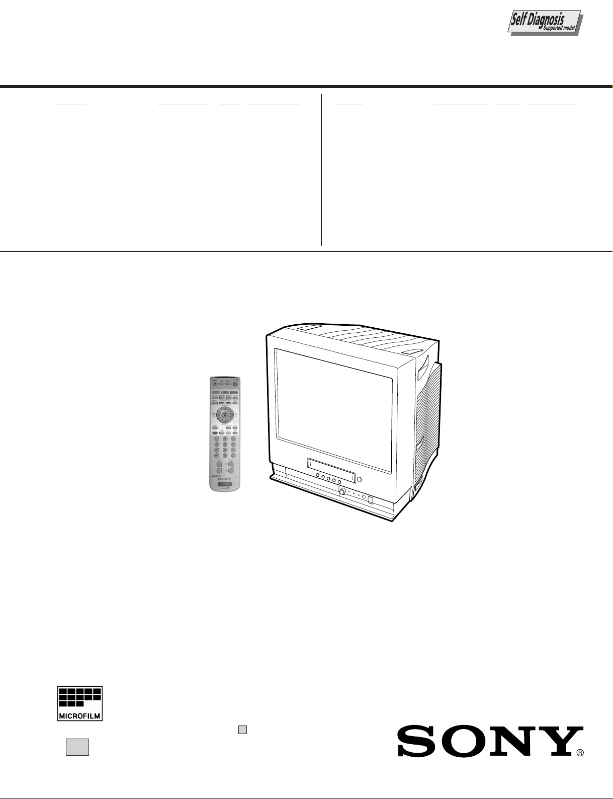
14
FD TRINITRON® COLOUR VIDEO TV

SPECIFICATIONS
TV Section
TV system:
I
Colour system:
PAL, SECAM
NTSC 3.58, 4.43 (only Video In)
Channel Coverage:
UHF: B-21, B69
Picture Tube:
• KV-14FV1U:
Flat Display Trinitron.
14” (approx. 37 cm. measured diagonally)
• KV-21FV1U:
Flat Display Trinitron.
21” (approx. 55 cm. measured diagonally)
VCR Section
Format:
VHS Standard
Video recording system:
Rotary 2-head helical scanning system
Audio recording system:
Monaural
Video signal:
This Video TV is designated to receive TV
programmes based on PAL (I) colour system and to
record and play on PAL system. The Video TV can
also play tapes on NTSC colour system.
Tape speed:
PAL:
SP: 23.39 mm/sec.
LP: 11.70 mm/sec.
NTSC (playback only):
SP: 33.35 mm/sec.
LP: 11.12 mm/sec.
Maximum recording time:
SP: 4 hours with E-240 tape
LP: 8 hours with E-240 tape
General
Rear Terminals
:1/ 21-pin scart connector (CENELEC standard)
including audio/video input, RGB input, TV
audio/video output.
Front Terminals
…2 video input – phono jack
2
audio input – phono jack
headphones jack
Clock
Quartz locked
Clock back up
Approx. 7 days
Power requirements
220-240 V AC, 50Hz
Sound Output:
1 x 6W (music power)
1 x 3W (RMS Mono)
Power Consumption:
• KV-14FV1U: 86 W
• KV-21FV1U: 107 W
Standby Power Consumption:
< 2 W
Dimensions:
• KV-14FV1U: Approx. 375 x 398 x 407 mm.
• KV-21FV1U: Approx. 489 x 500 x 477 mm.
Weight:
• KV-14FV1U: Approx. 15.6 Kg.
• KV-21FV1U: Approx. 27.2 Kg.
Accessories supplied:
1 Remote Control (RM-C815)
2 Batteries (IEC designated)
Other features:
Teletext, Fastext, TOPtext
Sleep Timer
Wake UP Timer
Parental Lock
Auto Head Cleaner
Dial Timer
VideoPlus+
Design and specifications are subject to change without notice.
– 2 –

TABLE OF CONTENTS
Section Title Page Section Title Page
SELF DIAGNOSIS FUNCTION...................................... 4
[ TV SECTION]
1. GENERAL ......................................................... 7
2. DISASSEMBLY
2-1. Rear Cover Removal ............................................... 16
2-2. Chassis Assy Removal ............................................ 16
2-3. Service Position (A Board) ..................................... 16
2-4. A Board Removal .................................................... 16
2-5. Harnes Location ...................................................... 17
2-6. Picture Tube Removal ............................................. 18
3. SET-UP ADJUSTMENTS
3-1. Beam Landing ......................................................... 19
3-2. Convergence ............................................................ 20
3-3. Focus Adjustment .................................................... 21
3-4. Screen (G2) Adjustment .......................................... 21
3-5. White Barance Adjustment ..................................... 22
3-6. Picture Distortion Adjustment ................................. 22
4. CIRCUIT ADJUSTMENTS
4-1. Adjustments with Commander ................................ 23
4-2. Adjustment Method ................................................. 24
4-3. Service Data ............................................................ 25
4-4. A Board Adjustment................................................ 26
5. DIAGRAMS
5-1. Block Diagrams ....................................................... 27
5-2. Circuit Boards Location .......................................... 33
5-3. Printed Wiring Boards and Schematic Diagrams .... 33
• A Board .................................................................... 34
• CVM Board .............................................................. 41
6. EXPLODED VIEWS
6-1. Picture Tube ............................................................ 77
6-2. Chassis ..................................................................... 78
7. ELECTRICAL PARTS LIST...................................... 82
[ VIDEO SECTION]
1. GENERAL ....................................................................... 46
2. DISASSEMBL Y ............................................................. 47
3. CIRCUIT ADJUSTMENTS ........................................ 48
4. INTERFACE, IC PIN FUNCTION
DESCRIPTION .............................................................. 51
5. DIAGRAMS..................................................................... 55
6. EXPLODED VIEWS ..................................................... 79
7. ELECTRICAL PARTS LIST...................................... 90
CAUTION
SHORT CIRCUIT THE ANODE OF THE PICTURE TUBE AND
THE ANODE CAP TO THE METAL CHASSIS, CRT SHIELD, OR
CARBON PAINTED ON THE CRT, AFTER REMOVING THE
ANODE.
SAFETY-RELATED COMPONENT WARNING!!
COMPONENTS IDENTIFIED BY SHADING AND MARK ! ON
THE SCHEMA TIC DIA GRAMS, EXPLODED VIEWS AND IN THE
P ARTS LIST ARE CRITICAL FOR SAFE OPERATION. REPLA CE
THESE COMPONENTS WITH SONY PARTS WHOSE PART
NUMBERS APPEAR AS SHOWN IN THIS MANUAL OR IN
SUPPLEMENTS PUBLISHED BY SONY. CIRCUIT
ADJUSTMENTS THAT ARE CRITICAL FOR SAFE OPERATION
ARE IDENTIFIED IN THIS MANUAL. FOLLOW THESE
PROCEDURES WHENEVER CRITICAL COMPONENTS ARE
REPLACED OR IMPROPER OPERATION IS SUSPECTED.
ATTENTION
APRES AVIOR DECONNECTE LE CAP DE L'ANODE,
COURTCIRCUITER L'ANODE DU TUBE CATHODIQUE ET CELUI
DE L'ANODE DU CAP AU CHASSIS METALLIQUE DE
L'APPAREIL, OU AU COUCHE DE CARBONE PEINTE SUR LE
TUBE CATHODIQUE OU AU BLINDAGE DU TUBE CATHODIQUE.
ATTENTION AUX COMPOSANTS RELATIFS À LA SÉCURITÉ!!
LES COMPOSANTS IDENTIFIÉS PAR UNE TRAME ET PAR UNE
MARQUE ! SUR LES SCHÈMAS DE PRINCIPE, LES VUES
EXPLOSÈES ET LES LISTES DE PIECES SONT D'UNE
IMPORTANCE CIRTIQUE POUR LA SÈCURITÈ DU
FONCTIONNEMENT. NE LES REMPLACER QUE PAR DES
COMPOSANTS SONY DONT LE NUMÈRO DE PIÈCE EST
INDIQUÈ DANS LE PRÈSENT MANUEL OU DANS DES
SUPPLÈMENTS PUBLIÈS PAR SONY. LES RÉGLAGES DE
CIRCUIT DONT L’IMPORTANCE EST CRITIQUE POUR LA
SÉCURITÉ DU FONCTIONNEMENT SONT IDENTIFIÉS DANS LE
PRÉSENT MANUEL. SUIVRE CES PROCÉDURES LORS DE
CHAQUE REMPLACEMENT DE COMPOSANTS CRITIQUES, OU
LORSQU’UN MAUVAIS FONCTIONNEMENT EST SUSPECTÉ.
– 3 –
SELF DIAGNOSTIC FUNCTION
1. OUTLINE
• The units in this manual contain a self-diagnostic function.
• If an error occurs, the STANDBY lamp will automatically begin to flash.
The number of times the lamp flashes translates to a probable source of the problem. A definition of the STANDBY lamp
flash indicators is listed in the instruction manual for the user’s knowledge and reference.
• If an error symptom cannot be reproduced, the remote commander can be used to review the failure occurrence data
stored in memory to reveal past problems and how often these problems occur.
2. DIAGNOSTIC TEST INDICAT ORS
• When an errors occurs, the STANDBY lamp will flash a set number of times to indicate the possible cause of the problem.
If there is more than one error, the lamp will identify the first of the problem areas.
• Result for all of the following diagnostic items are displayed on screen. No error has occured if the screen displays a “0”.
Diagnostic
Item
Description
• Power does not
turn on
• +B overcurrent
(OCP) or
overvoltage
(OVP)
• Vertical deflection
stopped
• White balance
failure (no
PICTURE)
No. of times
STANDBY lamp
flashes
Does not light
2 times
4 times
5 times
Self-diagnostic
display/Diagnostic
result
—
2 : 0 or
2 : 1
at the same
4 : 1
time
(Note 1)
4 : 0
or
4 : 1
5 : 0
or
5 : 1
Probable
Cause
Location
• Power cord is not plugged
in.
• Fuse is burned out F1701
• FBT
• Q802 (H OUT) shorted
• IC501
• IC301 !¢ pin
• IC606
• Q802 (H OUT) shorted
• Q803
• Q608
• R803 open
•CRT
• IC301
• Q701 - Q717
(CVM board)
• G2 is improperly adjusted.
(Note 2)
Detected
Symptoms
• Power does not come on.
• No power is supplied to the
TV.
• AC power supply is faulty.
• On standby state.
• Load on power line is
shorted
(at the same time 4 : 1 on
display).
• Has entered standby state
after horizontal raster.
• Vertical deflection pulse is
stopped.
• Horizontal deflection
stopped.
• Power line is shorted or
power supply is stopped.
• No raster is generated.
• CRT cathode current
detection reference pulse
output is small.
Note 1: If a + B overcurrent is detected, stoppage of the vertical deflection is detected simultaneously.
The symptom that is diagnosed first by the microcontroller is displayed on the screen.
Note 2: Refer to screen (G2) Adjustment in section 3-4 of this manual.
• VCR EMG code List
Code Coutents
00h NO EMG
10h CAM encode NG during unloading
11h CAM encode NG during unloading
12h CAM encode NG at intial
20h T reel NG during unloading
21h S reel FG NG
22h T reel FG NG
23h S reel FG NG
24h T reel FG NG at initial
25h S reel FG NG at initial
Code Coutents
30h Capstan FG NG at initial
31h Capstan FG NG
40h Drum FG NG
41h Drum FG NG at initial
42h Drum FG NG
43h Drum PG NG
44h Drum PG NG
50h DEW
60h FL NG
70h DEW eject NG
– 4 –
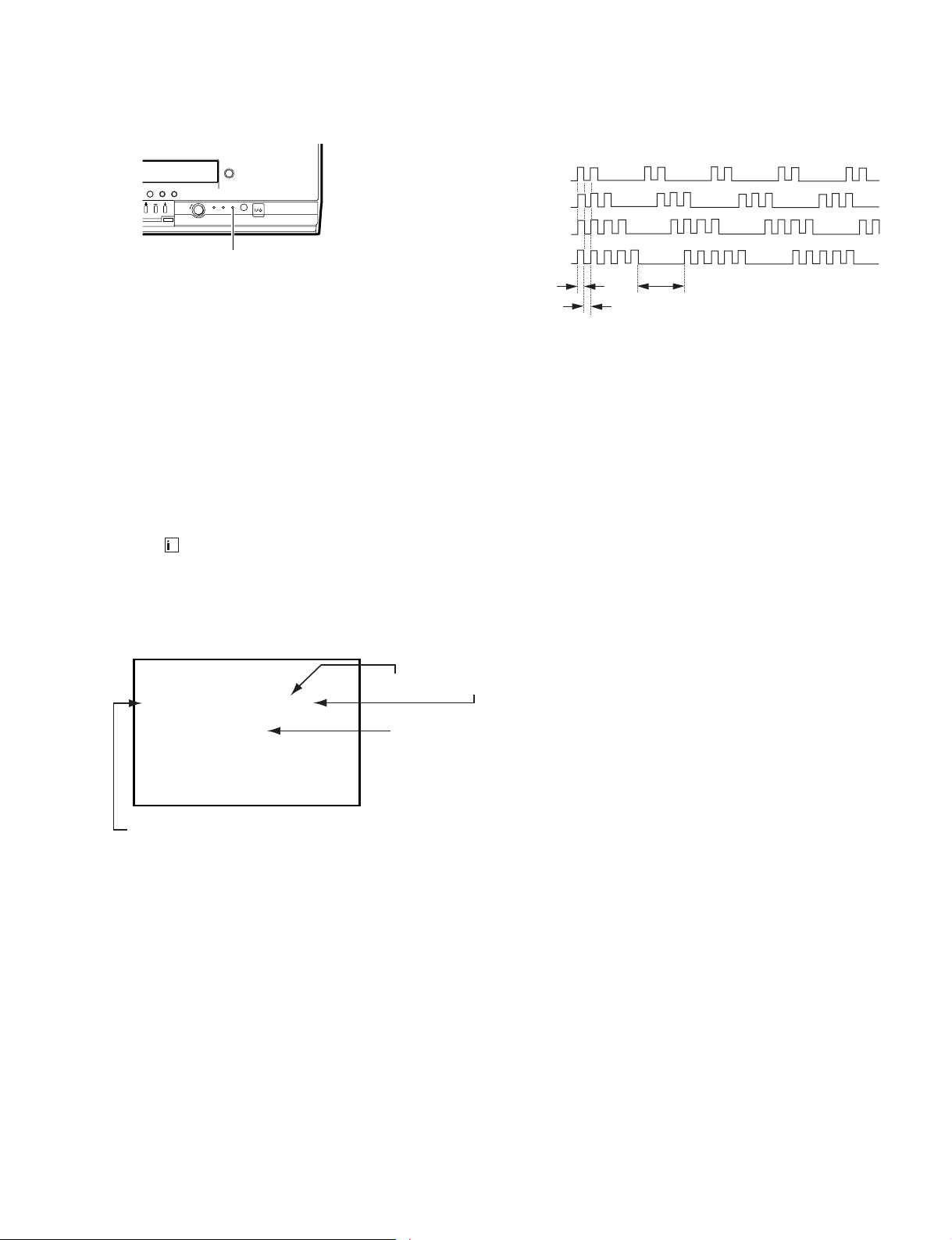
3. DISPLA Y OF STANDBY LIGHT FLASH COUNT
* One flash count is not used for self-diagnostic.
< Diagnostic Item >
• +B OCP/OVP
• White balance failure
STOPPING THE STANDBY FLASH
• Turn off the power switch on the TV main unit or unplug the power cord from the outlet to stop the STANDBY lamp from flashing.
• Vertical deflection stopped
2 times
4 times
5 times
Lamp ON 0.3 sec.
Lamp OFF 0.3 sec.
Lamp OFF 3.0 sec.
< Flash Count >
P
PUSH
STANDBY lamp (RED)
TEMER REC REC
4. SELF-DIAGNOSTIC SCREEN DISPLAY
• For errors with symptoms such as “power sometimes shuts off” or “screen sometimes goes out” that cannot be confirmed,
it is possible to bring up past occurances of failure for confirmation on the screen:
[To Bring Up Screen Test]
• In standby mode, press buttons on the remote commander sequentially in rapid succession as shown below:
[Screendisplay] / channel [5] / Sound volume [-] / Power ON u
+
˘
Note that this differs from entering the service mode (mode volume [+]).
Self-Diagnosis screen display
SELF CHECK
1: 2 : 1 3 : 4 : 0 5 : 1
-- --
VCR :
Note: Though "1: , 3:" indicated, not using.
diagnostic item : result
EMG code.
Numeral "0" means that no fault has been detected.
Numeral "1" means a fault has been detected.
5. HANDLING OF SELF-DIAGNOSTIC SCREEN DISPLAY
• Since the diagnostic results displayed on the screen are not automatically cleared, always check the self-diagnostic
screen during repairs. When you have completed the repairs, clear the result display to “0”.
• Unless the result display is cleared to “0”, the self-diagnostic function will not be able to detect subsequent faults after
completion of the repairs.
[Clearing the result display]
• To clear the result display to “0”, press buttons on the remote commander sequentially as shown below when the diagnos-
tic screen is being displayed.
• Pay attention when perform by the service mode, other all electric adjustment data will be rewrite.
Channel [8] / [0]
[Quitting Self-diagnostic screen]
• To quit the entire self-diagnostic screen, turn off the power switch on the remote commander or the main unit.
– 5 –
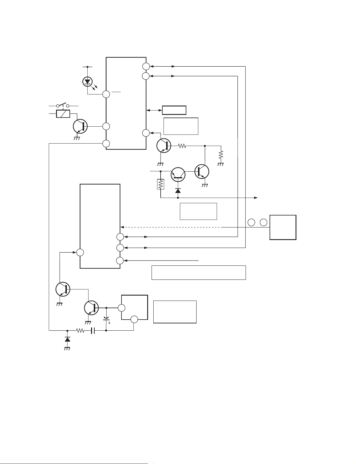
6. SELF-DIAGNOSTIC CIRCUIT
RY603
RELAY
Q601
V•STOP
LED flash
STANDBY
34
21
lamp
D1304
IC301
Y/C/J
53
LED
62
VCR PWR
60
V PULSE
SDA
IC001
µ-COM
35
SCL1
SDA1
OVP
+B LINE
49
47
64
R679
To item 2 and 5 via bus line
MEMORY
Over current
Detection(OVP)
✩
IC002
ITEM 2
Q606
R611
Q611
D636
ITEM 2.
Over voltage
Detection(OCP)
Diagnostic screen display
Q612
R656
FBT
(T801)
–
62 62
IC901
TELE TEXT
R • G • B
34
Q502
SCL
IK IN
C504
21
7
IC501
BOOST
VCC
3
CRT
Auto cut-off white balance detection(AKB)
ITEM 3.
Vertical Deflection
output Detection
(V
•
STOP)
ITEM 4.
R,G,B STOP
Q501
D502
15
R510
VM OUT
C505
[+Bovercurrent] Owing to current increase voltage of R679 decrease and that it make Q611 and Q612 to
become LOW and OFF RY601.
[+Bovervoltage] When +B voltage become more than 142.5V, Q611 and Q612 pin become LOW and
RY601 OFF.
[Verticaldeflectionstopped] Detect Vertical deflection Pulse lost by IC001 ^º pin of micro computer.
Mute the picture at !∞ pin of IC301 that performed by Y/C/J.
[Whitebalance] Detect when R.G.B. output wrong level balance of automatic white balance detecting
standard pulse which detect cathode current, or which become low almost.
– 6 –
5
GB
Main Power On/Off
switch
If you turn off the
Video TV by
using this button
and you do not
turn on it again
during 7 days, all
the settings will
be cleared.
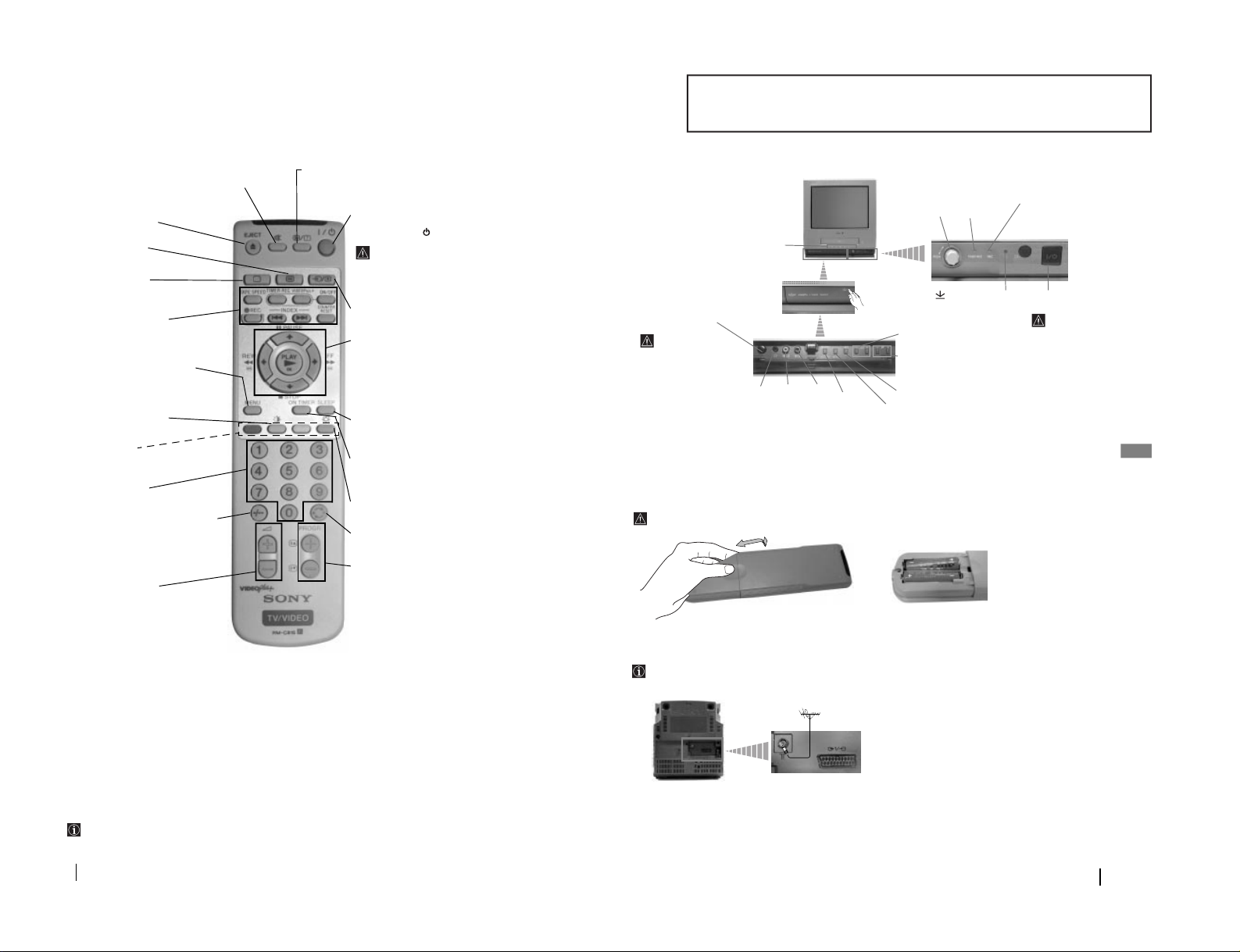
Connecting the Aerial
Connecting cables are not supplied.
Inserting Batteries into the Remote Control
Make sure to insert the supplied batteries using the correct polarities.
Always remember you dispose of used batteries in an environmental friendly way.
Overview of Video TV Buttons
Overview-Installation
Video
Input
jack
Audio
Input
jack
TIMER
REC
(recording)
on/off
button (see
page 13)
REC (Recording)
button (see page11)
Selecting Input source
Volume control buttons
Programme Up or Down
Buttons (Selects TV channels)
DIAL TIMER
(see page 12)
TIMER REC
(recording)
indicator (see
page 13)
REC
(recording)
button (see
page 11)
Standby
indicator
Headphone
jack
Tape transport buttons
(see page 10).
Press on the mark
on the
front of the Video TV to reveal
the front control panel.
Standby on/off
button
By using this
button to turn off
the Video TV
instead of the Main
Power on/off
button, settings
will not be cleared
unless that the
power is
interrupted or you
disconnect the AC
power cord. In that
case settings will
be cleared after 7
days.
4
Descripción general de los botones del Retroproyector
Comprobación de los accsorios suministrados
Descripción general de los botones del RetroproyectorDescripción general de los botones del Retroproyector
Overview
Overview of Remote Control Buttons
Ejecting a videotape
Press to eject the videotape
Selecting Teletext
Press to switch on teletext.
Selecting TV mode
Press to switch off teletext or
video input.
VCR Operation buttons
For details refer to “VCR Operation” section
of this instruction manual.
Displaying the menu system
Press to display the menu on the TV screen.
Press again to remove the menu display from
the TV screen.
Selecting Picture mode
Press repeatedly to change the picture mode.
Fastext buttons
For details refer to “Teletext” section of this
instruction manual.
Selecting channels
Press to select channels.
For double-digit programme numbers, e.g.
23, press -/-- first, then the buttons 2 and 3.
If you enter an incorrect first digit, this
should be corrected by entering another digit
(0-9) and then selecting -/-- button again to
enter the programme number of your choice.
Adjusting TV volume
Press to adjust the volume of the TV.
Temporally Switch Off the Video TV
Press to temporarily switch off the Video TV (the
standby indicator on TV lights up). Press again
to switch on the Video TV from standby mode.
By using this button to turn off the Video TV
instead of the Main Power on/off button,
settings will not be cleared unless that the
power is interrupted or you disconnect the
AC power cord. In that case settings will be
cleared after 7 days.
Selecting input source
Press repeatedly until the desired input symbol of
the source appears on the TV screen.
•
When MENU is switched on:
Use these buttons to operate the menu system. For
details refer to “Introducing and Using the Menu
System” of this instruction manual (see page 7).
•
When MENU is switched off and a tape is inserted:
Use these buttons to operate VCR. For details refer
to “Playing a Tape and Additional Tasks” section
of this instruction manual (see page 10).
Sleep Timer
For details refer to “Switching Off the Video TV
Automatically (Sleep Timer)” section of this
instruction manual (see page 9).
On Timer
For details refer to “Switching On the Video TV
Automatically (On Timer)” section of this instruction
manual (see page 9).
Selecting the TV Screen format
Press to view programmes in 16:9 mode. Press again
to return to Normal (4:3) mode.
Back to the channel last watched
Press to watch the last channel selected (watched for
at least 5 seconds).
Selecting channels
Press to select the next or previous channel.
Besides TV functions, all buttons with green symbols are also used for Teletext operation. For more details, please refer to
"“Teletext” section of this instruction manual (see page 18).
Muting the Sound
Press to mute TV sound. Press
again to restore the sound.
Displaying on Screen information
Press once to display On-Screen indications (first level).
Press twice to display On-Screen indications (second
level)
Press a third time to cancel.
– 7 –
SECTION 1
GENERAL
The operating instructions mentioned here are partial abstracts from the
Operating Instruction Manual. The page numbers of the Operating Instruction Manual remein as in the manual.
6
Switching On the Video TV and Automatically Tuning
The first time you switch on your TV, a sequence of menu screen appear on the TV enabling you to: 1) choose the language of the
menu screen, 2) search and store all available channels (TV Broadcast), 3) change the order in which the channels (TV Broadcast)
appear on the screen and 4) confirm the clock setting.
However, if you need to change any of these settings, you can do that by selecting the appropriate menu in the (Set Up).
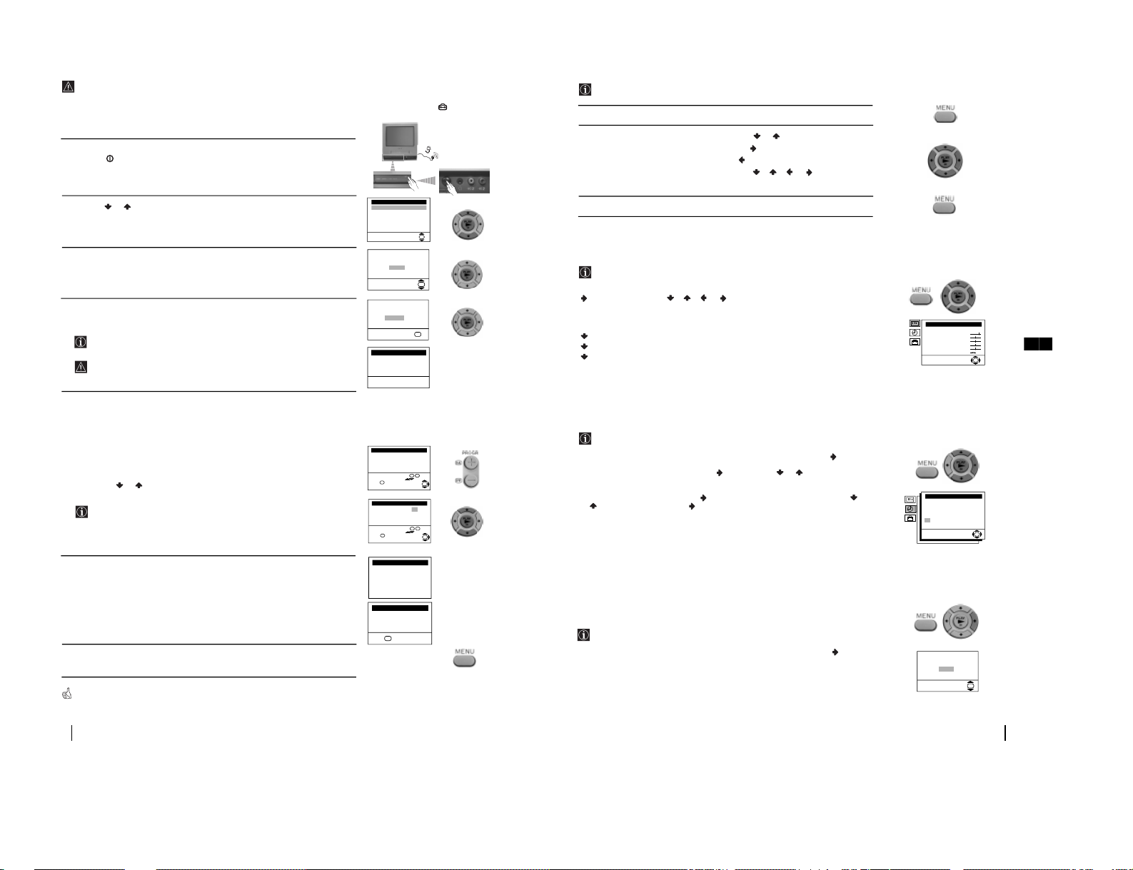
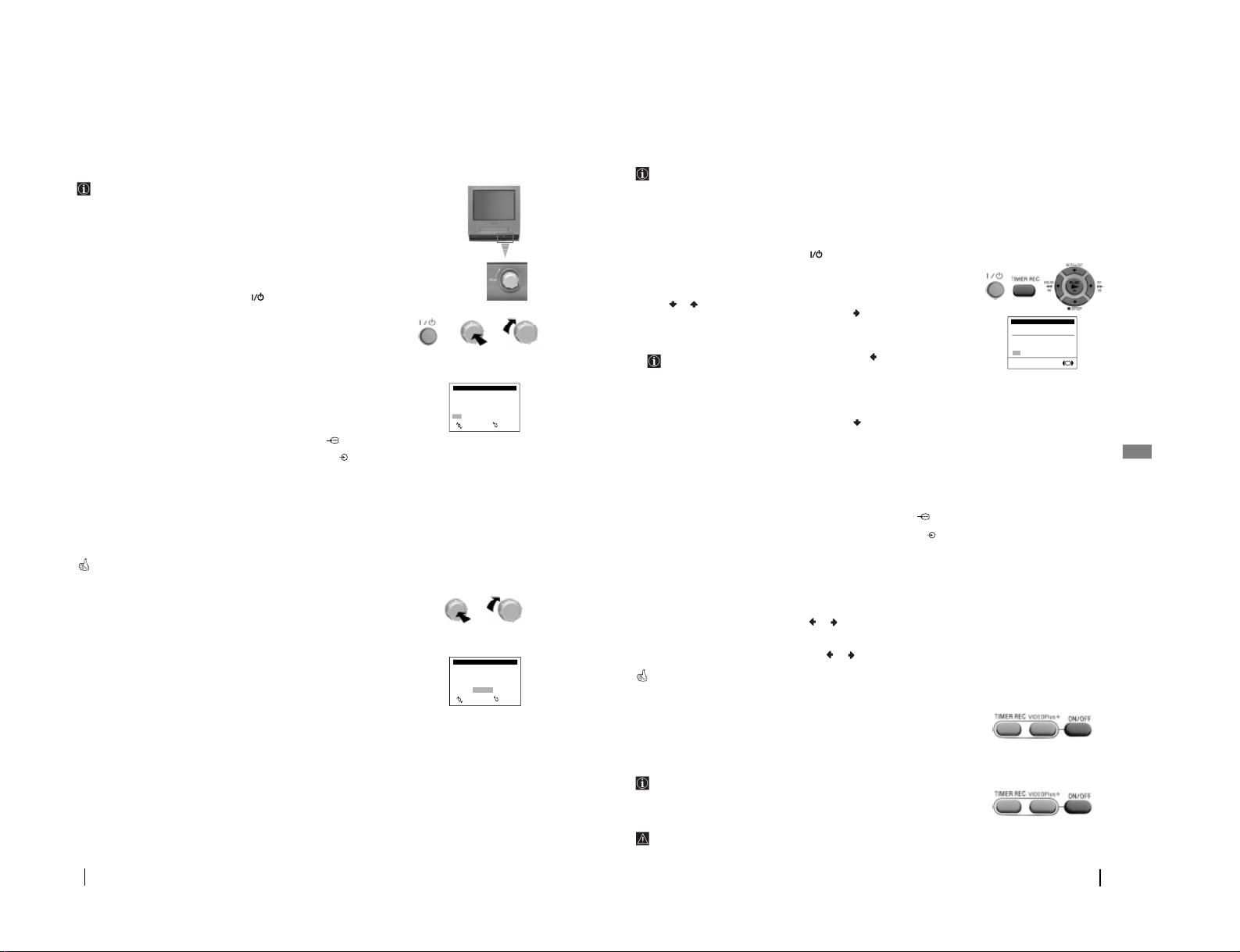
First Time Operation
1
Connect the TV plug to the mains socket (220-240V AC, 50Hz)
Press the main on/off button on the TV set to turn on the Video TV.
The first time you press this button, a Language menu displays automatically on the
TV screen.
2
Press the or button on the remote control to select the language, then press the
OK
button to confirm your selection. From now on all the menus will appear in the
selected language.
3
The Auto Tuning menu appears on the screen. Press the OK button to select Yes .
4
A new menu appears on the screen asking you to check that the aerial is connected.
Ensure the aerial is connected and then press the OK button.
The Video TV starts to automatically search and store all available channels
(TV Broadcast) for you.
This procedure could take some minutes. Please be patient and do not press
any button. Otherwise the automatic tuning will not be completed.
5
After all available channels are captioned and stored, the Programme Sorting menu
appears automatically on the screen enabling you to change the order in which the
channels appear on the screen.
a)
If you do not wish to change the channel order, press OK and go to step 6.
b)
If you wish to change the channel order:
1
Press the PROGR + or - button to select the programme number with the channel
(TV Broadcast) you wish to rearrange appears on the screen.
2
Press the or button to select the new programme number position for your
selected channel (TV Broadcast), then press the OK button.
The word Confirm is highlighted for a few seconds to confirm that the new
programme position is stored.
3
Repeat steps b)1 and b)2 if you wish to change the order of the other channels.
4
When you finish to rearrange the order of the channels, press OK .
6
The Video TV adjusts itself automatically clock setting, and after few seconds date
and time settings are displayed.
If you want to change the time settings, you can adjust it manually through the
menu system (for details, see “Setting the Clock Manually” section of this
instruction manual (see page 7).
7
Press the MENU button to remove the menu from the screen.
Your Video TV is now ready for use
Language
Select Language:
English
Deutsch
Netherlands
Français
Italiano
Español
Português
OK
Do you want to start
automatic tuning?
Yes
No
OK
Please confirm that
aerial is connected
Confirm
OK
Programme: 01
System: I
Channel: C21
Auto Tuning
Searching...
23.09.2000 SAT 12:00
Auto Clock Set
Exit:
OK
Programme: 02 -> 04
Confirm:
Programme Sorting
Select channel: PROG + Select new position:
Exit:
OK
OK
Adjusting Clock...
Auto Clock Set
Programme: 01 -> 01
Confirm:
Programme Sorting
Select channel: PROG + Select new position:
Exit:
OK
OK
7
GB
Introducing and Using the Menu System
Your Video TV uses an on-screen menu system to guide you through the operations. Use the following buttons on the
Remote Control to operate the menu system:
Menu System - TV Operation
1 Press the MENU button to switch the first level menu on.
2• To highlight the desired menu or option, press or .
• To enter to the selected menu or option, press .
• To return to the last menu or option, press .
• To alter settings of your selected option, press //or.
• To confirm and store your selection, press OK.
3 Press the MENU button to remove the menu from the screen.
Picture Adjustment
The “Picture Adjustment” menu allows you to alter the picture adjustments.
To do that: by using the menu system and after selecting the item you want to alter press
, then press repeatedly//orto adjust it and finally press OK to store the
new adjustment.
This menu also allows you to customise the picture mode based on the programme you
are watching:
Live
(for live broadcast programmes).
Movie
(for films).
Personal
(for individual settings).
• Brightness, Colour and Sharpness can only be alterated if “Personal” mode is selected.
• Hue is only available for NTSC colour signal (e.g: USA video tapes).
• Select Reset and press OK to reset the picture to the factory preset levels.
Setting The Clock Manually
The “Clock” option in the “Timer” menu allows you to set manually the clock
whilst you are in TV mode.
To do that: by using the menu system and after selecting the option press , then :
1
With Auto Adjust highlighted, press and next press or to select Off. Next
press OK.
2 Select Manual Adjust and press . With the day column highlighted, press or
to set the date, then press and proceed in the same way to set the month, year,
hour and minutes. Finally press OK.
• II t is important you to set correctly the clock to use Timer Recording, Quick-Timer recording and On
Timer functions.
• If power is interrupted or you turn off the Video TV by using the main On/off power switch or you
disconnect the AC power cord, after 7 days will cause these settings to be cleared.
• To automatically set the clock, and whilst you are in TV mode select “Auto Adjust” “On” in the step above
and in the “Programme” option select the from which programme number you want to get the time.
• Because the Video TV gets clock settings from teletext signals (sent by broadcasters), even you have selected
Auto Adjust “On”, we recommend you to check after summertime and wintertime that clock settings are
correct, if not adjust it manually.
Automatically Tuning The Video TV
The “Auto Tuning” option in the “TV Set Up” menu allows you to automatically
search for and store all available TV channels.
To do that: by using the menu system and after selecting the option, press and then
proceed in the same way as in the section “Switching On the Video TV and
Automatically Tuning”. (see page 6, steps 3 and 4).
Do you want to start
automatic tuning?
Yes
No
OK
Picture Adjustment
Mode: Personal
Contrast
Brightness
Colour
Sharpness
Hue
Reset
OK
Clock 23-09-2000 15:00
Auto Adjust: Off
Clock Programme: 03
Manual Adjust:
23 09 2000 SAT 15:00
OK
– 8 –
8
TV Operation
Changing The Programme Order Of The
TV Channels
The “Programme Sorting” option in the “TV Set Up” menu allows you to change
the order in which the channels (TV Broadcast) appear on the screen.
To do that: by using the menu system and after selecting the option, press and then
proceed in the same way as in the section “Switching On the Video TV and
Automatically Tuning” (see step 5b) on page 6).
Manually Tuning The TV
The “Manual Programme Preset” option in the “TV Set Up” menu allows you to
preset channels one by one to the programme order of your choice. To do that:
1 By using the menu system and after selecting the ”Manual Programme Preset”
option, press . Then with Programme option highlighted press . Press or
to select on which programme number you want to preset the channel. Then press
.
2 After selecting the Channel option, press . Then press or to select the
channel tuning (“C” for terrestrial channels or “S” for cable channels). Next press .
After that, press the number buttons to enter directly the channel number of the TV
Broadcast. If you do not know the channel number, press or to search for it.
When you tune the desired channel, press OK twice to store.
• Repeat all the above steps to tune and store more channels.
Fine Tuning Channels
Normally the Automatic Fine Tuning (AFT) is operating, however by using the
“Manual Programme Preset” option in the “TV Set Up” menu you can manually
fine tune the Video TV to obtain a better picture reception in the case that the
picture is distorted.
To do that: while watching the channel (TV Broadcast) you wish to fine tune, and by
using the menu system select the “Manual Programme Preset” option. Press . With
the AFT option highlighted, press . Next press or to adjust the fine tuning
between -15 and +15. Finally press OK twice to store.
Skipping Programme Positions
The “Manual Programme Preset” option in the “TV Set Up” menu allows you to
skip any unwanted programme numbers when they are selected with the PROGR
+/- buttons.
To do that: by using the menu system and after selecting the “Manual Programme
Preset” option, press . Then with the Programme option highlighted press . Next,
press or to select the programme number you want to skip. Press . Then, select
the Skip option and press . Next press or to select Yes. Finally press OK twice
to confirm and store.
• To cancel this function afterwards, select “No” instead of “Yes” in the step above.
Setting Pay-TV Channels
The “Manual Programme Preset” option in the “TV Set Up” menu allows you to
watch Pay-TV channels by connecting a Pay-TV decoder to the Scart connector
:1/ placed on the rear of the Video TV.
To do that: by using the menu system and after selecting the “Manual Programme
Preset” option, press . Then with the Programme option highlighted, press . Next
press or to select the programme number with the scrambled channel and press
. Select the Decoder option and press . Next press or to select On. Finally,
press OK twice to confirm and store.
• While you are recording a programme which is being recorded through the Pay-TV decoder, you will not
be able to view other programmes through the decoder.
Programme Sorting
Programme: 01 -> 01
Confirm:
Select channel: PROG + Select new position:
OK
Manual Programme Preset
Programme:
System:
Channel:
AFT:
Skip:
Decoder:
Confirm
OK
01
I
C 21
On
No
Off
Manual Programme Preset
Programme:
System:
Channel:
AFT:
Skip:
Decoder:
Confirm
OK
01
I
C 21
On
No
Off
Manual Programme Preset
Programme:
System:
Channel:
AFT:
Skip:
Decoder:
Confirm
OK
01
I
C 21
On
No
Off
Manual Programme Preset
Programme:
System:
Channel:
AFT:
Skip:
Decoder:
Confirm
OK
01
I
C 21
On
No
Off
9
GB
Selecting The Language Of The Menu
Screens
The “Language” option in the “Set Up” menu allows you to select the language
that the menus are displayed in.
To do that: by using the menu system and after selecting the option, press and then
proceed in the same way as in the section “Switching On the TV and Automatically
Tuning” (see page 6, step 2).
Locking The Video TV
The “Parental Lock” option in the “Set Up” menu allows you to lock the buttons of
the Video TV set. In this way, after this option is selected and the Video TV set is
switched off, the buttons on the Video TV only works by using the remote control
buttons.
To do that: by using the menu system and after selecting the option, press . Then
press or to select On. Press OK to confirm and store and finally press .
• To cancel this function afterwards, select “Off” instead of “On” in the step above.
• If you have locked your Video TV and the remote commander is lost, press the
button (during more
than 5 seconds) on the set to operate it.
Adjusting The Picture Rotation
(only for KV-21FV1U)
Because of the earth’s magnetism, the picture might be slant. In this case, you can
correct the pictures slant by using the option “Picture Rotation” in the “Set Up”
menu.
To do that: by using the menu system and after selecting the option, press . Then
press or to correct any slant of the picture between -5 and +5 and finally press OK
to store.
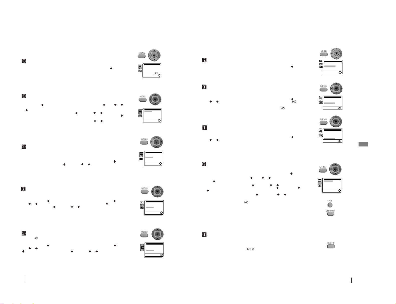
Switching On The Video TV
Automatically (On Timer)
The “On Timer” option in the “Timer” menu allows you to preset your Video TV
to automatically switch on at a desired time. You can select the TV programme or
video playback to be switched automatically on from standby mode.
To do that: by using the menu system and after selecting the option press ,
1 With Time option highlighted, press . Press or to set the on-time hour then
press . Proceed in the same way to set the minutes and press OK.
2 With Source option highlighted, press . Then press or to select the source to
be switched on (“TV” or “VCR”). If you select “TV”, press and then press or
to select the programme number you want the Video TV turns on. Press OK.
3 With On Timer option highlighted, press and then press or to select On.
Press OK.
4 Finally press the standby button . At the selected time, the Video TV switches on
automatically.
• Any loss of power will cause these settings to be cleared.
• By pressing the ON TIMER button on the remote control you can set on/off the On Timer, but it is not
possible to change the time and programme settings.
Switching Off The Video TV
Automatically (Sleep Timer)
You can automatically switch the video TV into standby mode after a selected time
period.
To do that: Press the SLEEP button on the remote control repeatedly to set the time
period delay (OFF, 30, 60 or 90 minutes).
• While watching the TV, you can press the /
button on the remote control to display the time
remaining.
• One minute before the Video TV switches itself into standby mode, a good night message will be displayed
on the screen.
• To cancel this function afterwards, select “Off” in the step above.
TV Operation
Set Up
TV Set Up
VCR Set Up
Language
Parental Lock: Off
VHS: Others
Picture Rotation: 0
OK
Set Up
TV Set Up
VCR Set Up
Language
Parental Lock: Off
VHS: Others
Picture Rotation: 0
OK
Set Up
TV Set Up
VCR Set Up
Language
Parental Lock: Off
VHS: Others
Picture Rotation: 0
OK
On Timer
Time:
Source:
On Timer:
OK
06: 00
TV PROG01
Off
– 9 –
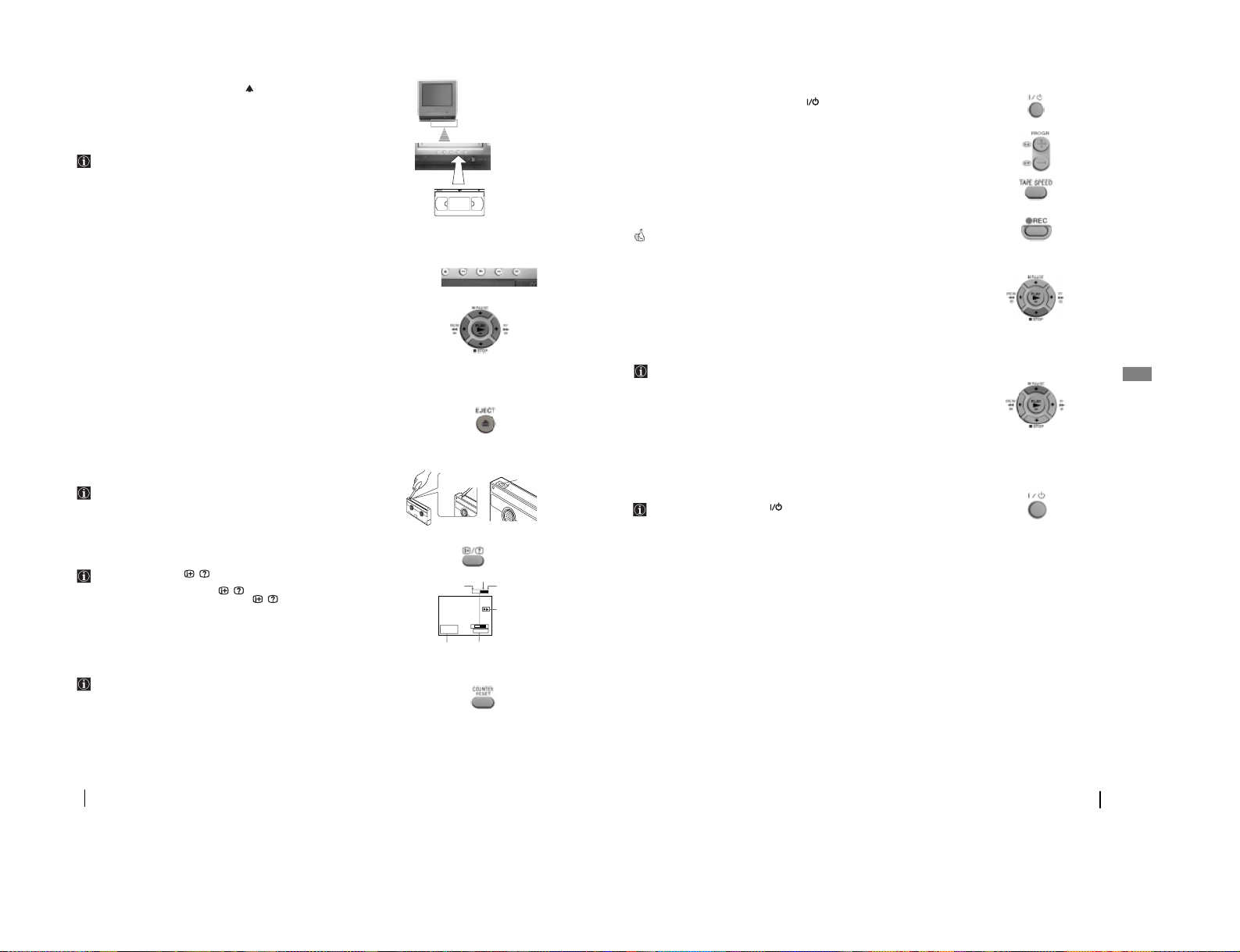
11
GB
Recording TV programmes
1 In standby mode, press the standby button to turn on the Video TV.
2 Insert a cassette with a safety tab.
3 Press PROGR + or –, or the number buttons to select the programme number.
4 Press TAPE SPEED to select the recording speed: SP for Standard Play or LP for
Long Play.
• In the SP mode, the tape runs twice as fast as the LP mode. It means that in LP mode you can record
double time than in SP mode.
5 Press REC
r.
The REC indicator on the front of the Video TV lights up and recording begins.
To stop recording
Press STOP p.
• When the tape reaches the end, the Video TV rewinds the tape automatically to the beginning, then stops.
This function does not work when the power of the Video TV is off.
To pause recording
You can cut out an unwanted scene during recording with this button.
1 Press PAUSE P when an unwanted scene appears on the screen, then recording
pauses.
2 Press PAUSE P again to release the pause mode at the desired scene, then recording
resumes from the point set in step 1.
• When the recording pause mode lasts for about 5 minutes, the Video TV stops recording to prevent tape
damage.
Continues Recording with the TV off
Whilst you are recording, press . The Video TV is turned off. However,
recording continues and the REC indicator on the Video TV lights up.
VCR-Recording
10
VCR-Basic Operations
Playing a tape
1 Insert a cassette with the arrow indication facing upwards.
•If you insert a cassette with its safety tab removed, playback starts automatically.
2 Press PLAY z and the playback starts. On Screen information is displayed for a few
seconds.
Additional Tasks
You can operate all the video tasks by using the remote control buttons or the
Video TV buttons.
To stop playback
Press STOP p and the Video TV returns to the normal TV picture.
To stop playback for a moment
Press PAUSE P. Press it again or press to resume playback.
¥ If you leave your Video TV in pause mode, normal playback resumes after about 5 minutes.
To fast forward or rewind the tape
Press STOP p, then press FF ) to fast forward or press REW 0.
To view the picture in fast forward or rewind mode
Press and hold FF ) during fast forward or REW 0 during rewind. While you hold
the button, you can view the picture.
When you release the button, fast forward or rewind mode is resumed.
If you use the buttons on the remote commander, press FF ) or REW0 once and
will not be necessary to hold the button. In this case to resume normal playback, press
PLAY z.
To search a tape at high speed
During playback, press and hold REW 0 (rewind) or FF ) (fast forward). A high
speed picture appears on the TV screen.
¥ To resume normal playback, release the button.
To eject a cassette
Press EJECT 6.
¥ You can eject the cassette even if the power is in standby mode.
Protecting your cassette against
accidental erasure
To prevent accidental erasure, break off the safety tab as illustrated.
¥ To record on a cassette without a safety tab, simply cover the tab hole with adhesive tape.
Displaying On-Screen Information
In Play mode, press the
/ button to display the following on-screen
information. To show only the amount of remaining tape and the linear
tape counter on the screen, press
/ again.
To make the information disappear, press / repeatedly until no
information is displayed on the screen.
Resetting the tape counter
The tape counter helps you to locate a certain scene after playback.
Press the COUNTER RESET button on the remote control to set the counter to
“00:00:00” before playing the tape. The tape counter is automatically reset to zero
whenever a cassette is inserted. The Video TV keeps counting the length of the tape
being played. Note, however, that the tape counter does not count the portions
without video signals recorded.
Adhesive
tape
Safety tab
4.12THU
E
2:05:10
S
E
S
20:00
SP
Beginning of the tape
Amount of tape remaining
End of the tape
Linear tape counter
Current date and time
or
Insert this side into recorder Do not touch the tape inside
Tape operation mode
– 10 –
12
Recording TV programmes using DIALTIMER
The Dial-Timer recording function allows you to preset your Video TV to record
one programme within a 24 hour period. for setting the Dial-Timer, use DIAL
TIMER button on the Video TV.
Before you begin:
• Make sure that the clock is set correctly. If it is not, refer to the “Setting the Clock
Manually” section of this instruction manual (see page 7).
• Make sure that the loaded cassette has its safety tab intact.
• Make sure that the Video TV does not enter the timer recording standby mode (the
TIMER REC indicator on the Video TV should not be lit).
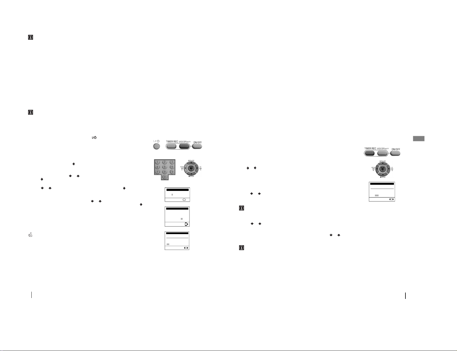
1 In standby mode, press the standby button
to turn on the Video TV.
2 Press DIAL TIMER. The “Dial Timer” menu appears on the screen.
3 Turn DIAL TIMER to set the hour of the start time, then press DIAL TIMER to
confirm.
4 Proceed in the same way as in step 3 to set the minutes of the recording start time, the
recording time period and programme number to be recorded.
• The hour increases or decreases by one hour.
• The minutes increase or decrease by one minute.
• The recording time period increases or decreases by 15 minutes.
• The programme position changes as follows
0 <—> 1 <—> 2... <—> 99 <—> L1 <—> L 2 <—> 0 <—>1
• L1 is used for the equipment connected to the Scart connector
:
1/ placed on the rear
of the Video TV.
• L2 is used for the equipment connected to the front connectors … and .
5 With TAPE SPEED highlighted, turn the DIAL TIMER to select the recording
speed: SP for Standard Play or LP for Long Play, then press the DIAL TIMER.
• In LP mode you can record double time than in SP mode.
6 Turn DIAL TIMER to move the cursor to OK, then press DIAL TIMER to confirm
all the settings.
• If a warning message appear on the screen, the recording is cancelled and after proceed
according the necessities, you must re-enter again the Dial timer settings.
The Dial Timer indicator on the Video TV lights up and the Video TV enters into the timer recording
standby mode.
Changing or Cancelling the Dial Timer settings
1 Press DIAL TIMER.
The Dial Timer menu appears on the screen.
2
Turn DIAL TIMER to CHANGE (to change the recording settings) or to CLEAR (to
clear the recording settings) and press DIAL TIMER.
3 a) If you have selected CLEAR, press DIAL TIMER and all the settings will be
cleared.
b) If you have selected CHANGE, you can change all the settings by following steps
from 2 to 5 of the above section “Recording TV Programmes using DIAL TIMER”.
VCR-Recording
START DURATION PROG
23 22:00
11:00 01
SAT
TAPE SPEED: SP
OK CHANGE CLEAR
Dial Timer 23 SAT 23:00
SELECT
OK
Turn
Press
Turn
Press
START DURATION PROG
23 22:00
11:00 01
SAT
TAPE SPEED: SP
OK CHANGE CLEAR
Dial Timer 23 SAT 23:00
SELECT
OK
13
GB
VCR-Recording
This function allows you to preset your Video TV to record up to 5 programmes
within a one-month period.
Before you begin:
• Make sure that the clock is set correctly. if it is not, please refer to the section “Setting
the Clock Manually”(see page 7).
• Make sure that the loaded cassette has its safety tab intact.
Setting the Timer
1 In standby mode, press the standby button
to turn on the Video TV.
2 Press the TIMER REC button to display the Programme List menu.
3 Press or repeatedly to set the date (for daily and weekly recording, refer to the
section “Daily/Weekly Recording” below), then press .
4 Proceed in the same way as in step 3 to set recording start time, recording stop time,
programme number, tape speed (SP or LP) and VPS/PDC “On” or “Off”.
If you have made a mistake during timer setting, press to return to the
previous position and correct the setting.
• Date:
Daily/Weekly Recording
You can preset your Video TV to record the same programme every day of the
week (daily recording) or the same programme on the same day every week
(weekly recording).
Whilst you are in DATE position, with each press of , the setting changes as
follows:
23 SAT (today) —> MON-SUN —> MON-SAT —> MON-FRI —> SAT (means
every Saturday...) —> FRI —> SUN —> 22 (next month).—>...
• Time:
• The hour increases or decreases by one hour.
• The minutes increase or decrease by one minute.
• Programme number:
• The programme position changes as follows:
0 <—> 1 <—> 2... <—> 99 <—> L1 <—> L 2 <—> 0 <—>1
• L1 is used for the equipment connected to the Scart connector :1/ placed
on the rear of the Video TV.
• L2 is used for the equipment connected to the front connectors
…
and .
• Tape Speed:
• In “LP” mode you can record double than in SP mode
• VPS/PDC:
• For details refer to “Timer recording with VPS/PDC signals” section of this
instruction manual (see page 14).
5 Press OK.
6 If you want to set more programmes, press or to move the cursor to ADD and
then press OK. Repeat steps from 3 to 5.
7 After setting all your desired programmes press or and highlighting OK, press
the OK button to confirm your settings.
The TIMER REC indicator on the Video TV lights up and the Video TV enters into
timer recording standby mode.
To Stop Timer Recording
Press the ON/OFF button on the remote control. Then the TIMER REC indicator on the
Video TV turns off.
Using the Video TV before Timer Recording starts
You can watch a TV programme, check the timer settings and reset the counter in
timer recording standby mode. However, if you want to eject the cassette, use the
tape operation buttons, change or cancel the timer settings, you have to press the
ON/OFF button on the remote control to turn off the TIMER REC indicator on the
Video TV set.
Remember to press again the ON/OFF button to make the TIMER REC indicator
lights up again and the set comes back into the timer recording standby mode.
Recording TV Programmes Using the Timer
VPS
DATE START STOP PROG PDC
23 SAT 22:00 23:00 03 SP ON
OK ADD CHANGE CLEAR
Programme List 23 SAT 20:00
OK
– 11 –
14
Timer recording with VPS/PDC signals
Some broadcasting system transmits VPS (Video Programme System) signals or
PDC (Programme Delivery Control) signals with the TV programmes. These
signals assure you that your timer recordings are made regardless of broadcast
delays, early starts, or broadcast interruptions. For example, if an urgent news
bulletin interrupts a regular programme, recording stops. As soon as the
interrupted programme resumes, recording starts again. To do that:
1
When you set a programme to be recorded by using the timer, (refer to the “Setting
the Timer” section on page 13), set VPS/PDC to On.
•If recording times overlap due to a VPS/PDC time shift, the programme that was broadcast first has
priority. Recording of the second programme begins when the first programme has finished.
•If the Video TV could not receive VPS/PDC signal because it was too weak or because the station
failed to transmit VPS/PDC signals, timer recording is made without the VPS/PDC function.
Recording TV Programmes Using
VideoPlus+ *
VideoPlus+ is a trademark applied for by Gemstar Development Corp. VideoPlus+ system is
manufactured under license from Gemstar Development Corporation.
The VideoPlus+ function allows you to simplify the task of making timer
recordings. Using VideoPlus+, you can make all the necessary settings by just
entering the desired programme’s 9-digit code, which is available in your local
programme guide.
Before you begin:
• Make sure that the loaded cassette has its safety tab.
1
In standby mode, press the standby button to turn on the Video TV.
2
Press the VIDEOPLUS+ button to display the VideoPlus+ menu.
3
Press the number buttons to enter the desired programme’s VideoPlus+ number and
press OK.
• If you have made a mistake, press and re-enter the correct number.
4
On the screen appears automatically date and time recording settings. With PROG
column highlighted, press or to select the correct programme number and then
press .
5 Press or to select the recording speed: SP or LP. Then press .
• In LP mode you can record double time than in SP mode.
6 Highlighting the VPS/PDC column, press or to select On or Off. (for details,
refer to “Timer recording with VPS/PDC signals” section above). Then press .
7 The Programme List menu appears on the screen. If recording settings are correct,
highlighting OK, press the OK button to confirm.
8 If you want to check, add, change or cancel your settings please refer to the
“Checking/Adding/Changing/Cancelling the Timer Settings” section (see page 15).
The TIMER REC indicator on the front of the Video TV lights up and the set enters into timer
recording standby mode.
VCR – Recording
Plus Code
[1 2 6 - - - - - -]
Set 0-9 and press
Video Plus+ 23 SAT 22:00
OK
Plus Code
[1 2 6 1 9 6 3 3 6]
VPS
DATE START STOP PROG PDC
23SAT 22:00 23:00 03 SP ON
Select Programme:
Video Plus + 23 SAT 22:00
OK
VPS
DATE START STOP PROG PDC
23 SAT 22:00 23:00 03 SP ON
OK ADD CHANGE CLEAR
Programme List 23 SAT 20:00
OK
*
15
GB
Guide Station name
channel
001 BBC1
002 BBC2
003 ITV
004 CHANNEL 4
005 RTE (IRELAND)
006 NETWORK 2 (IRELAND)
101 SKY ONE
102 SKY NEWS
103 SKY MOVIES
104 THE MOVIE CHANNEL
105 SKY SPORT
106 NICKELODEON
VH-1 GERMANY
107 EUROSPORT
108 GALAVISION
109 MTV EUROPE
110 CHILDREN´S CHANNEL
THE FAMILY CHANNEL
111 SKY MOVIES GOLD
112 BBC WORLD SERVICE
113 RTL 4
114 SUPER SPORT
FILMNET 2
FILMNET +
115 RTL PLUS INTERNATIONAL
116 SAT 1
117 PREMIERE
118 3 SAT
119 ARD
120 PRO 7
121 TELE 5
122 TELECLUB
Guide Station name
channel
123 UK GOLD
124 DISCOVERY
THE LEARNING CHANNEL
125 BRAVO
ADULT CHANNEL
126 CNN
127 EURONEWS
129 QVC
130 UK LIVING
TV-X
131 RAI 1
132 RAI 2
133 TV5 EUROPE
134 TVE INTERNATIONAL
135 MBC/ARABIC
136 VTM
137 SPORTNET
138 COUNTRY MUSIC TV
139 VIDEO HITS ONE
VH-1
140 SKY SPORT 2 &
SOAPS & TRAVEL
141 TV ASIA
142 LA-5
143 LIVE TV
144 SUPERCHANNEL
145 JAPAN TV
146 SELECT TV
147 MOVIE CHANNEL
FILMNET 1
148 SKY SPORT 3
149 TNT
CARTOON NETWORK
Checking/Adding/Changing/Cancelling
the Timer Settings
1
Press the TIMER REC button on the remote control to display the list of the timer
settings that you preset. If you just want to check the list, go to step 4. If you want to
add, change or clear any setting, please follow all the steps below.
2 Press or repeatedly to select ADD, CHANGE or CLEAR and press OK.
3 a)To add new settings:
Repeat steps from 3 to 7 of the section “Setting the Timer” (see page 13).
b) To change the settings:
Press or repeatedly to move the cursor to the setting you want to change,
then press OK. Finally repeat steps from 3 to 7 of the section “Setting the Timer”
(see page 13).
If you notice you have overlapped timer settings, you can correct the settings as
mentioned above. Otherwise, the second programme starts recording only after
the first programme has finished.
c) To clear the settings:
Press or repeatedly to move the cursor to the setting you want to delete,
then press OK. The setting is cleared and “--“ appears.
4 When you finish adding, changing or cancelling the settings, press or to select
OK and then press the OK button.
If there are other timer setting on the list, the Video TV enters the timer
recording standby mode and the TIMER REC indicator on the Video TV set
lights up.
VCR-Recording
VPS
DATE START STOP PROG PDC
23 SAT 22:00 23:00 03 SP ON
OK ADD CHANGE CLEAR
Programme List 23 SAT 20:00
OK
Guide Channels for VideoPlus+
– 12 –
16
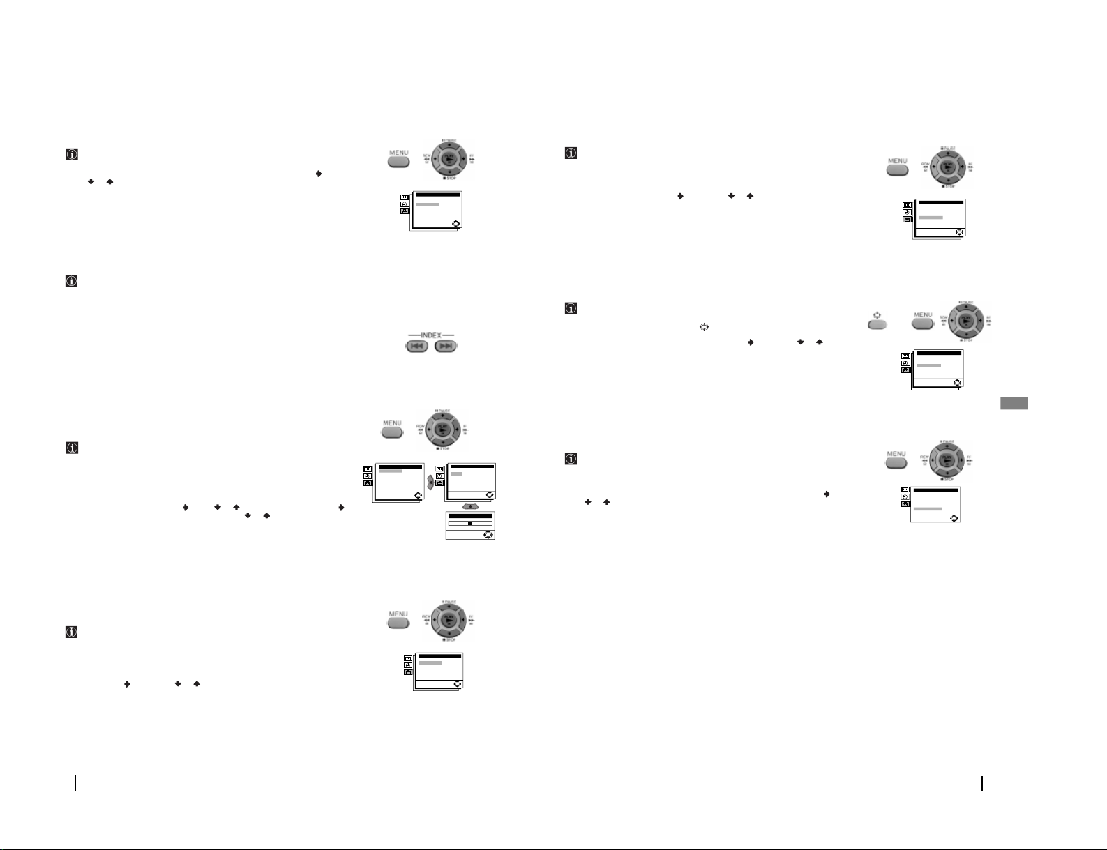
Playing a Tape Repeatedly
The “Auto Repeat ” option in the “VCR Set Up” menu allows you to play a
recorded tape repeatedly.
To do that: by using the menu system and after selecting the option, press . Then
press or to select On. Finally press PLAY z to start the playback. When the tape
reaches its end, the video TV rewinds the tape to the beginning and then, plays it again.
• To cancel this function afterwards, select “Off” instead of “On” in the step above.
Searching Using the Index Function
The Video TV marks the tape with an index signal at the point where each
recording begins. These signals can be used to find a specific recording. this Video
TV can search up to 99 index signals ahead of or behind the current position.
To do that:
1 Insert a tape.
2 Press INDEX = or + repeatedly to specify how many index signals ahead or
behind you want to search in relation to the current tape position. The Video TV
begins searching for the selected index. When the index is reached, playback begins
automatically.
• You can stop searching by pressing STOP p.
Adjusting the Tracking
The tracking condition is automatically adjusted on this Video TV. The AUTO
TRACKING message appears while the Video TV is searching for the best tracking
condition.
However, if streak or snow noise appear on the video playback, you can adjust the
tracking condition manually by using the “Tracking Control” menu in the “VCR
Set Up” menu.
To do that: Whilst you are in play mode and by using the menu system, select the
Tracking Control menu and press . Press or to select Manual and press .
When the tracking meter appears on the screen press or to reduce the picture
noise and get the best picture noise. Finally press OK.
• To cancel this function afterwards, select again “Auto” instead of “Manual” in the step above.
Adjusting the Picture with the
Optimum Picture Control (OPC)
The “OPC” option in the “VCR Set Up” menu allows you to improve playback and
recording quality by adjusting the system parameter automatically according to the
condition of the video tape. The OPC function works on all types of tapes, even on
rental tapes. This function is set to “On” at the factory. To maintain better picture
quality, we recommend to leave the function on.
To do that: Whilst you are in play mode and by using the menu system, select the OPC
option and press . Then press or to select On or Off. Finally press OK.
VCR-Additional Operations
Tracking Control
OK
VCR Set Up
Tracking Control:
OPC:
Auto Repeat
Format:
Colour System:
OK
On
Off
Normal
Auto
VCR Set Up
Tracking Control:
OPC:
Auto Repeat
Format:
Colour System:
OK
On
Off
Normal
Auto
Tracking Control
Auto
Manual
OK
VCR Set Up
Tracking Control:
OPC:
Auto Repeat
Format:
Colour System:
OK
On
Off
Normal
Auto
17
GB
VCR-Additional Operations
Setting the Colour System
The colour system is set in “Auto” condition. However, by using the “Colour
System Option” in the “VCR Set Up” menu allows you to, set the colour system to
the corresponding system that the tape was recorded in the case that you notice
streaks appearing on the screen during playback
To do that: Whilst you are in play mode and by using the menu system, select the
Colour System option and press . Then press or to select the corresponding
colour system (Auto, MESECAM, PAL or NTSC). Finally, press OK.
• To cancel this function afterwards, select again “Auto” in the step above.
Viewing Programmes in 16:9 Mode
When viewing recording of programmes which were originally broadcast in 16:9
mode, you can set your Video TV to 16:9 mode to prevent a distorted picture.
To do that: : Press repeatedly the button on the remote control to select 16:9 or
Normal (4:3 format). You can also do it, by using the menu system. In that case, select
the Format option in the “VCR Set Up” menu and press . Then press or to select
16:9 or Normal. Finally, press OK.
• When you change channels, switch between input sources or turn the power on and off, the Video TV will
switch back to normal mode.
When Connecting to a Sony VCR
If you use this Video TV with another Sony VCR, the remote control may
accidentally operate both the Video TV and VCR at the same time. The VHS option
in the “Set Up” menu allows you that the remote control operates only this Video
TV.
To do that: by using the menu system and after selecting the VHS option, press . Then
press or to select Sony. Finally, press OK.
• To cancel this function afterwards, select “Others” in the step above.
VCR Set Up
Tracking Control:
OPC:
Auto Repeat
Format:
Colour System:
OK
On
Off
Normal
Auto
VCR Set Up
Tracking Control:
OPC:
Auto Repeat
Format:
Colour System:
OK
On
Off
Normal
Auto
Set Up
TV Set Up
VCR Set Up
Language
Parental Lock: Off
VHS: Others
Picture Rotation: 0
OK
or
– 13 –
18
Teletext
Teletext
Teletext is an information service transmitted by most TV stations. The index
page of the teletext service (usually page 100) gives you information on how to
use the service. To operate teletext, use the remote control buttons as indicated
below.
Make sure to use a channel (TV Broadcast) with a strong signal, otherwise
teletext errors may occur.
To Switch On Teletext:
After select the channel (TV Broadcast) which carries the teletext you wish to view,
press .
To Select a Teletext page:
Input 3 digits for the page number, using the numbered buttons.
• If you have made a mistake, retype the correct page number.
• If the counter on the screen continues searching, it is because this page is not available. In
that case, input another page number.
To access the next or preceding page:
Press PROGR + ( ) o PROGR - ( ).
To superimpose teletext on to the TV:
Whilst you are viewing teletext, press . Press it again to cancel teletext mode.
To freeze a teletext page:
Some teletext pages have sub-pages which follow on automatically. To stop them,
press / .
Press it again to cancel the freeze.
To reveal concealed information (e.g: answer to a quiz):
Press / . Press it again to conceal the information.
To Switch Off Teletext:
Press .
Fastext
Fastext service lets you access pages with one button push.
While you are in Teletext mode and Fastext is broadcast, a colour coded menu
appears at the bottom of the teletext page. Press the colour button (red, green,
yellow or blue) to access the corresponding page.
TELETEXT
Index
Programme
News
Sport
Weather
25
153
101
98
TELETEXT
Index
Programme
News
Sport
Weather
25
153
101
98
TELETEXT
Index
Programme
News
Sport
Weather
25
153
101
98
TELETEXT
Index
Programme
News
Sport
Weather
25
153
101
98
TELETEXT
Index
Programme
News
Sport
Weather
25
153
101
98
TELETEXT
Index
Programme
News
Sport
Weather
25
153
101
98
TELETEXT
Index
Programme
News
Sport
Weather
25
153
101
98
TELETEXT
Index
Programme
News
Sport
Weather
25
153
101
98
19
GB
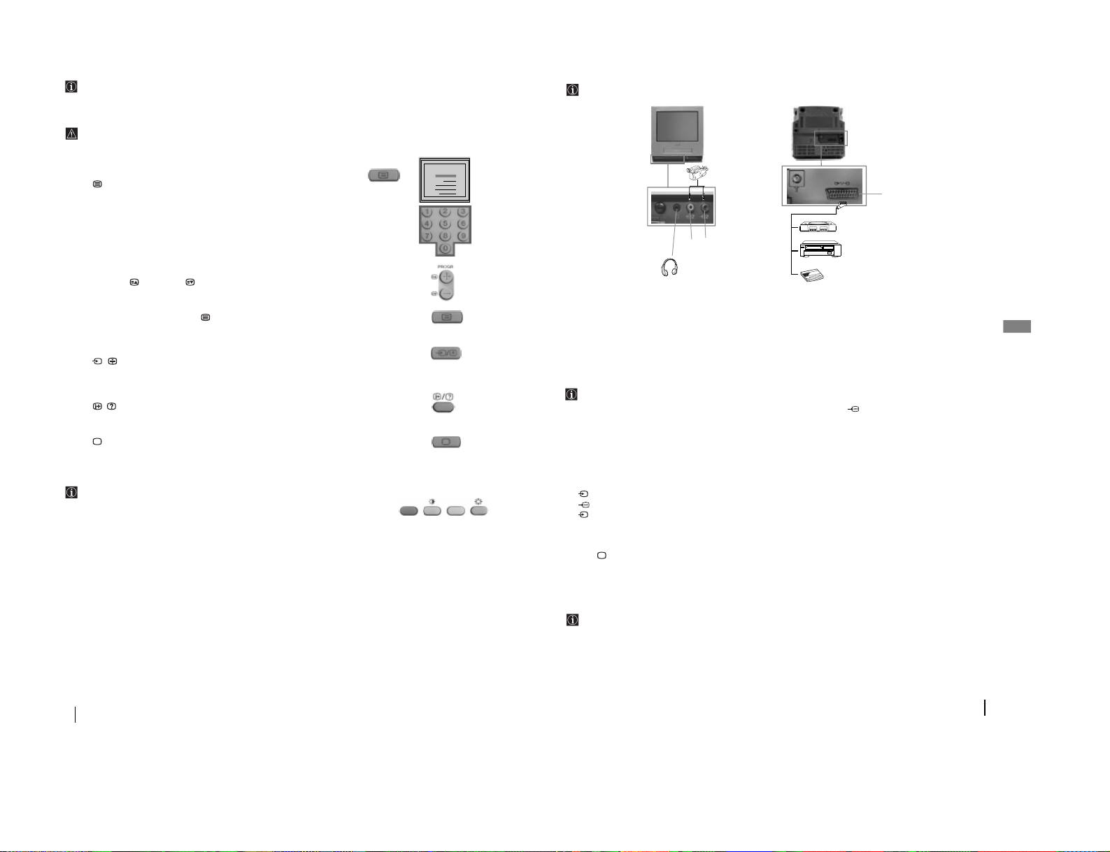
Connecting Optional Equipment
Using the following instructions, you can connect a wide range of optional equipment to your Video
TV set. (Connecting cables are not supplied).
* “PlayStation” is a product of Sony Computer Entertainment, Inc.
* “PlayStation” is a trademark of Sony Computer Entertainment, Inc.
Using Optional Equipment
In order to get the input signal of a connected equipment onto the TV screen, you need to select the
symbol of the connector to which you have connected the device.
e.g.: You have connected a “PlayStation” to the connector with the symbol :1/ . Press the button
… on the remote control repeatedly until you see the symbol
…1 on the screen.
1 Connect your equipment to the designated Video TV socket, as indicated above.
2 To watch the picture of the connected equipment, press the … button repeatedly until the correct input
symbol appears on the screen.
Symbol Input Signals
1 • Audio / video input signal through the Scart connector
C.
• RGB input signal through the Scart connector
C.
2 • Video and audio input signals through the phono sockets
A and B.
3
Switch on the connected equipment.
4 Press button on the remote control to return to the normal TV picture.
Editing with another VCR
Using an additional VCR and connecting as it is in the section above “Connecting Optional
Equipment”, you can edit a tape.
Additional Information
1
2
C
“PlayStation”*
VCR
AB
Decoder
– 14 –
20
Video Head Cleaning
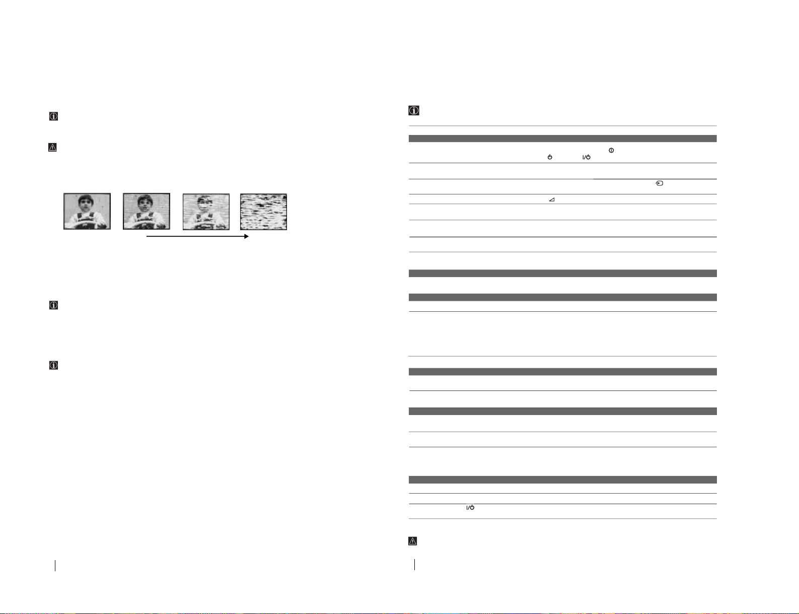
Even the Auto Head Cleaner built into this set automatically cleans the video heads when a cassette is loaded or
unloaded. However, if the playback pictures are noisy and hardly visible or no picture appears, video heads
probably need an extra cleaning. In this case, clean the video heads using the V-25CL video head cleaning tape (not
supplied) or ask Sony service personnel to clean the video heads.
Do not use a commercially available wet-type cleaning tape, as it may damage the video heads.
Symptoms caused by contaminated video heads
Worn Video heads
If your Video TV displays a poor picture after you clean the video heads, you may need to replace them. Consult
your dealer or the Sony Service Centre nearest you.
Check the video heads after 1,000 hours of use
A Video TV is a high precision machine. It must record on or play from magnetic tapes on which the image signals
from the colour TV or the video camcorder are recorded.
The video heads or mechanical parts for transporting the tape are contaminated or worn after extended use. You
should have your Video TV checked after each 1,000 hours of use.
Additional Information
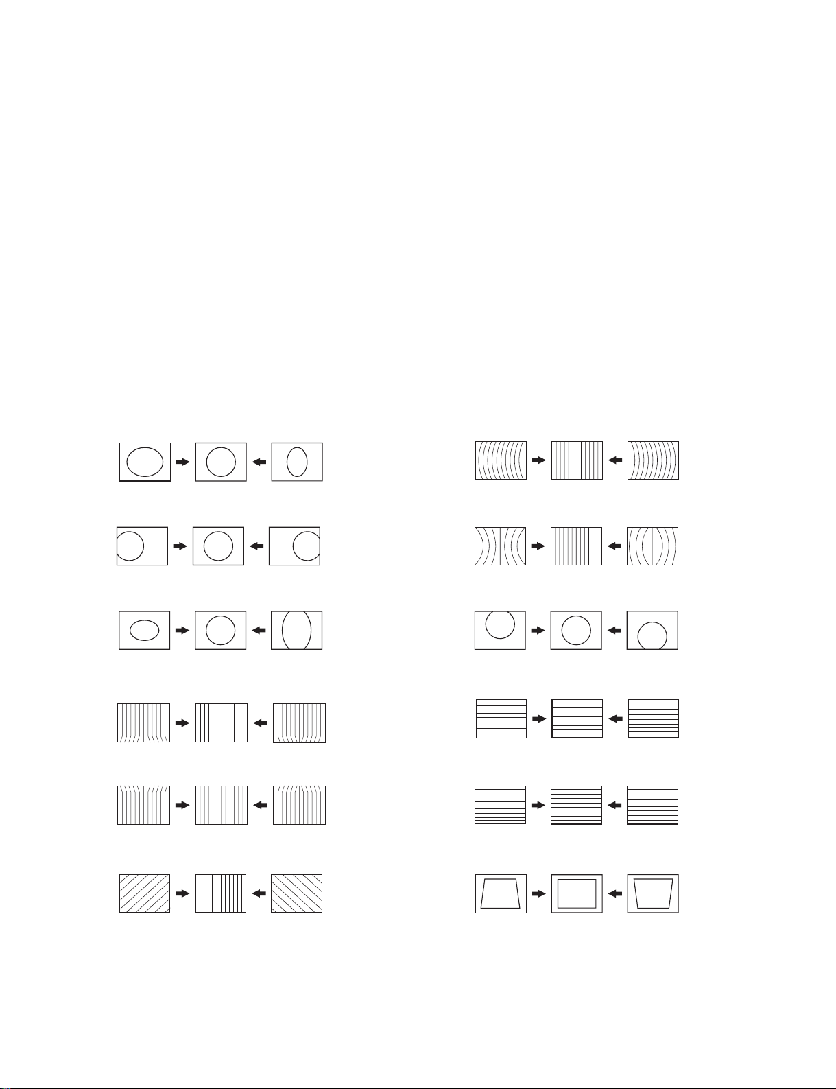
• Normal picture • Rough picture • Unclear picture • No picture (or black& white
screen appears)
initial
terminal
22
Additional Information
Solution
• Check the aerial connection.
• Plug the Video TV in and press the button on the front of TV or if the standby
indicator is on, press button.
• Using the menu system, select the “Picture Adjustment” menu and select “Reset”
to return to the factory settings.
• Check that the optional equipment is on and press the button repeatedly on
the remote control until the correct input symbol is displayed on the screen.
• Press the +/- button on the remote control.
• Using the menu system, select the “Picture Adjustment” menu and select “Reset”
to return to factory settings.
• Turn off any equipment connected to the Scart connector on the rear of the
TV.
• Using the menu system, select the “Picture Rotation” option in the “Set Up” menu
to correct the picture slant.
• Using the menu system, select the “Manual Programme Preset” menu and adjust
Fine Tuning (AFT) to obtain better picture reception.
• Reset the clock and timer settings. for details refer to the section “Setting the Clock
Manually” (see page 7).
• Switch off, disconnect the AC power cord and leave the set for about one minute.
• Using the menu system, select the “VCR Set Up” menu and check the “Colour
System” option.
• Adjust the tracking manually. For details refer to the section “Adjusting the
Tracking” (see page 16).
• Clean the video heads. For details refer to the section ”Video Head Cleaning” (see
page 20).
• Use a new tape.
• Use a new tape.
• Cover the safety tab hole. For details refer to the section “ “Protecting your
cassette against accidental erasure” (see page 10).
• Insert a cassette with its safety tab intact.
• Rewind the tape.
• Set the current time and date. For details refer to the section “Setting Clock
Manually” (see page 7).
• Cover the safety tab hole. For details refer to the section “ “Protecting your
cassette against accidental erasure” (see page 10).
• Insert a cassette with its safety tab intact.
• Rewind the tape.
• Check the settings for timer recording. For details refer to the section “Checking/
Adding/Changing/Cancelling the Timer Settings” (see page 15).
• Press EJECT 6 to eject the cassette that it is already inserted.
• Replace the batteries.
• Contact to your nearest Sony service centre.
In case of problems, have your TV serviced by qualified personnel. Never open the casing yourself.
Troubleshooting
If you have any problems while viewing your Video TV, please check the following troubleshooting guide. If the problem
persists, contact your Sony dealer.
Problem
TV Section
No picture (screen is dark) and no
sound.
Poor or no picture (screen is dark), but
good sound.
No picture when watching equipment
connected to the Scart connector.
Good picture, no sound.
No colour on colour programmes.
Distorted picture when changing
programmes or selecting teletext.
Picture slanted (only for KV-21FV1U).
Noisy picture when viewing a TV
channel.
Clock section
The clock has stopped and “--:--“ is
displayed.
Playback section
Power is on, but the tape does not run.
Poor playback picture.
The sound drops out.
Recording section
The cassette is ejected when you press
REC r .
Cannot record.
Timer recording section
Cannot program a recording using the
timer.
The cassette is ejected when you press
TIMER REC ON/OFF.
The TIMER REC indicator on the front
of the Video TV does not light up even
though you press TIMER REC ON/
OFF.
Others
A cassette cannot be inserted.
Remote control does not function.
The standby indicator on the Video
TV flashes.
– 15 –
SECTION 2
DISASSEMBLY
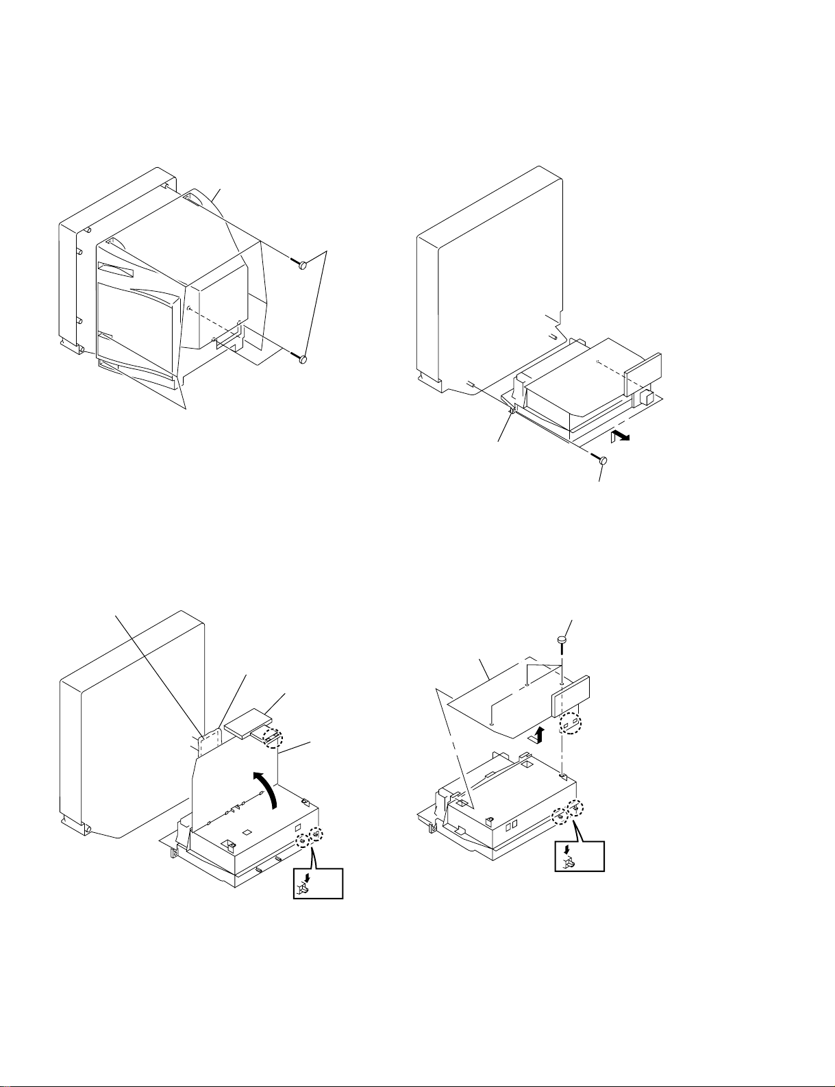
2-1. REAR COVER REMOVAL 2-2. CHASSIS ASSY REMOVAL
2
Rear cover
1
Eight screws
(+BVTP 4 X 16)
2
Chassis assy
Two screws (+BVTP 4 X 16)
1
2-3. SERVICE POSITION (A BOARD) 2-4. A BOARD REMOVAL
CV board
Insulator
Terminal board
A board
3
A board
1
(+BVTP 3 X 12)
Three screws
Claw
Claw
Note: Open the A board after slide the terminal board
– 16 –
2
Two
Claws
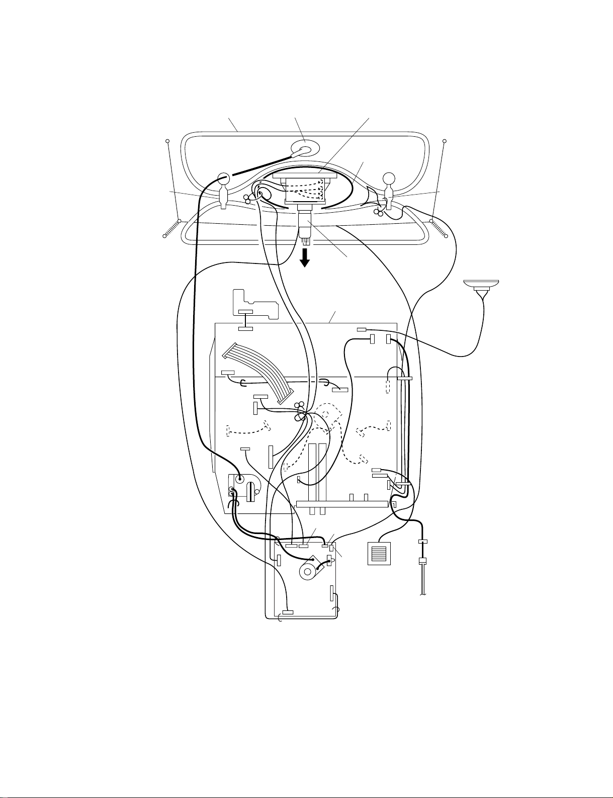
2-5. HARNESS LOCATION
DGC holder
Demagnetic coil
H10 board
CN002
CN001
CN1003
CN305
CN306
CN1002
CN1301
CVM board
MA10 board
CN301
CN302
Deflection yokeAnode cap
NA rotation coil
DGC holder
VM coil
Speaker
CN251
CN1703
CN1701
CN1702
CN803
CN801
FBT
CN401
CN604
CN1705
CN1801
CVM
board
CN1703
CN707
CN701
A
board
CN706
CN606
CN603
CN601
CN702
Choke coil
(21inches model only)
C703
CN1001
Power cord
– 17 –
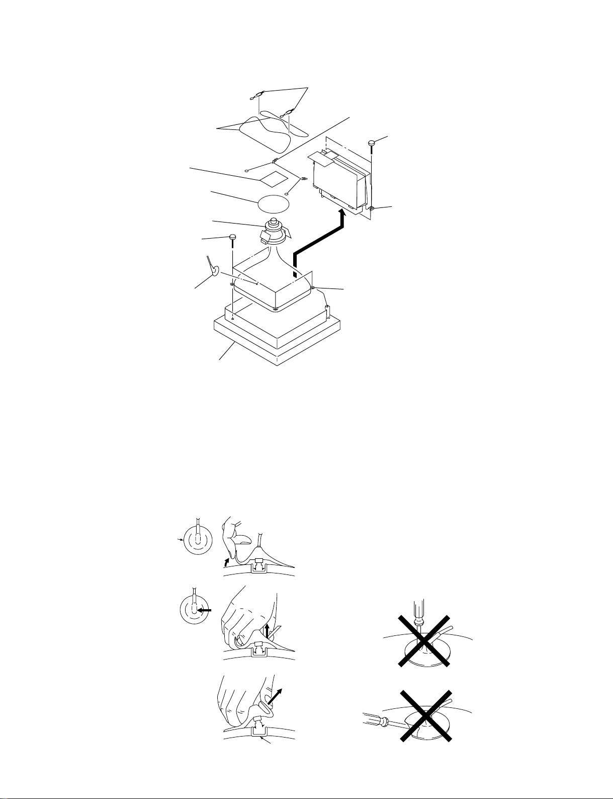
2-6. PICTURE TUBE REMO VAL
8Demagnetization
4 CV board
5 NA rotation coil
6 Deflection yoke
0 Four screws
(Tapping screw 5)
7Two DGC clips
9Two spring
2 Two screws (+BVTP 4 X 16)
3 Chassis assmbly
1 Anode cap
Cushion
• Removal of anode-cap
NOTE : Short circuit the anode of the picture tube and the
anode cap to the metal chassis, CRT shield or carbon paint on the CRT, after removing the anode.
• removing procedures
1 Turn up one side of the
rubber cap in the
direction indicated by
the arrow a.
a
a
!¡ Picture tube
• how to handle an anode-cap
1 Don't hurt the surface of anode-caps with shaped
objects!
2 Don't press the rubber too hard so as not to hurt inside of
anode-caps!
A metal fitting called the shatter-hook terminal is built into
the rebber.
3 Don't turn the foot of rubber over too hard!
The shatter-hook terminal will stick out of damage the
rubber.
2 Using a thumb pull up the
rubber cap firmly in the
direction indicated by the
arrow b.
3 When one side of the rubber
cap is separated from the
anode button, the anode-cap
can be removed by turning
up the rubber cap and pulling
it up in the direction of the
arrow c.
b
b
c
– 18 –
SECTION 3
SET-UP ADJUSTMENTS
• The following adjustments should be made when a complete
realignment is required or a new picture tube is installed.
• These adjustments should be performed with the rated
power supply voltage, unless otherwise noted.
The PICTURE and Brightness controls should be set as follows
unless otherwise noted:
CONTRAST.......................... 100% (LIVE)
BRIGHTNESS control.......... 50%
COLOUR .............................. 50%
HUE ....................................... 50%
SHARPNESS ........................ 50%
Preparation:
• In order to reduce the influence of external magnetic
forces on the picture tube, face the TV set in an easterly
or westerly direction.
• Turn the power switch for the unit ON and erase the magnetic
force using a degausser.
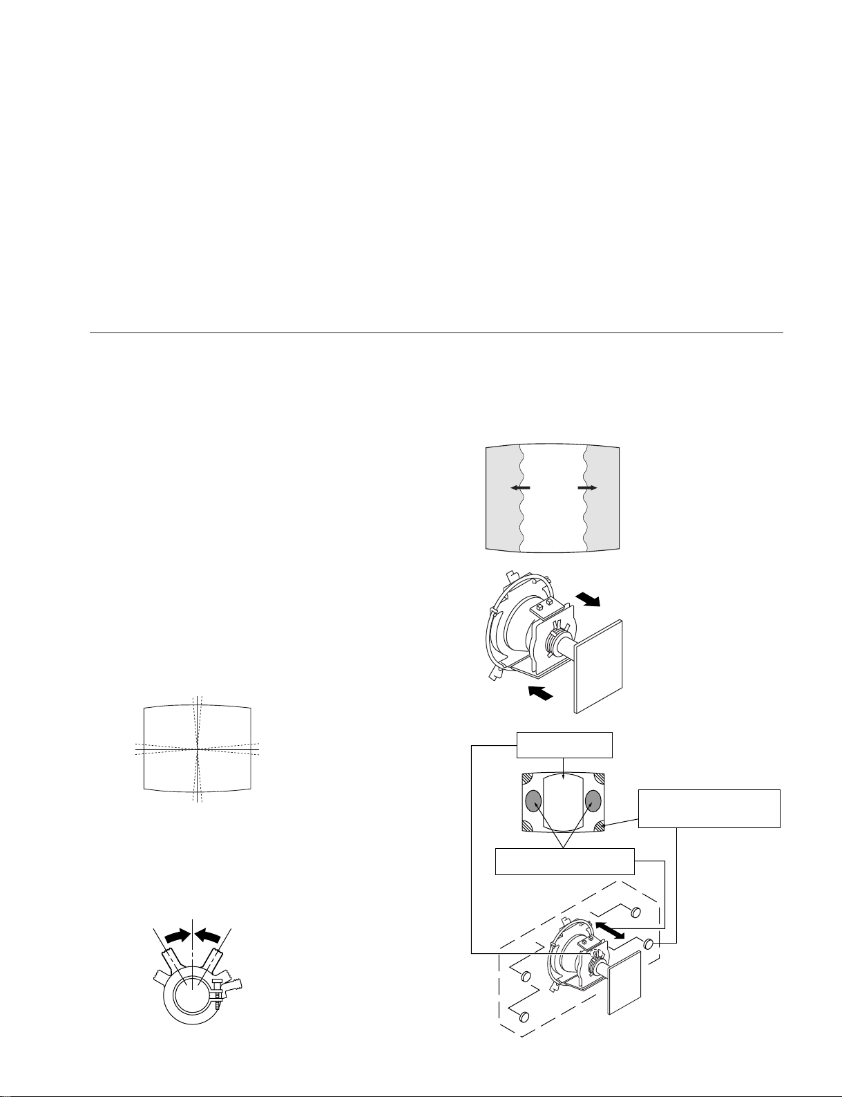
3-1. BEAM LANDING
1. Degauss CRT screen.
2. Inut all-green pattern.
3. Adjust roughly landing at the centre of the screen by moving
the purity magnet.
4. Adjust toughly landing at both right and left sides of the screen
by sliding the DY forward or backward.
5. Adjust landing according to the lupe method or the allowance
mothod.
6. Adjust DY so the horizontal tilt of DY is within the standard.
Product standard is as follows.
± 1°
Perform the adjustments in the following order:
1. Beam Landing
2. Convergence
3. Focus
4. Screen (G2)
5. White Balance
6. Picture Distortion
Note: Test Equipment Required.
1. Color bar/Pattern Generator
2. Degausser
3. Oscilloscope
BGR
Fig.3-2
Fig.3-3
± 1°
7. Use disk magnet, if landing at the corner is not good.
Disk mg shold be applyied on the funnel. Don't use mag if
possible because of picture distortion.
8. Screw down the DY.
Purity control
Fig.3-1
– 19 –
Purity control
corrects this area.
ab
cd
Deflection yoke positioning
corrects these areas.
b
d
Disk magnets or rotatable
disk magnets correct these
areas (a-d).
a
c
Fig.3-4
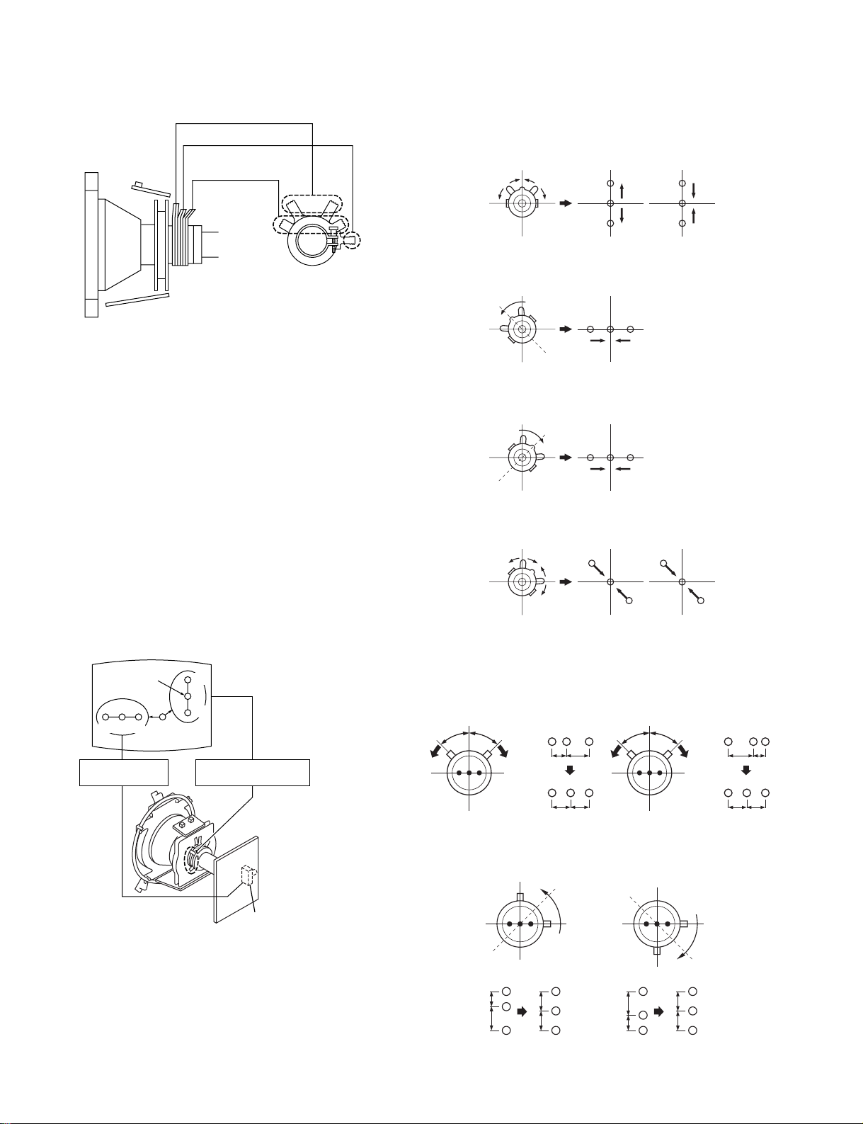
3-2. CONVERGENCE
B
G
R
B
G
R
BGR
BGR
B
G
R
B
G
R
1 Movement of opening or closing the
V. STAT convergence magnet.
2 Movement of tilting the V. STAT conver-
gence magnet counterclockwise.
3 Movement of tilting the V. STAT conver-
gence magnet clockwise.
4 Movement of tilting and opening or clos-
ing the V. STAT convergence magnet.
Purity
BMC magnet
Vertical static
convergence magnet
(1) Horizontal and Ver tical Static Convergence
1. Receive the channel with dot signal.
2. Minimize BRT and set picture level to the position where the
dot is easy to see.
3. Adjust horizontal convergence at the centre of the screen with
V. STAT correction piece.
4. Adjust vertical convergence of dot at the centre of the screen
with V. STAT MG.
5. Adjust repeatedly static convergence according to righe figure
in case that both HMC and VMC are not independant.
In case of both HMC and VMC exist attach BMC magnet to
neck assembly.
Case of HMC attached
Turn BMC over in case of adjustment in opposite direction.
Use BMC mg only when it is necessary, for it mak es CR T focus
worse.
Center dot
R
G
B
Horizontal static
convergence
R
G
B
Vertical static
convergence magnet
• Movement of red, green and blue dots by V. ST A T tilting
and opening or closing.
• If the blue dot did not harmonize with red and green,
then use the BMC magnet to adjust.
1)HMC (Horizontal mis-convergence) correction
HMC correction (A)
R
GB
A <
B
AB
RGB
A =
B
AB
HMC correction (B)
R
GB
A >
B
AB
RGB
B
A =
AB
RV702 (H-STAT)
Fig.3-5
– 20 –
2)VMC (Vertical mis-convergence) correction.
VMC correction (A) VMC correction (B)
C < D C = D C > D C = D
R
C
G
D
B
R
C
G
D
B
RR
C
D
C
G
D
B
G
B
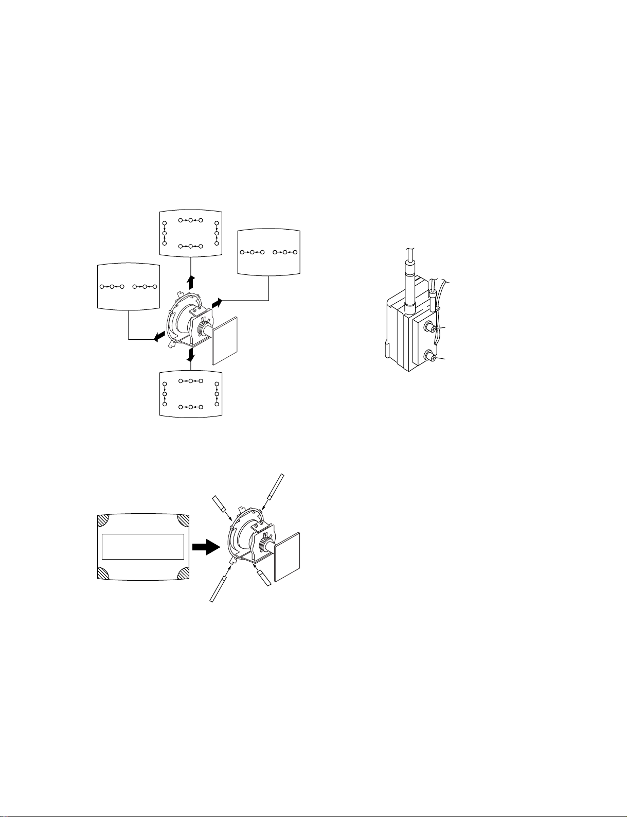
(2) Convergence adjustment of screen surroundings.
(Dynamic convergence)
1. Recieve dot pattern.
2. Set BRT to main and PIC to the level where dot pattern is
easy to see.
3. Shake DY up and down. Insert DY spacer at position 'A' so
that cross MIS convergence is minimum.
4. Shake DY right or left and insert DY spacer at position 'C'
and 'D' where tilt is the smallest both on vertical and
horizontal axis.
R
G
B
B
G
R
B
G
B
R
G
R
R
G
BB
G
R
3-3. FOCUS ADJUSTMENT
1. Receive monoscope pattern.
2. Adjust FBT focus VR so that the picture has the best focus.
Adjust the focus so that the center of the screen is in the best
focus.
Turn focus VR clockwise to the end and then tur n back counter
clockwise.
While turning back, pay attention to the centre cross of the
colour pattern, and then adjust the VR so that horizontal line
because clear and vertical line begins to become unclear.
Change signal to dot pattern, confirm that corner focus is good.
3. Receiving white signal, confirm that magenta ring is hardly
noticed.
R
G
a
a-d : screen-corner
misconvergence
c
G
B
B
R
B
R
G
B
R
Fig.3-6
b
d
Fuoco
Schermo
R
B
G
G
R
G
B
3-4. SCREEN (G2) ADJUSTMENT
Fig.3-8
1. Receive a Black signal, Cross and Hatch signal or dots signal.
2. Make sure to be in Personal, reset condition.
3. Adjust screen VR on FBT so that highest level of black area
among kathodes is 175 ± 2 V.
a
b
Fig.3-7
d
c
– 21 –
3-5. WHITE BALANCE ADJUSTMENT
1. Input ehite pattern. Adjust white balance of drive side, using
service mode VP No. 22 RAMP, No. 23 GAMP and No. 24
BAMP, so that colour temperature is 8600 K + 0 MPCD.
2. Input gray pattern for 10NIT. Adjust white balance of cut-off
side, using service mode No. 25 RCUT, No. 26 GCUT and No.
27 BCUT, so that colour temperature is 8600 K + 0 MPCD.
3. To take tracking, confirm again tha t colour temperatures of both
side are within the limit of the above standard 8600 K + 0
MPCD. If necessary, re-adjust.
W/B Specification:
H/L difference = 2JND or less
C/O difference = 3JND or less
3-6. PICTURE DISTORTION ADJUSTMENT
• When performing these adjustment, do receive monoscope
signal.
VP01 (HSIZ) VP07 (AFBW)
VP02 (HPOS)
VP04 (LCPN)
VP05 (UCPN)
VP06 (AFAG) VP13 (TRAP)
VP08 (PAMP)
VP09 (VPOS)VP03 (VSIZ)
VP10 (VLIN)
VP11 (SCOR)
– 22 –
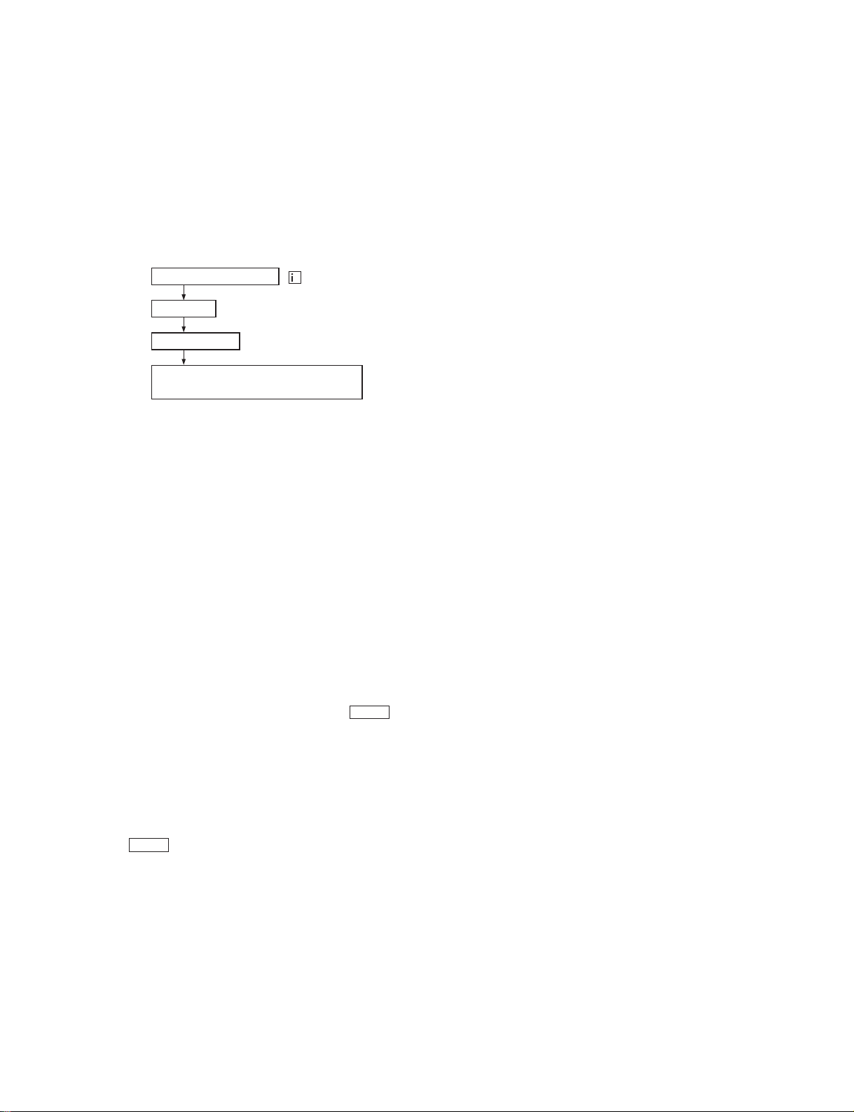
SECTION 4
CIRCUIT ADJUSTMENTS
4-1. ADJUSTMENTS WITH COMMANDER
1. ENTERING SERVICE MODE
1) Turn on the main power of the set and enter into stand-by
mode.
2) Press the following sequence of buttons on the Remote
Control Commander.
ON SCREEN DISPLAY
CH “ 5 ”
VOLUME (+)
POWER “ ON ”
(REMOTE CONTROL POWER “ ON ”)
2. TO READ THE MEMORY
1) Set to service mode.
2) When push these buttons 7 n - on the remote
commander, it would read all item's adjustment value and
switch set-up value which written in the memory.
Note: Do not read before "standard value" writing when exchange
the MEMORY IC002.
+
u
6. WRITING "STAND ARD V ALUE"
1) Set to service mode.
2) When push 5 button on the remote commander green
colored "INITIAL write" indicates on the screen right above.
Continuing to press - button while words are displaying
(about 3 seconds). Display turns to red colored "INITIAL
write" then the screen become pitch-dark and select 1ch
about 5 seconds after. Then it turns green colored "G"
display.
Perform writing "standard value" standard data in micro
computer will write to the MEMORY and set to initialization
state all.
Note: When exchange only MEMORY IC002, perform "standard
value" writing in the begginning.
3. PICTURE ADJUSTMENT
1) Select adjustment item number of service mode by 1 and
4 buttons on the remote commander.
2) Adjust 3 and 6 buttons to satisfy set-up v alue and picture
condition of the screen.
4. WRITE T O THE MEMORY
• After adjusted, write to the MEMORY by MUTE and buttons and push - button while green "light" word
indicated on the picture display (about 3 seconds). It takes
about 1 second to complete the writing to the MEMORY.
When red "light" displayed turns to "G" and that makes
writing completely finish.
Color of the screen displayed light word.
MUTE button on..................... Green word
- button on ........................... Red word
5. RELEASE THE SERVICE MODE
• Turn off TV set and turn on again or turn of f by the r emote
commander, and turn off by the remote commander again
by stand-by state to disappear serivce display and set to
normal TV mode.
– 23 –
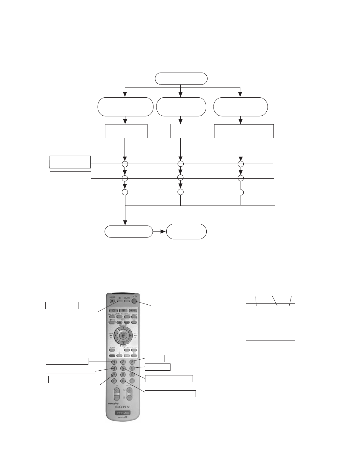
4-2. ADJUSTMENT METHOD
Service adjustment to this model can be performed with the supplied Remote Control Commander RM-955, 956.
• HOW TO ENTER INTO SERVICE MODE
Entering the
service mode
When exchange
the MEMORY
IC002 (MA10 board)
Perform “standard
value” writing
YCJ adjustment
Deflection circuit
adjustment
Micro computer
adjustment
Write to
the MEMORY
Note : • Write to the MEMORY every performing one item adjustment.
• Before writing to the MEMORY adjusted data would not memorize when turn off.
• REMOTE COMMANDER'S FUNCTION IN
SERVICE MODE
When exchange
the board
A board
Release the
service mode.
• SERVICE MODE DISPLAY
When repair connected with picture quality
A board deflection system
exchange CRT and DY.
No.
DATA
SERVICE
ITEM
Write memory
After pressed "0" button
Adjustment item up
Adjustment item down
Read memory
After pressed "0" button
Releace service mode
Data up
Data down
Write standard value
After pressed "0" button
Perform read and write
– 24 –
VP00 VPOS 000 SERVI
21 D05 VPS NS
4-3. SERVICE DATA
No. DISP DATA STANDARD ITEM DEVICE
VP00 SBRT 00-3F 17 SUB BRIGHT CXA2139S
VP01 HSIZ 00-3F 27 H SIZE (Y/C/J)
VP02 HPOS 00-3F 1B H POSITION
VP03 VSIZ 00-3F 1D V SIZE
VP04 LCPN 00-3F IE LOWERSIDE CORNER PIN
VP05 UCPN 00-3F 17 UPPERSIDE CORNER PIN
VP06 AFAG 00-0F 07 AFC ANGLE
VP07 AFBW 00-0F 07 AFC BOW
VP08 PAMP 00-3F 0C PIN AMPLITUDE
VP09 VPOS 00-3F 22 V POSITION
VP10 VLIN 00-0F 07 V LINEARITY
VP11 SCOR 00-0F 07 S CORRECTION
VP12 AFC 00-03 01 AFC LOOP GAIN SWITCHING
VP13 TRAP 00-0F 06 TRAPEZIUM
VP14 HBLK 00-01 00 H BLANKING
VP15 LBLK 00-0F 07 LEFT H BLANKING
VP16 RBLK 00-0F 07 RIGHT H BLANKING
VP17 VUND 00-01 00 V UNDER SCAN
VP18 EHT 00-0F 07 EHT COMP
VP19 HSS 00-01 00 SLICE LEVEL OF H SYNC SEPARATION
VP20 VSS 00-01 00 SLICE LEVEL OF V SYNC SEPARATION
VP21 HMSK 00-01 01 H MASK
VP22 RAMP 00-3F 21 R DRIVE
VP23 GAMP 00-3F 14 G DRIVE
VP24 BAMP 00-3F 0F B DRIVE
VP25 RCUT 00-0F 0F R CUTOFF
VP26 GCUT 00-0F 06 G CUTOFF
VP27 BCUT 00-0F 00 B CUTOFF
VP28 SCOL 00-3F 21 SUB COLOR FOR PAL
VP29 SHUE 00-1F 1F SUB HUE
VP30 SSHP 00-0F 07 SUB SHARPNESS
VP31 SHPF 00-01 00 SHARPNESS F0 SWITCHING
VP32 PREL 00-01 00 PRE/OVER-SHOOT RATIO SWITCHING
VP33 GAMM 00-01 02 GAMMA CORRECTION
VP34 ABLM 00-01 01 ABL MODE
VP35 VTH 00-01 01 ABL VTH
VP36 DYCL 00-01 01 DYNAMIC COLOR
VP37 YDC 00-01 01 DC TRAN
VP38 RON 00-01 01 R ON
VP39 GON 00-01 01 G ON
VP40 BON 00-01 01 B ON
VP41 CDMD 00-03 00 COUNT DOWN MODE
VP42 HOSC 00-0F 07 H VCO’S OSCILLATION
VP43 VMSW 00-01 00 VM SW
VP44 YDE 00-0F 00 Y DELAY
VP45 PAF 00-03 00 PB AFC
VP46 IDS 00-03 02 ID START
VP47 IDP 00-03 02 ID STOP
VP48 IDL 00-03 02 ID LEVEL
VP49 BELL 00-3F 25 BELL F0
VP50 SCSE 00-3F 1F SUB COLOR FOR SECAM
VP51 GDSE 00-0F 07 G DRIVE (SECAM) *DISPLAY -7 to +8*
VP52 BDSE 00-0F 07 B DRIVE (SECAM) *DISPLAY -7 to +8*
VP53 RCSE 00-1F 10 R CUTOFF (SECAM) *DISPLAY -15 to +16*
VP54 GCSE 00-1F 10 G CUTOFF (SECAM) *DISPLAY -15 to +16*
VP55 BCSE 00-1F 10 B CUTOFF (SECAM) *DISPLAY -15 to +16*
VP56 GDLI 00-0F 07 G DRIVE (LIVE) *DISPLAY -7 to +8*
VP57 BDLI 00-0F 07 B DRIVE (LIVE) *DISPLAY -7 to +8*
VP58 RCLI 00-0F 07 R CUTOFF (LIVE) *DISPLAY -7 to +8*
VP59 GCLI 00-0F 07 G CUTOFF (LIVE) *DISPLAY -7 to +8*
VP60 BCLI 00-0F 07 B CUTOFF (LIVE) *DISPLAY -7 to +8*
RANGE DATA
– 25 –
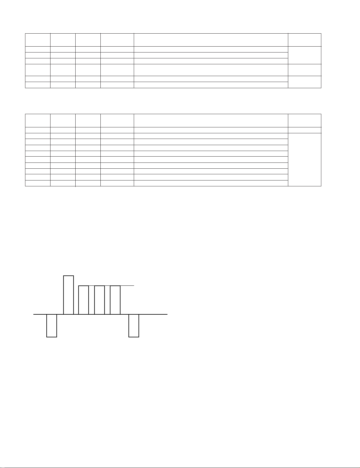
No. DISP DATA STANDARD ITEM DEVICE
IF00 AMFM 00-01 00 AUTO MUTE FM
IF01 GAIN 00-01 00 AUDIO GAIN
IF02 GATE 00-01 00 GATING (POSITIVE MODULATION)
IF03 TOP 00-1F 10 TAKE OVER POINT *DISPLAY -16 to +15* CXP85452
IF04 TAGC 00-1F 10 AGC FOR TV TUNER *DISPLAY -16 to +15*
IF05 VAGC 00-1F 10 AGC FOR VCR TUNER *DISPLAY -16 to +15*
No. DISP DATA STANDARD ITEM DEVICE
OP00 OSDH 00-3F 06 OSD HORIZONTAL POSITION
OP01 NS 00-01 01 NS COIL CXP85452
OP02 LWAI 00-1F 13 L SYSTEM TUNING WAIT TIMER (µ-COM)
OP03 HDCG 00-03 00 HEADCLOG DETECT
OP04 MUT 00-01 01 FTZ MUTE (0:OFF 1:ON)
OP05 VPS 00-01 01 VPS (0:NO EXIST 1:EXIST)
OP06 BDES 00-01 00 B DESTINATION (0:OTHERS 1:B)
OP07 UDES 00-01 00 U DESTINATION (0:OTHERS 1:U)
OP08 ID0 00-01 00 PAINTER M3A/M3C SELECT (0:M3A 1:M3C)
OP09 ID1 00-01 00 NVM-ID1 (RESERVE)
RANGE DATA
(µ-COM)
RANGE DATA
4-4. A BOARD ADJUSTMENT
1. SUB COLOUR ADJUSTMENT
1) Recieve the PAL colour bar signal.
2) Check the pin4 of CN305 by oscilloscope.
3) Adjust the part of the right waveform to become the same
level by service mode (VP28:Sub colour).
Same level
B-Out waveform
Fig.4-1
– 26 –
 Loading...