

Sony KP-XR43KR1, KP-XR43TW1, KP-XR48KR1, KP-XR53KR1, KP-XR53TW1 Service Manual
SERVICE MANUAL
RA-3A
CHASSIS
MODEL COMMANDER DEST. CHASSIS NO.
–––––– –––––––––––– ––––– –––––––––––
KP-XR43KR1 RM-Y906K Korean SCC-P50A-A
KP-XR43TW1 RM-Y906 Taiwan SCC-P51A-A
KP-XR48KR1 RM-Y906K Korean SCC-P50C-A
KP-XR53KR1 RM-Y906K Korean SCC-P50B-A
KP-XR53TW1 RM-Y906 Taiwan SCC-P51B-A
MODEL COMMANDER DEST. CHASSIS NO.
–––––– –––––––––––– ––––– –––––––––––
DVD/
POWER
MUTING
SAT/
VTR
CABLE
TV
FUNCTION
SYSTEM
OFF
TV
DVD/VTR SAT/CABLE
TV/VTR
FREEZE
SWAP PIP
m
N
M
AUDIO
POSITION ACTIVE
X
xz
ANT
TV/VIDEO
SLEEP
PICTURE
CC
MODE
DISPLAYMTS/SAP
2
1
3
5
6
4
7
9
8
JUMP
ENTER
0
INDEX
GUIDE
RESET
MENU
VOL CH
CODE SET
TV
RM-Y906/Y906K
KP-XR43KR1/XR43TW1 KP-XR48KR1/XR53KR1/XR53TW1
∗ Please file according to model size. .......
43
48 53
PROJECTION TV

KP-XR43KR1/XR43TW1/XR48KR1/XR53KR1/XR53TW1
RM-Y906K RM-Y906 RM-Y906K RM-Y906K RM-Y906
SPECIFICATIONS
Projection system
3 picture tubes, 3 lenses, horizontal in-line
system
Picture tube
7-inch high-brightness monochrome tubes (6.3 raster size),
with optical coupling and liquid cooling system
Projection lenses
High performance, large diameter hybrid lens F1.05
Television system
American TV standard
Channel coverage
VHF: 2–13/UHF: 14 –69/CATV: 1 – 125
Antenna
75 ohm external terminal for VHF/UHF
Screen size (measured diagonally)
43 inches (KP-XR43KR1/XR43TW1)
48 inches (KP-XR48KR1)
53 inches (KP-XR53KR1/XR53TW1)
Inputs/outputs
VIDEO 1 IN
VIDEO 2 INPUT
S VIDEO IN (4-pin mini DIN):
Y: 1 Vp-p, 75-ohms unbalanced, sync negative
C: 0.286 Vp-p (Burst signal), 75 ohms
VIDEO (phono jack): 1 Vp-p, 75-ohms unbalanced, sync
negative
AUDIO (phono jacks): 500 mVrms (100% modulation),
Impedance: 47 kilohms
VIDEO 3 IN
S VIDEO IN (4-pin mini DIN):
Y: 1 Vp-p, 75-ohms unbalanced, sync negative
C: 0.286 Vp-p (Burst signal), 75 ohms
VIDEO (phono jack): 1 Vp-p, 75-ohms unbalanced, sync
negative
Y: 1 Vp-p, 75 ohms, sync negative
PB : 0.7 Vp-p, 75 ohms
PR : 0.7 Vp-p, 75 ohms
AUDIO (phono jacks): 500 mVrms (100% modulation),
Impedance: 47 kilohms
MONITOR OUT
VIDEO (phono jack): 1 Vp-p, 75-ohms unbalanced, sync
negative
AUDIO (phono jacks): 500 mVrms (100% modulation),
Impedance: 470 ohms
AUDIO (VAR/FIX) OUT (phono jacks): 500 mVrms (100%
modulation), Impedance: 470 ohms
CONTROL S OUT: minijack
Speaker
Tweeter: 66 mm (2 5 /8 ”) x 2 (KP-XR48KR1/XR53KR1/
XR53TW1)
Woofer: 130 mm ( 17 /32 ”)x 2 (KP-XR48KR1/XR53KR1/
XR53TW1)
100 mm (4”) x 2 (KP-XR43KR1/XR43TW1)
Speaker output
15W x 2
Power requirement
110 V AC, 60 Hz (KP-XR43TW1/XR48TW1/XR53TW1)
220 V AC, 60 Hz (KP-XR43KR1/XR53KR1)
Power consumption
In use (Max.): 160 W
In standby: 1 W
Dimensions (W/H/D)
966 x 1,063 x 508 mm (38 1 /8 x 41 7 /8 x 20 inches)
(KP-XR43KR1/XR43TW1)
1,091 x 1,337 x 588 mm (43 x 52 3 /4 x 23 1 /4 inches)
(KP-XR48KR1)
1,218 x 1,423 x 618 mm (48 x 56 1 /8 x 24 3 /8 inches)
(KP-XR53KR1/XR53TW1)
Mass
61.5 kg (135 lbs 9 oz) (KP-XR43KR1/XR43TW1)
65 kg (143 lbs 5 oz) (KP-XR48KR1)
69.5 kg (153 lbs 4 oz) (KP-XR53KR1/XR53TW1)
Supplied accessories
Remote control RM-Y906K (1) (KP-XR43KR1/XR48KR1/
XR53KR1), RM-Y906 (KP-XR43TW1/XR53TW1)
Batteries (2) size AA (R6)
Design and specifications are subject to change without
notice.
– 2 –
KP-XR43KR1/XR43TW1/XR48KR1/XR53KR1/XR53TW1
RM-Y906K RM-Y906 RM-Y906K RM-Y906K RM-Y906
SELF DIAGNOSIS FUNCTION
1. Summary of Self-Diagnosis Function
• This device includes a self-diagnosis function.
• In case of abnormalities, the TIMER/STANDBY indicator automatically blinks. It is possible to predict the abnormality location
by the number of blinks. The Instruction Manual describes blinking of the TIMER/STANDBY indicator.
• If the symptom is not reproduced sometimes in case of a malfunction, there is recording of whether a malfunction was generated
or not. Operate the remote command to confirm the matter on the screen and to predict the location of the abnormality.
2. Diagnosis Items and Prediction of Malfunction Location
• When a malfunction occurs the TIMER/STANDBY indicator only blinks for one of the following diagnosis items. In case of two
or more malfunctions, the item which first occurred blinks. If the malfunctions occurred simultaneously, the item with the lower
blink count blinks first.
• The screen display displays the results regarding all the diagnosis items listed below. The display “ 0 ” means that no malfunc-
tions occurred.
metisisongaiD
NOtonrewoP•0
noitcetedPCOB+semit2.tiucrichcaenimetsysylppusrewopfotiucrictrohS
noitcetedPVOB+semit3.nepo276R
potsnoitcelfedlacitreVsemit4
noitcetedytilamronbatuooediVsemit5
potsnoitcelfedlatnoziroHsemit6
noitcetedytilamronbaoiduAsemit8
* : 000 the range of values for number of operations is 000-255. For 256 or higher there is
no count up and the number remains at 255.
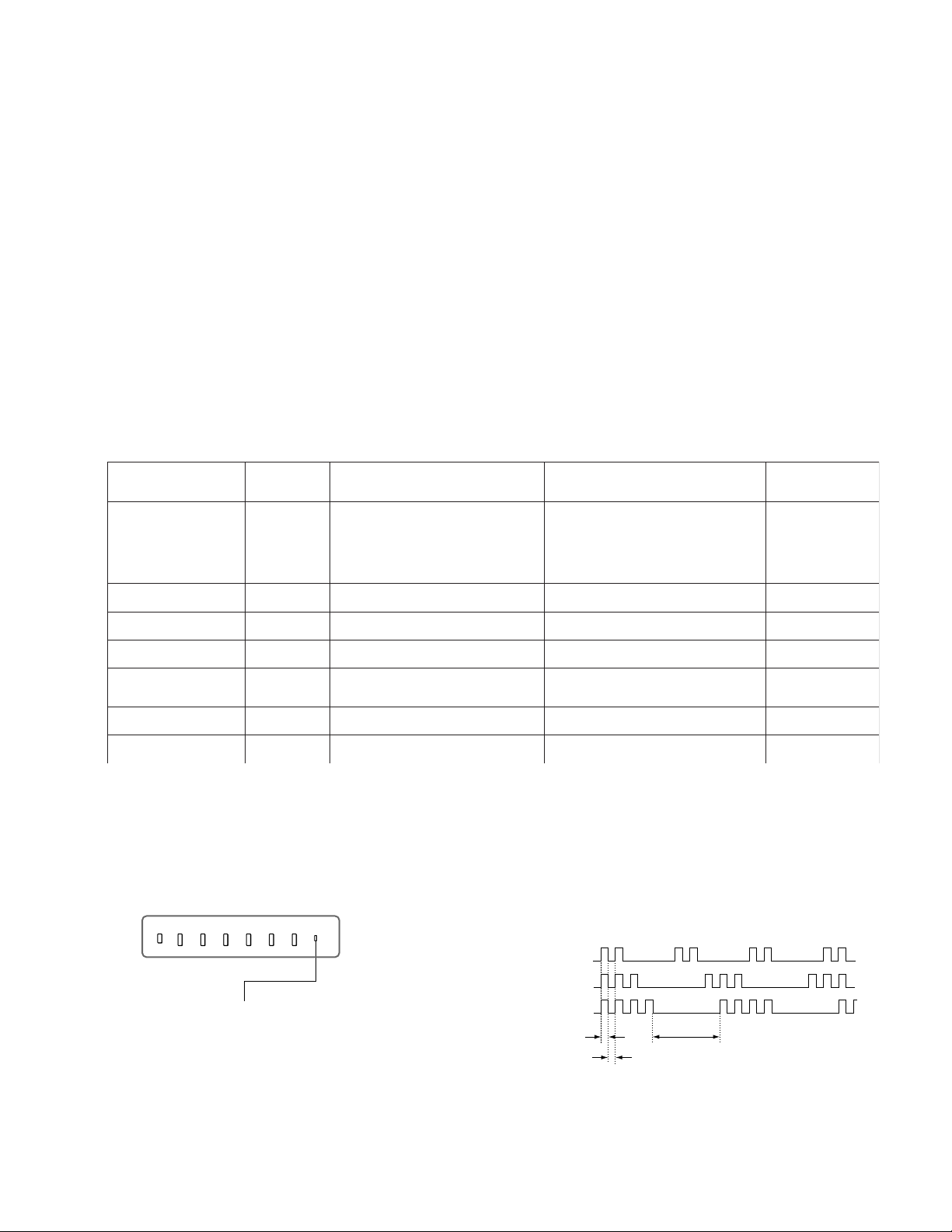
3. Blinking count display of TIMER/STANDBY indicator
YBDNATS/REMIT
retacidnI
sknilbforebmuN
noitcnuflamdesoppuSnoitidnoC
)draobBF(.nepo1006F
.nepo5656R
tiucrictrohs6056Q
]metsySylppuSrewoPniaM[
.nekorbera4156Rdna1056CI
)draobBF(tiucric-trohs1006DV
.nekorbsi)tuoV(9051CI
.tiucricsdraobBCdna
)draobA(022,912,812Q
.nepo615,515C
.nekorbsi)elgnuJCY(602CI
.nekorbsi).pmaoiduA(604CI
.nepo204,104SP
]metsySylppuSrewoPybdnatS[
.rewopehtnonruttonnaC
.knilbt'nseodDEL
edomybdnatsehtotseoG
enilB+fotiucrictrohS
edomybdnatsehtotseoG
tiucricylppusrewopfonoitcnuflaM
.nekorbsi)reffuBesluPV(5051Q
GC,RCnisrehtodna167,237,507Q,tuooediV
.detumsilangis
.sisongaidflesehtrofsknilbnehtdna
.raeppat'nseodretsaR000potSH:6
.tuotonsidnuosehT
edomybdnatsehtotseoG
oedivnehtdnaA,yllatnozirohenilenootseogretsaR
,sdnoces03.xorppasknilbDELYBDNATS/REMIT
sisongaid-fleS
,yalpsidneercs
stluseR:metisisongaiD
000PCOB+:2
000PVOB+:3
000potSV:4
000BKA:5
000oiduA:8
* One blink is not used for self-diagnosis.
< FRONT PANEL >
VOLUME
–+CHANNEL–+
TV/VIDEO
FLASH FOCUS
POWER
•EXAMPLE
TIMER/STAND BY
<Diagnosis Items> <Number of Blinks>
• +B overcurrent 2 times
• +B overvoltage 3 times
TIMER/STANDBY indicator
• Vertical deflection stop 4 times
Lamp ON : 0.3 seconds
Lamp OFF : 0.3 seconds
Lamp OFF :
3.0 seconds
Release of TIMER/STANDBY indicator blinking.
• The TIMER/STANDBY indicator blinking display is released by turning OFF the power switch
on the TV main unit or removing the plug from the power.
– 3 –
KP-XR43KR1/XR43TW1/XR48KR1/XR53KR1/XR53TW1
RM-Y906K RM-Y906 RM-Y906K RM-Y906K RM-Y906
4. Self-diagnosis screen displays
• In cases of malfunctions where it is not possible to determine the symptom such as when the power goes off occasionally or when
the screen disappears occasionally, there is a screen display on whether the malfunction occurred or not in the past (and whether
the detection circuit operated or not) in order to allow confirmation.
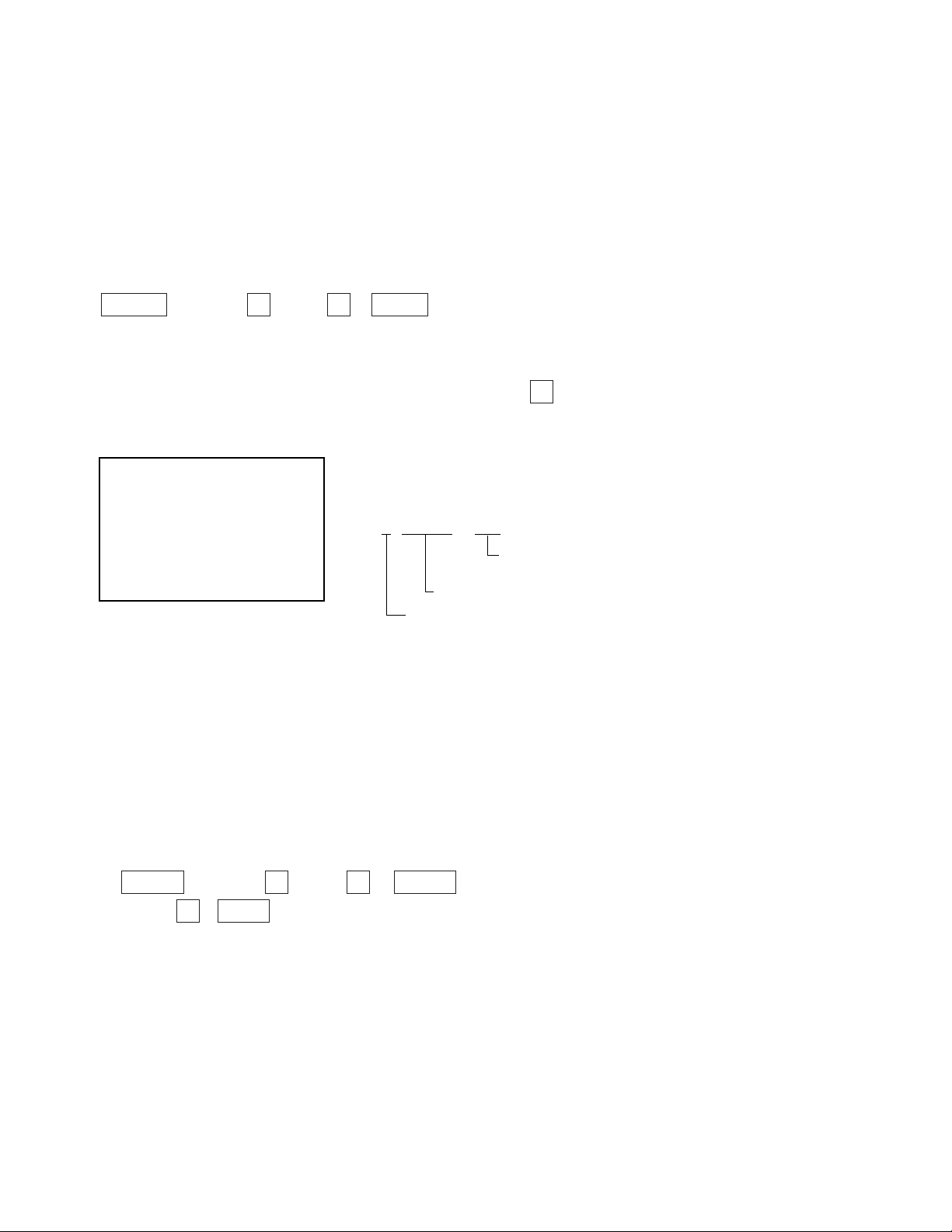
<Screen Display Method>
• Quickly press the remote command button in the following order from the standby state.
DISPLAY b Channel 5 b VOL – b POWER
˘
Be aware that this differs from the method of
entering the service mode (volume + ).
Self-diagnosis screen display
Self Check
2 : +B OCP 000
3 : +B OVP 000
4 : V Stop 000
5 : AKB 000
6 : H Stop 000
7 : HV 000
8 : Audio 000
101 : WDT 000
÷
2 : +B OCP 000
Diagnosis
Results
000 the range of values for number of
operations is 000-255.
For 256 or higher there is no count up
and the number remains at 255.
5. Self-Diagnosis Screen Display
• The results display is not automatically cleared. In case of repairs and after repairs, check the self-diagnosis screen and be sure
to return the results display to “ 0 ”.
• If the results display is not returned to “ 0 ” it will not be possible to judge a new malfunction after completing repairs.
<Method of Clearing Results Display>
1. Power off (Set to the standby mode)
2. DISPLAY b Channel 5 b VOL + b POWER (Service Mode)
3. Channel 8 b ENTER (Test reset = Factory preset condition)
<Method of Ending Self Diagnosis Screen>
• When ending the self-diagnosis screen completely, turn the power switch OFF on the remote commander or the main unit.
– 4 –
KP-XR43KR1/XR43TW1/XR48KR1/XR53KR1/XR53TW1
RM-Y906K RM-Y906 RM-Y906K RM-Y906K RM-Y906
6. Self-diagnosis function operation
OCP Low B and +B line detect DET SHORT, and shut-down POWER ON RELAY.
Reset by turning power on/off.
In case of +B is loaded approx. 1.3A or more, microcomputer detects it via IC651.
OVP In case of +B becomes approx. 150V or more, POWER ON RELAY shuts down and microcomputer detects it via IC651.
Reset by turning power on/off just the same as OCP.
V Stop In case of microcomputer detects 2 seconds or more interval of V Pulse, Reference Pulse turns off by turning off the picture
signal in YC Jungle IC (IC206).
After the picture signal turns off, V Pulse is regenerated 2 seconds or more, the picture signal turns on.
AKB IK detection. Makes LED blinking in case of microcomputer doesn’t detect IK returns of IC206 CXA2147Q 30 seconds or more.
H Stop In case of HV becomes 33kV or more, IC502 detects it and shut-down H Drive Pulse.
Microcomputer receives H Stop data from IC206 and makes LED blinking.
Audio In case of DC component overlaps the output of Audio Amp., microcomputer detects it and makes LED blinking.
Microcomputer forces to shut down the power.
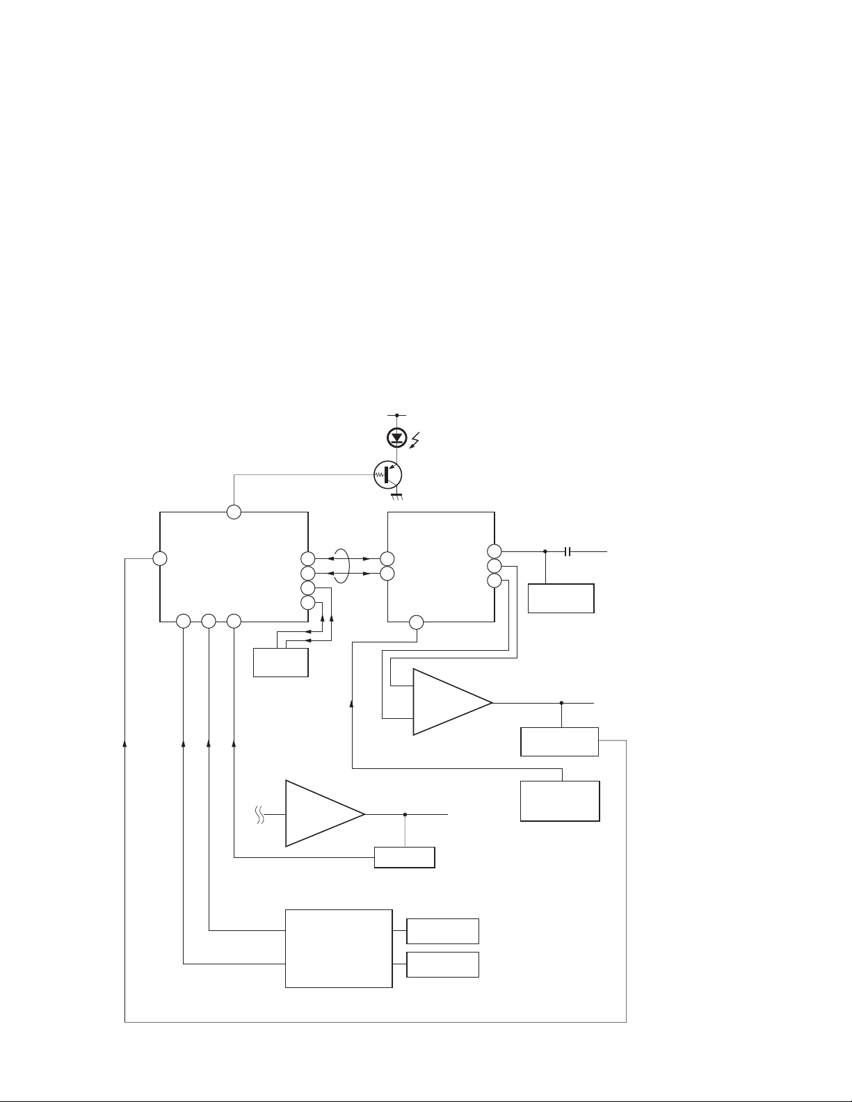
Self-diagnosis block diagram
D1201
TIMER/STANDBY
8
20 21 22
55
IC002
µProcessor
Audio
IC004
EEPROM
Audio AMP
5. AKB
6. H STOP
49
47
50
48
IC406
BUS
5. AKB
Q006
3
4
27
DC Detect
IC206
CXA2147
YCJ
IC1509
V Drive
43
35
34
6. HV STOP
IC502
HV Detector
Q1505
V Pulse Buffer
C Board
4. V.STOP (V Pulse)
3. OVP
2. OCP
IC651
OVP Buffer
OCP Buffer
OVP DETECT
OCP DETECT
– 5 –

KP-XR43KR1/XR43TW1/XR48KR1/XR53KR1/XR53TW1
RM-Y906K RM-Y906 RM-Y906K RM-Y906K RM-Y906
TABLE OF CONTENTS
Section Title Page
–––––– –––– ––––
SELF DIAGNOSIS FUNCTION ............................................ 3
1. GENERAL
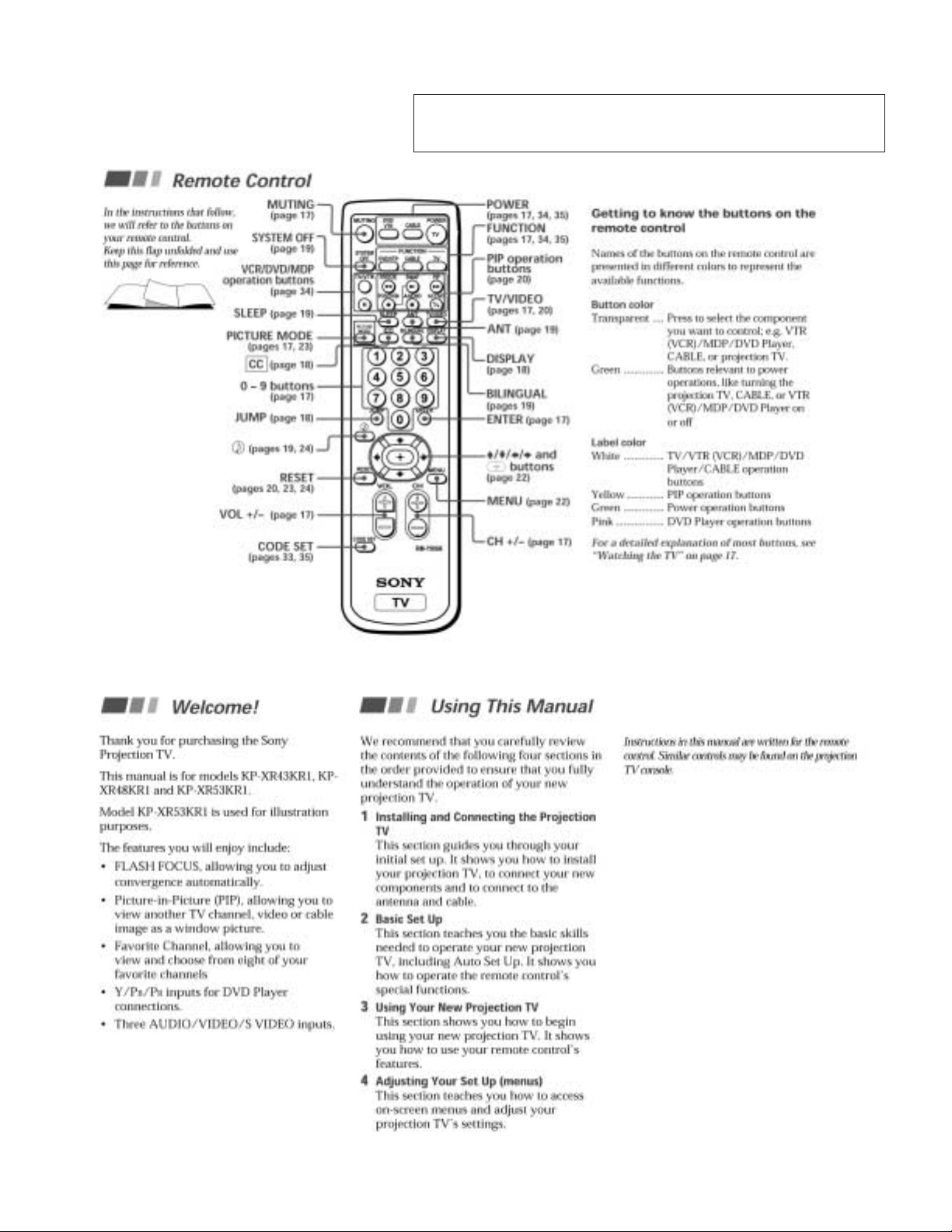
Remote Control ....................................................................... 7
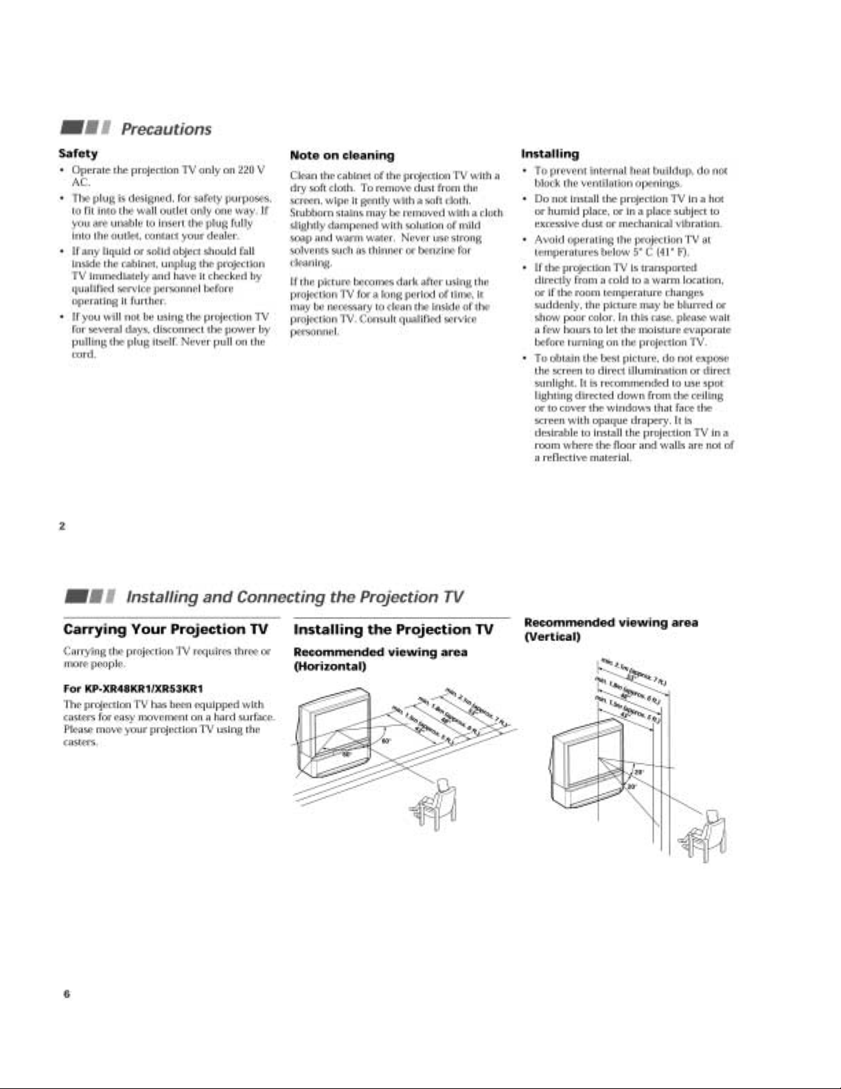
Precautions .............................................................................. 8
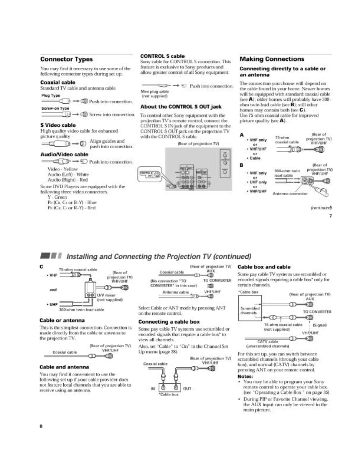
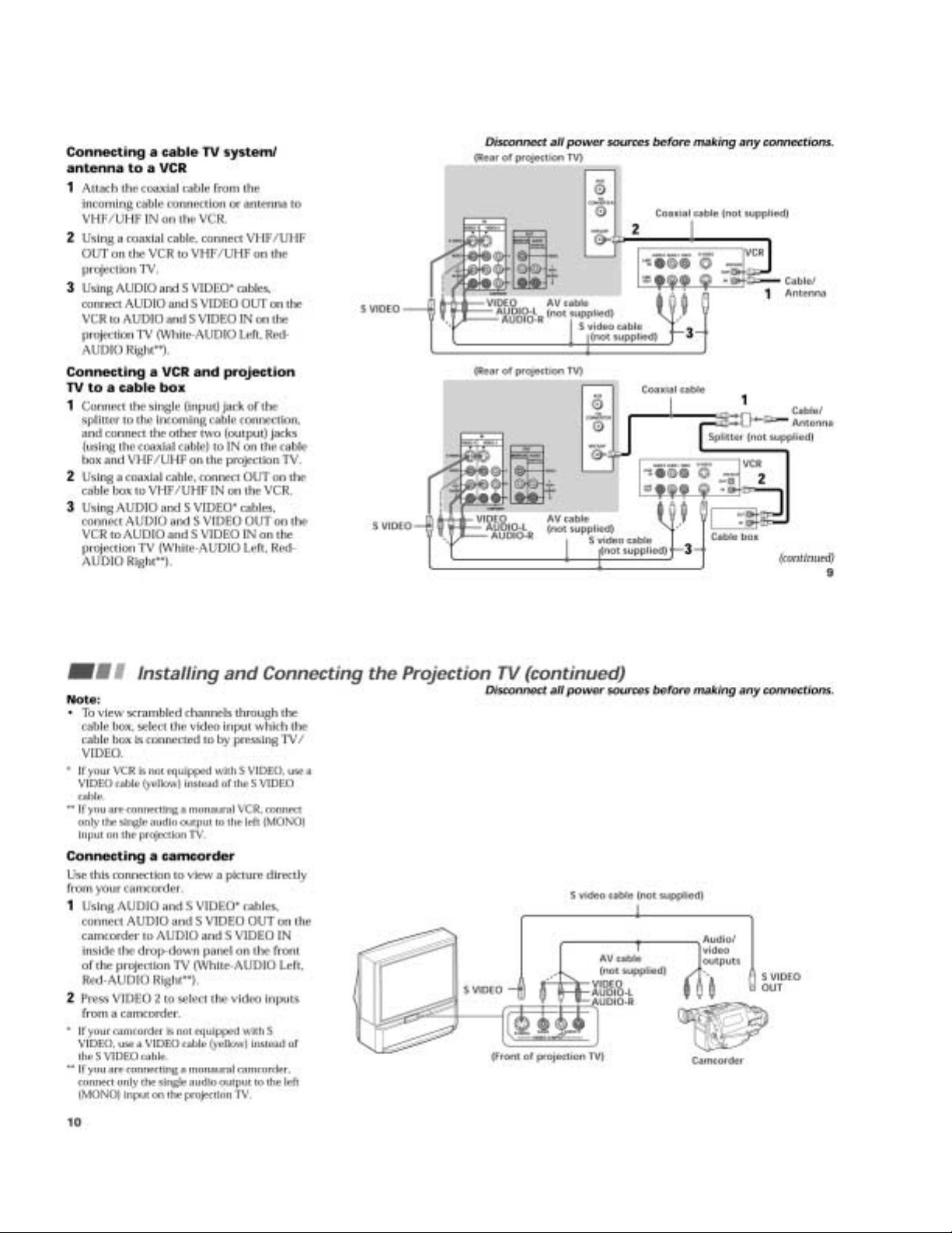
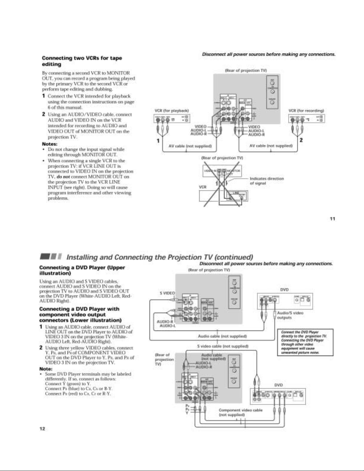
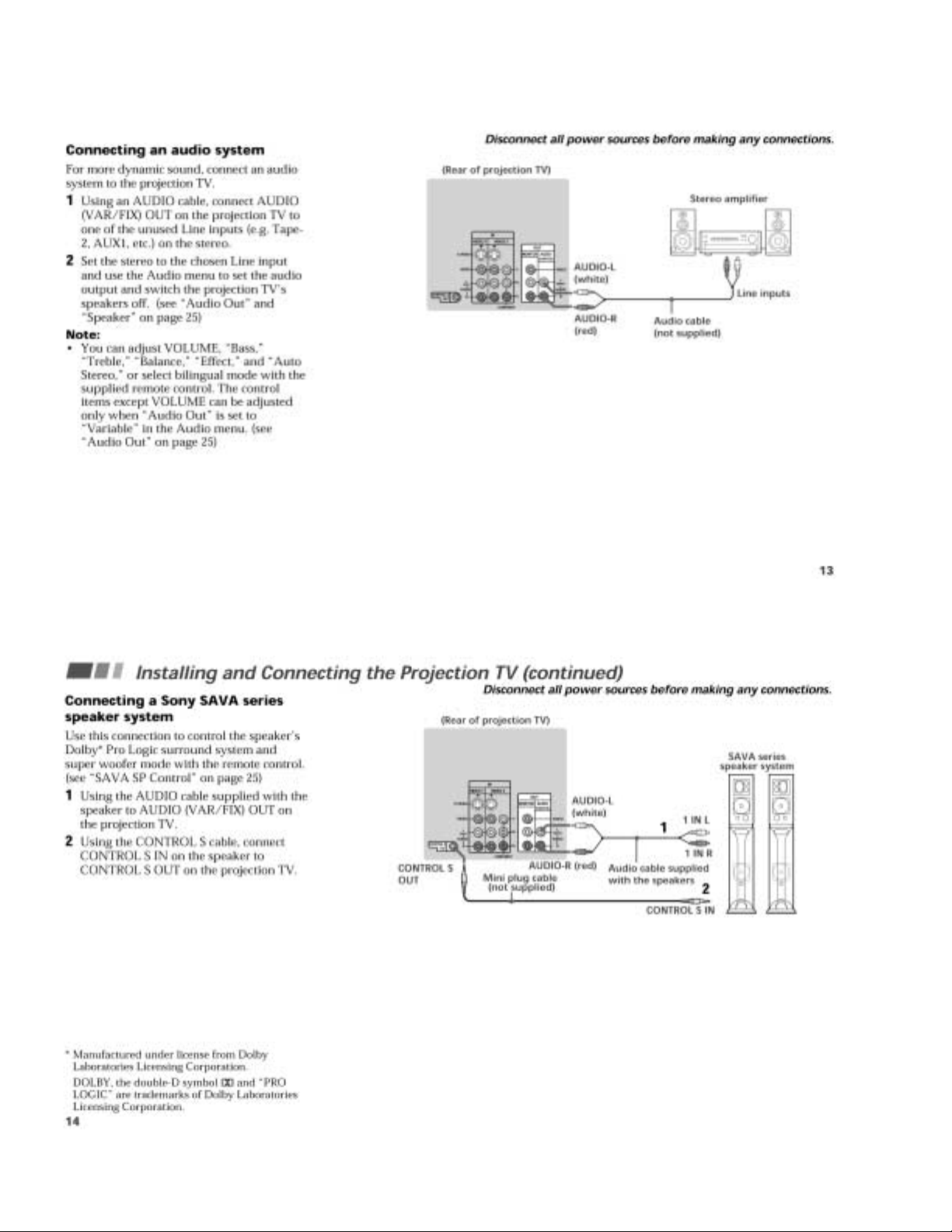
Installing and Connecting the Projection TV .......................... 8
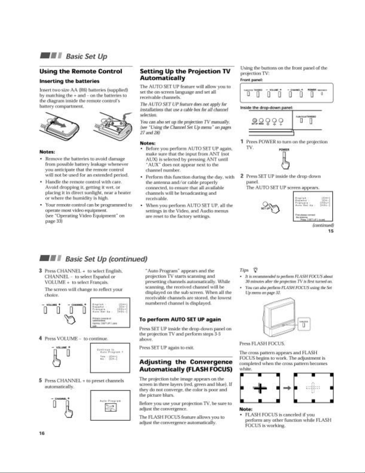
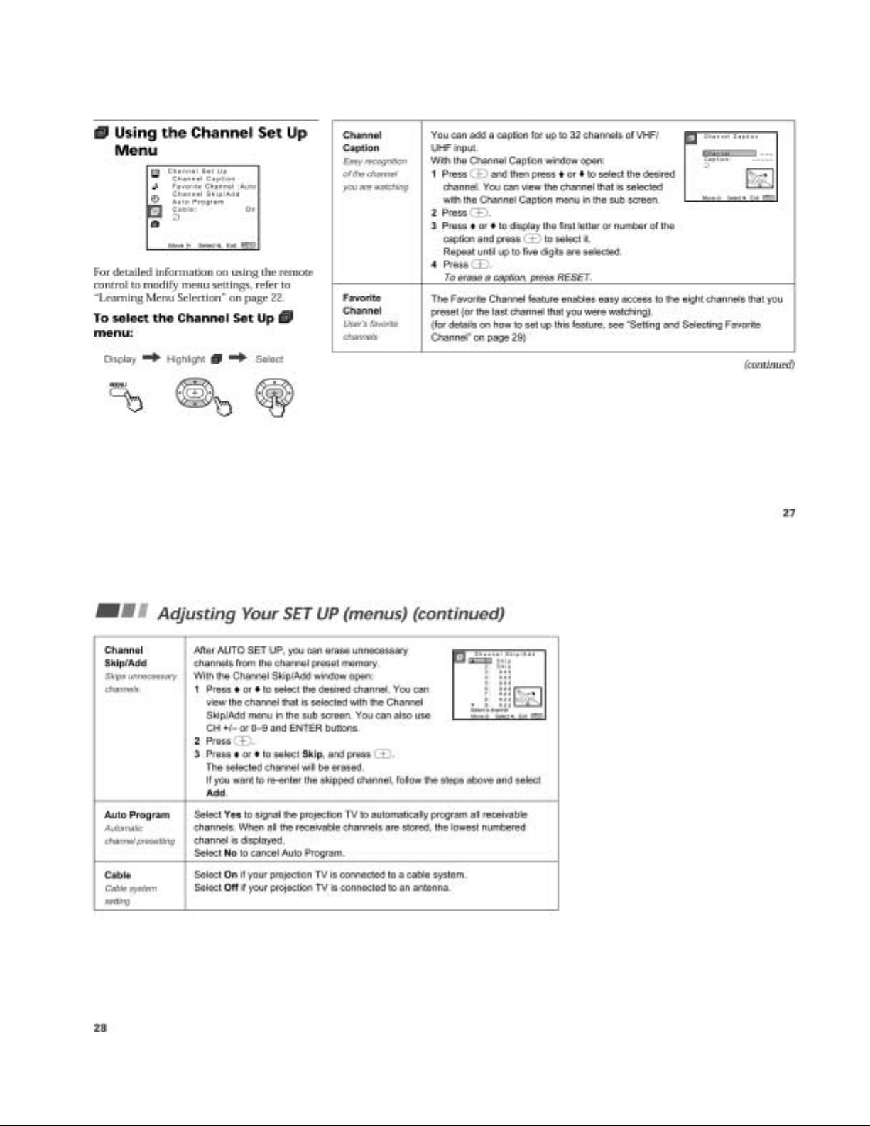
Basic Set Up .......................................................................... 13
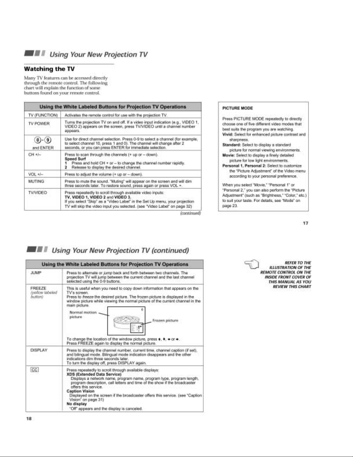
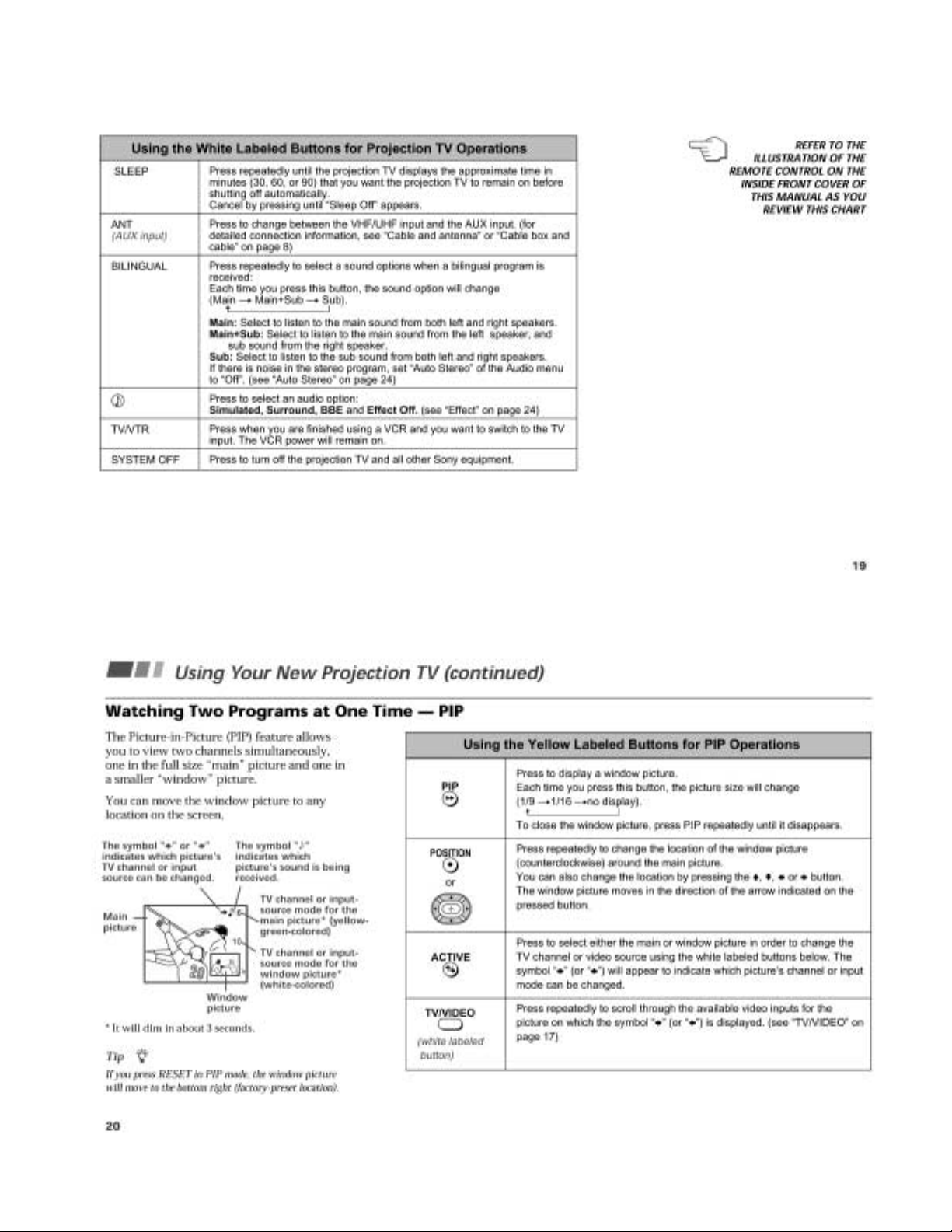
Using Your New Projection TV ............................................ 14
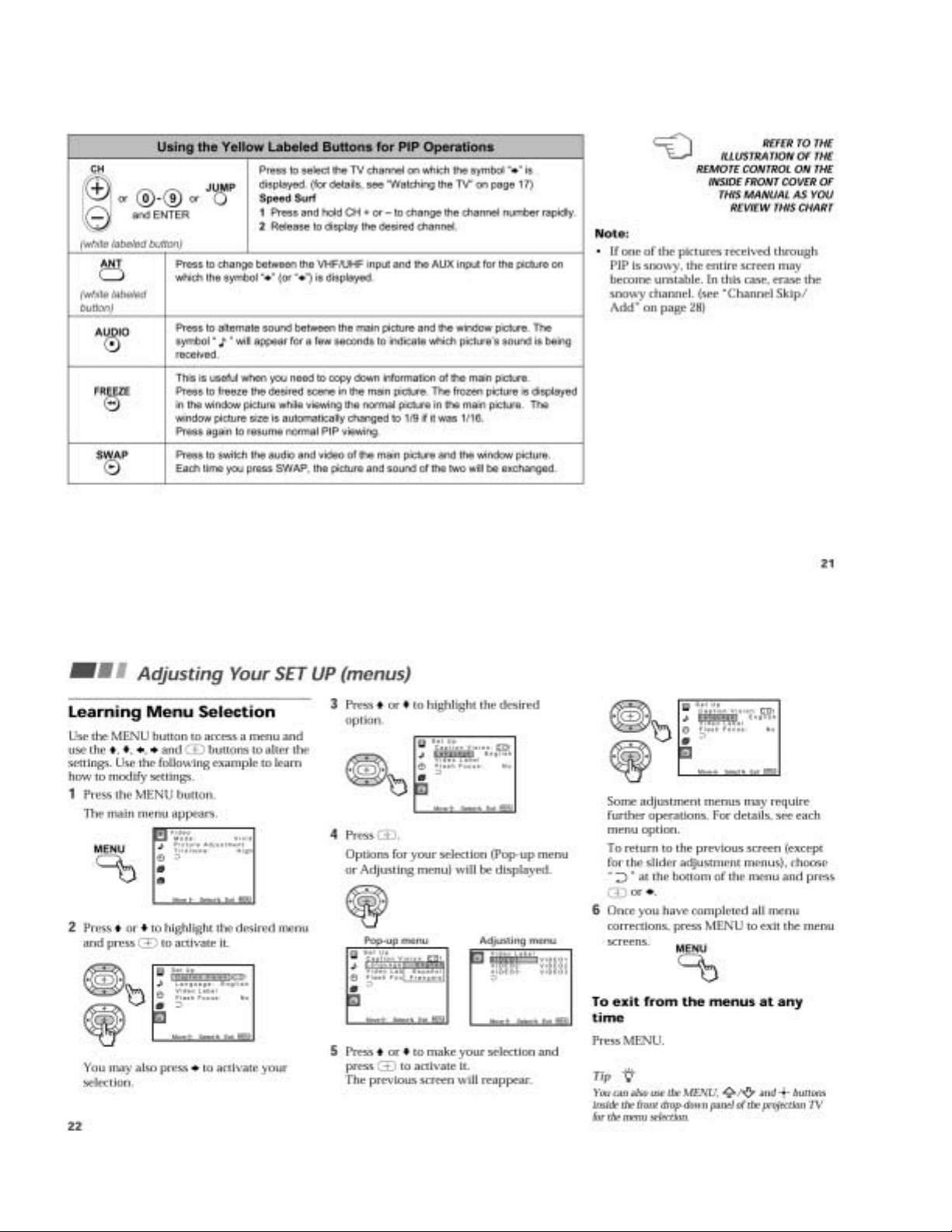
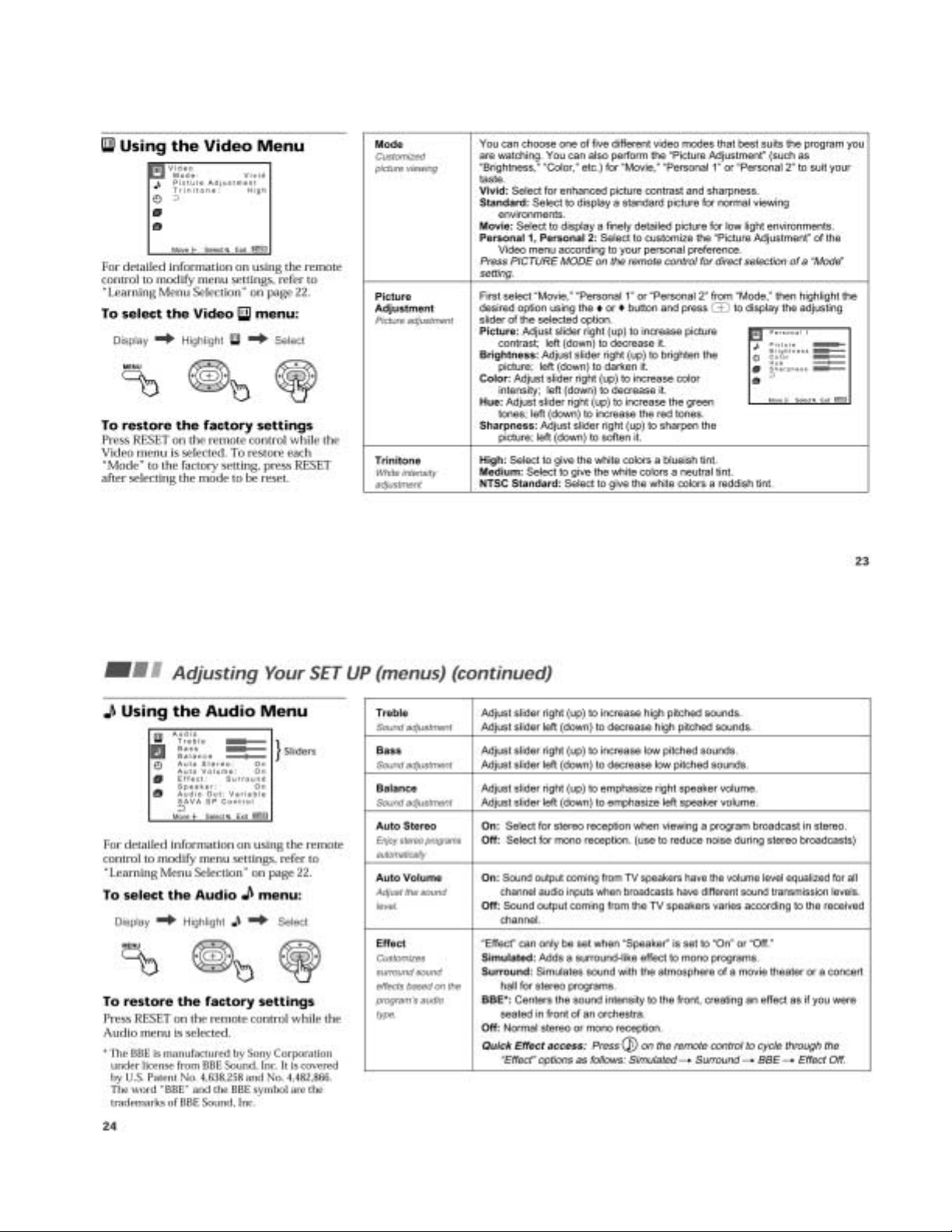
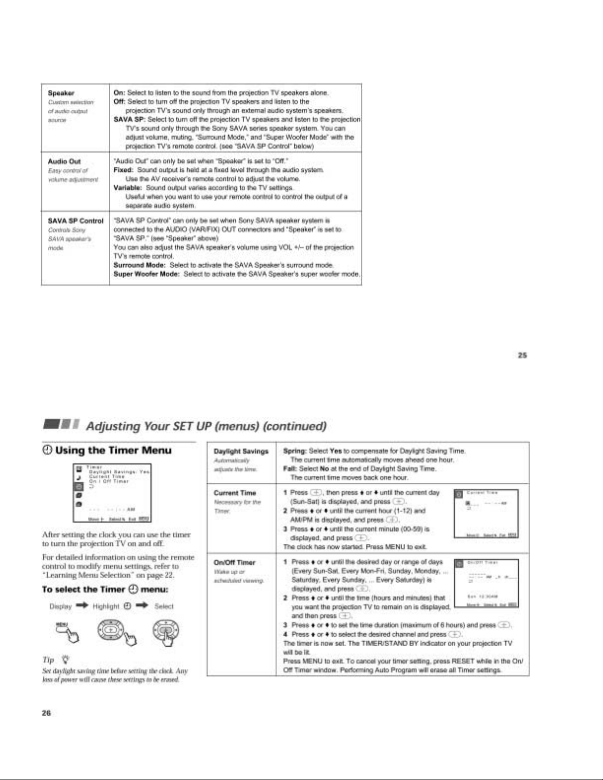
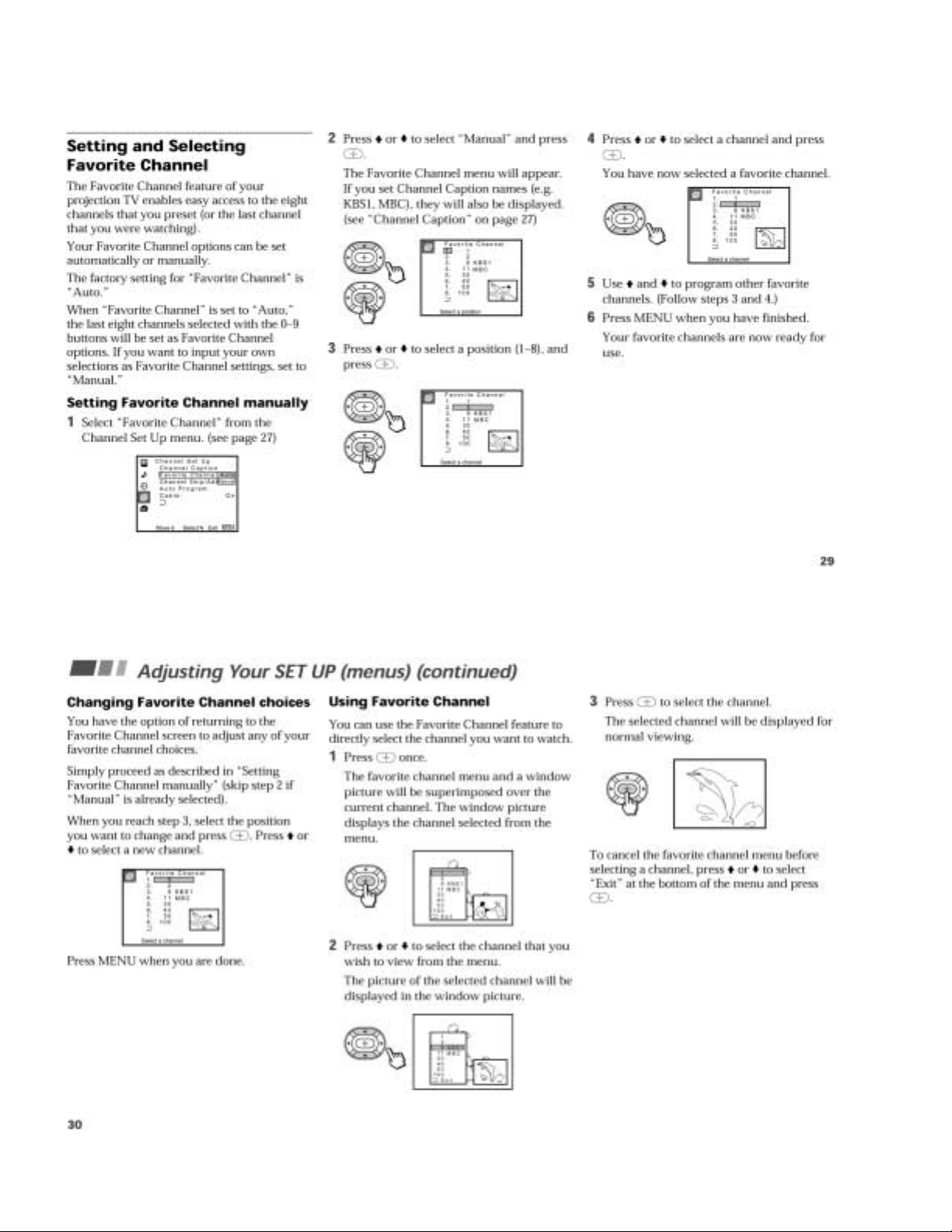
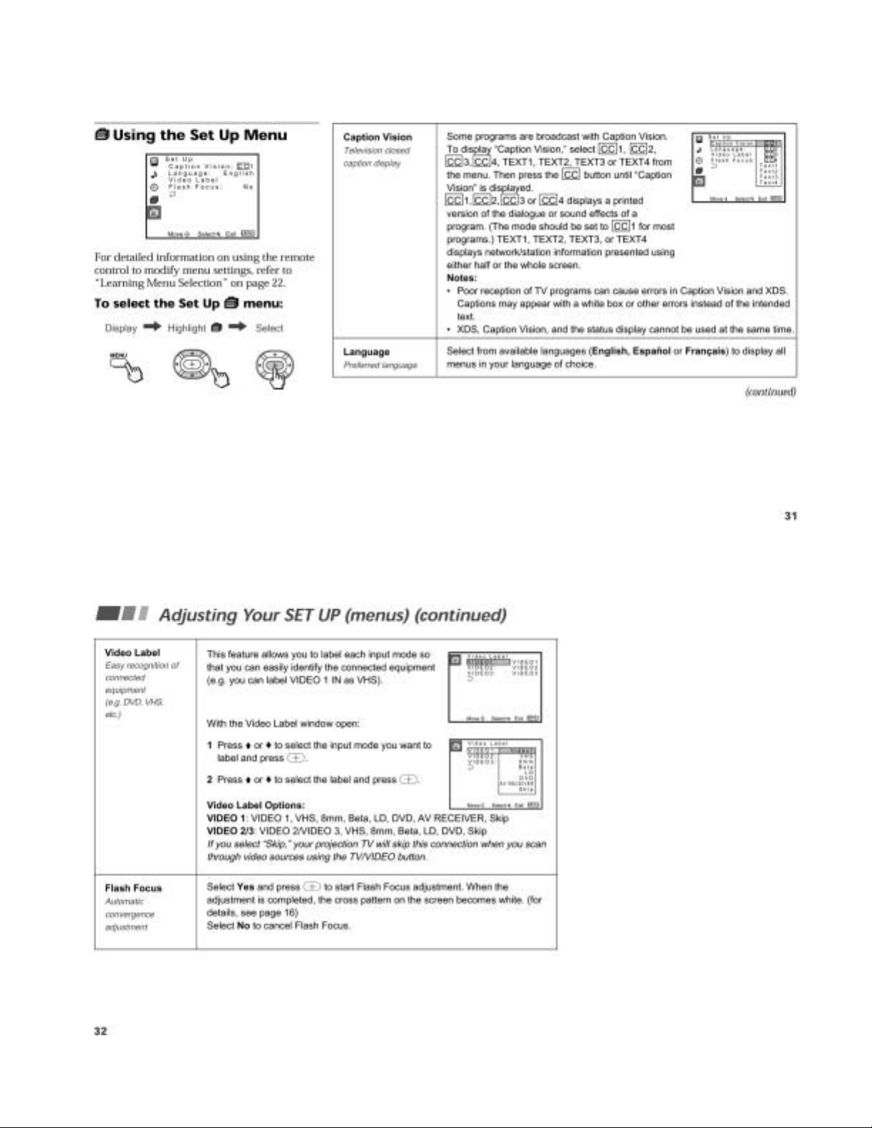
Adjusting Your SET UP (menus) .......................................... 16
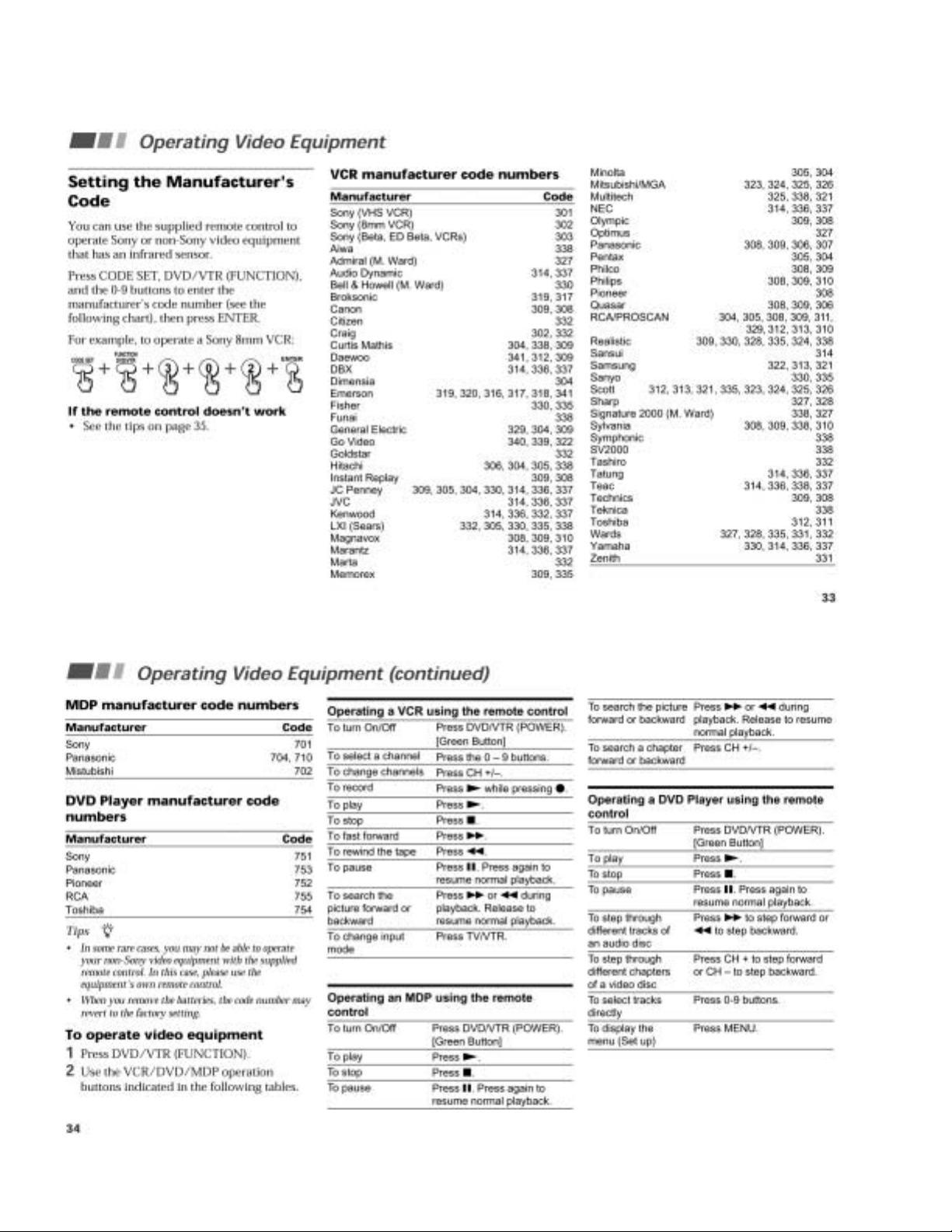
Operating Video Equipment .................................................. 22
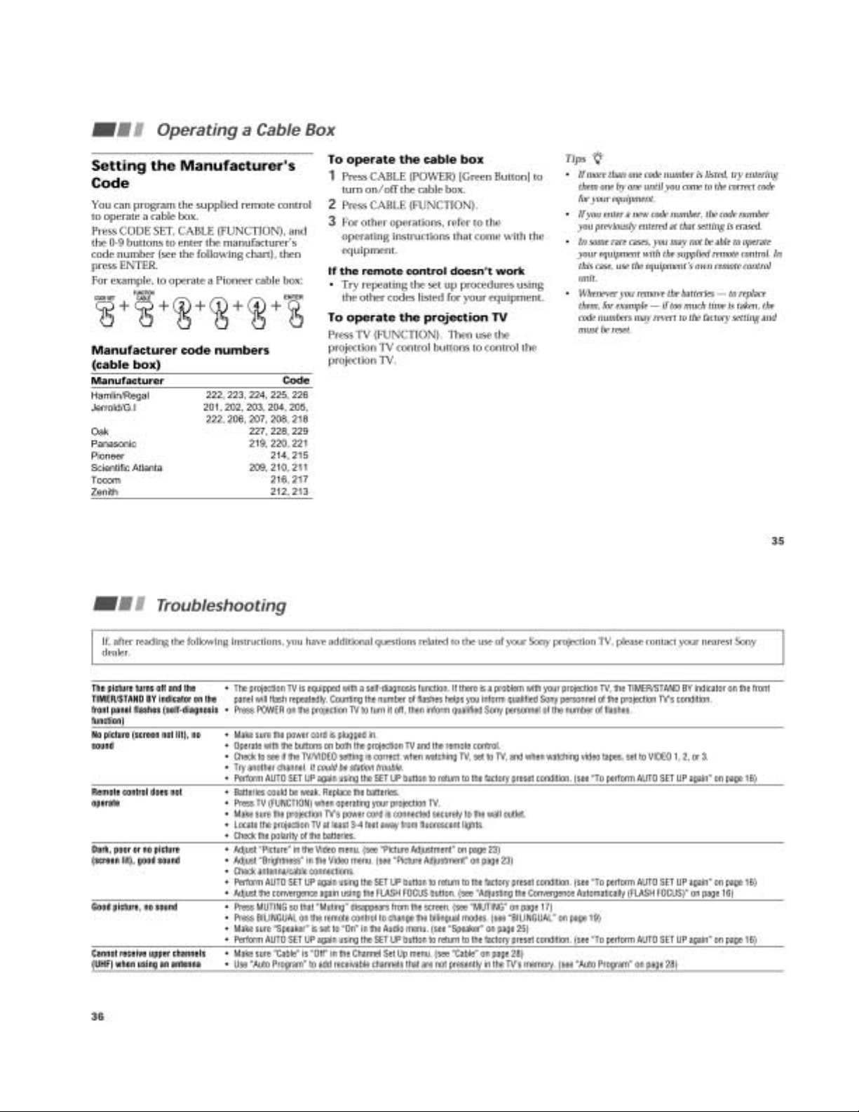
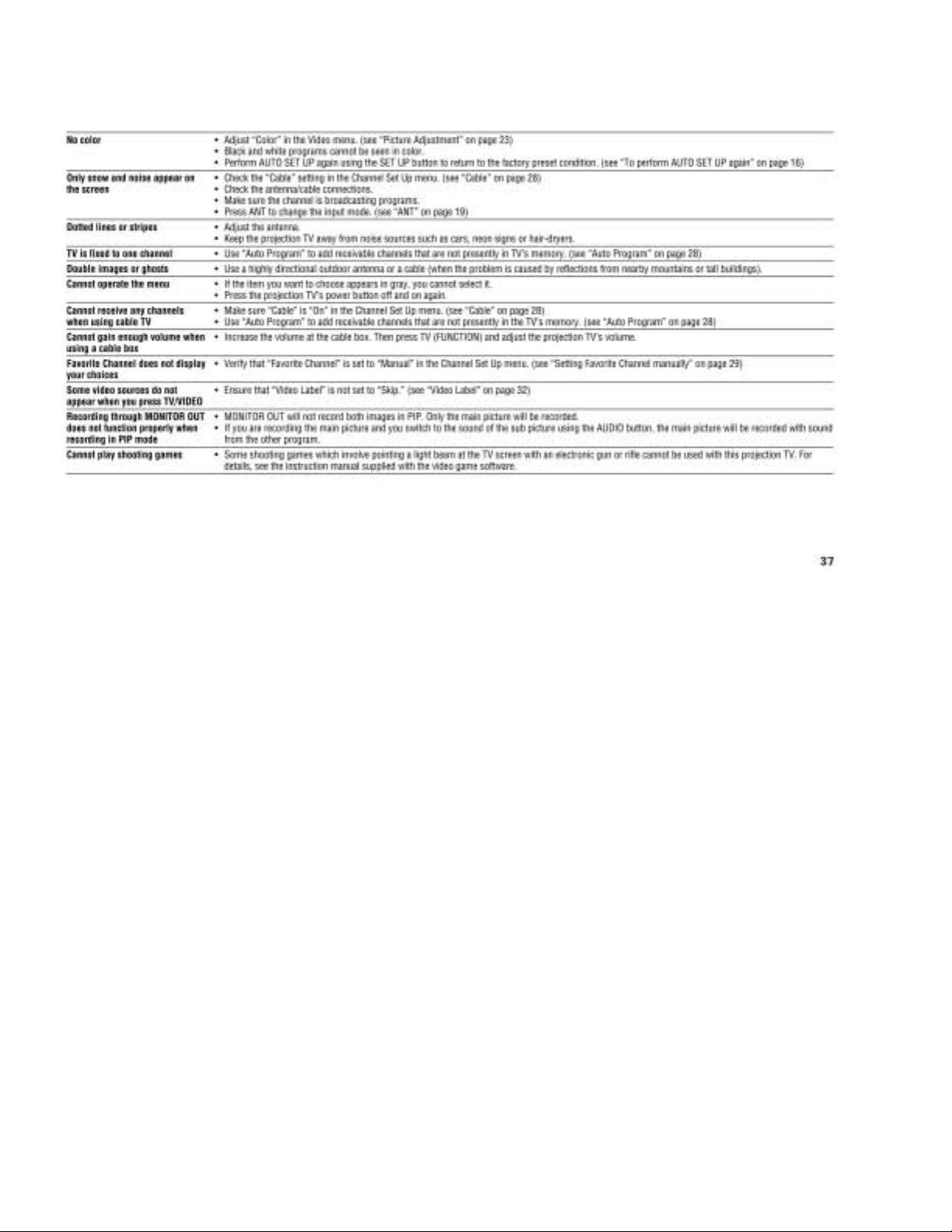
Operating a Cable Box .......................................................... 23
Troubleshooting .................................................................... 23
2. DISASSEMBLY
2-1. Rear Board Removal ................................................. 25
2-2. Chassis Assy Removal .............................................. 25
2-3. Service Position ......................................................... 25
2-4. HA Board and HB Board Removal
(Except KP-XR43KR1/XR43TW1) .......................... 25
2-5. HA and HB Board Removal
(KP-XR43KR1/XR43TW1) ...................................... 26
2-6. Mirror Cover Removal .............................................. 26
2-7. Beznet Assy Removal................................................ 26
2-8. HC Board Removal ................................................... 26
2-9. A, G and FA Boards Removal ................................... 27
2-10. Picture Tube Removal ............................................... 27
2-11. High-Voltage Cable Installation and Removal .......... 27
3. SET-UP ADJUSTMENTS
3-1. Screen Voltage Adjustment (Coarse Adjustment) ..... 28
3-2. Screen (G2) Adjustment (Fine Adjustment) .............. 28
3-3. Deflection York Tilt Adjustment ............................... 28
3-4. Focus Lens Adjustment ............................................. 28
3-5. Focus VR Adjustment ............................................... 29
3-6. 2-Pole Magnet Adjustment (Green, Red) .................. 29
3-7. 4-Pole Magnet Adjustment........................................ 29
3-8. Defocus Adjustment (Blue) ....................................... 29
3-9. Electrical Adjustment by Remote Commander......... 30
3-10. Registration Adjustment(PJE) ................................... 35
3-11. Auto Registration Error Code List ............................ 38
4. SAFETY RELATED ADJUSTMENTS
4-1. HV Regulation Circuit Check and Adjustment ......... 39
4-2. HV Hold Down Circuit Operation Check and
Adjustment ................................................................ 39
4-3. +B Max Voltage Confirmation .................................. 40
4-4. +B OVP Confirmation............................................... 40
Section Title Page
–––––– –––– ––––
5. CIRCUIT ADJUSTMENTS
5-1. TV Input Sub Contrast Adjustment
(VPNT-SCON) .......................................................... 41
5-2. VIDEO Input Sub-HUE and Sub-Color Adjustment
(VPNT-SHUE, SCOL) .............................................. 41
5-3. Component Input Sub-HUE and Sub-Color
Adjustment (DAC-UVSH, UVSC) ........................... 41
5-4. P&P Sub Contrast Adjustment (SC-SYDR) ............. 41
5-5. Sub-HUE, Sub-Color and Main Contrast
Adjustment (MC-MYDR, MSHU, MSCL,
SC-SSHU,SSCL) ...................................................... 42
5-6. Bar Display Position Adjustment
(OP-DISP) ................................................................ 42
5-7. PIP Position Adjustment (PI-PIPH, PIPV)................ 42
6. DIAGRAMS
6-1. Block Diagram (1) ..................................................... 43
Block Diagram (2) ..................................................... 45
Block Diagram (3) ..................................................... 51
Block Diagram (4) ..................................................... 55
Block Diagram (5) ..................................................... 58
6-2. Frame Schematic Diagram ........................................ 61
6-3. Circuit Boards Location ............................................ 64
6-4. Printed Wiring Boards and Schematic Diagrams ...... 64
• A (1/3)Board ........................................................... 65
• A (2/3)Board ........................................................... 69
• A (3/3)Board ........................................................... 73
• G Board ................................................................... 81
• CG Board ................................................................ 88
• CR Board ................................................................ 89
• CB Board ................................................................ 89
• HA Board ................................................................ 91
• HC Board ................................................................ 91
• HB Board ................................................................ 92
• FA Board ................................................................. 93
6-5. Semiconductors ......................................................... 94
7. EXPLODED VIEWS
7-1. Cover (KP-XR43KR1/XR43TW1) ........................... 96
7-2. Cover (Except KP-XR43KR1/XR43TW1) ............... 97
7-3. Chassis (KP-XR43KR1/XR43TW1) ........................ 98
7-4. Chassis (Except KP-XR43KR1/XR43TW1) ............ 99
7-5. Picture Tube ............................................................ 100
8. ELECTRICAL PARTS LIST ................................. 101
(CAUTION)
SHORT CIRCUIT THE ANODE OF THE PICTURE TUBE AND THE
ANODE CAP TO THE METAL CHASSIS, CRT SHIELD, OR CARBON PAINTED ON THE CRT, AFTER REMOVING THE ANODE.
WARNING!!
AN ISOLATION TRANSFORMER SHOULD BE USED DURING
ANY SERVICE TO AVOID POSSIBLE SHOCK HAZARD, BECAUSE OF LIVE CHASSIS.
THE CHASSIS OF THIS RECElVER IS DIRECTLY CONNECTED
TO THE AC POWER LINE.
SAFETY-RELATED COMPONENT WARNING!!
COMPONENTS IDENTIFIED BY SHADING AND MARK ! ON THE
SCHEMATIC DIAGRAMS, EXPLODED VIEWS AND IN THE
PARTS LIST ARE CRITICAL TO SAFE OPERATION. REPLACE
THESECOMPONENTS WITH SONY PARTS WHOSE PART NUMBERS APPEAR AS SHOWN IN THIS MANUAL OR IN SUPPLEMENTS PUBLISHED BY SONY. CIRCUIT ADJUSTMENTS THAT
ARE CRITICAL TO SAFEOPERATION ARE IDENTIFIED IN THIS
MANUAL. FOLLOW THESE PROCEDURES WHENEVER CRITICAL COMPONENTS ARE REPLACED OR IMPROPER OPERATION IS SUSPECTED.
– 6 –
SECTION 1
GENERAL
The operating instructions mentioned here are partial abstracts from the
Operating Instructions Manual. The page numbers of the Operating
Instruction Manual remain as in the manual. (Part no :4-078-175-11)
– 7 –
– 8 –
– 9 –
– 10 –
– 11 –
– 12 –
– 13 –
– 14 –
– 15 –
– 16 –
– 17 –
– 18 –
– 19 –
– 20 –
– 21 –
– 22 –
– 23 –
– 24 –
KP-XR43KR1/XR43TW1/XR48KR1/XR53KR1/XR53TW1
RM-Y906K RM-Y906 RM-Y906K RM-Y906K RM-Y906
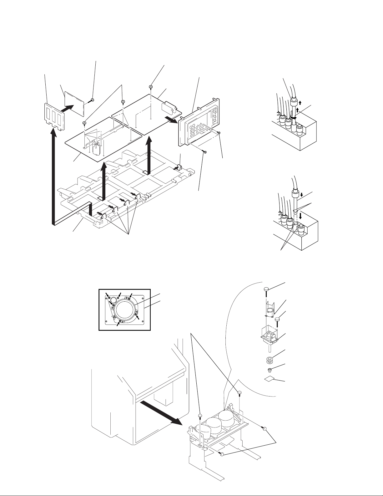
SECTION 2
DISASSEMBLY
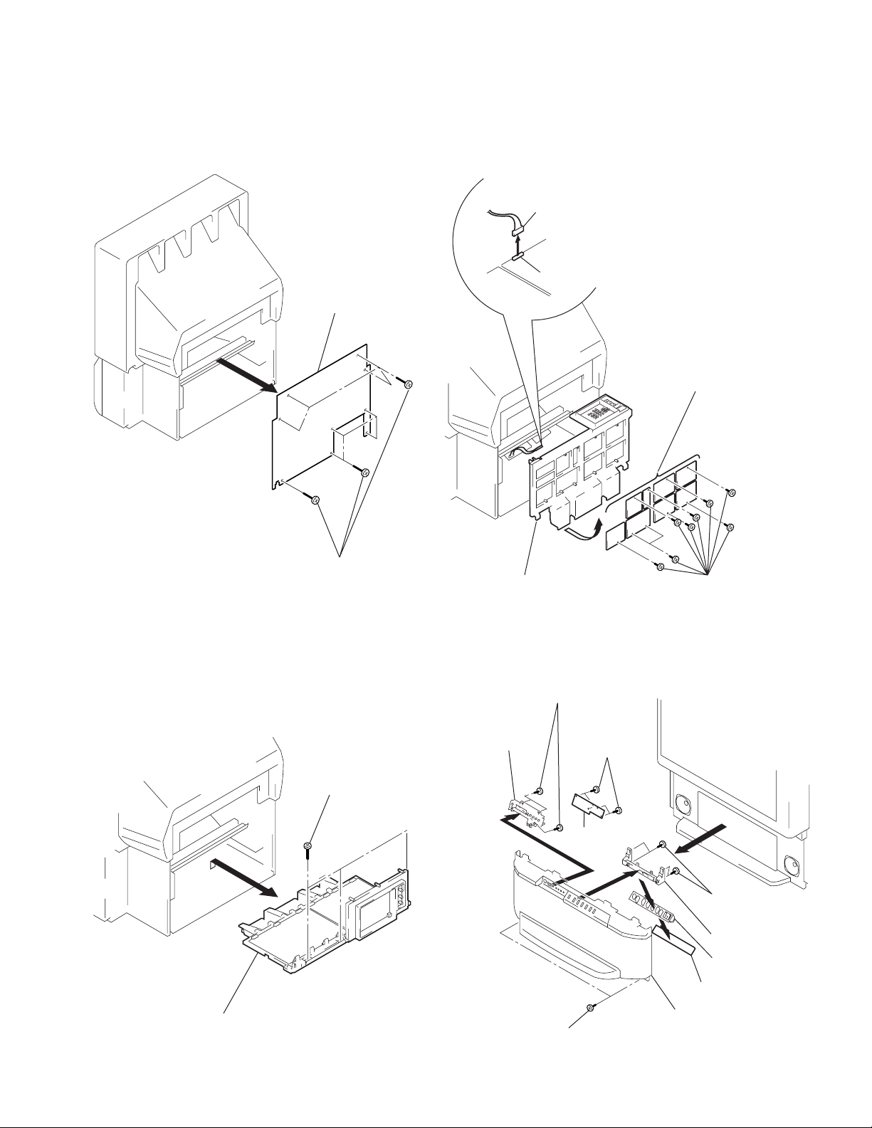
2-1. REAR BOARD REMOVAL 2-3. SERVICE POSITION
1 Disconnect CN203
on A board.
From CG board CN1304.
(The extension cable is not
supplied because of the
countermeasure for radiation.)
2 Covers
Cut them off with a plier or the like
from chassis assembly in case of
checking printed circuit boards.
After checking, turn over the covers
and secure them with screws.
2 Rear board
A board
CN203
G board
1 Nine screws
(Except KP-XR43KR1/XR43TW1)
Eight screws
(KP-XR43KR1/XR43TW1)
(Screw(4x20), tapping)
2-2. CHASSIS ASSY REMOVAL
1 Three screws
(Screw(4x20),tapping)
Chassis assembly
Screws
(+BVTP3x12)
2-4. HA BOARD AND HB BOARD REMOVAL
(EXCEPT KP-XR43KR1/XR43TW1)
6 Four screws
(+BVTP 4x16)
7 HB bracket
8 Three screws
(+BVTP 3x12)
9 HB board
2 Four screws
(+BVTP 4x16)
3 HA bracket
4 Multi button
2 Chassis assy
5 HA board
Speaker grille assy
1 Two screws
(Screws (4x20), tapping)
– 25 –
KP-XR43KR1/XR43TW1/XR48KR1/XR53KR1/XR53TW1
RM-Y906K RM-Y906 RM-Y906K RM-Y906K RM-Y906
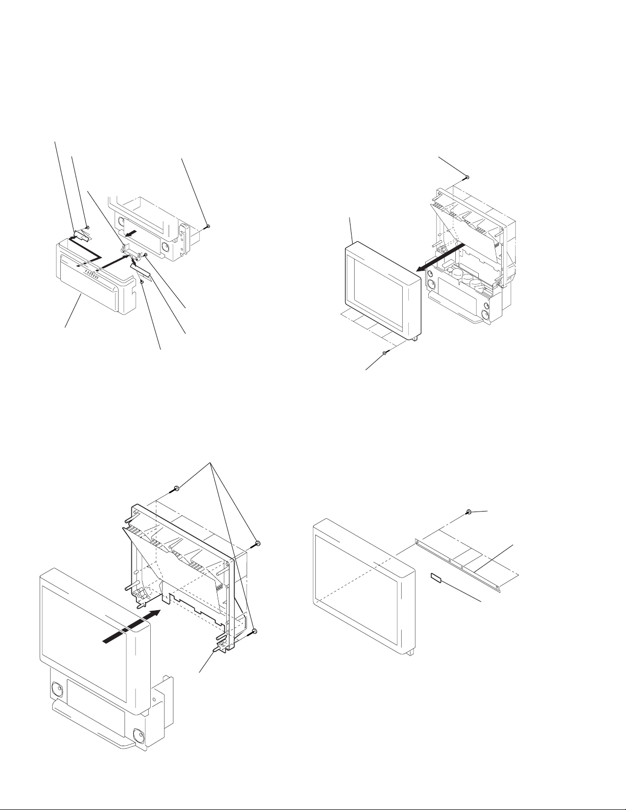
2-5. HA AND HB BOARD REMOVAL
(KP-XR43KR1/XR43TW1)
8 HB board
7 Three screws
(+BVTP 3x12)
4 HA bracket
2
Panel ASSY, Control
1 Four screws
(Screws (4x20), tapping)
3 Four screws
(+BVTP 3x12)
6 HA board
5 Three screws
(+BVTP 3x12)
2-6. MIRROR COVER REMOVAL
1 Seventeen screws (KP-XR43KR1/XR43TW1)
Twenty four screws (KP-XR48KR1)
Nineteen screws (KP-XR53KR1/XR53TW1)
(Screw(4x20), tapping)
2-7. BEZNET ASSY REMOVAL
2 Eleven screws (KP-XR43KR1/XR43TW1)
Twelve screws (KP-XR48KR1)
Fifteen screws (KP-XR53KR1/XR53TW1)
(Screws (4x20), tapping)
3 Beznet assy
1 Three screws
(KP-XR43KR1/XR43TW1/XR48KR1)
Five screws (KP-XR53KR1/XR53TW1)
(Screws (4x20), tapping)
2-8. HC BOARD REMOVAL
2 Mirror cover
1 Two screws
(+BVTP 4x12)
2 L screen holder
3 HC board
– 26 –
KP-XR43KR1/XR43TW1/XR48KR1/XR53KR1/XR53TW1
RM-Y906K RM-Y906 RM-Y906K RM-Y906K RM-Y906
2-9. A, G AND FA BOARDS REMOVAL 2-11. HIGH-VOLTAGE CABLE INSTALLATION
!¡ FA board bracket
!™ FA board
0 Screw
(+BVTP 3x12)
4 Eight screws
(+BVTP 3x12)
7 Two screws
(+BVTP 3x12)
3 Terminal board
9 A board
8 Claw
AND REMOVAL
(1) Removal
1 Rubber cap
2 HV cable
turn 90°
6 G board
Main bracket
5 Claws
2-10. PICTURE TUBE REMOVAL
CAUTION: Removing the arrow-marked
screws is strictly prohibited.
If removed, it may cause liquid spill.
2 Seven screws
(+BVTP 3x12)
1 Two screws
(Screws (4x20), tapping)
Lens
Picture tube
2 Four screws
(Screw(4x20), tapping)
(2) Installation
1 HV cable
Hook
Gutter
4 Four screws
(Screw(4x20), tapping)
5 Lens
9 Four screws
(+BVTP 4x12)
0 Picture tube
3
8 Diflection yoke
7 Neck assy
6 CR board
1 Four screws
(Screw(4x20), tapping)
– 27 –
KP-XR43KR1/XR43TW1/XR48KR1/XR53KR1/XR53TW1
RM-Y906K RM-Y906 RM-Y906K RM-Y906K RM-Y906
SECTION 3
SET-UP ADJUSTMENTS
3-1. SCREEN VOLTAGE ADJUSTMENT
(COARSE ADJUSTMENT)
1. Receive the Monoscope signal.
2. Set 50% BRIGHTNESS and minimum PICTURE.
3. Turn the red VR on the FOCUS block all the way to the left
and then gradually turn it to the right until the point where you
can see the retrace line.
4. Next gradually turn it to the left to the position where the
retrace line disappears.
R G B
SCREEN
R G B
FOCUS
FOCUS block
Fig. 3-1
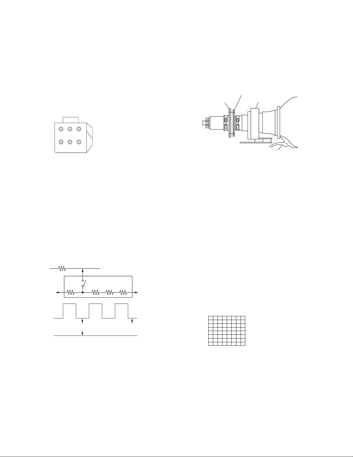
3-2. SCREEN (G2) ADJUSTMENT
(FINE ADJUSTMENT)
Fine Mode is recommended to set screen controls to their optimal
condition. It is necessary to build the simple jig, illustrated below,
using 3-watt resistors. Please note, that if the proper voltage is not
obtained with their listed values, resistors, then please increase or
decrease one of the values in the resistor network to obtain the
correct voltage.
1. Select VIDEO1 mode without signals.
2. Connect G2 JIG.
3. SW on JIG.
4. Connect an oscilloscope to the TP701(KR), TP732(KG) and
TP761(KB) of CR board, CG board and CB board.
5. Adjust R, G and B screen voltage to 168-172V with screen
VR on the Focus block.
K
G2 JIG
3.3k 5.6k 5.6k 5.6k
200V GND
SW
the mode Cover the both green and red picture lenses with the
lens caps is aligned the same as was done for green.
Note: Instead of items 3 and 6, you can cut off the unnecessary
color beams by controlling the service mode VPNT 28 RON,
29 GON, and 30 BON.
4-pole magnet
2-pole magnet
Fig. 3-3
Deflection yoke
Anode cap
3-4. FOCUS LENS ADJUSTMENT
In this adjustment, use the remote commander in the
service mode.
For details of the usage of the service mode and the remote
commander, please refer the item 3-9. ELECTRICAL
ADJUSTMENT BY REMOTE COMMANDER.
1. Loosen the lens screw.
2. Set to the service mode.
3. Receive the all-white signal.
4. Cover the both red and blue picture lenses with the lens caps
to show only the green color.
5. Set to PJE, and press 6 to display the test signal (crosshatch)“
on the screen.
6. Turn the green lens to adjust to the optimum focus point with
the test signal.
7. Tighten the lens screw.
8. Cover the both green and blue picture lenses with the lens caps
to show only the red color.
9. Set to PJE, and press 6 to display the test signal (crosshatch)“
on the screen.
10. Adjust red CRT lens just the same as green.
11. Cover the both green and red picture lenses with the lens caps
to show only the blue color.
175 ± 2V
GND
pedestal level
Fig. 3-2
3-3. DEFLECTION YOKE TILT ADJUSTMENT
1. Receive the Monoscope signal.
2. Set in service mode.
3. Cover the both red and blue picture lenses with the lens caps
to show only the green color.
4. Loosen the deflection yoke set screw and align the tilt of the
Deflection Yoke so that the bars at the center of the
monoscope pattern are horizontal.
5. After aligning the deflection yoke, fasten it securely to the
funnel-shaped portion (neck) of the CRT.
6. The tilt of the deflection yoke for red is aligned in the mode
Cover the both green and blue picture lenses with the lens caps
and the tilt of the deflection yoke for blue is aligned with in
– 28 –
Test signal
Fig. 3-4
12. Set to PJE, and press 6 to display the test signal (crosshatch)“
on the screen.
13. Adjust blue CRT lens just the same as green.
14. After adjusting the items 3-5. Focus VR Adjustment, 3-6. 2Pole Magnet Adjustment and 3-7. 4-Pole Magnet Adjustment,
adjust again to the optimum focus point.
*: Every time you press 6, the test signal changes to
“crosshatch+video signal” - “dots+video signal” -
“crosshach(black)” - “dots(black)” - off.
Note: Instead of items 4, 8 and 11, you can cut off the unnecessary
color beams by controlling the service mode VPNT 28 RON,
29 GON, and 30 BON.
 Loading...