

Sony KPR-53EXR15, KPR-46EXR15 Owner’s Manual
SONY.
3-755-847-22 (1)
t
ColorRearFideoProl'ector
OperatingInstructions[or2models
Before operating the projection TV,'please read this manual
thoroughly and keep itfor future reference.
KPR-41EXR95 KPR-46EXR15
KPR-53EXR15
© 1992 bySonyCorporation
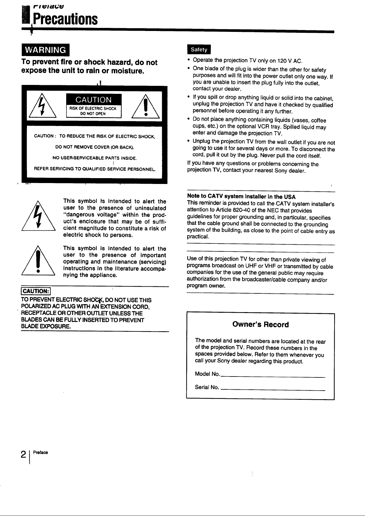
To prevent fire or shock hazard, do not
expose the unit to rain or moisture.
RISK OF ELECTRIC SHOCK
DO NOT OPEN
CAUTION : TO REDUCE THE RISK OF ELECTRIC SHOCK,
DO NOT REMOVE COVER (OR BACK),
NO USER-SERVICEABLE PARTS INSIDE.
REFER SERVICING TO QUALIFIED SERVICE PERSONNEL.
• Operate the projection TV only on 120 V AC.
• One blade of the plug is wider than the other for safety
purposes and will fit into the power outlet only one way. If
you are unable to insert the plug fully into the outlet,
contact your dealer.
• If you spill or drop anything liquid or solid into the cabinet,
unplug the projection TV and have it checked by qualified
personnel before operating it any further.
• Do not place anything containing liquids (vases, coffee
cups, etc.) on the optional VCR tray. Spilled liquid may
enter and damage the projection TV.
• Unplug the projection TV from the wall outlet if you are not
going to use it for several days or more. To disconnect the
cord, pull it out by the plug. Never pull the cord itself.
Ifyou have any questions or problems concerning the
projection -rv, contact your nearest Sony dealer.
This symbol ts intended to alert the
user to the presence of uninsulated
"dangerous voltage" within the prod-
uct's enclosure that may be of suffi-
cient magnitude to constitute a risk of
electric shock to persons.
This symbol is intended to alert the
user to the presence of important
operating and maintenance (servicing)
instructions in the literature accompa-
nying the appliance.
I CAUTION: I
TO PREVENT ELECTRIC SHO_, DO NOT USE THIS
POLARIZED AC PLUG WITH AN EXTENSION CORD,
RECEPTACLE OR OTHER OUTLET UNLESS THE
BLADES CAN BE FULLY INSERTED TO PREVENT
BLADE EXPOSURE.
Note to CATV system Installer in the USA
This reminder is provided to call the CATV system installer's
attention to Article 820-40 of the NEC that provides
guidelines for proper grounding and, in particular, specifies
that the cable ground shall be connected to the grounding
system of the building, as close to the point of cable entry as
practical.
Use of this projection TV for other than private viewing of
programs broadcast on UHF or VHF or transmitted by cable
companies for the use of the general public may require
authorization from the broadcaster/cable company and/or
program owner.
Owner's Record
The modelandserialnumbers are locatedatthe rear
ofthe projection TV. Recordthesenumbersinthe
spacesprovidedbelow.Refertothemwheneveryou
callyourSonydealerregardingthisproduct.
Model No.
1 Preface
Serial No.
Contents
Preface
Chapter 1: Setting Up
Precautions.................. :................................................. 2
Welcome ........................................................................ 4
Features ................................................................... 4
Important Information..................................................... 5
Unpacking and Viewing Area ......................................... 6
Locating Controlsand Connectors ................................. 7
Making Antenna Connections ...................................... 13
Connecting Other Equipment ....................................... 15
Connecting a VCR, video disc player
or Camcorder equipped with
an S video output jack ........................................ 15
Connecting a VCR, video disc player
or Camcorder not equipped with
an S video output jack ........................................ 16
Chapter 2: Using Basic Features
Watching TV Programs ................................................ 34
Using Convenient Features .......................................... 35
Mutingthe sound - MUTING .................................. 35
Keeping the displays on-screen - DISPLAY ........... 35
Setting the sleep timer - SLEEP ............................. 35
Chapter 3: Using Advanced Features
Watching Two Pictures at Once (PIP) .......................... 38
Adjusting the Projection TV .......................................... 42
Adjusting the picture ................................................ 42
Adjusting the sound ................................................ 47
Customizing the Screen Display ................................... 51
Setting channel captions - CH CAPTION ............... 51
Setting VIDEO LABEL ............................................ 53
Connecting two VCRs (equippedwith an
S video outputjack) fortape editing ................... 17
Connectingtwo VCRs (notequipped with an
S video outputjack) for tape editing ................... 18
Connecting an audio system ................................... 19
Using the On-Screen Menus ........................................ 20
Changing the menu language ................................. 22
Adjusting Color Registration (CONVERGENCE) .......... 24
Setting CABLE ON or OFF .......................................... 26
Presetting TV Channels ............................................... 28
Switchingquickly between
two channels - JUMP ........................................ 35
Previewing the features - DEMO ............................ 35
Selecting a Picture and Sound Mode ........................... 36
UsingTimer-Activated Functions.................................. 54
Setting DAYLIGHT SAVING ................................... 54
Setting the clock- CURRENT TIME SET ............. 55
Setting the ON/OFF TIMER .................................... 57
Setting CHANNEL BLOCK ...................................... 60
Setting FAVORITE CHANNEL ..................................... 62
Using the Pre-Programmed Remote Commander ........ 64
Selecting a VCR mode directly
DIRECT PLAY ................................................... 69
Appendix
Troubleshooting ........................................................... 71
Specifications..................................... _......................... 72
Index .......................................................................... 73
PrefaceI 3
Welcome
WelcOmetotheSony EXR series.Byfollowingthe inst_ inthismanual,youwillbeabletoenjoythe
advancedtechnologywhichbringsyouusefulfeaturesand highqualityviewing.
This manual covers three different models. The illustrations
are based on model KPR-41EXR95. If a particular function
does not apply to your model, this will be noted in the
manual.
We highly recommend that you read this manual before
using your projection TV, to set up and make connections
safely and to make maximum use of the many functions.
Then keep the manual handy for future reference.
Sony'e unique features
• The multi-band VHF/UHF/CATV tuner lets you receive up
to 125 cable channels, for a total of 181 possible off-air
and cable channels.
• The built-in Multichannel TV Sound (MTS) decoder lets
you receive stereo programs and Second Audio Program
(SAP) broadcasts.
• You can receive superior VCR playback by connecting a
VCR with an S video output jack tothe S VIDEO IN jack.
• You can receive hi-fi sound by connecting an audio
system to the audio output jacks.
EXR series special features
• Automatically preset all receivable channels with AUTO
PROGRAM.
• Switch quickly between two channels, using JUMP.
• Watch another TV channel, video or cable image as a
window picture, using Picture-in-Picture.
• Operate the projection TV, plus Sony and most other
manufacturers' video equipment, a cable converter box
and a Sony multidisc player with the supplied Remote
Commander, usingthe Pre-Programmed feature.
• Call up on-screen menus to set time-related functions
(ON/OFF TIMER, CHANNEL BLOCK, DAYLIGHT
SAVING), to customize the screen (CH CAPTION, VIDEO
LABEL) and to adjust the pictureand sound.
• Set optional video equipment on the projectionTV, by
mountingthe optional VCR Tray (see the separate VCR
Tray installation instructions).
I Preface
EXR seriesadvanced technology
• DynamicPictureTM systemadjustspicturecontrast
automaticallyto producemoredetailinboth brightand
darkareasofthe picture.
• VelocityModulation(VM)circuitryproducescleanand
sharpblackandwhitecontrasts.
• Dynamic FocusTM circuitryautomaticallyfocuses the
scanningelectronbeamfor enhancedsharpnessoverthe
entirepicture,especiallyat thecomers.
• TrinitoneTM controlallowsyouto adjustthe picture'scolor
temperature(tint)for the bestpossible co!dr.
ImportantInformation
Please read the followi'nginformation on using and maintaining the projection TV, for optimum viewing quality.
_lbT£
• Poor color registration (the red, green and blue signals do
not ovedap properly) may be caused by the influence of
the earth's magnetism. Correct this with the
CONVERGENCE adjustment (pp. 24- 25).
• Avoid touching the screen, and take care notto scratch
the surface with hard objects.
• Displaying a still picture for long periods of time, for
instance, when using the FREEZE function (p. 40) or
when operating a video game or personal computer, may
damage the picture tube. To avoid this, keep the picture
contrast level low (PICTURE adjustment, pp. 42 - 43).
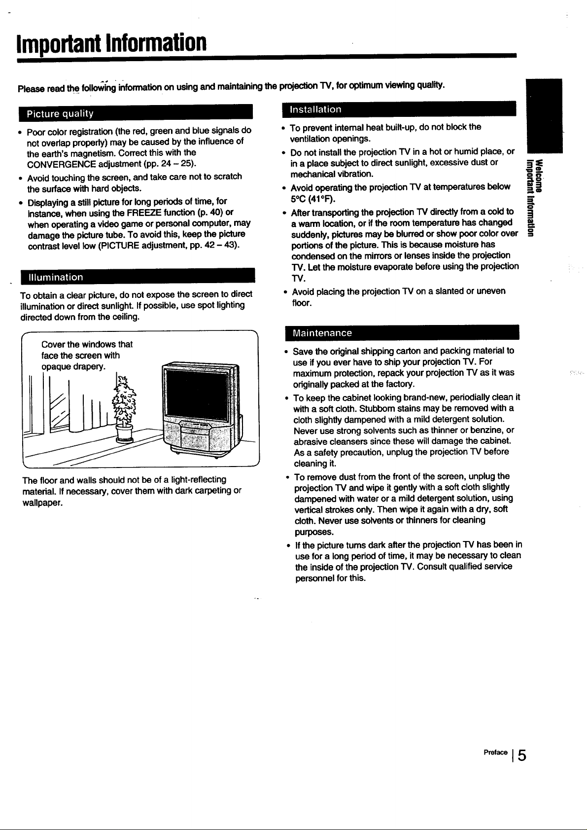
To obtain a clear picture, do not expose the screen to direct
illumination or direct sunlight. If possible, use spot lighting
directed down from the ceiling.
Cover the windows that
face the screen with
opaque drapery.
The floorandwallsshouldnotbe of a light-reflecting
material.Ifnecessary,coverthemwithdarkcarpeting or
wallpaper.
• To prevent intemal heat built-up, do not block the
ventilation openings.
• Do not install the projection TV in a hot or humid place, or
in a place subject to direct sunlight, excessive dust or
mechanical vibration.
• Avoid operating the projection TV at temperatures below
5°C(41°F).
• After transporting the projection TV directly from a cold to
a warm location, or if the room temperature has changed
suddenly, pictures may be blurred or show poor color over
portions of the picture. This is because moisture has
condensed on the mirrors or lenses inside the projection
TV. Let the moisture evaporate before usingthe projection
TV.
• Avoid placing the projection "IV on a slanted or uneven
floor.
• Save the original shipping carton and packing material to
use ifyou ever have to ship your projection TV. For
maximum protection, repack your projection TV as it was
originally packed at the factory.
• To keep the cabinet looking brand-new, periodially clean it
with a soft cloth. Stubbom stains may be removed with a
cloth slightly dampened with a mild detergent solution.
Never use strong solvents such as thinner or benzine, or
abrasive cleansers since these will damage the cabinet.
As a safety precaution, unplug the projection TV before
cleaning it.
• To remove dust from the front of the screen, unplug the
projection TV and wipe it gently with a soft cloth slightly
dampened with water or a mild detergent solution, using
vertical strokes only. Then wipe it again with a dry, soft
cloth. Never use solvents or thinners for cleaning
purposes.
• If the picture tums dark after the projection TV has been in
use for a long period of time, it may be necessary to clean
the inside of the projection TV. Consult qualified service
personnel for this.
_==_.
OL"_
==_!
i
=__
O
=S
I5
I Chapter 1: Setting Up
UnpackingandViewing.area
Carefully follow the instructions on the outside of the
packing carton to unpack the projection TV.
Notes
• The supplied accessories are packed in the bottom of the carton.
Be sure not to throw them away.
• Keep the original carton and packing materials to safely transport
the projection TV inthe future.
Check to make sure that the following is included:
Universal Remote Commander RM-Y112 (1)
with 2 size AA (R6) EVEREADY batteries
If the Remote Commander is missing, contact your dealer.
Placethe projectionTV ina cool,dryplacewherethe
ventilationopeningsat the sidesare notblocked.
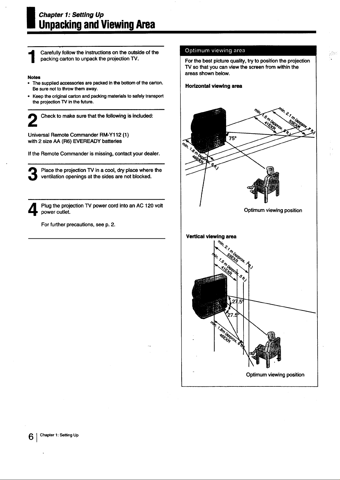
Forthe best picturequality,tryto positiontheprojection
TV sothatyou canviewthe screenfrom withinthe
areasshownbelow.
Horizontal viewing area
Plugthe projectionTV powercordintoanAC 120volt
poweroutlet.
For further precautions, see p. 2.
Optimum viewing position
Vertical viewing area
Optimum viewing position
] Chapter 1: SettingUp
LocatingControlsandConnectors
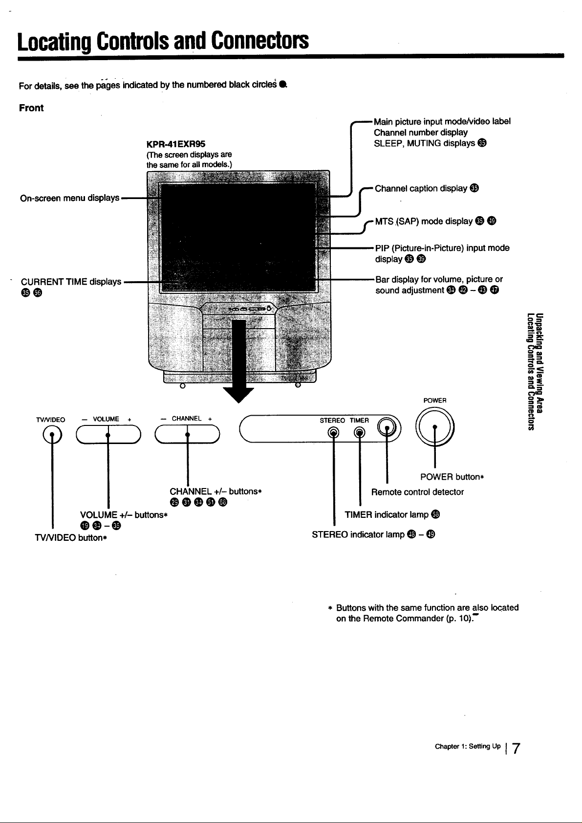
Fordetails,see the pagesindicatedbythe numberedblackcircle,_Q
Front
KPR-41EXR95
(Thescreendisplaysare
the sameforallmodels.)
Mainpictureinputmode/videolabel
Channelnumberdisplay
SLEEP, MUTING displays•
caption display •
MTS.(SAP) mode display • •
PIP (Picture-in-Picture) input mode
display• •
CURRENT
0O
TVN]DEO -- VOLUME +
( , )
VOLUME +/- buttons*
00-0
TVNIDEO button*
-- CHANNEL +
CHANNEL +/- buttons*
00000
Bardisplayfor volume,pictureor
soundadjustment• • - • •
STEREO TIMER
i POWER button*
Remote control detector
TIMER indicator lamp •
STEREO indicator lamp • - •
POWER
€"} -i= I
-__<
=..,
(IIW
0
* Buttonswiththesamefunction are also located
on the Remote Commander(p. 10):
Chapter 1: Setting Up ] 7
LocatingControlsandConnectors
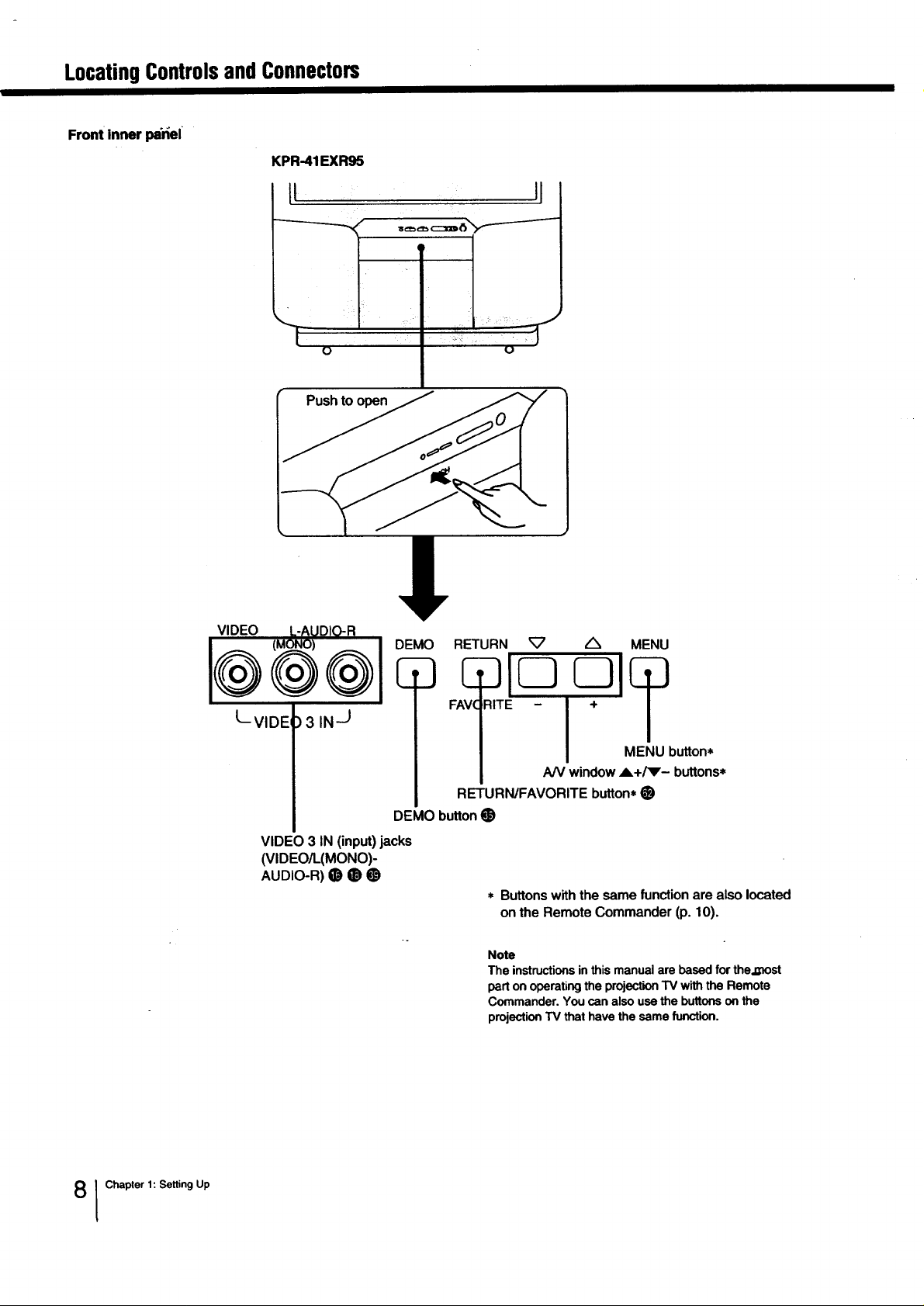
Front inner I_nel
KPR-41EXR95
[I
i
o U
Push to open
VIDEO
@
LVIDEI
@
)3 IN J
VIDE(
3 IN (input) jacks
(VIDEO/L(MONO)-
AUDIO-R)_ _ O
DEMO RETURN
E
RETURN/FAVORITE button* •
DEMO button •
* Buttonswiththe samefunction arealsolocated
Note
The instructions in this manual are based for the._ost
part on operating the projection "IV with the Remote
Commander. You can also use the buttons on the
projection TV that have the same function.
,/_ MENU
MENU button*
AN window A+/_- buttons*
onthe RemoteCommander(p. 10).
I Chapter 1: Setting Up
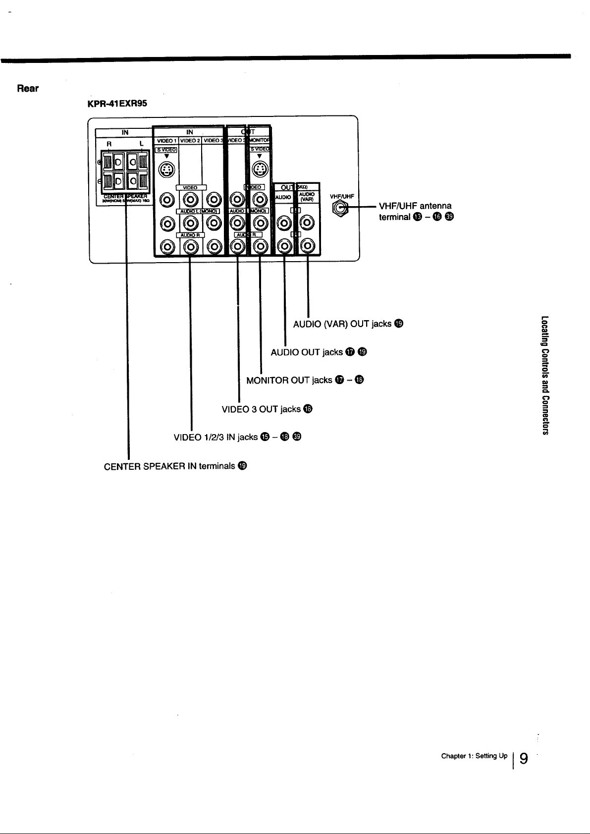
Rear
KPR-41 EXR95
I. '__I°+,,+:_i+
VHF/UHF antenna
terminal• - • •
AUDIO (VAR) OUT jacks •
VIDEO 3 OUT jacks •
VIDEO 1/2/3 IN jacks (_ - • 1_)
CENTER SPEAKER IN terminals •
AUDIO OUT jacks lid •
MONITOR OUT jacks • - •
==-
o_
o
=_
.j
t'l}
t-,
Chapterl:SettingUpI 9
LocatingControlsandConnectors
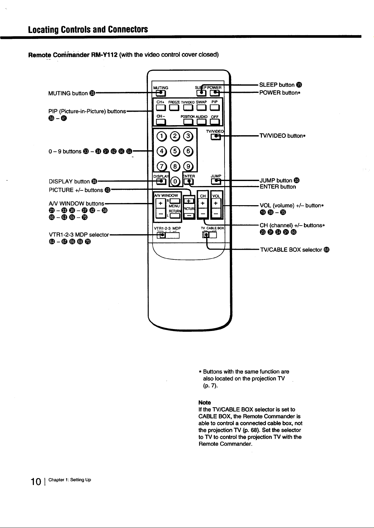
Remote Con_mander RM-Y112 (with the video control cover closed)
MUTING buttonO
PIP (Picture-in-Picture) buttons
O-O
MUT,.G SLI.___..
CH+ FREEZETVNIDEO SWAP PIP
CH- POSITIONAUDIO OFF
FI nnrl
SLEEPbutton•
POWER button*
TVNIDEO button*
0-9 bu"onsO-00000_
DISPLAY button O
PICTURE +/-buttonsO
NV WINDOW buttons,
0-00-00-0
0-00-0
_R1-2-3 MDP selector
0-0000
®®®1
JUMP
JUMP button •
ENTERbutton
CH (channel) +/- buttons*
00000
TV/CABLE BOX selector •
10 1Chapter 1: Setting Up
* Buttons with the same function are
also located on the projection TV
(p.7).
Note
If the TV/CABLE BOX selector is set to
CABLE BOX, the Remote Commander is
able to control a connected cable box, not
the projection TV (p. 68). Set the selector
toTV to control the projection TV with the
Remote Commander.
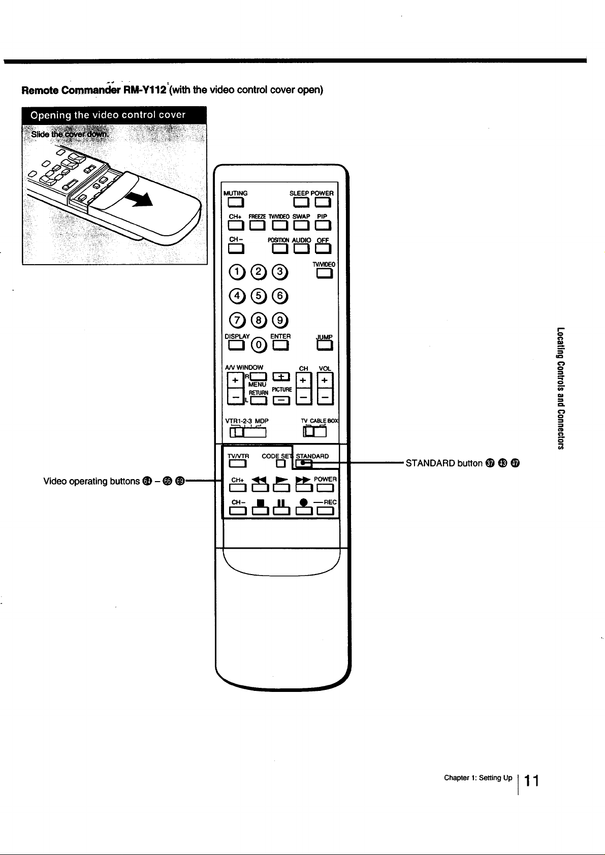
Remote Commen_srRM-Y112=(with the video control cover open)
MUTING SLEEP POWER
r-i r--I C=I
CH+ FREEZEWNIOE0 SWAP PIP
r--i F-I r--i F-1r--!
CH- POSITIONAUDIO OFF
r-l [--i r--i
O (_) (_) _,N,_o
®®®
®®®
Video operating buttons _) - _)
r--!
NV WINDOW CH VOL
r=l
VTR1-2-3 MDP TV CABLESOX
_ STANDARD
STANDARD button _ _)
=_
o
===
o
..=
Q
o
Chapter 1: Setting Up I11
LocatingControlsandConnectors
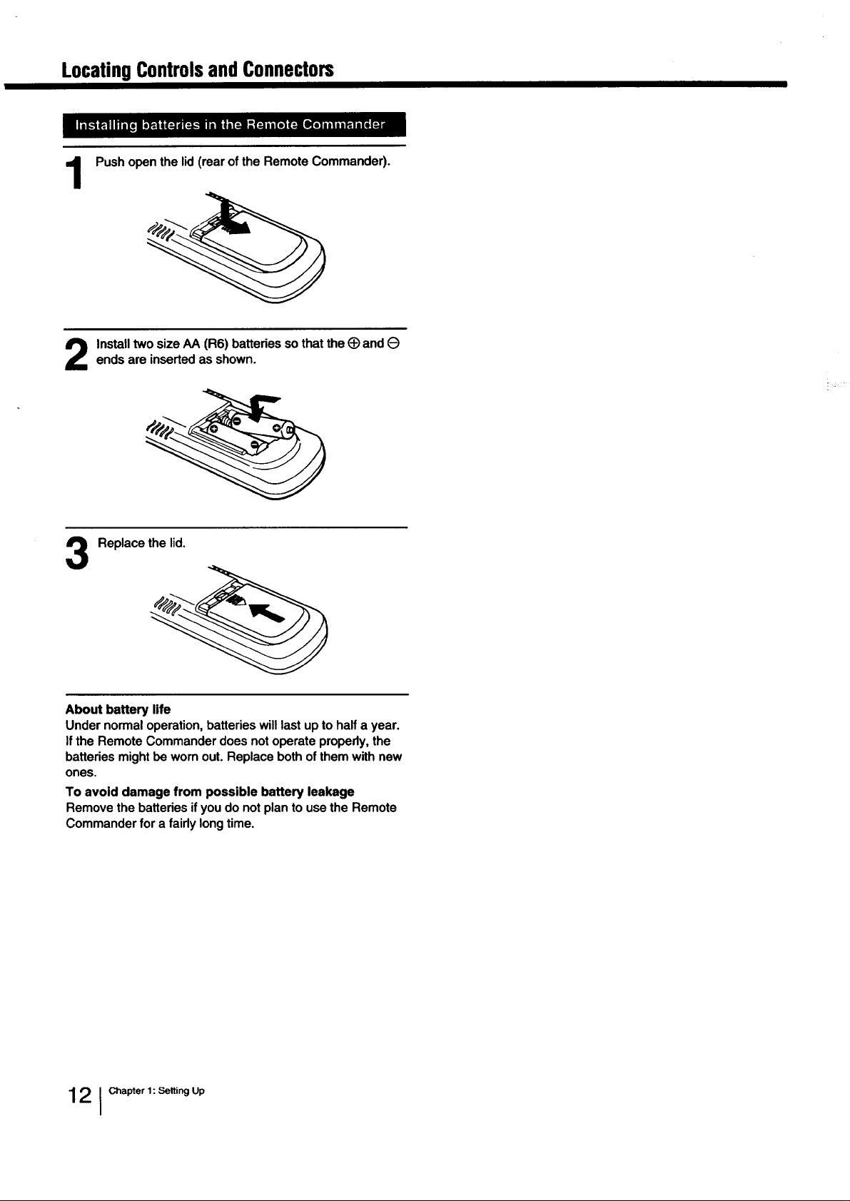
Push open the lid (rear of the Remote Commander).
1
Install two size AA (R6) batteries so that the (_ and Oends are inserted as shown.
Replace the lid,
3
About battery life
Under normal operation, batteries will last up to half a year.
if the Remote Commander does not operate properly, the
batteries might be worn out. Replace both of them with new
ones.
To avoid damage from possible battery leakage
Remove the batteries if you do not plan to use the Remote
Commander for a fairly long time.
12 1Chapter 1: Selting Up
MakingAntennaConnections
- .÷ .
Although you can use either an indoor or outdoor antenna with the projection TV, an outdoor antenna will
provide you with better picture quality.
You can receive cable TV by connecting a cable supplied by your local cable company.
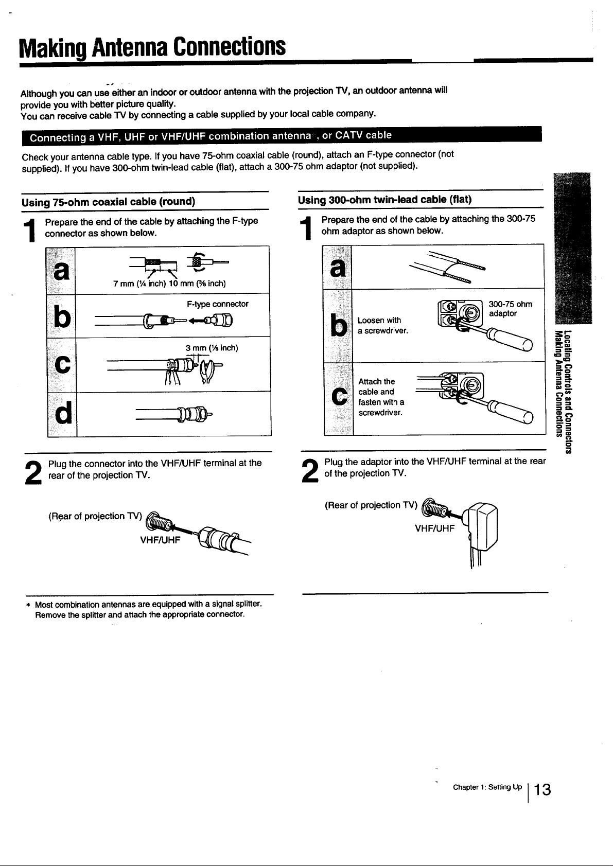
Check your antenna cable type. If you have 75-ohm coaxial cable (round), attach an F-type connector (not
supplied). If you have 300-ohm twin-lead cable (flat), attach a 300-75 ohm adaptor (not supplied).
Using 75-ohm coaxial cable (round)
connector as shown below.
Prepare the end of the cable by attaching the F-type
7 mm(1Ainch) 10 mm (% inch)
F-typeconnector
b
..... 3 mm11,_inch)
Plug the connector into the VHF/UHF terminal at therear of the projection TV.
Using 300-ohm twin-lead cable (flat)
Prepare the end of the cable by attaching the 300-75ohm adaptor as shown below.
_[L-'_--'_I 300-75 ohm
Loosen with
a screwdriver.
Attach the
cable and
fasten with a
screwdriver.
Plug the adaptor into the VHF/UHF terminal at the rearof the projection TV.
¢1 _'J
.=,__
om
•-2 -,i
(Rear of projection TV)
VHF/UHF
* Mostcombinationantennasareequippedwithasignalsplitter.
Removethesplitterandattachthe appropriateconnector.
(Rear of projection TV)
VHF/UHF
Chapter 1: Setting Up I13
MakingAntennaConnections
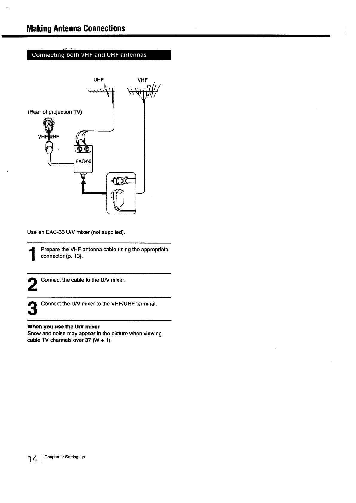
UHF
(Rear of projection TV)
Usean EAC-66UN mixer(notsupplied).
VHF
,,,,,F/Ill
"_,Wl/
Prepare the VHF antenna cable using the appropriate
connector (p. 13).
Connect the cable to the UN mixer.
Connect the UN mixer to the VHF/UHF terminal.
When you use the UN mixer
Snow and noise may appear in the picture when viewing
cable TV channels over 37 (W + 1).
141Chapter'l: Setting Up
ConnectingOtherEquipment
Altermaldngthesec_necUons, youwillbe ableto dothefollowing:
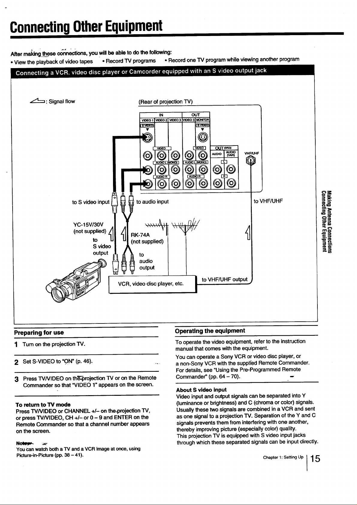
• Viewthe playbackofvideotapes • RecordTV programs • Recordone "IVprogramwhileviewinganotherprogram
/,t___: Signal flow
to S videoinput
YC-15V/30V
(not supplied)
to (not supplied)
S video
output _ to
(Rear of projection TV)
IN OUT
to audio input
A
RK-74A
output
VH
/UHF
toVHF/UHF
_x
O_
===_,
o=-
:=.-!
._'a=
J'=" O_
J I audio
VCR, video disc player, etc.
Preparing for use
1 Turn on the projection "iV.
2 Set S-VIDEO to "ON" (p, 46).
3 Press TVNIDEO on th_orojection TV or on the Remote
Commander so that _VIDEO 1" appears on the screen.
To return to TV mode
PressTV/VIDEO orCHANNEL +/- onthec)rojection TV,
or pressTV/VIDEO, CH +/- or0 - 9and ENTER onthe
RemoteCommandersothata channelnumberappears
on the screen.
You canwatchbotha TV anda VCR imageat once,using
Picture-in-Picture(pp.38- 41).
I to VHF/UHF output
Operating the equipment
To operate the video equipment, refer to the instruction
manual that comes with the equipment.
You can operate a Sony VCR or video disc player, or
a non-Sony VCR with the supplfed Remote Commander.
For details, see "Using the Pre-Programmed Remote
Commander" (pp. 64 - 70).
About S video input
Video input and output signals can be separated into Y
(luminance or brightness) and C (chroma or color) signals.
Usually these two signals are combined in a VCR and sent
as one signal to a projection TV. Separation of the Y and C
signals prevents them from interfering with one another,
thereby improving picture (especially color) quality.
This projection "IV is equipped with S video input jacks
through which these separated signals can be input directly.
Chapter 1: Setting Up I15
ConnectingOtherEquipment
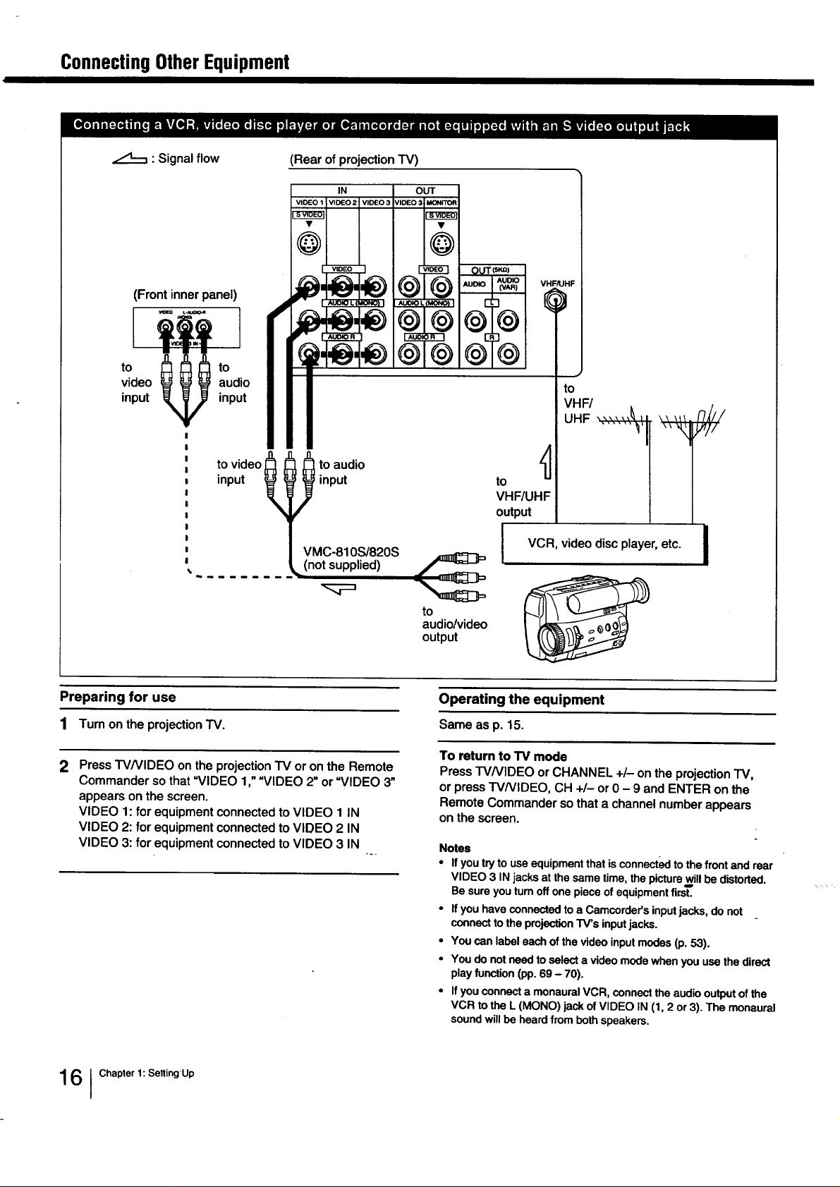
: Signal flow
(Front inner panel)
video audio
input input
to _ to
to video_ _ _ to audio Z_
input _ input to
(Rear of projection TV)
IN OUT
VMC-810S/820S
I
VHF/UHF
Q
to
VHF/
UHF _'_r " ' \ _ _" n_//
VHF/UHF
output
VCR, video disc player, etc. i
,, ,_,.,,_//
II
I
_(not_supplied) _
Preparing for use
1 Turn on the projection TV.
2
Press TV/VIDEO on the projection TV or on the Remote
Commander so that "VIDEO 1,""VIDEO 2" or "VIDEO 3"
appears on the screen.
VIDEO 1: for equipment connected to VIDEO 1 IN
VIDEO 2: for equipment connected to VIDEO 2 IN
VIDEO 3: for equipment connected to VIDEO 3 IN
audio/video
output
Operating the equipment
Same as p. 15.
To return to TV mode
Press TVNIDEO or CHANNEL +/- on the projection "IV,
or press TVNIDEO, CH +1- or 0 - 9 and ENTER on the
Remote Commander so that a channel number appears
on the screen.
Notes
• If you try to use equipment that is connect_l to the front and rear
VIDEO 3 IN jacks at the same time, the picture will be distorted.
Be sure you turn off one piece of equipment first.
• If you have connected to a Camcorder's input jacks, do not
connect to the projection TV's input jacks.
• You can label each of the video input modes (p. 53).
• You do not need to select a video mode when you use the direct
play function (pp. 69 - 70).
• If you connect a monaural VCR, connect the audio output of the
VCR to the L (MONO) jack of VIDEO IN (1, 2 or 3). The monaural
sound will be heard from both speakers.
161Chapter 1: SettingUp
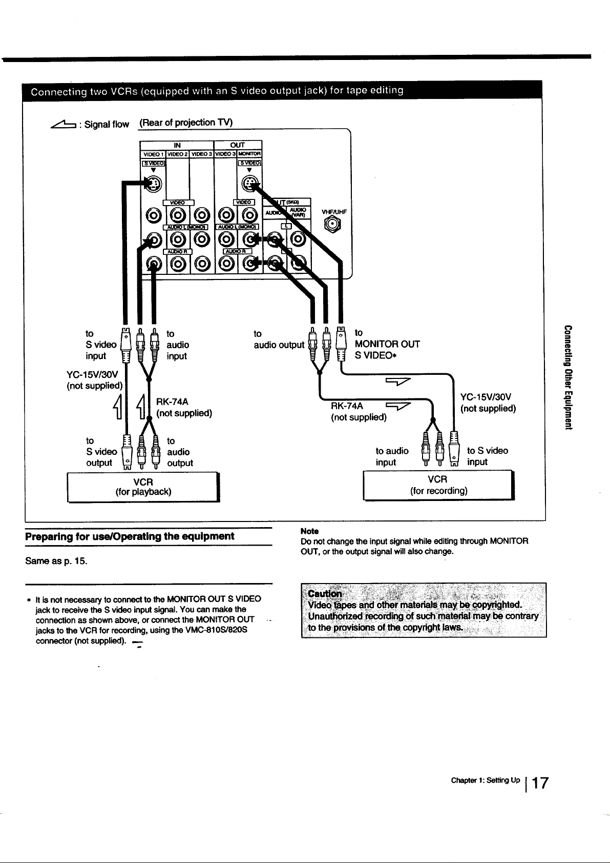
: Signalflow
(Rear of projection TV)
IN OUT
VIDEO2 V1DE03 V1DE03[_
to
S video
input
YC-15V/30V
to to
audio audiooutput
input
RK-74A
(notsupplied)
to
I
S video
output
VCR
(for playback)
audio
to
output
I
Preparing for use/Operating the equipment
Same as p. 15.
* Itis not necessaryto connecttothe MONITOROUT S VIDEO
jackto receivethe S videoinputsignal.You can makethe
connectionasshownabove,orconnect the MONITOR OUT
jacksto theVCR for recording,usingtheVMC-810S/820S
connector (notsupplied). P
to
MONITOR OUT
S VIDEO*
"_YC-15V/30V
(not supplied)
RK-74A _ _ _(not supplied)
Note
Do notchange the input signal while editing through MONITOR
OUT, or the output signal will also change.
to audio to S video
input input
(for recording)
o
=t
€1
€1
o
m
t-
in
=!
=
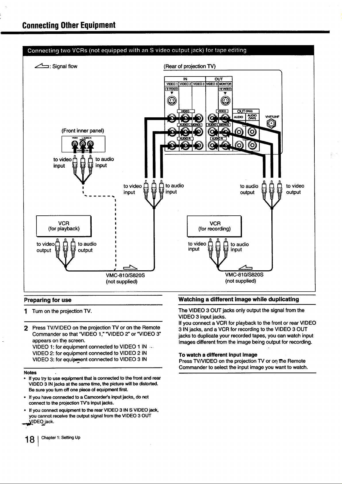
ConnectingOtherEquipment
_'q--q: Signal flow
(Front inner panel)
to video j_ _ _ to audio
input _ input
(Rearofprojection TV)
IN OUT
, to video _ _ _ to audio toaud,o _ tovideo
I , ', . r o 0,o0),/
to video_ _ _ to audio i I tOvideo _ _ _ !O audio --
o ,0u,\ijout0u,! j
VMC-810/S820S VMC-810/$820S
(not supplied) (not supplied)
Preparing for use
1 Tum on the projection TV.
Press W/VIDEO on the projection TV or on the Remote
2
Commander so that =VIDEO 1," =VIDEO 2" or "VIDEO 3"
appears on the screen.
VIDEO 1: for_quipment connected to VIDEO 1 IN ..
VIDEO 2: for equipment connected to VIDEO 2 IN
VIDEO 3: for equil_Lqentconnected to VIDEO 3 IN
Notes
• If you try to use equipment that is connected tothe front and rear
VIDEO 3 IN jacks at the same time, the picture will be distorted.
Be sure you tum off one piece of equipment first.
• If you have connected to a Camcorder's input jacks, do not
connect to the projection TV's inputjacks.
• If you connect equipment to the rear VIDEO 3 IN S VIDEO jack,
you cannot receive the output signal from the VIDEO 3 OUT
,_,l=Y_JDEO_ack.
Watching a different image while duplicating
The VIDEO 3 OUT jacksonlyoutputthe signalfrom the
VIDEO 3 inputjacks.
IfyouconnectaVCR for playbacktothe front or rearVIDEO
3 IN jacks,anda VCR for recordingto the VIDEO 3 OUT
jacksto duplicateyourrecordedtapes,youcan watch input
images differentfromtheimagebeingoutputforrecording.
To watch a different input image
Press W/VIDEO on the projection TV or on 11_eRemote
Commander to select the input image you want to watch.
1 8 I Chapter 1: Setting Up
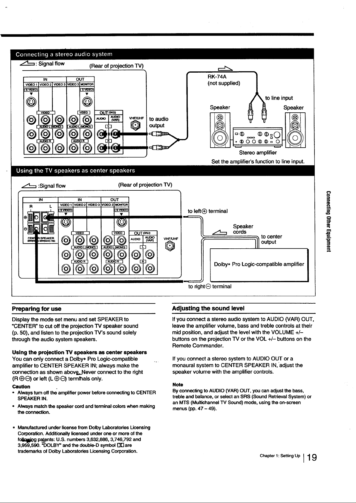
: Signal flow
IN
(Rear of projection TV)
OUT
RK-74A
(not supplied)
to line input
Speaker Speaker
to audio
output
Stereo amplifier
Set the amplifier's function to line input.
:Signal flow
IN IN
R L
(Rear of projection TV)
OUT
Preparing for use
Display the mode set menu and set SPEAKER to
=CENTER" to cut off the projection TV speaker sound
(p. 50), and listen to the projection TV's sound solely
through the audio system speakers.
Using the projection TV speakers as center speakers
You can only connect a Dolby* Pro Logic-compatible ..
amplifier to CENTER SPEAKER IN; always make the
connection as shown abov_,..Never connect to the right
(R (_)O) or left (L (_e) termlhals only.
Caution
• Alwaysturnoff the"amplifierpowerbeforeconnectingto CENTER
SPEAKERIN.
• Alwaysmatchthespeakercordandterminalcolorswhenmaking
theconnection.
to left_) terminal
Speaker
cords
tocenter
output
Dolby* Pro Logic-compatible amplifier
to dghtG terminal
Adjusting the sound level
Ifyou connect a stereo audio system to AUDIO (VAR) OUT,
leave the amplifier volume, bass and treble controls at their
mid position, and adjust the level with the VOLUME +/-
buttons on the projection TV or the VOL +/- buttons on the
Remote Commander.
If you connect a stereo system to AUDIO OUT or a
monaural system to CENTER SPEAKER IN, adjust the
speaker volume with the amplifier controls.
Note
By connecting to AUDIO (VAR) OUT, you can adjust the bass,
treble and balance, or select an SRS (Sound Retrieval System) or
an MTS (Multichannel TV Sound) mode, using the on-screen
menus (pp. 47 - 49).
o
€1
m
€=
o
::r
rIPi
e-
D,
tlD
* Manufactured under license from Dolby Laboratories Ucensing
Corporation. Additionally licensed under one or more of the
fol_g paints: U.S. numbers 3,632,886, 3,746,792 and
3,959,590. "DOLBY" and the double-D symbol O_are
trademarks of Dolby Laboratodes Licensing Corporation.
Chapter 1: Setting Up 119
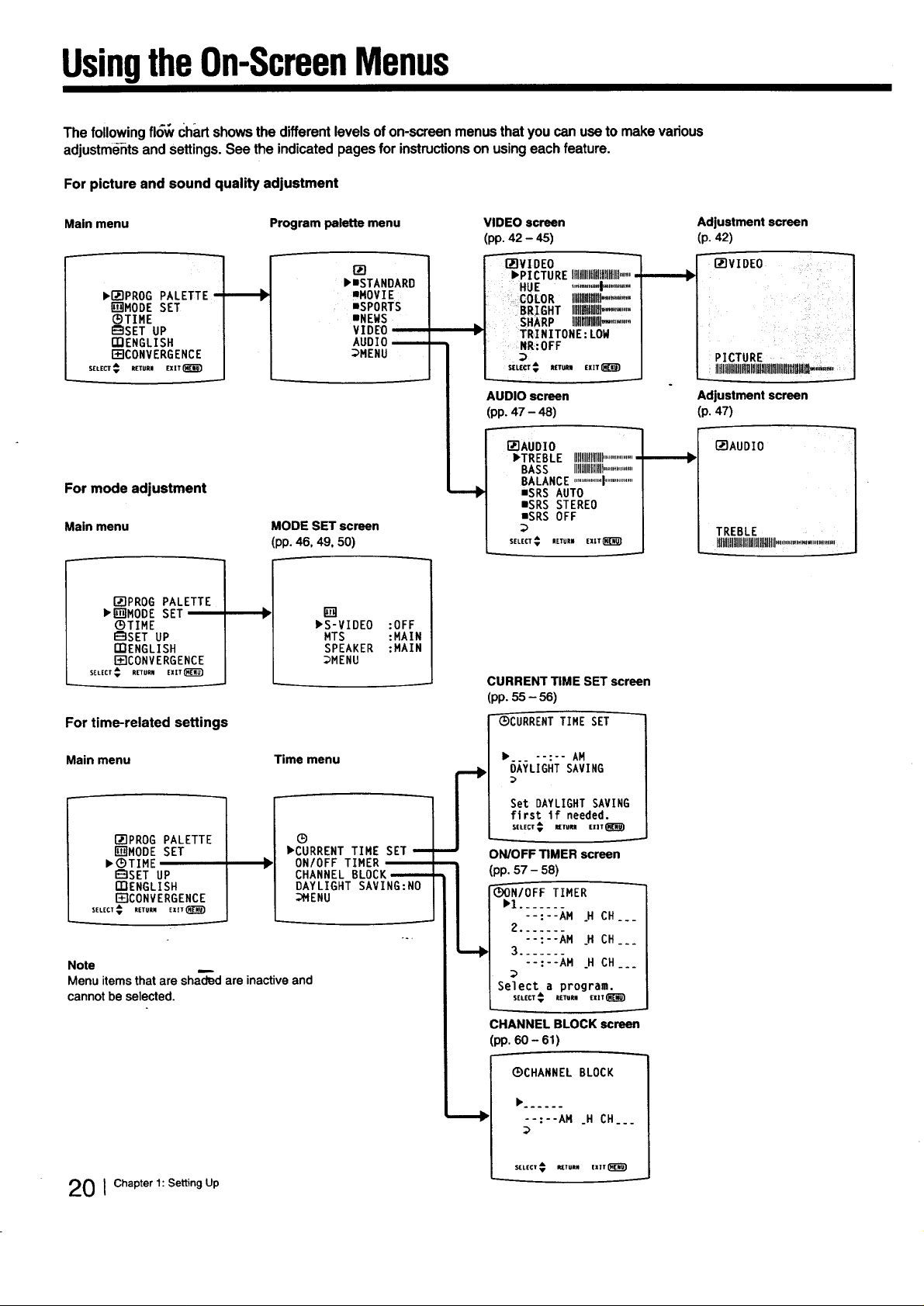
UsingtheOn-ScreenMenus
The followingfl6_tChartshowsthe differentlevelsofon-screenmenusthatyoucanusetomakevarious
adjustmentsand settings.See the indicatedpagesfor instructionsonusingeach feature.
For picture and sound quality adjustment
Main menu Program palette menu VIDEO screen
(pp. 42 - 45)
r'JqvIDEO
I_PICTURE It]lllllllfillltfllllttlll......
HUE "".........I'",......
,COLOR IIIIIMIII.........'....
BRIGHT Illll]flllillgl...........
SHARP IllWIII!ll_ ..........
TRINITONE: LOW
NR:0FF
st_(_¢ Rrrun Em_)
AUDIO screen
(pp. 47 - 48)
[]_]AUDIO
bTREBLE Illlllllllifllll................
BASS IIIIHlflillllll................
BALANCE...............|..............
mSRSAUTO
mSRSSTEREO
mSRSOFF
:>
SELECT€ RE_RR EX|T_
CURRENT TIME SET screen
(pp. 55 - 56)
"-_CURRENTTIME SET
I,r71PROG PALETTE
[]MODE SET
_TIME
_SET UP
[]]ENGLISH
I_qCONVERGENCE
SEtEC_A. R(TUR.EXZT_B_)
For mode adjustment
Main menu
D-IPROG PALETTE
_[]MODE SET
_)TIME
_SET UP
mENGLISH
F_ICONVERGENCE
SELECT_ RETURN EXIT_
For time-related settings
_mSTANDARD
mMOVIE
aSPORTS
mNEWS
VIDEO
AUDIO_
_MENU
MODE SET screen
(pp. 46, 49, 50)
[]
I,S-VIDEO
MTS
SPEAKER
_MENU
:OFF
:MAIN
:MAIN
Adjustment screen
(p. 42)
D-IVIDEO
PICTURE
iltlltllllllllllllllll!llllllllllllllllllllBl_,".-,
Adjustment screen
(p. 47)
I_IAUDIO
TREBLE
IIII!lllltlllllllllllllllltllill...........................
Main menu Time menu
ITIPROG PALETTE
[]MODE SET
•GTIME
I_]SET UP
{;I:]ENGLISH
I_-ICONVERGENCE
SELECT_ RETURN EXI¥(_)
Note
Menu items that are shaded are inactive and
cannot be selected.
®
_CURRENT TIME SET u
ONIOFF TIMER
CHANNEL BLOCK_
DAYLIGHT SAVING:NO
;_HENU
20 1Chapter 1: Setting Up
• .._ --:-- AM
OAYLIGHT SAVING
Set DAYLIGHT SAVING
first If needed.
SELECT _ UETURN EXIT _ I_._)
ON/OFF TIMER screen
(pp. 57 - 58)
_N/OFF TIMER
• 1.......
--:--AM .H CH.__
2 .......
--:--AM H CH__.
3 ........
--:--AM .H CH_..
Select a program.
SELECT _ lET=JUg EXIT
;HANNEL BLOCK screen
(pp. 60 - 61)
_CHANNEL BLOCK
--:--AM _H CH_._
$(LECT _ It(TURN EX]T
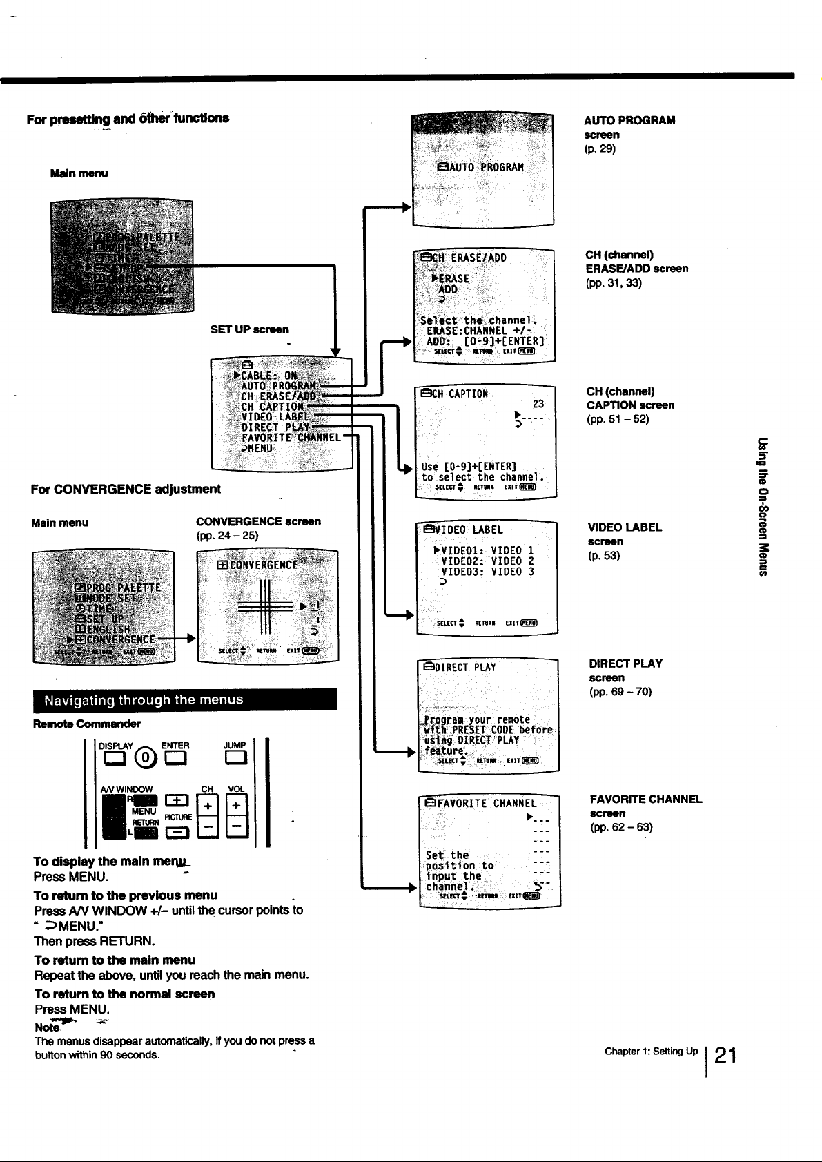
For presetting end 6(her functions
Main menu
SET UP screen
AUTO PROGRAM
screen
(p.29)
CH (channel)
ERASE/ADD screen
(pp. 31, 33)
For CONVERGENCE adjustment
Main menu CONVERGENCE screen
(pp. 24 - 25)
Remote Commander
JUMP
D_Y(_ ENTER
/VV WINDOW CH VOL
MENU
23
_IDEO LABEL
• VZOEm:VZOEOZ
VIDEO2: VIDEO 2
VIDE03: VIDEO 3
R|TUII EXIT_)
"_DI RECTPLAY "_-
_FAVORITE CHANNEL
•:..
CH (channel)
CAPTION screen
(pp. 51 - 52)
VIDEO LABEL
screen
(p.53)
DIRECT PLAY
screen
(pp. 69 - 70)
FAVORITE CHANNEL
screen
(pp. 62 - 63)
r--
o0
m
:1
lid
o
:l
OJ
O=
--j
CD
€
O_
To display the main mertlt_
Press MENU. °
To return to the previous menu
Press AN WINDOW +/- until the cursor points to
" :_ MENU."
Then press RETURN.
To retum to the main menu
Repeat the above, until you reach the main menu.
To return to the normal screen
Press MENU.
Note"_
The menusdisappearautomatically,ifyou do notpressa
buttonwithin90 seconds.
Set the "--
position to -"
tnput the """
chann_,, :
Chapter 1: Selting Up I21
UsingtheOn-ScreenMenus
F
MUTING SLEEP POWER
r--i r-3_
CH+ FREEZE WNIDE0 SWAP PiP
r_ r-I !_ !_ E3
CH- POSITION AUDIO OFF
0©®
®®®
®®®
r-!
AN WINDOW CH VOL
V'rR1-2-3 MDP 1_/ CABLEBO)
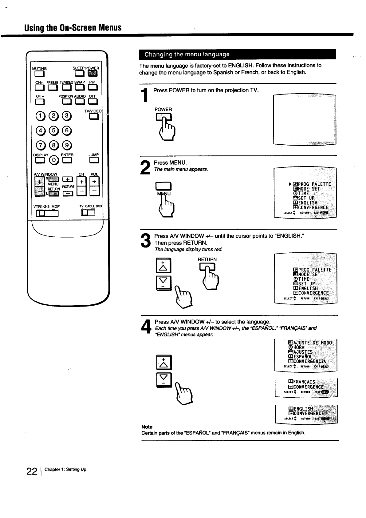
The menulanguageisfactory-setto ENGLISH.Followtheseinstructionsto
changethe menulanguageto SpanishorFrench,orbacktoEnglish,
Press POWER to tum on the projection TV.
1
POWER
Press MENU.Themainmenuappears.
_,I_'IPROG PALETI'E
IB'_MODE SET
Press AN WINDOW +/- until the cursor points to "ENGLISH."
Then press RETURN.
Thelanguagedisplayturnsred.
RETURN
22 1Chapter 1: Setting Up
J
Each time you press A/V WINDOW +/-, the "ESPAIVOL," "FRAN_AIS" and
Press AN WINDOW +/- to select the language.
=ENGLISH" menus appear.
%
Note
Certain parts of the "ESPAI_IOL" and "FRAN(_AIS" menus remain in English.
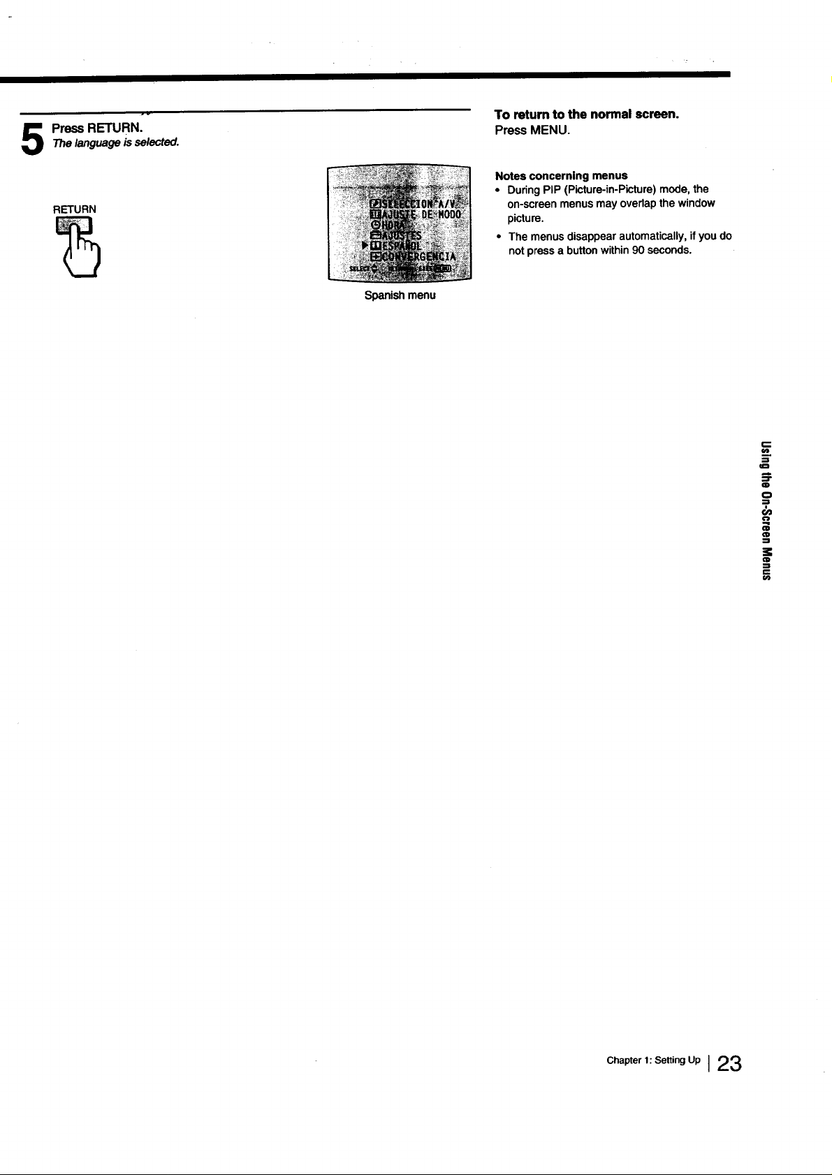
The language is selected.
Press RETURN.
RETURN
Spanish menu
To retum to the normal screen.
Press MENU.
Notes concerning menus
• During PIP (Picture-in-Picture) mode, the
on-screen menus may overlap the window
picture.
• The menus disappear automatically, if you do
not press a button within 90 seconds.
.=_
:=
a
,-b
:T
m
o
=
:l
:l
Chapter,;Se.,ogUpI 23
 Loading...