

Sony KP-FWS57M90 Service Manual
SERVICE MANUAL
MODEL COMMANDER DEST. CHASSIS NO.
CHASSIS
MODEL COMMANDER DEST. CHASSIS NO.
AX-1
PROJECTION TV
KP-FWS57M90
RM-1007 CH SCC-M14K-A
RM-1007 KP-FWS57M90
TV
M
E
M
O
R
Y
S
T
I
C
K
C
E
N
T
E
R
S
P
VIDEO
DRC-MF
HD/DVD
123
456
7809
JUMP
PROG
OPTION RESET
A/B
PROG
INDEX
MENU
V CENTERPALETTE
T
W
I
N
P
R
O
G
+
T
W
I
N
P
R
O
G
–
– 2 –
KP-FWS57M90
RM-1007
CAUTION
SHORT CIRCUIT THE ANODE OF HTE PICTURE TUBE
AND THE ANODE CAP TO THE METAL CHASSIS, CRT
SHIELD, OR CARBON PAINTED ON THE CRT, AFTER
REMOVING THE ANODE.
SAFETY-RELATED COMPONENT WARNING!!
COMPONENTS IDENTIFIED BY SHADING AND MARK
! ON THE SCHEMATIC DIAGRAMS, EXPLODED
VIEWS AND IN THE PARTS LIST ARE CRITICAL TO
SAFE OPERATION. REPLACE THESE COMPONENTS
WITH SONY PARTS WHOSE PART NUMBERS APPEAR AS SHOWN IN THIS MANUAL OR IN SUPPLEMENTS PUBLISHED BY SONY.
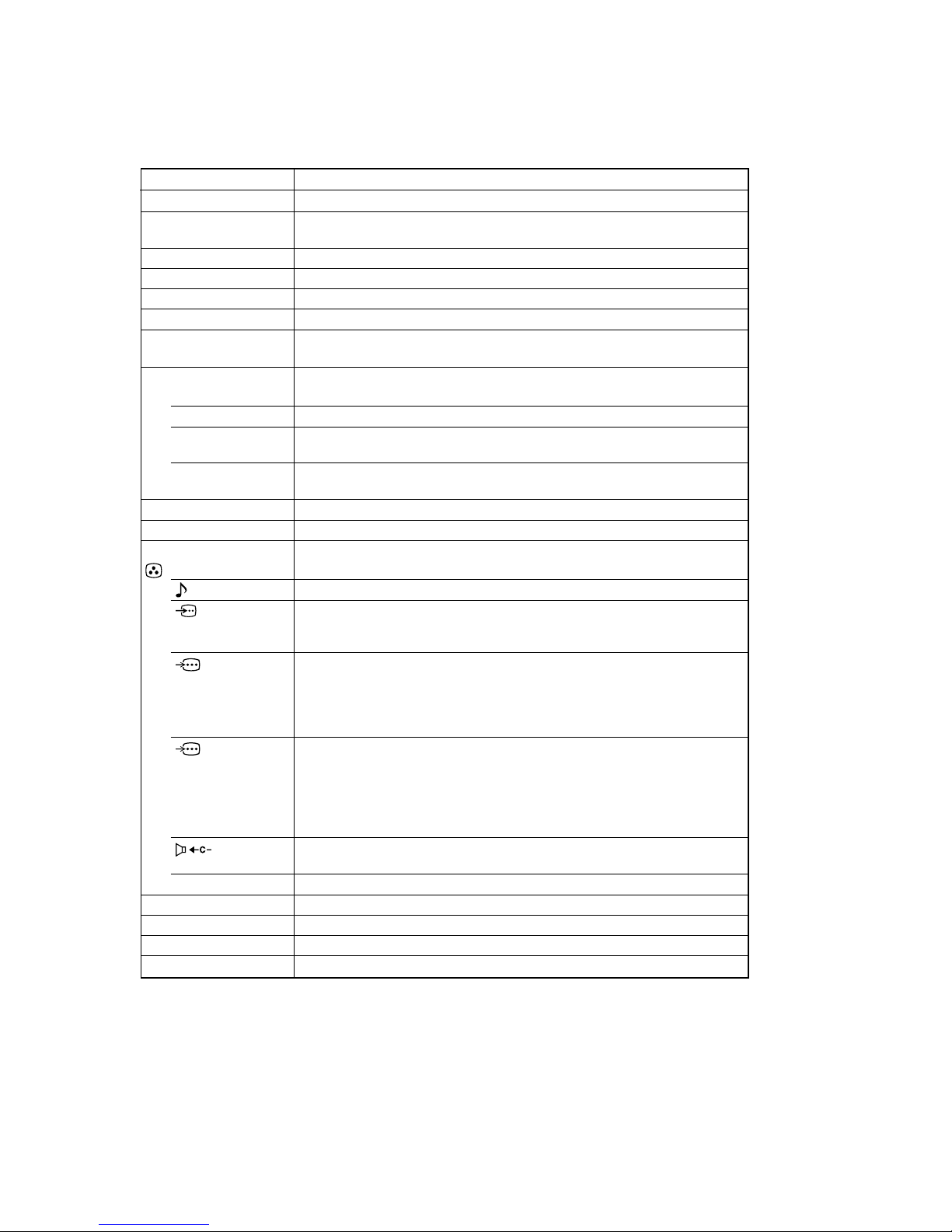
SPECIFICATIONS
Projection system
Picture tube
Projection lenses
Screen size
Television system
Color system
Stereo/Bilingual
system
Channel coverage
B/G
I
D/K
M
8(Antenna)
Audio output (Speaker)
Number of terminal
(Video)
(Audio)
(S Video)
(Component
Video)
(G/B/R/HD/
VD Video)
(Center
Speaker)
i (Headphones)
Power requirements
Power consumption (W)
Dimensions (w/h/d, mm)
Mass (kg)
KP-FWS57M90
3 picture tubes, 3 lenses, horizontal inline system
High performance, large-diameter highbrid lens F1.0
57 inches (144.8 cm)
D/K, I, B/G, M
PAL, PAL 60, SECAM, NTSC 4.43, NTSC 3.58
NICAM Stereo/Bilingual D/K, I, B/K
VHF : E2 to E12 / UHF : E21 to E69 / CATV : S01 to S03, S1 to S41
UHF : B21 to B68 / CATV : S01 to S03, S1 to S41
VHF : C1 to C12, R1 to R12 / UHF : C13 to C57, R21 to R60 / CATV : S01 to S03,
S1 to S41, Z1 to Z39
VHF : A2 to A13 / UHF : A14 to A79/CATV : A-8 to A-2, A to W+4,
W+6 to W+84
75-ohm external terminal
12W + 12W (7% distortion)
Input: 4 Output: 1 Phono jacks; 1 Vp-p, 75 ohms
Input: 6 Output: 1 Phono jacks; 500 mVrms
Input: 2 Y: 1 Vp-p, 75 ohms,
unbalanced, sync negative
C: 0.286 Vp-p, 75 ohms
Input: 2 Phono jacks
Y: 1 Vp-p, 75 ohms, sync negative
P
B/CB
: 0.7 Vp-p, 75 ohms
P
R/CR
: 0.7 Vp-p, 75 ohms
Audio: 500 mVrms
Input: 1 Phono jacks
G: 0.7 Vp-p, 75 ohms
B: 0.7 Vp-p, 75 ohms
R: 0.7 Vp-p, 75 ohms
HD: 0.7 Vp-p, 75 ohms
VD: 0.7 Vp-p, 75 ohms
Input:1 120 W max., 8 ohms
Output: 1 Stereo minijack
220 V AC, 50/60Hz
250 W
1360 × 1395 × 688
93 kg
Design and specifications are subject to change without notice.
7 inch high-brightnes monochorome tubes (6.3 raster size), with optical coupling
and liquid cooling system

– 3 –
KP-FWS57M31/FWS57M91
RM-1007
1. SELF DIAGNOSIS FUNCTION
1-1. DIAGNOSTIC TEST INDICATORS ............... 5
1-2. DISPLAY OF STANDBY/TIMER
LIGHT FLASH COUNT ................................... 6
1-3. STOPPING THE STANDBY/TIMER FLASH 6
1-4. SELF-DIAGNOSTIC SCREEN DISPLAY ...... 7
1-5. HANDLING OF SELF-DIAGNOSTIC
SCREEN DISPLAY ........................................... 7
1-6. SELF-DIAGNOSTIC CIRCUIT ........................ 8
2. DISASSEMBLY
2-1. REAR BOARD REMOVAL ............................. 9
2-2. MAIN BRACKET REMOVAL ......................... 9
2-3. SERVICE POSITION ........................................ 9
2-4. FRONT PANEL, BEZNET AND
MIRROR COVER REMOVAL ......................... 10
2-5. HA, HC AND HMG BOARDS REMOVAL .... 10
2-6. HB2 BOARD REMOVAL ................................. 11
2-7. TERMINAL BRACKET REMOVAL ............... 11
2-8. UG BOARD REMOVAL .................................. 12
2-9. BM, DS, MG AND MS2 BOARDS REMOVAL 12
2-10. A AND D BOARDS REMOVAL ..................... 13
2-11. PICTURE TUBE AND
PWB BLOCK REMOVAL ................................ 13
2-12. HIGH-VOLTAGE CABLE INSTALLATION
AND REMOVAL ............................................... 14
2-13. MECHASEAL .................................................... 14
3. SET-UP ADJUSTMENTS
3-1. SCREEN VOLTAGE ADJUSTMENT
(ROUGH ALIGNMENT) ................................. 15
3-2. SCREEN (G2) ADJUSTMENT
(FINE ADJUSTMENT) ..................................... 15
3-3. FOCUS ROUGH ADJUSTMENT .................... 15
3-4. DEFLECTION YOKE TILT ADJUSTMENT .. 15
3-5. 2-POLE and 4-POLE MAGNET
ADJUSTMENT .................................................. 16
3-5-1. Adjustment of 2-pole magnets ....................... 16
3-5-2. Green, Red, Blue adjustment of
4-pole magnets ............................................... 16
3-5-3. Blue left side dot adjustment of
2-pole Magnets ............................................... 16
3-6. BLUE DEFOCUS ADJUSTMENT ................... 16
3-7. GREEN, RED AND BLUE FOCUS
ADJUSTMENT .................................................. 16
3-7-1. Green, Red and Blue lens focus adjustment ... 16
3-7-2. Green and Red electrical focus adjustment .... 16
3-8. ADJUSTMENTS WITH COMMANDER ........ 17
3-8-1. How to Select Each Mode ............................. 17
3-8-2. How to Enter Service Mode .......................... 17
3-8-3. Method of Cancellation from Service Mode . 18
3-8-4. How to Adjustments ...................................... 18
TABLE OF CONTENTS
3-8-5. How to Write the Data ................................... 18
3-8-6. Memory Write Confirmation Method ........... 18
3-9. SERVICE LIST ..................................................... 19
3-10. REGISTRATION ADJUSTMENT ................... 68
3-10-1. ADJUSTME FLOW ...................................... 68
3-10-2. Setup for Adjustment ..................................... 68
3-10-3. Method of Main Deflection Adjustment ....... 68
3-10-4. Operation Method for
Projector Engine (PJE) Mode ........................ 69
3-10-5. Method of Projector Engine Adjustment
(Sub Deflection Adjustment) ......................... 70
3-11. AUTO CONVERGENCE SETTING ................ 74
3-12. BLUE OFFSET ADJUSTMENT ....................... 74
3-13. WHITE BALANCE ADJUSTMENT ................ 74
3-14. AUTO CONVERGENCE ERROR CODE LIST 75
4. ADJUSTMENT
4-1. HV REGULATION ADJUSTMENT (D Board) 77
4-2. +B MAX VOLTAGE CONFIRMATION ......... 77
4-3. +B OVP CONFIRMATION .............................. 77
5. ELECTRICAL ADJUSTMENTS
5-1. PICTURE QUALITY ADJUSTMENT ............. 79
5-1-1. Preparation ..................................................... 79
5-1-2. NTSC Video Input (Main Picture) ................ 80
5-1-3. NTSC RF Input (Main Picture) ..................... 80
5-1-4. NTSC Video Input (Sub Picture) .................. 81
5-1-5. NTSC RF Input (Sub Picture) ....................... 82
5-1-6. PAL Video Input (MainPicture) .................... 82
5-1-7. PAL RF Input (MainPicture) ......................... 83
5-1-8. PAL Video Input (Sub Picture) ..................... 83
5-1-9. PAL RF Input (Sub Picture) .......................... 84
6. DIAGRAMS
6-1. BLOCK DIAGRAMS ........................................ 85
(1) A (1/2), D (1/2) AND HC BOARDS
BLOCK DIAGRAMS .................................... 85
(2) A (2/2) BOARD BLOCK DIAGRAM .......... 87
(3) D (2/2) BOARD BLOCK DIAGRAM .......... 89
(4) AD AND SR BOARDS
BLOCK DIAGRAMS .................................... 91
(5) BM BOARD BLOCK DIAGRAM ............... 93
(6) DS BOARD BLOCK DIAGRAM................. 95
(7) HA, HB2 AND HMG BOARDS
BLOCK DIAGRAMS .................................... 97
(8) MG (1/2) BOARD BLOCK DIAGRAM ...... 99
(9) MG (2/2), CR, CG, CB AND VM
BOARDS BLOCK DIAGRAMS .................. 101
(10) MS2 BOARD BLOCK DIAGRAM .............. 103
(11) UG BOARD BLOCK DIAGRAM ................ 105
6-2. FRAME SCHEMATIC DIAGRAM .................. 107
6-3. CIRCUIT BOARDS LOCATION ..................... 109
Section Title PageSection Title Page

– 4 –
KP-FW51M90
RM-1015
6-4. SCHEMATIC DIAGRAMS AND
PRINTED WIRING BOARDS ........................ 110
(1) Schematic Diagram of A Board .................... 111
(2) Schematic Diagram of AD Board.................. 119
(3) Schematic Diagram of BM Board ................. 123
(4) Schematic Diagram of CR Board .................. 133
(5) Schematic Diagram of CB Board .................. 135
(6) Schematic Diagram of CG Board .................. 137
(7) Schematic Diagram of D Board .................... 139
(8) Schematic Diagram of DS Board .................. 147
(9) Schematic Diagram of HA and HB2 Boards 151
(10) Schematic Diagram of HC and HMG Boards 153
(11) Schematic Diagrams of MG Board ............... 155
(12) Schematic Diagrams of MS2 Board .............. 163
(13) Schematic Diagram of SR and VM Boards .. 171
6-5. SEMICONDUCTORS ....................................... 179
7. EXPLODED VIEWS
7-1. FRONT PANEL BLOCK .................................. 185
7-2. CABINET BLOCK ............................................ 186
7-3. BEZENET AND MIRROR COVER BLOCK .. 187
7-4. MAIN BRACKET AND PICTURE
TUBE BLOCK ................................................... 188
8. ELECTRICAL PARTS LIST ....................... 189
Section Title PageSection Title Page

– 5 –
KP-FWS57M90
RM-1007
SECTION 1
SELF DIAGNOSIS FUNCTION
The unit in this manual contain a self-diagnostic function. If an error occurs, the STANDBY/TIMER LED will automatically begin to
flash.
The number of times the LED flashes translates to a probable source of the problem. A definition of the STANDBY/TIMER LED flash
indicators is listed in the instruction manual for the user's knowledge and reference. If an error symptom cannot be reproduced, the remote
commander can be used to review the failure occurrence data stored in memory to reveal past problems and how often these problems
occur.
1-1. DIAGNOSTIC TEST INDICATORS
When an error occurs, the STANDBY/TIMER LED will flash a set number of times to indicate the possible cause of the problem. If there
is more than one error, the LED will identify the first of the problem areas.
Result for all of the following diagnostic items are displayed on screen. If the screen displays a “0”, no error has occurred .
• Power does not
turn on
• +B overcurrent
(OCP)
• +B overvoltage
(OVP)
• Vertical deflection
stopped
• White balance
failure
(not balanced)
•
LOW B down***
• Horizontal
deflection stopped
• Audio Protection
• Zero crossing
detector
• HV protection
• Power does not come on.
• No power is supplied to the PJ.
• AC power supply is faulty.
• Power does not come on.
• Load on power line is shorted.
• Has entered standby mode.
• Has entered standby mode after
horizontal raster.
• Vertical deflection pulse is
stopped.
• Power line is shorted or power.
• No raster is generated.
• CRT cathode current detection
reference pulse output is small.
• No picture.
• No picture.
• No picture.
•No picture.
• No picture.
Item 2:1
or more than 1
Item 3:1
or more than 1
Item 4:1
or more than 1
Item 5:1
or more than 1
Item 6:1
or more than 1
Item 7:1
or more than 1
Item 8:1
or more than 1
Item 9:1
or more than 1
Item 10:1
or more than 1
No. of times
STANDBY/TIMER
LED flashes
Symptoms
Diagnostic
Item
Description
Self-diagnostic
display/
Diagnostic result
Probable Cause Location
Does not light
2 times
3 times
4 times
5 times
6 times
7 times
8 times
9 times
10 times
• Power cord is not plugged in.
• Fuse (F6000) is burned out.
(A board)
• H. OUT(Q5001) is shorted.
• +B PWM(Q5201) is shorted.
(D board)
• IC6503 is faulty. (D board)
• 15V is not supplied. (D board)
• IC5101 is faulty. (D baord)
• Video
OUT(IC9101,IC9201,IC9301) is
faulty. (CR,CG,CB board)
• CRT drive (IC0401) is faulty. (MG
board)
• G2 is impropenrly adjustd.**
• +5V line is overloaded.
(A, BM, MG boards)
• +5V line is shorted.
(A, BM, MG boards)
• IC6201is faulty. (A board)
• Q5006 is broken. (D board)
• IC0401 is faulty. (MG board).
• + or - 22V audio supply is not
present - Check PS2001 &
PS2000
• D6166 or D6114 is open.
(A board)
• Q8014 or Q6013 have shorted
replace along with R8051 on D
board.
• IC8005 is damaged. (D board)
* If a +B overcurrent is detected, stoppage of the vertical detection is detected simultaneously. The symptom that is
diagnosed first by the microcontroller is displayed on the screen.
** Refer to screen (G2) adjustment (fine adjustment) in section 2 of this manual.
*** Is STNDBY/TIMER LED flashes six (6) times, unplug the unit and wait 10 seconds before performing the sdjustment.
– 6 –
KP-FWS57M90
RM-1007
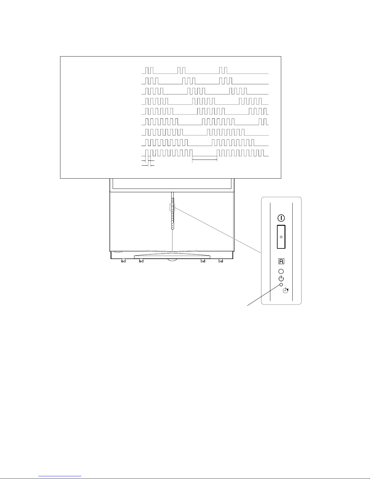
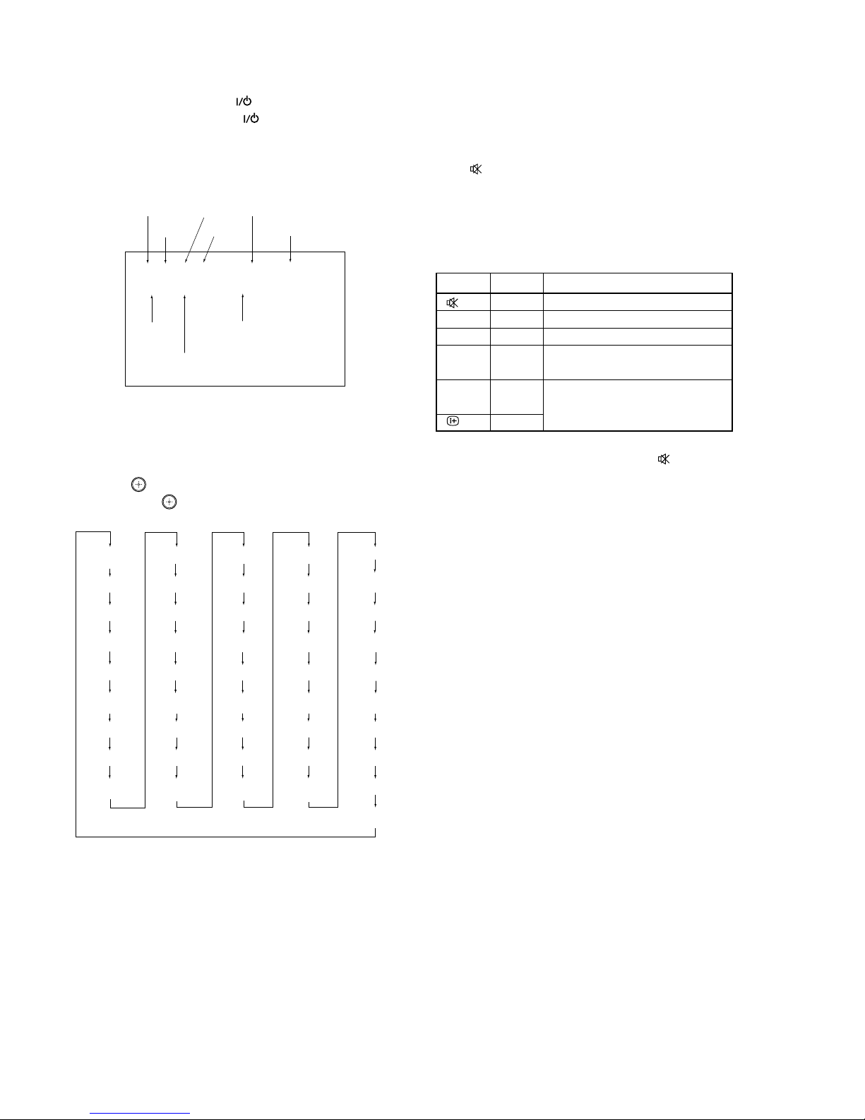
1-2. DISPLAY OF STANDBY/TIMER LIGHT FLASH COUNT
1-3. STOPPING THE STANDBY/TIMER FLASH
Turn off the power switch on the TV main unit or unplug the power cord from the outlet to stop the STANDBY/TIMER lamp from
flashing.
LED OFF 3 sec
LED ON 0.3 sec.
LED OFF 0.3 sec.
4 tims
5 tims
6 tims
7 tims
8 tims
9 tims
10 tims
HV protection
2 tims
3 tims
Audio protection
Zero crossing detector
Low +B OVP/OCP
Horiz. deflection stopped
Vert. deflection stopped
White balance failure
+B Overcurrent
Low +B Overvoltage
Flash count
Diagnostic items
* One flash counts is not used for silf-diagnostic.
STANDBY/TIMER
lamp
– 7 –
KP-FWS57M90
RM-1007
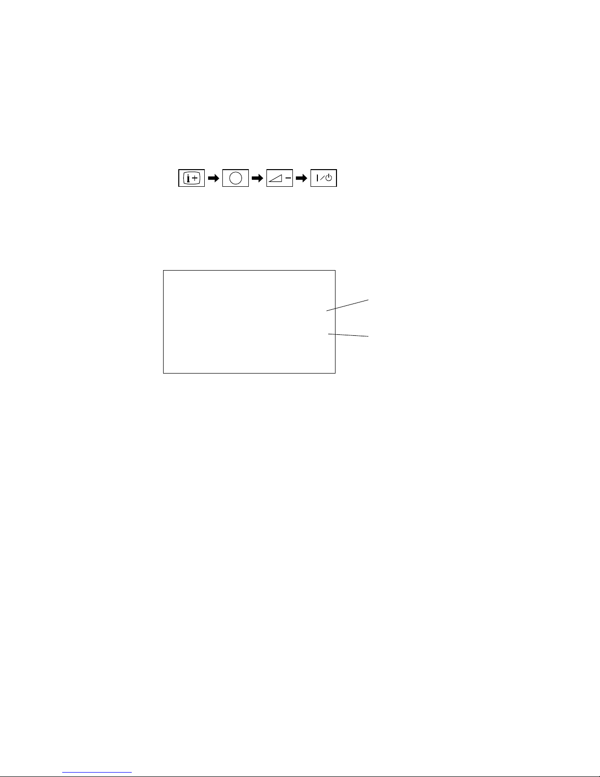
1-4. SELF-DIAGNOSTIC SCREEN DISPLAY
For errors with symptoms such as “power sometimes shuts off” or “screen sometimes goes out” that cannot be confirmed, it is possible to
bring up past occurrences of failure for confirmation on the screen:
[To Bring Up Screen Test]
In standby mode, press buttons on the remote commander sequentially in rapid succession as shown below:
Self-Diagnosis screen display
1-5. HANDLING OF SELF-DIAGNOSTIC SCREEN DISPLAY
5
(DIGIT 5) (VOLUME –) (POWER)ON SCREEN
DISPLAY
()
*
* : Note that this differs from entering the service mode (volume +)
Since the diagnostic results displayed on the screen are not automatically cleared, always check the self-diagnostic screen
After you have completed the repairs, clear the result display to “0”.
[Clearing the result display]
To clear the result display to “0”, press button on the remote commander sequentially as shown below when the diagnostic screen is being
displayed.
[Quitting Self-diagnostic screen]
To quit the entire self-diagnostic screen, turn off the power switch on the remote commander or the main unit.
Press “8” button
(It will indicate “CLEAR” on the screen.)
Press “-” button
(The “CLEAR” display change to red color.)
,
SELF DIAGNOSTIC
2 OCP : 0
3 OVP : 0
4 V STOP: 0
5 AKB : 0
6 LOW-B : 0
7 H STOP : 0
8 A PRT : 1
9 Z DET : 0
10 HV PRT : 0
101 WDT : 0
102 WDT PF : 24
Number "1 "
means a fault was detected one
time only.
Number "0 "
means that no fault detected.
– 8 –
KP-FWS57M90
RM-1007
+B overcurrent (OCP) Occurs when excessive current flows through R6812.
The increase in voltage across Q6803 causes it to turn on which sends a high
signal to the micro.
+B overvoltage (OVP) IC6801 detects +B OVP condition and Q6802.
This sends a high signal to the micro and also shuts down the AC relay.
V-STOP Occurs when an absence of the vertical deflection pulse is detected by pin 56 of
IC0404 (MG board).
Power supply will shut down when waveform interval exceeds 2 seconds.
White balance failure If the RGB levels* do not balance within 2 seconds after the power is turned on,
this error will be detected by IC0401.
TV will stay on, but there will be no picture.
Low +B OCP/OVP Occurs when set 5V is out.
Horizontal deflection stopped Occurs when either :
1) a +B overcurrent is detected (Q6803), or
2) IC0401 (MG board) is damaged.
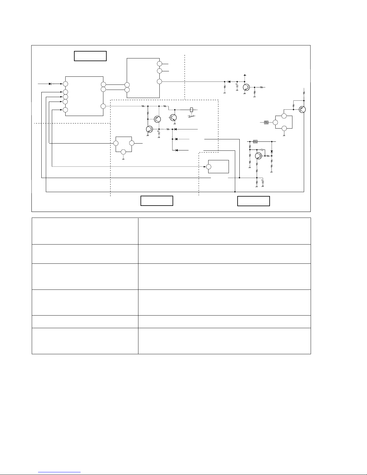
1-6. SELF-DIAGNOSTIC CIRCUIT
IC0001
MAIN MICRO
22
STBY-LED
5
OCP
6
OVP
53
SCL
52
SDA
AKB
24
CLKO
14
V PROT
56
87
LOW B ERR
33 HV PROT
AC RLY 36
DATO
13
HG PROT
57
2
1
3
1
< +15V
<
+B OCP
>
<
IK PROT2
>
<
+B OCP
>
<
+B OVP
>
2
3
1
< H PLS
Q6108
Q6102
Q6803
CRT
VDY-
+12V
Q5202
RY6000
<
P_SW(-)
IC6201
+B
>
IC8001
IC6801
+15V
<
Q6802
+B >
D6805
< +B
STBY-LED
Q6105
D6803
D6122
D6121
MG BOARD
A BOARD
D BOARD

– 9 –
KP-FWS57M90
RM-1007
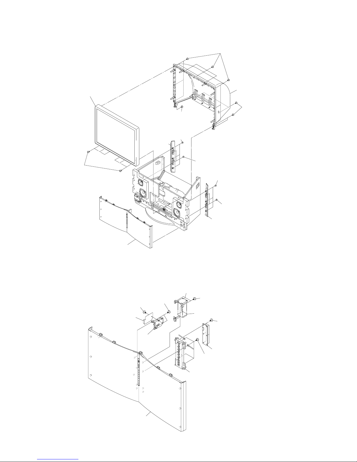
SECTION 2
DISASSEMBLY
2-1. REAR BOARD REMOVAL 2-2. MAIN BRACKET REMOVAL
2-3. SERVICE POSITION
2 COVERS
Cut them off with a plier or the like from chassis
assembly in case of checking printed circuit boards.
After checking, turn over the covers and secure them
with screws.
(screws 7-685-648-79 -BVTP 3X12)
1 Twelve screws
(Hexagon head)
2 Rear board
2 Thirteen screws
(BVTP 3X12)
1 Main bracket section
2 Two screws
(Hexagon head)
1 Optical shield
3 PWB block assy
– 10 –
KP-FWS57M90
RM-1007
2-4. FRONT PANEL, BEZNET AND MIRROR COVER REMOVAL
2-5. HA, HC AND HMG BOARDS REMOVAL
7 Speaker grile
3 Three screws
(BVTP 4x16)
2 Three screws
(BVTP 4x16)
6 Three screws
(BVTP 4x16)
8 Nine screws
(BVTP 4x16)
0 Mirror cover
1 Panel side (R)
9 Four screws
(Hexagon head)
9 Two screws
(Hexagon head)
qs Bezele assy
qa Six screws
(Hexagon head)
5 Two screws
(Hexagon head)
4 Panel side (L)
4 HMG board
8 Six screws
(BVTP 3x12)
Front panel assy
2 HM bracket
6 HC bracket
7 HC board
9 HA board
qa Control button (FW)
0 Four screws
(BVTP 3x12)
5 Two screws
(BVTP 3x12)
1 Two screws
(BVTP 3x12)
3 Screw
(BVTP 3x12)
– 11 –
KP-FWS57M90
RM-1007
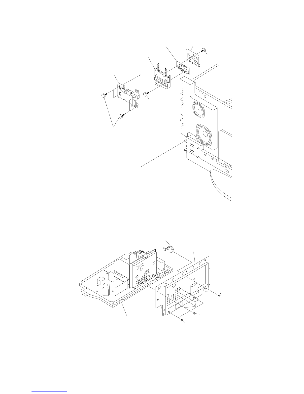
2-6. HB2 BOARD REMOVAL
5 Input terminal plate
3 Input terminal assy
2 Input terminal cover
7 HB2 board
6 Two screws
(BVTP 3x12)
4 Screw
(BVTP 3x12)
1 Four screws
(BVTP 4x12)
2-7. TERMINAL BRACKET REMOVAL
2 Four screws
(BVTP 3X12)
3 Screw
(PSW 3X8)
4 Terminal bracket
Main bracket section
1 Two screws
(BVTP 3X12)
RF splitter

– 12 –
KP-FWS57M90
RM-1007
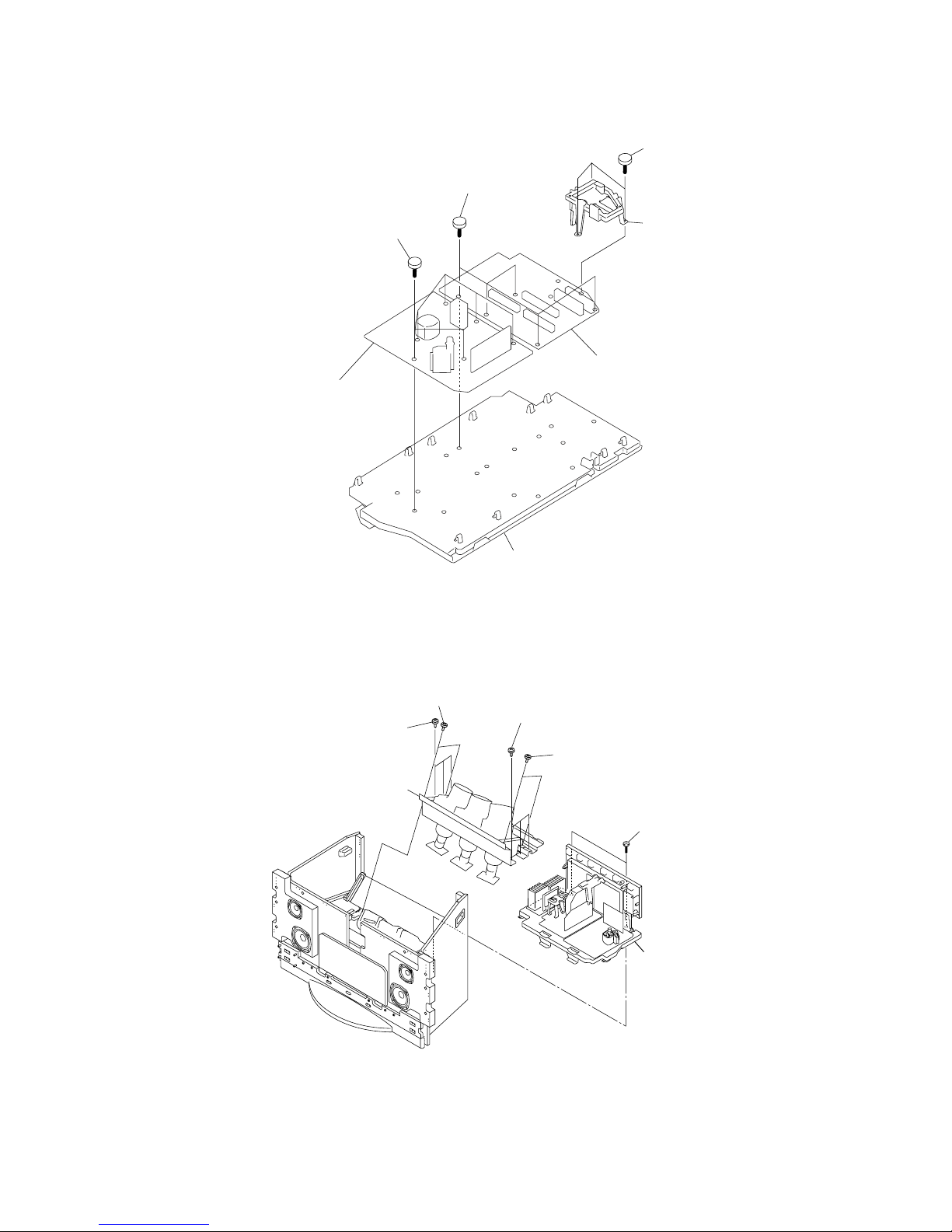
2-9. BM, DS, MG AND MS2 BOARDS REMOVAL
Main bracket section
2 BM board
1 MG Board
5 MS2 board
7 DS board
4 Three screw
(BVTP 3x12)
3 Shield case
6 Screw
(BVTP 3x12)
3 UG board
2 B bracket
Main bracket section
1 Two screws
(PSW 3x8)
2-8. UG BOARD REMOVAL
– 13 –
KP-FWS57M90
RM-1007
2-10. A AND D BOARDS REMOVAL
6 D board
4 A board
Main bracket section
3 Five screws
(BVTP 3x12)
5 Six screws
(BVTP 3x12)
2 G1 bracket
1 Three screws
(BVTP 3x12)
5 PWB block assy
3 Picture tube block assy
2 Three screws
(Hexagon head)
(4X20)
2 Three screws
(Hexagon head 4X20)
4 Two screws
(Hexagon head 4X20)
1 Two screws
(BVTP 4X16)
1 Two screws
(BVTP 4X16)
2-11. PICTURE TUBE AND PWB BLOCK REMOVAL
– 14 –
KP-FWS57M90
RM-1007
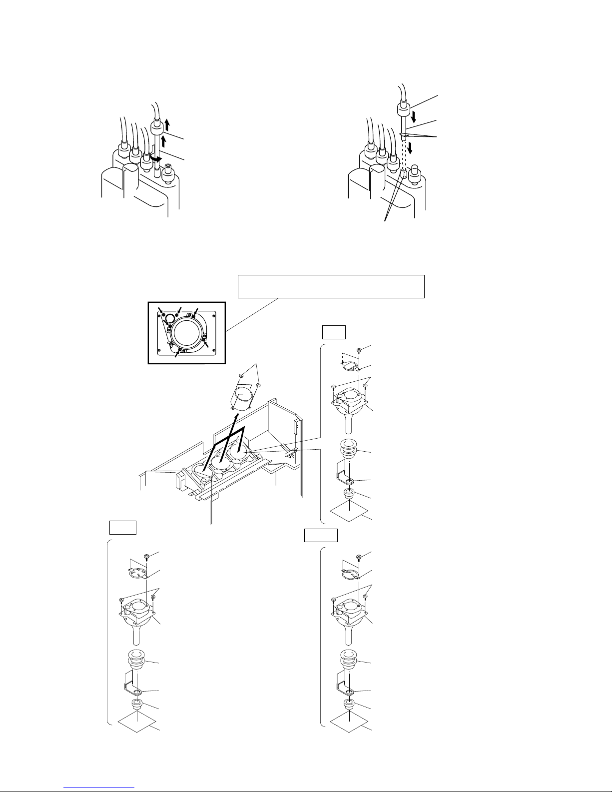
2-13. MECHASEAL
1 Four screws
(BVTP 4X16)
8 Two screws (BVTP 4X16)
6 Four screws
(BVTP 4X16)
Removing the arrow-marked screw is strictly inhibited.
If removed, it may cause liquid spill.
2 CR board
3 VMcoil assy
4 VM board
7 Mechaseal assy (R)
5 Deflection yoke
9 Shading (R) (Red only)
8 Screw (BVTP 4X16)
6 Four screws
(BVTP 4X16)
7 Mechaseal assy (G)
9 Shading (G) (Green only)
8 Screw (BVTP 4X16)
9 Shading (B) (Blue only)
6 Four screws
(BVTP 4X16)
7 Mechaseal assy (B)
BLUE
GREEN
RED
2 CR board
3 VMcoil assy
4 VM board
5 Deflection yoke
2 CR board
3 VMcoil assy
4 VM board
5 Deflection yoke
2-12. HIGH-VOLTAGE CABLE INSTALLATION AND REMOVAL
(1) Remover (2) Installation
1 Rubber cap
2 HV cable turn 90°
2 Rubber cap
1 HV cable
Hook
– 15 –
KP-FWS57M90
RM-1007
Fig. 3-6
SECTION 3
SET-UP ADJUSTMENTS
3-1. SCREEN VOLTAGE ADJUSTMENT
(ROUGH ALIGNMENT)
1. Receive the Monoscope signal.
2. Set 50% BRIGHTNESS and minimum PICTURE.
3. Turn the red VR on the focus pack all the way to the left and
then gradually turn it to the right until the point where you can
see the retrace line.
4. Next gradually turn it to the left to the position where the retrace line disappears.
3-2. SCREEN (G2) ADJUSTMENT
(FINE ADJUSTMENT)
1. Turn on the power of the set.
2. Select VIDEO1 and make no signal input.
3. Supply DC (177.5 ± 0.5V) from external power supply to KR
(Fig.3-2).
3. Turn red of G2 VR clockwise, then retrace line appear.
4. Turn G2 VR counterclockwise and set retrace line just disappear (Fig.3-3).
5. Add DC voltage DC (174 ± 0.5V) to KR.
6. Confirm if retrace can be seen.
7. Adjust green and blue at the same method.
3-3. FOCUS ROUGH ADJUSTMENT
1. Connect VIDEO-1 terminal.
2. Receive video dot hatch pattern.
3. Use lens-cover to red and blue.
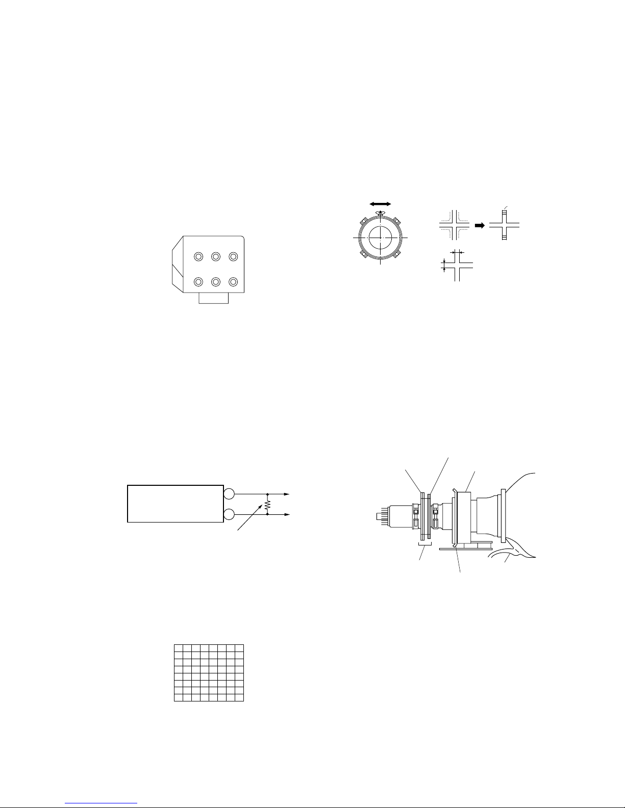
VMcoil Assy
Make sure deflection yoke is
touching CRT closely.
2-pole magnet
4-pole magnet
Deflection yoke
Anode cap
Centering magnet
Fig. 3-1
4. Adjust electric focus (roughly).
5. Rotate the green lens and adjust to obtain the best lens focus.
6. Rotate the green focus volume on the focus pack and adjust to
obtain best electrical focus.
7. If focus is not good, repeat 4 process.
8. Repeat above process for red and blue lenses and electric focus.
9. Fix lens screw.
3-4. DEFLECTION YOKE TILT ADJUSTMENT
1. Receive the Monoscope signal.
2. Place the caps on the red and blue lens so that only the green
color.
3. Loosen the deflection yoke setscrew and align the tilt of the
Deflection yoke so that the bars at the center of the
monoscope pattern are horizontal.
4. After aligning the deflection yoke, fasten it securely to the
funnel-shaped portion of the CRT.
5. The tilt of the deflection yoke for red and blue is aligned the
same as was done for green.
SCREEN
B
RG
FOCUS
Focus Pack
BRG
+
–
Power
Supply
Dummy Resister
3k ohm 20W
Fig. 3-2
Fig. 3-3
Test signal
Fig. 3-5
Lens
Fig. 3-4
Minimize both A and B.
A
B
Scanning line visible.
– 16 –
KP-FWS57M90
RM-1007
3-6. BLUE DEFOCUS ADJUSTMENT
1. Receive 1080i/50Hz dot signal from HD/DVD 1 terminal.
2. Set “Hi Fine” and PICTURE 100%, other 50% and white balance “COOL” (VM OFF).
3. Blue 4 pole : make round in the center of screen.
4. Confirm that center dot focus is adjusted in focus (Fig.3-12a).
5. Adjust blue electrical focus to make the left side spot nearly
round by minimizing width and height (Slight overfocus is
OK) (Fig.3-12b).
6. Confirm that the green to blue spot size is within spec.
Blue center dot height shall be ≤1.2 times the green dot heght.
7. Return making condition data to orignal data.
3-7. GREEN, RED AND BLUE FOCUS
ADJUSTMENT
3-7-1. Green, Red and Blue lens focus
adjustment
1. Input a cross hatch signal into VIDEO 1 (composite video input).
2. Place a lens cover over red and blue lenses and project only
green.
3. Rotate the green lens and adjust to obtain the best lens focus at
the center area.
4. Fix lens screw.
5. Repeat above process for red and blue.
3-7-2. Green and Red electrical focus adjustment
1. Input a cross-hatch signal into VIDEO 1.
2. Project only Green.
3. Rotate the green focus volume on the focus pack and adjust to
obtain the best focus at the center screen.
4. Repeat above process for red.
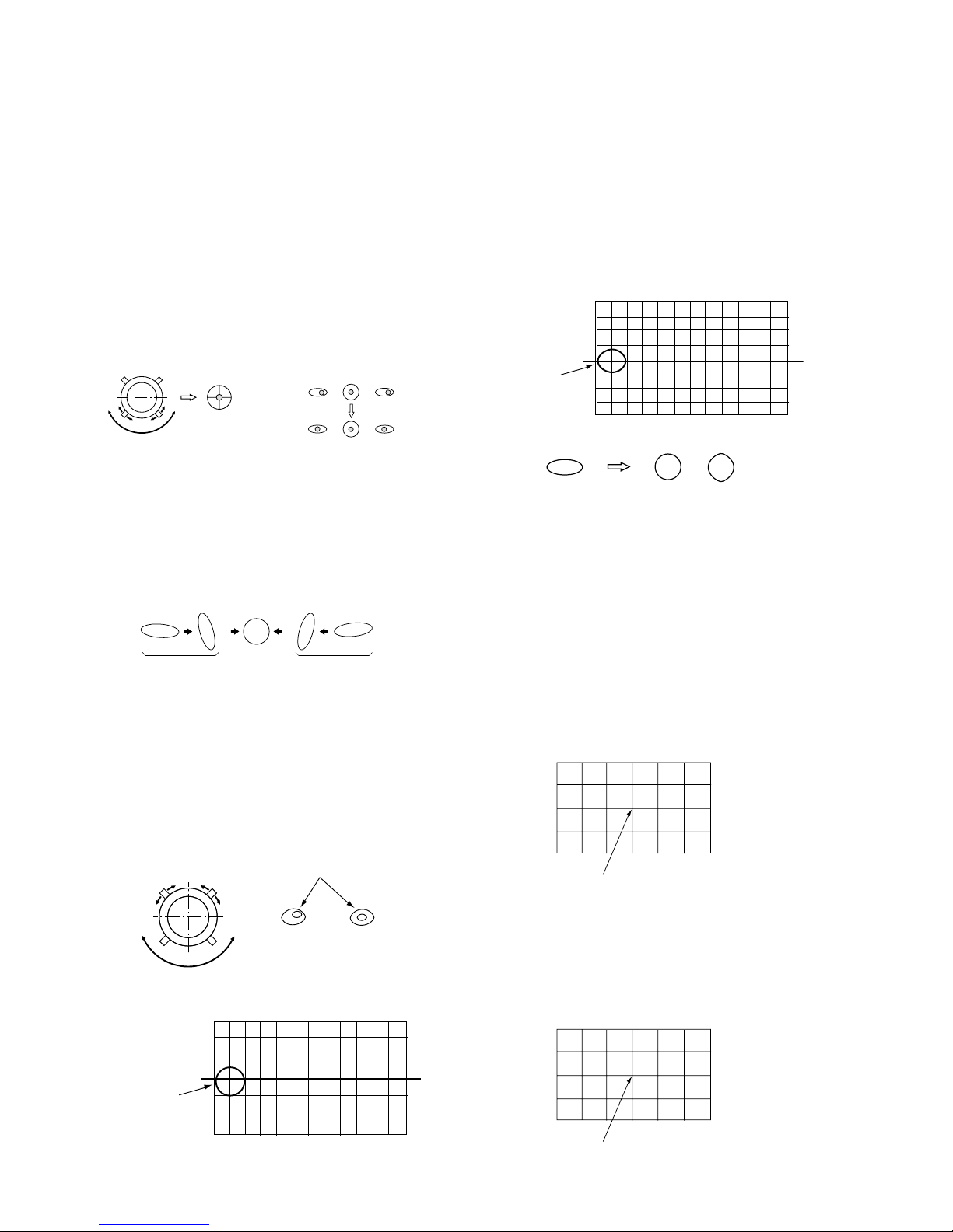
3-5. 2-POLE and 4-POLE MAGNET ADJUST-
MENT
3-5-1. Adjustment of 2-pole magnets
1. Receive the Dot signal (1080i/50Hz) from HD/DVD 1 terminal.
2. Place the caps on the red and blue lens so that only the green
color is shown.
3. Turn the green focus volume of focus pack counter-clockwise, so that diameter of the dot become large.
4. Adjust the 2-pole magnet, counter-clockwise and clockwise
center of the dot doesn't move (Use focus volume).
5. Center position is changed by 2-pole magnet adjustment.
So, center magnet adjustment and 2-pole magnet adjustment
are needed tracking adjustment.
6. Repeat same adjustment method for red and blue.
3-5-2. Green, Red, Blue adjustment of 4-pole
magnets
1. Turn Grenn focus volume of focus pack clockwise.
2. By using 4 pole magnets make the spot size round.
3. Repeat for red and blue.
4. Turn focus pack counter-clockwise and “Just Focus” red,
green and blue.
3-5-3. Blue left side dot adjustment of 2-pole
Magnets
1. Turn blue focus volume of focus pack counter-clockwise, so
that diameter of the dot becomes large, and can see bright
core position.
2. Pay attentio to left side dot of the screen (Fig.3-10).
3. Adjustment 2 pole magnet, so that bright core position of dot
become center position of dot (Fig.3-11).
Use the center dot
NG
OK
Left-end dot
(BLUE)
Right-end dot
(BLUE)
Fig. 3-7 Fig. 3-8
Fig. 3-12a
Fig. 3-12b
Blue 2 Defocus
Adjustment Position
OK
Fig. 3-13
Adjust Point center
Fig. 3-14
Adjust Point
Fig. 3-9
OKNG
NG
Use the center dot
Bright Core
Fig. 3-10
Blue 2 Pole magnet
Adjustment Position
Fig. 3-11
– 17 –
KP-FWS57M90
RM-1007
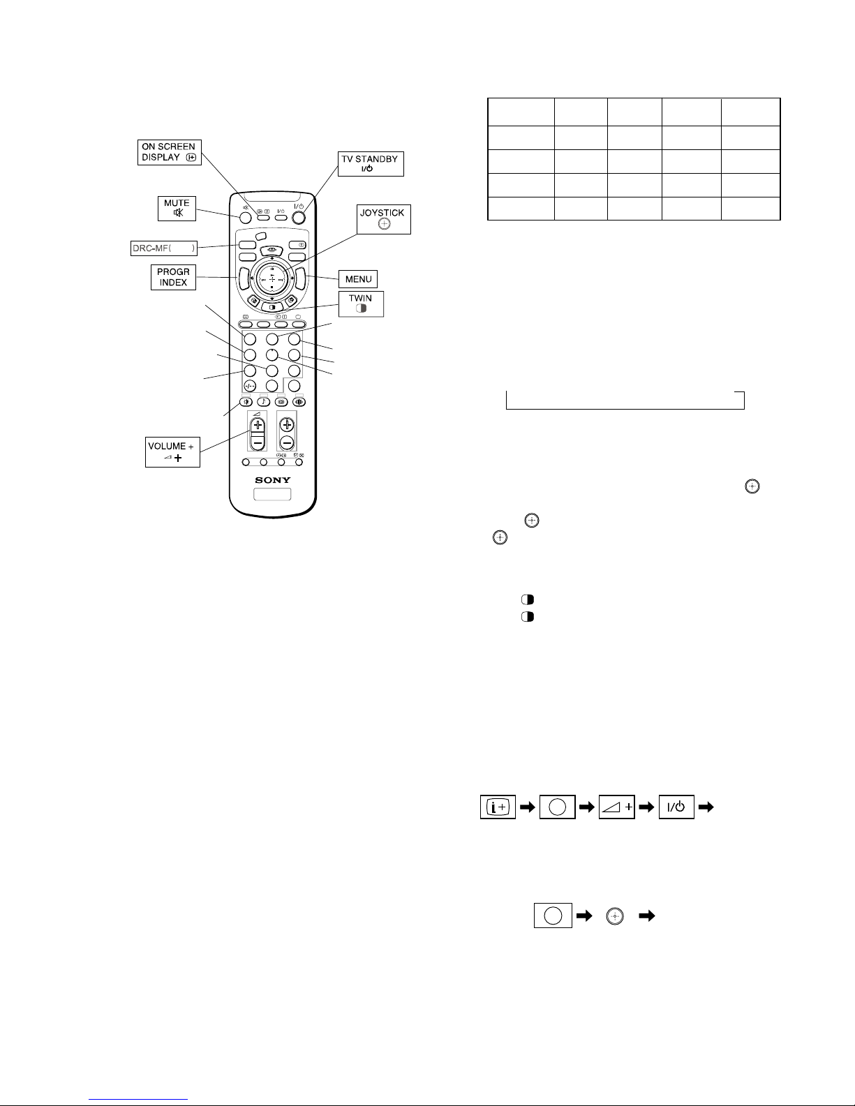
3-8-1. How to Select Each Mode
1. Selection of Mode Between 50 Hz and 60 Hz
50 Hz : Enter the PAL signal.
60 Hz : Enter the NTSC signal.
WIDE 60 Hz : Enter the NTSC signal MENU WIDE ON.
WIDE 50 Hz : Enter the PAL signal MENU WIDE ON.
2. Selection of DRC Mode
1) Press “DRC-MF (blue)” button on the commander, repeatedly until displays the mode that you want to select on the
screen.
→ DRC1250 → DRC100 → PROGRESSIV
Note : The DRC-MF mode is not selectable when using the
“PROGRAM INDEX” or “TWIN” mode is turned “ON”.
3. Selection of WIDE mode
1) Press “MENU” button on the commander and move “
” up
or down to enter the “FEATURE” b “WIDE MODE”.
2) Move “
” up or down to select “ON” or “OFF”, and push
“
(ENTER)” button.
3) Press “MENU” button to return to normal screen.
4. Selection of TWIN mode
1) Press “
(TWIN)” button on the commander.
2) Press “
(TWIN)” button again to return to normal screen.
5. Selection of INDEX mode
1) Press “PROGR INDEX” button on the commander.
2) Press “PROGR INDEX” button again to return to normal
screen.
3-8-2. How to Enter Service Mode
1. Turn on the main power switch to place this set in standby
mode (LED will light in red.).
2. Press the buttons on the commander as follows, and enter service mode.
3. After entering service mode, reset current aadjustment data.
Then turn off the power switch.
4. Turn on the main power switch and enter mode again as step 2
above.
TV
M
E
M
O
R
Y
S
T
I
C
K
C
E
N
T
E
R
S
P
VIDEO
DRC-MF
HD/DVD
123
456
7809
JUMP
PROG
OPTION RESET
A/B
PROG
INDEX
MENU
V CENTERPALETTE
T
W
I
N
P
R
O
G
+
T
W
I
N
P
R
O
G
–
Copy PAL data
to NTSC
blue
Adjustment item
up
Adjustment item
down
User control goes
to the standard state
Write data to NVM
Read data from
NVM
Change
the PICTUER MODE
Initialize data
(Not stored)
Data down
Data up
Copy data to all
mode
Up : Category up
Down : Category down
Push : Enter
Enter the
“Service mode”
5
(DIGIT 5) (VOLUME +)ON SCREEN
DISPLAY
()
TV
STANDBY
()
Enter the
“Reset”
8
(DIGIT 8)
(ENTER)
RM-1007
3-8. ADJUSTMENTS WITH COMMANDER
Service adjustment to this model can performed with the supplied
remote commander RM-1007.
50 Hz 60 Hz
WIDE 60 Hz WIDE 50 Hz
(PAL) (NTSC) (NTSC) (PAL)
DRC1250 aa a a
DRC100 aa a a
TWIN aa
XX
INDEX aa
XX
– 18 –
KP-FWS57M90
RM-1007
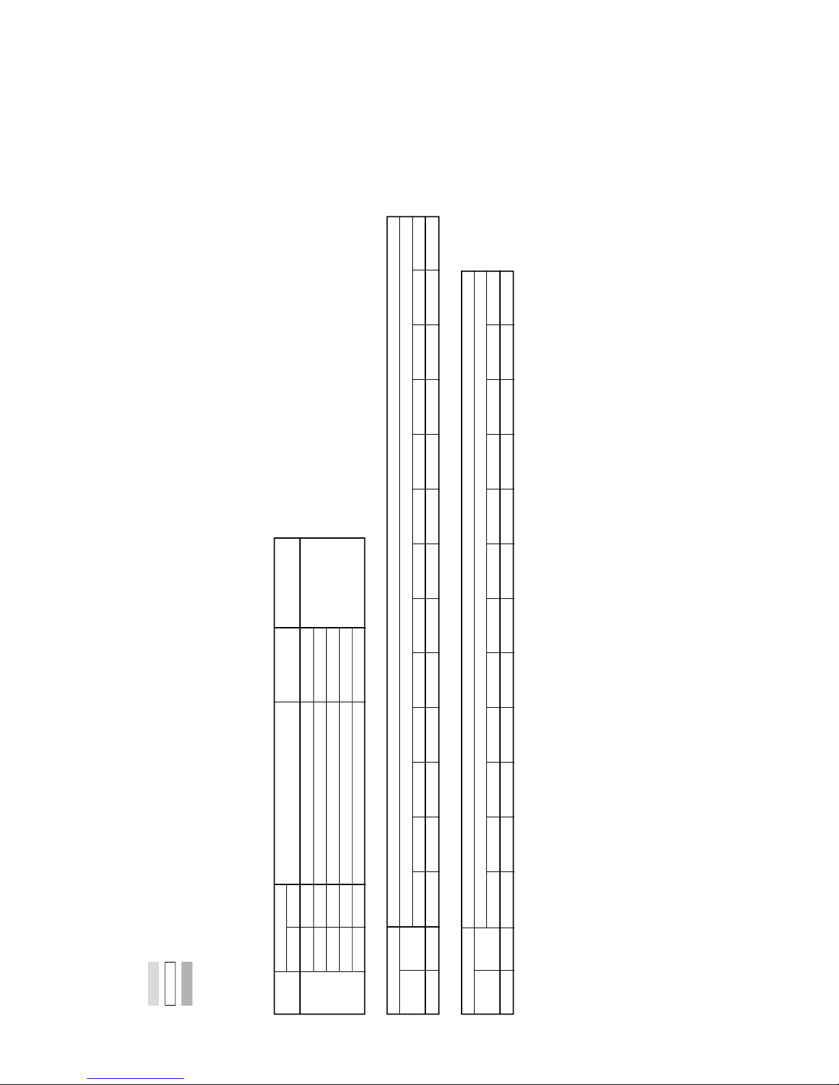
PIC
SOU
DRCV
LUMA
YCTM
YCTS
YCTC
MCP
MID1
VSW
MID3
MID2
PFOP
* : When it moves from PJE to other categrys,
repeat 1 or 4 button and press it.
PFID
AP
GRN
PJE*
DDEV
COLR
CLTY
DEF1
DEF2
CRNR
RNR
MSMO
3CM
POWR
GUID
MIDE
CCPM
COMB
DEF3
DEF4
DEF5
BNR
SNNR
AWID
OSDP
ASEL
VSEL
OPM
OPB
SRV
OSD
MSP
TEXT
3-8-5. How to Write the Data
1. Set in the service mode.
2. Press “1” or “1” button on the commander, select the adjustment item, and press “3” or “6” button to change the
data.
3. Press “
(MUTE)” button on the commander and it will indi-
cate “WRITE” on the screen.
4. Press “-” button on the commander to write into memory (The
“WRITE” display will be changed to red color while execut-
ing, and back to “SERVICE”.).
Note : Before changing to other modes, press “
(MUTE)” +
“-” buttons on the commander to write the data.
(Omission of this operation causes the data to be returned
to the data before adjustment.)
: Confirm the adjustment mode before writing data for data
values because to vary in each adjustment mode.
: The adjustment item that there are no relations in the ad-
justment is not to change data values because all items are
written in each adjustment mode.
3-8-6. Memory Write Confirmation Method
1. After adjustment, turn off the AC main power switch off.
2. Turn the power switch ON and set in service mode.
3. Call the adjustment items again to confirm adjustments were
made.
3-8-3. Method of Cancellation from Service Mode
1. Set the standby mode (Press “ (TV STANDBY)” button on
the commander), then press “
(TV STANDBY)” button
again, hereupon it becomes TV mode.
3-8-4. How to Adjustments
1. Set in the service mode, the following screen will appear.
2. Press “1” or “4” button on the commander to select the ad-
justment item.
3. Press “3” or “6” button on the commander to change the
adjustment data.
4. Move “
” up or down to select the adjustment category.
When move “
” up (category up), service mode changes in
the order as shown below.
OSD 0 OSV 32 SERVICE 60 480IL
000Q 3.1M 0010 0000 20 00 00 0000
Category Name
Item Name
Mode
Item No.
Suffix No.
Total Power On time
(Hours)
Software
Version
Data
50 : PAL, SECAM
60 : NTSC
Button Mode Description
+ - WRITE Writes data to NVM.
7 + - READ Reads data from NVM.
8 + - NORMAL All user control goes to the standard.
5 + - INITIAL Service data initialization. Not stored.
(Be sure not to use usually)
2 + - COPY Do not operate with a remote
commander.
+ - WRT5060 (The data vary with among mode.)
Commander Function (Except PJE mode)
– 19 –
KP-FWS57M90
RM-1007
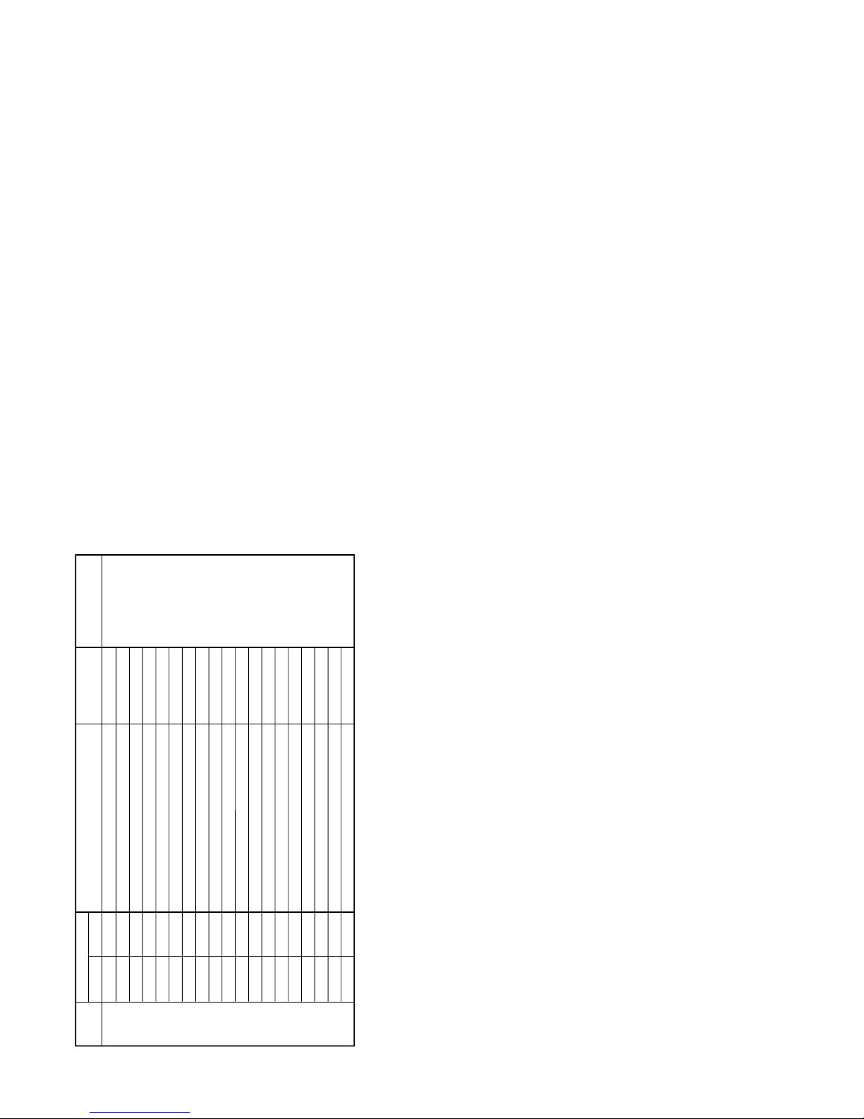
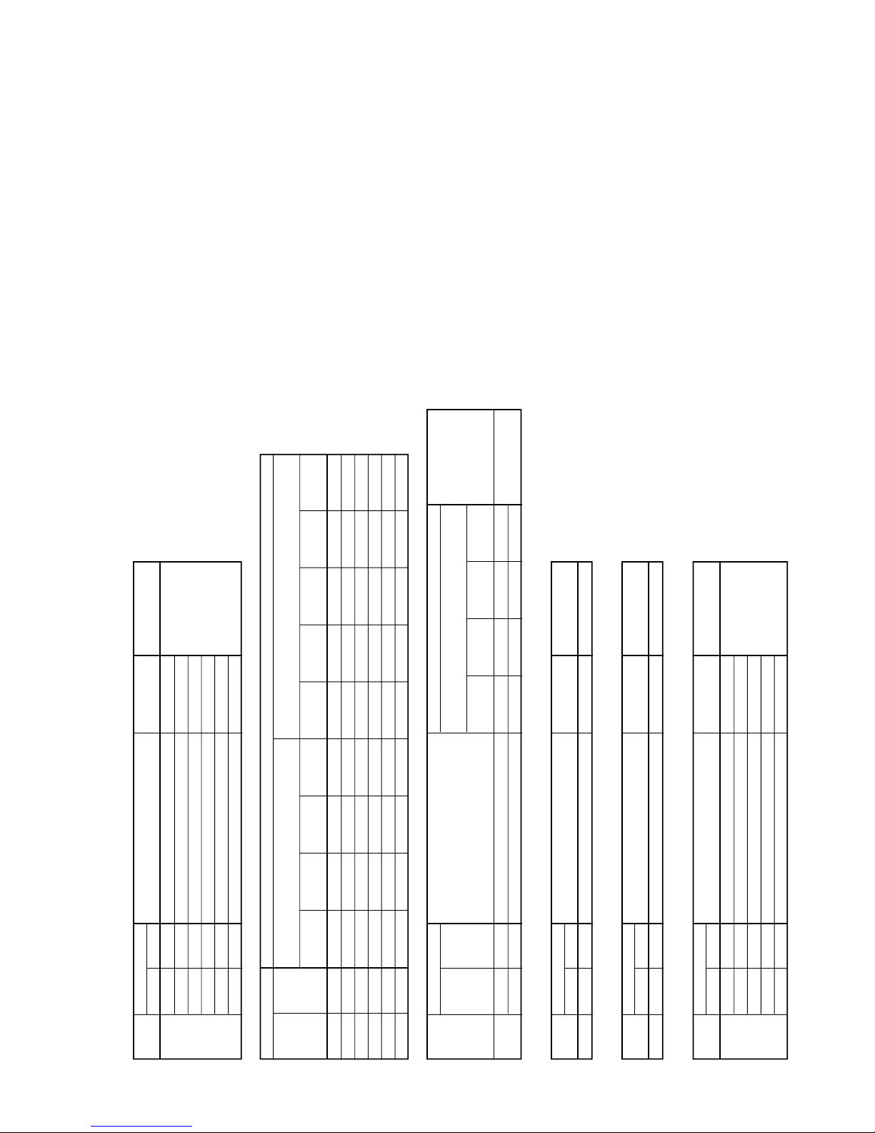
3-9. SERVICE LIST
Category
Item
Function Standard Data
Device Name
No. Name (Slave Address)
OSD 0 OSV OSD V Position 32 CXP961F064(60H)
1 OSH OSD H Position 13
2 FW1 OSD ODD/EVEN Field Window Setup #1 7
3 FW2 OSD ODD/EVEN Field Window Setup #2 20
4 VOF OSD V Position (Offset) *1
OSD: Standard Data *1
Item Standard Data
No. Name
OSD V OFFSET
INDEX60 FAVORITE50 FAVORITE60 TWIN50 TWIN60 HD50 HD60 MS VCOMP VCOMP60 VCOMP100 VCOMP120
4 VOF 32 32 32 32 32 32 32 32 32 32 32 32
OSD: Standard Data *1
Item
Standard Data
No. Name
OSD V OFFSET
FULL51 FULL61 FULL101 FULL120 WDZM50 WDZM60 WDZM100 WDZM120 ZOOM50 ZOOM60 ZOOM100 ZOOM120 INDEX50
4 VOF 32 32 16 16 32 32 16 16 32 32 16 16 32
Note
•
: The data value of each mode. Other are set up by each mode.
•
: Shaded items are fixed data.
•
: Though data value is indicated on the screen, it is not used.
• Standard data listed on the Adjustment Item Table are reference valies, therefore it may be different for each model and each
m
ode.
• Note for Different Data :
Those are the standard data values written on the microprocessor. Therefore , the data values of the modes and stored respectiv
ely in the memory.
In case of a device replacement, adjustment by rewriting the data value is necessary for some items.
– 20 –
KP-FWS57M90
RM-1007
Category
Item
Function Standard Data
Device Name
No. Name (Slave Address)
MSP 0 WST W/G Stereo Threshold 21 MSP3415D(84H)
1 WBT W/G Bilingual Threshold 236
2 WLL W/G Monaural Threshold 5
3 WAC W/G Agreement Count 1
4 WDL W/G Search Delay48
5 NDL NICAM Search Delay32
6 SDL Stereo status Read Delay16
7 AGC AGC Switch Auto/Constant 1
8 REL AGC Gain at Constant Mode
40
9 CRM Carrier muting on/off 0
10 ACO Audio Clock out on/off 1
11 FP FM Prescale for non-M system 27
12 FPM FM Prescale for M system 50
13 FH FM Prescale for HDEV 54
14 FHM FM Prescale for HDEV and M 101
15 WGP W/G Prescale 28
16 NIP NICAM Prescale 127
17 ERR Auto FM switch Threshold 80
18 VOL Loud Speaker gain 0700h to 07FFh
48
– 21 –
KP-FWS57M90
RM-1007
Category
Item
Function Standard Data
Device Name
No. Name (Slave Address)
PIC 0 PIC User Picture *1 PFED-PICTURE
1 COL User Color *1
2 BRI User Bright *1
3 HUE User Hue *1
4 SHP User Sharp *1
5 PIOF Picture Offset (Picture * (20-data)/20 * Eco(75%)
*1
PIC: Standard Data *1
Item Standard Data
No. Name
Picture/
Picture Offset
Sound Mode Table
Dynamic
Standard/
Hi-Fine/Soft Personal MS Normal(4:3) HD
Twin/Index/
Other
Drama
Pap
0 PIC 100 70 60 50
1 COL 60 55 50 50
2 BRI 45 50 50 50
3 HUE 50 50 50 50
4 SHP 45 50 50 50
5 PIOF 55050
Category
Item
Function
Standard Data
No. Name
Picture/
Device Name
Sound Mode Table
Dynamic
Standard/
Hi-Fine/Soft Personal
(Slave Address)
Drama
SOU 0 BAS User Bass 74 50 50 50 PFED-SOUND
1 TRE User Treble 50 50 42 50
Category
Item
Function Standard Data
Device Name
No. Name (Slave Address)
PFED 0 PFED PF-Engine Service * Pf-Engine
Category
Item
Function Standard Data
Device Name
No. Name (Slave Address)
GUID 0 GUID
Guide Select country ID (0:English,1:Tiwan,2:Korea,3:English)
0
Category
Item
Function Standard Data
Device Name
No. Name (Slave Address)
POWR 0 DLY1 Power On Delay1 4
1 DLY2 Power On Delay2 0
2 DLY3 Power On Delay3 4
3 ZDET Zero Detect Delay 31
4 ZTMO Zero Detect Timeout (*10ms min 300ms)
30
– 22 –
KP-FWS57M90
RM-1007
Category
Item
Function Standard Data
No. Name
OPM 0 APC APC Switch 1
1 TSY
TV System Selection under searching with Auto TV System
2
2 AFM Auto FM switch 1
3 DBL Disable Blueback function 1
4 SSO Speed CH Search Selection 1
5 SCH CH Selection for Shipping Condition
1
6 SCA Cable/Air Selection for Shipping Condition
1
7 DMG Disable Menu-operation Guide 0
8 VSN Enable Noise Reduction in
Video Mode 0
9 LBB Lower Blue Back Intensity 1
10 23P 2/3 Pull Down Mode 0: Force OFF, 1: Auto 1
11 DF DF_PHA 31
12 DQP DQP_PHA 31
13 VLIM Wide V-Center Limit *1
14 TUT1
Tune Wait Time Mode1 (Max) 30[ms] + 10[ms] * ser
vice_data
8
15 TUT2
Tune Wait Time Mode2 (Max) 30[ms] + 10[ms] * ser
vice_data
5
16 TUT3
Tune Wait Time Mode3 (Max) 30[ms] + 10[ms] * ser
vice_data
2
17 TUTW Tune Wait Time 6 point sense 5
18 3NR 3D-NR INIT (User Reset or Test Reset) 1
19 SIG No-Signal Detect number of lock detect count. *2
20 NSIG No-Signal Detect number of unlock detect counter
.*2
OPM: Standard Data *1
OPM: Standard Data *2
Item Standard Data
No. Name
V-Center Limit
WIDEZOOM WIDEZOOM
ZOOM 50Hz ZOOM 60Hz
50Hz 60Hz
13 VLIM 15 15 15 15
Item Standard Data
No. Name
Signa-Detect
RF Video
19 SIG 0 0
20 NSIG 0 0
Category
Item
Function Standard Data
Device Name
No. Name (Slave Address)
OPB 0 OP0 Optional Bits 0 60 Option-Bits
1 OP1 Optional Bits 1 107
2 OP2 Optional Bits 2 3
3 OP3 Optional Bits 3 47
4 OP4 Optional Bits 4
Category
Item
Function Standard Data
Device Name
No. Name (Slave Address)
SRV 0 COM Service Command *
– 23 –
KP-FWS57M90
RM-1007
Category
Item
Function Standard Data
No. Name
DEF1 0 VPOS 18
1 VSIZ 27
2 VLIN 5
3 VSCO *1
4 VCEN 31
5 VPIN *2
6 NSCO 31
7 HTPZ 15
8 ZOOM *3
9 APSW *4
10 ASPT *5
11 SCRL *5
12 UVLN *6
13 LVLN *6
14 VPSO *7
DEF1: Standard Data *1
Item Standard Data
No. Name WideZoom Other
3 VSCO 10 8
DEF1: Standard Data *2
Item Standard Data
No. Name Vcomp Othe
5 VPIN 15 15
DEF1: Standard Data *3
Item Standard Data
No. Name
Zoom
Other
WideZoom
8 ZOOM 1 0
DEF1: Standard Data *4
Item Standard Data
No. Name
HD
SD
50Hz 60Hz
9 APSW 1 0 1
DEF1: Standard Data *5
Item Standard Data
No. Name
Full VComp/Normal
50Hz 60Hz 100Hz 120Hz 50Hz 60Hz 100Hz 120Hz
SD HD SD HD SD SD SD SD SD SD
10 ASPT 6 17
51436543
11 SCRL 29 29 29 29 29 29 29 29 29 29
DEF1: Standard Data *5
Item Standard Data
No. Name
WideZoom Zoom
50Hz 60Hz 100Hz 120Hz 50Hz 60Hz 100Hz 120Hz
SD SD SD SD SD SD SD SD
10 ASPT 23 23 22 22 50 50 49 49
11 SCRL 29 29 29 29 29 29 29 29
DEF1: Standard Data *6
Item Standard Data
No. Name
Zoom
Other
WideZoom
12 UVLN 4 0
13 LVLN 4 0
DEF1: Standard Data *7
Item Standard Data
No. Name 50Hz 60Hz 100Hz 120Hz
14 VPSO 8 7 4 2
– 24 –
KP-FWS57M90
RM-1007
Category
Item
Function Standard Data
No. Name
DEF2 0 HCNT 31
1 HPOS *1
2 HSIZ *2
3 SLIN *2
4 MPIN *2
5 PIN *2
6 UCP *2
7 LCP *2
8 PPHA *3
9 VANG 31
10 LANG 31
11 VBOW 31
12 LBOW 31
13 UXCG 0
14 LXCG 0
15 UXCP 2
16 LXCP 2
17 XCPP 0
18 PPHO *4
19 PINO *5
20 UCPO *5
21 LCPO *5
22 VAOC 0
23 HIHS *6
24 HISL *6
25 HIMP *6
26 HIPN *6
DEF2: Standard Data *1
Item Standard Data
No. Name HD SD
1 HPOS 24 24
DEF2: Standard Data *2
Item Standard Data
No. Name WideZoom Other
2 HSIZ 16 16
3 SLIN 7 7
4 MPIN 0 0
5 PIN 6 6
6 UCP 31 31
7 LCP 31 31
DEF2: Standard Data *3
Item Standard Data
No. Name
Zoom
Other
WideZoom
8 PPHA 31 31
DEF2: Standard Data *5
Item Standard Data
No. Name
60Hz 100Hz 120Hz
WideZoom Other WideZoom Other WideZoom Other
19PINO000000
20 UCPO 0 0 0 0 0 0
21 LCPO 0 0 0 0 0 0
DEF2: Standard Data *4
Item Standard Data
No. Name 50Hz 60Hz 100Hz 120Hz
18 PPHO 7 7 7 7
DEF2: Standard Data *6
Item Standard Data
No. Name
WideZoom /
Other
VComp
23 HIHS 1 1
24 HISL 1 1
25 HIMP 2 2
26 HIPN 2 2
– 25 –
KP-FWS57M90
RM-1007
Category
Item
Function Standard Data
No. Name
DEF3 0 HBLK 1
1 LBLK *1
2 RBLK *1
3 VBLK *2
4 TBLK *3
5 BBLK *3
6 AFCM 3
7 JUMP *4
8 VDJP *5
9 AKBT *6
DEF3: Standard Data *1
Item Standard Data
No. Name HD SD
1 LBLK 63 63
2 RBLK 23 23
DEF3: Standard Data *2
DEF3: Standard Data *3
Item Standard Data
No. Name
Full VComp/Normal
50Hz 60Hz 100Hz 120Hz 50Hz 60Hz 100Hz 120Hz
SD HD SD HD SD SD SD SD SD SD
4 TBLK 0 15 0 4 12 8 0 0 12 8
5 BBLK 0 15 0 6 15 8 0 0 15 8
DEF3: Standard Data *3
Item Standard Data
No. Name
WideZoom
50Hz 60Hz 100Hz 120Hz
SD SD SD SD
4 TBLK 7 7 7 7
5 BBLK 7 7 7 7
DEF3: Standard Data *3
Item Standard Data
No. Name
Zoom
50Hz 60Hz 100Hz 120Hz
SD SD HD SD SD
4 TBLK 7 7777
5 BBLK 7 7777
DEF3: Standard Data *4
Item Standard Data
No. Name Vcomp Other
7 JUMP 0 0
DEF3: Standard Data *5
Item Standard Data
No. Name
Zoom
HD Other
WideZoom
8VDJP 1 1 1
Item Standard Data
No. Name
Zoom
Other
WideZoom
3 VBLK 0 1
– 26 –
KP-FWS57M90
RM-1007
DEF3: Standard Data *6
Item Standard Data
No. Name
Full VComp/Normal
50Hz 60Hz 100Hz 120Hz 50Hz 60Hz 100Hz 120Hz
SD HD SD HD SD SD SD SD SD SD
9 AKBT 22 9 16 16 9 9 22 16 9 14
DEF3: Standard Data *6
Category
Item
Function Standard Data
No. Name
DEF4 0 QPDC *1
1 QPDV *1
2 QPDP *1
3QPAM *1
4QPAV *1
5QPAP *1
6 COPY 0
Item Standard Data
No. Name
WideZoom Zoom
50Hz 60Hz 100Hz 120Hz 50Hz 60Hz 100Hz 120Hz
SD SD SD SD SD SD SD SD
9 AKBT 99999999
DEF4: Standard Data *1
Item Standard Data
No. Name Vcomp Other
0 QPDC 42 42
1 QPDV 63 63
2 QPDP 6 6
3QPAM 38 38
4QPAV 47 47
5QPAP 6 6
Category
Item
Function Standard Data
No. Name
DEF5 0 VON 1
1 EWDC 0
2 AGCS 0
3 ACMP 0

– 27 –
KP-FWS57M90
RM-1007
0BROF230323030202
1 GAMM 3 16131614161
6BLK420242023202
LUMA: Standard Data *1
Item Standard Data
No. Name
Comp
480_60P 576_50P 720_60P
Dynamic Standard Hi-fine Personal Dynamic Standard Hi-fine Personal Dynamic Standard Hi-fine Personal
0BROF230323032303
1 GAMM 3 16131613161
6BLK420242024202
LUMA: Standard Data *1
Item Standard Data
No. Name
CV/YC Comp
576_50I 480_60I 576_50I
Dynamic Standard Hi-fine Personal Dynamic Standard Hi-fine Personal Dynamic Standard Hi-fine Personal
0BROF23032313
1 GAMM 3 1 6
13161
6BLK42024202
LUMA: Standard Data *1
Item Standard Data
No. Name
CV/YC
480_60I
NTSC PAL
Dynamic Standard Hi-fine Personal Dynamic Standard Hi-fine Personal
0BROF573757375737
1 GAMM 5 16151615161
6BLK420242024202
LUMA: Standard Data *1
Item Standard Data
No. Name
RF
480_60I
576_50I
NTSC PAL
Dynamic Standard Hi-fine Personal Dynamic Standard Hi-fine Personal Dynamic Standard Hi-fine Personal
Category
Item
Function Standard Data
No. Name
LUMA 0 BROF *1
1 GAMM *1
2 GAMS *2
3 RGAM *2
4 GGAM *2
5 BGAM *2
6 BLK *1
7 APED *3
8 DCTR *3
9 ABLM *3
– 28 –
KP-FWS57M90
RM-1007
0BROF020202020202
1 GAMM 4 16141614161
6BLK320232023202
LUMA: Standard Data *1
Item Standard Data
No. Name
Comp
720_50P 1080_60I 1080_50I
Dynamic Standard Hi-fine Personal Dynamic Standard Hi-fine Personal Dynamic Standard Hi-fine Personal
0BROF230323032303
1 GAMM 3 16131613161
6BLK420242024202
LUMA: Standard Data *1
Item Standard Data
No. Name
RGB
480_60I 576_50I 480_60P
Dynamic Standard Hi-fine Personal Dynamic Standard Hi-fine Personal Dynamic Standard Hi-fine Personal
0BROF02020202
1 GAMM 4 1 6
14161
6BLK32023202
LUMA: Standard Data *1
Item Standard Data
No. Name
RGB
1080_60I 1080_50I
Dynamic Standard Hi-fine Personal Dynamic Standard Hi-fine Personal
0BROF00000000
1 GAMM 7 4 6 47464
6BLK00000000
LUMA: Standard Data *1
Item Standard Data
No. Name
MS
Index Full
Dynamic Standard Hi-fine Personal Dynamic Standard Hi-fine Personal
0BROF230302020202
1 GAMM 3 16141614161
6BLK420232023202
LUMA: Standard Data *1
Item Standard Data
No. Name
RGB
576_50P 720_60P 720_50P
Dynamic Standard Hi-fine Personal Dynamic Standard Hi-fine Personal Dynamic Standard Hi-fine Personal
– 29 –
KP-FWS57M90
RM-1007
0BROF000000000000
1 GAMM 7 46474647464
6BLK000000000000
LUMA: Standard Data *1
Item Standard Data
No. Name
MS
Popup Player Movie
Dynamic Standard Hi-fine Personal Dynamic Standard Hi-fine Personal Dynamic Standard Hi-fine Personal
0BROF2303
1 GAMM
3161
6BLK4202
LUMA: Standard Data *1
Item Standard Data
No. Name
Twin
All Format
Dynamic Standard Hi-fine Personal
LUMA: Standard Data *2
Item Standard Data
No. Name GAMMA0 GAMMA1 GAMMA2 GAMMA3 GAMMA4 GAMMA5 GAMMA6 GAMMA7
2 GAMS 0 15
0770157
3 RGAM 0 6 7688210
4 GGAM 0 6 7688210
5 BGAM 0 6
7688210
LUMA: Standard Data *3
Item Standard Data
No. Name BLK0 BLK1 BLK2 BLK3 BLK4 BLK5 BLK6 BLK7
7 APED 0 0 121130
8 DCTR 0 0 4 8 10 5 9 0
9 ABLM 0 0 011110
– 30 –
KP-FWS57M90
RM-1007
0 CLOF 0 30303030303
1 HUOF 2 22222223434
18AXIS322232221000
COLR: Standard Data *1
Item Standard Data
No. Name
RF
480_60I
576_50I
NTSC PAL
Dynamic Standard Hi-fine Personal Dynamic Standard Hi-fine Personal Dynamic Standard Hi-fine Personal
Category
Item
Function Standard Data
No. Name
COLR 0 CLOF *1
1 HUOF *1
2 RDRV 35
3 GDRV 35
4 BDRV 34
5 RCUT 20
6 GCUT 31
7 BCUT 32
8 SBRT 18
9 DCOL 3
10 WBSW *2
11 SBOF *2
12 RDOF *2
13 GDOF *2
14 BDOF *2
15 RCOF *2
16 GCOF *2
17 BCOF *2
18 AXIS *1
19 R-YR *3
20 R-YB *3
21 G-YR *3
22 G-YB *3
0 CLOF 1 4 0 41404
1 HUOF 3 3 3 33333
18AXIS32223222
COLR: Standard Data *1
Item Standard Data
No. Name
CV/YC
480_60I
NTSC PAL
Dynamic Standard Hi-fine Personal Dynamic Standard Hi-fine Personal
 Loading...