

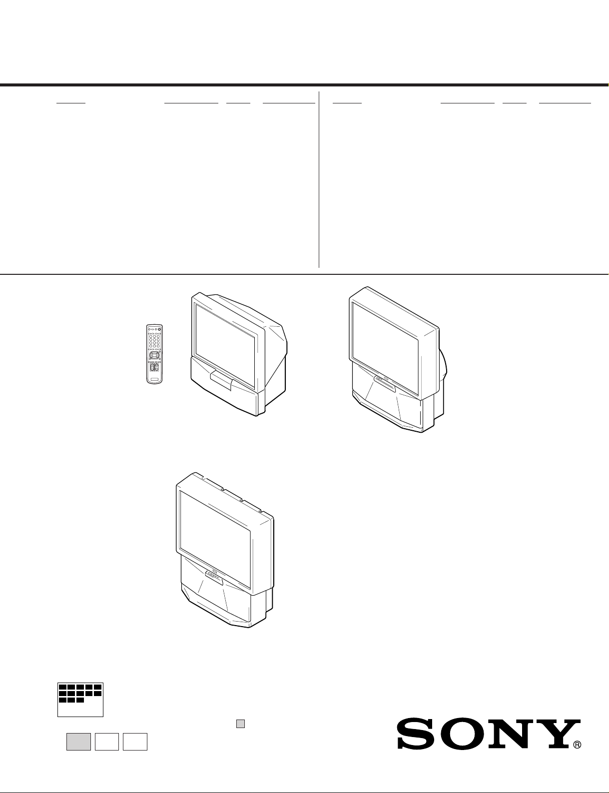
SONY KP-EF41NK2, KP-EF41ME2, KP-EF41MN2, KP-EF41SN2, KP-EF48NK2 SERVICE MANUAL
...
SERVICE MANUAL
RG-2
CHASSIS
MODEL COMMANDER DEST. CHASSIS NO.
KP-EF41HK2
KP-EF41ME2
KP-EF41MN2
KP-EF41SN2
KP-EF48HK2
KP-EF48ME2
KP-EF48MN2
KP-EF48SN2
RM-871 HK SCC-N71E-A
RM-871 ME SCC-N72E-A
RM-871 GE SCC-N69E-A
RM-871 AUS SCC-N73E-A
RM-871 HK SCC-N71C-A
RM-871 ME SCC-N72C-A
RM-871 GE SCC-N69C-A
RM-871 AUS SCC-N73C-A
MODEL COMMANDER DEST. CHASSIS NO.
KP-EF53HK2
KP-EF53ME2
KP-EF53MN2
KP-EF53SN2
RM-871 HK SCC-N71B-A
RM-871 ME SCC-N72B-A
RM-871 GE SCC-N69B-A
RM-871 AUS SCC-N73B-A
KP-EF41HK2/EF41ME2/
KP-EF41MN2/EF41SN2
KP-EF53HK2/EF53ME2/
KP-EF53MN2/EF53SN2
MICROFILM
∗ Please file according to model size. ...
KP-EF48HK2/EF48ME2/
KP-EF48MN2/EF48SN2
PROJECTION TV
41
48 53

KP-EF41HK2/ME2/MN2/SN2, EF48HK2/ME2/MN2/SN2,
KP-EF53HK2/ME2/MN2/SN2 RM-871
SPECIFICATIONS
Projection system
3 picture tubes, 3 lenses, horizontal in-
line system
Picture tube 7 inch high-brightness monochrome
tubes (6.3 raster size), with optical
coupling and liquidcooling system
Projection lenses High performance, large-diameter
hybrid lens F1.0
Screen size 41 inches (KP-EF41)
48 inches (KP-EF48)
53 inches (KP-EF53)
Television system
B/G, I, D/K, M
Color system PAL, PAL 60, SECAM, NTSC
3.58
NTSC
4.43,
Channel coverage
B/G
VHF: E2 to E12
UHF: E21 to E69
CATV: S01 to S03, S1 to S41
I
UHF: B21 to B68
CATV: S01 to S03, S1 to S41
D/K
VHF: C1 to C12, R1 to R12
UHF: C13 to C57, R21 to R60
CATV: Z1 to Z39, S01 to S03, S1 to S41
M
VHF: A2 to A13
UHF: A14 to A79
CATV: A-8 to A-2, A to W+4,
W+6 to W+84
Stereo system NICAM stereo B/G, I, D/K
A2 stereo (German) B/G
Antenna 75 ohm external antenna terminal
Audio output (Speaker)
15 W × 2
Number of terminals
Video Input: 4, Output: 1
phono jacks, 1 Vp-p, 75 ohms
Audio Input: 5, Output: 1, VARIABLE output:
1, phono jacks, 500 mVrms
S video Input: 2,
Y: 1 Vp-p, 75 ohms, unbalanced, sync
negative,
C: 0.286 Vp-p, 75 ohms
Component video
Input: 1, phono jacks
Y: 1.0 Vp-p, 75 ohms, sync negative
/B-Y: 0.7 Vp-p, 75 ohms
C
B
C
/R-Y: 0.7 Vp-p, 75 ohms
R
Audio: 500 mVrms
Headphone Output: 1, minijack
Power requirement
110 – 240 V AC, 50/60 Hz
Power consumption
160 W
Dimensions (w/h/d)
948 × 992 × 511 mm (KP-EF41)
1106 × 1336 × 558 mm (KP-EF48)
1218 × 1413 × 602 mm (KP-EF53)
Mass Approx. 43 kg (KP-EF41)
Approx. 66 kg (KP-EF48)
Approx. 70 kg (KP-EF53)
Supplied accessories
Remote commander RM-871 (1)
Size R6 (AA) battery (2)
Optional accessory
AV rack SU-EF41 (KP-EF41),
SU-EF4853 (KP-EF48/EF53)
Design and specifications are subject to change without
CAUTION
SHORT CIRCUIT THE ANODE OF HTE PICTURE TUBE
AND THE ANODE CAP TO THE METAL CHASSIS, CRT
SHIELD, OR CARBON PAINTED ON THE CRT, AFTER
REMOVING THE ANODE.
SAFETY-RELATED COMPONENT WARNING!!
COMPONENTS IDENTIFIED BY SHADING AND MARK
! ON THE SCHEMATIC DIAGRAMS, EXPLODED
VIEWS AND IN THE PARTS LIST ARE CRITICAL TO
SAFE OPERATION. REPLACE THESE COMPONENTS
WITH SONY PARTS WHOSE PART NUMBERS APPEAR AS SHOWN IN THIS MANUAL OR IN SUPPLEMENTS PUBLISHED BY SONY.
– 2 –

KP-EF41HK2/ME2/MN2/SN2, EF48HK2/ME2/MN2/SN2,
KP-EF53HK2/ME2/MN2/SN2 RM-871
TABLE OF CONTENTS
Section Title PageSection Title Page
1. GENERAL ................................................................. 4
2. DISASSEMBLY
2-1. Rear Board Removal ......................................... 19
2-2. Main Bracket Section Removal ........................ 20
2-3. Service Position ................................................. 21
2-4. H1 Board, H2 Board and Resistor
(High Voltage) Removal ................................... 22
2-5. Beznet Section Removal ................................... 24
2-6. G Board Removal ............................................... 26
2-7. P1 Board and V2 Board Removal...................... 26
2-8. UG Board, AG Board and S Board Removal .... 26
2-9. High-Voltage Cable Installation and Removal.. 27
2-10. Mechasel Assy Removal .................................... 27
2-11. Chassis Block Removal...................................... 28
(1) H1, H2 Boards and Resistor Removal .............. 28
(2) Main Bracket Removal ...................................... 29
(3) Chassis Block Removal ..................................... 30
3. SET-UP ADJUSTMENTS
3-1. Screen Voltage Adjustment
(Rough Alignment) ........................................... 31
3-2. Focus Adjustment .............................................. 31
3-3. Screen (G2) Adjustment .................................... 31
3-4. Deflection Yoke Tilt Adjustment ...................... 31
3-5. 2-Pole Magnet Adjustment ................................ 32
3-6. 4-Pole Magnet Adjustment ................................ 32
3-7. Defocus Adjustment (Blue) ............................... 32
3-8. Green and Red Focus Adjustment ..................... 32
3-8-1. Green and Red Lens Focus Adjustment ....... 32
3-8-2. Green and Red Electrical Focus
Adjustment .................................................... 32
6. DIAGRAMS
6-1. Block Diagrams .................................................. 49
6-2. Frame Schematic Diagram................................. 59
6-3. Circuit Boards Location ..................................... 62
6-4. Schematic Diagrams and Printed Wiring
Boards ................................................................. 63
(1) Schematic Diagram of AG (1/3) Board............. 67
(2) Schematic Diagram of AG (2/3) Board ............ 71
(3) Schematic Diagrams of AG (3/3), CB, CG and
CR Boards ......................................................... 75
(4) Schematic Diagram of E Board ......................... 79
(5) Schematic Diagram of D Board ........................ 89
(6) Schematic Diagrams of P1 and V2 Boards ....... 93
(7) Schematic Diagrams of H1, H2, S,
ZG and ZR Boards ............................................. 101
(8) Schematic Diagrams of G and UG Boards........ 104
6-5. Semiconductors ................................................. 109
7. EXPLODED VIEWS
7-1. Screen and Cover Block (KP-EF41) ................. 111
7-2. Cabinet and Panel Block (KP-EF41) ................ 112
7-3. Chassis and Picture Tube Block (KP-EF41) ..... 113
7-4. Screen and Cover Block (KP-EF48).................. 114
7-5. Cabinet and Panel Block (KP-EF48) ................. 115
7-6. Chassis and Picture Tube Block (KP-EF48) ..... 116
7-7. Screen and Cover Block (KP-EF53).................. 117
7-8. Cabinet and Panel Block (KP-EF53) ................. 118
7-9. Chassis and Picture Tube Block (KP-EF53) ..... 119
8. ELECTRICAL PARTS LIST ............................ 120
4. SAFETY RELATED ADJUSTMENT
4-1. HV Hold Down Adjustment ............................. 33
5. CIRCUIT ADJUSTMENTS ................................ 34
5-1. Adjustments with Commander ......................... 34
5-2. Adjustment Method ........................................... 35
5-3. Adjustment After IC1001 and IC1702
Replacement ....................................................... 35
5-4. Registration (Convergence)Adjustment
Method ................................................................ 42
5-5. Auto Convergence Adjustment .......................... 47
5-6. White Balance Adjustment ................................ 48
5-7. Text Position Adjustment................................... 48
5-8. Picture Quality Adjustments ............................. 48
– 3 –
The operating instructions mentioned here are partial abstracts
6
-EN
Getting Started
1
L
(MONO)
R
2
3
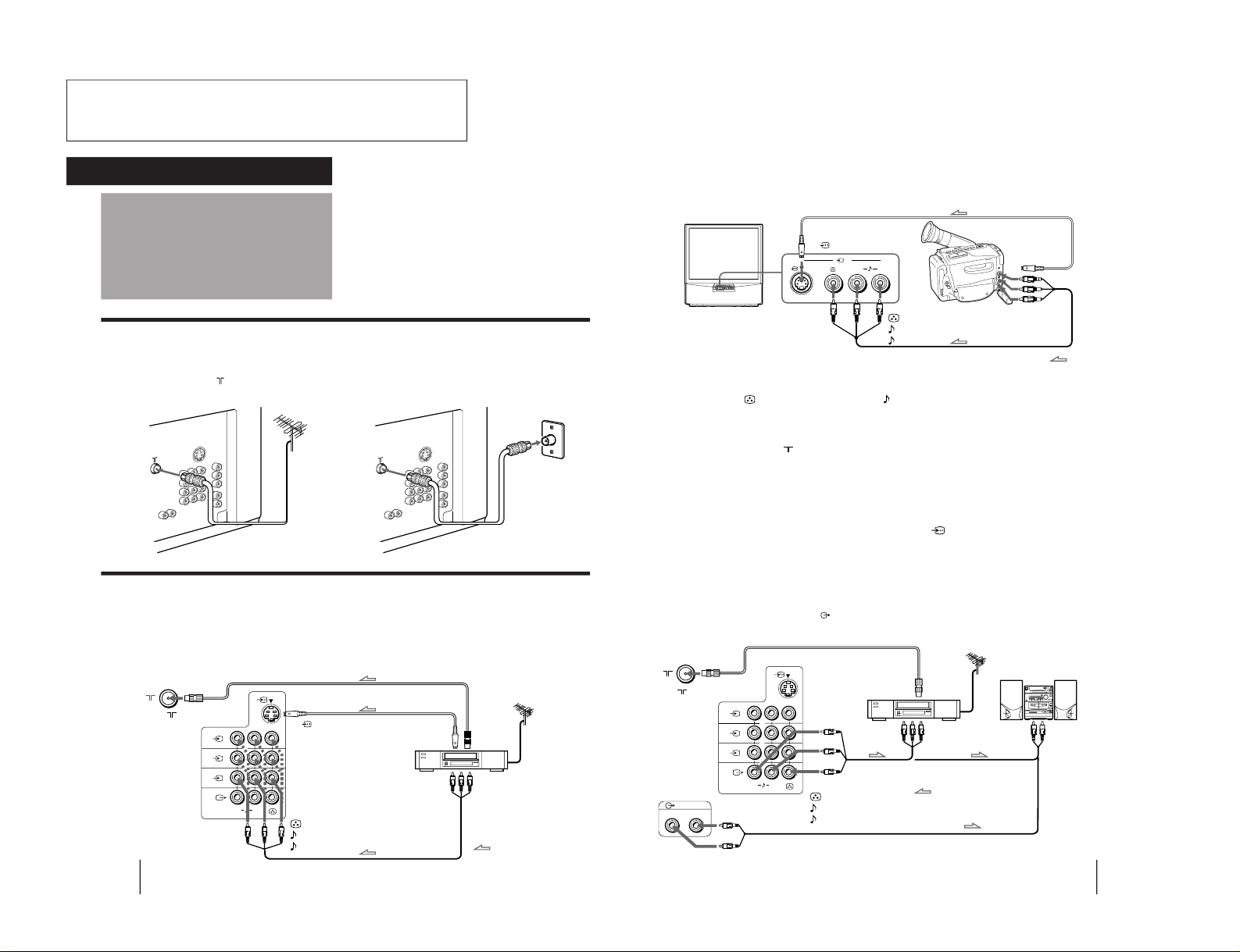
Connecting a VHF antenna or a combination VHF/UHF antenna
— 75-ohm coaxial cable (round)
Attach an optional IEC antenna connector to the 75-ohm coaxial cable.
Plug the connector into the
(antenna) socket at the rear of the TV.
Connecting optional equipment
You can connect optional audio/video equipment to your TV such as a VCR, multi disc player, camcorder, video
game or stereo system.
Connecting video equipment using video input jacks
Connections
On a wall
Rear of TV
Rear of TV
or
Rear of TV
VCR
to
S video
output
to
antenna
output
to video and
audio outputs
: Signal flow
Getting Started
to (antenna) socket
to
…
1, 2, or 3 (video input)
(yellow)
-L (MONO)(white)
-R (red)
to
(S video input)
7
-EN
Getting Started
1
L
(MONO)
R
2
3
(VARIABLE)
RL
Camcorder
to S video output
to video and
audio outputs
: Signal flow
Rear of TV
VCR
to
antenna
output
to video and
audio inputs
Audio system
to audio
inputs
: Signal flow
or
L( MONO)
R
3
to (S video input)
to
…
3 (video input)
(yellow)
-L (MONO)(white)
-R (red)
to
(antenna) socket
to
Ú
(monitor/TV output)
(yellow)
-L (MONO)(white)
-R (red)
When connecting a monaural VCR
Connect the yellow plug to
(video input) and the black plug to
-L (MONO) (audio input).
When connecting video game equipment
Connect video game equipment to the … 3 (video input) jacks at the front or the rear of your TV.
When connecting a VCR to the
(antenna) terminal
Preset the signal output from the VCR to the program position 0.
When connecting video equipment to the … 3 (video input) jacks at the front and the rear
Do not connect video equipment to the … 3 (video input) jacks at the front and the rear of your TV simultaneously; otherwise the picture
will not be displayed properly on the screen.
If both S Video and video signals are input simultaneously
The S video input signal is selected. To view a video input signal, disconnect the
(S video) connection.
Note on the video input
When no signal is input, the screen becomes blue.
Connecting audio/video equipment using Ú (monitor/TV output) jacks
When the audio cable is connected to the
(VARIABLE) jacks, you can adjust the volume with Á +/–.
Front of TV
from the Operating Instruction Manual. The page numbers of
the Operating Instruction Manual remein as in the manual.
– 4 –
SECTION1
GENERAL
8
-EN
Getting Started
COMPOMENT VIDEO OUT
S VIDEO OUT
LINE OUT
C
B
/B-YYCR/R-Y
R-AUDIO-L VIDEO
CR/
R-Y
C
B
/
B-Y
Y
L
R
1
L
(MONO)
R
2
3
LINE OUT
R-AUDIO-L VIDEO
Connecting a DVD player
C
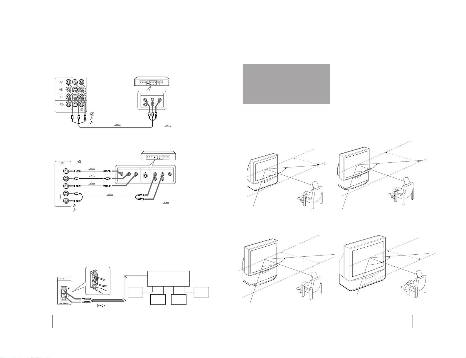
Connecting an amplifier with Dolby* Pro Logic decoder
Even though you use an amplifier with Dolby Pro Logic
decoder instead of the projection TV’s audio system, you
can still use the projection TV’s center speaker.
* Manufactured under license from Dolby Laboratories
Licensing Corporation.
DOLBY, the double-D symbol a and “PRO LOGIC” are
trademarks of Dolby Laboratories Licensing Corporation.
Amplifier with Dolby Pro
Logic decoder
Rear
speaker
(L)
Rear
speaker
(R)
Front
speaker
(L)
Front
speaker
(R)
to
(center speaker
inputs)
Rear of TV
Connecting a DVD player with component video output connecors
Notes
• Since the high quality pictures on a DVD disc contain a lot of
information, picture noise may appear. In this case, adjust the
sharpness (SHARP) in the VIDEO ADJUST menu. (See page 20.)
• Connect your DVD player directly to your TV. Connecting the
DVD player through other video equipment will cause unwanted
picture noise.
Rear of TV
: Signal flow
to audio/
video
outputs
DVD player
to
…
1, 2, or 3 (video input)
(yellow)
-L (MONO)(white)
-R (red)
Rear of TV
: Signal flow
-L (white)
-R (red)
to
(component video
input) Y/C
B
/B-Y/C
R
/R-Y
to component video
output
to audio output
DVD player
9
-EN
Getting Started
For the best picture quality, install the projection TV
within the areas shown below.
Optimum viewing area (Horizontal)
KP-EF41
Installing the
projection TV
KP-EF53
min 1.5m (5 ft.)
min 2.1m (7 ft.)
75°
75°
75°
75°
KP-EF48
KP-EF61
min 1.8m (6 ft.)
75°
75°
min 2.7m (9 ft.)
75°
75°
– 5 –
10
-EN
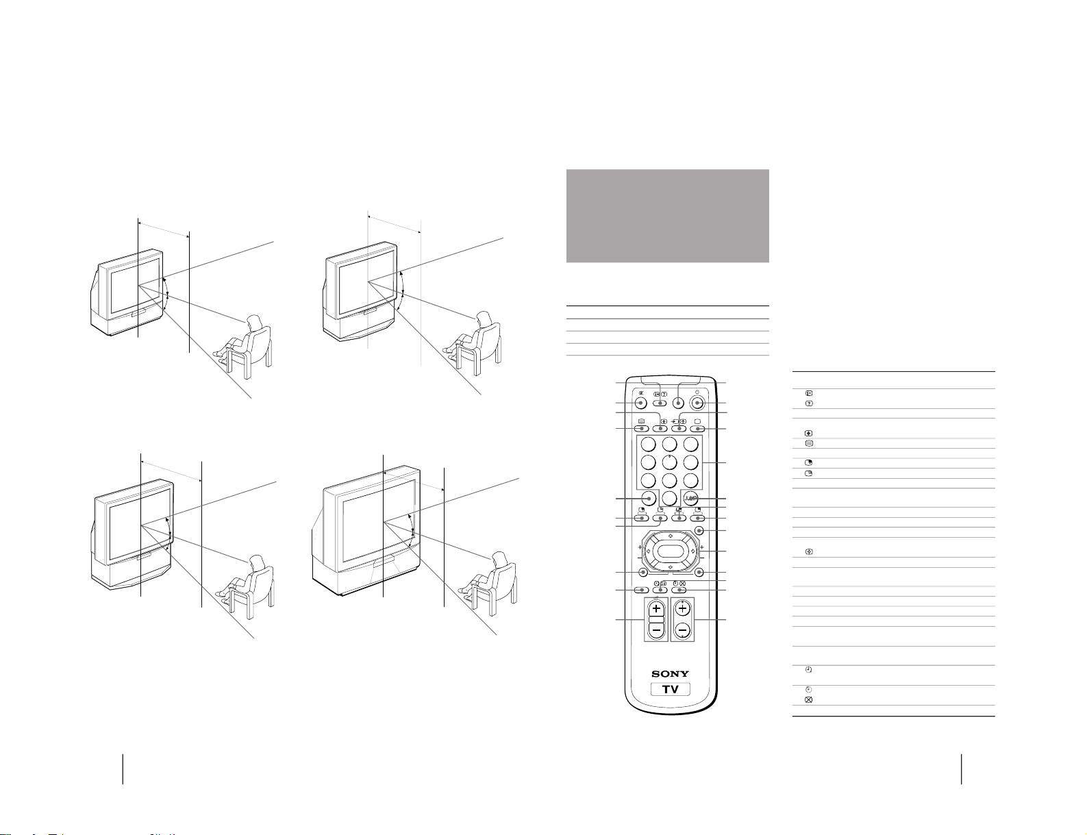
Getting Started
Optimum viewing area (Vertical)
KP-EF41
KP-EF53
min 2.1m (7 ft.)
min 2.7m (9 ft.)
min 1.5m (5 ft.)
27°
27°
27°
27°
KP-EF48
KP-EF61
min 1.8m (6 ft.)
27°
27°
27°
27°
11
-EN
Getting Started
Name Refer to page
On-screen display button 19
Teletext: Reveal button 29
Mute on/off button 19
Sound select button 24
Teletext: Enlarge button 29
Teletext button 28
Double-digit entering button 18
Input select for PIP button 26
PIP freezing button 27
PIP TEXT button 30
POWER BASSO button 22
Volume control button 18
GAME button 31
TV standby button 18
Input mode selector 19
Hold button 28
TV power on/TV mode selector 19
Number buttons 18
JUMP button 19
Swapping picture button 27
PIP display button 26
MENU button 12
Cursor control key 12
Enter button 12
PROGR INDEX button 25
Wake up button (not in use for your model)
Teletext: INDEX button 28
Sleep timer button 19
Teletext: Text clear button 29
Program selectors 18
Symbol
1
2 ¤
3 A/B
4
5 ÷
6
7
8 PIP TEXT
9 POWER
BASSO
!º .+/–
!¡ GAME
!™ u
!£ …
!¢ ;
!∞ 1,2,3,4,5,
6,7,8,9,0
!§ JUMP
!¶ a
!• ´
!ª MENU
@º V/b/v/B
ENTER
@¡ PROGR
INDEX
@™
©
@£
@¢ PROGR +/–
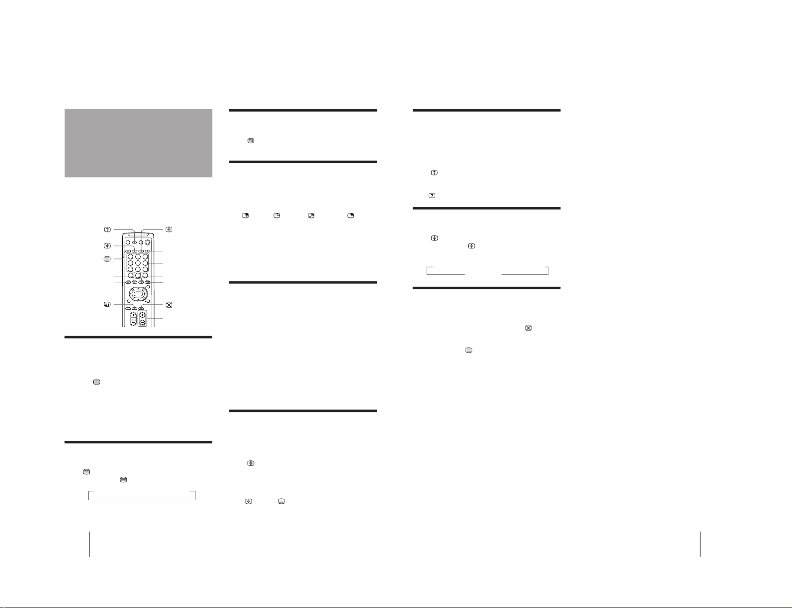
Names/symbols of buttons on the remote commander are indicated in different colors to represent the available
functions.
Label color Button function
White For general TV operations.
Green For Teletext operations.
Yellow For PIP and PROGRAM INDEX operations.
Getting to know the
remote commander
PROGR
MENU
PIP PROGR
A/B
GAME
PROGR
INDEX
PIP
TEXT
1
2
3
4
5
6
7
8
0
-/--
9
ENTER
POWER
BASSO
1
2
3
4
6
7
@¡
@™
5
8
9
!º
@£
@¢
@º
!ª
!•
!¶
!§
!∞
!¢
!£
!™
!¡
– 6 –

12
-EN
Getting Started
A/V CONTROL
PIP
FEATURES
Getting back to the previous menu
(except for AUTO PROGRAM)
Press V or v to move the cursor (z) to the first
line (N) of each menu, and press ENTER.
Cancelling the menu screen
Press MENU.
Notes (except for AUTO PROGRAM)
• When a menu is selected after pressing ENTER, the color of
both the menu and the menu symbol change and the cursor
(z) appears beside the first item of the menu.
• When an item on the menu is selected after pressing ENTER,
the color of the item changes.
• You can refer to the guide (
) at the bottom of the
menus (except for the A/V CONTROL and PRESET menus)
for the basic operations of the menu.
• If more than approximately 60 seconds elapse after you press a
button, the menu screen disappears automatically.
PIP
PIP: OFF
PIP TEXT
STRO BE
POS I T ION:
PROGR I ND EX
PRESET
Introducing the
menu system
You can preset TV channels, adjust the picture and sound qualities, and select some settings using the on-screen
menus. You can use the buttons on both the remote commander and the TV to operate the menus.
TV SYS: B/ G
AUTO P ROGRAM
VHF LO
W
PR: 01
A / V CONTROL
DYNAMIC
SOFT
STA NDARD
PERSONAL
V I DEO ADJUST
AUDIO ADJUST
GAME MODE
HYPER SURROUND :
OF F
MONITOR
AV OUT:
FE ATURES
CONVERGENCE
PRESET
SKIP:
PR02 OFF
TV SYS: B/ G
COL
SYS : AUTO
ENGL I SH
AUTO P ROGRAM
MANUAL PROGRAM
LA NGUAGE /
:
BASS
80
00
80
TREBLE
BALANCE
AUDIO ADJUST
SPEAKER:
MAIN
P I CTURE
50
90
0
50
V I DEO ADJUST
COLOR
BR I GHT
HUE
SHARP
VM: HIGH
50
0
TV SYS: B/G
VHF
LOW
PR: 01
AT T : OFF
MANUAL PROGRAM
VOLUME: 0
13
-EN
Getting Started
Changing the menu
language
3
Press V or v to move the cursor (z) to the
PRESET menu (
), and press ENTER.
4
Make sure the cursor (z) appears beside
LANGUAGE/
( ), and press ENTER.
5
Press V/b/v/B to select
( ), and press
ENTER.
All of the menus change to Chinese (Arabic).
6
Press MENU to return to the normal screen.
If you prefer Chinese (for MN, MG, HK and SN
models)/Arabic (for ME model) to English, you can
change the menu language. You can use buttons on
both the remote commander and the TV.
1
Press U to turn on the TV.
2
Press MENU.
MENU
ENTER
MENU
A / V CONTROL
DYNAMIC
SOFT
STA NDARD
PERSONAL
V IDEO AD JUST
AUDI O AD JUST
MENU
PRESET
SKIP: PR02 OFF
TV SYS: B /G
COL SYS: AUTO
ENGL I SH
AUTO PROGRAM
MANUAL P ROGRAM
LANGUAGE/
:
ENTER
ENTER
U
U
ENTER
MENU
– 7 –
14
-EN
Getting Started
You can preset TV channels easily by storing all the
receivable channels automatically. You can also preset
channels manually or disable program positions (see
page 16 ).
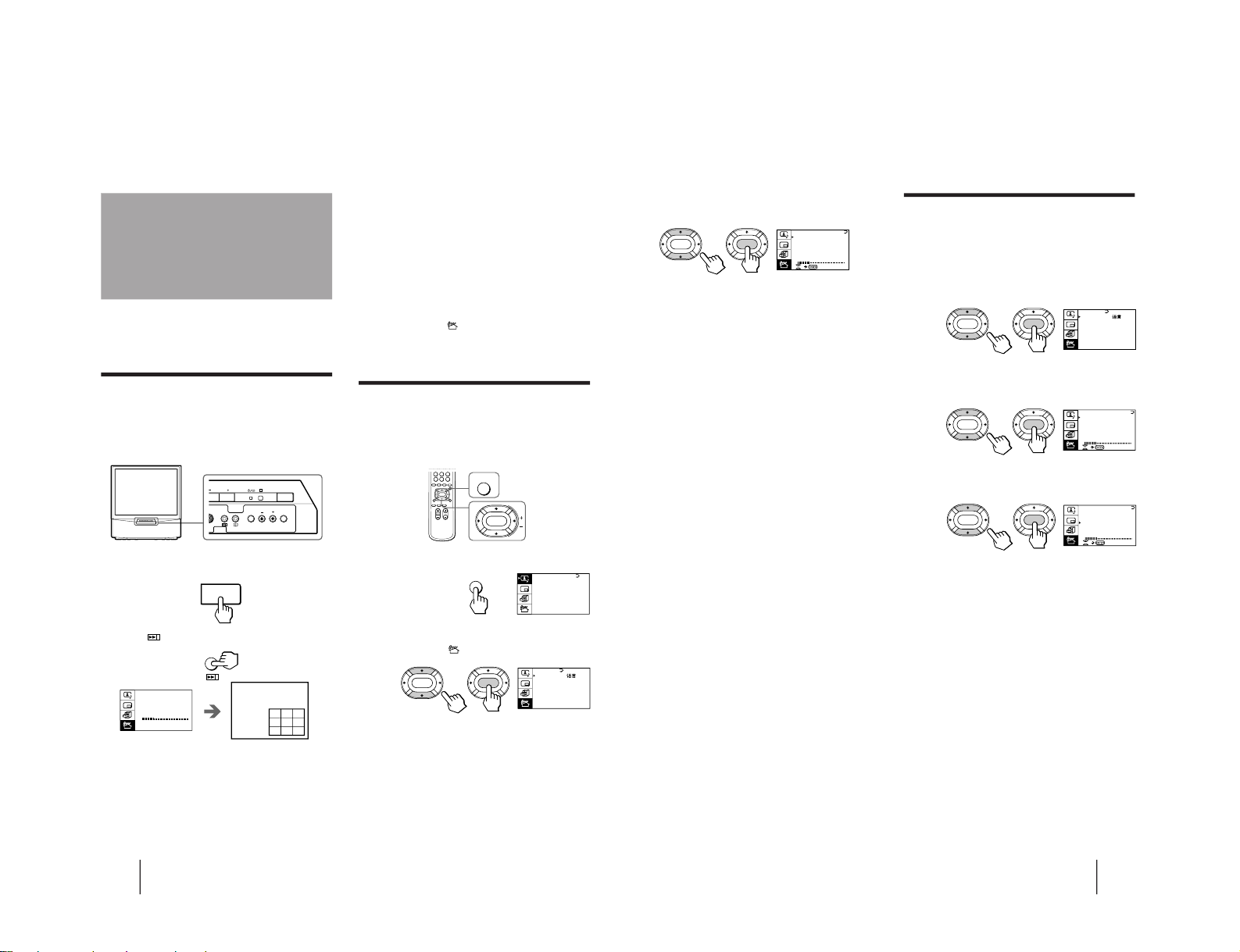
Presetting channels automatically
You can preset up to 100 TV channels in numerical
sequence from the program position 1. You can preset
channels automatically using the button on the TV or
the menu.
1
Press U to turn on the TV.
2
Press
.
The TV starts scanning and presetting channels
automatically. When all of the receivable channels
are stored, the AUTO PROGRAM menu disappears
and the first nine preset TV programs appear on the
nine sub screens. The nine sub screens disappear
after being displayed for several seconds.
Presetting channels
Note
• If you want to return to the normal screen while the nine sub
screens are being displayed, you can press PROGR INDEX on
the remote commander.
To preset channels automatically using
the menu
1 Press MENU.
2 Press V or v to move the cursor (z) to the
PRESET menu (
), and press ENTER.
3 Press V or v to move the cursor (z) to AUTO
PROGRAM, and press ENTER.
Presetting channels manually
To change the program position for a channel or to
receive a channel with a weak signal which you cannot
receive by automatic presetting, preset the channel
manually.
1
Press MENU.
2
Press V or v to move the cursor (z) to the
PRESET menu (
), and press ENTER.
3
Select your local TV system.
(1) Press V or v to move the cursor (z) to TV SYS, and
press ENTER.
(2) Press V/b/v/B until your local TV system appears
on the menu, and press ENTER.
MENU
ENTER
A / V CONTROL
DYNAMIC
SOFT
STA NDARD
PERSONAL
V IDEO AD JUST
AUDI O AD JUST
MENU
U
TV SYS:B/G
AUTO PROGRAM
VHF LO
W
PR: 01
123
456
789
PRESET
SKIP: PR02 OFF
TV SYS: B /G
COL SYS: AUTO
ENGL I SH
AUTO PROGRAM
MANUAL PROGRAM
LANGUAGE/
:
ENTER
ENTER
L(MONO)
R
3
PROGR
R
U
ENTER MENU
15
-EN
Getting Started
Attenuating the signal for individual
programs
If the TV signal is too strong, the picture may be
distorted. You can reduce the picture distortion by
attenuating the signal individually.
1
Display the PRESET menu.
2
Press V or v to move the cursor (z) to
MANUAL PROGRAM, and press ENTER.
3
Press V or v to move the cursor (z) to ATT,
and press ENTER.
4
Press V/b/v/B to select ON, and press ENTER.
4
Press V or v to move the cursor (z) to
MANUAL PROGRAM, and press ENTER.
5
Select the program position to which you
want to preset a channel.
(1) Make sure the cursor (z) appears beside PR, and
press ENTER.
(2) Press V/b/v/B until the program position you
want appears on the menu, and press ENTER.
6
Select the desired channel.
(1) Press V or v to move the cursor (z) to VHF LOW
(VHF Hi or UHF), and press ENTER.
(2) Press V/b/v/B until the desired channel picture
appears on the TV screen, and press ENTER.
7
Press MENU to return to the normal screen.
If the TV system is not properly selected
The picture color may be poor and/or the sound may
be noisy. In this case, select the appropriate TV system.
1 Press PROGR +/– or the number buttons to select
the program position.
2 Display the PRESET menu.
3 Press V or v to move the cursor (z) to TV SYS, and
press ENTER.
4 Press V/b/v/B until the appropriate TV system
appears, and press ENTER.
Notes
• The TV SYS (TV system), the ATT (attenuator), and the
VOLUME (volume offset) settings are memorized for each
program position.
• If you do not know your local TV system, consult your nearest
Sony dealer or authorized service center.
PRESET
SKIP: PR02 OFF
TV SYS: B /G
COL SYS: AUTO
ENGL I SH
AUTO PROGRAM
MANUAL P ROGRAM
LANGUAGE/
:
ENTER ENTER
TV SYS:B/G
VHF
LOW
PR: 01
AT T : OFF
MANUAL PROGRAM
ENTER
ENTER
VOLUME: 0
TV SYS:B/G
VHF
LOW
PR: 01
AT T : OFF
MANUAL PROGRAM
ENTER
ENTER
VOLUME: 0
TV SYS:B/G
VHF
LOW
PR: 01
AT T : OFF
MANUAL PROGRAM
ENTER ENTER
VOLUME: 0
– 8 –
16
-EN
Getting Started
Disabling program positions
By disabling unused or unwanted program positions,
you can skip those positions when you press PROGR
+/–.
1
Press MENU.
2
Press V or v to move the cursor (z) to the
PRESET menu (
), and press ENTER.
3
Press V or v to move the cursor (z) to SKIP,
and press ENTER.
4
Press V or v until the unused or unwanted
program position appears on the menu,
and press ENTER.
5
Press V/b/v/B to select ON, and press ENTER.
6
To disable other program positions, repeat
steps 4 and 5.
7
Press MENU to return to the normal screen.
To cancel the skip setting
1 Display the PRESET menu.
2 Press V or v to move the cursor (z) to SKIP, and
press ENTER.
3 Press V or v until the program position you want to
cancel the skip setting appears, and press ENTER.
4 Press V/b/v/B to select OFF, and press ENTER.
Presetting the volume level for
individual programs
If the volume of the selected program is louder than
that of other programs, set the volume level.
1
Press MENU.
2
Press V or v to move the cursor (z) to the
PRESET menu (
), and press ENTER.
3
Press V or v to move the cursor (z) to
MANUAL PROGRAM, and press ENTER.
4
Press V or v to move the cursor (z) to
VOLUME, and press ENTER.
5
Press V/b/v/B to set the level, and press
ENTER.
The level can be set as 0, –1, –2, ....–6 (minimum).
A / V CONTROL
DYNAMIC
SOFT
STA NDARD
PERSONAL
V IDEO AD JUST
AUDI O AD JUST
MENU
PRESET
SKIP: PR02 OFF
TV SYS: B /G
COL SYS: AUTO
ENGL I SH
AUTO PROGRAM
MANUAL PROGRAM
LANGUAGE/
:
ENTER ENTER
A / V CONTROL
DYNAMIC
SOFT
STA NDARD
PERSONAL
V IDEO AD JUST
AUDI O AD JUST
MENU
PRESET
SKIP: PR02 OFF
TV SYS: B /G
COL SYS: AUTO
ENGL I SH
AUTO PROGRAM
MANUAL PROGRAM
LANGUAGE/
:
ENTER
ENTER
TV SYS:B/G
VHF
LOW
PR: 01
AT T : OFF
MANUAL PROGRAM
ENTER ENTER
VOLUME: 0
17
-EN
Getting Started
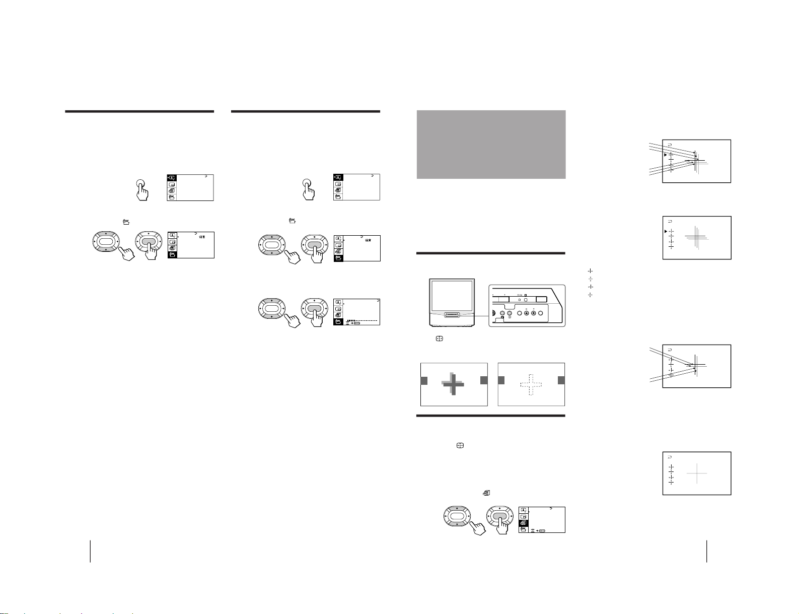
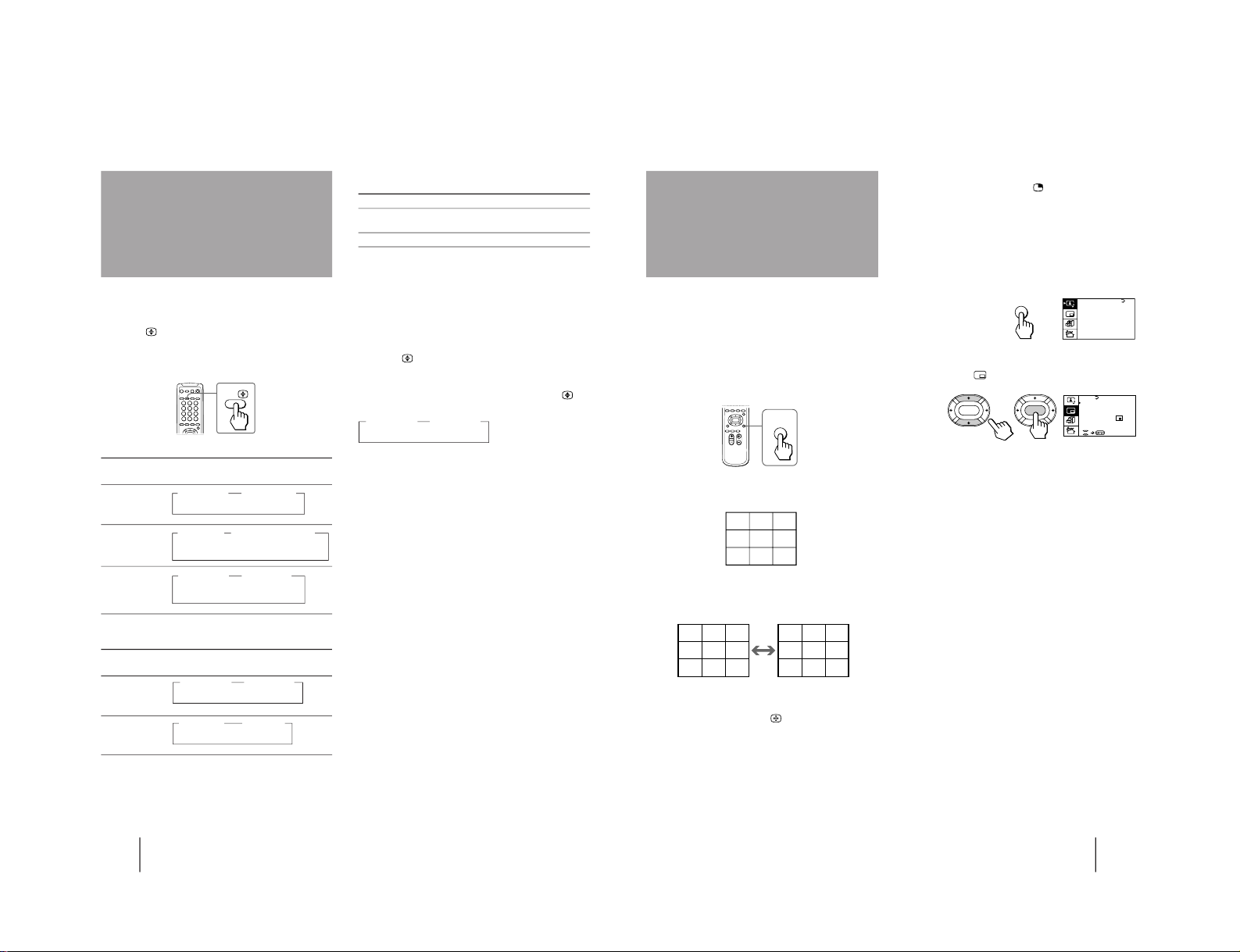
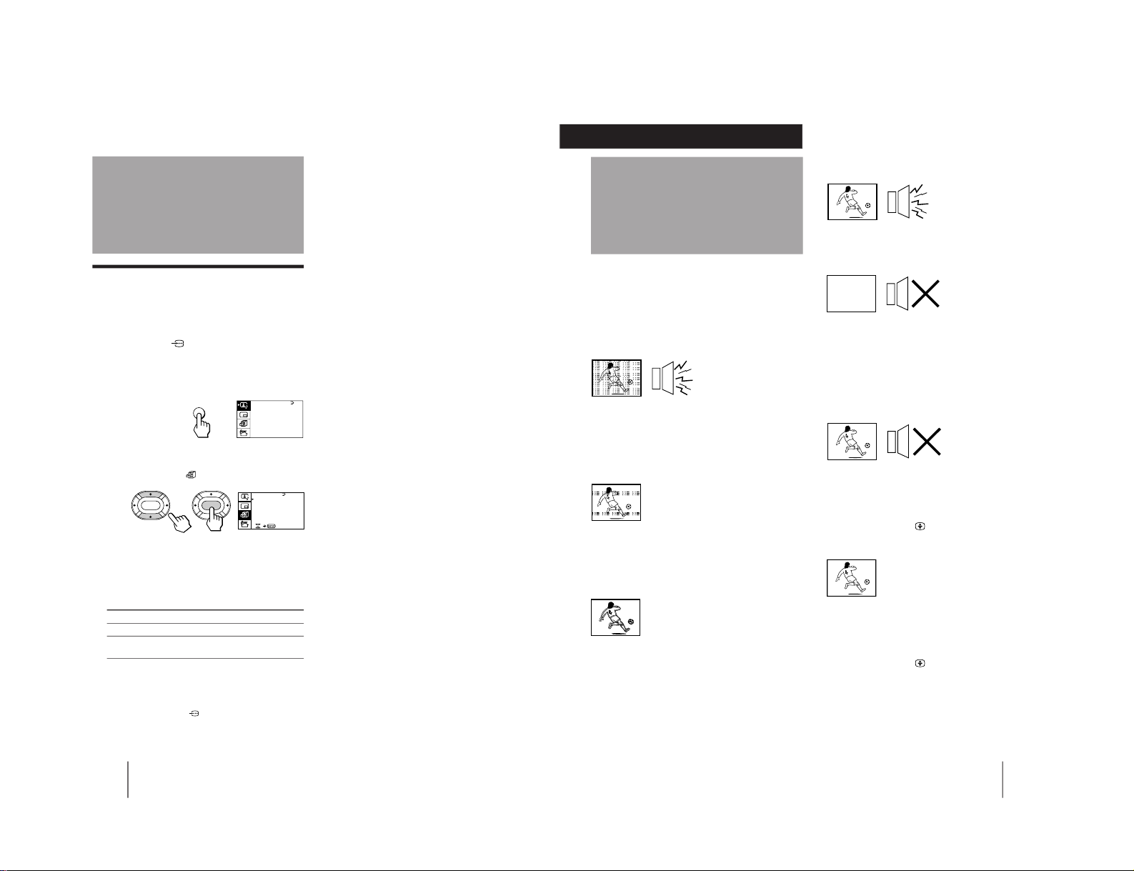
3
Press V or v to move the cursor (z) to
CONVERGENCE and press ENTER.
The CONVERGENCE adjustment screen appears.
4
Press V or v to move the cursor (z) to the
symbol showing the line you want to
adjust, and press ENTER.
: Red vertical line (left/right adjustment)
: Red horizontal line (up/down adjustment)
: Blue vertical line (left/right adjustment)
: Blue horizontal line (up/down adjustment)
5
Press V or v to move the line until it
converges with the center green line, and
press ENTER.
To move up/right, press V.
To move down/left, press v.
6
Repeat steps 4 and 5 to adjust the other
lines until all three lines converge and are
seen as a white cross.
7
Press MENU to return to the normal screen.
Adjusting the
convergence
(CONVERGENCE)
Before you use the projection TV, adjust convergence.
The projection tube image appears on the screen in
three layers (red, green and blue). If they do not
converge, the color is poor and the picture blurs. To
correct this, adjust convergence.
After 20-30 minutes of turning on the power, adjust
convergence.
Adjusting the convergence
automatically
Press on the TV.
The auto convergence function works for about 30
seconds.
Adjusting the convergence manually
When the auto convergence function does not work
correctly with
, adjust convergence by selecting
CONVERGENCE of the FEATURES menu.
1
Press MENU.
2
Press V or v to move the cursor (z) to the
FEATURES menu (
), and press ENTER.
R=Red
G=Green
B=Blue
R
G
B
R
G
B
GAME MODE
HYPER SURROUND :
OFF
MONITOR
AV OUT:
FE ATURES
ENTER
ENTER
CONVERGENCE
R
G+B
(Light blue)
R
G+B
(Light blue)
L(MONO)
R
3
PROGR
R
U
ENTER MENU
/
– 9 –
Operations
18
-EN
Watching the TV
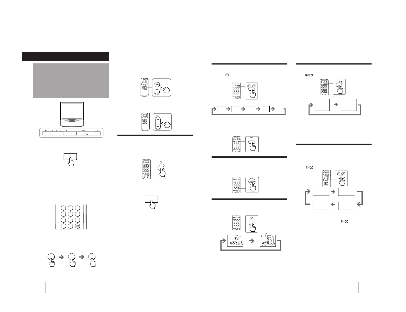
To scan through program positions
Press PROGR +/– on the remote commander or the
TV until the program position you want appears.
3
Press Á +/– on the remote commander or
the TV to adjust the volume.
Turning off the TV
To turn off the TV temporarily
Press u on the remote commander. The u/Â
indicator lights up.
To turn off the TV completely
Press U on the TV.
1
Press U to turn on the TV.
When the TV is turned on in the standby mode, the
u/Â indicator on the TV lights up. To turn on the
TV completely, press u on the remote commander
or the TV.
2
Select the TV program you want to watch.
To select a program position directly
Press the number button.
To select a two-digit program position, press “÷”
before the number buttons.
For example: to select program position 25, press
“÷,” then “2” and “5.”
PROGR
2
-/--
5
Operations
1
2
3
4
5
6
7
8
0
-/--
9
U
U
PROGR
R
19
-EN
Operations
Watching the video input
Press …
on the remote commander or … on
the TV.
To watch TV
Press ; on the remote commander or … on the TV.
Switching back quickly to the previous
channel
Press JUMP.
Muting the sound
Press ¤.
MUTING
POWER BASSO: ON
DYNAMIC
8
After 30 minutes
After 60 minutes
No Sleep Timer
After 90 minutes
SLEEP TIMER:30M
SLEEP TIMER:60M
SLEEP TIMER:OFF
SLEEP TIMER:90M
Displaying the on-screen information
Press .
Note
• The on-screen display shows the program position or the video
mode, the picture and sound information. The on-screen
display for the picture and sound information disappears after
being displayed for approximately three seconds.
Setting the Sleep Timer
You can set the TV to turn off automatically after the
period of time you want.
Press
.
To cancel the Sleep Timer, press
repeatedly until
“SLEEP TIMER: OFF” appears, or turn the TV off.
VIDEO 1 VIDEO 2
VIDEO 3
1
DVD
– 10 –

Operations
20
-EN
Selecting the picture and sound modes
1
Press MENU.
2
Make sure the cursor (”) appears in the A/V
CONTROL menu (
), and press ENTER.
3
Press V or v to move the cursor (”) to
DYNAMIC, STANDARD, SOFT, or PERSONAL,
and press ENTER.
Select To
DYNAMIC Receive high contrast picture with
powerful sound.
STANDARD Receive normal contrast picture with
medium listening sound.
SOFT Receive mild picture with soft sound.
PERSONAL Receive the last picture and sound
settings that are adjusted using VIDEO
ADJUST and AUDIO ADJUST.
4
Press MENU to return to the normal screen.
Adjusting the
picture and sound
MENU
ENTER
ENTER
ENTER
MENU
Press V/b
Increase picture
contrast.
Increase color
intensity.
Brighten the picture.
Make picture tones
become greenish.
Sharpen the picture.
Increase emphasis on
picture edges.
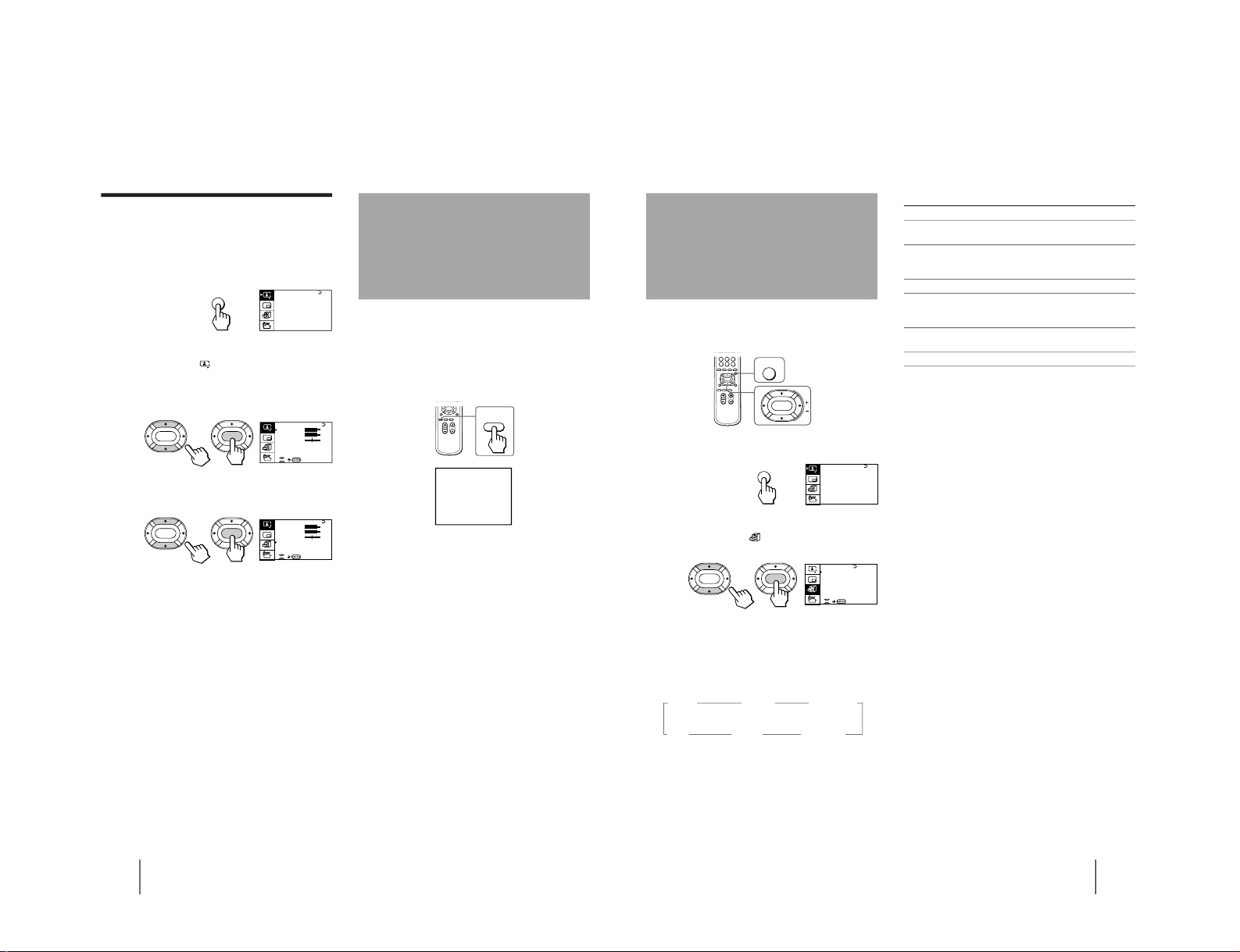
Adjusting the picture settings
(VIDEO ADJUST)
You can adjust the picture settings to suit your taste
with the VIDEO ADJUST option. The adjusted settings
are stored in the PERSONAL option.
1
Press MENU.
2
Make sure the cursor (”) appears in the A/V
CONTROL menu (
), and press ENTER.
3
Press V or v to move the cursor (”) to VIDEO
ADJUST, and press ENTER.
4
Press V or v to move the cursor (”) to the
item you want to adjust, and press ENTER.
5
Press V/b/v/B to adjust the selected item,
and press ENTER.
For details on each item, see “Description of adjustable
items” below.
6
To adjust other items, repeat steps 4 and 5.
7
Press MENU to return to the normal screen.
Description of adjustable items
Item Press v/B
PICTURE Decrease picture
contrast.
COLOR Decrease color
intensity.
BRIGHT Darken the picture.
HUE Make picture tones
become reddish.
SHARP Soften the picture.
VM Decrease emphasis
on picture edges.
Note
• You can adjust HUE for the NTSC color system only. (Note
that you can't adjust the NTSC color system of the component
inputs.)
A / V CONTROL
DYNAMIC
SOFT
STA NDARD
PERSONAL
V IDEO AD JUST
AUDI O AD JUST
MENU
A / V CONTROL
DYNAMIC
SOFT
STA NDARD
PERSONAL
V IDEO AD JUST
AUDI O AD JUST
MENU
P IC TURE
50
90
0
50
V IDEO ADJ UST
COLOR
BR IGHT
HUE
SHARP
VM: HIGH
50
0
ENTER
ENTER
21
-EN
Operations
Press V/b
Increase the bass
sound.
Increase the treble
sound.
Increase the right
speaker's volume.
If the picture is slightly snowy
You may try to improve the picture by changing the
VM setting as described below:
1 Display the VIDEO ADJUST menu.
2 Press V or v to move the cursor (”) to VM, and
press ENTER.
3 Press V/b/v/B to select LOW, and press ENTER.
If the picture color is abnormal when receiving
programs through the ˘ (antenna) terminal
Change the color system or the TV system from the
PRESET menu as described below until the color
becomes normal.
1 Display the PRESET menu.
2 Press V or v to move the cursor (”) to
COL SYS or TV SYS, and press ENTER.
3 Press V/b/v/B to change the color system or the
TV system until the color becomes normal, and
press ENTER.
Note
• Normally set the color system (COL SYS) to AUTO.
Adjusting the sound settings
(AUDIO ADJUST)
You can adjust the sound settings to suit your taste
with the AUDIO ADJUST option. The adjusted settings
are stored in the PERSONAL option.
1
Press MENU.
2
Make sure the cursor (”) appears in the A/V
CONTROL menu (
), and press ENTER.
3
Press V or v to move the cursor (”) to
AUDIO ADJUST, and press ENTER.
4
Press V or v to move the cursor (”) to the
item you want to adjust, and press ENTER.
5
Press V/b/v/B to adjust the selected item,
and press ENTER.
For details on each item, see “Description of adjustable
items” below.
6
To adjust other items, repeat steps 4 and 5.
7
Press MENU to return to the normal screen.
Description of adjustable items
Item Press v/B
BASS Decrease the bass
sound.
TREBLE Decrease the treble
sound.
BALANCE Increase the left
speaker's volume
If the sound is distorted or noisy when
receiving programs through the
(antenna)
terminal
Change the TV system from the PRESET menu as
described below until the sound becomes normal.
1 Display the PRESET menu.
2 Press V or v to move the cursor (”) to TV SYS, and
press ENTER.
3 Press V/b/v/B to change the TV system until the
sound becomes normal, and press ENTER.
A / V CONTROL
DYNAMIC
SOFT
STA NDARD
PERSONAL
V IDEO AD JUST
AUDI O AD JUST
MENU
BASS
80
00
80
TREBLE
BALANCE
AUDI O AD JUST
ENTER
ENTER
SPEAKER:
MAIN
– 11 –
Operations
22
-EN
Listening with
dynamic sound
(POWER BASSO)
The POWER BASSO sound mode enables you to enjoy
a high quality sound with the best combination of all
types of sound. It reproduces dynamic and clear
sounds and emphasizes low and high audio effects as
well.
Press POWER BASSO.
The sound mode of the TV program or the video input
changes to the POWER BASSO sound.
To cancel the POWER BASSO mode
Press POWER BASSO again.
Note
• You can select any of the surround sound modes (HYPER
SURROUND) to cancel the POWER BASSO sound.
POWER
BASSO
POWER BASSO: ON
Setting the speaker
If you connect a Dolby Pro Logic-compatible amplifier
to the center speaker terminals, you can use the
projection TV speakers as center speakers.
1
Press MENU.
2
Make sure the cursor (z) appears in the A/V
CONTROL menu (
), and press ENTER.
3
Press V or v to move the cursor (z) to
AUDIO ADJUST, and press ENTER.
4
Press V or v to move the cursor (z) to
SPEAKER, and press ENTER.
5
Press V/b/v/B to set the speaker, and press
ENTER.
To use the projection TV speakers as center
speakers, select CENTER IN.
To listen to the sound from a projection TV, select
MAIN.
6
Press MENU to return to the normal screen.
A / V CONTROL
DYNAMIC
SOFT
STA NDARD
PERSONAL
V IDEO AD JUST
AUDI O AD JUST
MENU
BASS
80
00
80
TREBLE
BALANCE
AUDI O AD JUST
ENTER ENTER
SPEAKER:
MAIN
BASS
80
00
80
TREBLE
BALANCE
AUDI O AD JUST
ENTER
ENTER
SPEAKER:
MAIN
23
-EN
Operations
The HYPER SURROUND feature enables you to enjoy
a surround sound effect that is like being in a concert
hall or movie theater when receiving stereo signals.
1
Press MENU.
2
Press V or v to move the cursor (z) to the
FEATURES menu (
) , and press ENTER.
3
Press V or v to move the cursor (z) to
HYPER SURROUND, and press ENTER.
4
Press V/b/v/B to select MOVIE, MUSIC,
NEWS〈BBE〉, HALL〈SRS〉 or SPACE, and press
ENTER.
MOVIE n
MUSIC nNEWS〈BBE
〉
OFF N SPACE N HALL
〈
SRS〉 N
For details on each item, see “Description of adjustable
items” below.
5
Press MENU to return to the normal screen.
Description of adjustable items
Select To
MOVIE Listen to a sound that emphasizes the bass
audio effect of movie theater.
MUSIC Listen to a dynamic and clear sound that
emphasizes the low and high audio
sounds.
NEWS〈BBE〉 Listen to a sound that emphasizes voice.
HALL〈SRS〉 Listen to a sound that spreads out over a
large area, giving the feeling of being at a
concert hall.
SPACE Listen to a monaural sound that gives a
stereo-like effect.
OFF Turn off the surround sound.
Notes
• The BBE is manufactured by Sony Corporation under license
from BBE Sound, Inc. It is covered by U.S. Patent No. 4,638,258
and No. 4,482,866. The word “BBE” and the BBE symbol are
the trademarks of BBE Sound, Inc.
• The (r)
®
SRS (SOUND RETRIEVAL SYSTEM) is manufactured
by Sony Corporation under license from SRS Labs, Inc. It is
covered by U.S. Patent No. 4,748,669.
The word “SRS” and the SRS symbol (r) are registered
trademarks of SRS Labs, Inc.
Listening to the
surround sound
(HYPER SURROUND)
MENU
ENTER
A / V CONTROL
DYNAMIC
SOFT
STA NDARD
PERSONAL
V IDEO AD JUST
AUDI O AD JUST
MENU
GAME MODE
HYPER SURROUND :
OFF
MONITOR
AV OUT:
FE ATURES
ENTER ENTER
CONVERGENCE
– 12 –
Operations
24
-EN
On-screen display
(Selected sound)
You can enjoy stereo sound or bilingual programs of
NICAM and A2 (German) stereo systems.
Press A/B
repeatedly until you receive the
sound you want.
The on-screen display changes corresponding to the
selected sound and the u/Â indicator also lights up.
When receiving a NICAM program
Broadcasting
NICAM stereo n
NICAM
n
MONO
(Stereo sound) (Regular sound)
NICAM bilingual n
NICAMn NICAM
n
MONO
MAIN SUB (Regular sound)
(Main sound) (Sub sound)
NICAM monaural n
NICAM
n
MONO
MAIN (Regular sound)
(Main sound)
When receiving an A2 (German) program
Broadcasting
A2 (German)
stereo
A2 (German)
bilingual
Receiving area for NICAM and A2 (German)
programs
System Receiving area
NICAM Hong Kong, Singapore, New Zealand,
Malaysia, Thailand, etc.
A2 (German) Australia, Malaysia, Thailand, etc.
Notes
• If the signal is very weak, the sound becomes monaural.
• If the stereo sound is noisy when receiving a NICAM program,
select “MONO.” The sound becomes monaural, but the noise is
reduced.
If the sound is distorted or noisy when
receiving a monaural program through the ˘
(antenna) terminal
Press A/B
repeatedly until “MONO” appears on the
screen while the u/Â indicator is off.
To cancel the monaural sound setting, press A/B
again until “AUTO” appears on the screen.
Notes
• The “MONO” or “AUTO” setting memorized for each
program position.
• You cannot receive stereo broadcast signal when the TV is in
the “MONO” setting.
Selecting a stereo or
bilingual program
On-screen display
(Selected sound)
A/B
n
MAIN
n
SUB
(Main sound) (Sub sound)
n
MONO
n
STEREO
(Regular sound) (Stereo sound)
n
MONO
n
AUTO
25
-EN
Operations
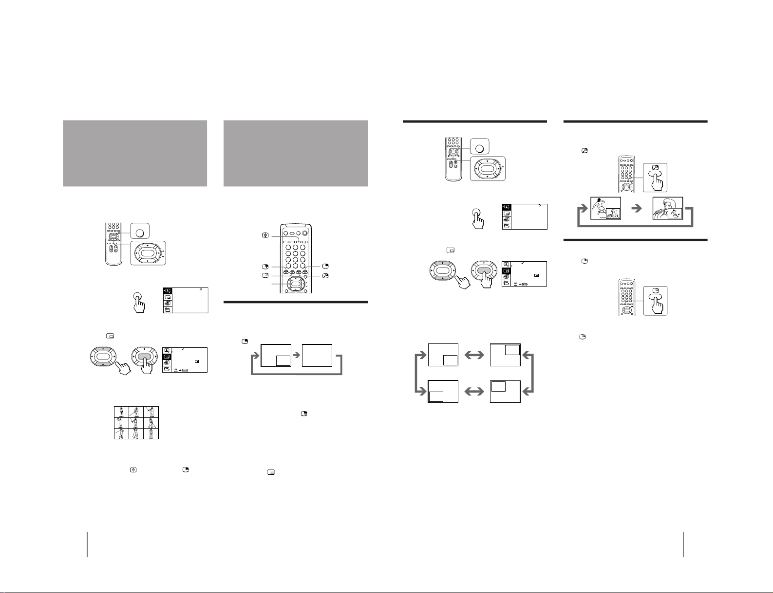
To restore the normal screen
Press PROGR INDEX again or
.
You can also select PROGR INDEX or PIP : OFF from
the PIP menu, and press ENTER to restore the normal
screen.
To view multiple programs on the nine sub
screens using the menu
1
Press MENU.
2
Press V or v to move the cursor (z) to the
PIP menu (
), and press ENTER.
3
Make sure the cursor (z) appears beside
PROGR INDEX, and press ENTER.
Notes
• You can change the position of the nine sub screens using the
PIP menu (see “Changing the position of the PIP screen” on
page 27).
• You can hear the sound of the main screen when viewing
multiple programs on the nine sub screens.
• You can use the number buttons on the remote commander to
change the program position of the main screen when viewing
multiple programs on the nine sub screens.
Viewing multiple
programs at the
same time
(PROGRAM INDEX)
The PROGRAM INDEX feature allows you to view all
the preset TV programs and the video inputs on the
nine sub screens at the same time.
You can view multiple programs on the nine sub
screens using the button on the remote commander or
the menu.
Press PROGR INDEX.
The first nine preset programs appear on the nine sub
screens.
To view the next or the previous nine preset
programs on the nine sub screens
Press PROGR +/– on the remote commander or the TV.
To select the program you want to watch
directly after viewing multiple programs
Press the number buttons, …
, or press
V/b/v/B to move the cursor (>>>) to the screen of the
program you want to watch, and press ENTER.
PROGR
INDEX
123
456
789
>>>
123
456
789
10 11 12
V1 V2 V3
123
>>> >>>
PIP
PIP: OFF
PIP TEXT
STROBE
POSI T I ON:
PROGR I ND EX
ENTER ENTER
A / V CONTROL
DYNAMIC
SOFT
STA NDARD
PERSONAL
V IDEO AD JUST
AUDI O AD JUST
MENU
– 13 –
Operations
26
-EN
With the Picture-in-Picture (PIP) feature, you can
display a sub screen within the main picture of
different TV programs or video inputs.
Displaying the PIP screen
You can display the PIP screen using the button on the
remote commander or the menu.
Press
.
Selecting a TV program or video input in the
PIP screen
To select a TV program, press V or v, and press
ENTER.
To select a video input, press
on the remote
commander or … on the TV.
To display the PIP screen using the menu
1
Press MENU.
2
Press V or v to move the cursor (”) to the
PIP menu (
), and press ENTER.
3
Press V or v to move the cursor (”) to PIP,
and press ENTER.
4
Press V/b/v/B to select ON, and press ENTER.
5
Press MENU to return to the normal screen.
Using the Picture-inPicture (PIP)
features
Displaying frameby-frame pictures
(STROBE)
You can watch a slow motion movement of the main
screen picture which is displayed frame-by-frame on
the nine sub screens.
1
Press MENU.
2
Press V or v to move the cursor (z) to the
PIP menu (
), and press ENTER.
3
Press V or v to move the cursor (z) to
STROBE, and press ENTER.
To restore the normal screen
Select STROBE again or PIP : OFF from the PIP menu,
and press ENTER.
You can also press ;, …
, PROGR +/–, or
to
restore the normal screen.
Notes
• You can change the position of the nine sub screens using the
PIP menu (see "Changing the position of the PIP screen" on
page 27).
• You can hear the normal sound when using the STROBE
feature.
MENU
ENTER
PIP
PIP: OFF
PIP TEXT
STROBE
POSI T I ON:
PROGR IND EX
ENTER ENTER
;
…
V/v/ENTER
1
2
3
4
5
6
7
8
0
9
A / V CONTROL
DYNAMIC
SOFT
STA NDARD
PERSONAL
V IDEO AD JUST
AUDI O AD JUST
MENU
27
-EN
Operations
Swapping pictures between the main
and PIP screens
Press
.
Freezing the PIP screen
Press .
The PIP screen will freeze.
To restore the normal screen
Press
again.
Notes
• When you display a video input on the PIP screen at any speed
other than the normal one, the picture may be disrupted,
depending on the VCR.
• If you display different color systems on the main screen and
the PIP screen, the size of the PIP screen may be different and
the PIP picture may be disrupted. This does not indicate a
malfunction of the TV.
Changing the position of the PIP screen
1
Press MENU.
2
Press V or v to move the cursor (”) to the
PIP menu (
), and press ENTER.
3
Press V or v to move the cursor (z) to
POSITION, and press ENTER.
4
Press V/b/v/B to select the position you
want, and press ENTER.
5
Press MENU to return to the normal screen.
PIP
PIP: OFF
PIP TEXT
STROBE
POSI T I ON:
PROGR IND EX
ENTER ENTER
MENU
ENTER
A / V CONTROL
DYNAMIC
SOFT
STA NDARD
PERSONAL
V IDEO AD JUST
AUDI O AD JUST
MENU
– 14 –
Operations
28
-EN
TV stations broadcast an information service called
Teletext via a TV channel.
Teletext service allows you to receive various
information such as weather forecasts or news at any
time.
Displaying Teletext
1
Select a TV channel that carries the Teletext
broadcast you want to watch.
2
Press
to display the Teletext.
A Teletext page (normally the index page) is
displayed. If there is no Teletext broadcast, “100” is
displayed at the top left corner of the screen.
To turn off Teletext
Press ;.
Superimposing a Teletext page on the
TV picture
Press
.
Each time you press
, the screen changes as follows:
n Teletext n Teletext and TV n TV
Viewing Teletext
Checking the contents of a Teletext
service (INDEX)
Press to display an overview of the Teletext
contents and page numbers.
Using FASTEXT
This feature allows you to quickly access a Teletext
page that uses FASTEXT. When a FASTEXT program is
broadcasted, the colored menus appear at the bottom of
the screen. The colors of the menus correspond to the
red (
), green (
), yellow ( ), and blue (
)
colored-coded buttons on the remote commander.
To access a FASTEXT menu
Press the color-coded button on the remote commander
that corresponds to the colored menu which appears at
the bottom of the screen. The menu page appears on
the screen after several seconds.
Selecting a Teletext page
Press the number buttons to enter the threedigit page number of the Teletext page you
want.
If you make a mistake, re-enter the correct page
number.
To access the next or previous page
Press PROGR +/–.
You can also access a Teletext page of any page
numbers that appear in the colored column at the
bottom of the screen using the corresponding colorcoded button on the remote commander.
Holding a Teletext page (HOLD)
A Teletext page may consist of several subpages. You
can stop the page scrolling in order to read the text at
your own pace.
Press
.
The HOLD symbol “H” appears at the top left corner
of the screen.
To resume normal Teletext operation
Press
again or .
;
Number
PROGR +/–
Green
Red
Yellow
Blue
1
2
3
4
5
6
7
8
0
9
29
-EN
Operations
Revealing concealed information
(REVEAL)
The REVEAL option lets you disclose concealed
information, such as an answer to a quiz that you find
on some of the Teletext pages.
Press
.
To conceal the information
Press
again.
Enlarging the Teletext display
(ENLARGE)
Press .
Each time you press
, the Teletext display changes as
follows:
n Enlarge upper half n Enlarge lower half
Normal size N
Waiting for a Teletext page while
watching a TV program (TEXT CLEAR)
1
Enter the page number of the Teletext that
you want to refer to, then press
.
2
When the page number is displayed on the
screen, press
to turn on the Teletext.
– 15 –
Operations
30
-EN
To display a Teletext page on the PIP screen
using the menu
1
Press MENU.
2
Press V or v to move the cursor (z) to the
PIP menu (
) , and press ENTER.
3
Press V or v to move the cursor (z) to PIP
TEXT, and press ENTER.
4
Press V/b/v/B to select the Teletext page you
want to watch.
Notes
• You can also use the color-coded buttons (see page 28) while
displaying a Teletext page on the PIP screen.
• To select a Teletext page on the PIP screen, press V/b/v/B
once only.
If you press V/b/v/B continuously, the Teletext page
numbers also change continuously at a fast speed.
• You can change the position of a Teletext page on the PIP
screen using the PIP menu (see "Changing the position of the
PIP screen" on page 27).
PIP
PIP: OFF
PIP TEXT
STROBE
POSI T I ON:
PROGR IND EX
ENTER
ENTER
MENU
ENTER
The PIP TEXT feature enables you to display a Teletext
page on the PIP screen while watching a TV program.
You can display the Teletext on the PIP screen using
the button on the remote commander or the menu.
1
Select a TV channel that carries the Teletext
broadcast you want to watch.
2
Press PIP TEXT.
To restore the normal screen
Press PIP TEXT again, or press ;, …
, or PROGR
+/–.
You can also select PIP : OFF from the PIP menu, and
press ENTER to restore the normal screen.
Displaying Teletext
on the PIP screen
(PIP TEXT)
PIP
TEXT
P166 SECTEXT 166 FR1 MAR 03:59:09
Fom Singapore
To PARIS
To OSAKA
To ROMA
To SYDNEY
Day Dep/Arr Flight Alrcraft
1.6 220/0588 SQ28 747
2 2130/1225 PA115 L15
3 2115/1330 SQ26 747
2.7 2130/0745 SQ24
747
4 2300/0915 AZ487 747
2.5 1000/1715 SQ6 747
4.6 0930/2015 CX522 L10
1 2210/0610 SQ21A 747
2 2100/0835 SQ21A 747
A / V CONTROL
DYNAMIC
SOFT
STA NDARD
PERSONAL
V IDEO AD JUST
AUDI O AD JUST
MENU
31
-EN
Operations
To restore the normal picture and sound
modes
Press ;, …
, or PROGR +/–.
Notes
• If you press the GAME button when the TV is in the standby
mode, the TV turns on automatically and the picture and
sound change to the mode that is suitable for video games.
• To display a video game screen, connect the video game
equipment to the … 3 (video input) jacks at the front or the
rear of the TV.
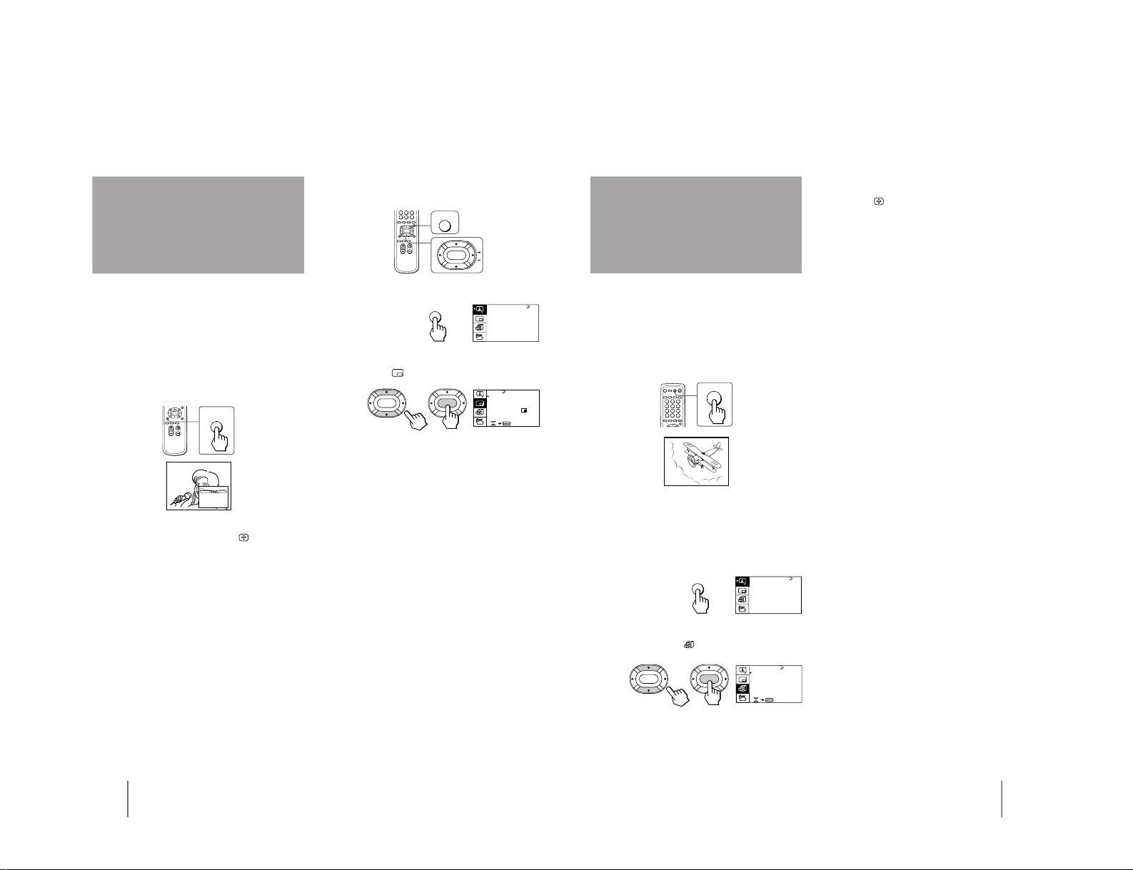
The GAME MODE feature optimizes the video game
screen by giving a soft picture and dynamic sound
effect.
You can display a video game screen using the button
on the remote commander or the menu.
Press GAME.
The picture and sound change to the mode that is
suitable for video games.
To view a video game screen using the menu
1
Press MENU.
2
Press V or v to move the cursor (z) to the
FEATURES menu (
), and press ENTER.
3
Make sure the cursor (z) appears beside
GAME MODE, and press ENTER.
Viewing a video
game screen
(GAME MODE)
GAME
GAME
A / V CONTROL
DYNAMIC
SOFT
STA NDARD
PERSONAL
V IDEO AD JUST
AUDI O AD JUST
MENU
GAME MODE
HYPER SURROUND :
OFF
MONITOR
AV OUT:
FE ATURES
ENTER ENTER
CONVERGENCE
– 16 –
Operations
32
-EN
Customizing the TV
Using the AV OUT (advanced rec-out)
terminal
You can select the output signal from the Ú (monitor/
TV output) jacks at the rear of the TV. However, the
signals of the PROGRAM INDEX, STROBE, PIP modes,
the signals from the
(component video input)
jacks, and the Teletext broadcast cannot be output even
though MONITOR is selected.
1
Press MENU.
2
Press V or v to move the cursor (z) to the
FEATURES menu (
), and press ENTER.
3
Press V or v to move the cursor (z) to AV
OUT, and press ENTER.
4
Press V/b/v/B to select the output signal,
and press ENTER.
Select To
TV Output the signal of the TV broadcast.
MONITOR Output the signal of the picture you are
watching as a main picture.
Notes
• Do not change the channel while recording with a VCR
through the Ú (monitor/TV output) jacks. If you change the
channel, it also changes the channel you are recording.
• When the signals from the
(component video input) jacks
are displayed on the main screen, the signals can't be output
even though MONITOR is selected.
A / V CONTROL
DYNAMIC
SOFT
STA NDARD
PERSONAL
V IDEO AD JUST
AUDI O AD JUST
MENU
GAME MODE
HYPER SURROUND :
OFF
MONITOR
AV OUT:
FE ATURES
ENTER
ENTER
CONVERGENCE
33
-EN
Additional Information
If you have any problems, read this manual again and
check the countermeasure for each of the symptoms
listed below.
If the problem persists, contact your nearest Sony
dealer or authorized service center.
Snowy picture
Noisy sound
/ Check the antenna.
/ Check the antenna connection on the TV
and on the wall.
/ Check the TV system (TV SYS) setting.
/ Check the ATT (attenuator) setting.
Dotted lines or stripes
/ This may be caused by local interference
(e.g. cars, neon signs, hair dryers, etc.).
Adjust the antenna for minimum
interference.
Double images or “ghosts”
/ This may be caused by reflections from
nearby mountains or buildings. A highly
directional antenna may improve the
picture.
Troubleshooting
Good picture
Noisy sound
/ Check the TV system (TV SYS) setting.
No picture
No sound
/ Press u.
/ Press U to turn off the TV for about five
seconds and then turn it on again.
/ Check the power cord connection.
/ Check the antenna connection.
/ Check the VCR connections.
Good picture
No sound
/ Press Á +.
/ If “CENTER IN” is displayed on the
screen, select “SPEAKER: MAIN” of the
AUDIO ADJUST menu.
/ Press ¤.
/ Press A/B
.
No color
/ Adjust the COLOR level in the VIDEO
ADJUST menu of the PERSONAL option.
/ Check the color system (COL SYS) setting.
TV cannot receive stereo broadcast signal
/ Press A/B
until “AUTO” appears on
the screen.
TV cabinet creaks
/ Even if the picture or the sound is normal,
changes in the room temperature
sometimes make the TV cabinet expand or
contract, making a noise. This does not
indicate a malfunction.
Additional Information
Additional Information
– 17 –

KP-EF41HK2/ME2/MN2/SN2, EF48HK2/ME2/MN2/SN2,
KP-EF53HK2/ME2/MN2/SN2 RM-871
MEMO
– 18 –
KP-EF41HK2/ME2/MN2/SN2, EF48HK2/ME2/MN2/SN2,
KP-EF53HK2/ME2/MN2/SN2 RM-871
SECTION 2
DISASSEMBLY
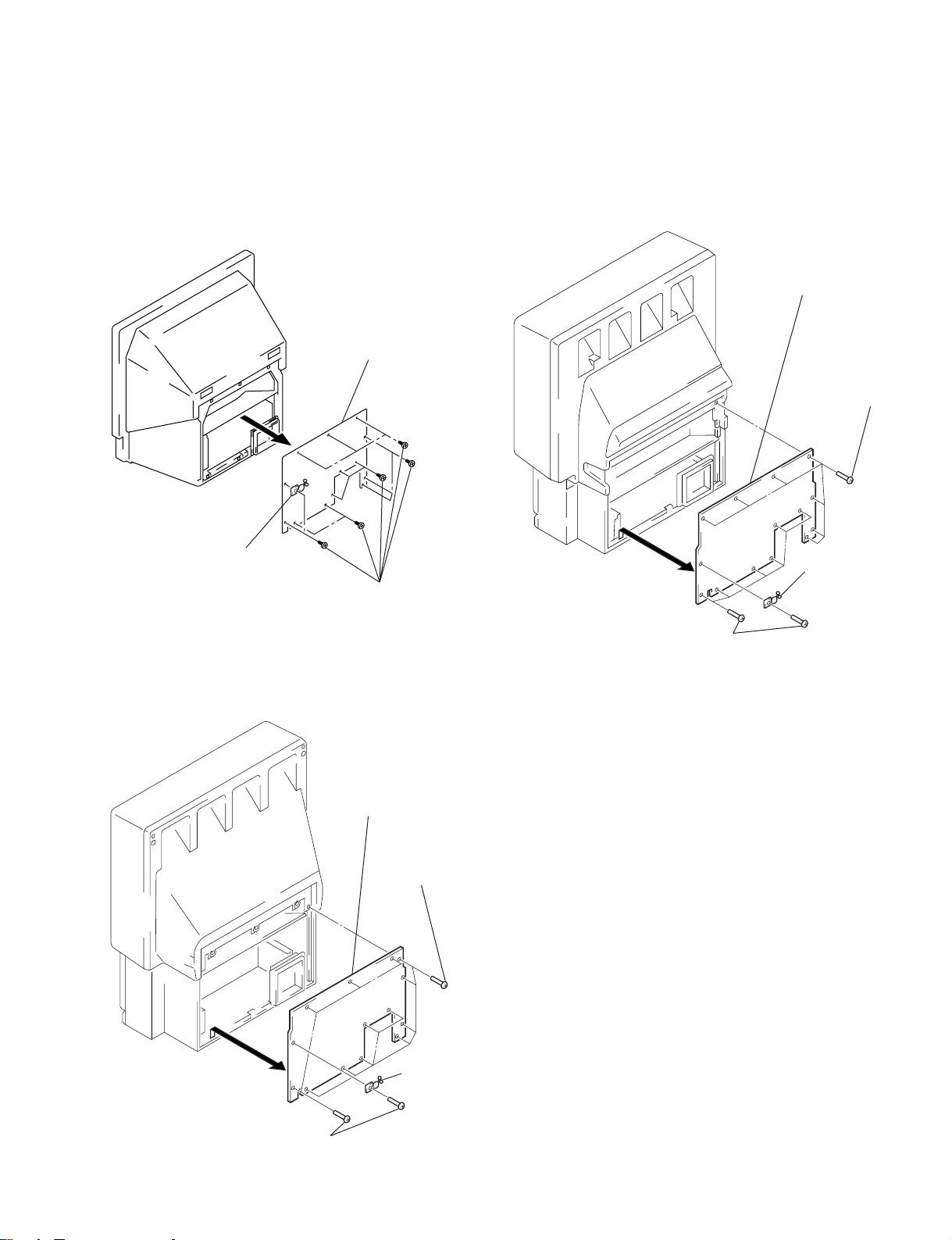
2-1. REAR BOARD REMOVAL
• KP-EF41 • KP-EF53
2 Rear board
4 Rear board
1 Seven screws
(Hexagon head)
• KP-EF48
3 Purse
lock
1 Thirteen screws
(Hexagon head)
4 Rear board
1 Nine screws
3 Purse
lock
2 Seven screws
(Hexagon head)
(Hexagon head)
2 Five screws
(Hexagon head)
3 Purse
lock
– 19 –
KP-EF41HK2/ME2/MN2/SN2, EF48HK2/ME2/MN2/SN2,
KP-EF53HK2/ME2/MN2/SN2 RM-871
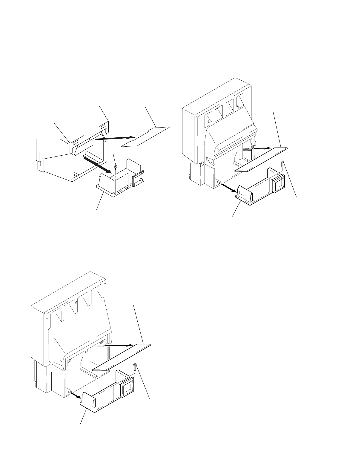
2-2. MAIN BRACKET SECTION REMOVAL
• KP-EF41 • KP-EF53
1 Optical shield
2 Two screws
(BVTP 4X16)
1 Light
interception
plate
• KP-EF48
2 Two screws
(Hexagon head)
3 Main bracket section
3 Main bracket section
1 Light
interception
plate
3 Main bracket section
2 Two screws
(Hexagon head)
– 20 –
KP-EF41HK2/ME2/MN2/SN2, EF48HK2/ME2/MN2/SN2,
KP-EF53HK2/ME2/MN2/SN2 RM-871
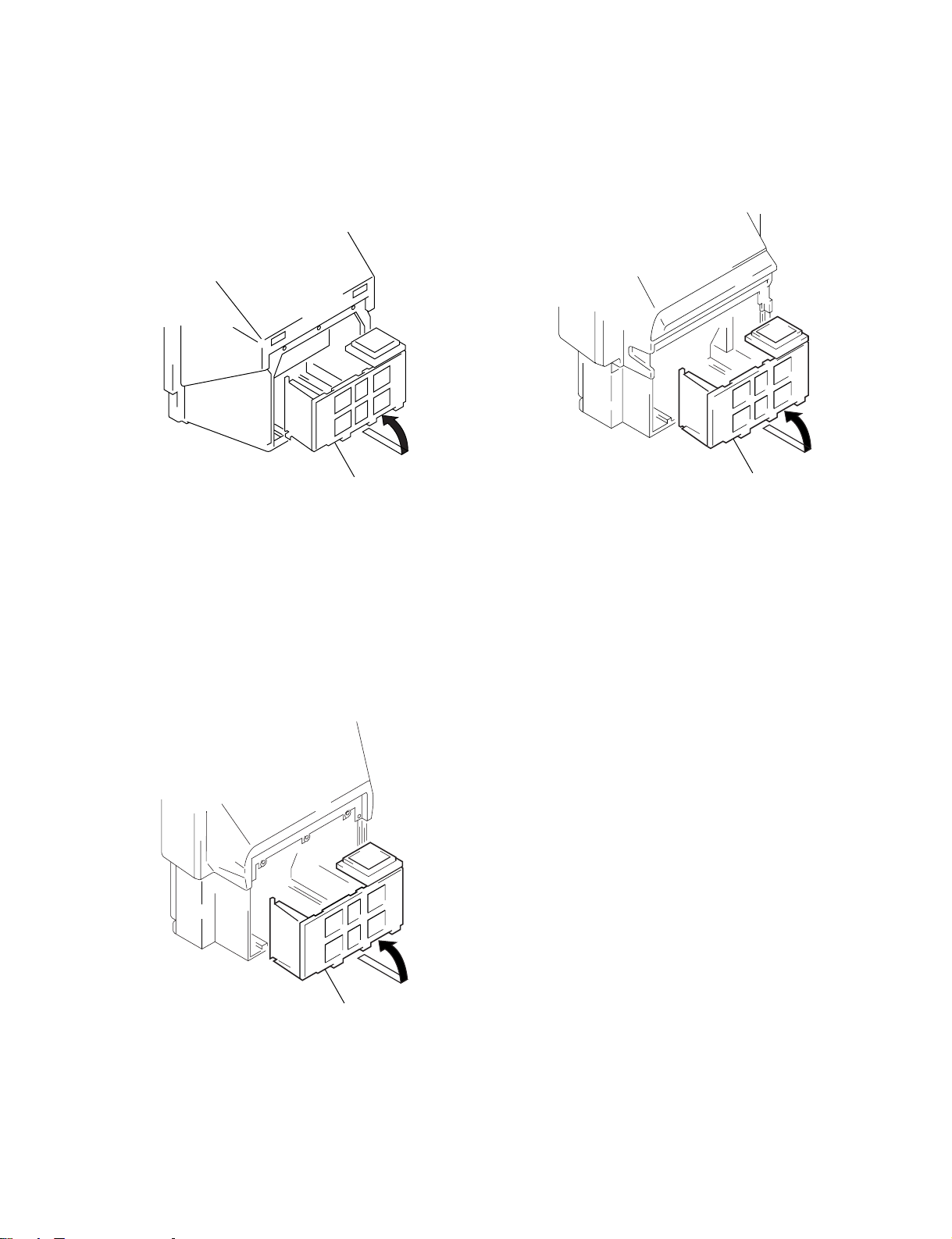
2-3. SERVICE POSITION
• KP-EF41 • KP-EF53
• KP-EF48
Main bracket section
Main bracket section
Main bracket section
– 21 –

KP-EF41HK2/ME2/MN2/SN2, EF48HK2/ME2/MN2/SN2,
KP-EF53HK2/ME2/MN2/SN2 RM-871
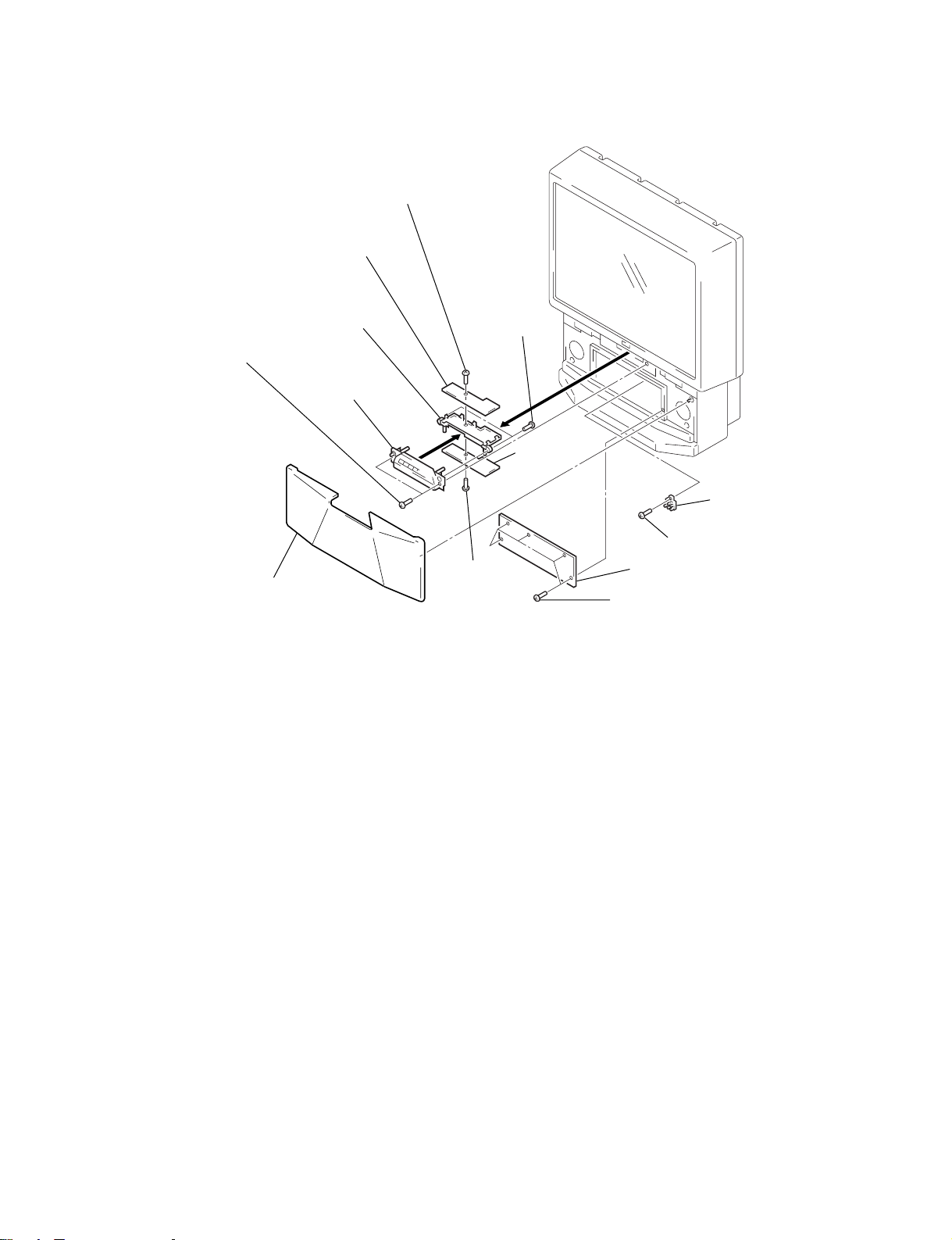
2-4. H1 BOARD, H2 BOARD AND RESISTOR (HIGH VOLTAGE) REMOVAL
• KP-EF41
8 Screw
(BVTP 3X12)
9 H1 board
7 Bracket (H)
!¡ H2 board
5 Control panel ass’y
4 Two screws
(BVTP 4X16)
!£ Resistor (Hight voltage)
!™ Screw (BVTP 4X16)
6 Two screws (BVTP 4X16)
0 Screw (BVTP 3X12)
1 Speaker grille
3 Front board
• KP-EF48
2 Two screws
7 H1 board
5 Bracket (H)
(Hexagon head)
6 Screw
3 Control panel
ass’y
2 Five screws
(Hexagon head)
4 Two screws
(BVTP 4X16)
(BVTP 3X12)
8 Screw
(BVTP 3X12)
9 H2 board
!£ Resistor
(High voltage)
!™ Screw (BVTP 4X16)
1 Speaker grille
!¡ Front board
0 Five screws
(Hexagon head)
– 22 –
KP-EF41HK2/ME2/MN2/SN2, EF48HK2/ME2/MN2/SN2,
KP-EF53HK2/ME2/MN2/SN2 RM-871
• KP-EF53
2 Two screws
(Hexagon head)
1 Speaker grille
6 Screw
7 H1 board
5 Bracket (H)
3 Control
panel ass’y
(BVTP 3X12)
8 Screw
4 Two screws
(BVTP 4X16)
9 H2 board
!£ Resistor
(High voltage)
!™ Screw (BVTP 4X16)
!¡ Front board
(BVTP 3X12)
0 Five screws
(Hexagon head)
– 23 –

KP-EF41HK2/ME2/MN2/SN2, EF48HK2/ME2/MN2/SN2,
KP-EF53HK2/ME2/MN2/SN2 RM-871
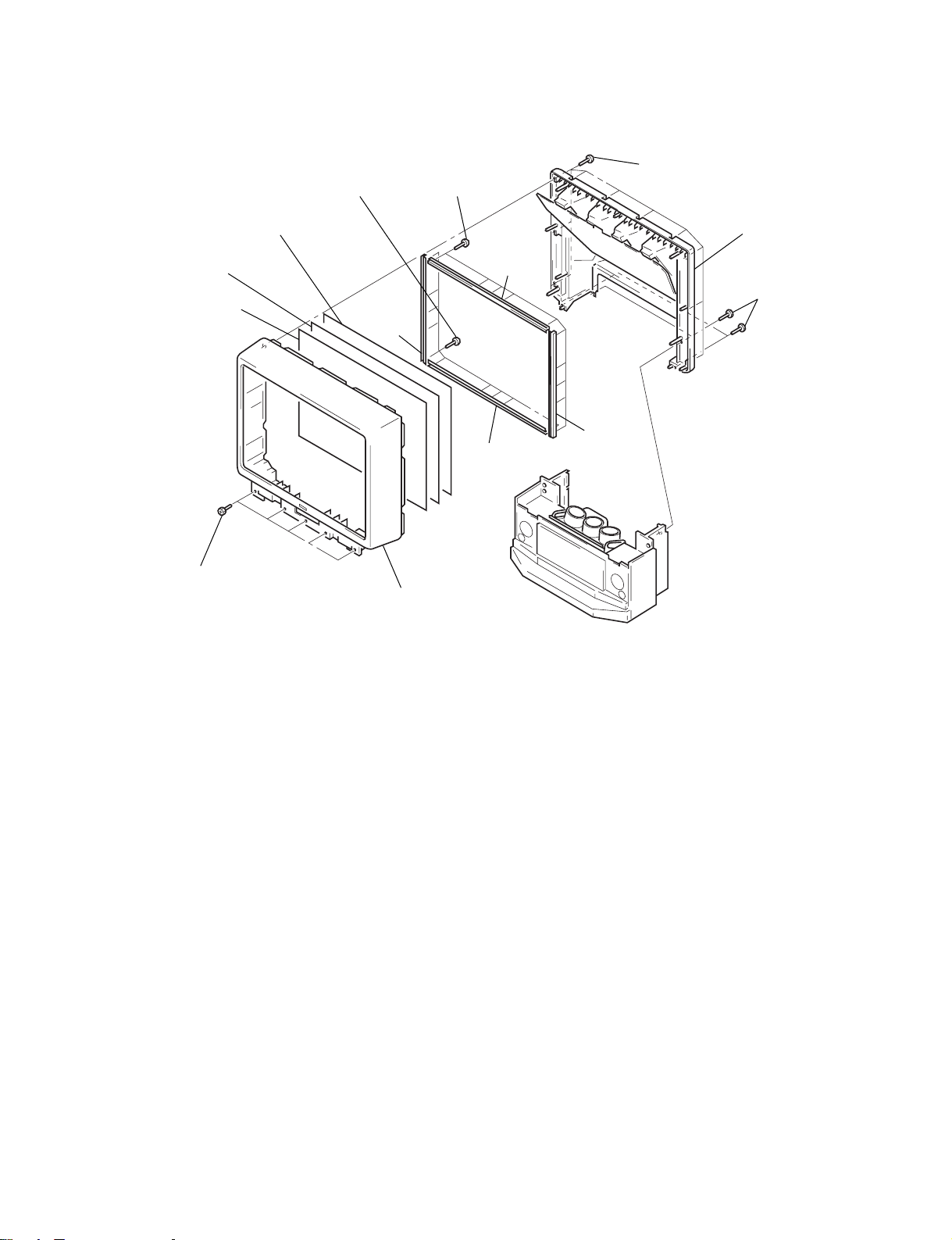
2-5. BEZNET SECTION REMOVAL
• KP-EF41
!¡ Screen holder (V)
!™ Diffusion plate (F)
!£ Diffusion plate (L)
!¢ Contrast screen
4 Beznet ass’y
3 Four screws
7 Eight screws
(BVTP 4X16)
5 Four screws
(BVTP 4X12)
(BVTP 4X12)
8 Screen holder (H)
0 Screen holder (H)
2 Seven screws
(BVTP 4X16)
!∞ Mirror cover
6 Four screws
(BVTP 4X12)
9 Screen holder (V)
1 Four screws
(BVTP 4X16)
• KP-EF48
!™ Contrast screen
3 Beznet ass’y
7 Ten screws
!¡ Diffusion plate (L)
0 Diffusion plate
(F)
(BVTP 4X12)
8 Screen
holder (V)
4 Ten screws
(BVTP 4X12)
5 Screen
holder (H)
9 Screen
holder (H)
2 Ten screws
(BVTP 4X16)
!¢ Mirror cover
!£ Four screws
(Hexagon head)
6 Screen
holder (V)
1 Four screws
(Hexagon head)
– 24 –
KP-EF41HK2/ME2/MN2/SN2, EF48HK2/ME2/MN2/SN2,
KP-EF53HK2/ME2/MN2/SN2 RM-871
• KP-EF53
!¡ Diffusion plate (L)
!™ Contrast screen
1 Four screws
(Hexagon head)
0 Diffusion
plate (F)
7 Ten screws
(BVTP 4X12)
8 Screen
4 Ten screws
(BVTP 4X12)
holder
(V)
3 Beznet
ass’y
5 Screen
holder
(H)
9 Screen holder
(H)
2 Ten screws
(BVTP 4X16)
!¢ Mirror cover
!£ Four screws
(Hexagon head)
6 Screen
holder
(V)
– 25 –

KP-EF41HK2/ME2/MN2/SN2, EF48HK2/ME2/MN2/SN2,
KP-EF53HK2/ME2/MN2/SN2 RM-871
2-6. G BOARD REMOVAL 2-7. P1 BOARD AND V2 BOARD
REMOVAL
1 Three holder PWB
1 Two claws
2 G Board
2-8. UG BOARD, AG BOARD AND S BOARD REMOVAL
3 Two claws
4 V2 board
2 P1 board
0 AG board
!¡ S board
1 SW screws
(M3X10)
7 Bracket (A)
8 Two claws
9 UG board
6 Claw
5 Terminal board
(GA)
4 Screw
(BVTP 4X16)
2 Six screws
(BVTP 3X12)
3 Two screws
(BVTP 4X16)
– 26 –

KP-EF41HK2/ME2/MN2/SN2, EF48HK2/ME2/MN2/SN2,
KP-EF53HK2/ME2/MN2/SN2 RM-871
2-9. HIGH-VOLTAGE CABLE INSTALLATION AND REMOVAL
(1) Remover
1 Rubber cap
2 HV cable
turn 90°
2-10. MECHASEL ASSY REMOVAL
Removing the arrow-marked screw is strictly inhibited.
If removed, it may cause liquid spill.
(2) Installation
2 Rubber cap
1 HV cable
Hook
Gutter
1 Four screws
(BVTP 4X16)
5 Four screws
(BVTP 4X16)
6 Mechaseal assy (R)
4 Deflection yoke
3 Neck assy
2 CR board
7 Extension spring
– 27 –

KP-EF41HK2/ME2/MN2/SN2, EF48HK2/ME2/MN2/SN2,
KP-EF53HK2/ME2/MN2/SN2 RM-871
2-11. CHASSIS BLOCK REMOVAL
(1) H1, H2 BOARDS AND RESISTOR REMOVAL
• KP-EF41
4 Four connectors
1 Two screws
(BVTP 4X16)
2 Control panel ass’y
6 Resister (High voltage)
5 Screw
(BVTP 4X16)
3 Three connectors
• KP-EF53
4 Four
connectors
1 Two screws
(Hexagon head)
3 Three
2 Control panel
ass’y
5 Screw
connectors
6 Resistor
(High voltage)
(BVTP 4X16)
• KP-EF48
4 Four
connectors
1 Two screws
(Hexagon head)
3 Three connectors
2 Control panel
ass’y
5 Screw
(BVTP 4X16)
6 Resistor
(High voltage)
– 28 –

KP-EF41HK2/ME2/MN2/SN2, EF48HK2/ME2/MN2/SN2,
KP-EF53HK2/ME2/MN2/SN2 RM-871
(2) MAIN BRACKET REMOVAL
* Pay particular attention to the wires of each PCB when puling out the main bracket.
• KP-EF41
3 Set the main
bracket.
• KP-EF48
2 Pull the main
bracket.
1 Two screws
(Hexagon head)
• KP-EF53
1 Two screws
(Hexagon head)
3 Set the main
bracket.
2 Pull the main
bracket.
3 Set the main
bracket.
1 Two screws
(Hexagon head)
2 Pull the main
bracket.
– 29 –

KP-EF41HK2/ME2/MN2/SN2, EF48HK2/ME2/MN2/SN2,
KP-EF53HK2/ME2/MN2/SN2 RM-871
(3) CHASSIS BLOCK REMOVAL
* Pull out the chassis block by gripping the handles as shown in the diagram.
At this time, pay particular attention to the components removed in (1).
• KP-EF41
• KP-EF48
2 Pull the chassis
block.
1 Six screws
(Hexagon head)
• KP-EF53
2 Pull the chassis
block.
1 Six screws
(Hexagon head)
2 Pull the chassis
block.
1 Six screws
(Hexagon head)
– 30 –
 Loading...