

Sony KP-61V75 - 61"" Color Rear Video Projector, KP-48V75, KP-53V75, KP-53V75C Operating Instructions Manual
Color Rear Video
Projector
Operating Instructions
Manual de instrucciones
IMPORTANT SAFETY INFORMATION:
Please read the important safety information on page 2"EN.
INFORMACION IMPORTANTE SOBRE SEGURIDAD:
Lea la informaci6n importante sobre seguridad de la p_gina 2"Es.
CONSIGNES DE SECURITE IMPORTANTES:
Veuillez lire les informations concemant la s_curit_ _ la page 2"EN.
KP-48V75
KP-53V75
KP-53V75C
KP-61 V75
© 1998 by Sony Corporation
To
ex
)revent fire or shock hazard, do not
)ose the unit to rain or moisture.
RISK OF ELECTRIC SHOCK
DO NOT OPEN
ATTENTION
RISQUE DE CHOC ELECTRIQUE,
NE PAS OUVRIR
PRECAUCION
RIESGO DE CHOQUE ELECTRICO
NO ABRIR
CAUTION : TO REDUCE THE RISK OF ELECTRIC SHOCK,
DO NOT REMOVE COVER (OR BACK).
NO USER-SERVICEABLE PARTS INSIDE.
REFER SERVICING TO QUALIFIED SERVICE PERSONNEL.
This symbol is intended to alert the user to the
presence of uninsulated "dangerous voltage"
within the product's enclosure that may be of
sufficient magnitude to constitute a risk of
electric shock to persons.
This symbol is intended to alert the user to the
presence of important operating and
maintenance (servicing) instructions in the
literature accompanying the appliance.
CAUTION
To prevent electric shock, do not use this polarized AC plug
with an extension cord, receptacle or other outlet unless the
blades can be fully inserted to prevent blade exposure.
CAUTION
When using TV games, computers, and similar products with
your projection TV, keep the brightness and contrast
functions at low settings. If a fixed (non-moving} pattern is
left on the screen for long periods of time at a high brightness"
or contrast setting, the image can be permanently imprinted
onto the screen. These types of imprints are not covered by
. --your warranty because they are the result of misuse.
Note on Caption Vision
T-his television receiver provides display of television closed
captioning in accordance with §15.119 of the FCC rules.
Note on CATV system installer
This reminder is provided to call the CATV system installer's
attention to Article 820-40 of the NEC that provides
guidelines for proper grounding and, in particular, specifies
that the cable ground shall be connected to the grounding
system of the building, asclose to the point of _ble-entry as
practical.
Use of this television receiver for other than private viewing
of programs broadcast on UHF or VHF or transmitted by
cable companies for the use of the general public may require
authorization from the broadcaster, cable company and / or
program owner.
Note on convergence adjustment
Before you useyour projection TV, make sure to adjust
convergence. For the procedure, seepage 21.
NOTIFICATION
This equipment has been tested and found to comply with
the limits for a Class B digital device pursuant to Part 15 of
the FCC Rules. These limits are designed to provide
reasonable protection against harmhfl interference in a
residential installation. This equipment generates, uses, and
can radiate radio frequency energy and, if not installed and
used in accordance with the instructions, may cause harmful
inteference with radio communications. However, there is no
guarantee that interference will not occur in a particular
installation. If this equipment does cause harmful
interference to radio or television reception, which can be
determined by turning the equipment off and on, the user is
encouraged to try to correct the interference by one or more
of the following measures:
- Reorient or relocate the receiving antennas
- Increase the separation between the equipment and
receiver.
- Connect the equipment into an outlet on a circuit different
from that to which the receiver is connected.
- Consult the dealer or an experienced radio/TV technician
for help.
You are cautioned that any changes or modifications not
expressly approved in this manual could void your
authority to operate this equipment.
This document is for the remote control RM-Y903.
MODELS: KP-48V75 / 53V75 / 53V75C / 61V75.
Please keep this notice with the instruction manual.
As an ENERGY STAR Partner, Sony
Corporation has determined that this
product meets the ENERGY STAR
guidelines for ener_ effidency.
ATTENTION
Pour pr_venir les chocs 4Iectriques, ne pas utiliser cette fiche
polaris4e avec un prolongateur, une prise de courant ou une
autre sortie de courant, sauf si les lames peuvent _tre inser4es
fond sans en laisser aucune pattie a decouvert.
4 Welcome!
4 Precautions
Getting Started
5 Step 1:Installing the projection TV
6 Step 2: Hookup
20 Step 3: Setting up the remote control
21 Step 4: Setting up the projection TV automatically
(AUTOSETUP)
25 Changing the menu language
Operations
26 Watching the TV
28 Watching two programs at one time -- PIP/P&P
(Twin View TM) / CH INDEX
30 Freezing the picture (FREEZE)
30 Adjusting the picture (VIDEO)
31 Adjusting the color temperature (TRINITONE)
32 Selecting the video mode (VIDEO)
32 Adjusting the sound (AUDIO)
33 Using audio effect (EFFECT)
34 Selecting stereo or bilingual programs (MRS)
35 Setting the speaker switch (SPEAKER)
36 Setting audio out (AUDIOOUT)
36 Setting daylight saving time (DAYLICHTSAVING)
37 Setting the clock (CURRENT TIME SET)
37 Setting the timer to turn the projection TV on and
Off (ON/OFF TIMER)
38 Customizing the channel names (CHANNELCAPTION)
39 Blocking out a channel (CHANNELBLOCK)
40 Setting your favorite channels (FAVORITECHANNEL)
41 Setting video labels (VIDEOLABEL)
42 Setting Caption Vision (CAFrlONVISION)
42 Operating video equipment
45 Operating a cable box or DBS receiver
I:l_l
Owner's Record
The'model and serial numbers are located at the rear of the
projection TV. Record these numbers in the spaces
provided below. Referto them whenever you call upon
your Sony dealer regarding this product.
Model No.
Serial No.
Additional Information
46 Troubleshooting
47 Specifications
48 Index to parts and controls
50 Index
The captions in parentheses indicate menu names.
3-EN
Thank you for purchasing the Sony Color Rear Video
Projection TV. Here are some of the features you will
enjoy with your projection TV:
• Two tuner Picture-in-Picture (PIP) that allows you
to watch another TV channel, video or cable image
as a window or left picture.
* FAVORITE CHANNEL that allows you to view and
choose from eight of your favorite programs.
. CH INDEX that allows you to view and choose
from twelve programs.
• SAVA SPEAKER option on the AUDIO menu that
lets you utilize the Sony SAVA series speaker
system's surround sound and super woofer mode
when you connect it to the projection TV.
• S-Link TM that allows you to automatically change
the TV's input mode, turn on the VCR, and play a
tape by just pressing the VCR's play button. This
feature is a design unique to Sony.
• Y/CB/CR input connectors that allow you to
connect a DVD player with component video
output connectors.
About this manual
The instructions in this manual are for models KP-
48V75, KP-53V75, KP-53V75C, and KP-61V75. Before
you start reading this manual, please check your model
number, located at the rear of the projection TV.
Model KP-53V75 is used for illustration purposes in
this manual. Any differences in operation are clearly
indicated in the text, for example "KP-48V75 only'.
The differences in specifications are indicated in the
text.
Instructions in this manual are based on use of the
remote control. You can also use the controls on the
projection TV if they have the same name as those on
the remote control.
4-EN
This projection TV operates on extremely high voltage.
To prevent fire or electric shock, please follow the
precautions below.
Safety
• Operate the projection TV on 120 V AC (220 V AC for
KP-53V75C) only.
• One blade of the plug is wider than the other for safety
purposes and will fit into the power outlet only one
way. If you are unable to insert the plug fully into the
outlet, contact your dealer.
• Should any liquid or solid object fall into the cabinet,
unplug the projection TV and have it checked by
qualified personnel before operating it further.
• Unplug the projection TV from the wall outlet if you
are not going to use it for several days or more. To
disconnect the cord, pull it out by the plug. Never
pull the cord itself.
For details concerning safety precautions, see the supplied
leaflet "IMPORTANT SAFEGUARDS".
Note on cleaning
Clean the cabinet of the projection TV with a dry soft
cloth. To remove dust from the screen, wipe it gently
with a soft cloth using vertical strokes only. Stubborn
stains may be removed with a cloth slightly dampened
with solution of mild soap and warm water. Never use
strong solvents such as thinner or benzine for cleaning.
If the picture becomes dark after using the projection TV
for a long period of time, it may be necessary to clean the
inside of the projection TV. Consult qualified service
personnel.
Installing
• To prevent internal heat build-up, do not block the
ventilation openings.
• Do not install the projection TV in ahot or humid
place, or in a place subject to excessive dust or
mechanical vibration.
*' Avoid operating the projection TV at temperatures
below 5°C (41°F).
• Ifthe projection TV is transported direttly from a cold
to a warm location, or if the room temperature has
changed suddenly, the picture may be blurred or show
poor color. This is because moisture has condensed on
the mirror or lenses inside. Ifthis happens, let the
moisture evaporate before using the projection TV.
• To obtain the best picture, do not expose the screen to
direct illumination or direct sunlight. Itis
recommended to use spot lighting directed down from
the ceiling or to cover the windows that face the screen
with opaque drapery. It is desirable to install the
projection TV in a room where the floor and walls are
not of reflecting material. If necessary, cover them
with dark carpeting or wall paper.
;etting Started
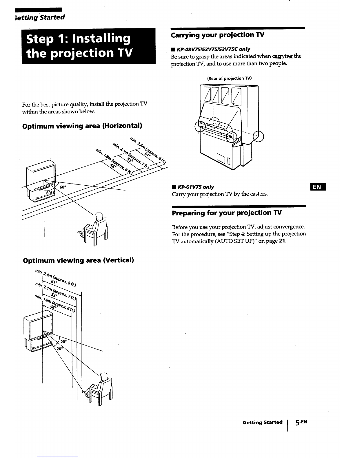
Carrying your projection TV
• KP-48V75/53V75/53V75C only
Be sure to grasp the areas indicated when caliI3ril_g the
projection TV, and to use more than two people.
(Rear of projection TV)
For the best picture quality, install the projection TV
within the areas shown below.
Optimum viewing area (Horizontal)
%
• KP-61_5 only
Carry your projection TV by the casters.
Preparing for your projection TV
Before you use your projection TV, adjust convergence.
For the procedure, see "Step 4: Setting up the projection
TV automatically (AUTO SET UP)" on page 21.
Optimum viewing area (Vertical)
Getting Started I 5"EN

Although you can use either an indoor or outdoor
antenna with your projection TV, we recommend that
you connect an outdoor antenna or a cable TV system
to get better picture quality.
Connecting an antenna
i
Connect your antenna cable to the VHF/UHF antenna
terminal. If you cannot connect your antenna cable
directly to the terminal, follow one of the instructions
below depending on your cable type.
A
• VHF only
or
• VHF/UHF
or
• Cable
75-ohm coaxial cable
(Rear of projection TV)
VHF/UHF
B
(Rear of projection TV)
• VHF only 300-ohm twin lead cable VHF/UHF
or [ '__
• UHF only
or
• VHF/UHF Antenna connector
C
75-ohm coaxial cable
• VHF
_, (Rear of projection TV)
and __F
EAC-66 U/V mixer
_j_ (not supplied)
• UHF
300-ohm twin lead cable
Notes
• Most VHF/UHF combination antennas have a signal splitter.
Remove the splitter before attaching the appropriate connector.
•" If you use the U/V mixer, snow and noise may appear in the
picture when viewing cable TV channels over 37.
Connecting an antenna/cable TV
system without a VCR
To cable or antenna
Cable
(Rear of p_je_on TV)
VHF/UHF
To cable box
If your cable company requires you to connect a cable
box, make the connection as follows:
(Rear of projection TV)
VHF/UHF
Cable _ i_ _ml_
IN I OUT
Cable box
To cable box and cable
Cable box
CATV cable
(Rear of projection TV)
AUX
TO
CONVERTER
75-ohm coaxial
cable (not supplied)
VHF/UHF
Pay cable TV systems use scrambled or encoded signals
requiring a cable box* in addition to the normal cable
connection.
* The cable box will be supplied by the cable company.
Note
- You cannot watch the signal through an AUX connector as a
window picture.
To cable and antenna
CATV cable
(Rear of projection TV)
AUX
TO
CONVERTER
Antenna cable
VHFIUHF
Note
• Do not connect anything to the TO CONVERTER connector in
this case.
6-EN Getting Started

Connecting an antenna/cable TV system with a VCR
For details on connection, see your VCR instruction
manual.
Before making the connection, disconnect the AC
power cords of the equipment to be connected.
To a conventional VCR
Note
• To connect a monaural VCR, connect the audio output of the
VCR to AUDIO-L (MONO) of VIDEO 1/3 IN on the projection
TV.
After making these connections, you will be able to do
the following:
• View the playback of video tapes
• Record one TV program while viewing another
program
• Watch two TV programs at once using PIP
Without a cable box
IN OUT
VIDE01 VIDEO 3 "rv |ONITOR AUDIO
i
(W,_,'FL_)
_o®@
AUDIO
®
"VIDEO (yellow) _
AUDIO-L (white)
AUDIO-R (red) --_
/
Rearof projection "IV
TO
%-I
I
VMC-810S/820S
(not supplied)
1
Antenna cable
_ VHFIUHF
VCR output
AUDIO VIDEO OUT_ I
LINE[_OUT IN _) Antenna cable
1 l • VHFIUHF
input
Video and audio
outputs
With a cable box
I IN
VIDEO 1 I V1DE0 3
I
I
AUDIO
I
R--
VIDEO (yellow)
AUDIO-L (white)
AUDIO-R (red)
Rearof projection "IV
OUT
/
AUDIO
AUX
@
CO_Em'EF
@
VHF/UHF
VHF/UHF
Antenna cable
VCR -
AUDIO VIDEO OUT["_-_
-
VMC-810SI820S outputs
(not supplied) "_ _ VHF/UHF
Cable box output
I _E_:_l__ll_ nbtlenna
,v, -.-I Splitter (not supplied)
Getting Started I 7 "EN
I

To an s video equipped VCR
If your VCR has an S VIDEO output connector, make
the following connections.
Whenever you connect the cable to the S VIDEO input
connector, the projection TV automatically receives S
video signals.
Without a cable box
S VIDEO'
VIDEO'
L
AUDIO
I
R--
Rear of projection W
IN OUT
_DEOI, WOEOS "rv uK_n'_ ! AUtO
I
VAl_qx]
@
m
, AUX
®
TO
@
VHFAJHF
VHF/UHF
S VIDEO
YC-15V/30V
(not supplied)
L
I
RK-74A
(not supplied)
Antenna cable
S video output _. VHF/UHF
II VCR ]_ output
uoovo ooL ....
LINE _D,, _- _ m Antenna caole
VHF/UHF
Audio input
outputs
With a cable box
Rear of projection "IV
IN OUT
_ozo 1 vmoEo3 _ M_t_n AUO_O
CVA_JFI.X: aux
_o ®
AUDIO-R (red)
S VIDEO
YC- 15W30V
(not supplied)
[
VHF/UHF
I_1_, Antenna cable
|
S video output
• LINE(Fi_
OUT_ @
VCR
OUT_-_
I
RK-74A
(not supplied)
Audio
outputs
• Note
• Video signals are composed of Y (luminance) and C (chroma)
signals. The S connection sends the two signals separately
iSreventing degradation, and gives better picture quality
compared to conventional connections.
8 "EN I Getting Started
I
Antenl
/ L_ r{---] cable
-- I Splitter
(not supplied)
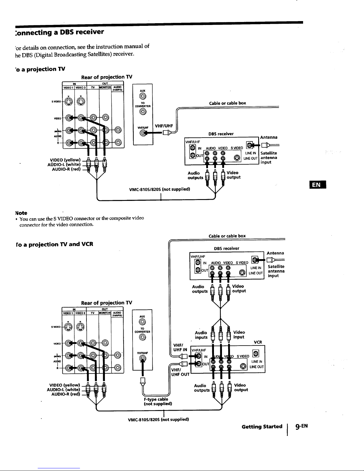
:onnecting a DBS receiver
_ordetails on connection, see the instruction manual of
he DBS (Digital Broadcasting Satellites) receiver.
,o a projection TV
IN
VIDEO 1 VIDEO 3 TY
Rear of projection TV
o_
MONITOF AUmO
(v_x)
-o6®
VIDEO (yellow) ,_,
AODIO-L (white) _
AUDIO-R (red)
/
AUX
@
TO
CONVERTER
@
VHFPJHF
Cable or cable box
VHFAJHF
IN
DBS receiver
[___Antenna
AUDIO VIDEO S VIDEO i
e O O UN-_EIN[Satellite
LINEOUT_ antenna
Jinput
Audio
outputs
r:_l 7
VMC-810S/820S (not supplied)
1
Video
Ioutput
_lote
• You can use the S VIDEO connector or the composite video
connector for the video connection.
ro a projection TV and VCR
Rear of projection TV
I IN OUT
i _9tE01 V1DE03 "i_ )1_ AUDIO
l
c0_r
X
RTER
INF
Cable or cable box
VHFAJHF
IN
Audio
outputs
DBS receiver
AUDIO VIDEO S VIDEO [_
_ LINEIN I Satellite
UNE OUT _ antenna
| input
_ Video
output
Audio
inputs
Video
input
VCR
S VIDEO [_
LINE IN
LINE OUT
VIDEO (yellow)
AUDIO-L (white)
AUDIO-R (red)
F-type cable
(not supplied)
Audio
outputs
i
VMC-810S/820S (not supplied)
Video
output
Getting Started I
9-EN
I I
Connecting a camcorder
Use this connection to view a camcorder picture.
Front of projection TV
VIDEO -_
(yellow) _
Video and
audio outputs VMC-810S/820S
(not supplied)
AUDIO-R (red)
AUDIO-L (white)
Notes
• To connect a monaural camcorder, connect the audio output of
the camcorder to AUDIO-L (MONO) of VIDEO 2 INPUT on
the projection TV.
• To connect a camcorder equipped with the S video output,
connect the S video output of the camcorder to the S VIDEO
connector of the projection TV.
Connecting an audio system
When connecting audio equipment, see page 32 for
more information.
$ InDEO
VIOEO
Au_
t
R--
Rear ofprojection TV
IN
VlOEO 1 VIDEO 3
I
I
!
i
Note
• You can adjust the bass, treble, and balance, or select surround
(page 33) or an MTS (Multichannel TV Sound) mode (page 34)
with the supplied remote control.
AUDIO OUT-L
(VAR/FIX) (white)
RK-74A (not supplied)
AUDIO OUT-R
(VAR/FIX) (red)
input
Stereo amplifier
Set the amplifier's
function to line input.
-r
10-EN Getting Started

Connecting an AV receiver
Connect an optional AV receiver to the VIDEO 1 IN
jacks at the rear of the projection TV.
If your AV receiver has the TV input jacks, connect
them to the TV OUT jacks at the rear of the projection
TV.
AUDIO-R (red)
AUDIO-L (white)
VIDEO (yellow)
I
VMC-810S/820S
(not supplied)
S YIOEO,
1
Rear of
projection TV _0Eo
n
VII )1 _.0 "IV
_2
,__ -_
q
AUE_
-Q
___ IDEO (yellow)
AUDIO-L (white)
AUDIO-R (red)
F
I
VMC-810SI820S
(not supplied)
Monitor video 1_ Monitor audio
output _J output
AV receiver
I_,_,,!, l
.....,-,-,-,-,-,
TV audio input _ "IV video input
Getting Started I 11-EN
I I
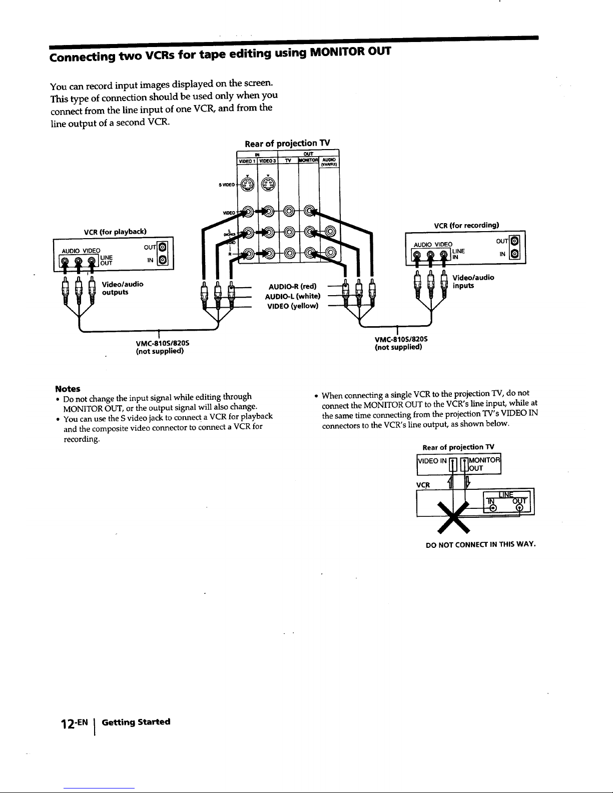
Connecting two VCRs for tape editing using MONITOR OUT
You can record input images displayed on the screen.
This type of connection should be used only when you
connect from the line input of one VCR, and from the
line output of a second VCR.
Rear of projection TV
OUT
VIDE01 V1DE03 TV WOt_OR AUDIO
VCR (for playback)
AUDIO VIDEO
____m FR,_JLINE
OUT IN
m
I I Videolaudio
outputs
I
VMC-810S/820S
(not supplied)
I i ]! ,o oViOEO ooT
AUDIO-R(red) _ _ _ _ Vnipdu_/audi°
AUDIO-L (white) -_
VIDEO (yellow) --__
i
VMC-810S/820S
(not supplied)
Notes
• Do not change the input signal while editing through
MONITOR OUT, or the output signal will also change.
• You can use the S video jack to connect a VCR for playback
and the composite video connector to connect a VCR for
recording.
• When connecting a single VCR to the projection TV, do not
connect the MONITOR OUT to the VCR's line input, while at
the same time connecting from the projection TV's VIDEO IN
connectors to the VCR's line output, as shown below.
Rear of projection TV
DO NOT CONNECT IN THIS WAY.
12"EN I Getting Started
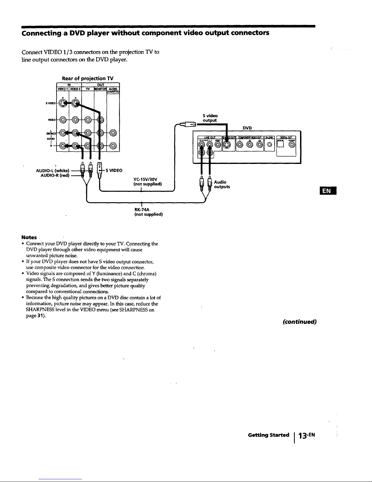
connecting a DVD player without component video output connectors
Connect VIDEO 1/3 connectors on the projection TV to
line output connectors on the DVD player.
r'
Rear of projection TV
IN OUT
vg)E01 _n0Eo3 TV _ AUDIO
;VAI_lX_
-@
AUDIO-L (white) S VIDEO
AUDIO-R (red)
YC-15VI30V
(not supplied)
1
1
RK-74A
(not supplied)
Svideo
output
i UNEOUT .SLOV.III DDV(_p_B_WEOOuTIISUNK! I O_0Ur
_1 Audio
outputs
Notes
• Connect your DVD player directly to your TV. Connecting the
DVD player through other video equipment will cause
unwanted picture noise.
• If your DVD player does not have S video output connector,
use composite video connector for the video connection.
• Video signals are composed of Y (luminance) and C (chroma)
signals. The S connection sends the two signals separately
preventing degradation, and gives better picture quality
compared to conventional connections.
• Because the high quality pictures on a DVD disc contain a lot of
information, picture noise may appear. In this case, reduce the
SHARPNESS level in the VIDEO menu (see SHARPNESS on
page 31).
(continued)
Getting Started I 13"EN

Connecting a DVD player with component video output connectors
Component video terminals Y/CB/CR provide a
sharper, higher resolution picture by reducing the
amount of signal processing thus creating a more
accurate reproduction of the source.
If your DVD player has component video output
connectors, connect them to VIDEO 4 IN on the
projection TV in the following way.
Rear of projection TV
c. (red) _
CB (blue)
Y (green) _l_ _0'
.y
L
k
AUDIO-R (red)
AUDIO-L (white)
VMC-10HG
(not supplied)
ill
' I
RK-74A
(not supplied)
Component video
outputs
LINEOUT IlSVOEDOUTII _ g_EO( II S4JNK I [1GT#LOUT
DVD
_ Audio
outputs
Notes
• Connect your DVD player directly to your TV. Connecting the
DVD player through other video equipment will cause
unwanted picture noise.
• When the DVD player is connected using VIDEO 4 IN, its
MONITOR OUT signals cannot be output.
• Some DVD player connectors may be labeled Y, B-Y, and R-Y.
In this case, connect Y (green) on the projection TV to Y on the
DVD player, CB(blue) to B-Y, and CR (red) to R-Y.
• The jacks of this projection TV are colored in green (Y), blue
(CB),and red (CR).If line output connectors of your DVD player
kave different colors, make connections according to their
labels.
• Because the high quality pictures on a DVD disc contain a lot oi
information, picture noise may appear. In this case, reduce the
SHARPNESS level in the VIDEO menu (see SHARPNESS on
__p.age31).
• If the incorrect colors appear when using this component video
input, recheck the connections they may be reversed.
14"EN I Getting Started
I I I
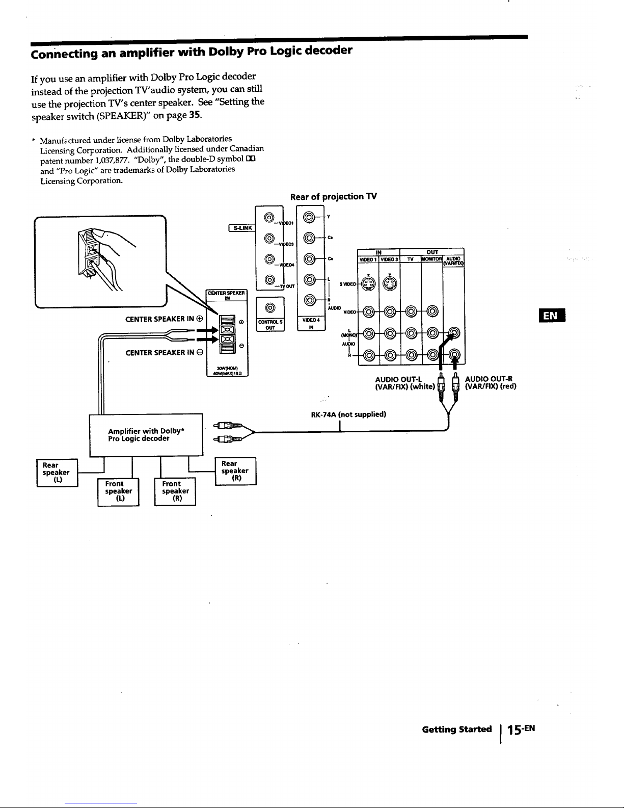
connecting an amplifier with Dolby Pro Logic decoder
If you use an amplifier with Dolby Pro Logic decoder
instead of the projection TV'audio system, you can still
use the projection TV's center speaker. See "Setting the
speaker switch (SPEAKER)" on page 35.
* Manufactured under license from Dolby Laboratories
Licensing Corporation. Additionally licensed under Canadian
patent number 1,037,877. "Dolby", the double-D symbol [][3
and "Pro Logic" are trademarks of Dolby Laboratories
Licensing Corporation.
CENTER SPEKER
m
CENTER SPEAKER IN (_
CENTER SPEAKER IN
I
I ear I I I
speaker _ I
(L) I i_;On_erl
I (" I
Amplifier with Dolby* I" _
Pro Logic decoder
I I I Rear I
speaker I
I Front I [ (R) I
I speaker I
I (R) I
Rear of
O___o,
projection "IV
:Q--.,
_)--._.
IN OUT
{_. c.,, VI_EOI WDEO$ W _mNn'o_
Q--,,,
@@_@@
VI_ 4
-_-@-@--O @-
A_O
AUI_X3
AUDIOOUT-LwAR/FIX)(white) _!
!
RK-74A (not supplied)
1
AUDIO OUT-R
(VAR/FIX) (red)
Getting Started I 15"EN
 Loading...