

Sony KP-61V35, KP-53V35, KP-46V35 Owner’s Manual
S ON&"_
3-856-609-11 (1)
Color Rear Video
Projector
Operating Instructions_
Manual de instrucciones_
I:1_1
KP-46V35
KP-53 V35
KP-61V35
© 1996 by Sony Corporation
Note on Closed Caption (Caption Vision)
This television receiver provides display of television clo>ed
captioning in accordance with §15.119 of the FCC rules.
Note on CATV system installer
This reminder is provided to call the CATV system installer',,,
attention to Article 820-40 of the NEC that provides
guidelines for proper grounding and, m particular, specifies
that the cable ground shall be connected to the grounding
system of the building, as close to the point of cable entry as
practical.
To prevent fire or shock hazard, do not
expose the unit to rain or moisture.
[l tljl [o l
RIb)x Wk ELLG I HIC bHOCK
DO NOT OPEN
LAUIILJN ILJIILDUoI lilt tll__Ku_ LLLL, JHIL_b_(JOI_
DO NOT REMOVE COVER {OR BACK)
NO USER-SERVICEABLE PARTS INSIDE
REFER SERVICING TO QUALiFiED SERVICE PERSONNEL
I hl_ >) nJbol l> intended to akq t the_ u>c_ t,, the
presence of umnsulated "dangerous voltage"
within the product's enclosure that may be of
sufficient magmtude to constitute a risk of
electric shock to persons.
ThB symbol is intended to alert the user to the
presence of important operating and
maintenance (servicing) instructions in the
literature accompanying the appliance.
CAUTION
TO PREVENT ELECTRIC SHOCK, DO NOT USE THIS
POLARIZED AC PLUG WITH AN EXTENSION CORD,
RECEPTACLE OR OTHER OUTLET UNLESS THE BLADES
CAN BE FULLY INSERTED TO PREVENT BLADE
EXPOSURE.
Use of this television receiver for other than private viewing
of programs broadcast on UHF or VHF or transmitted by
cable companies for the use of the general public may require
authorization from the broadcaster, cable company and/or
program owner.
Note on convergence adjustment
Before you use your projectmn TV, make sure to adjust
convergence. For the procedure, see page 15.
NOTIFICATION
Tins equipment has been tested and found to comply with
the limits for a Class B digital device pursuant to Part 15 of
the FCC Rules. These limits are designed to provide
reasonable protection against harmful interference in a
residential installation. This equipment generates, uses, and
can radiate radio frequency energy and, if not installed and
used in accordance with the instructions, may cause harmful
interference with radio communications. Howe\,er, there is
no guarantee that interference will not occur in a particular
installation. If this equipment does cause harmful
interference to radio or television reception, which can be
determined by turning the equipment off and on, the user is
encouraged to try to correct the interference by one or more
of the following measures:
- Reorient or relocate the receiving antennas
- Increase the separation between the equipment and
receiver.
- Connect the equipment into an outlet on a circuit different
from that to which the receiver is connected.
- Consult the dealer or an experienced radio/TV technioan
for help.
You are cautioned that any changes or modifications not
expressly approved in this manual could void your
authority to operate this equipment.
CAUTION
When using TV games, computers, and similar products with
your projection TV, keep the brightness and contrast
functions at low settings. If a fixed (non-moving) pattern is
left on the screen for long periods of time at a high brightness
or contrast setting, the image can be permanently imprinted
onto the screen. These types of imprints are not covered by
your warranty because they are the result of misuse.
2-EN
This document is for the remote commander. RM-Y137
MODELS: KP-46V35/53V35/61V35.
Please keep this notice with the instruction manual.
Owner's Record
The model and serial numbm_ are located at the _ear ot the
projection TV. Record these numbers in the spaces provided
below. Refer to them whenever you call upon your Sony
dealer regarding this product.
Model No..
Serial No
4 Welcome!
4 Precautions
Getting Started
5 Step 1: Installing the projection TV
6 Step 2: Connections
14 Step 3: Setting up the remote commander
15 Step 4: Setting up the projection TV automatically
(AUTO SET UP)
Operations
20 Watching TV programs
22 Watching two programs at one time - I'IP
23 Selecting picture and sound effects (PROGRAM
PALETTE)
24 Adjusting the picture (VIDEO)
25 Adjusting the color temperature (TRINITONE)
26 Reducing picture noise (NR)
26 Adjusting sound (AUDIO)
27 Listening to surround sound (SURROUND)
28 Listening to orchestra seat effect sound - OSE
28 Selecting stereo or bilingual programs (MTS)
29 Setting the speaker switch (SPEAKER)
29 Setting subwoofer sound
30 Setting audio out (AUDIOOUT)
30 Setting daylight saving time (DAYLIGHTSAVING)
31 Setting the clock (CURRENTTIMESET)
32 Setting the timer to turn the projection TV on and
off (ON/OFF TIMER)
33 Blocking out a channel (CHANNELBLOCK)
34 Customizing the channel names (CHCAPTION)
35 Setting video labels (VIDEOLABEL)
36 Displaying Caption Vision (CAPTIONVISION)
37 Operating video equipment
39 Operating a cable box or DBS receiver
[tI
Additional Information
40 Troubleshooting
41 Specifications
42 Index
The captions in parentheses indicate menu names.
3-EN
'lhank ).ou tol }_urcha_ing ti_u buny _olor Rear Video
Projection TV. Here are some of the features you will
enjoy with your projection TV:
• AUTO SET UP feature that allows you to set up
your projection TV easily by pressing the SET UP
button
• On screen menus that let you set the picture quality,
sound, and other settings
• Picture-in-Picture that allows you to watch another
TV channel, video or cable image as a window
picture
• On/off timer that allows you to make the TV
program of your choice be displayed on the screen
for a specified duration
• Dynamic Focus circuitry that automatically focuses
the scanning electron beam for enhanced sharpness,
especially at the corners
• Universal remote commander supplied that allows
you to operate Sony and other manufacturers' video
equipment
• S-Link TM that allows you to automatically change
the projection TV's input mode, turn on the VCR,
and play a tape by just pressing the VCR's play
button. This feature is originally designed by Sony.
About this manual
The instructions in this manual are for models KP-
46V35, KP-53V35 and KP-61V35. Before you start
reading this manual, please check your model number,
located at the rear of the projection TV. Model KP-
46V35 is used for illustration purposes in this manual.
There are no differences between these models in
operation. The differences in specifications are
indicated in the text.
Instructions in this manual are based on use of the
remote commander. You can also use the controls on
the projection TV if they have the same name as those
on the remote commander.
4-EN
I his projechun 1V opel atc_ _)11 L'xtlcnlcly high \ oltagc. 1 o
prevent fire or electric shock, please follow the precautions
below.
Safety
• Operate the projection TV only on 120 V AC.
• One blade of the plug is wider than the other for safety
purposes and will fit into the power outlet only one way.
If you are unable to insert the plug fully into the outlet,
contact your dealer.
• Should any liquid or solid object fall into the cabinet,
unplug the projection TV and have it checked by
qualified personnel before operating it further.
• Unplug the projection TV from the wall outlet if you are
not going to use it for several days or more. To
disconnect the cord, pull it out by the plug. Never pull
the cord itself.
For details concerning safety precautions, see the supplied
lea flet "IMPORTANT SAFEGUARDS."
Note on cleaning
Clean the cabinet of the projection TV with a dry soft cloth.
To remove dust from the screen, wipe it gently with a soft
cloth using vertical strokes only. Stubborn stains may be
removed with a cloth slightly dampened with a solution of
mild soap and warm water. Never use strong solvents such
as thinner or benzine for cleaning.
If the picture becomes dark after using the projection TV for a
long period of time, it may be necessary to clean the inside of
the projection TV. Consult qualified service personnel.
Installing
• To prevent internal heat build-up, do not block the
ventilation openings.
• Do not install the projection TV in a hot or humid place,
or in a place subject to excessive dust or mechanical
vibration.
• Avoid operating the projection TV at temperatures below
5°C (41°F).
• If the projection TV is transported directly from a cold to
a warm location, or if the room temperature has changed
suddenly, the picture may be blurred or show poor color.
This is because moisture has condensed on the mirror or
lenses inside. If this happens, let the moisture evaporate
before using the projection TV.
• To obtain the best picture, do not expose the screen to
direct illumination or direct sunlight. It is recommended
to use spot lighting directed down from the ceiling or to
cover the windows that face the screen with opaque
drapery. It is desirable to install the projection TV in a
room where the floor and walls are not of reflecting
material. If necessary, cover them with dark carpeting or
wall paper.
Getting Started
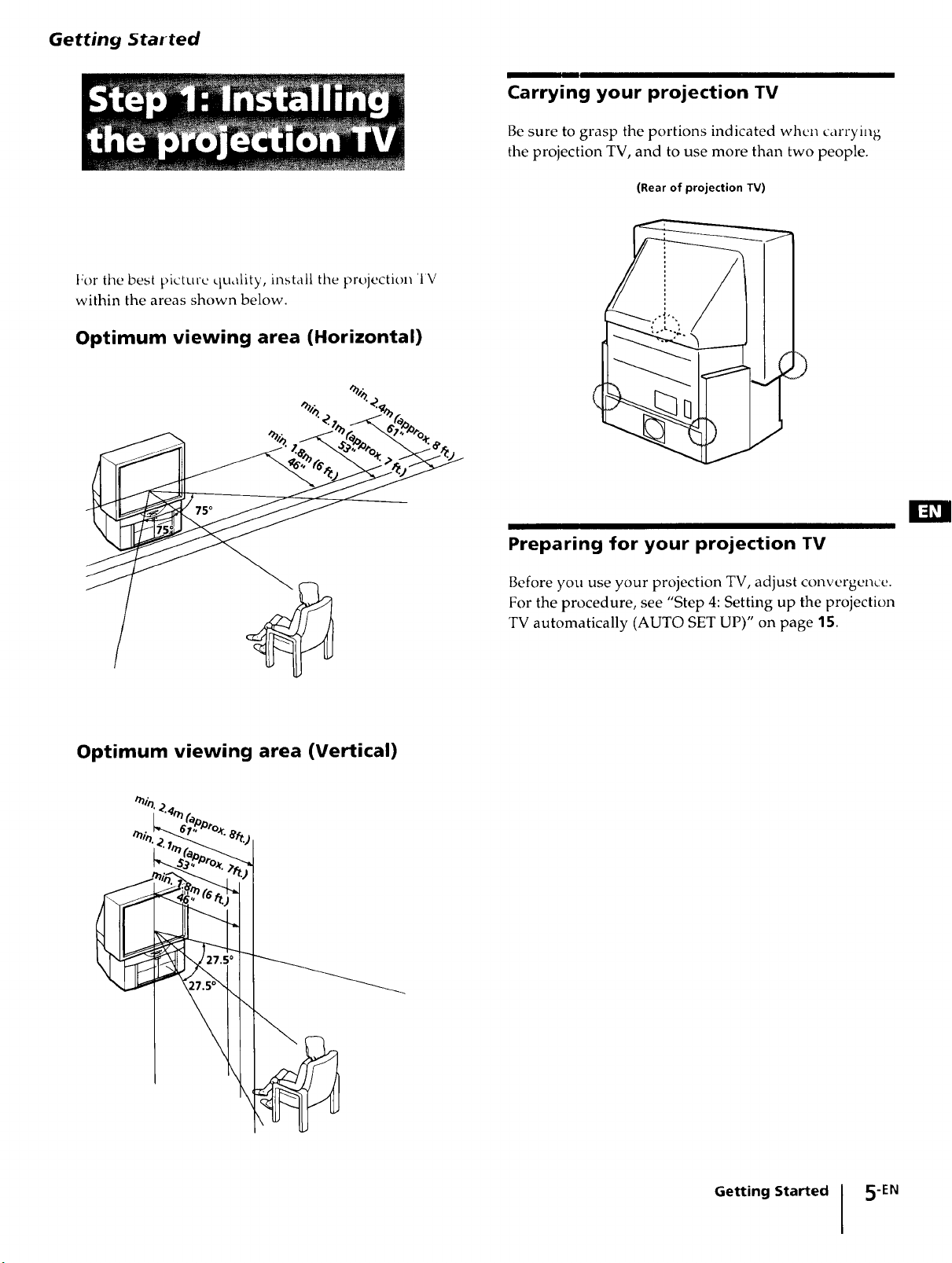
For the best pictme quality, install the projection 'IV
within the areas shown below.
Optimum viewing area (Horizontal)
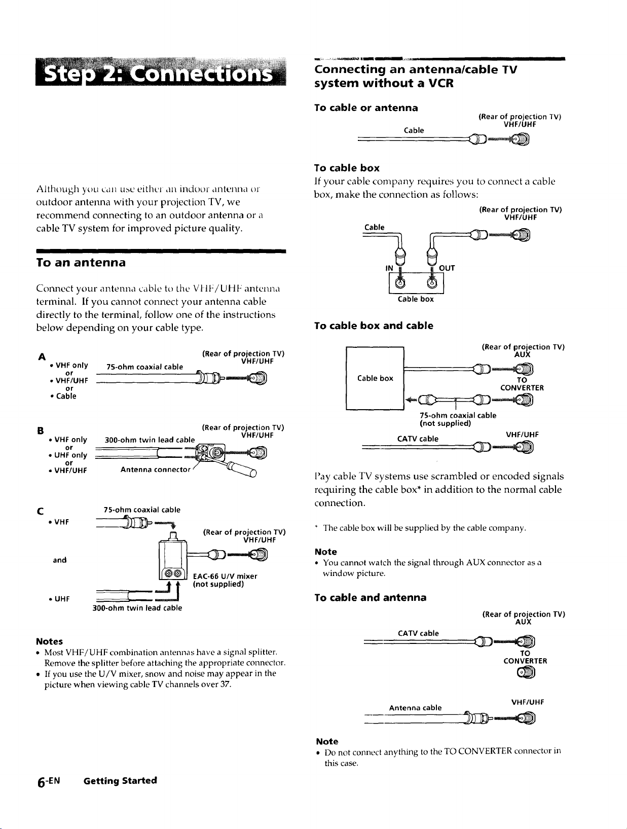
Carrying your projection TV
Be sure to grasp the portions indicated when carrying
the projection TV, and to use more than two people.
(Rear of projection TV)
Optimum viewing area (Vertical)
_.';'_o_. 7_
Preparing for your projection TV
Before you use your projection TV, adjust convergence.
For the procedure, see "Step 4: Setting up the projection
TV automatically (AUTO SET UP)" on page 15.
Getting Started 5-EN
Connecting an antenna/cable TV
system without a VCR
Although you can use either an indoor ,lntenna or
outdoor anterma with your projection TV, we
recommend connecting to an outdoor antenna or a
cable TV system for improved picture quality.
To an antenna
Connect your antenna cable to tile Vt IF/UHF antenna
terminal. If you cannot connect your antenna cable
directly to the terminal, follow one of the instructions
below depending on your cable type.
A (Rear of projection TV)
• VHF only 75-ohm coaxial cable
or
• VHF/UHF
or
• Cable
VHF/UHF
To cable or antenna
(Rear of projection TV)
Cable
VHF/UHF
To cable box
If your cable company requires you to connect a cable
box, make the connection as follows:
(Rear of projection TV)
Cable
Cable box
To cable box and cable
Cable box
VHF/UHF
(Rear of projection TV)
AUX
TO
CONVERTER
B
• VHF only
or
• UHF only
or
• VHF/UHF
C
• VHF ____
and __HF
• UHF --]_ _ (not supplied)
300-ohm twin lead cable
Antenna clnnecto_
7S-ohm coaxial cable
f-I (Rear of projection TV)
300-ohm twin lead cable
(Rear of projection TV)
EAC-66 U/V mixer
VHF/UHF
Notes
• Most VHF/UHF combination antennas have a signal splitter.
Remove the splitter before attaching the appropriate connector.
• If you use the U/V mixer, snow and noise may appear in the
picture when viewing cable TV channels over 37.
75-ohm coaxial cable
(not supplied)
CATV cable VHF/UHF
l'ay cable TV systems use scrambled or encoded signals
requiring the cable box* in addition to the normal cable
connection.
* The cable box will be supplied by the cable company.
Note
• You cannot watch the signal through AUX connector as a
window picture.
To cable and antenna
(Rear of projection TV)
CATV cable
Antenna cable
AUX
TO
CONVERTER
VHF/UHF
6-EN Getting Started
Note
• Do not connect anything to the TO CONVERTER connector in
this case.
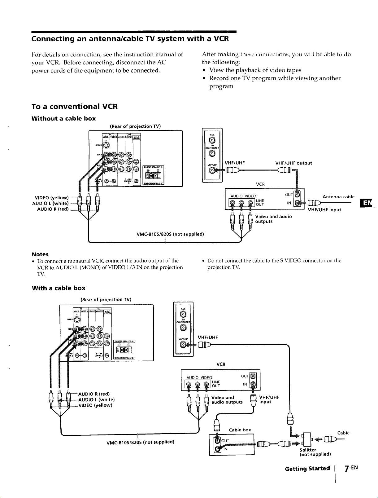
Connecting an antenna/cable TV system with a VCR
For details on connection, see the instruction manual of
your VCR. Before connecting, disconnect the AC
power cords of the equipment to be connected.
To a conventional VCR
Without a cable box
(Rear of projection TV)
I,=0,'% °°'
AUDIO L (white)
AUDIO R (red)
VMC-810S/820S (not supplied)
I
After making these connections, you will be able to do
the following:
• View the playback of video tapes
• Record one TV program while viewing another
program
Aux
@
TO
CONVERTEP
0
VHF/LIHF
VHF/UHF
VCR
AUDIO VIDEO
_u_m_
Video and audio
outputs
VHF/UHF output
Antenna cable
VHF/UHF input
Notes
• To connect a monaural VCR, connect the audio output of the
VCR to AUDIO L (MONO) of VIDEO 1/3 IN on the projection
TV.
With a cable box
(Rear of projection TV)
+_ out
$_0 _v,_os ,l_os _ITO. ¸
t_
i+++++
+__ ,+,+++
e
I
AUDIO R (red)
AUDIO L (white)
VIDEO (yellow)
VMC-810S/820S (not supplied)
i
• Do not connect the cable to the S VIDEO connector on the
projection TV.
AUX
D
TO
_ONVER_ER
0
VHF_Hr
VHF/UHF
VCR
I+0,0++ OUTer
u
Video and _ VHF/UHF
audio outputs _ input
Cable box | te
= _ _ Cab
_ I pPld'ttterp pile d )
Getting Started I 7EN
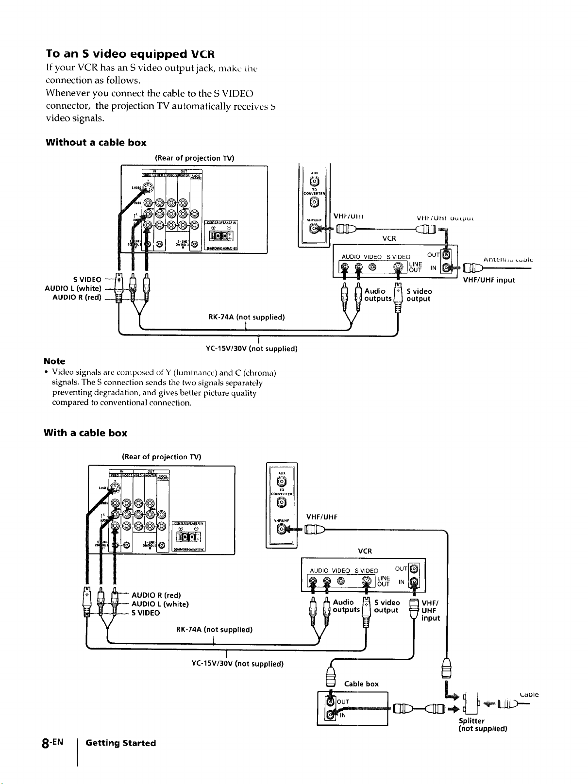
To an S video equipped VCR
Ifyour VCR has an S video output jack, make d_e
connection as follows.
Whenever you connect the cable to the S VIDEO
connector, the projection TV automatically receives b
video signals.
Without a cable box
(Rear of projection TV)
V_o_LNI_o: vt_O_ OUT
VHI-/UII/ vll|/Utn Ou Lpu_.
AUDIO L (white)
AUDIO R (red)
S VIDEO
RK-74A (not supplied)
t
t
YC-15V/30V (not supplied)
Note
• Video signals are composed of Y (luminance) and C (chroma)
signals. The S connection sends the two signals separately
preventing degradation, and gives better picture quality
compared to conventional connection.
With a cable box
(Rear of projection TV)
___
R
CONVERTeF
VHF/UHF
gg___ ,_
outputs output
_Audio _ Svideo
Aux
0
TO
D
VHF/UHF input
0
VHF/UHF
_ZD
8-EN
AUDIO R (red)
AUDIO L (white)
S VIDEO
Getting Started
RK-74A (not supplied)
I
t
YC-15V/30V (not supplied)
i
VCR
outputs output
_ Cable box
Splitter
(not supplied)
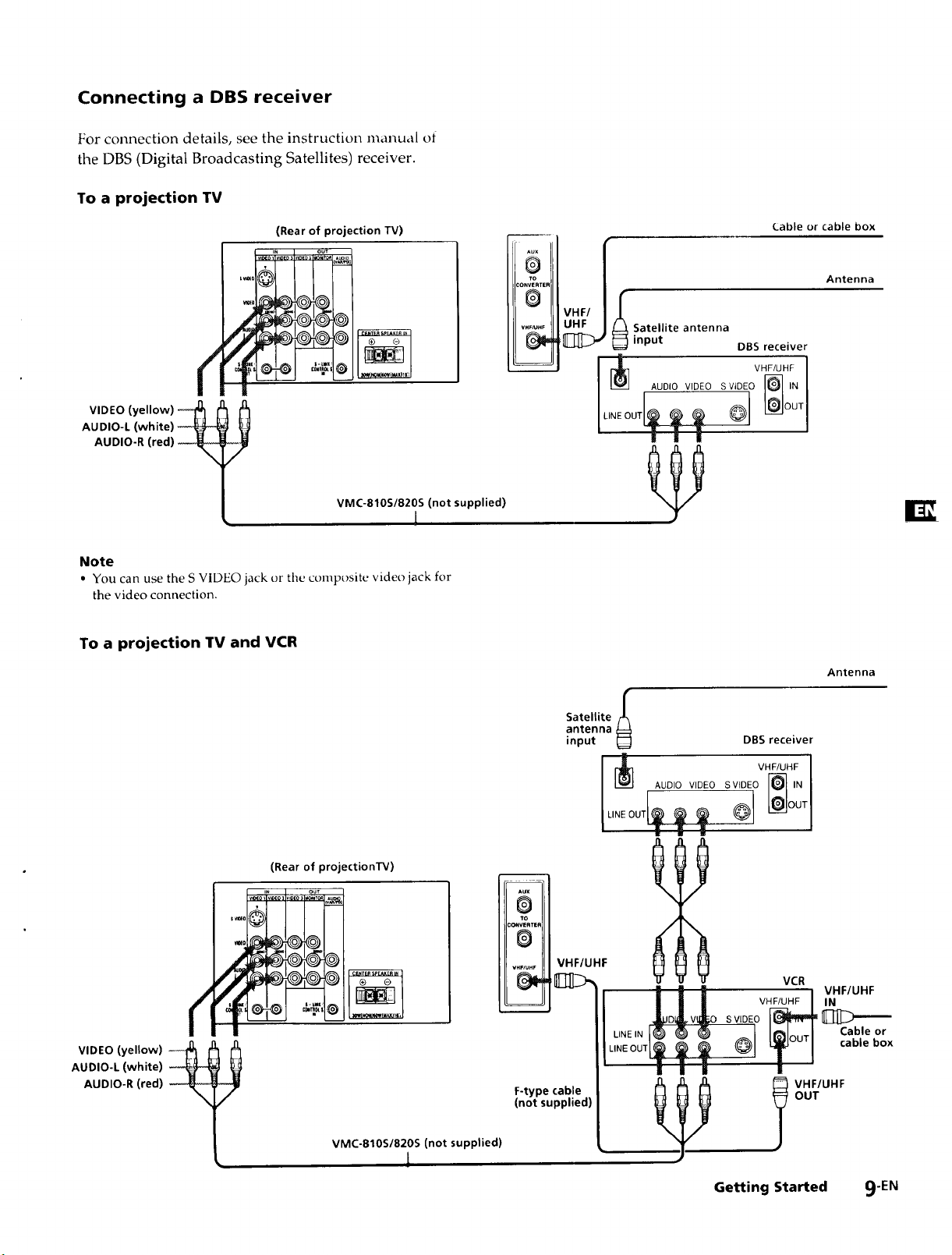
Connecting a DBS receiver
For connection details, see the instruction manual of
the DBS (Digital Broadcasting Satellites) receiver.
To a projection TV
(Rear of projection TV)
i_ o3 out
vl_o I vmEo_lVl_ =o_T0_l,_
®
_ONVERTER
WF_HF
To
@
(.able or cable box
/
Antenna
VHF/ I
Satellite antenna
input DBS receiver
VHF/UHF 1
AUDIO VIDEO SVIDEO F_ IN I
AUDIO-L (white)
AUDIO-R (red)
VIDEO (yellow)
VMC-810S/820S (not supplied)
1
Note
• You can use the S VIDEO jack or tile composite video jack for
the video connection.
To a projection TV and VCR
(Rear of projectionTV)
IN our
-0 @@
¢
AUDIO-L (white)
AUDIO-R (red)
VIDEO (yellow)
Satellite/_
antenna
input _]
m
Aux
@
TO
:ONWRrER
0
v.,,_.r VHF/UHF
F-type cable
(not supplied)
I_l°UTI
DBS receiver
VHF/UHF
AUDIO VIDEO S VIDEO
VCR
VHF/UHF
__o [_
L,N OUT T o
i I II i
Antenna
VHF/UHF
IN
._Ill>--'--
Cable or
cable box
VMC-810S/820S (not supplied)
L
Getting Started 9-EN
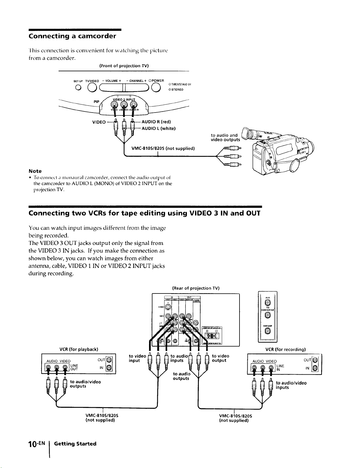
Connecting a camcorder
Ihis connection is convenient fox" watching the picture
from a camcorder.
(Front of projection IV)
SET UP TV/VIDEO - VOLUME + - CHANNEL + OPOWER
o Oc II 90 °2SS'"°°'
pl _ )
VIDEO _l _--_AUDIO R (red)-_-AUDIO L (white)
VMC-810S/820S (not supplied)
Note
• To connect a monaural camcorder, connect the audio output of
the camcorder to AUDIO L (MONO) of VIDEO 2 INPUT on the
projection TV.
to audio and
video outputs
Connecting two VCRs for tape editing using VIDEO 3 IN and OUT
You can watch input images different from the image
being recorded.
The VIDEO 3 OUT jacks output only the signal from
the VIDEO 3 IN jacks. If you make the connection as
shown below, you can watch images from either
antenna, cable, VIDEO 1 IN or VIDEO 2 INPUT jacks
during recording.
(Rear of projection TV)
m OUT
VCR (for playback)
to video
AUDIO VIDEO OUT[_]
LINE IN L_
OUT
outputs
input
_X_ _ to audio_
inputs _
to audio "
outputs
output
l o video
__/NE OUT[OIN
m
Au×
O
TO
CONVERTEF
®
VHF/UHF
0
m
VCR (for recording)
== i •
inputs
to audio/video
VMC-810S/820S
(not supplied)
10"EN I Getting Started
to audio/video
i
VMC-810S/820S
(not supplied)
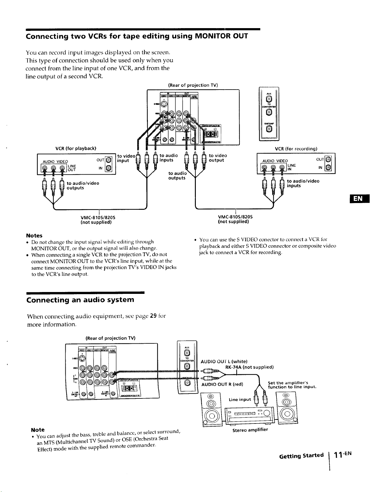
Connecting two VCRs for tape editing using MONITOR OUT
You can record input images displayed on the screen.
This type of connection should be used only when you
connect from the line input of one VCR, and from the
line output of a second VCR.
(Rear of projection IV)
I....... I=0,
Aux
O
to
:x)wve_rim
0
S
J
=
VCR (for playback)
to video h
I AUDIO VIDEO OUT_
_ o audio/video
outputs
VMC-810S/820S
(not supplied)
Notes
• Do not change the input signal while editing through
MONITOR OUT, or the output signal will also change.
• When connecting a single VCR to the projection TV, do not
connect MONITOR OUT to the VCR's line input, while at the
same time connecting from the projection TV's VIDEO IN jacks
to the VCR's line output.
input t
¢
I t° aud'° A h ht°vide° I oo,ov,o o ooq
inputs _
Connecting an audio system
0
VCR (for recording)
to audi = = =
outputs to audio/video
inputs
VMC-810S/820S
(not supplied)
• You call use the S VIDEO conector to connect a VCR for
playback and either S VIDEO connector or composite video
jack to connect a VCR for recording.
When connecting audio equipment, see page 29 for
more information.
(Rear of projection TV)
Note
• You can adjust the bass, treble and balance, or select surround,
an MTS (Multichannel TV Sound) or OSE (Orchestra Seat
Effect) mode with the supplied remote commander.
Aux
O
1to
co.ve.,E. AUDIO OU'f L (white)
_ I
y AUDIO OUT R (red) 1 Set the amplifier's
___ Afunction to line input.
RK-74A (not supplied)
Stereo amplifier
Getting Started
11-EN
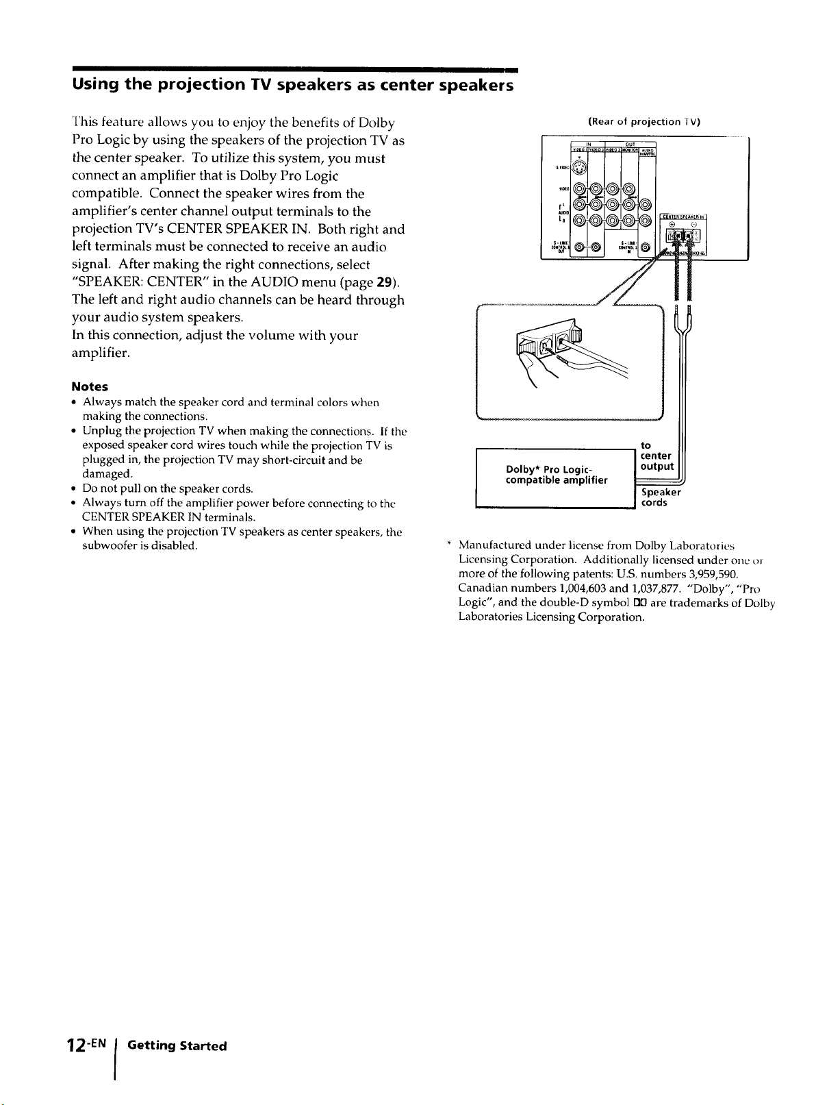
Using the projection TV speakers as center speakers
This feature allows you to enjoy the benefits of Dolby
Pro Logic by using the speakers of the projection TV as
the center speaker. To utilize this system, you must
connect an amplifier that is Dolby Pro Logic
compatible. Connect the speaker wires from the
amplifier's center channel output terminals to the
projection TV's CENTER SPEAKER IN. Both right and
left terminals must be connected to receive an audio
signal. After making the right connections, select
"SPEAKER: CENTER" in the AUDIO menu (page 29).
The left and right audio channels can be heard through
your audio system speakers.
In this connection, adjust the volume with your
amplifier.
Notes
• Always match the speaker cord and terminal colors when
making the connections.
• Unplug the projection TV when making the connections. If the
exposed speaker cord wires touch while the projection TV is
plugged in, the projection TV may short-circuit and be
damaged.
• Do not pull on the speaker cords.
• Always turn off the amplifier power before connecting to the
CENTER SPEAKER IN terminals.
• When using the projection TV speakers as center speakers, the
subwoofer is disabled.
(Rear of projection IV)
I v,xo i_,_o: Iv,_o 3 out
rL
tn
vl01(_
s-tml S-LJmll
Dolby* Pro Logic-
compatible amplifier
* Manufactured under license from Dolby Laboratories
Licensing Corporation. Additionally licensed under one oJ
more of the following patents: U.S. numbers 3,959,590.
Canadian numbers 1,004,603 and 1,037,877. "Dolby', "Pro
Logic", and the double-D symbol rid are trademarks of Dolby
Laboratories Licensing Corporation.
_lTo_
_T_OLS
I center
I Speaker
I cords
@
@
ol
to
i R-I_
12-EN Getting Started
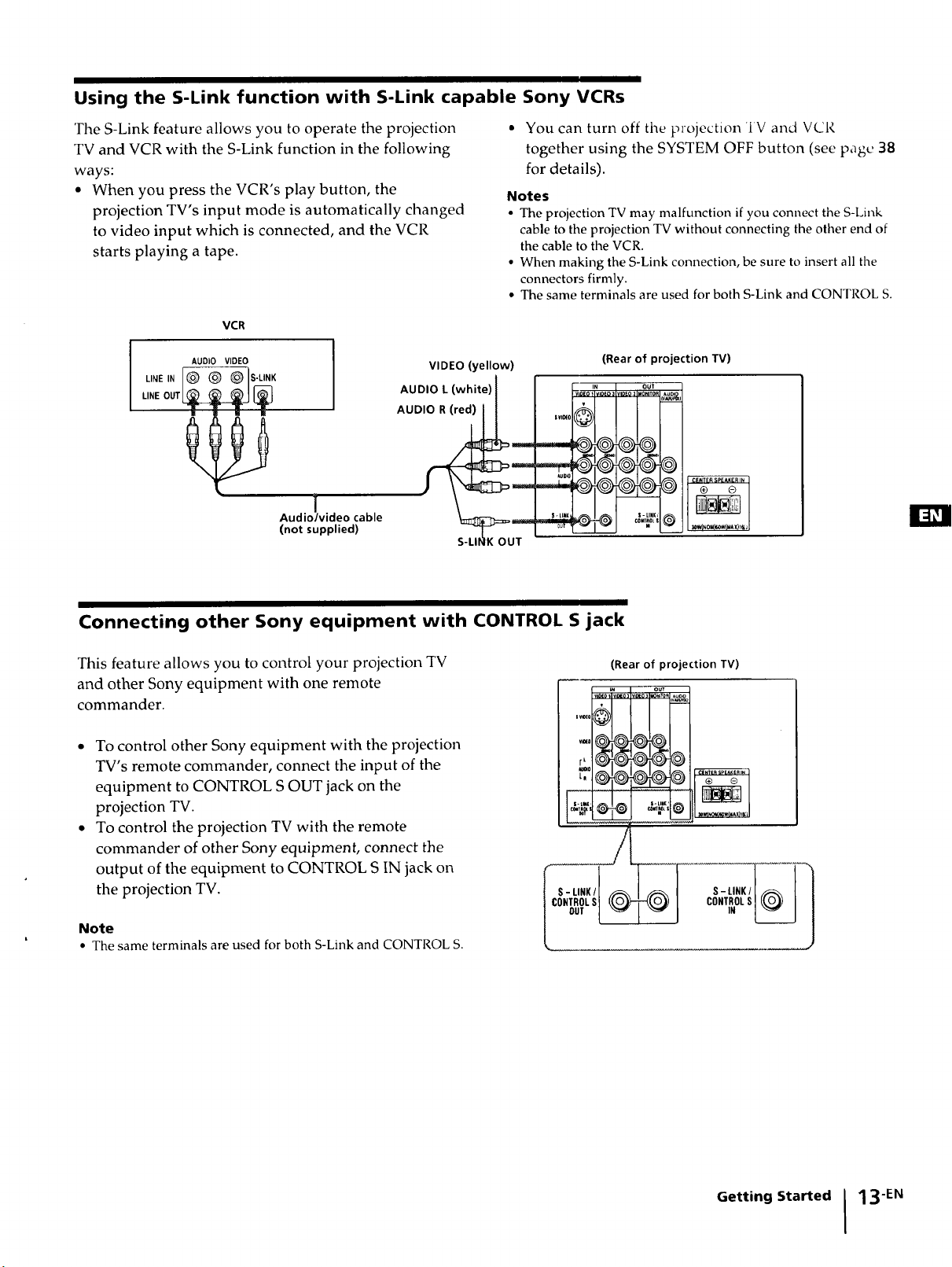
Using the S-Link function with S-Link capable Sony VCRs
The S-Link feature allows you to operate the projection
TV and VCR with the S-Link function in the following
ways:
• When you press the VCR's play button, the
projection TV's input mode is automatically changed
to video input which is connected, and the VCR
starts playing a tape.
VCR
AUDIO VIDEO
VIDEO (yellow)
_,,_,, [® ® @Is.u,,
J
Audio/video cable
(not supplied)
• You can turn off tile projection 'IV and VCR
together using the SYSTEM OFF button (see page 38
for details).
Notes
• The projection TV may malfunction if you connect the S-Link
cable to the projection TV without connecting the other end of
the cable to the VCR.
• When making the S-Link connection, be sure to insert all the
connectors firmly.
• The same terminals are used for both S-Link and CONTROL S.
(Rear of projection TV)
CENTER SP£XKER In
_WINOM_WIUAX/I_
Connecting other Sony equipment with CONTROL S jack
This feature allows you to control your projection TV
and other Sony equipment with one remote
commander.
....0
• To control other Sony equipment with the projection
TV's remote commander, connect the input of the
equipment to CONTROL S OUT jack on the
projection TV.
• To control the projection TV with the remote
commander of other Sony equipment, connect the
output of the equipment to CONTROL S IN jack on
the projection TV.
Note
• The same terminals are used for both S-Link and CONTROL S.
(Rear of projection TV)
Getting Started 13 -EN
 Loading...