

Sony KP-61V25, KP-53V25, KP-46V25 Owner’s Manual
'O:N"Y.
3-800-353.22 (2)
Engllish
Espa_ol
Color Rear Video
Projector
Operating Instructions
Manual de instrucciones
KP-46V25
Note on Closed Caption (Caption Vision)
This •television receiver provides display of television closed
captioning in accordance with §15.119 of the FCC rules.
Note on CAW system installer
This reminder is provided to call the CATV system instaUer's
attention to Article 820-40 of the NEC that provides
guidelines for proper grounding and, in particular, specifies
that the cable ground shall be connected to the grounding
system of the building, as close to the point of cable entry as
practical.
To prevent fire or shock hazard, do not
expose the unit to rain or moisture.
CAUTION: TO REDUCE THE RISK OF ELECTRIC SHOCK,
DO NOT REMOVE COVER (OR BACK).
NO USER-SERViCEABLE PARTS" INSIDE.
REFER SEI_IV CING TO QUALIRED SERVICE PERSONNEL"
This symbol js intended tO ale_ the user to the
presence of uninsulated +'dangerous voltage" "
within the product's enclosure that may be of
sufficient magnitude to constitute a risk of
electric shock to persons.
Thissymbol is intended to alert the user to the
presence of important operating and
•maintenance (servicing) instructions in the
literature accompanying the appliance.
CAUTION
TO PREVENT ELECTRIC SHOCK, DO NOT USE THIS
POLARIZED AC PLUG WITH AN EXTENSION CORD,
RECEPTACLE OR OTHER OUTLET UNLESS THE BLADES
CAN BE FULLY INSERTED TO PREVENT BLADE
EXPOSURE.
Use of this television receiver for other than private Viewing
of programs broadcast on UHF or VHF Ortransmitted by
cable companies for the use of the general• public mayrequire
authorization from the broadcaster/cable company and / or
program owner.
Note on convergence adjustment
Before you.use your projection TV, make sure to adjust
convergence. For the procedure_ see pag e 13.
NOTIFICATION
This equipment has been tested and found tO comply with
the limits for a Class B digital device pursuant.to Part 15 of
the FCC Rules. These limits are designed to provide
• reasonable protection against harmful interference in a
residential installation. .This equipment generates, Uses, and
can radiate radio frequency energy and, if notinstalled and
used in accordance with the instructions, may cause harmful -
interference with radio communications. However, there is
no guarantee that interference will not occur in a particular
installation. If this equipment does cause harmful
interference to radio or television reception, which can be
determined by turning the equipment off and on, the user is
encouraged to try to correct the interference by one or more
of the following measures: .
- Reorient'or relocate the receiving antennas
- Increase the separation between the equipment and
receiver.
- Connect the equipment into an outlet on a circuit different
from that to which the receiver is connected.
- Consult the dealer or an experienced radio/TV technician
for help.
You are cautioned that any changes or modifications not
expressly approved in this manual could void your
authority to operate this equipment.
CAUTION
When using TV games, computers, and similar products with
yDur projection TV, keep the brightness and contrast
functions at low settings. If a fixed (non-moving) pattern is
left on the screen for long periods of time at a high brightness
or contrast setting, the image can be permanently imprinted
onto the screen. These types of imprints are not covered by
your warranty because they are the result of misuse.
2-EN
This document is for the remote commander. RM-Y131
MODELS: KP-46V25 / S3V25 / 61V25.
Please keep this notice with the instruction manual.
Owner's Record
The model and serial numbers are located at the rear of the
projection TV. Record these numbers in the spaces provided
below. Refer to them whenever you call upon your Sony
dealer regarding this product.
Model No
Serial No.
4 Welcome! :
4 Precautions
Getting Started
5 Step 1: Installing the projection TV
6 Step 2: Connections
12 Step 3: Setting up the remote commander
13 Step 4: Setting up the projection TV automatically
(AUTO SET UP)
Operations
17 Watching TV programs
18 Watching two programs at one time - PIP
20 Selecting picture and sound effects (PROGRAM
PALETTE)
21 Adjusting the picture (VIDEO)
22 Adjusting the color temperature (TRINITONE)
22 Reducing picture noise (NR)
23 Adjusting sound (AUDIO)
24 Listening to surround sound (SURROUND)
24 Listening to orchestra seat effect s0und- OSE
25 Selecting stereo or bilingual programs (MTS)
25 Setting the speaker switch (SPEAKER)
26 Setting audio out (AUDIO OUT)
26 Setting daylight saving time (DAYLIGHTSAVING)
27 Setting the clock (CURRENTTIMESET)
28 Setting the timer to turn the projection TV on and
Off (ON/OFF TIMER)
29 Blocking out a channel (CHANNELBLOCK)
30 Customizing the channel number buttons (CH
CAPTION/GUIDE)
31 Setting video labels (VIDEOLABEL)
32 Displaying Caption Vision (CAPTIONVISION/XDS)
33 Operating video equipment
35 Operating a cable box
Gll
Additional Information
36 Troubleshooting
37 Specifications
38 Index
The captions in parentheses indicate menu names.
3-EN
"['hank you for purchasing the Sony• Color Rear Video
Projection TV. Here are some of the features you will
enjoy with yourprojection TV:
• AUTO SET UP feature that allows you.to.set up your
projection TV easily by pressing the SET UP button
• On screen menus that let you set the picture quality,
.sound, and other settings
o Picture-in-Pic_re that allows you to watch another TV
channel, video or.cable image as a window picture
• On/off timer that allows you to make the TV program
of your choice be.displayed on the screen for a
specified duration
• -Dynamic Focus circuitry that automatically focuses
the scanning el .ectron beam for enhanced sharpness,
especially at the comers
• Universal remote commander supplied that allows
you to operate Sony and other manufacturers' video
equipment
About this manual ..
The instructions in this manual are for models KP-
46V25, KP-53V25 and KP-61V25. Before you start '
reading this manual, please check your .model number,
located at the rear of the projection T V. Model KP-
61V25 is used for illustration purposes in this manual.
There are no differences between these models in
operation. The differences in specifications are
indicated in the text.
Instructions in this manual are based on use of the
remote commander. You can also use the controls on
the projection TV if they have the same name as those
on the remote commander.
This projection TV operates on extremely high voltag e. To
prevent fire or electric shock, please follow the precautions
below.
Safety
• For KP-46V25/53V25/61V25 operate the projection TV only
on 120 V AC, 60 Hz. For KP-53V25C operate it only on 220
V AC, 50/60 Hz. .
• One blade of the plug is wider than the other for safety
purposes and will fit into the power Outlet only oneway. If
you are unable to insert the plug fully into the outlet,
contact your dealer. "
• Should any liquid or solid object fall into the cabinet,
unplug the projection TV and have it checked by qualified
personnel before operating it further.
• Unplug the projection TVfrom the wall outlet if you are not
going to use it for several days or more. To disconnect the
cord, pull it out by the plug. Never pull the cord itself.
For details concerning safety precautions, see the supplied
leaflet"IMPORTANT SAFEGUARDS."
Note on cleaning
Clean the cabinet of the projection TV with a dry soft cloth.
To remove dust from the screen, wipe it gently With a soft.
cloth using vertical strokes only. Stubborn stains may be
removed with a cloth slightly dal_pened with a solution of
mild soap and warm water. Never use strong solvents such
as thinner or benzine for cleaning.
If the picture becomes dark after using the projection TV for a
.long period of time, it may be necessary to clean the inside of
the projection TV. Consult qu_ilified service personnel.
Installing
• To prevent internal heat build-up, do not block the
ventilation openings.
• Do not install the projection TV in a hot or humid place, or
in a place subject to excessive dust or mechanical vibration.
• Avoid operating the projection TV at temperatures below
5°C (41°F).
• If the projection TV is transported directly from a cold to a
warm location, or if the room temperature has changed
suddenly, the picture may be blurred or show poor color.
This is because moisture has condensed on the mirror or
lenses inside. If this happens, let the moisture evaporate
before using the projection TV.
• To obtain the best picture, do not expose the screen to direct
illumination or direct sunlight. It is recommended to use
spot lighting directed down from the ceiling or to cover the
windows that face the screen with opaque drapery. It is
desirable to install the projection TV in a room where the
floor and walls are not of reflecting material. If necessary,
cover them with dark carpeting or wall paper.
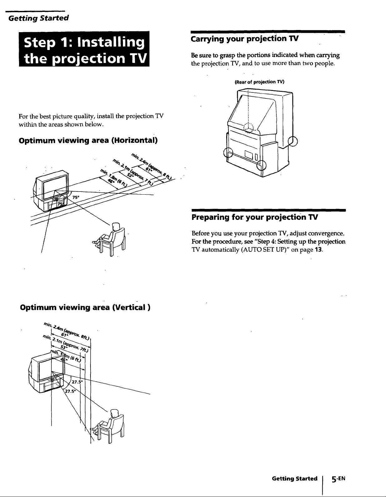
Getting Started
For the best picture quality, install the projection TV
withh_ the areas shown below.
Optimum viewing area (Horizontal)
Carrying your projection TV
Be sure to grasp the portions indicated when carrying
the projection TV, and to use more than two people.
(Rear of projection TV)
Optimum viewing area (Vertical)
",i,_._ _"_
Preparing for your projection 1_/
Before you use your projection TV, adjust convergence.
For the procedure, see "Step 4: Setting up the projection
TV automatically (AUTO SET UP)" on page 13.
Getting Started I 5"EN
i
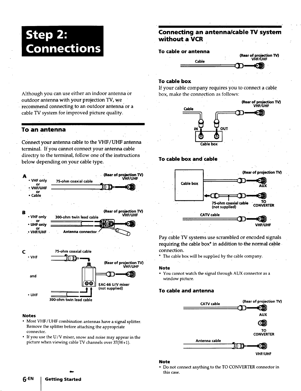
Connecting an antenna/cable TV system
without a VCR
Although you can use either an indoor antenna or
outdoor antenna with your projection TV, we
•recommend connecting to an outdoor antenna or a
cable TV system for improved picture quality.
To an antenna
Connect your antenna cable to the VHF/UHF antenna
terminal. If you cannot connect your antenna cable
directry to the terminal, follow one of the instructions
below depending on your cable type.
A
• VHF only 75-ohm coaxial cable
or
Or • .
• Cable
B
• VHF only
• or
• UHF only
• VHF/UHF •
C
• VHF
and
• UHF
or
300-ohm twin lead cable VHF/UHF
, tenOa
75-ohm coaxial cable
300-ohm twin lead cable
connector •
_EAC.66 U/v(Rearof projection TV)
"_i (not supplied)
____J
• (Rear of-projection TV)
(Rear of projection .T_
VHF/UHF
mixer
To cable or antenna
(Rear of projection TV)
Cable
VHF/UHF
-
To cable box • "
If your cable company requires you to connect a cable
box, make the connection as follows:
(Rear of projection "IV)
Cable
Cable box
VHFIUHF
To cable box and cable
I . . (Rear of projection TV)
Cable box
.75-ohm coaxial_ble • TO
(not supplied) CONVERTER
CATV cable
-
, VHFIUHF
Pay cable TV systems use scrambled or encoded signals
requiring the cable box* in addition to .the normal cable.
connection.
* The cable box will be supplied by the cable company.
Note
• You cannot watch the signal through AUX connector as a
window picture•
To cable and antenna
CATV cable
(Rear of projection TV)
Notes
• Most VHF/UHF combination antennas have a signal splitter•
Remove the splitter before attaching the appropriate
connector.
• If you use the U/V mixer, snow and noise may appear in the
picture when viewing cable TV channels over 37(W+1)•
Getting Started
6"EN ]
AUX
TO
CONVERTER
Antenna cable
VHF/UHF
Note
• Do not connect anything to the TO CONVERTER connector in
this case.

Connecting an antenna/cable TV system with a VCR
For details on connection, see the instruction manual of
your VCR. Before connecting, disconnect the AC
power cords of the equipment to be connected.
After making these connections, you will be able to do
the following:
• View the p!aybackof video tapes
• Record one TV program while viewing another
program
To a conventional vcR
Without a cable box
(Rear of projection TV)
.Q QO VHF/UHF • VHF/UHFout_
t ,00;o I
AUDIO L (white
AUDIO R (red . _ __1 Video and audio
outputs
Antenna cable
VHF/UHF input
VMC-810S/820S (not supplied)
1
Notes:
• Toconnectamonaural VCR,connect the audio output of the
VCRto AUDIO L(MONO) ofVIDEO1/3 IN on theprojection
TV.
With a cable box
(Rear of projection TV)
li iN
Q
m
0
0
@@
AUDIO L (white)
VIDEO (yellow)
_,__ UDIO R (red)
• Do notconnect thecable to theS VIDEOconnectoron the
VHF/UHF
,EID
I AUDIO VIDEO
__u_
projectionTV.
VCR
audio outputs
ouT_
input
_ VHF/UHF
VMC-810S/820S (not supplied)
I
_ Video and
Splitter
(not supplied)
Getting Started 7-EN
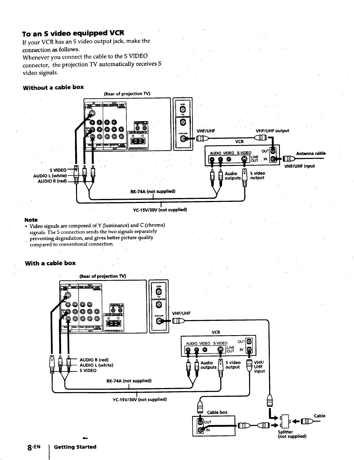
To an !; video equipped VCR
If your VCR has an S video output jack, make the
connection as follows.
Whenever you connect the cable to the SVIDEO
connector, the projection TV automatically receives S
video signals.
Without a cable box
(Rear of projection "IV)
J
Au_
O
TO
m
O
vHF/UHF
VHF/UHF output
i
AUDIO R (r_l) __-_
Note
•"Video signals arecomposed of Y(luminance) and C (chroma)
signals. The S connection sends the two signals separately
• preventing degradation,,and gives better picture quality
comparedto conventional •connection.
With a cable box
(Rear of projection TV)
il eN O_JT
_ _3 mID_menqf_
mmm
_r@@ @@
/
@@
@@
M_
m N OUT _1_
RK-74A (not supplied)
I
YC-15W30V (not supplied)
m
0
TO
€ONVlmlm
vle,_s_F
_'_ _ VCR (_ _1'_
I AU_O_O_oSWOEO_1
Antenna (able
VHF/UHF input
oo,u,
I'
.
VHF/UHF
i
VCR
AUDIO R (red)
AUDIO L (white)
S VIDEO
8-EN Getting Started
RK-74A (not supplied)
I
I
YC-15V/30V (not supplied)
AUDIO VIDEO SVIDEO
L_ LINE
Cable box
OUT IN
ts output
io :
t
I _ r{'_] Cable
iZ>-c_i3 ..,. _1____'lI>-
Splitter
(not supplied)
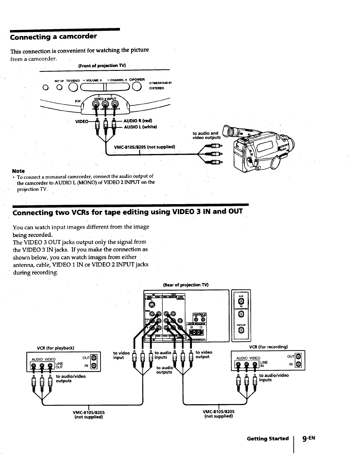
Connecting a camcorder
This connection is convenient for watching the picture
from a camcorder.
(Front of projection TV)
SETUP TV/VlDEO -VOLUME+ -CHANNEL+ OPOWER
o o Oc II _0 o:,._:o,,
_D,O--__ _--AU=OR(._
• __ AUDIO L (white). "
to audio and
video outputs
-l
Note
• Toconnect a monaural Camcorder, connect the audio Output of
the camcorderto AUDIOL 0VIONO).of VIDEO2INPUTon the
projection TV. ,,
Connecting two VCRs for tape editing using VIDEO 3 IN and OUT
You can watch input images different from the image
being recorded ....
The VIDEO 3 OUT jacks output only the signal from
the VIDEO 3 IN jacks. If youmake the connection as
shown below, you can watch image s from either
antenna, cable, VIDEO 1 IN or VIDEO 2 INPUT jacks
during recording.
(Rear of projection IV)
_m out
O
:omsmlm
AUX
O
To
O
VCR (for playback)
AUDIO VIDEO
to audio/video
outputs
VMC-810S/820S
(not supplied)
°°'N]
IN[__
!
to video
input
I _ to audio I,D
i_ua_dio_
outputs
JUi
output
to video
VMC-810S/820S
(not supplied)
O
VCR (for recording)
I _o0,ov,o_o I
l,_-_ '_"_ oo,_
inputs
to audio/video
!
Getting Started I 9"EN
iNL._
I
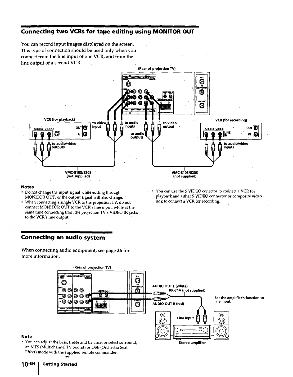
Connecting two VCRs for tape editing using MONITOR OUT
You can record input images displayed on the screen.
This type of connection should be used only when you
connect from the line input of one VCR, and from the
line output of a second VCR.
(Rear of projection TV)
OUT
=m(0
@
0
NJx
To
I
VCR(for playback)
AUDIO VIDEO " OUT
'vid-
VMC-810S/820S
(not supplied)
Notes
• Do not change the input signal while editing through
MONtTOR OUT, or the output signal will also change.
• When connecting a single VCR to the projection TV, do not
connect MONITOR OUT to the VCR's line input, while at the
same time connecting from the projection TV's VIDEO IN jacks
to the VCR's line output.
Connecting an audio system
When connecting audio equipment, see page 25 for
more information.
VCR(for recording)
AUDIO VIDEO
i
VMC-810S/820S
(not supplied)
• You can use the S VIDEO conector to connect a VCR for
•playback and either S VIDEO connector or composite video
jack to connect a VCR for record!ng.
(Rear of projection W)
L
Note
• You can adjust the bass, treble and balance, or select surround,
an MTS (Multichannel TV Sound) or OSE (Orchestra Seat
Effect) mode with the supplied remote commander.
10"EN 1 Getting Started
m
0
AUDIO OUT L(white)
0
AUDIO OUT R (red) /J_
RK-74A (not supplied)
Set the amplifier's function to
line input.
_--_ Lineinput _ __ _
I1 = .=.o
Stereo amplifier
I
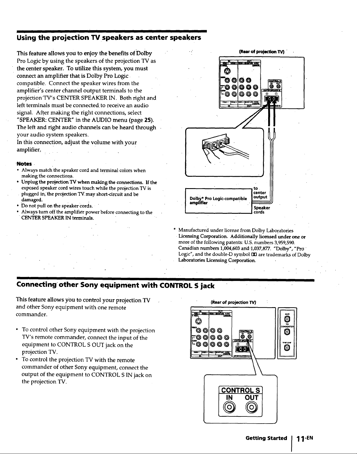
Using the projection TV speakers as center speakers
This feature allows you to enjoy the benefits of Doiby
Pro Logic by using the speakers of the projection TV as
the center speaker. To utilize this system, you must
connect an amplifier tha t is Dolby Pro Logic
compatible. Connect the speaker wires from the
amplifier's center cl_annel output terminals to the
projectionTV's CENTER SPEAKER IN. Both right and
left terminals must be connected, to receive an audio
signal. After making the right connections, select
".SPEAKER: CENTER" in the AUDIO menu (page 25).
The left and right audio channels can be heard through
your audio system speakers.
In this connection, adjust the volume with you r
amplifier,
•Notes •
• Always match the speaker cord and terminal colors when
making the connections.
• Unplug the projection TV when making.the connections. If the
exposed speaker cord wires touch while the projection TV is
• plugged in,the projection TV.may short-circuit and be
.damaged.
• Do not pull on the speaker Cords.
• Always turn off the amplifier power before connecting to the
CENTER SPEAKER IN terminals.
(Rear of projection 1V)
_NOmM_: mla3I_.n_
OUT
"oooo
*ooooo
L.@ !@@@ .
tN OUT
• tO.
Dolby* Pro Logic-compatible °l°_put[ center
amprdier " -F5_5_
I Speaker
I cords
* Manufactured under license from Dolby Laboratories
•Licensing Corporation. Additionally licensed Under one or
more of the following patents: U.S. numbers 3,959,590.
Can_idian numbers 1,004;603 an'd1,037,877. "Dolby',. "Pro "
Logic", and the double-D symbol 123 are trademarks of Dolby
Laboratories Licensing Corporation.
Connecting other Sony equipment with CONTROL S jack
This feature allows you to control your projection
and other Sony equipment with one remote
commander.
• To control other Sony equipment with the projection
TV's remote commander, connect the input of the
equipment to CONTROL S OUT jack on the
projection TV.
• To control the projection TV with the remote
commander of other Sony equipment, connect the
output of the equipment to CONTROL S IN jack on
the projection TV.
TV
IN OUT 1
"ooo
oooool
'@@@@@1
(Rear of projection "IV)
CONTROL S ]
m
_x
0
TO
0
0
Getting Started 11-EN
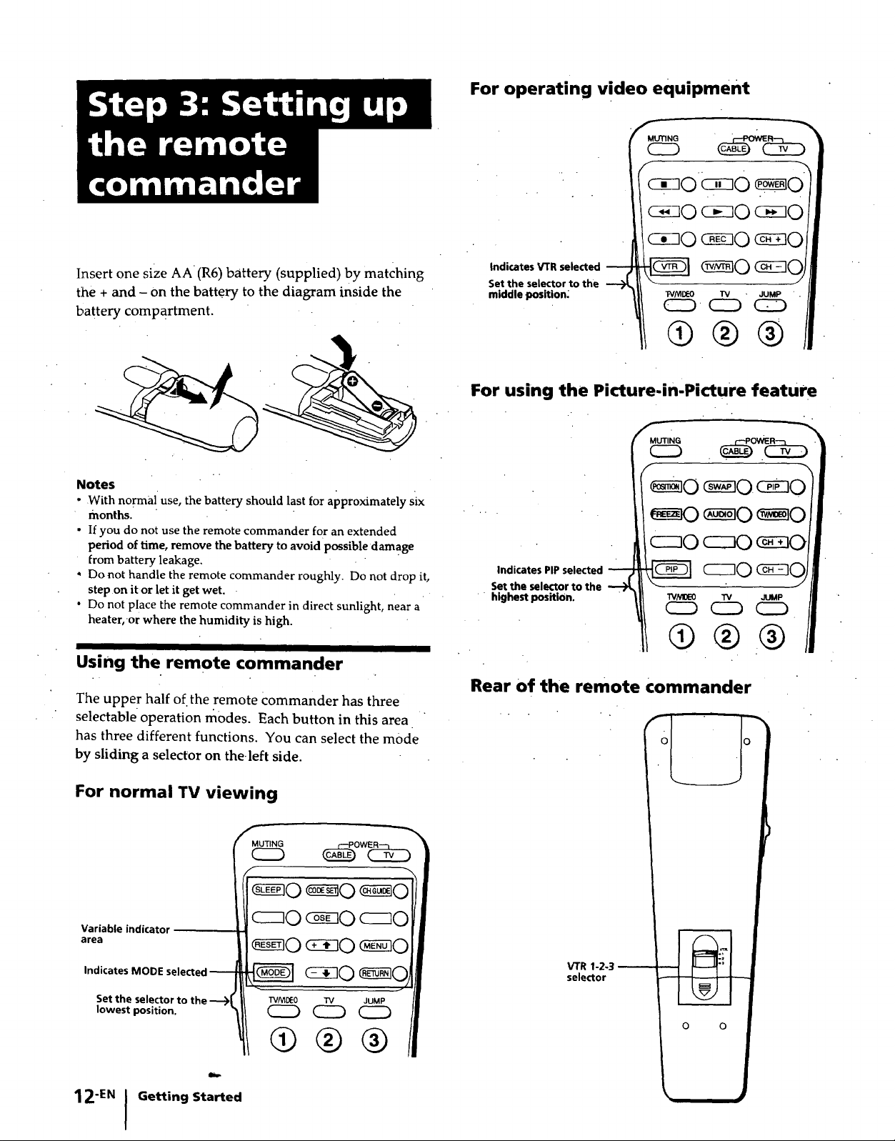
Insert one size AA (R6) battery (supplied) by matching
the + and - on the battery to the diagram inside the
battery compartment.
Notes
- Withnormal use, the batteryshould last for approximatelysix
months.
• If you do not use the remote commander for an extended
period of time, remove the batteryto avoidpossible damage
frombattery leakage.
•Donot handle the remote commander roughly• Do not drop it,
step on it or let it get wet.
', Do not place the remote commander in directsunlight, near a
heater,-or where the humidity is high.
For operating video equipment
i/_o_o_o/I
/l/_o_o_o/I
Indicates VTR selected
Set the selector to the
middle position_
11®®®/I
For using the Picture-in'Picture feature
Indicates PIP selected
Set the selector to the
" ' highest positiOn.
1_®®®11
Using the remote commander
The uppe r half of.the remote Commander has three
selectable operation modes. Each button in this area "
has three different functions. You can select the mode
by sliding a selector on the-left side.
For normal TV viewing
_0w_:_
Set the selector to the TV/_0 TV JUMP
_,,o,itoo%
Rear of the remote commander
VTR 1-2-3
selector
o o
Getting Started
 Loading...