

Sony KP 57HW40, KP 51HW40 User Manual

4-084-488-12(1)
Projection TV
© 2001 Sony Corporation
Operating Instructions
Operating Instructions
KP-51HW40
KP-57HW40
WARNING
To prevent fire or shock hazard, do not
expose the projection TV to rain or
moisture.
CAUTION
RISK OF ELECTRIC SHOCK
DO NOT OPEN
Note on Caption Vision
This television receiver provides display of television
closed captio ning in a cco rdan ce with §1 5. 119 of the F CC
rules.
Note on convergence adjustment
Before you use your projection TV, make sure to adjust
convergence. For details, see “Adjusting the Convergence
Automatically – FLASH FOCUS™ –” on page 33.
ATTENTION
RISQUE DE CHOC ELECTRIQUE,
NE PAS OUVRIR
PRECAUCION
RIESGO DE CHOQUE ELECTRICO
NO ABRIR
CAUTION : TO REDUCE THE RISK OF ELECTRIC SHOCK,
DO NOT REMOVE COVER (OR BACK).
NO USER-SERVICEABLE PARTS INSIDE.
REFER SERVICING TO QUALIFIED SERVICE PERSONNEL.
This symbol is intended to alert the user to the
presence of uninsulated “danger ous voltage”
within the product’s enclosure that may be of
sufficient magnitude to constitute a risk of
electric shock to persons.
This symbol is intended to alert the user to the
presence of impor tant operating and
maintenance (servicing) instructions in the
literature accompanying the appliance.
CAUTION
To prevent electric shock, do not use thi s polarized AC
plug with an extension cord, receptacle or other outl et
unless the blades can be fully inserted to prevent blade
exposure.
CAUTION
When using TV games, computers, and
similar products with your projection
TV, or viewing a TV station whose logo
always stays on the screen, keep the
brightness and contrast functions at
low settings. If a fixed (non-moving)
pattern such as a station logo is left on
the screen for long periods of time,
especially at a high brightness or
contrast setting, the image can be
permanently imprinted onto the screen.
These types of imprints are not cover ed
by your warranty.
Note to CATV system installer
This reminder is provided to call the CATV system
installer’s attention to Article 820-40 of the NEC that
provides guidelin es for proper grounding and, in
particular, specifies that the cable ground shall be
connected to the grounding system of the building, as
close to the point of cable entry as practical.
Use of this television receiver for other than private
viewing of programs broa dcast on UHF, VHF,
transmitted by cable companies or satellite for the use of
the general public may require authorization from the
broadcaster/cable company and/or program owner.
NOTIFICATION
This equipment has been tested and found to comply with
the limits for a Class B digital device pursuant to Part 15
of the FCC Rules. These limits are designed to provide
reasonable protection against harmful interference in a
residential installation. This equipment generates, uses,
and can radiate radio frequency energy and, if not
installed and used in accordance with the instructions,
may cause harmful interference with radio
communications. However, there is no guarantee that
interference will not occur in a particular installation. If
this equipment does cause harmful interference to radio
or television reception, which can be determined by
turning the equipment off and on, the user is encouraged
to try to correct the interference by one or more of the
following measures:
❑ Reorient or relocate the receiving antennas.
❑ Increase the separation between the equipment and
receiver .
❑ Connect the equipment into an outlet on a circuit
different from that to which the receiver is
connected.
❑ Consult the dealer or an experienced radio/TV
technician for help.
You are cautioned that any ch anges or
modifications not expressly approved in
this manual could void your warranty and
your authority to operate this equipment.
2
CAUTION
How to reduce the risk of “Image Rete ntion”
on your Projection TV
Bright, stationary images such as TV station logos
displayed on your TV can cause permanent damage to your
TV, resulting in retention of the image in the picture.
Please take the following steps to reduce the risk of causing
image retention:
View a variety of progr a m sources or programming
material.
Image retention can occur when brigh t stationary images
such as TV station logos are viewed. Changing the
program material viewed reduces the possibility that a
single image will become imprinted on the picture tubes in
your TV.
When viewing programs with stationary images, ad just the
picture setting to reduce the “Picture” and “Brightness”
levels. Image retention is accelerated by higher
“Brightness” and higher “Picture” settings.
Please refer to your instruction manual for instructions on
adjusting picture settings.
This will help you reduce the risk of causing image
retention.
IMAGE RETENTION IS NOT COVERED BY
YOUR WARRANTY
This document is for the remote control RM-Y909.
MODELS: KP-51HW40, KP-57HW40
Please keep this notice with the instruction manual.
Safety
❑ Operate the projection TV only on 120 V AC.
❑ The plug is designed, for safety purposes, to fit into
the wall outlet only one way. If you are unable to
insert the plug fully into the outlet, contact your
dealer.
❑ If any liquid or solid object should fall inside the
cabinet, unplug the projection TV immediately and
have it checked by qualified service personnel before
operating it further.
❑ If you will not be using the projection TV f or several
days, disconnect the power by pulling the plug itself.
Never pull on the cord.
For details concerning safety precautions, see
“Important Safeguards” on page 4.
Installing
❑ T o pr event internal heat b uil du p, do not blo c k the
ventilation openings.
❑ Do not install the projection TV in a hot or humid
place, or in a place subject to excessive dust or
mechanical vibration.
❑ Avoid operating the projection TV at temperature
below 5°C (41°F).
❑ If the projection TV is transported directly from a
cold to a warm location, or if the room temperature
changes sudd en l y, the p icture may be blur re d or show
poor color. In this case, please wait a few hours to let
the moisture evapo rat e befo re turnin g on the
projection TV.
❑ T o obtain the best picture, do not expose the screen to
direct illumination or direct sunligh t. It is
recommended to use spot l ighting direct ed do wn from
the ceiling or to cover the windows that face the
screen with opaque drapery. It is desirable to install
the projection TV in a room where the floor an d wa lls
are not of a reflective material.
As an ENERGY STAR® Partner,
Sony Corporation has determined
that this product meets the
ENERGY STAR
energy efficiency.
®
ENERGY STAR
TruSurround and the ( ) symbol are trademarks of SRS
Labs, Inc.
TruSurround technology is incorporated under license
from SRS Labs, Inc.
Manufactured under license from Dolby Laboratories.
Dolby and the double-D symbol are trademarks of Dolby
Laboratories.
Confidential unpubl ished works. © 1992-19 97 Dolby
Laboratories. All rights reserved.
XBR and CineMotion are trademarks of Sony.
BBE and BBE Symbol are trademarks of BBE Sound, Inc.
and are licensed by BBE Sound, Inc. under U.S. Patent No.
4,638,258 an d 4, 482,866.
is a U.S. registered mark.
®
guidelines for
ATTENTION
Pour prévenir les chocs électriques, ne pas utiliser cette
fiche polarisée avec un prolongate ur, une prise de courant
ou une autre sortie de courant, sauf si les lames peuv ent tre
inserées à fond sans en laisser aucune partie à decouvert.
Owner’s Record
The model and serial numbers are located at the rear of the
projection TV, below the Sony logo, on the sticker, and
also on the TV box (whi te lab el ) . Rec o rd th es e nu m ber s in
the spaces provided below. Refer to them whenever you
call upon your Sony dealer regarding this product.
Model No.
Serial No.
3
Important Safeguards
For your protection, please read these instructions
completely, and keep this manual for future reference.
Carefully observe and comply with all w arnings, cautions
and instructions placed on the set or described in the
operating instructions or service manual.
WARNING
To guard against injury, the following basic safety
precautions should be observed in the installation, use
and servicing of the set.
Use
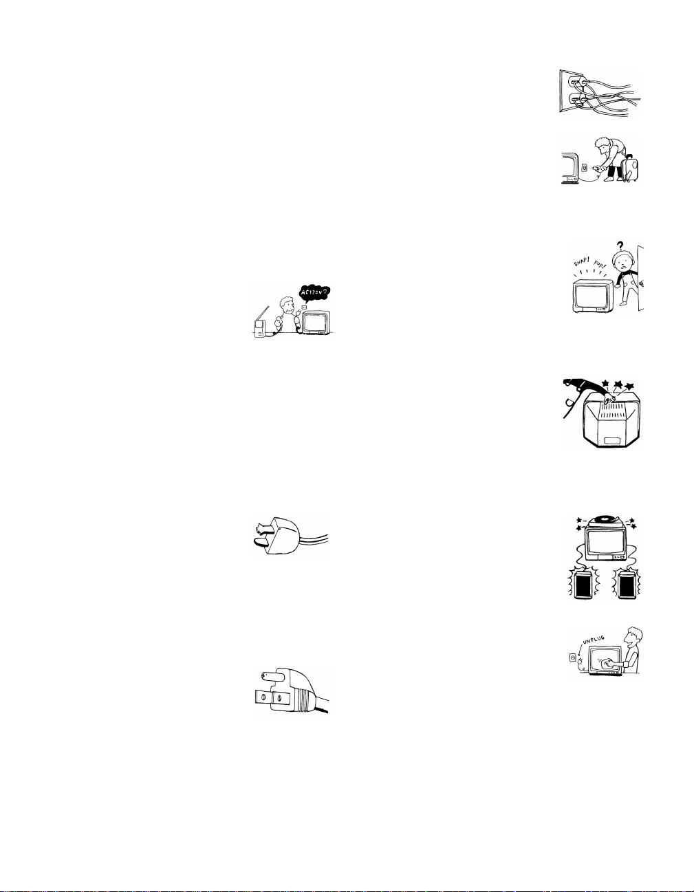
Power Sources
This set should be operated only from
the type of power source indicated on
the serial/model plate. If you are not sure
of the type of electrical power supplied
to your home, consult your dealer or
local power company. For those sets designed to operate
from battery power, refer to the operating instructions.
Grounding or P olarization
This set is equipped with a polarized AC power cord plug
(a plug having one blade wider than the other), or with a
three-wire grounding type plug (a plug having a third pin
for grounding). Follow the instructions below:
Overloading
Do not overload wall outlets, extension
cords or convenience receptacles
beyond their capacity, since this can
result in fire or e lectric shock.
Always turn the set off when it is not
being used. When the set is left
unattended and unused for long
periods of time, un plug it from the
wall outlet as a precaution against the
possibility of an internal malfunction that could create a
fire hazard.
If a snapping or popping sound from a TV
set is continuous or frequent while the TV
is operating, unplug the TV and c onsult
your dealer or service technici an. It is
normal for some TV sets to make
occasional snappin g or popping sounds,
particularly when being turned on or off.
Object and Liquid Entry
Never push objects of any kind into the
set through the cabinet slots as they may
touch dangerous voltage points or short
out parts that could result in a fire or
electric shock. Never spill liquid of any
kind on the set.
For the set with a polarized AC power cord
plug
This plug will fit into the power outlet
only one way. This is a safety feature. If
you are unable to insert the plug fully
into the outlet, try reversing the plug. If
the plug still fails to fit, contact your electric ian to ha ve a
suitable outlet installed. Do not defeat the safety purpose
of the polarized pl ug by forcing it in.
Alternate Warning for the set with a threewire grounding type AC plug
This plug will only fit into a groundingtype power outlet. This is a safety
feature. If you are unable to insert the
plug into the outlet, contact your
electrician to have a suitable outlet
installed. Do not defeat the safety purpose of the
grounding plug.
4
Attachments
Do not use attachments not
recommended by the manufacturer, as
they may cause hazards.
Cleaning
Clean the cabinet of the projection TV
with a dry soft cloth. To remove dust
from the screen, wipe it gent ly with a soft
cloth. Stubborn stains may be removed
with a cloth slightly dampened with
solution of mild soap and warm water. Never use strong
solvents such as thinner or benzine for cleaning.
If the picture becomes dark after using the projection TV
for a long period of time, it may be necessary to clean th e
inside of the projection TV. Consult qualified service
personnel.
Installation
Water and Moisture
Do not use power-line operated sets
near water — for example, near a
bathtub, washbowl, kitchen sink, or
laundry tub, in a wet basement, or
near a swimm i n g pool, etc.
Accessories
Do not place the set on an unstable
cart, stand, table or shelf. The set
may fall, causing serious injury to a
child or an adu lt and se rious dam age
to the set. Use only a cart or stand
recommended by the manufacturer
for the specific model of projection
TV. An appliance and car t
combination shoul d be moved with
care. Quick stops, excessive force,
and uneven surfaces may cause the appliance and cart
combination to overturn.
Ventilation
The slots and openings i n the cabinet and in the back or
bottom are provided for necessary ventilation. To ensure
reliable operation of the set, and to protect it from
overheating, these slots and openings must never be
blocked or covered.
❑ Never cover the slots and openings
with a cloth or other materials.
Power-Cord Protection
Do not allow anything to rest on or roll
over the power cord, and do not place the
set where the power cord is subject to
wear or abuse.
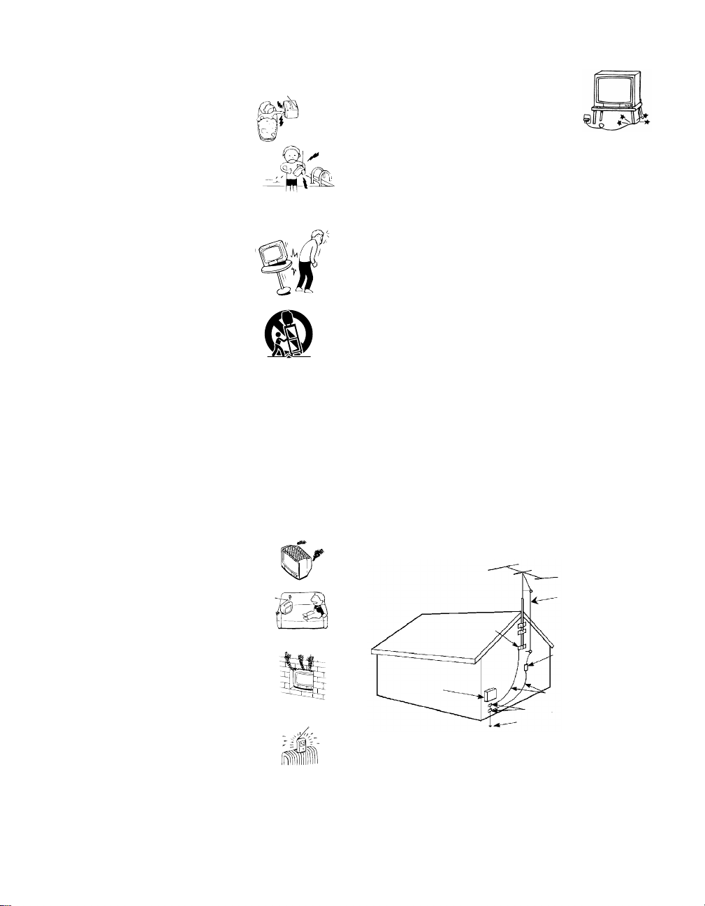
Antennas
Outdoor Antenna Grounding
If an outdoor antenna is installed, follow the precautions
below. An outdoor antenna system should not be located
in the vicinity of overhead power lines or other electric
light or power circuits, or where it can come in contact
with such power lines or circuits.
WHEN INSTALLING AN OUTDOOR ANTENNA
SYSTEM, EXTREME CARE SHOULD BE TAKEN TO
KEEP FROM CONTACTING SUCH POWER LINES
OR CIRCUITS AS CONTACT WITH THEM IS
ALMOST INVARIABLY FATAL.
Be sure the antenna system is grounded so as to provide
some protection against voltage surges and bu ilt-up sta tic
charges.
Section 810 of the National Electrical Code (NEC) in
USA and Section 54 of the Canadian Electrical Code in
Canada provides information with respect to proper
grounding of the mast and supporting structure,
grounding of the lead-in wire to an antenna discharge
unit, size of groundi ng conductors, location of antenna
discharge unit, connect ion to grounding el ectrodes, and
requirements for the grounding elect rode.
Antenna Grounding According to the NEC
Refer to section 54 -300 of Canadian Electrical Code for
Antenna Ground in g.
❑ Never block the slots and openings by
placing the set on a bed, sofa, rug or
other similar surface.
❑ Never place the set in a confined
space, such as a bookcase or built-i n
cabinet, unless proper ventilat ion is
provided.
❑ Do not place the set near or over a
radiator or heat register, or where it is
exposed to direct sunlight.
Ground clamp
Electrical
service
equipment
NEC: National
Electrical Code
Antenna lead-in wire
Antenna lead-in wire
(NEC Section 810-20)
Grounding conductors
(NEC section 810-21)
Ground clamps
Power service grounding
electrode system (NEC Art
250 Part H)
5
Lightning
For added protection for this television receiver during a
lightning storm , or when it is left unattended and unused
for long periods of time, unplug it from the wall outlet
and disconnect the antenna. This will prevent damage to
the receiver due to lightning and power-line surges.
Service
Damage Requiring Service
Unplug the set from the wall outlet and refer servicing to
qualified service personnel under the following
conditions:
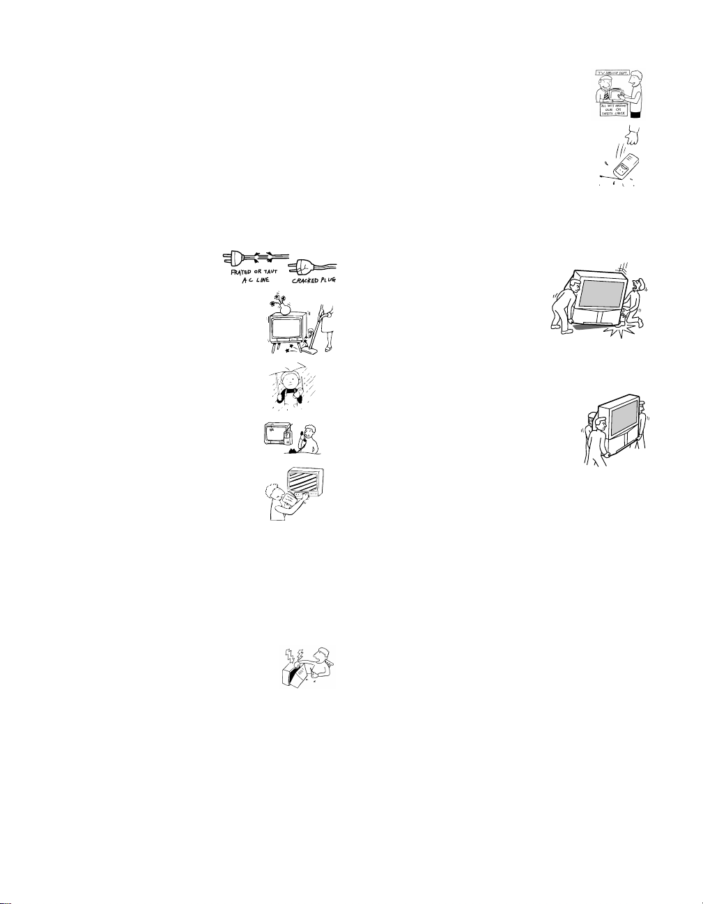
❑ When the power cord or
plug is damaged or frayed.
❑ If liquid has been spilled into
the set.
❑ If the set has been exposed
to rain or water.
❑ If the set has been subject to
excessive shock by being
dropped, or the cabinet has
been damaged.
❑ If the set does not operate
normally when following the
operating instructions.
Adjust only those controls
that are specified in the
operating instructions.
Improper adjustment of
other controls may result in
damage and will often
require extensive work by a
qualified technician to restore the set to normal
operation.
❑ When the set exhibits a distinct change in
performance, it indicates a need for servi ce.
Safety Check
Upon completion of any service or repairs
to the set, ask the service technician to
perform routine safety checks (as specified
by the manufacturer) to determine that the
set is in safe operating condition, and to so
certify. When the set reaches the end of its
useful life, improper disposal could result
in a picture tube implosion. Ask a qualified
service technician to dispose of the set.
For Safety
Be careful when moving
the projection TV
When you place the projection TV
in position, be careful not to drop it
on your foot or fingers.
Watch your footing while installing the projection TV.
Carry the projection TV in the
specified manner
If you carry the projection TV in a ma nner
other than the specified manner and
without the specifi ed number of persons, it
may drop and a serious injury may be
caused. Be sure to follow the instructions mentioned
below.
❑ Carry the projection TV with the specified number
of persons. (see page 10)
❑ Do not carry the projection TV holding the speaker
grill.
❑ Hold the projection TV tightly when carrying it.
Servicing
Do not attempt to service the set by yourself
since opening the cabinet may expose you to
dangerous voltage or other hazards. Refer all
servicing to qualified service personnel.
Replacement Parts
When replacement parts are required, be sure the service
technician certifies in writing that he has used
replacement parts specif ied by the manufactu rer that ha ve
the same characteristics as the origi nal parts.
Unauthorized substitutions may result in fire , electric
shock or other hazards.
6

Contents
Introducing the Sony Projection TV
Presenting the Sony Projection TV..........................8
Using this manual........................ ... .........................9
Installing and Connecting the
Projection TV
Contents.................................................................10
Inserting Batteries into the Remote Control..........10
Carrying Your Projection TV ................................10
Installing the Projection TV................ .... ...............11
Connector Types....................................................12
Projection TV Controls and Connectors ................13
Basic Connections (Connecting Cable TV or
Antenna).........................................................16
Connecting a VCR and Cable................................19
Connecting a VCR and Cable Box ........................20
Connecting Two VCRs for Tape Editing ..............22
Connecting a Satellite Receiver.............................23
Connecting a Satellite Receiver with a VCR.........24
Connecting an Audio Receive r...................... ........25
Connecting a DVD Player with Component
Video Connectors..........................................26
Connecting a DVD Player with A/V Connectors ..27
Connecting a Digital TV Receiver.........................28
Connecting a Camcorder .......................................29
Connecting an AV Receiver ..................................30
Using the CONTROL S Feature............................31
Setting Up the Projection TV Automatically.........32
Adjusting the Convergence Automatically
– FLASH FOCUS™ –...................................33
Using the Menus
Overview................................................................48
Using the Video Menu......................... ... .... ..........49
Using the Audio Menu.......... .... ... .........................51
Using the Channel Menu......................................53
Using the Wide Menu........................................ ...55
Using the Timer Menu................................ ..........57
Using the Setup Menu ................................ ... .......58
Other Information
Programming the Remote Control.........................68
Operating Other Components with Your Projection
TV Remote Control......................... .... ... .... ...71
Troubleshooting.....................................................73
Specifications.........................................................76
Using the Features
Using the Remote Control...................... ... .... ........34
Watching the TV....................................................37
Watching the Digital TV........................................39
Using Favorite Channels................. .......................40
Using Twin View™...............................................41
Using the Freeze Function.....................................44
Using Scrolling Channel Index..............................45
Using Wide Screen Mode....................... ... ............47
7

Introducing the Sony Projection TV
Presenting the Sony Projection TV
Thank you for purchasing the Sony Projection TV.
This manua l is for models KP-51HW40 and KP-57HW40.
Model KP-51HW40 is used for illustration purposes.
Features
Some of the features that you will enjoy with your new projection TV
include:
❑
Hi Scan 1080
digital TV formats. By using the VIDEO 5/6 IN jacks, you can connect
a DTV (digital television) receiver to view DTV programs.
❑
DRC™ Multi-Function: Unlike conventional line doublers, the DRC
feature doubles vertical and horizontal lines, resulting in four times the
density for quality sources such as DVD, Satellite and Digital
camcorder.
❑
CineMotion™: Using the 2-3 Pull-Down technology, the CineMotion
feature allows you to obtain a smooth picture movement when playing
back movies or other video sources on film.
❑
Twin View™: Using Multi-Image Driver (MID-X), Twin View allows
you to watch two programs side by side with the ability to zoom in on
one picture and listen to the program in the selected window. You can
watch pictures from two different sources (1080i, 720p, 480p or 480i)
simultaneously.
❑
Steady Sound™: Equalizes volume levels so there is consistent output
between programs and commercials.
❑
Parental Control: V-Chip technology allows parents to block
unsuitable programming for younger viewers.
❑
Component Video Inputs: Offers the best video quality for DVD
(480p, 480i) and Digital Set-top box (1080i, 720p, 480p, 480i)
connections.
❑
S-VIDEO Inputs: Provides a high-quality image for connected
equipment.
❑
Favorite Channel Preview : Preview up to eight favorite channels
without leaving the current channel.
❑
Scrolling Channel Index: Allows you to view and choose channels
from scrolling pictures without leaving the current channel.
™
: Enables you to receiv e th e 108 0i, 7 20p, 480p and 480i
8

Using this manual
Introducing the Sony Projection TV
❑
Wide Screen Mode: Allows you to watch 4:3 normal broadcasts in
wide screen mode (16:9 aspect ratio).
❑
Auto Wide: Allows you to select the wide screen mode automatically.
❑
Flash Focus
We recommend that you carefully review the contents of the following three
sections in the order shown to ensure that you fully un derst and the operat ion
of your new projection TV.
Installing and Connecting the Projection TV
1
This section guides you through your initial setup. It shows you how to
install your projection TV, to connect your new components and to connect
the antenna and cable.
Using the Features
2
This section shows you how to begin using your new projection TV. It also
shows you how to use your remote control functions.
Using the menus
3
™
: Allows you to adjust convergence automatically.
Introducing the Sony Projection TV
This section teaches you how to access on-screen menus and adjust your
projection TV settings.
Instructions in this manual are written for the remote control. Similar
controls are also found on the projection TV console.
9
Installing and Connecting the Proj ection TV
Contents
The box contains your new projection TV, a remote control and two AA
batteries. No peripheral cables are included. If you intend to add additional
equipment to your projection TV, please check the hookup instructions for
your desired setup before you begin. You may need to purchase cables and/
or splitters to complete the hookup properly.
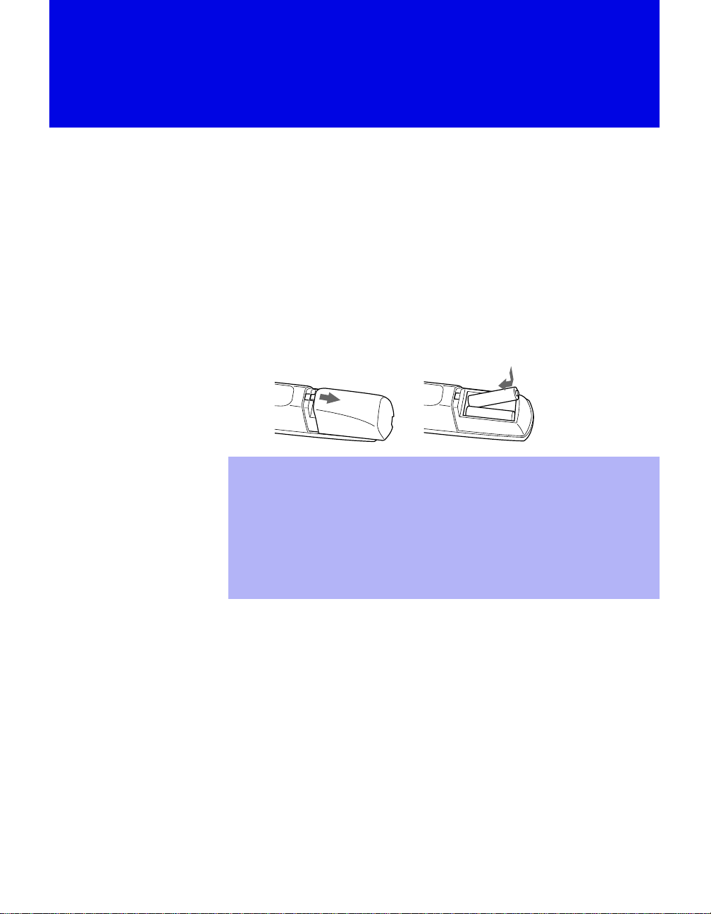
Inserting Batteries into the Remote Control
Insert two size AA (R6) batteries (supplied) by matching the + and – on the
batteries to the diagram inside the battery compartment.
e
E
e
E
Remove the batteries to avoid damage from possible battery leakage
✍
whenever you anticipate that the remote control will not be used for an
extended pe riod.
Handle the re mote control with care. Avoid dropping it, getting it wet, or
✍
placing it in direct sunlight, near a heater, or where the humidity is high.
Your remote control can be programmed to operate most video
✍
equipment. (See “Programming the Remote Control” on page 68.)
Carrying Your Projection TV
Carrying the projection TV requires three (3) or more people.
The projection TV has been equipped with casters for easy movement on a
hard surface.
Please move your projection TV using the casters.
10
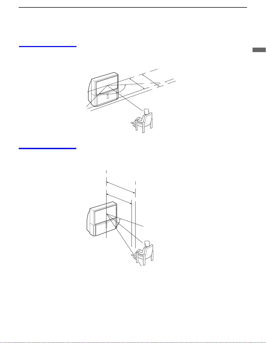
Installing the Projection TV
Installing and Connecting the Projection TV
Recommended viewing area (Horizontal)
Recommended viewing area (Vertical)
min. 2.1 m (approx. 7 ft.)
min. 1.8 m (approx. 6 ft.)
51"
60
˚
60 60
˚
min. 2.1 m (approx. 7 ft.)
57"
min. 1.8 m (approx. 6 ft.)
51"
Installing and Connecting the Projection TV
57"
20
˚
20
˚
11
Installing and Connecting the Projection TV
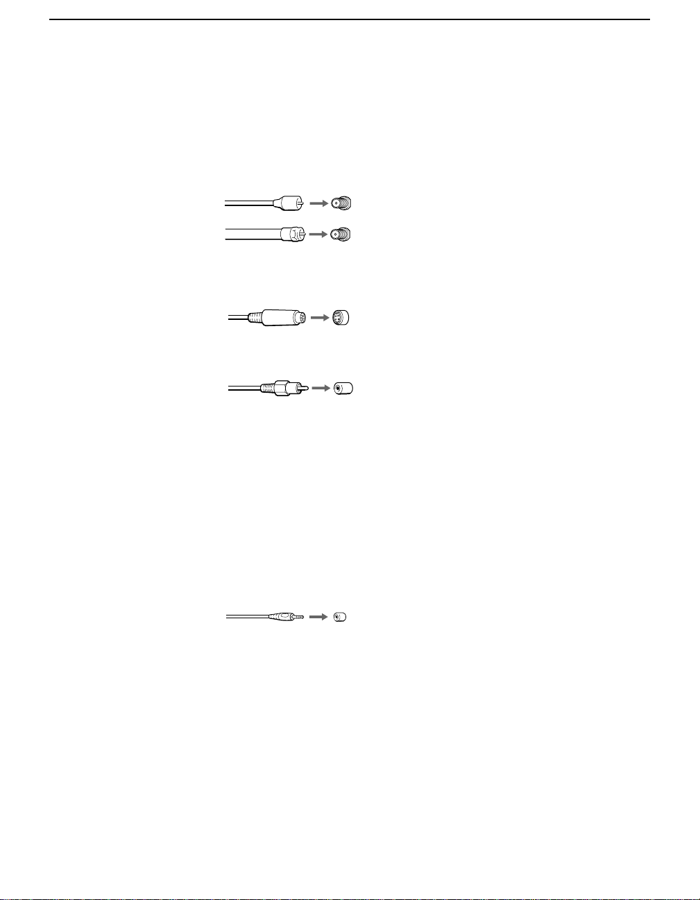
Connector Types
You may find it necessary to use some of the following connector types
during set up.
Coaxial cable
Standard TV cable and antenna cable
Plug Type
Screw-on Type
S Video cable
High quality video cable for enhanced picture quality
Audio/Video cabl e
Video - Yellow
Audio (Left) - White
Audio (Right) - Red
Push into connection.
Screw into connection.
Align guides and push
into connection.
Push into connection.
12
Some DVD Players are equipped with the following three video connectors:
Y - Green
P
(CB, Cb or B–Y) - Blue
B
P
(CR, Cr or R–Y) - Red
R
CONTROL S cable
CONTROL S connect ions are exclusive to Sony products and allow greater
control of all Sony equipment.
Push into connection.
Installing and Connecting the Projection TV
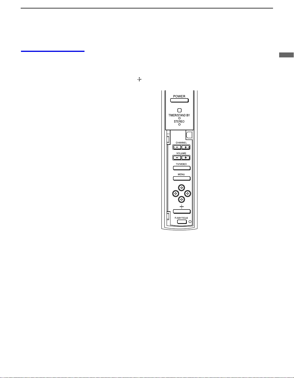
Projection TV Controls and Connectors
Front Panel Menu Controls
The front panel menu controls allow access to the on-screen menus without
the use of a remote control. Pressing MENU
The arrow buttons move the on-screen cursor in the menus and by pressing
the Select button ( ) selects the menu item.
brings up the on-screen menus.
Installing and Connecting the Projection TV
13
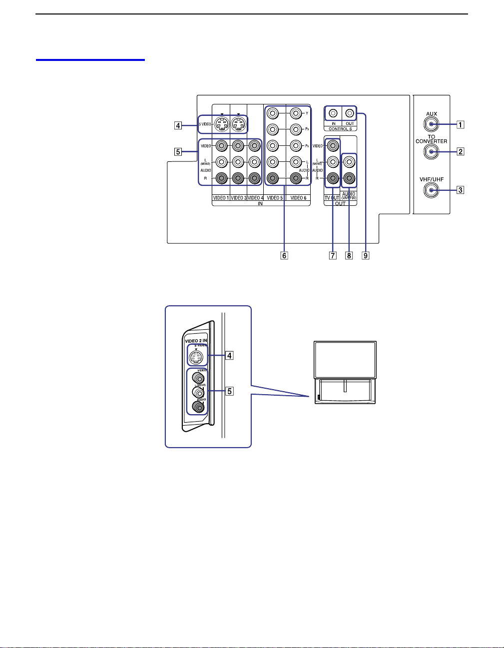
Installing and Connecting the Projection TV
Projection TV Rear
and Front Panel
Rear of projection TV
Connectors
Front of projection TV
14

Installing and Connecting the Projection TV
Connection Description
1 AUX Allows you to view local and cable channels if your cable
provider does not feature local channels. You can switch
between local and cable channels easily by pressing ANT
on the remote control. Devices connected to the AUX
input cannot be viewed in Twin View.
2 TO CONVERTER This is a VHF/UHF OUT jack that lets you set up your
projection TV to switch between scrambled channels
(through a cable box) and normal cable channels (CA TV).
Use this jack instead of a splitter to get better picture
quality when switching between scrambled and
unscrambled cable channels.
3 VHF/UHF Connects to your VHF/UHF antenna or cable.
4 S VIDEO
(Rear and front)
5 VIDEO
(L/R)/AUDIO
(Rear and front)
B/PR
6 Y/P
(L/R)/AUDIO
7 TV OUT Connects to an AV receiver for greater control of all audio
8 AU DI O OU T
(VAR/FIX)
L (MONO)/R
Connects to the S VIDEO OUT jack of your VCR or other
S VIDEO-equipped video component. Provides better
picture quality than the VHF/UHF jacks or the Video IN
jack.
Connects to the audio and video OUT jacks on your VCR
or other video component. A fourth vid e o input (VIDEO
2) is located on the front panel o f the projection TV.
Connects to your DVD player’s or Digital Set-top box’s
component video (Y, P
and video equipment (see page 30). For det a iled
information about connection, refer to the operating
manual supplied with the AV rece iver.
Connects to the left and right audio inputs of your audio or
video compone n t.
B, PR) and audio (L/R) jacks.
Installing and Connecting the Projection TV
9 CONTROL S
IN/OUT
To control other Sony equipment with the projection TV's
remote control, connect the CONTROL S IN jack of the
equipment to the CONTROL S OUT jack on the
projection TV with the CONTROL S cable.
To control the projection TV with a remote control for
another Sony product, connect the CONTROL S OUT
jack of the equipment to the CONTROL S IN jack on the
projection TV with the CONTROL S cable.
15
Installing and Connecting the Projection TV
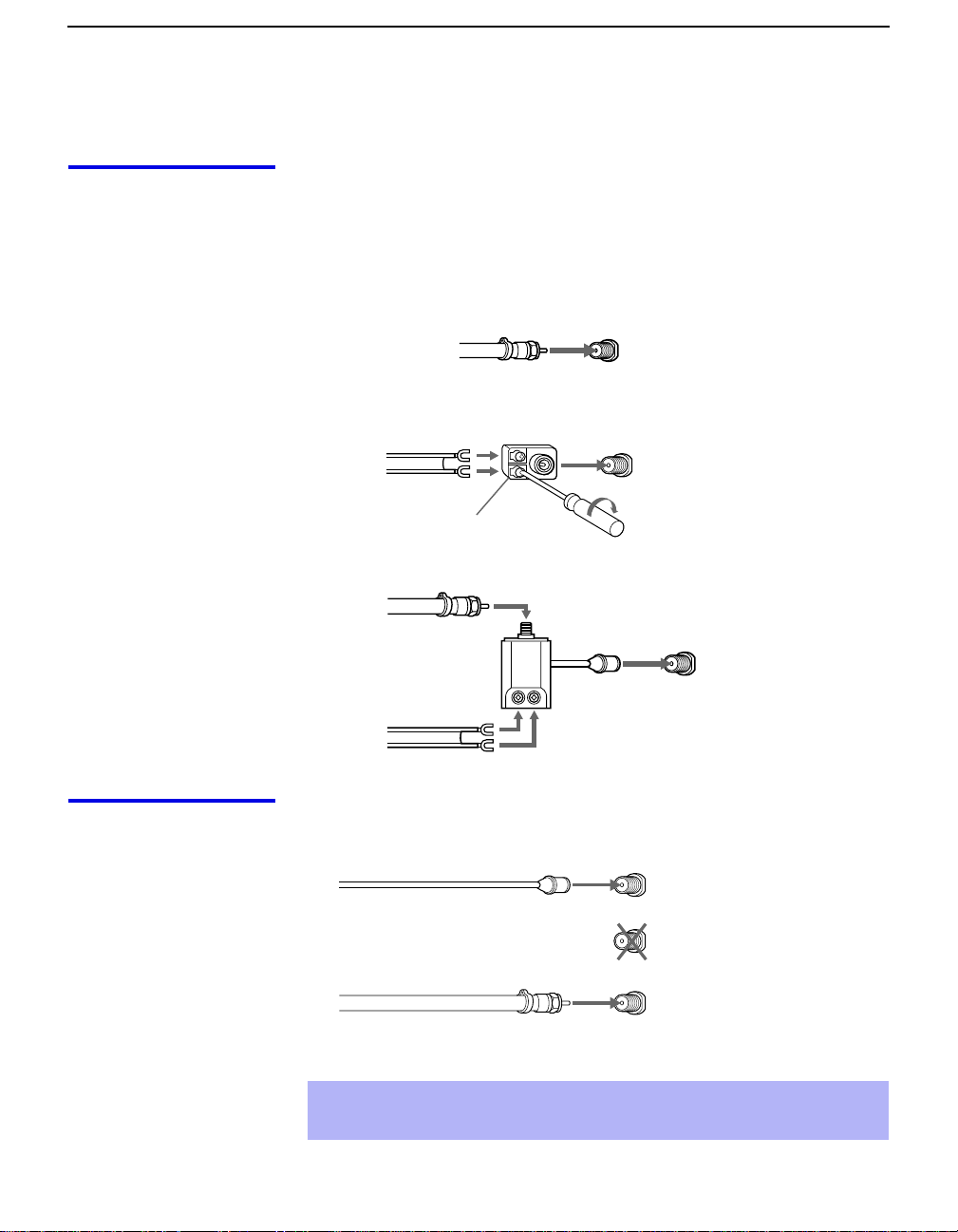
Basic Connections (Connecting Cable TV or Antenna)
Connecting Directly to Cable or an Antenna
The connection you choo se depends on t he cable foun d in your home. Ne wer
homes are equipped with standard coaxial cable (see A); older homes
probably have 300-ohm twin lead cable (see B); other homes may contain
both (see C).
A VHF Only or VHF/UHF or Cable
75-ohm coaxial
cable
B VHF Only or UHF Only or VHF/UHF
300-ohm twin lead cable
Antenna connector
C VHF and UHF
75-ohm coaxial cable
300-ohm twin lead cable
VHF/UHF
Rear of projection TV
VHF/UHF
U/V Splitter
(not supplied)
Rear of projection TV
VHF/UHF
Rear of projection TV
Cable and Antenna
16
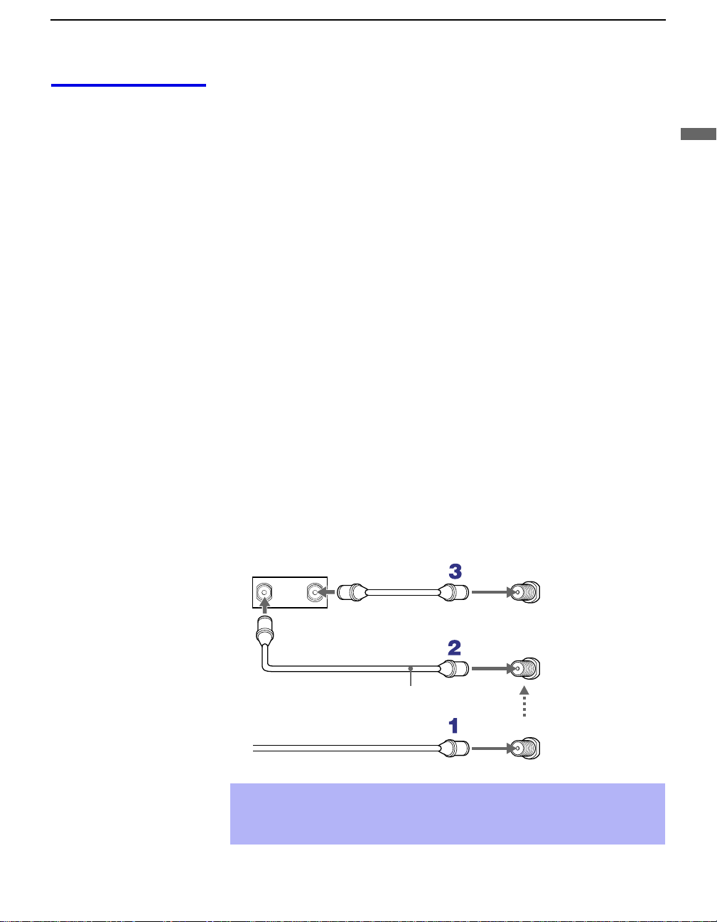
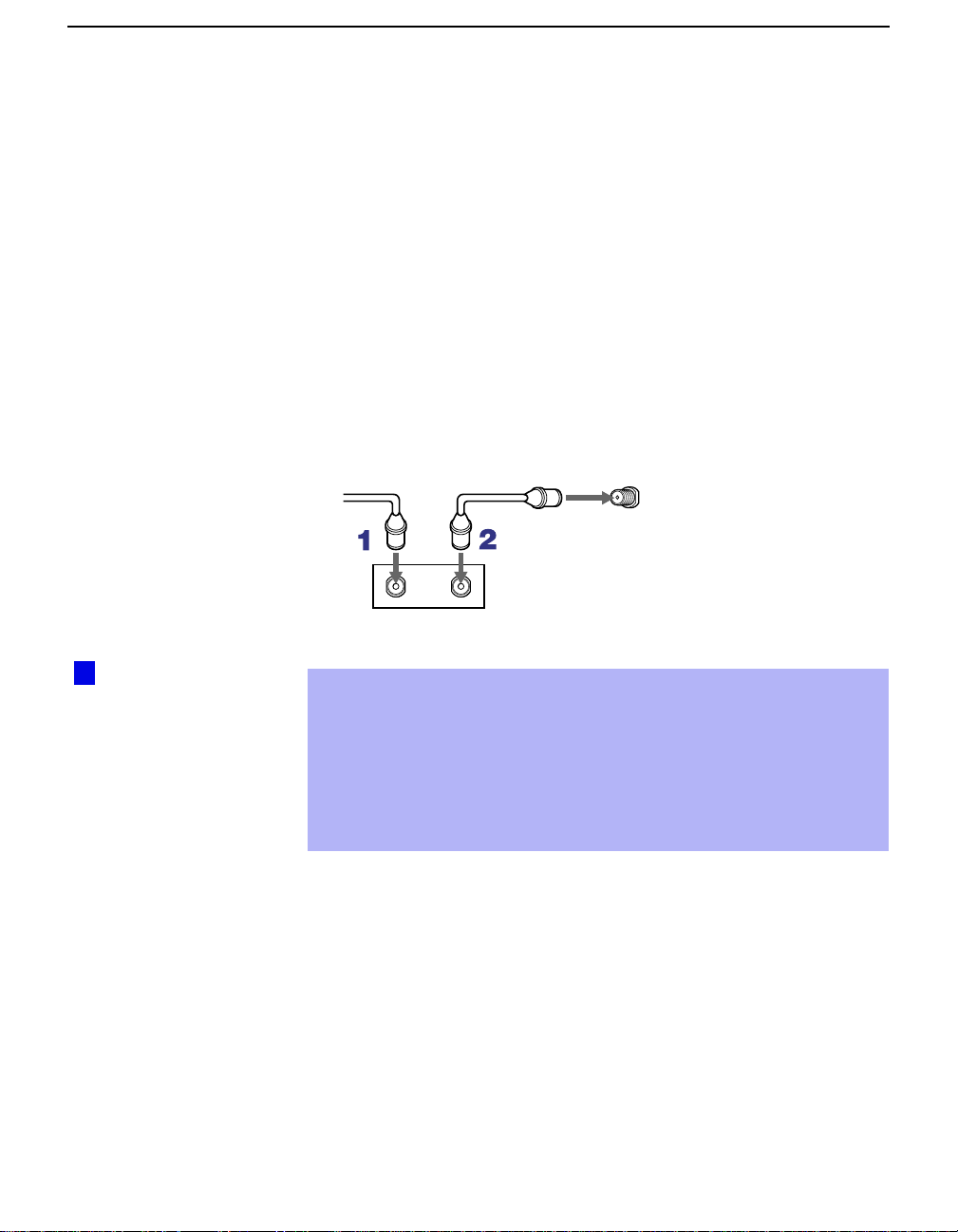
If your cable provider does not feature local channels, you may find this set
up convenient.
CATV cable
(No connection to
TO CONVERTER)
Antenna cable
Select CABLE or antenna (ANT) mode by pressing
AUX
TO
CONVERTER
VHF/UHF
Rear of projection TV
ANT
on the remote
control.
To receive channels with an antenna, you need to turn your Cable to OFF
✍
(see page 53) and perform the Auto Program function (see page 54).
Installing and Connecting the Projection TV
Cable Box Connections
Cable Box and Cable
This is the preferred basic cable TV hookup to use if:
❑
Your cable TV company scrambles some channels, but not all of them
(pay channels vs. regular cable channels) and you need to use a cable
box, and
❑
You want to enjoy the Twin View feature.
With this setup you can:
❑
Use the projection TV remote control to change channels using your
cable box when the signal is scrambled.
❑
Use the projection TV remote control to change channels using your
projection TV when the signal is not scrambled. (Your projection TV’s
tuner provides a better signal than the cable box.)
❑
Use the Twin View feature. (When all channels are routed through your
cable box, only one channel is sent to the proj ecti on TV, so yo u can no t
use the Twin View or Channel Index features for your cable box.)
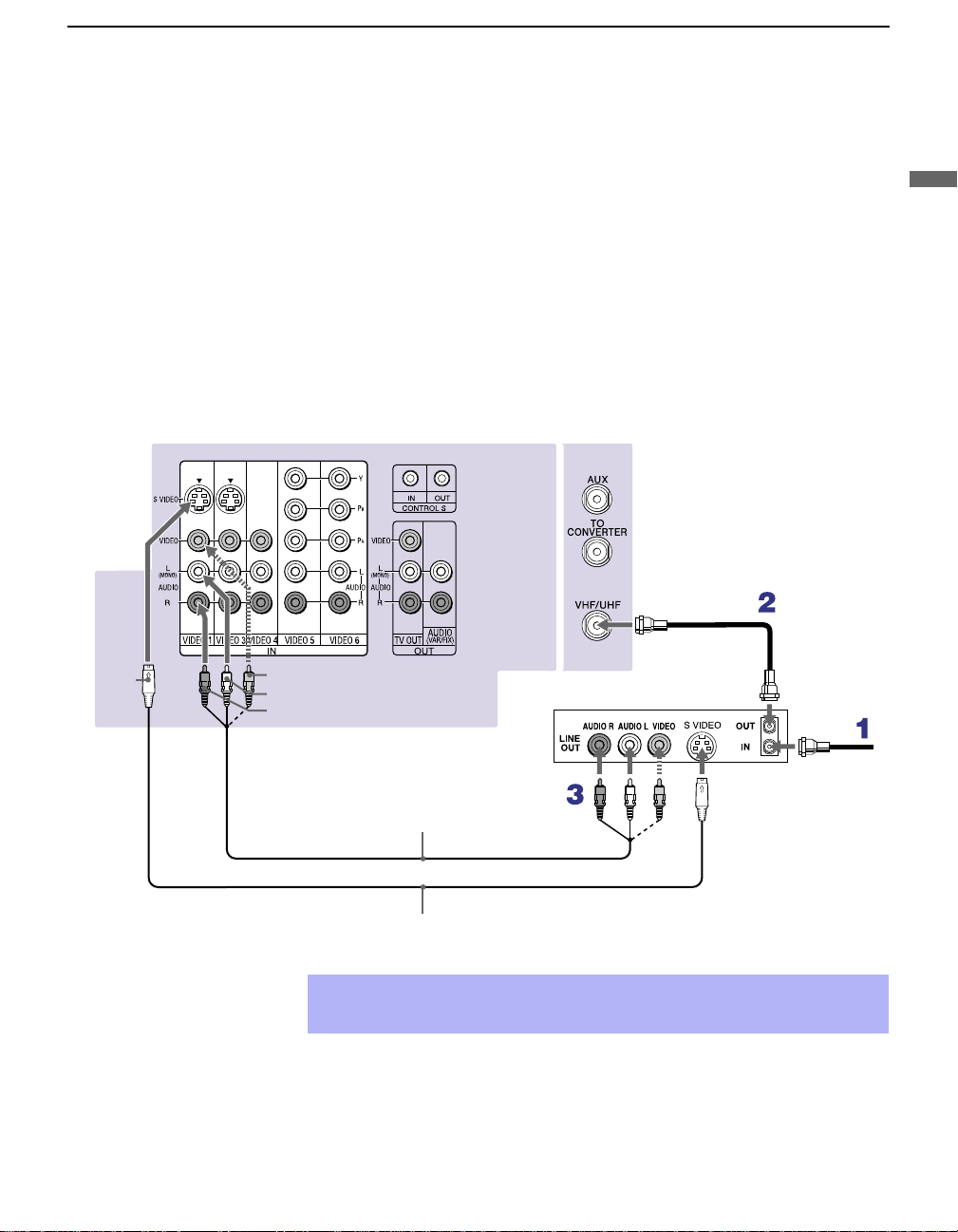
Connect the Cable TV cable to the projection TV’s VHF/UHF jack.
1
Using a coaxial cable, connect the projection TV’s TO CONVERTER
2
jack to the cable box’s IN jack. The projection TV’s internal converter
allows you to switch between unscrambled signals coming straight into
the projection TV and scrambled signals coming in through the cable
box, eliminating the need for an external splitter.
Installing and Connecting the Projection TV
Using a coaxial cable, connect the cable box’s OUT jack to the
3
projection TV’s AUX jack.
Cable box
IN
OUT
75-ohm coaxial cable (not supplied)
CATV cable (unscrambled channels)
✍
Pressing ANT on the remote control switches between the channels
AUX
Rear of
projection TV
TO
CONVERTER
Signal
VHF/UHF
coming in through the cable box (scrambled) and those coming directly
to the TV (unscrambled).
17
Installing and Connecting the Projection TV
Cable Box Only
Use this hookup if:
❑
You subscribe to a cable TV system that uses scrambled or encoded
signals requiring a cable box to view all channels, and
❑
You do not intend to hook up any other audio or video equipment to
your projection TV.
When all channels are routed through your cable box, only one unscrambled
channel is sent to the projection TV, so you cannot use the Twin View
feature. If some channels are scrambled, but others are not, consider using
the hookup on page 17 instead.
Connect the coaxial connector from your cable service to the cable
1
box’s IN jack.
Using a coaxial cable, connect the cable box’s OUT jack to the TV’s
2
VHF/UHF jack.
Cable
VHF/UHF
Rear of projection TV
z
Setting the Channel
Fix feature in the Channel
menu (see “Using the
Channel Menu” on page
53), ensures that you do
not accidentally switch
the channels using your
projection TV.
IN
Cable box
OUT
Also, set Cable to ON in the Channel menu (see page 53).
✍
Your So ny remote control can be progr ammed to operate your cable box
(see “Programmin g t he Remote Control” on page 68).
✍
To change channels using the cable box, set your projection TV to
channel 3 or 4 depending on the cable box chann el output. If you will be
controlling all channel selection through your cable box, consider using
the Channel Fix feature to set your projection TV to channel 3 or 4 (see
page 54).
18
Connecting a VCR and Cable
Use this hookup if:
❑
You have cable TV that does not require a cable box.
Disconnect all power sources before making any connections.
Connect the cable TV cable to the VCR’s IN jack.
1
Using a coaxial cable, connect the VCR’s OUT jack to the projection
2
TV’s VHF/UHF jack.
Using AUDIO and S VIDEO cables, connect the VCR’s Audio and
3
S Video OUT jacks to the projection TV’s AUDIO and S VIDEO IN
jacks.
Rear of Projection TV
Installing and Connecting the Projection TV
Installing and Connecting the Projection TV
Coaxial cable
S VIDEO
VIDEO (yellow)
AUDIO-L (white)
AUDIO-R (red)
YC-15V/30V (not supplied)
✍
If your VCR is not equipped with S VIDEO, use a VIDEO cable (yellow)
instead of the S VIDEO cable.
VMC-810S/820S
(not supplied)
VCR
Cable
19

Installing and Connecting the Projection TV
Connecting a VCR and Cable Box
Use this hookup if:
❑
Your cable TV company scrambles some channels, but not all of them
(pay channels vs. regular cable channels) and you need to use a cable
box, and
❑
You want to enjoy the Twin View feature.
With this setup you can:
❑
Use the projection TV remote control to change channels on your cable
box when the signal is scrambled. To pro gram your Sony remote cont rol
to operate your cable box, See “Programming the Remote Control” on
page 68.
❑
Use the projection TV remote control to change channels using your
projection TV when the signal is not scrambled. Your projection TV’s
tuner provides a better signal than the cable box.
❑
Use the Twin View feature. (When all channels are routed through your
cable box, only one signal is sent to the projection TV, so you cannot
use the Twin View feature.)
Disconnect all power sources before making any connections.
Connect the Cable TV cable to the projection TV’s VHF/UHF jack.
1
20
Using a coaxial cable, connect the TV’s TO CONVERTER jack to the
2
cable box’s IN jack. The projection TV’s internal converter allows you
to switch between unscrambled signals coming straight into the
projection TV and scrambled signals coming in through the cable box,
eliminating the need for an external splitter.
Using a coaxial cable, connect the cable box’s OUT jack to the VCR’s
3
IN jack.
Using AUDIO and S VIDEO cables, connect the VCR’s AUDIO and S
4
VIDEO OUT jacks to the projection TV’s AUDIO and S VIDEO IN
jacks.
Using a coaxial cable, connect the VCR’s OUT jack to the projection
5
TV’s AUX jack.
✍
To view scrambled channels, set your projection TV to AUX 3 or 4
(depending on your cable box output). Change channels using your
cable box.
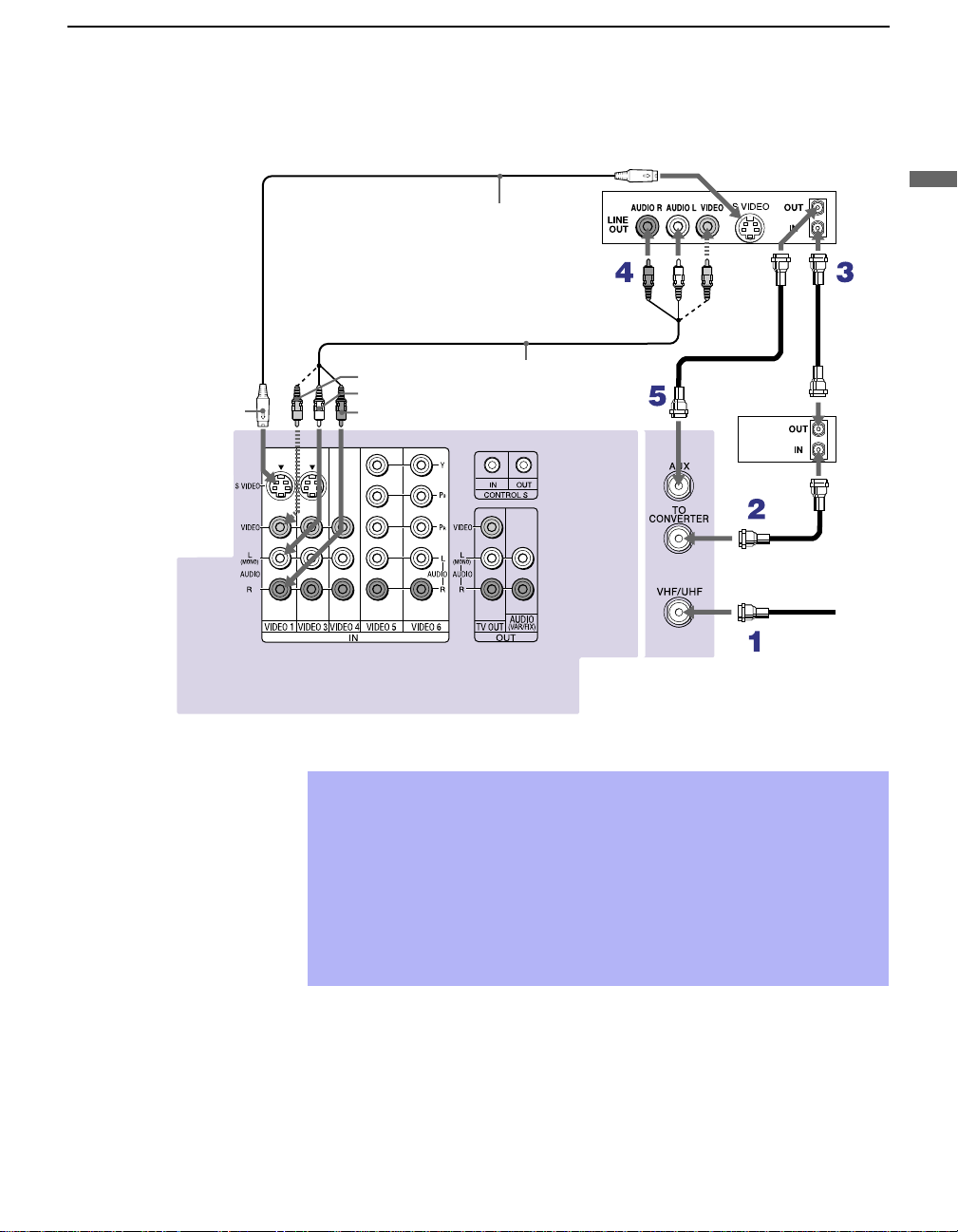
Installing and Connecting the Projection TV
S VIDEO
Rear of projection TV
VIDEO (yellow)
AUDIO-L (white)
AUDIO-R (red)
YC-15V/30V
(not supplied)
VMC-810S/820S
(not supplied)
Cable box
Coaxial cable
VCR
Coaxial
cable
Installing and Connecting the Projection TV
If your VCR is not equipped with S VIDEO, use a VIDEO cable (yellow)
✍
instead of the S VIDEO cable.
You will not b e able to change chan neles o n the VCR. Set your projec tion
✍
TV and VCR to channel 3 or 4, depending on your cable box channel
output.
Pressing ANT on the remote control switches between the channels
✍
coming in through the cable box (scrambled) and those coming directly
to the projection TV (unscrambled).
21
Installing and Connecting the Projection TV
Connecting Two VCRs for Tape Editing
If you connect two VCRs, you can record from one VCR to the other while
using your projection TV to monitor what is being recorded.
Disconnect all power sources before making any connections.
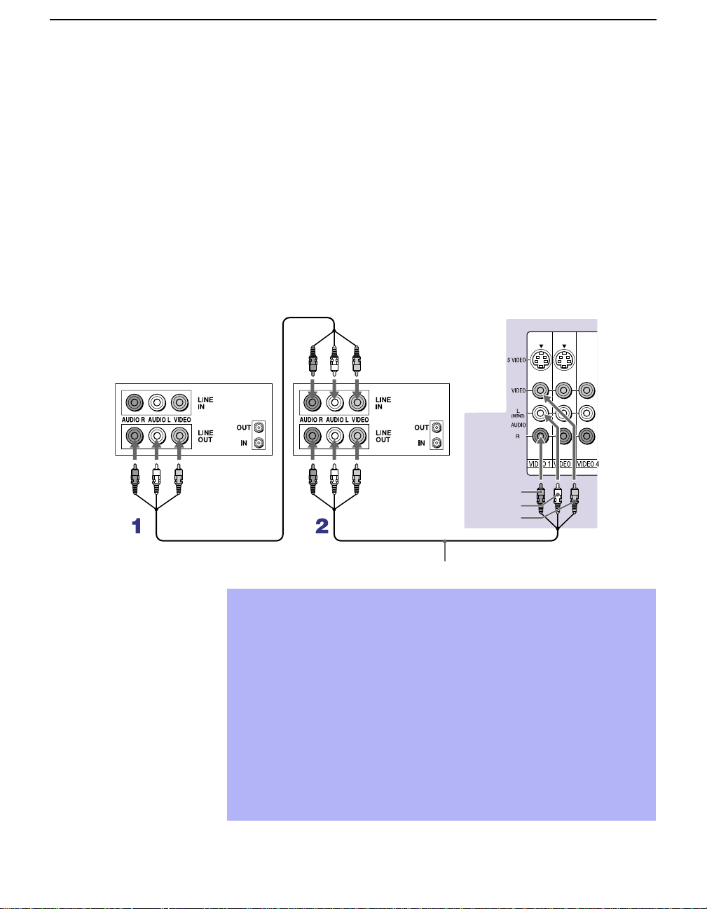
Using AUDIO and VIDEO cables, connect the playback VCR’s Au di o
1
and Video OUT jacks to the recording VCR’s Audio an d Video IN
jacks.
Using AUDIO and VIDEO cables, connect the recording VCR’s
2
AUDIO and Video OUT jacks to the projection TV’s AUDIO and
VIDEO IN jacks.
Rear of projection TV
VCR (playback)
VCR (recording)
AUDIO-R (red)
AUDIO-L (white)
VIDEO (yellow)
VMC-810S/820S (no t su pp lie d)
T o p erform tape edit ing, set the p rojection TV to the video i nput i ntend ed
✍
for playback by pressing TV/VIDEO on the remote control.
You may need to change the video input on your VCR. Consult your
✍
VCR’s operating manual for instructions.
If your VCRs have an S VIDEO jack: For best picture quality, use an
✍
S VIDEO connection instead of the yellow video cable on your combined
A/V cable.
Using an S VIDEO cable, connect the playback VCR’s S VIDEO OUT jack
to the recording VCR’s S VIDEO IN jack. S VIDEO does not provide audio,
so audio cables must be connected to provide sound.
You cannot record signals from equipment connected to the Y, PB, PR
✍
input.
22
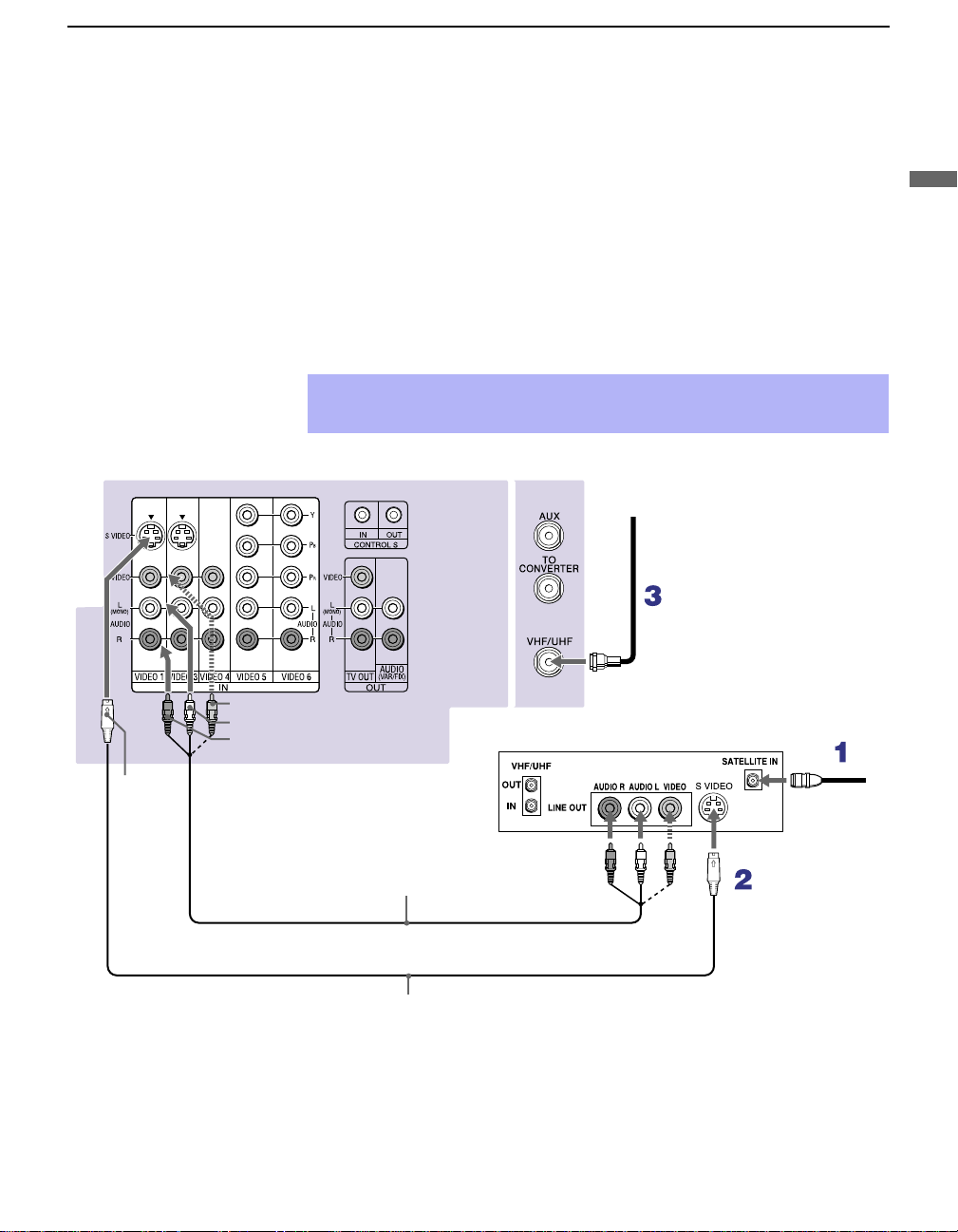
Connecting a Satellite Receiver
Disconnect all power sources before making any connections.
Installing and Connecting the Projection TV
ear of projection TV
1
2
3
✍
VIDEO (yellow)
AUDIO-L (white)
AUDIO-R (red)
Connect the satellite antenna cable to the satellite receiver’s
SATELLITE IN jack.
Using AUDIO and S VIDEO cables, connect the satellite receiver’s
A UD IO and S VIDEO OUT ja c ks to the projec t ion TV’s AUDIO and
S VIDEO IN jacks.
Connect a coaxial cable from your cable or antenna to the projection
TV’s VHF/UHF jack.
If your satellite receiver is not equipped with S VIDEO, use a VIDEO cable
(yellow) instead of the S VIDEO cable.
Coaxial
cable
Satellite receiver
Installing and Connecting the Projection TV
S
VIDEO
VMC-810S/820S (not supplied)
YC-15V/30V (not supplied)
Satellite
antenna
cable
23
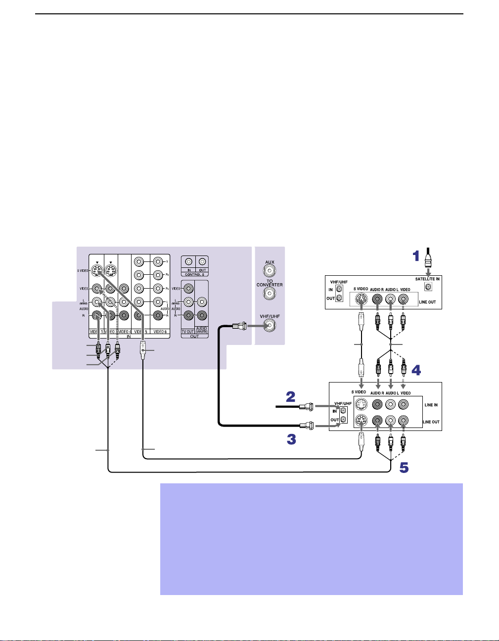
Installing and Connecting the Projection TV
Connecting a Satellite Receiver with a VCR
Disconnect all power sources before making any connections.
Connect the satellite antenna cable to the satellite receiver’s
1
SATELLITE IN jack.
Connect the CATV cable to the VCR’s VHF/UHF IN jack.
2
Using a coaxial cable, connect the VCR’s OUT jack to the projection
3
TV’s VHF/UHF jack.
Using AUDIO and S VIDEO cables, connect the satellite receiver’s
4
A UD IO and S VIDEO OUT ja c ks to the VCR’s AUDIO and S VIDEO
IN jacks.
Using AUDIO and S VIDEO cables, connect the VCR’s AUDIO and S
5
VIDEO OUT jacks to the TV’s AUDIO and S VIDEO IN jacks.
AUDIO-R (red)
AUDIO-L (white)
VIDEO (yellow)
VMC-810S/820S
(not supplied)
Rear of projection TV
Satellite receiver
Coaxial
cable
YC-15V/30V
S VIDEO
YC-15V/30V (not supplied)
Be sure your VCR’s video input is set correctly. Consult your VCR’s
✍
(not supplied)
VCR
Cable
operating manual for instructions.
Use TV/VIDEO to select
✍
- VIDEO 1 to watch satellite TV or the VCR (your VCR must be turned
on).
- VHF/UHF to watch cable TV.
If your VCR or satellite receiver is not equipped with S VIDEO, use a
✍
VIDEO cable (yellow) instead of the S VIDEO cable.
Satellite
antenna
cable
VMC-810S/
820S (not
supplied)
24
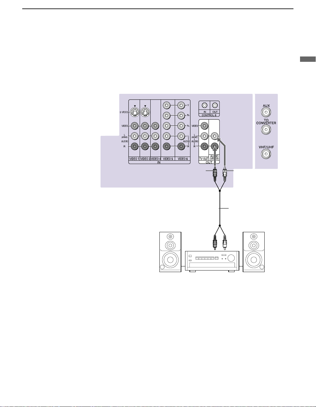
Connecting an Audio Receiver
Disconnect all power sources before making any connections.
Using audio cables, connect the projection TV’s AUDIO OUT (VAR/FIX)
jacks to the audio receiver’s audio LINE IN jacks.
Rear of projection TV
Installing and Connecting the Projection TV
Installing and Connecting the Projection TV
AUDIO-R
(red)
Line
input
AUDIO-L
(white)
RK-74A
(not supplied)
25
 Loading...