

Sony KLV-46X300A, KLV-46W380A, KLV-52X300A, KLV-52W380A Service Manual
D846660B279CC0D5520DEF8E80C6FD0B0509C3DE5F2E1AA6843A75ED6228AB147AA810E8D0815DE5
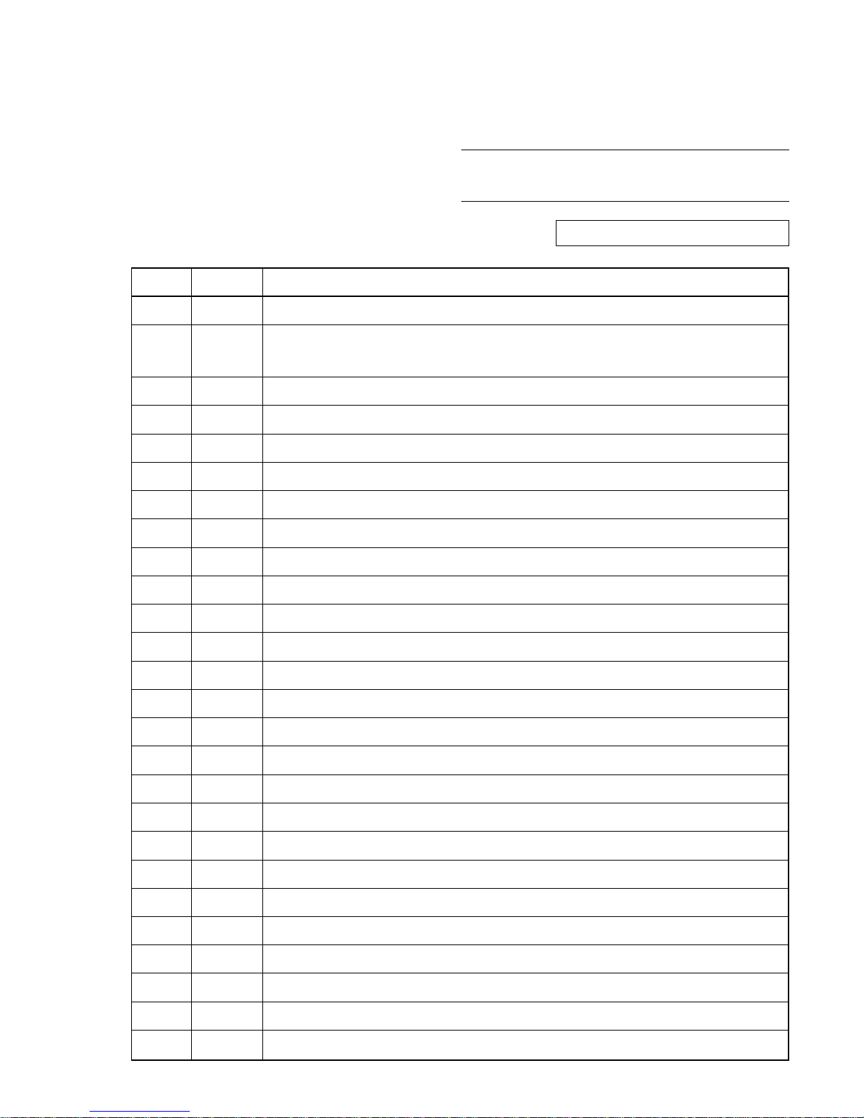
Ver. DATA CONTENTS
1.0 2007.09 Issued
1.1 2008.06 Addition of KLV-46W380A/52W380A Models.
(P. 2 to P. 3, P. 6, P. 1-13, P. 1-19, P. 4-1, P. 5-15, P. 5-22, P. 5-31)
MODEL NAME : KLV-46/52X300A, 46/52W380A
SERVICE MANUAL
PA RTS No. : 9-834-177-02
MODIFICATION HISTORY
* Blue characters are linking.
D846660B279CC0D5520DEF8E80C6FD0B0509C3DE5F2E1AA6843A75ED6228AB147AA810E8D0815DE5
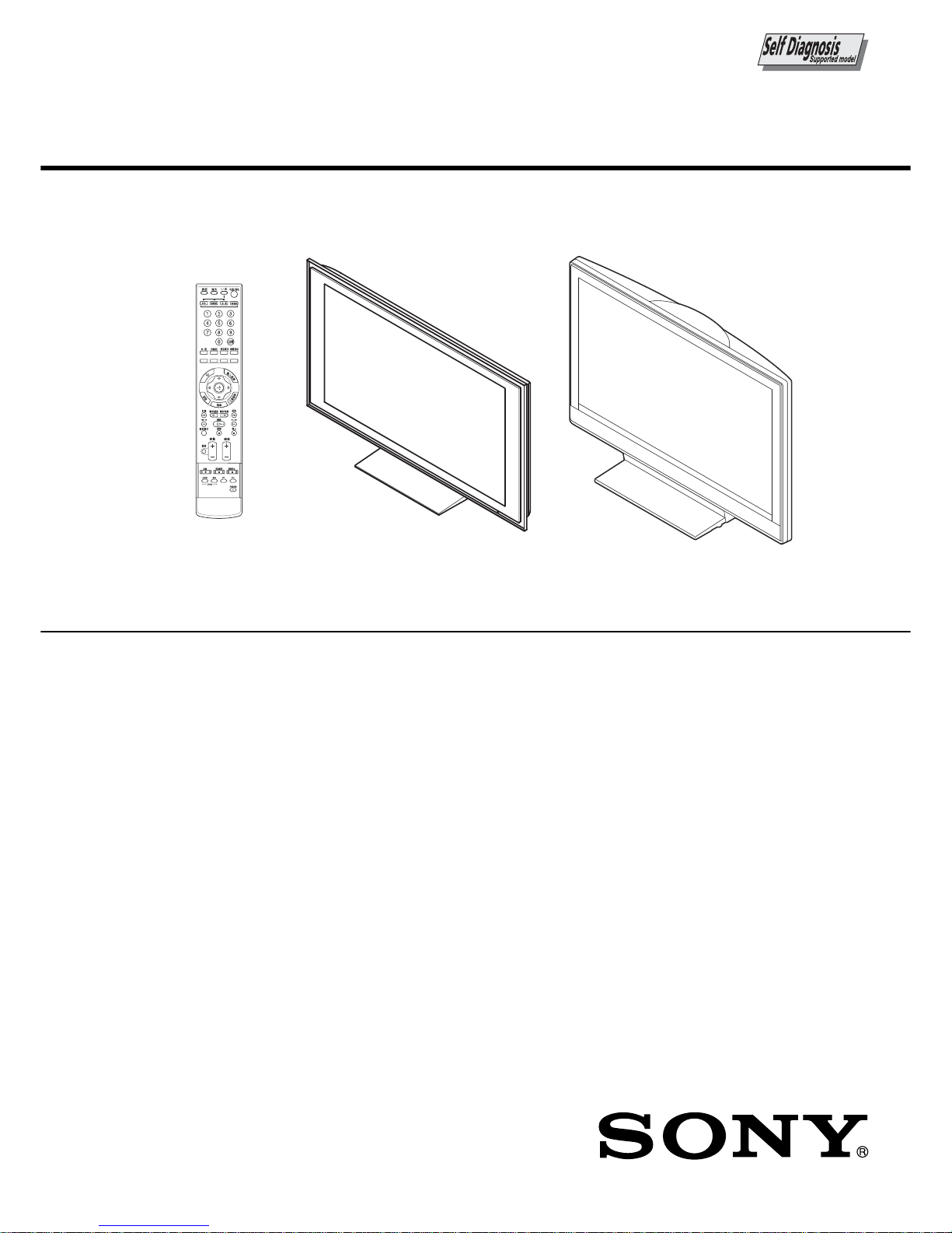
SERVICE MANUAL
FIX2 CHASSIS
KLV-46X300A/52X300A/46W380A/52W380A
LCD Colour TV
China Model
RM-SA013 KLV-46X300A/52X300A KLV-46W380A/52W380A
D846660B279CC0D5520DEF8E80C6FD0B0509C3DE5F2E1AA6843A75ED6228AB147AA810E8D0815DE5
KLV-46/52X300A, 46/52W380A (CH) 2
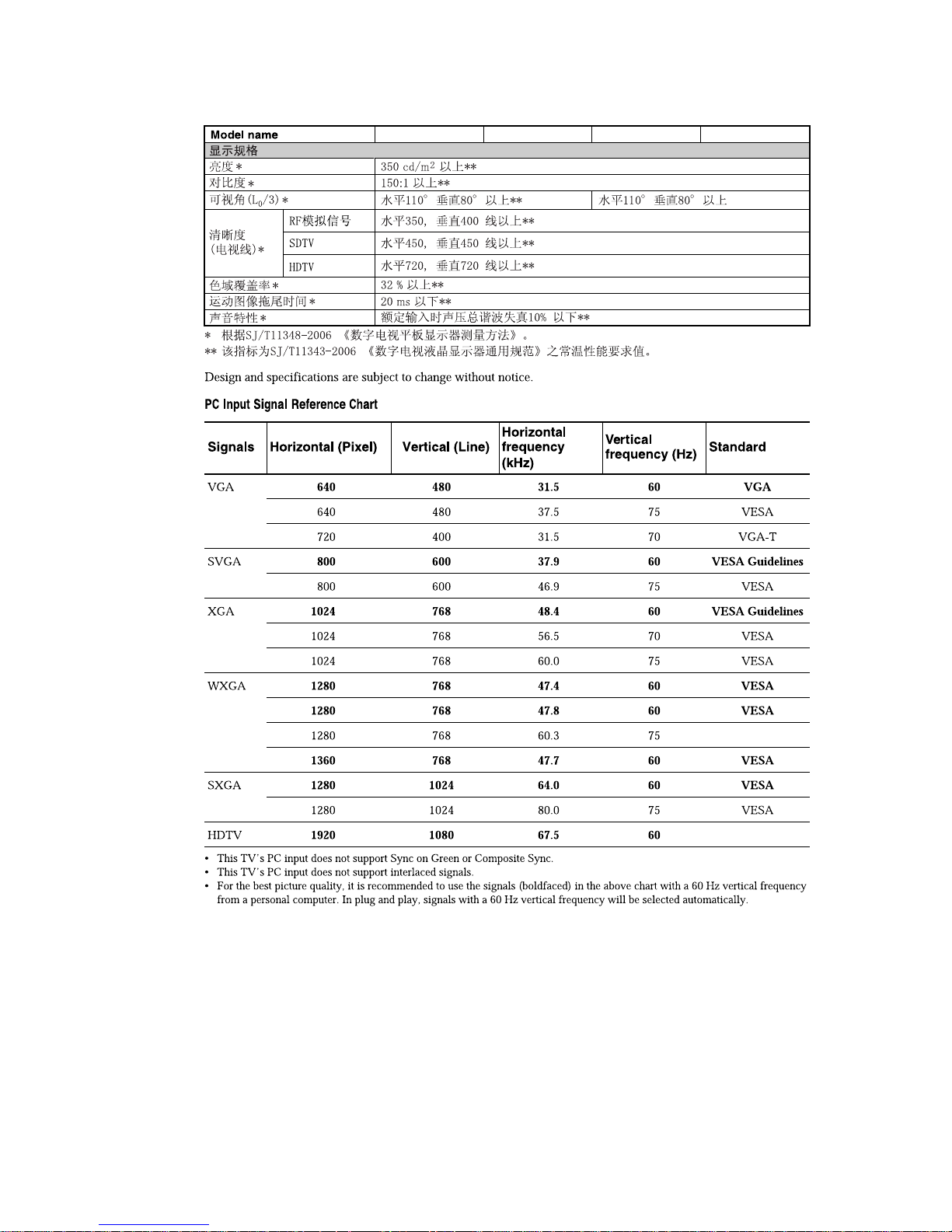
SPECIFICATIONS
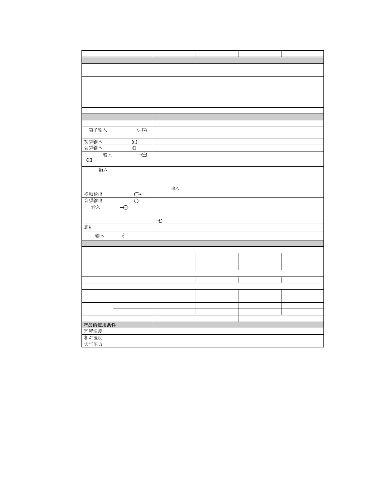
KLV-46X300A KLV-52X300A KLV-46W380A KLV-52W380A
Model name
* Specified standby power is reached after the TV finishes necessary internal processes.
** The values of dimensions and mass are approximate.
System
Panel System LCD (Liquid Crystal Display) Panel
TV System D/K, B/G, I, M
Colour System PAL, SECAM, NTSC 3.58, NTSC 4.43 (only Video In)
Channel Coverage D/K: VHF: C1 to C12, R1 to R12/ UHF: C13 to C57, R21 to R60/
CATV: S01 to S03, S1 to S41, Z1 to Z39
B/G: VHF: E2 to E12/ UHF: E21 to E69/ CATV: S01 to S03, S1 to S41
I: UHF: B21 to B69/ CATV: S01 to S03, S1 to S41
M: VHF: A2 to A13/ UHF: A14 to A79/ CATV: A-8 to A-2, A to W+4, W+6 to W+84
Sound Output 9 W + 9 W (THD; Total Harmonic Distortion: 7%)
Input/Output jacks
Antenna 75 ohm external terminal for VHF/UHF
S (S VIDEO IN) 1, S video input (4-pin mini DIN)
2
(VIDEO IN) 1, 2, 3 Video input (phono jack)
(AUDIO IN) 1, 2, 3 Audio input (phono jacks): 500 mVrms, Impedance: 47 kilohms
HD/DVD (HD/DVD In) 1/ Supported formats: 1080p, 1080i, 720p, 576p, 576i, 480p, 480i
2
Y: 1 Vp-p, 75 ohms, 0.3V negative sync/P
B/CB
: 0.7 Vp-p, 75 ohms/
PR/CR: 0.7 Vp-p, 75 ohms
HDMI (HDMI IN) 1, 2, 3 Video: 1080/24p, 1080p, 1080i, 720p, 576p, 576i, 480p, 480i
Audio: Two channel linear PCM
32, 44.1 and 48 kHz, 16, 20 and 24 bits
Analogue audio input (phono jacks): 500 mVrms, Impedance: 47 kilohms
(HDMI (HDMI IN) 1 only)
(VIDEO OUT) Video output (phono jacks)
(AUDIO OUT) Audio output (phono jacks)
PC (PC IN) (RGB) PC Input (D-sub 15-pin)
G: 0.7 Vp-p, 75 ohms, non Sync on Green/B: 0.7 Vp-p, 75 ohms/
R: 0.7 Vp-p, 75 ohms/HD: 1-5 Vp-p/VD: 1-5 Vp-p
PC audio input (minijack)
(Headphone) i Headphones jack
USB (USB) USB port
Power and others
Power Requirements 220 V AC, 50 Hz
Screen Size 46 inches 52 inches 46 inches 52 inches
(Approx. 116.8 cm (Approx. 132.2 cm (Approx. 116.8 cm (Approx. 132.2 cm
measured diagonally) measured diagonally) measured diagonally) measured diagonally)
Display Resolution 1,920 dots (horizontal) × 1,080 lines (vertical)
Power Consumption 300 W 350 W 300W 350W
Standby Power Consumption* 0.5 W
Dimensions** with stand (mm) 1,262 × 795 × 322 1,415 × 890 × 384 1,135 × 779 × 306 1,278 × 874 × 384
(w × h × d)
without stand (mm) 1,262 × 734 × 123 1,415 × 827 × 125 1,135 × 734 × 122 1,278 × 832 × 123
Mass** with stand (kg) 38.0 49.0 32.5 43.5
without stand (kg) 33.0 42.0 28.5 36.0
Optional Accessories Wall-Mount Bracket SU-WL500
5°C - 35°C
20% - 80%
86 kPa - 106 kPa
D846660B279CC0D5520DEF8E80C6FD0B0509C3DE5F2E1AA6843A75ED6228AB147AA810E8D0815DE5
KLV-46/52X300A, 46/52W380A (CH) 3
KLV-46X300A KLV-52X300A KLV-46W380A KLV-52W380A

D846660B279CC0D5520DEF8E80C6FD0B0509C3DE5F2E1AA6843A75ED6228AB147AA810E8D0815DE5
KLV-46/52X300A, 46/52W380A (CH) 4
CAUTION
These servicing instructions are for use by qualified service
personnel only.
To reduce the risk of electric shock, do not perform any servicing
other than that contained in the operating instructions unless you
are qualified to do so.
WARNING!!
An isolation transformer should be used during any service to
avoid possible shock hazard, because of live chassis.
The chassis of this receiver is directly connected to the ac power
line.
! SAFETY-RELATED COMPONENT
WARNING!!
Replace all components with Sony parts whose part numbers
appear as shown in this manual or in supplements
published by Sony.
WARNINGS AND CAUTIONS SAFETY-RELATED COMPONENT
WARNING
It is essential that all critical parts be replaced only with the part
number specified in the electrical parts list to prevent electric
shock, fire, or other hazard.
NOTE: Do not modify the original design without obtaining
written permission from the manufacturer or you will
void the original parts and labor guarantee.
USE CAUTION WHEN HANDLING THE LCD PANEL
When repairing the LCD panel, be sure you are grounded by
using a wrist band.
When repairing the LCD panel on the wall, the LCD panel must
be secured using the 4 mounting holes on the rear cover.
1) Do not press on the panel or frame edge to avoid the risk of
electric shock.
2) Do not scratch or press on the panel with any sharp objects.
3) Do not leave the module in high temperatures or in areas of
high humidity for an extended period of time.
4) Do not expose the LCD panel to direct sunlight.
5) Avoid contact with water. It may cause a short circuit within
the module.
6) Disconnect the AC power when replacing the backlight (CCFL)
or inverter circuit.
(High voltage occurs at the inverter circuit at 650Vrms.)
7) Always clean the LCD panel with a soft cloth material.
8) Use care when handling the wires or connectors of the inverter
circuit. Damaging the wires may cause a short.
9) Protect the panel from ESD to avoid damaging the electronic
circuit (C-MOS).
D846660B279CC0D5520DEF8E80C6FD0B0509C3DE5F2E1AA6843A75ED6228AB147AA810E8D0815DE5
KLV-46/52X300A, 46/52W380A (CH) 5
SAFETY CHECK-OUT
After correcting the original service problem, perform the
following safety checks before releasing the set to the customer:
1. Check the area of your repair for unsoldered or poorly
soldered connections. Check the entire board surface for
solder splashes and bridges.
2. Check the interboard wiring to ensure that no wires are
“pinched” or touching high-wattage resistors.
3. Check that all control knobs, shields, covers, ground straps,
and mounting hardware have been replaced. Be absolutely
certain that you have replaced all the insulators.
4. Look for unauthorized replacement parts, particularly
transistors, that were installed during a previous repair. Point
them out to the customer and recommend their replacement.
5. Look for parts which, though functioning, show obvious
signs of deterioration. Point them out to the customer and
recommend their replacement.
6. Check the line cords for cracks and abrasion. Recommend
the replacement of any such line cord to the customer.
7. Check the antenna terminals, metal trim, “metallized”
knobs, screws, and all other exposed metal parts for AC
leakage. Check leakage as described below.
Leakage Test
The AC leakage from any exposed metal part to earth ground
and from all exposed metal parts to any exposed metal part
having a return to chassis, must not exceed 0.5 mA (500
microamperes).
Leakage current can be measured by any one of three methods.
1. A commercial leakage tester, such as the Simpson 229 or
RCA WT-540A. Follow the manufacturers’ instructions to
use these instructions.
2. A battery-operated AC milliampmeter. The Data Precision
245 digital multimeter is suitable for this job.
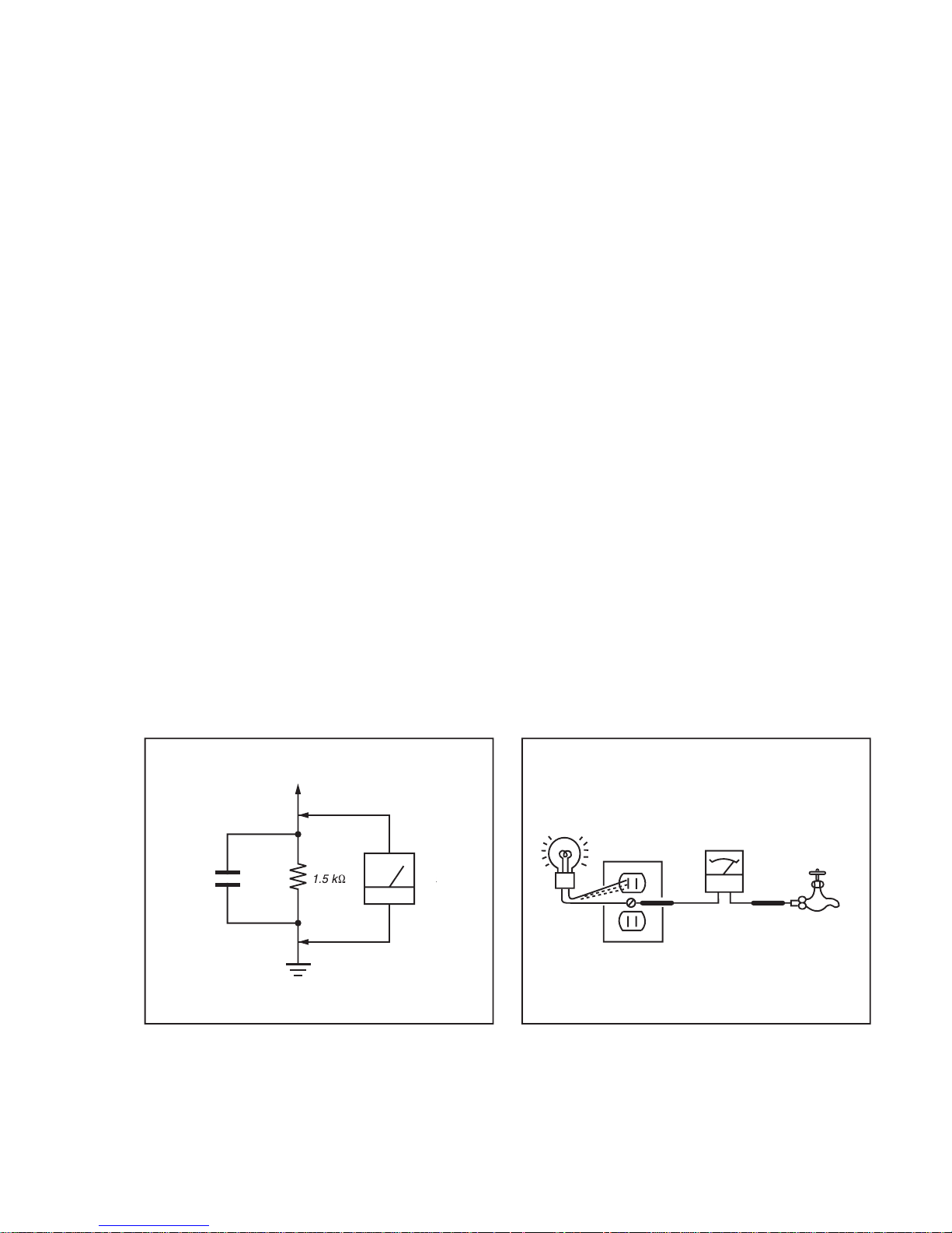
3. Measuring the voltage drop across a resistor by means of a
VOM or battery-operated AC voltmeter. The “limit”
indication is 0.75 V, so analog meters must have an accurate
low voltage scale.
The Simpson’s 250 and Sanwa SH-63TRD are examples of
passive VOMs that are suitable. Nearly all battery-operated
digital multimeters that have a 2 VAC range are suitable (see
Figure A).
How to Find a Good Earth Ground
A cold-water pipe is a guaranteed earth ground; the cover-plate
retaining screw on most AC outlet boxes is also at earth ground.
If the retaining screw is to be used as your earth ground, verify
that it is at ground by measuring the resistance between it and a
cold-water pipe with an ohmmeter. The reading should be zero
ohms.
If a cold-water pipe is not accessible, connect a 60- to 100-watt
trouble- light (not a neon lamp) between the hot side of the
receptacle and the retaining screw. Try both slots, if necessary,
to locate the hot side on the line; the lamp should light at normal
brilliance if the screw is at ground potential (see Figure B).
Exposed Meta
l
Parts on Se
t
.15
µ
Earth Groun
d
AC
0.75V
)
ouble Ligh
t
AC Outlet Box
Ohmmeter
Col
d-water Pi
pe
FigureA. Using an AC voltmeter to check AC leakage. Figure B. Checking for earth ground
.
D846660B279CC0D5520DEF8E80C6FD0B0509C3DE5F2E1AA6843A75ED6228AB147AA810E8D0815DE5
KLV-46/52X300A, 46/52W380A (CH) 6
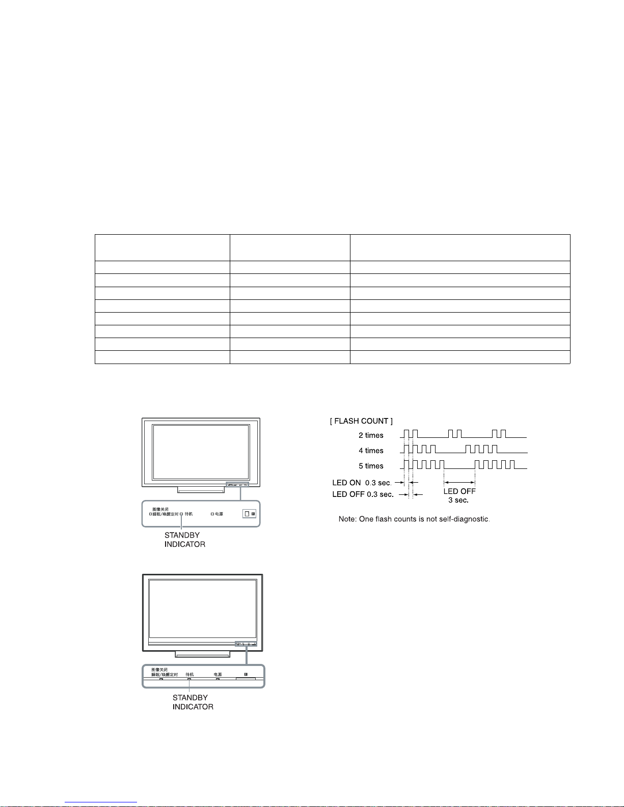
SELF DIAGNOSIS FUNCTION
The units in this manual contain a self-diagnostic function. If an error occurs, the STANDBY LED will automatically begin to flash.
The number of times the LED flashes translates to a probable source of the problem.
A definition of the STANDBY LED flash indicators is listed in the instruction manual for the user’s knowledge and reference.
If an error symptom cannot be reproduced, the remote commander can be used to review the failure occurrence data stored in memory to
reveal past problems and how often these problems occur.
1-1. DIAGNOSTIC TEST INDICATORS
When an error occurs, the STANDBY LED will flash a set number of times to indicate the possible cause of the problem.
If there is more than one error, the LED will identify the first of the problem areas.
Result for all of the following diagnostic items are displayed on screen.
If the screen displays a “0”, no error has occurred .
Number of times STANDY LED Monitoring Items
Diagnostic Item Description
(Red) flashes (Screen Display)
2 times POW OVP Main Power Over Voltage Protection
3 times POW ERR1 Power Error
5 times T_CON T_CON Error
6 times BACKLITE Back Light Error (Panel Inverter)
7 times TEMP ERR Temperature Abnormal Detection
8 times AUD PROT Audio Abnormal Detection
9 times FAN_ERR FAN Error (Not Detected. Display Only)
13 times BALANCER Panel Balancer Error
1-2. DISPLAY OF STANDBY LED FLASH COUNT
1-3. STOPPING THE STANDBY FLASH
Turn off the power switch on the TV main unit or unplug the power cord from the outlet to stop the STANDBY lamp from flashing.
< KLV-46/52X300A >
< KLV-46/52W380A >
D846660B279CC0D5520DEF8E80C6FD0B0509C3DE5F2E1AA6843A75ED6228AB147AA810E8D0815DE5
KLV-46/52X300A, 46/52W380A (CH) 7
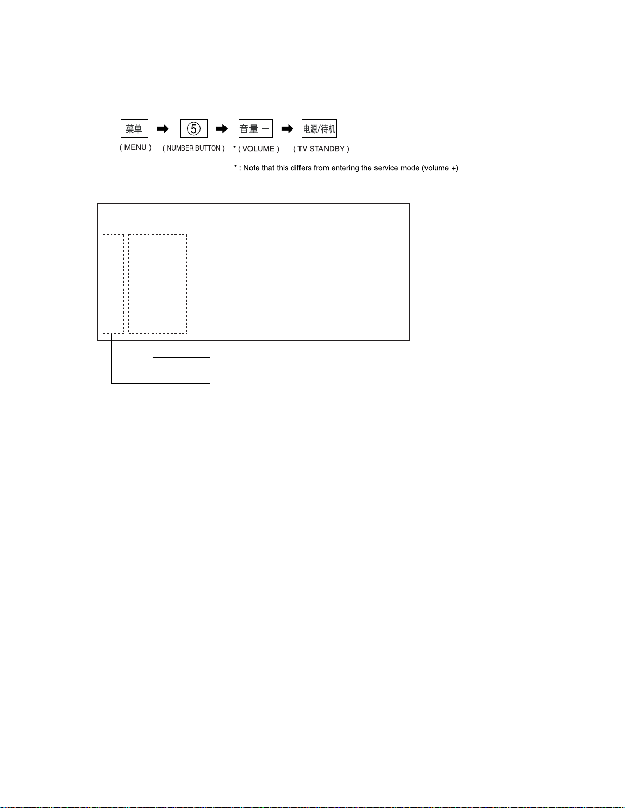
1-4. SELF-DIAGNOSTIC SCREEN DISPLAY
For errors with symptoms such as “power sometimes shuts off” or “screen sometimes goes out” that cannot be confirmed, it is possible to
bring up past occurrences of failure for confirmation on the screen:
1-4-1. To Bring Up Screen Test
In standby mode, press buttons on the remote commander sequentially in rapid succession as shown below:
Since the diagnostic results displayed on the screen are not automatically cleared, always check the self-diagnostic screen
After you have completed the repairs, clear the result display to “0”.
1-5. Quitting Self-diagnostic screen
To quit the entire self-diagnostic screen, turn off the power switch on the remote commander or the main unit.
SELF CHECK
002
003
005
006
007
008
009
013
POW OVP
POW ERR1
T_CON
BACKLITE
TEMP ERR
AUD PROT
FAN_ERR
BALANCER
0000000000
0000000000
0000000000
0000000000
0000000000
0000000000
0000000000
0000000000
0000000000
0000000000
0000000000
0000000000
0000000000
0000000000
0000000000
0000000000
0000000000
0000000000
0000000000
0000000000
0000000000
0000000000
0000000000
0000000000
00
00
00
00
00
00
00
00
Monitoring Items
For details, refer to "1-1. DIAGNOSTIC TEST INDICATORS"
[ SELF-DIAGNOSTIC SCREEN DISPLAY ]
Number of times STANDBY Indicator flashes

D846660B279CC0D5520DEF8E80C6FD0B0509C3DE5F2E1AA6843A75ED6228AB147AA810E8D0815DE5
KLV-46/52X300A, 46/52W380A (CH) 8
TABLE OF CONTENTS
SAFETY CHECK-OUT ............................................. 5
SELF DIAGNOSIS FUNCTION ................................ 6
1. DISASSEMBLY ...............................................1-1
1-1. KLV-46X300A ....................................................... 1-1
1-1-1. REAR COVER ASSY REMOVAL ................ 1-1
1-1-2. STAND ASSY AND ARM ASSY
REMOVAL ...................................................... 1-1
1-1-3. H1 BOARD REMOVAL ................................. 1-2
1-1-4. HW2 BOARD REMOVAL ............................. 1-2
1-1-5. DF1 BOARD AND GF1 BOARD
REMOVAL ...................................................... 1-3
1-1-6. AG BOARD AND FB2 BOARD
REMOVAL ...................................................... 1-3
1-1-7. TUG BOARD REMOVAL.............................. 1-4
1-1-8. SPEAKER AND FAN REMOVAL ................ 1-4
1-1-9. UB1 BOARD REMOVAL .............................. 1-5
1-1-10. H3 BOARD AND H4 BOARD AND
AC INLET REMOVAL ................................... 1-5
1-1-11. LCD PANEL AND FRONT CABINET ASSY
REMOVAL ...................................................... 1-6
1-2. KLV-52X300A ....................................................... 1-7
1-2-1. REAR COVER ASSY REMOVAL ................ 1-7
1-2-2. STAND ASSY AND ARM ASSY
REMOVAL ...................................................... 1-7
1-2-3. H1 BOARD REMOVAL ................................. 1-8
1-2-4. HW2 BOARD REMOVAL ............................. 1-8
1-2-5. DF2, DF3 AND GF1 BOARDS REMOVAL . 1-9
1-2-6. AG AND FB2 BOARDS REMOVAL ............ 1-9
1-2-7. TUG BOARD REMOVAL............................ 1-10
1-2-8. SPEAKER AND FAN REMOVAL .............. 1-10
1-2-9. UB1 BOARD REMOVAL ............................ 1-11
1-2-10. H3 BOARD AND H4 BOARD AND
AC INLET REMOVAL ................................. 1-11
1-2-11. LCD PANEL AND FRONT CABINET ASSY
REMOVAL .................................................... 1-12
1-3. KLV-46W380A .................................................... 1-13
1-3-1. REAR COVER ASSY REMOVAL .............. 1-13
1-3-2. STAND ASSY AND ARM ASSY
REMOVAL .................................................... 1-13
1-3-3. HW1 BOARD REMOVAL ........................... 1-14
1-3-4. HW2 BOARD REMOVAL ........................... 1-14
1-3-5. DF2, DF3 AND GF1 BOARDS
REMOVAL .................................................... 1-15
1-3-6. AG AND FB2 BOARDS REMOVAL .......... 1-15
1-3-7. TUG BOARD REMOVAL............................ 1-16
1-3-8. CHASSIS BRACKET AND STAY
REMOVAL .................................................... 1-16
1-3-9. FAN AND SPEAKER REMOVAL .............. 1-17
1-3-10. UB2 BOARD REMOVAL ............................ 1-17
1-3-11. LCD PANEL AND HW3 BOARD
REMOVAL .................................................... 1-18
1-4. KLV-52W380A .................................................... 1-19
1-4-1. REAR COVER ASSY REMOVAL .............. 1-19
1-4-2. STAND ASSY AND ARM ASSY
REMOVAL .................................................... 1-19
1-4-3. HW1 BOARD REMOVAL ........................... 1-20
1-4-4. HW2 BOARD REMOVAL ........................... 1-20
1-4-5. DF4, DF5 AND GF2 BOARDS
REMOVAL .................................................... 1-21
1-4-6. FB TOP SHIELD REMOVAL ...................... 1-21
1-4-7. AG AND FB2 BOARDS REMOVAL .......... 1-22
1-4-8. TUG BOARD REMOVAL............................ 1-22
1-4-9. UB2 BOARD REMOVAL ............................ 1-23
1-4-10. CHASSIS BRACKET AND STAY
REMOVAL .................................................... 1-23
1-4-11. SPEAKER REMOVAL ................................. 1-24
1-4-12. LCD PANEL AND HW3 BOARD
REMOVAL .................................................... 1-24
2. SERVICE MODE ADJUSTMENT ...................2-1
2-1. Go to TV standby condition. .................................. 2-1
2-2. Entering Service Mode ........................................... 2-1
2-3. Change Setting Data for TV................................... 2-2
2-4. Write data for TVM ................................................ 2-3
2-5. Entering BEM service menu .................................. 2-4
2-6. Change Setting Data for BEM ............................... 2-5
2-7. Write data for BEM ................................................ 2-6
2-8. CH Model ............................................................... 2-7
2-9. How to change shipping condition. ....................... 2-8
3. TROUBLE SHOOTING ................................... 3-1
3-1. No Power (Flow Chart_B) ..................................... 3-2
3-2. Set Reboots ............................................................. 3-3
3-3. SELF DIAGNOSIS ................................................ 3-4
3-3-1. Flow Chart_C ................................................... 3-5
3-3-2. POWER OVP (RED 2 Times blink) ............... 3-6
3-3-3. POWER ERROR (RED 3 Times blink) .......... 3-6
3-3-4. T-CON ERROR (RED 5 Times blink) ............ 3-7
3-3-5. BACK LIGHT ERROR
(RED 6 Times blink) ........................................ 3-7
3-3-6. TEMP ERROR (RED 7 Times blink) ............. 3-8
3-3-7. AUDIO ERROR (RED 8 Times blink) ........... 3-8
3-3-8. DTAU ERROR (RED 10 Times blink) ........... 3-9
3-3-9. BALANCER ERROR
(RED 13 Times blink) .................................... 3-10
3-4. COMMUNICATION ERROR ............................. 3-11
3-5. AUDIO PROBLEM (Flow Chart_D) .................. 3-12
3-6. VIDEO PROBLEM (Flow Chart_E) ................... 3-13
4. DIAGRAMS ..................................................... 4-1
4-1. CIRCUIT BOARDS LOCATION ......................... 4-1
(1) KLV-46X300A ................................................ 4-1
(2) KLV-52X300A ................................................ 4-1
(3) KLV-46W380A................................................ 4-1
(4) KLV-52W380A................................................ 4-1

D846660B279CC0D5520DEF8E80C6FD0B0509C3DE5F2E1AA6843A75ED6228AB147AA810E8D0815DE5
KLV-46/52X300A, 46/52W380A (CH) 9
5. EXPLODED VIEWS ........................................ 5-1
5-1. KLV-46X300A ....................................................... 5-2
5-1-1. REAR COVER ASSY ..................................... 5-2
5-1-2. ARM ASSY AND STAND ASSY AND
HW2 BOARD .................................................. 5-3
5-1-3. CHASSIS-1 ...................................................... 5-4
5-1-4. CHASSIS-2 ...................................................... 5-5
5-1-5. FAN AND SPEAKER ..................................... 5-6
5-1-6. FRONT CABINET ASSY AND
LCD PANEL .................................................... 5-7
5-1-7. CONNECTOR ASSY ...................................... 5-8
5-2. KLV-52X300A ....................................................... 5-9
5-2-1. REAR COVER ASSY ..................................... 5-9
5-2-2. ARM ASSY AND STAND ASSY AND
HW2 BOARD ................................................ 5-10
5-2-3. CHASSIS-1 .................................................... 5-11
5-2-4. CHASSIS-2 .................................................... 5-12
5-2-5. FAN AND SPEAKER ................................... 5-13
5-2-6. FRONT CABINET AND LCD PANEL ....... 5-14
5-3. KLV-46W380A .................................................... 5-15
5-3-1. REAR COVER ASSY ................................... 5-15
5-3-2. ARM ASSY AND STAND ASSY AND
HW2 BOARD ................................................ 5-16
5-3-3. CHASSIS-1 .................................................... 5-17
5-3-4. CHASSIS-2 .................................................... 5-18
5-3-5. SPEAKER AND CHASSIS BRACKET ....... 5-19
5-3-6. BEZEL AND LCD PANEL........................... 5-20
5-3-7. CONNECTOR ASSY .................................... 5-21
5-4. KLV-52W380A .................................................... 5-22
5-4-1. REAR COVER ASSY ................................... 5-22
5-4-2. ARM ASSY AND STAND ASSY AND
HW2 BOARD ................................................ 5-23
5-4-3. CHASSIS-1 .................................................... 5-24
5-4-4. CHASSIS-2 .................................................... 5-25
5-4-5. SPEAKER AND CHASSIS BRACKET ....... 5-26
5-4-6. BEZEL AND LCD PANEL........................... 5-27
5-4-7. CONNECTOR ASSY .................................... 5-28
5-5. PACKING MATERIALS .................................... 5-29
5-5-1. KLV-46X300A .............................................. 5-29
5-5-2. KLV-52X300A .............................................. 5-30
5-5-3. KLV-46/52W380A ........................................ 5-31
D846660B279CC0D5520DEF8E80C6FD0B0509C3DE5F2E1AA6843A75ED6228AB147AA810E8D0815DE5
KLV-46/52X300A, 46/52W380A (CH) 1-1
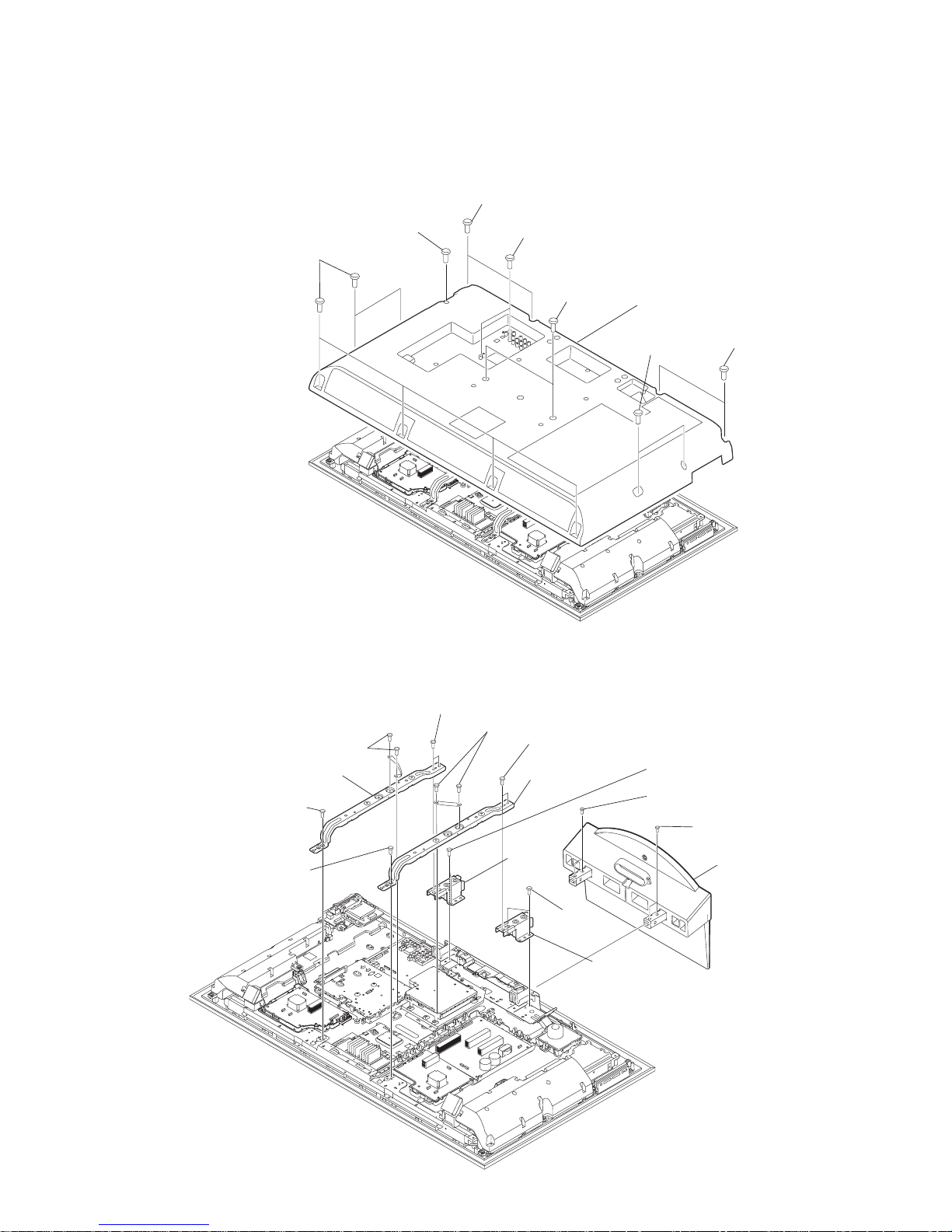
1-1. KLV-46X300A
1-1-1. REAR COVER ASSY REMOVAL
SECTION 1
DISASSEMBLY
1-1-2. STAND ASSY AND ARM ASSY REMOVAL
1 Two screws
(+BVTP2 4X16)
2 Two screws
(+PSW M5X12)
1 One screw
(+BVTP2 4X16)
1 Six screws
(+BVTP2 4X16)
3 Two screws
(+BV 3X12)
1 Two screws
(+BVTP2 4X16)
1 Two screws
(+BVTP2 4X16)
4 Rear cover assy
6 Two screws
(+BVST 3X8)
qa Two screws
(+BVST 4X8)
9 Two screws
(+BVST 4X8)
3 Two screws
(+BVST 3X8)
7 One screw
(+PSW M5X8)
7 Two screws
(+PSW M5X8)
4 Two screws
(+PSW M5X8)
4 One screw
(+PSW M5X8)
8 ARM L assy
5 ARM R assy
2 Base stand assy
1 Two screws
(+PSW 5X12)
1 Two screws
(+PSW 5X12)
0 Stand holder
qs Stand
holder
D846660B279CC0D5520DEF8E80C6FD0B0509C3DE5F2E1AA6843A75ED6228AB147AA810E8D0815DE5
KLV-46/52X300A, 46/52W380A (CH) 1-2
KLV-46X300A
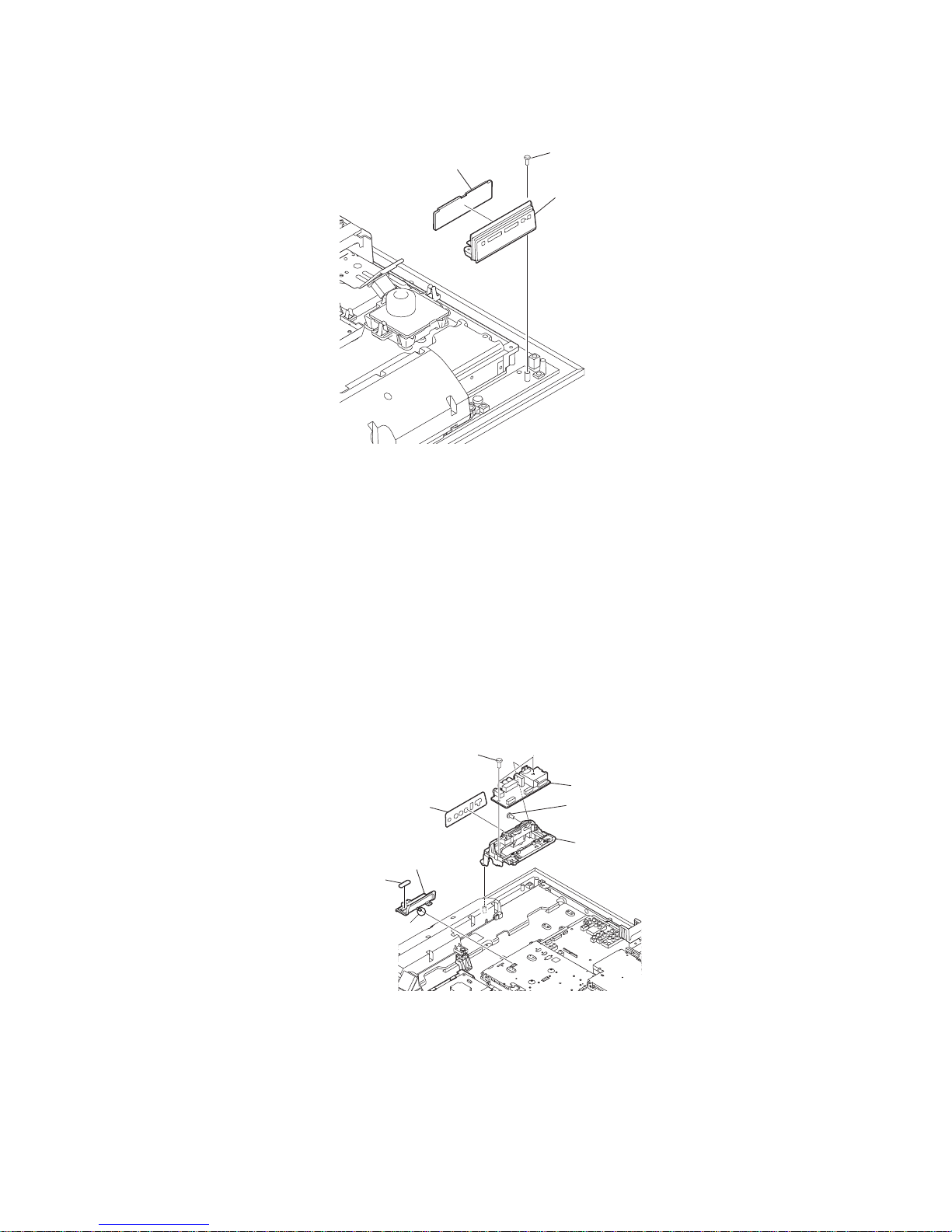
1-1-3. H1 BOARD REMOVAL
1-1-4. HW2 BOARD REMOVAL
2 Control button assy
3 H1 board
1 Two screws
(+BVTP2 4X16)
1 Two screws
(+BV 3X12)
4 Side terminal bracket
3 HW2 board
6 CARD bracket
2 One screw
(+PSW M3X5)
5 Side terminal label
7 MS cover
Claw
D846660B279CC0D5520DEF8E80C6FD0B0509C3DE5F2E1AA6843A75ED6228AB147AA810E8D0815DE5
KLV-46/52X300A, 46/52W380A (CH) 1-3
KLV-46X300A
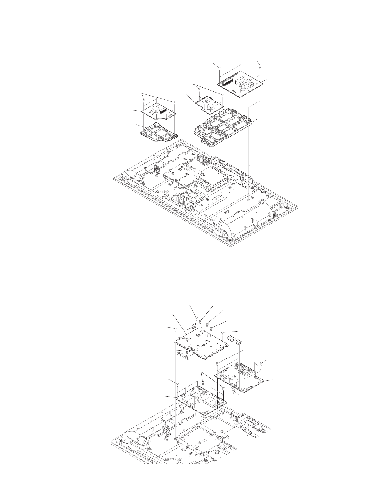
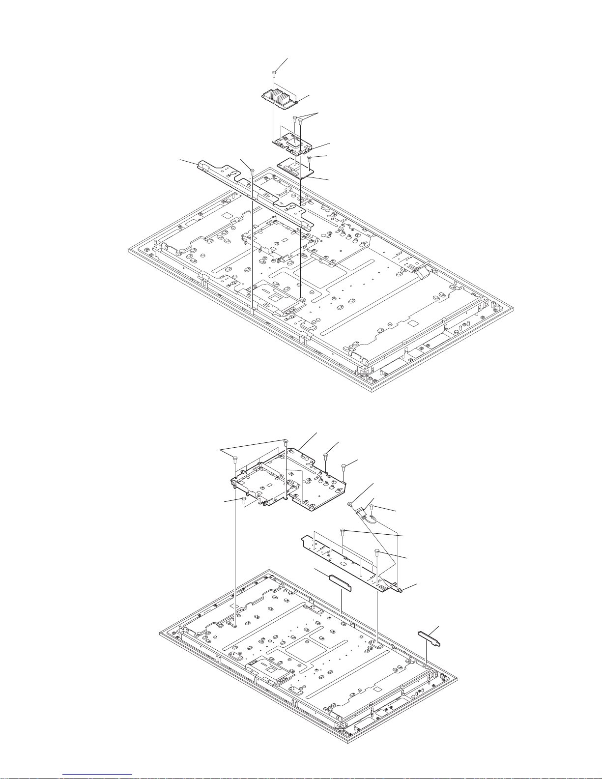
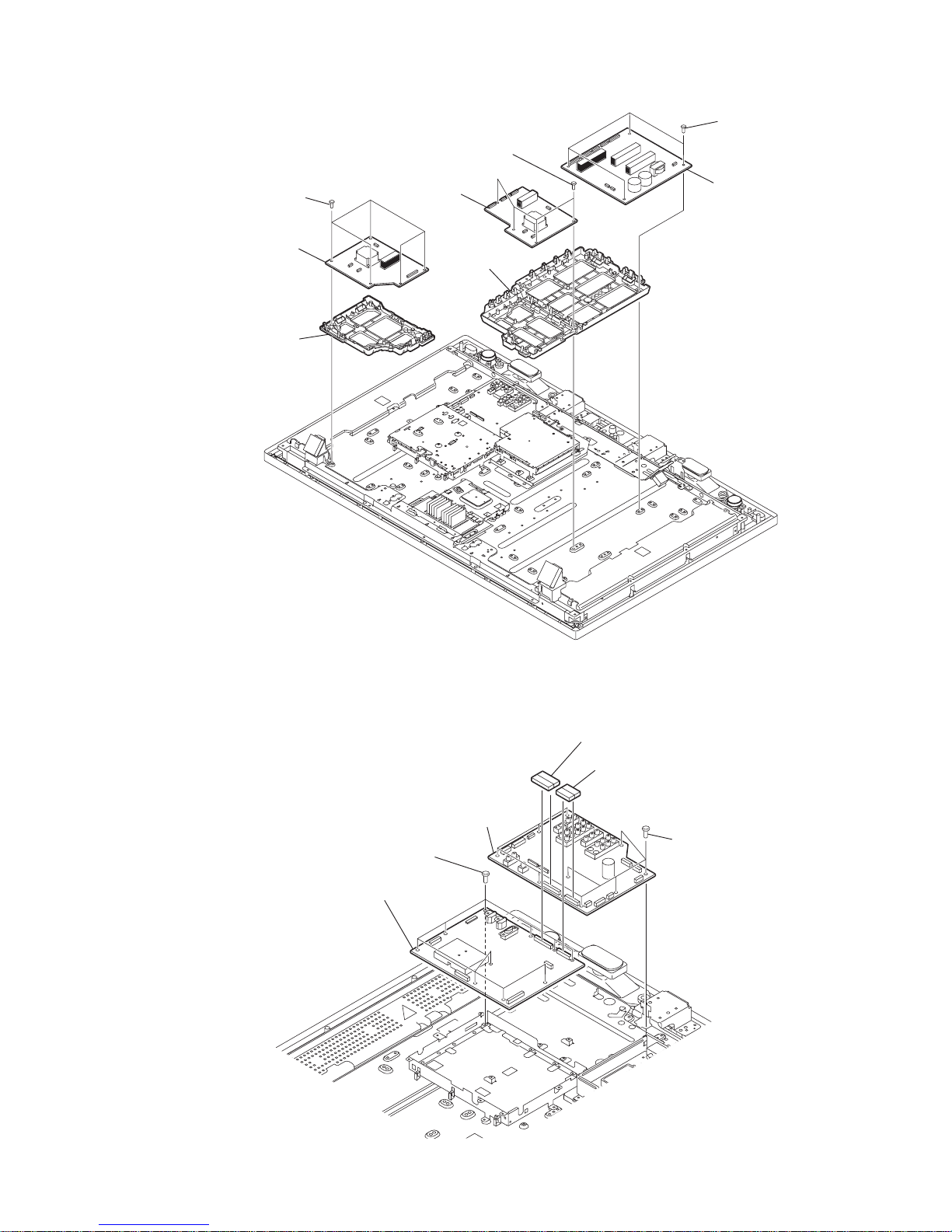
1-1-5. DF1 BOARD AND GF1 BOARD REMOVAL
1-1-6. AG BOARD AND FB2 BOARD REMOVAL
6 Two screws
(+PSW 3SG)
4 Four screws
(+PSW 3SG)
6 Two screws
(+PSW 3SG)
7 GF1 board
1 Five screws
(+PSW 3SG)
2 DF3 board
3 D3 bracket
5 DF2 board
8 GFD bracket
6 AG board
5 Four screws
(+BVST 3X8)
1 One screw
(+BVST 3X8)
1 One screw
(+BVST 3X8)
2 One screw
(+PSW M3X5)
3 Two screws
(HEX)
2 Two screws
(+PSW M3X5)
2 Two screws
(+PSW M3X5)
1 One screw
(+BVST 3X8)
4 FB top shield
5 Four screws
(+BVST 3X8)
7 Seven screws
(+BVST 3X8)
7 Three screws
(+BVST 3X8)
5 Two screws
(+BVST 3X8)
8 FB2 board
D846660B279CC0D5520DEF8E80C6FD0B0509C3DE5F2E1AA6843A75ED6228AB147AA810E8D0815DE5
KLV-46/52X300A, 46/52W380A (CH) 1-4
KLV-46X300A
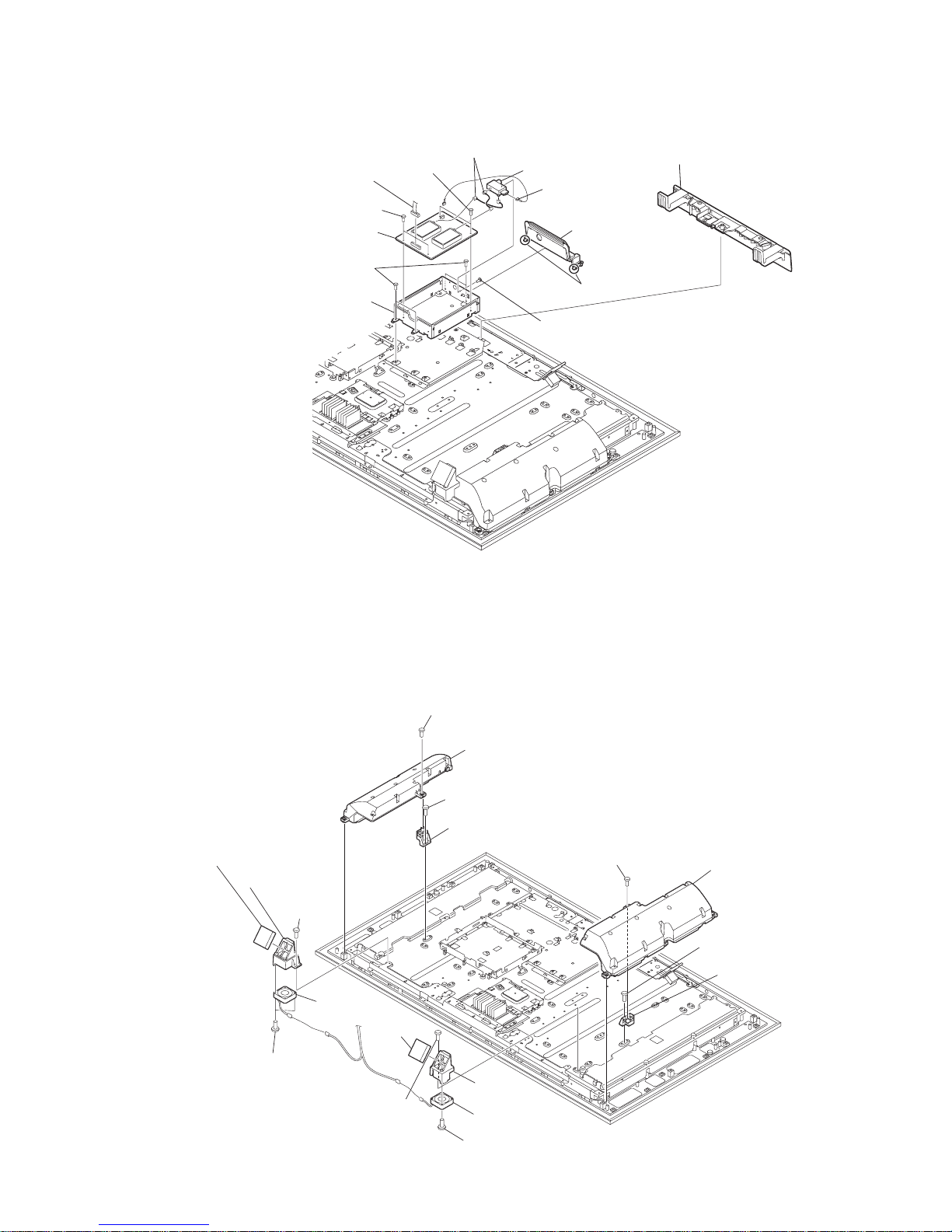
1-1-7. TUG BOARD REMOVAL
1-1-8. SPEAKER AND FAN REMOVAL
Under cover
0 Tuner shield (lower) assy
7 Two screws
(+BVST 3X8)
5 Connector assy
2 Screw
(+PSW M3X5)
3 Pin Cable
4 RF Splitter
6 Connector assy
1 TU bracket assy
Claws
7 Two screws
(+BVST 3X8)
8 TUG board
9 Four screws
(+BVST 3X8)
1 One screw
(+PWTP2 4X16)
4 SP holder
3 One screw
(+PSW M3X5)
2 loudspeaker(L)
8 SP holder(M)
6 loudspeaker(R)
qk D.C.fan
qj Two screws
(+BV 3X16)
qh Fan bracket
qk One screw
(+PSW 3X8)
qf Fan filter
qs Two screws
(+BV 3X16)
qd D.C.fan
0 One screw
(+PSW 3X8)
9 Fan filter
5 One screw
(+PWTP2 4X16)
7 One screw
(+PSW M3X5)
qa Fan bracket
D846660B279CC0D5520DEF8E80C6FD0B0509C3DE5F2E1AA6843A75ED6228AB147AA810E8D0815DE5
KLV-46/52X300A, 46/52W380A (CH) 1-5
KLV-46X300A
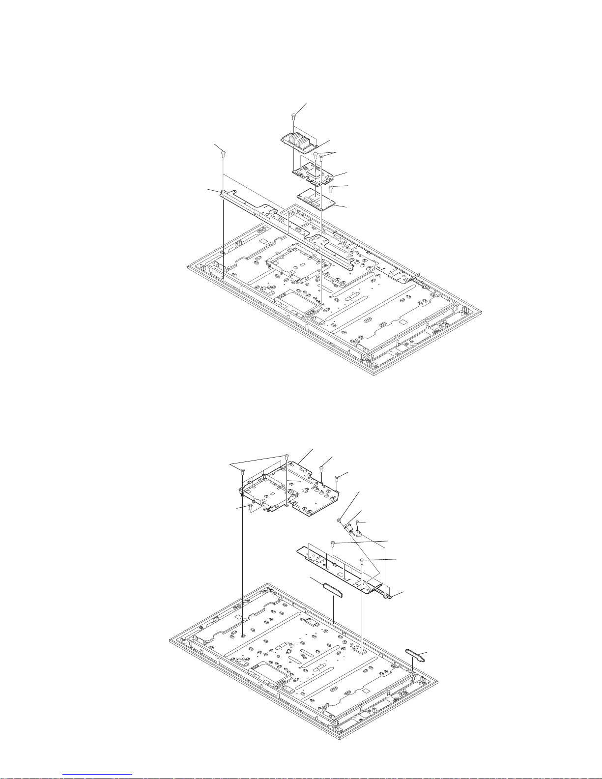
1-1-9. UB1 BOARD REMOVAL
1-1-10. H3 BOARD AND H4 BOARD AND AC INLET REMOVAL
1 Two screws
(+PSW M3X5)
8 Upper stay
6 UB1 board
4 UB1 shield
3 Three screws
(+PSW 3X8)
2 Fin assy
7 Three screws
(+BVTP2 4X16)
5 One screw
(+PSW M3X5)
2 Two screws
(+KTT 3X10)
9 One screw
(+PSW M3X5)
0 One screw
(+BVST 4X8)
9 Six screws
(+PSW M3X5)
8 H3 board
7 H4 board
6 Lower stay
1 One screw
(+PSW M4X6)
3 AC
inlet
9 One screw
(+PSW M3X5)
qa Chassis bracket
4 Four screws
(+PSW M5X8)
5 Three screws
(+BVTP2 4X16)
D846660B279CC0D5520DEF8E80C6FD0B0509C3DE5F2E1AA6843A75ED6228AB147AA810E8D0815DE5
KLV-46/52X300A, 46/52W380A (CH) 1-6
KLV-46X300A
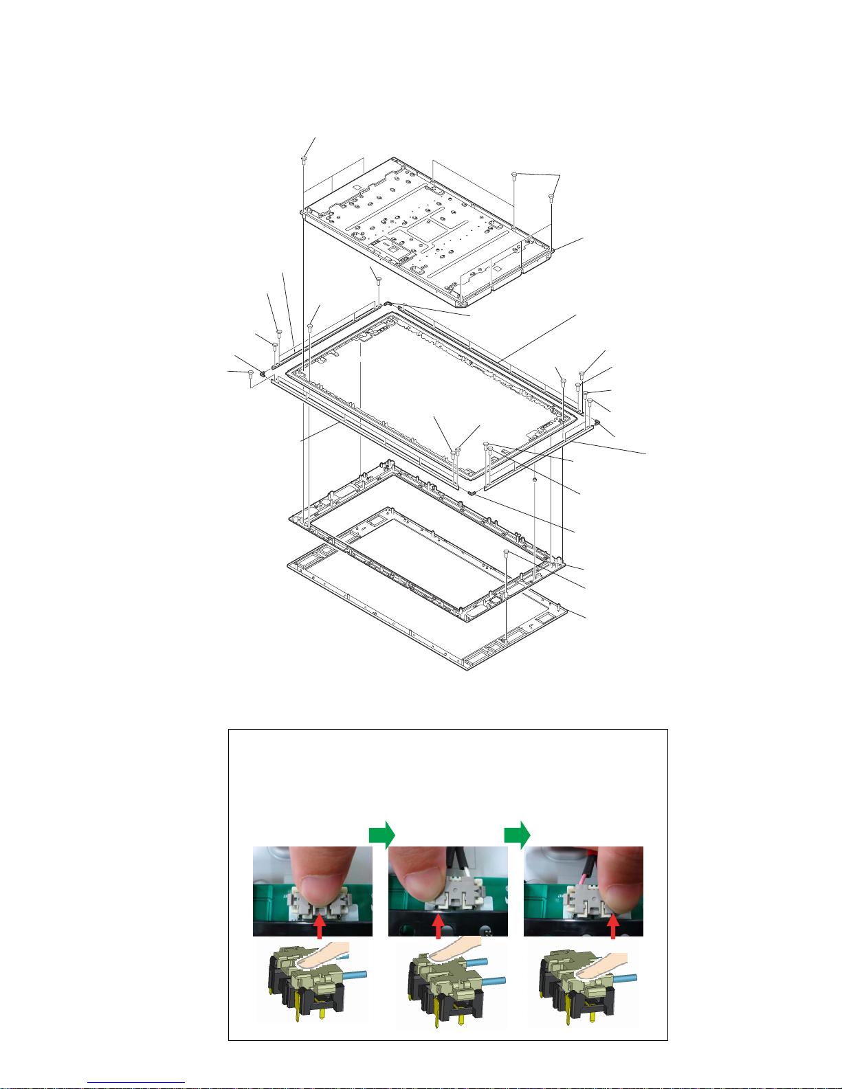
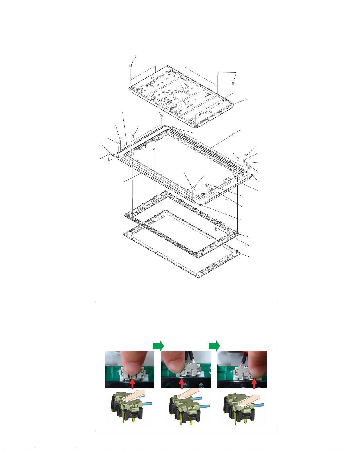
1-1-11. LCD PANEL AND FRONT CABINET ASSY REMOVAL
TO INSERT THE CONNECTOR
1 Press the middle
part of the connector
to insert till it locks.
The connector might not be properly locked when only pressed from the middle.
Be sure to press both sides to confirm it is property locked.
2 Press the right
side to confirm it is
locked.
3 Press the left
side to confirm it is
locked.
1 Six screws
(+BVTP2 4X16)
2 LCD panel
1 Three screws
(+BVTP2 4X16)
3 One screw
(+BV 3X12)
4 Center cabinet
5 One screw
(+BV 3X12)
6 Bezel assy
7 One screw
(M2 taping)
0 Ornametal joint
8 Two screws
(FIXED)
qa One screw
(M2 taping)
qs Six screws
(FIXED)
8 Two screws
(FIXED)
7 One screw
(M2 tapping)
9 Ornamental frame V
0 Ornametal joint
qk One screw
(M2 taping)
qg Foue screws
(FIXED)
qd Ornamental frame H
w; Ornamental frame H
qf One screw
(M2 taping)
qf One screw
(M2 taping)
3 One screw
(+BV 3X12)
qh Ornamental frame V
qj Ornamental joint
qj Ornamental joint
qk One screw
(M2 tapping)
ql Six screws
(FIX)
D846660B279CC0D5520DEF8E80C6FD0B0509C3DE5F2E1AA6843A75ED6228AB147AA810E8D0815DE5
KLV-46/52X300A, 46/52W380A (CH) 1-7
1 two screws
(+BVTP2 4X16)
2 two screws
(+PSW M5X12)
1 One screw
(+BVTP2 4X16)
1 Eight screws
(+BVTP2 4X16)
3 two screws
(+BV 3X12)
1 Five screws
(+BVTP2 4X16)
4 Rear cover assy
6 Two screws
(+BVST 3X8)
qa Two screws
(+BVST 4X8)
9 Two screws
(+BVST 4X8)
3 Two screws
(+BVST 3X8)
7 One screw
(+PSW M5X8)
7 Two screws
(+PSW M5X8)
4 Two screws
(+PSW M5X8)
4 One screw
(+PSW M5X8)
8 ARM L assy
5 ARM R assy
2 Base satnd assy
1 Two screws
(+PSW 5X12)
1 Two screws
(+PSW 5X12)
0 Stand holder
qs Stand
holder
1-2-2. STAND ASSY AND ARM ASSY REMOVAL
1-2. KLV-52X300A
1-2-1. REAR COVER ASSY REMOVAL
D846660B279CC0D5520DEF8E80C6FD0B0509C3DE5F2E1AA6843A75ED6228AB147AA810E8D0815DE5
KLV-46/52X300A, 46/52W380A (CH) 1-8
KLV-52X300A
1-2-3. H1 BOARD REMOVAL
1-2-4. HW2 BOARD REMOVAL
2 Control button assy
3 H1 board
1 One screw
(+BVTP2 4X16)
1 Two screws
(+BV 3X12)
4 Side terminal bracket
3 HW2 board
5 CARD bracket
2 One screw
(+PSW M3X5)
Claw

D846660B279CC0D5520DEF8E80C6FD0B0509C3DE5F2E1AA6843A75ED6228AB147AA810E8D0815DE5
KLV-46/52X300A, 46/52W380A (CH) 1-9
6 Two screws
(+PSW 3SG)
4 Two screws
(+PSW 3SG)
6 Two screws
(+PSW 3SG)
7 GF2 board
1 Five screws
(+PSW 3SG)
2 DF5 board
3 D3 bracket
5 DF4 board
8 GFD bracket
4 Two screws
(+PSW 3SG)
6 AG board
5 Four screws
(+BVST 3X8)
1 One screw
(+BVST 3X8)
1 One screw
(+BVST 3X8)
2 One screw
(+PSW M3X5)
3 Two screws
(HEX)
2 Two screws
(+PSW M3X5)
2 Two screws
(+PSW M3X5)
1 One screw
(+BVST 3X8)
4 FB top shield
5 Four screws
(+BVST 3X8)
7 Seven screws
(+BVST 3X8)
7 Three screws
(+BVST 3X8)
5 Two screws
(+BVST 3X8)
8 FB2 board
1-2-6. AG AND FB2 BOARDS REMOVAL
KLV-52X300A
1-2-5. DF2, DF3 AND GF1 BOARDS REMOVAL
D846660B279CC0D5520DEF8E80C6FD0B0509C3DE5F2E1AA6843A75ED6228AB147AA810E8D0815DE5
KLV-46/52X300A, 46/52W380A (CH) 1-10
KLV-52X300A
1-2-7. TUG BOARD REMOVAL
1-2-8. SPEAKER AND FAN REMOVAL
Under cover
0 Tuner shield (lower) assy
7 Two screws
(+BVST 3X8)
5 Connector assy
2 Screw
(+PSW M3X5)
3 Pin Cable
4 RF Splitter
6 Connector assy
1 TU bracket assy
Claws
7 Two screws
(+BVST 3X8)
8 TUG board
9 Four screws
(+BVST 3X8)
1 One screw
(+PWTP2 4X16)
4 SP holder
3 One screw
(+PSW M3X5)
2 Loudspeaker(L)
8 SP holder (M)
6 Loudspeaker(R)
5 One screw
(+PWTP2 4X16)
7 One screw
(+PSW M3X5)
D846660B279CC0D5520DEF8E80C6FD0B0509C3DE5F2E1AA6843A75ED6228AB147AA810E8D0815DE5
KLV-46/52X300A, 46/52W380A (CH) 1-11
KLV-52X300A
1-2-9. UB1 BOARD REMOVAL
1 Two screws
(+PSW M3X5)
8 Upper stay
6 UB1 board
4 UB1 shield
3 Three screws
(+PSW 3X8)
2 Fin assy
7 Three screws
(+BVTP2 4X16)
5 One screw
(+PSW M3X5)
2 Two screws
(+KTT 3X10)
9 One screw
(+PSW M3X5)
0 One screw
(+BVST 4X8)
9 Six screws
(+PSW M3X5)
8 H3 board
7 H4 board
6 Lower stay
1 One screw
(+PSW M4X6)
3 AC inlet
9 One screw
(+PSW M3X5)
qa Chassis bracket
4 Four screws
(+PSW M5X8)
5 Two screws
(+BVTP2 4X16)
1-2-10. H3 BOARD AND H4 BOARD AND AC INLET REMOVAL
D846660B279CC0D5520DEF8E80C6FD0B0509C3DE5F2E1AA6843A75ED6228AB147AA810E8D0815DE5
KLV-46/52X300A, 46/52W380A (CH) 1-12
KLV-52X300A
1-2-11. LCD PANEL AND FRONT CABINET ASSY REMOVAL
TO INSERT THE CONNECTOR
1 Press the middle
part of the connector
to insert till it locks.
The connector might not be properly locked when only pressed from the middle.
Be sure to press both sides to confirm it is property locked.
2 Press the right
side to confirm it is
locked.
3 Press the left
side to confirm it is
locked.
1 Six screws
(+BVTP2 4X16)
2 LCD panel
1 Tree screws
(+BVTP2 4X16)
3 One screw
(+BV 3X12)
4 Center cabinet
5 One screw
(+PSW M3X12)
6 bezel assy
7 One screw
(M2 tapping)
0 Ornametal joint
8 Two screws
(FIXED)
qa One screw
(M2 taping)
qs Six screw
(FIXED)
8 Two screws
(FIX)
7 One screw
(M2 taping)
9 Ornamental frame V
0 Ornamental joint
qk One screw
(M2 taping)
qg Four screws
(FIXED)
qd Ornamental frame H
w; Ornamental
frame H
qf One screw
(M2 taping)
qf One screw
(M2 taping)
3 One screw
(+BV 3X12)
qh Ornamental
frame V
qj Ornamental
joint
qj Ornamental joint
qk One screw
(M2 taping)
ql Six screw
(FIXED)
D846660B279CC0D5520DEF8E80C6FD0B0509C3DE5F2E1AA6843A75ED6228AB147AA810E8D0815DE5
KLV-46/52X300A, 46/52W380A (CH) 1-13
1-3. KLV-46W380A
1-3-1. REAR COVER ASSY REMOVAL
1-3-2. STAND ASSY AND ARM ASSY REMOVAL
2 Two screws
(+PSW M5X12)
3 Two screws
(+BV 3X12)
1 Six screws
(+BVTP2 4X16)
1 Four screws
(+BVTP2 4X16)
1 Four screws
(+BVTP2 4X16)
1 Five screws
(+BVTP2 4X16)
4 Rear cover assy
qa Two screws
(+BVST 4X8)
9 Two screws
(+BVST 4X8)
1 Two screws
(+PSW M5X12)
1 Two screws
(+PSW M5X12)
2 Stand (L)assy
0 Stand holder
qs Stand holder
6 Two screws
(+BVST 3X8)
3 Two screws
(+BVST 3X8)
7 Three screws
(+PSW M5X8)
4 Three screws
(+PSW M5X8)
8 Arm L ASSY
5 Arm R ASSY
D846660B279CC0D5520DEF8E80C6FD0B0509C3DE5F2E1AA6843A75ED6228AB147AA810E8D0815DE5
KLV-46/52X300A, 46/52W380A (CH) 1-14
KLV-46W380A
1-3-3. HW1 BOARD REMOVAL
1-3-4. HW2 BOARD REMOVAL
1 Button cover
2 Multi button assy
3 HW1 board
4 Two screws
(+BVST 3X8)
1 Two screws
(+BV 3X12)
5 Side terminal bracket
3 HW2 board
2 One screw
(+PSW M3X5)
D846660B279CC0D5520DEF8E80C6FD0B0509C3DE5F2E1AA6843A75ED6228AB147AA810E8D0815DE5
KLV-46/52X300A, 46/52W380A (CH) 1-15
KLV-46W380A
1-3-5. DF2, DF3 AND GF1 BOARDS REMOVAL
1-3-6. AG AND FB2 BOARDS REMOVAL
1 Five screws
(+PSW 3SG)
5 DF2 board
7 GF1 board
8 GFD bracket
2 DF3 board
3 DF3 bracket
4 Four screws
(+PSW 3SG)
6 Four screws
(+PSW 3SG)
4 FB2 board
6 AG board
1 Board to board connector 80P
2 Board to board connector 50P
3 Ten screws
(+PSW M3X5)
5 Nine screws
(+PSW M3X5)
D846660B279CC0D5520DEF8E80C6FD0B0509C3DE5F2E1AA6843A75ED6228AB147AA810E8D0815DE5
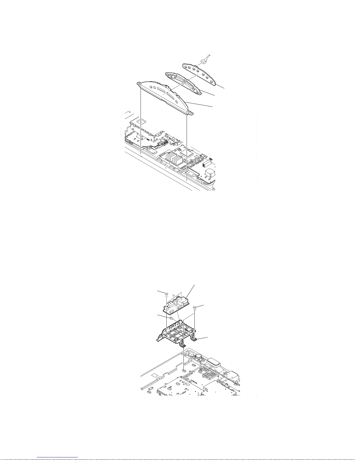
KLV-46/52X300A, 46/52W380A (CH) 1-16
KLV-46W380A
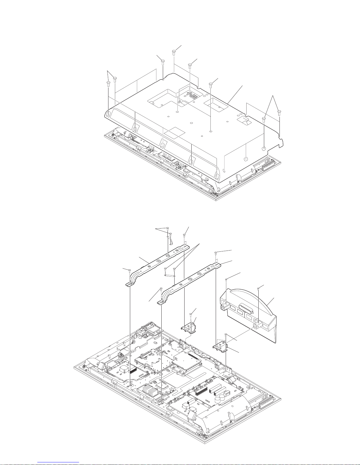
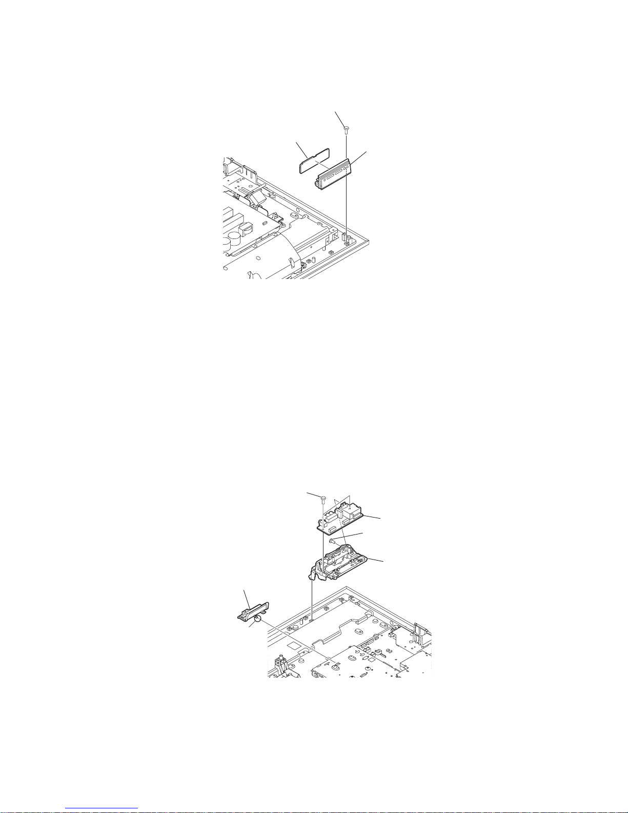
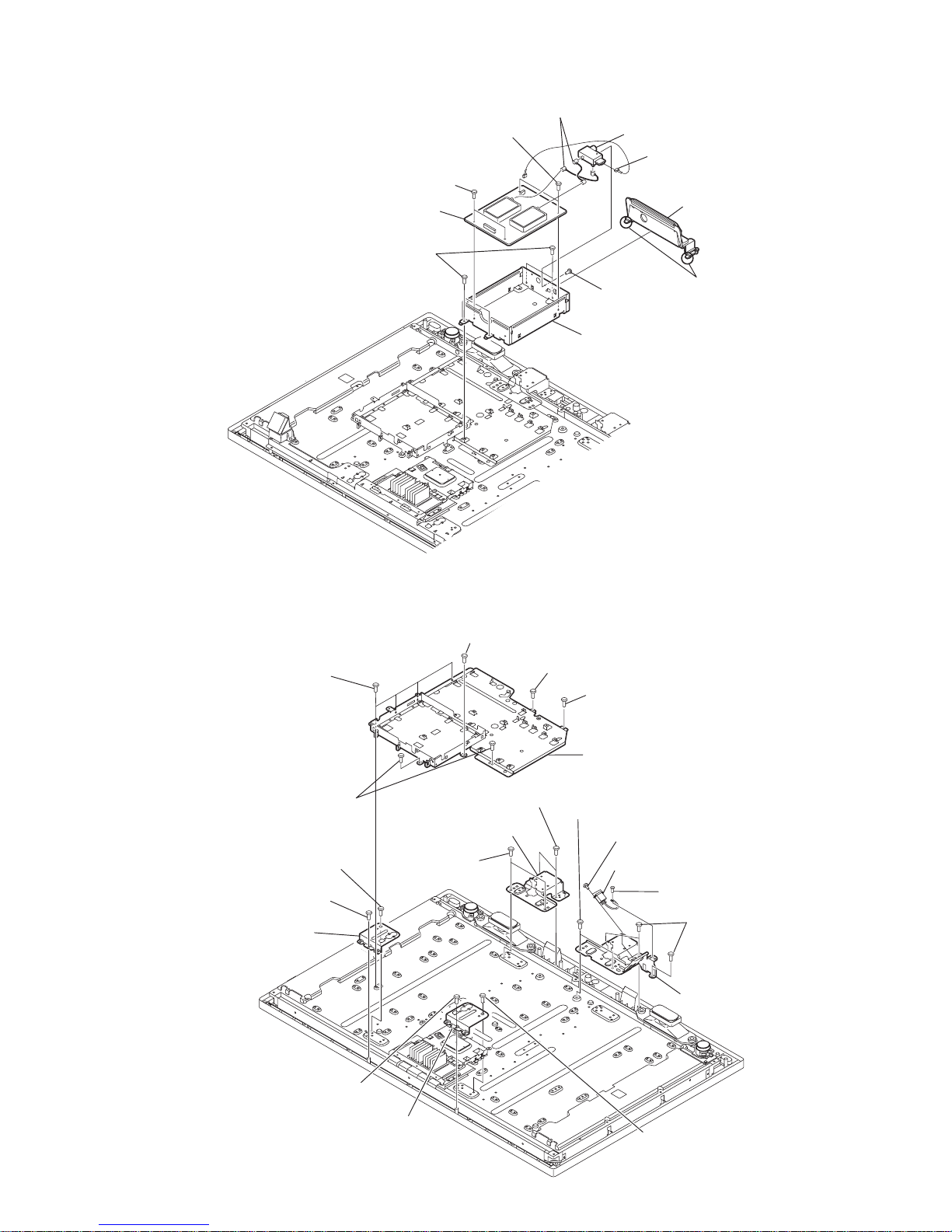
1-3-7. TUG BOARD REMOVAL
1-3-8. CHASSIS BRACKET AND STAY REMOVAL
9 Tuner shield (lower) assy
6 Two screws
(+BVST 3X8)
5 Connector assy
2 One Screw
(+PSW M3X5)
3 Pin Cable
4 RF Splitter
1 TU bracket assy
Claws
6 Two screws
(+BBVST 3X8)
7 TUG board
8 Four screws
(+BVST 3X8)
qa Two screws
(+KTT 3X10)
0 One screw
(+PSW M4X6)
qf Three screws
( +BVTP2 4X16)
qg Stay lower R
6 Stay upper R
3 Stay upper L
9 Stay lower L
8 Two screws
( +BVTP2 4X16)
4 One screw
( +BVTP2 4X16)
2 One screw
( +BVTP2 4X16)
qd Two screws
(+PSW M5X8)
7 Two screws
(+PSW M5X8)
5 One screw
(+PSW M5X8)
1 One screw
(+PSW M5X8)
qs AC inlet
qh Four screws
(+PSW M3X5)
qh Two screws
(+PSW M3X5)
qh One screw
(+PSW M3X5)
qh One screws
(+PSW M3X5)
qj One screw
( +BVST 4X8)
qk Chassis bracket
D846660B279CC0D5520DEF8E80C6FD0B0509C3DE5F2E1AA6843A75ED6228AB147AA810E8D0815DE5
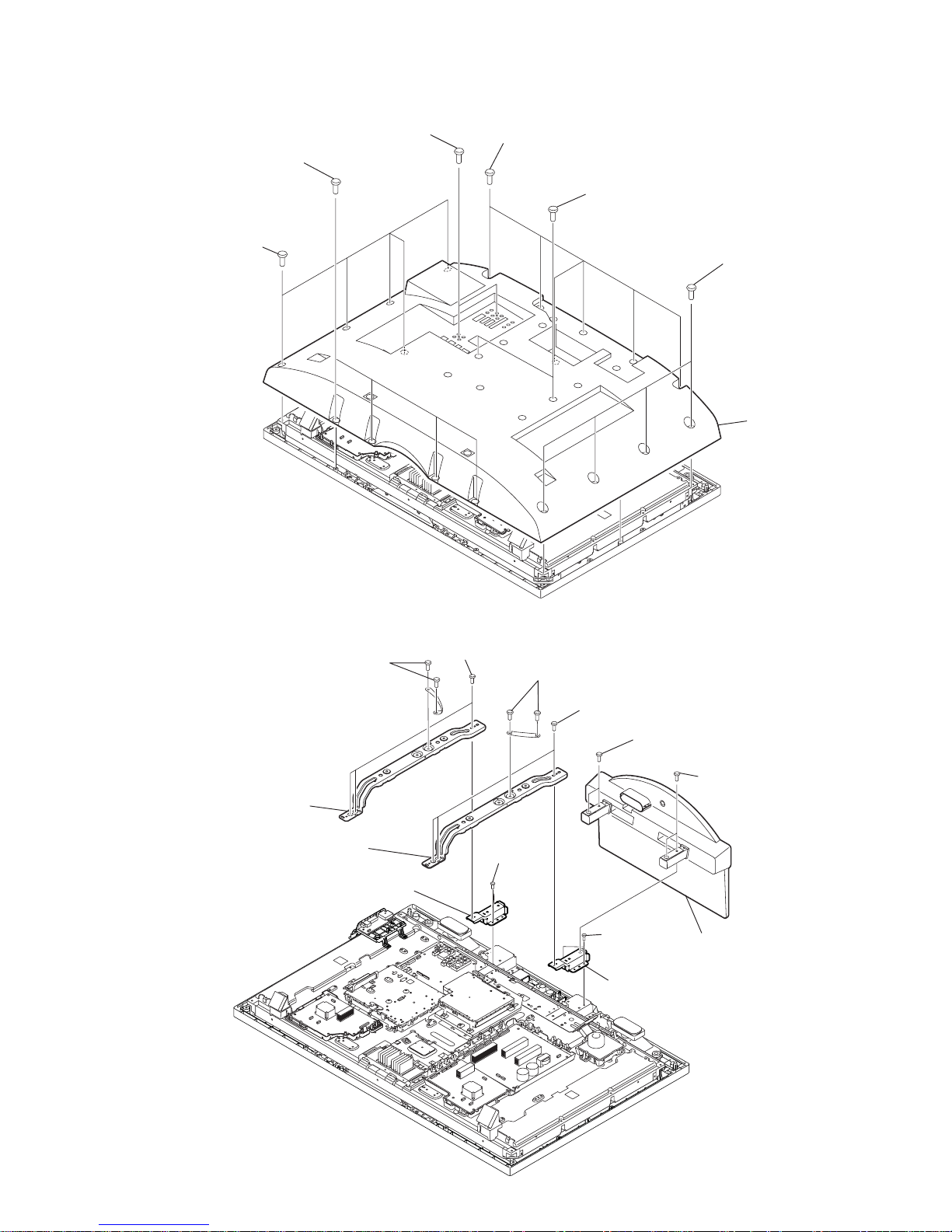
KLV-46/52X300A, 46/52W380A (CH) 1-17
KLV-46W380A
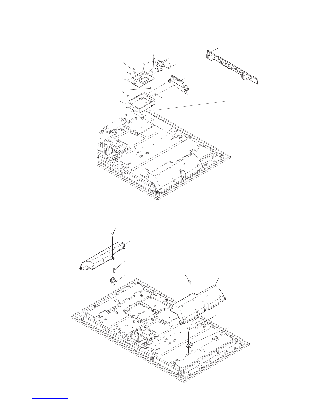
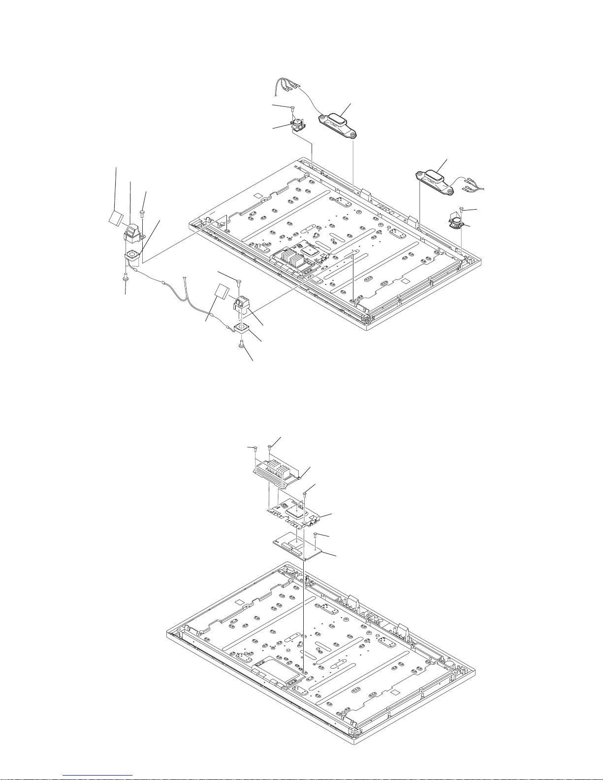
1-3-9. FAN AND SPEAKER REMOVAL
1-3-10. UB2 BOARD REMOVAL
2 Three screws
(+BVTP2 4X16)
3 Loud Speaker
(Tweeter)
1 Loudspeaker
5 Three screws
(+BVTP2 4X16)
6 Loud Speaker
(Tweeter)
4 Loudspeaker
qh D.C. fan
qg Two screws
(+BV 3X16)
qf Fan bracket
qs Fan filter
qd One screw
(+PSW 3X8)
q; Two screws
(+BV 3X16)
qa D.C. fan
8 One screw (+PSW 3X8)
7 Fan filter
9 Fan bracket
1 Two screws
(+PSW M3X5)
6 UB2 board
4 UB1 shield
3 Four screws
(+PSW 3X8)
2 Fin assy
5 One screw
(+PSW M3X5)
1 Two screws
(+BVTP2 4X16)
 Loading...