

Sony KLV-40V440A, KLV-46V440A, KLV-52V440A Service Manual
D846660B279CC0D5520DEF8E80C6FD0B0509C3DE5F2E1AA6282FE9404AF74314F140FE080ED95A15
SERVICE MANUAL
LCD Colour TV
China Model
EX1 CHASSIS
KLV-40V440A/46V440A/52V440A
RM-SA014 KLV-40V440A/46V440A/52V440A
D846660B279CC0D5520DEF8E80C6FD0B0509C3DE5F2E1AA6282FE9404AF74314F140FE080ED95A15
KLV-40/46/52V440A (CH) 2
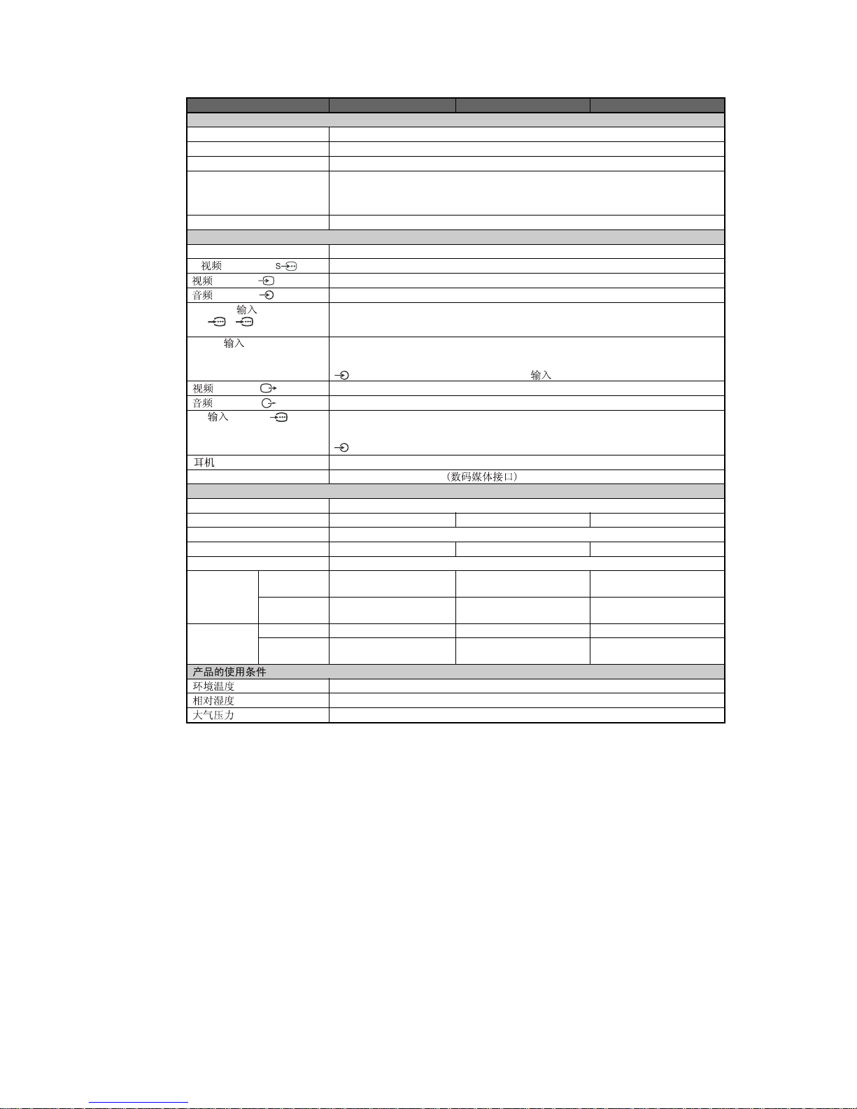
SPECIFICATIONS
Panel System
TV System
Colour System
Channel Coverage
Sound Output
Input/Output jacks
Antenna
S (S VIDEO) 1
(VIDEO) 1, 2, 3
(AUDIO) 1, 2, 3
HD/DVD (HD/DVD
In) 1/ 2
HDMI (HDMI IN) 1, 2, 3
(VIDEO)
(AUDIO)
PC (PC IN) (RGB)
(Headphone)
DMPORT
Power and others
Power Requirements
Screen Size
Display Resolution
Power Consumption
Standby Power Consumption*
Dimensions** with stand
(w × h × d) (mm)
without stand
(mm)
Mass** with stand (kg)
without stand
(kg)
LCD (Liquid Crystal Display) Panel
B/G, I, D/K, M
PAL, PAL60, SECAM, NTSC 3.58, NTSC 4.43 (only Video In)
B/G: VHF: E2 to E12/ UHF: E21 to E69/ CATV: S01 to S03, S1 to S41
I: UHF: B21 to B69/ CATV: S01 to S03, S1 to S41
D/K: VHF:
C1 to C12, R1 to R12/ UHF: C13 to C57, R21 to R60/ CATV: S01 to S03, S1 to S41, Z1 to Z39
M: VHF: A2 to A13/ UHF: A14 to A79/ CATV: A-8 to A-2, A to W+4, W+6 to W+84
10 W + 10 W
75 ohm external terminal for VHF/UHF
S video input (4-pin mini DIN)
Video input (phono jack)
Audio input (phono jacks): 500 mVrms, Impedance: 47 kilohms
Supported formats: 1080p, 1080i, 720p, 576p, 576i, 480p, 480i
Y: 1 Vp-p, 75 ohms, 0.3V negative sync/P
B/CB
: 0.7 Vp-p, 75 ohms/
PR/CR: 0.7 Vp-p, 75 ohms
Video: 1080/24p, 1080p, 1080i, 720p, 576p, 576i, 480p, 480i
Audio: Two channel linear PCM
32, 44.1 and 48 kHz, 16, 20 and 24 bits
Analogue audio input (minijack) (HDMI (HDMI IN) 3 only)
Video output (phono jack)
Audio output (phono jacks)
PC Input (D-sub 15-pin)
G: 0.7 Vp-p, 75 ohms, non Sync on Green/B: 0.7 Vp-p, 75 ohms/
R: 0.7 Vp-p, 75 ohms/HD: 1-5 Vp-p/VD: 1-5 Vp-p
PC audio input (minijack)
Headphones jack
DIGITAL MEDIA PORT
220 V AC, 50 Hz
132 cm (52 inches) 117 cm (46 inches) 102 cm (40 inches)
1,920 dots (horizontal) × 1,080 lines (vertical)
280 W 270 W 220 W
0.3 W
1,262 × 871 × 347 1,120 × 782 × 307 986 × 684 × 279
1,262 × 829 × 119 1,120 × 742 × 115 986 × 646 × 110
39 30 23
33 26 19
5°C - 35°C
20% - 80%
86 kPa - 106 kPa
Model name KLV-52V440A KLV-46V440A KLV-40V440A
System
* Specified standby power is reached after the TV finishes necessary internal processes.
** The values of dimensions and mass are approximate.
D846660B279CC0D5520DEF8E80C6FD0B0509C3DE5F2E1AA6282FE9404AF74314F140FE080ED95A15
KLV-40/46/52V440A (CH) 3
Design and specifications are subject to change without notice.
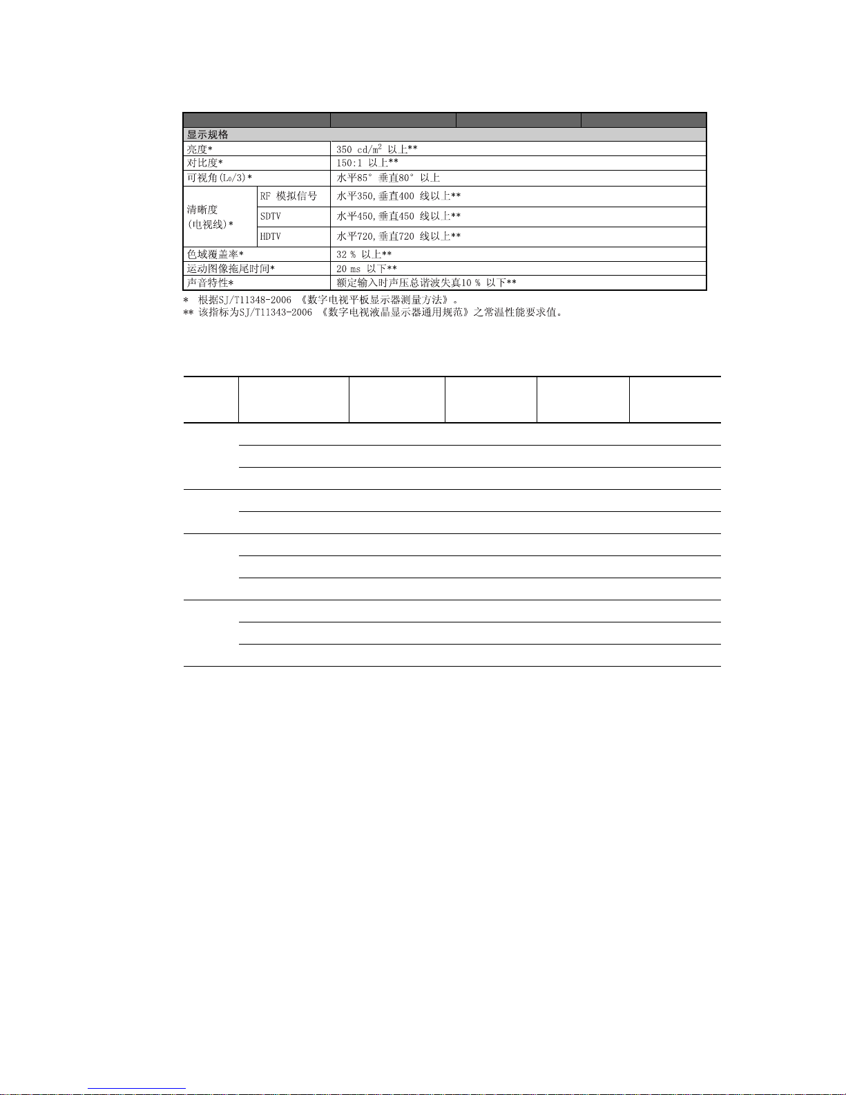
PC Input Signal Reference Chart
Model name KLV-52V440A KLV-46V440A KLV-40V440A
Signals Horizontal (Pixel) Vertical (Line) Standard
Horizontal
frequency
(kHz)
Vertical
frequency (Hz)
VGA 640 480 31.5 60 VGA
640 480 37.5 75 VESA
720 400 31.5 70 VGA-T
SVGA 800 600 37.9 60 VESA Guidelines
800 600 46.9 75 VESA
XGA 1024 768 48.4 60 VESA Guidelines
1024 768 56.5 70 VESA
1024 768 60 75 VESA
WXGA 1280 768 47.4 60 VESA
1280 768 47.8 60 VESA
1360 768 47.7 60 VESA
• This TV’s PC input does not support Sync on Green or Composite Sync.
• This TV’s PC input does not support interlaced signals.
• If input signal is not shown in above chart, then this signal may not be displayed properly or cannot be displayed according to
your settings.
• For the best picture quality, it is recommended to use the signals (boldfaced) in the above chart with a 60 Hz vertical frequency
from a personal computer. In plug and play, signals with a 60 Hz vertical frequency will be selected automatically.

D846660B279CC0D5520DEF8E80C6FD0B0509C3DE5F2E1AA6282FE9404AF74314F140FE080ED95A15
KLV-40/46/52V440A (CH) 4
CAUTION
These servicing instructions are for use by qualified service
personnel only.
To reduce the risk of electric shock, do not perform any servicing
other than that contained in the operating instructions unless you
are qualified to do so.
WARNING!!
An isolation transformer should be used during any service to
avoid possible shock hazard, because of live chassis.
The chassis of this receiver is directly connected to the ac power
line.
! SAFETY-RELATED COMPONENT
WARNING!!
Replace all components with Sony parts whose part numbers
appear as shown in this manual or in supplements
published by Sony.
WARNINGS AND CAUTIONS SAFETY-RELATED COMPONENT
WARNING
It is essential that all critical parts be replaced only with the part
number specified in the electrical parts list to prevent electric
shock, fire, or other hazard.
NOTE: Do not modify the original design without obtaining
written permission from the manufacturer or you will
void the original parts and labor guarantee.
USE CAUTION WHEN HANDLING THE LCD PANEL
When repairing the LCD panel, be sure you are grounded by
using a wrist band.
When repairing the LCD panel on the wall, the LCD panel must
be secured using the 4 mounting holes on the rear cover.
1) Do not press on the panel or frame edge to avoid the risk of
electric shock.
2) Do not scratch or press on the panel with any sharp objects.
3) Do not leave the module in high temperatures or in areas of
high humidity for an extended period of time.
4) Do not expose the LCD panel to direct sunlight.
5) Avoid contact with water. It may cause a short circuit within
the module.
6) Disconnect the AC power when replacing the backlight (CCFL)
or inverter circuit.
(High voltage occurs at the inverter circuit at 650Vrms.)
7) Always clean the LCD panel with a soft cloth material.
8) Use care when handling the wires or connectors of the inverter
circuit. Damaging the wires may cause a short.
9) Protect the panel from ESD to avoid damaging the electronic
circuit (C-MOS).
D846660B279CC0D5520DEF8E80C6FD0B0509C3DE5F2E1AA6282FE9404AF74314F140FE080ED95A15
KLV-40/46/52V440A (CH) 5
SAFETY CHECK-OUT
After correcting the original service problem, perform the
following safety checks before releasing the set to the customer:
1. Check the area of your repair for unsoldered or poorly
soldered connections. Check the entire board surface for
solder splashes and bridges.
2. Check the interboard wiring to ensure that no wires are
“pinched” or touching high-wattage resistors.
3. Check that all control knobs, shields, covers, ground straps,
and mounting hardware have been replaced. Be absolutely
certain that you have replaced all the insulators.
4. Look for unauthorized replacement parts, particularly
transistors, that were installed during a previous repair. Point
them out to the customer and recommend their replacement.
5. Look for parts which, though functioning, show obvious
signs of deterioration. Point them out to the customer and
recommend their replacement.
6. Check the line cords for cracks and abrasion. Recommend
the replacement of any such line cord to the customer.
7. Check the antenna terminals, metal trim, “metallized”
knobs, screws, and all other exposed metal parts for AC
leakage. Check leakage as described below.
Leakage Test
The AC leakage from any exposed metal part to earth ground
and from all exposed metal parts to any exposed metal part
having a return to chassis, must not exceed 0.5 mA (500
microamperes).
Leakage current can be measured by any one of three methods.
1. A commercial leakage tester, such as the Simpson 229 or
RCA WT-540A. Follow the manufacturers’ instructions to
use these instructions.
2. A battery-operated AC milliampmeter. The Data Precision
245 digital multimeter is suitable for this job.
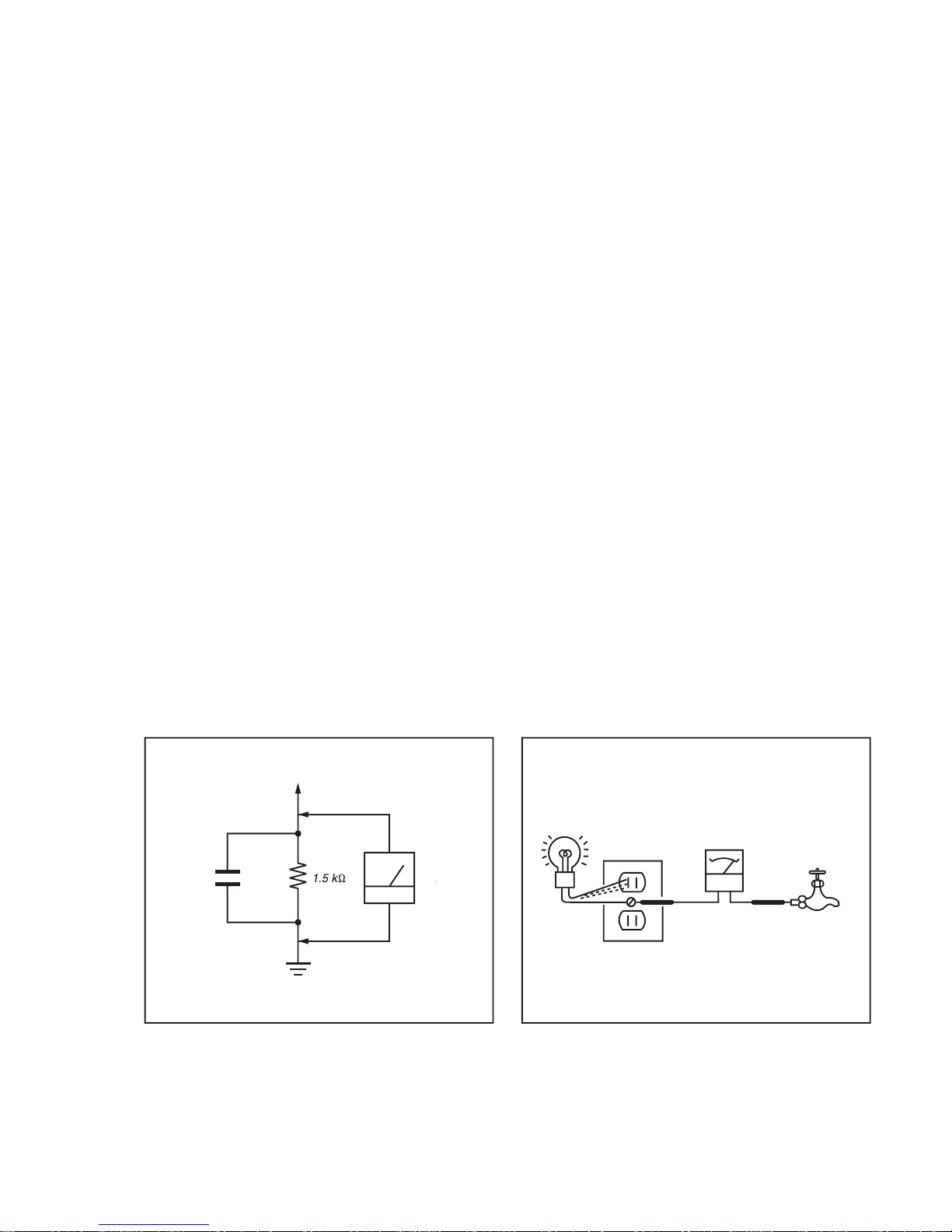
3. Measuring the voltage drop across a resistor by means of a
VOM or battery-operated AC voltmeter. The “limit”
indication is 0.75 V, so analog meters must have an accurate
low voltage scale.
The Simpson’s 250 and Sanwa SH-63TRD are examples of
passive VOMs that are suitable. Nearly all battery-operated
digital multimeters that have a 2 VAC range are suitable (see
Figure A).
How to Find a Good Earth Ground
A cold-water pipe is a guaranteed earth ground; the cover-plate
retaining screw on most AC outlet boxes is also at earth ground.
If the retaining screw is to be used as your earth ground, verify
that it is at ground by measuring the resistance between it and a
cold-water pipe with an ohmmeter. The reading should be zero
ohms.
If a cold-water pipe is not accessible, connect a 60- to 100-watt
trouble- light (not a neon lamp) between the hot side of the
receptacle and the retaining screw. Try both slots, if necessary,
to locate the hot side on the line; the lamp should light at normal
brilliance if the screw is at ground potential (see Figure B).
Exposed Meta
l
Parts on Se
t
.15
µ
Earth Groun
d
AC
0.75V
)
ouble Ligh
t
AC Outlet Box
Ohmmeter
Col
d-water Pi
pe
FigureA. Using an AC voltmeter to check AC leakage. Figure B. Checking for earth ground
.
D846660B279CC0D5520DEF8E80C6FD0B0509C3DE5F2E1AA6282FE9404AF74314F140FE080ED95A15
KLV-40/46/52V440A (CH) 6
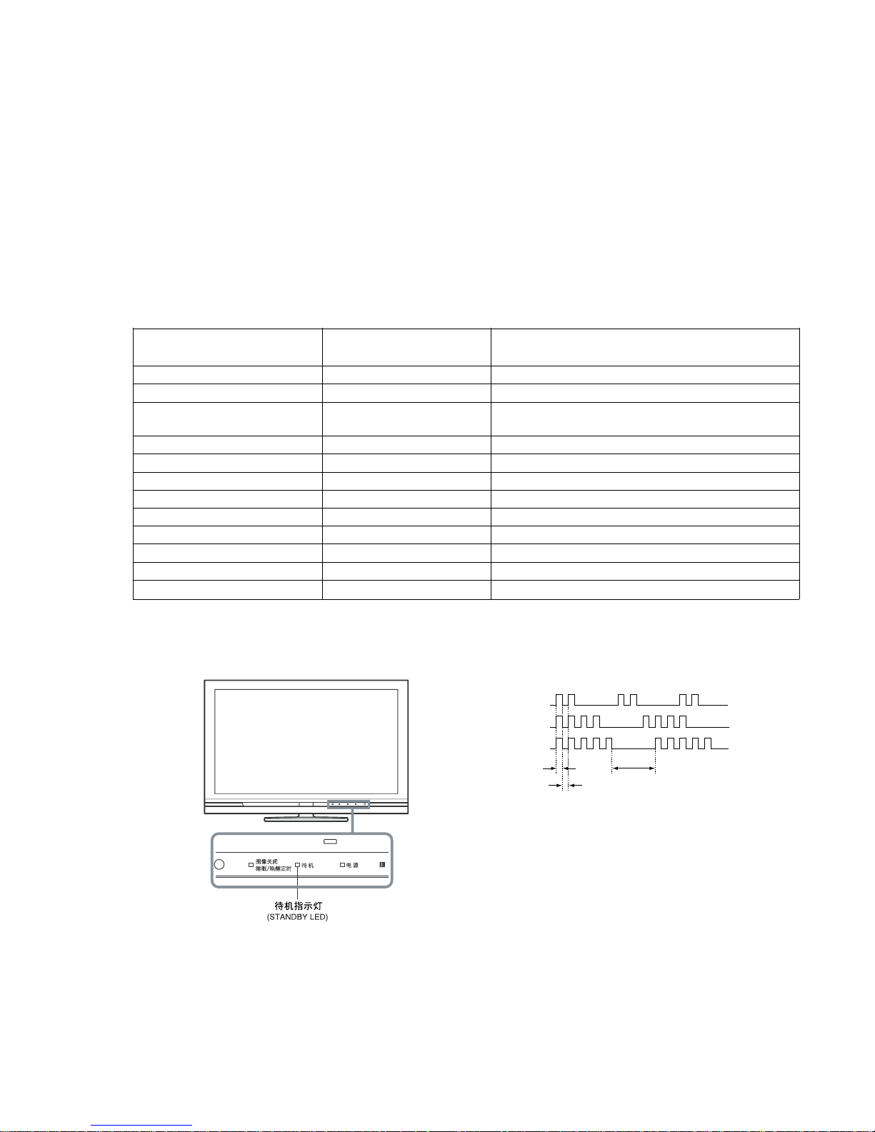
SELF DIAGNOSIS FUNCTION
The units in this manual contain a self-diagnostic function. If an error occurs, the STANDBY LED will automatically begin to flash.
The number of times the LED flashes translates to a probable source of the problem.
A definition of the STANDBY LED flash indicators is listed in the instruction manual for the user’s knowledge and reference.
If an error symptom cannot be reproduced, the remote commander can be used to review the failure occurrence data stored in memory to
reveal past problems and how often these problems occur.
1-1. DIAGNOSTIC TEST INDICATORS
When an error occurs, the STANDBY LED will flash a set number of times to indicate the possible cause of the problem.
If there is more than one error, the LED will identify the first of the problem areas.
Result for all of the following diagnostic items are displayed on screen.
If the screen displays a “0”, no error has occurred .
Number of times STANDY LED Monitoring Items
Diagnostic Item Description
(Red) flashes (Screen Display)
2 times DC_DET Main power supply voltage error (12V, etc)
3 times DC_ALERT1 Malfunction of 3.3V line (Trident circuit, etc)
4 times DC_ALERT2 Malfunction of 5V line
(Voltage Supply to FE, etc)
5 times DC_ALERT3 Malfunction of power supply for screen
6 times BACKLIGHT Malfunction of inverter or overcurrent, etc
7 times TEMPERATURE Abnormal temperature inside unit
8 times AUDIO Audio circuit error (amplifier, etc.)
9 times AUSD FAN Fan malfunction
10 times DEF Digital FE circuit error
11 times B-ENGINE Malfunction of Trident IC or around IC
12 times HFR BH board error
13 times (No item on screen display) Malfunction of balancer
1-2. DISPLAY OF STANDBY/TIMER LIGHT FLASH COUNT
1-3. STOPPING THE STANDBY FLASH
Turn off the power switch on the TV main unit or unplug the power cord from the outlet to stop the STANDBY LED from flashing.
2 times
4 times
5 times
LED ON 0.3 sec.
LED OFF 0.3 sec.
LED OFF
2 sec.
[ FLASH COUNT ]
Note: One flash counts is not self-diagnostic.
D846660B279CC0D5520DEF8E80C6FD0B0509C3DE5F2E1AA6282FE9404AF74314F140FE080ED95A15
KLV-40/46/52V440A (CH) 7
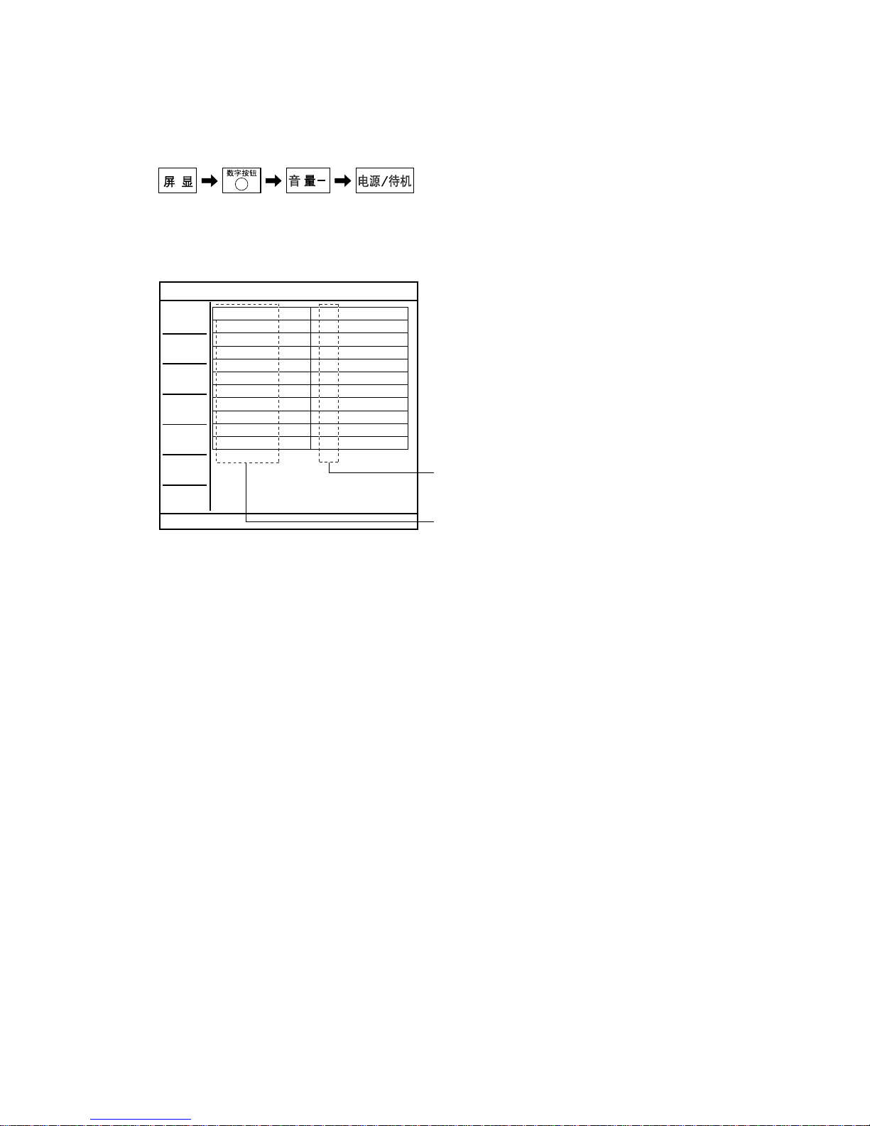
1-4. SELF-DIAGNOSTIC SCREEN DISPLAY
For errors with symptoms such as “power sometimes shuts off” or “screen sometimes goes out” that cannot be confirmed, it is possible to
bring up past occurrences of failure for confirmation on the screen:
1-4-1. To Bring Up Screen Test
In standby mode, press buttons on the remote commander sequentially in rapid succession as shown below:
Since the diagnostic results displayed on the screen are not automatically cleared, always check the self-diagnostic screen
After you have completed the repairs, clear the result display to “0”.
1-5. Quitting Self-diagnostic screen
To quit the entire self-diagnostic screen, turn off the power switch on the remote commander or the main unit.
5
*
* : Note that this differs from entering the service mode (volume +)
DC_DET
DC_ALEAT1
DC_ALERT2
DC_ALERT3
BACKLIGHT
TEMPERATURE
AUDIO
AUSD FAN
DFE
B-ENGINE
HFR
0
0
0
0
0
0
0
0
0
0
0
TV
Monitoring Items
Error Count Record
For details, refer to "1-1. DIAGNOSTIC TEST INDICATORS"
[ SELF-DIAGNOSTIC SCREEN DISPLAY ]
Number "0": means that no fault detected.
Number "1": means a fault was detected one time only.

D846660B279CC0D5520DEF8E80C6FD0B0509C3DE5F2E1AA6282FE9404AF74314F140FE080ED95A15
KLV-40/46/52V440A (CH) 8
TABLE OF CONTENTS
SAFETY CHECK-OUT ............................................. 5
SELF DIAGNOSIS FUNCTION ................................ 6
1. DISASSEMBLY ............................................... 1-1
1-1. KLV-40V440A ....................................................... 1-1
1-1-1. REAR COVER AND STAND ASSY
REMOVAL ...................................................... 1-1
1-1-2. AC INLET AND UNDER COVER
REMOVAL ...................................................... 1-2
1-1-3. BG1G BOARD AND IP5 BOARD
REMOVAL ...................................................... 1-3
1-1-4. FRAME REMOVAL ....................................... 1-4
1-1-5. SPEAKER (L) REMOVAL ............................. 1-5
1-1-6. SPEAKER (R) REMOVAL ............................. 1-5
1-1-7. LCD PANEL, H3E BOARD AND
H4 BOARD REMOVAL ................................. 1-6
1-1-8. WIRING LAYOUT ......................................... 1-7
1-2. KLV-46V440A ....................................................... 1-8
1-2-1. REAR COVER AND STAND ASSY
REMOVAL ...................................................... 1-8
1-2-2. AC INLET AND UNDER COVER
REMOVAL ...................................................... 1-9
1-2-3. BG1G BOARD AND IP5 BOARD
REMOVAL .................................................... 1-10
1-2-4. FRAME REMOVAL ..................................... 1-11
1-2-5. SPEAKER (L) REMOVAL ........................... 1-12
1-2-6. SPEAKER (R) REMOVAL ........................... 1-12
1-2-7. LCD PANEL, H3E BOARD AND
H4 BOARD REMOVAL ............................... 1-13
1-2-8. WIRING LAYOUT ....................................... 1-14
1-3. KLV-52V440A ..................................................... 1-15
1-3-1. REAR COVER AND STAND ASSY
REMOVAL .................................................... 1-15
1-3-2. AC INLET AND UNDER COVER
REMOVAL .................................................... 1-16
1-3-3. D4, D5, G5 AND BG1B BOARDS
REMOVAL .................................................... 1-17
1-3-4. FRAME REMOVAL ..................................... 1-18
1-3-5. SPEAKER (L) REMOVAL ........................... 1-19
1-3-6. SPEAKER (R) ................................................ 1-19
1-3-7. LCD PANEL, H3E BOARD AND
H4 BOARD REMOVAL ............................... 1-20
1-3-8. WIRING LAYOUT ....................................... 1-21
2. DIAGRAMS ..................................................... 2-1
2-1. CIRCUIT BOARDS LOCATION ......................... 2-1
(1) KLV-40V440A ................................................ 2-1
(2) KLV-46V440A ................................................ 2-1
(3) KLV-52V440A ................................................ 2-1
3. EXPLODED VIEWS ........................................ 3-1
3-1. KLV-40V440A ....................................................... 3-2
3-1-1. REAR COVER AND STAND ASSY ............. 3-2
3-1-2. CHASSIS-1 ...................................................... 3-3
3-1-3. CHASSIS-2 ...................................................... 3-4
3-2. KLV-46V440A ....................................................... 3-5
3-2-1. REAR COVER AND STAND ASSY ............. 3-5
3-2-2. CHASSIS-1 ...................................................... 3-6
3-2-3. CHASSIS-2 ...................................................... 3-7
3-3. KLV-52V440A ....................................................... 3-8
3-3-1. REAR COVER AND STAND ASSY ............. 3-8
3-3-2. CHASSIS-1 ...................................................... 3-9
3-3-3. CHASSIS-2 .................................................... 3-10
3-4. PACKING MATERIALS .................................... 3-11
3-4-1. KLV-40V440A .............................................. 3-11
3-4-2. KLV-46V440A .............................................. 3-12
3-4-3. KLV-52V440A .............................................. 3-13

D846660B279CC0D5520DEF8E80C6FD0B0509C3DE5F2E1AA6282FE9404AF74314F140FE080ED95A15
KLV-40/46/52V440A (CH) 9

D846660B279CC0D5520DEF8E80C6FD0B0509C3DE5F2E1AA6282FE9404AF74314F140FE080ED95A15
KLV-40/46/52V440A (CH) 1-1
1-1. KLV-40V440A
1-1-1. REAR COVER AND STAND ASSY REMOVAL
SECTION 1
DISASSEMBLY
3 Six screws
(+BVTP2 4X16)
3 Four screws
(+BVTP2 4X16)
3 Five screws
(+BVTP2 4X16)
3 Two screws
(+BVTP2 4X16)
3 Two screws
(+BVTP2 4X16)
6 Two screws
(+BV 3X12,
TYPE2, IT-3)
4 Two screws
(+PSW M5X8)
4 Two screws
(+PSW M5X8)
5Two screws
(+PSW M5X16)
7 Rear cover (40) assy
8 Switch unit
1 Three screws
(+PSW M5X16)
2 Stand assy (L)
D846660B279CC0D5520DEF8E80C6FD0B0509C3DE5F2E1AA6282FE9404AF74314F140FE080ED95A15
KLV-40/46/52V440A (CH) 1-2
KLV-40V440A
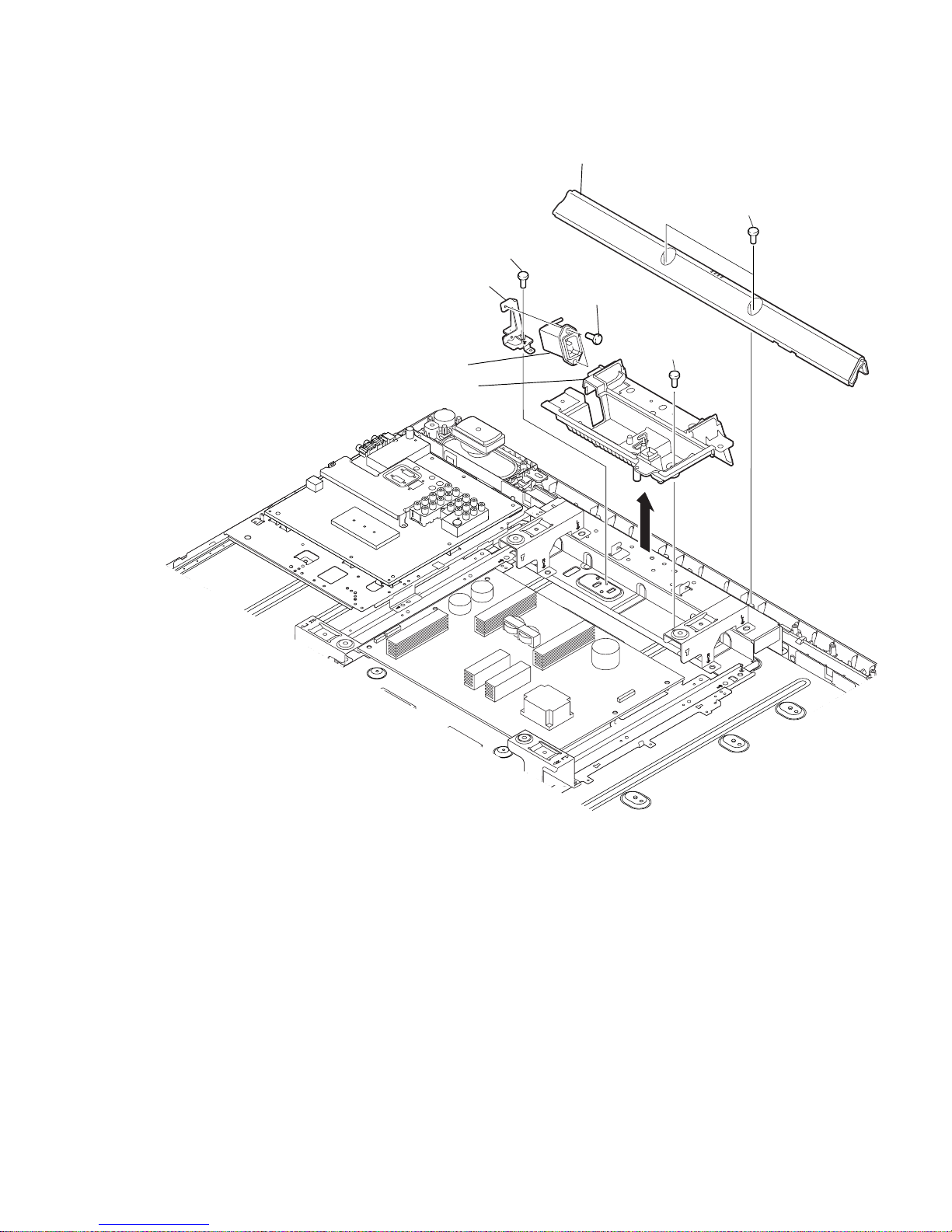
1-1-2. AC INLET AND UNDER COVER REMOVAL
1 Two screws
(+BVTP2 4X16)
7 Two screws
(+BVST 3X8)
5 Two screws
(+KTT 3X10(S TYPE))
3 One screw
(+BVST 3X8)
4 Under cover (L2)
2 Under bar (L)
6 AC inlet
8 AC inlet bracket
D846660B279CC0D5520DEF8E80C6FD0B0509C3DE5F2E1AA6282FE9404AF74314F140FE080ED95A15
KLV-40/46/52V440A (CH) 1-3
KLV-40V440A
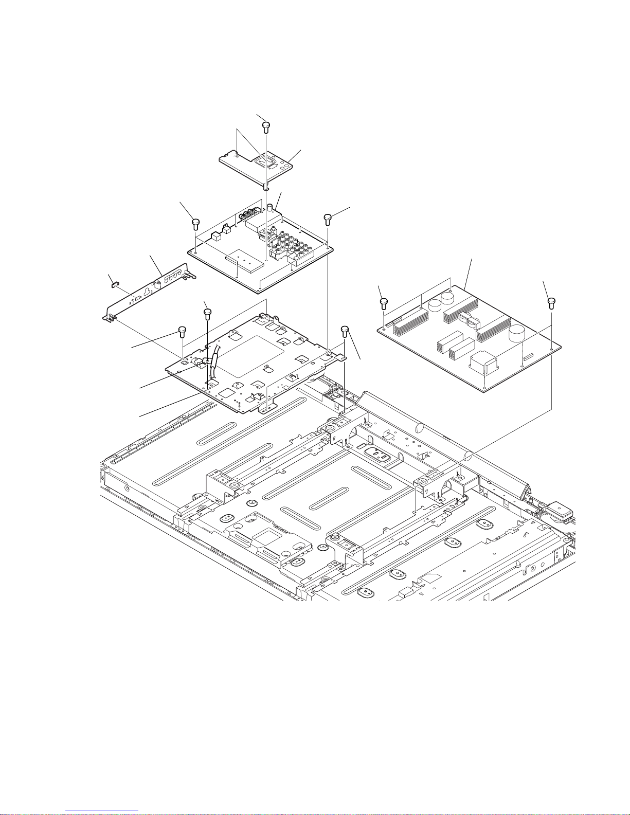
1-1-3. BG1G BOARD AND IP5 BOARD REMOVAL
1 Three screws
(+BVST 3X8)
1 Three screws
(+BVST 3X8)
3 Two screws
(+BVST 3X8)
4 B(G)shild
5 Side jack
bracket assy
6 MS cover
8 BG1G board
7 Four screws
(+BVST 3X8)
9 One screws
(+PSW M5X8)
0 Harness with
connector(LVDS)
qa Two screws
(+BVST 3X8)
qa Two screws
(+BVST 3X8)
qs G5 frame
7 Five screws
(+BVST 3X8)
2 IP5 board
D846660B279CC0D5520DEF8E80C6FD0B0509C3DE5F2E1AA6282FE9404AF74314F140FE080ED95A15
KLV-40/46/52V440A (CH) 1-4
KLV-40V440A
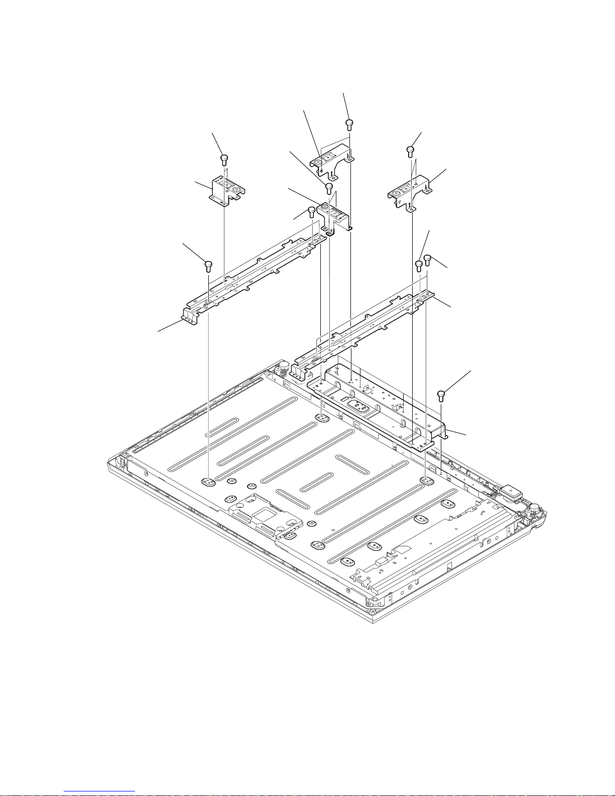
1-1-4. FRAME REMOVAL
qh Bottom frame
assy
7 Spine frame assy
qf Spine frame assy
1 Two screws
(+PSW M5X8)
5 Two screws
(+PSW M4X8)
qs Two screws
(+PSW M4X8)
6 One screw
(+PSW M4X8)
8 Two screws
(+PSW M5X8)
4 Vesa frame (BTM) assy
qa Vesa frame (BTM)
assy
2 Vesa frame (TOP)
9 Vesa frame
(TOP)
3 Two screws (+BVST 3X8)
0 Two screws (+BVST 3X8)
qg Four screws
(+BVTP2 4X16)
qd One screw
(+PSW M4X8)
D846660B279CC0D5520DEF8E80C6FD0B0509C3DE5F2E1AA6282FE9404AF74314F140FE080ED95A15
KLV-40/46/52V440A (CH) 1-5
KLV-40V440A
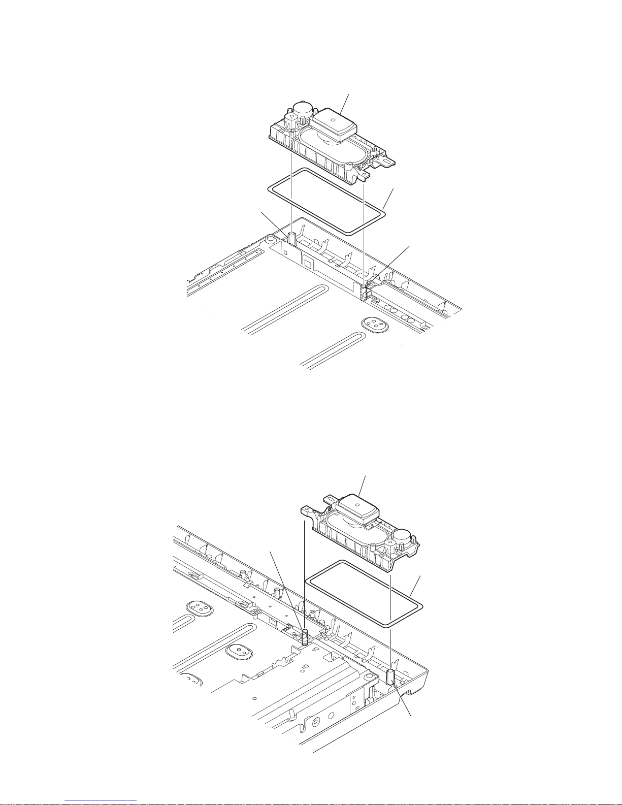
1-1-5. SPEAKER (L) REMOVAL
1 Loudspeaker (3CM, 5.8X12.6CM)
Both
Both
2 Speaker cushion
1 Loudspeaker (3CM, 5.8X12.6CM)
2 Speaker cushion
Both
Both
1-1-6. SPEAKER (R) REMOVAL
 Loading...