

Sony KLV-46F300A, KLV-40F310A, KLV-46F310A Service Manual
5B6E056B0DBC8C3EA98124D4035F0D2DAA0CF7903190433B89A3B4E280BF52152952806CB7B5A285
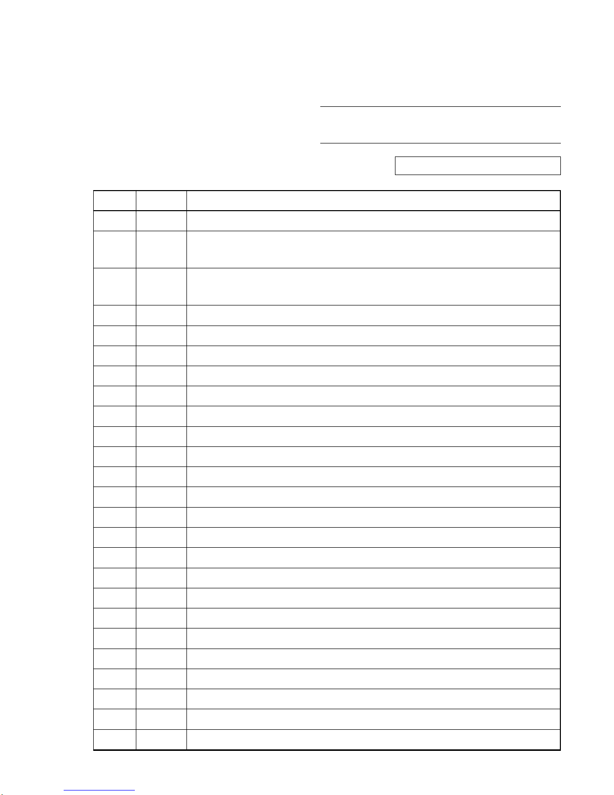
Ver. DATA CONTENTS
1.0 2007.09 Issued
1.1 2007.11 Addition of KLV-40F310A/46F310A Models.
(P. 1 to P. 3, P. 1-1 to P. 1-7, P2-1, P. 3-1 to P. 3-9)
1.2 2008.01 Correction and Addition of parts number for SEC. 3 EXPLODED VIEWS.
(P. 3-3, P. 3-4)
MODEL NAME : KLV-40/46F300A, 40/46F310A
SERVICE MANUAL
PARTS No. : 9-834-179-03
MODIFICATION HISTORY
* Blue characters are linking.
5B6E056B0DBC8C3EA98124D4035F0D2DAA0CF7903190433B89A3B4E280BF52152952806CB7B5A285
LCD Color TV
WAX3
CHASSIS
China Model
KLV-40F300A/46F300A
SERVICE MANUAL
KLV-40F310A/46F310A
5B6E056B0DBC8C3EA98124D4035F0D2DAA0CF7903190433B89A3B4E280BF52152952806CB7B5A285
KLV-40/46F300A, 40/46F310A (CH) 2
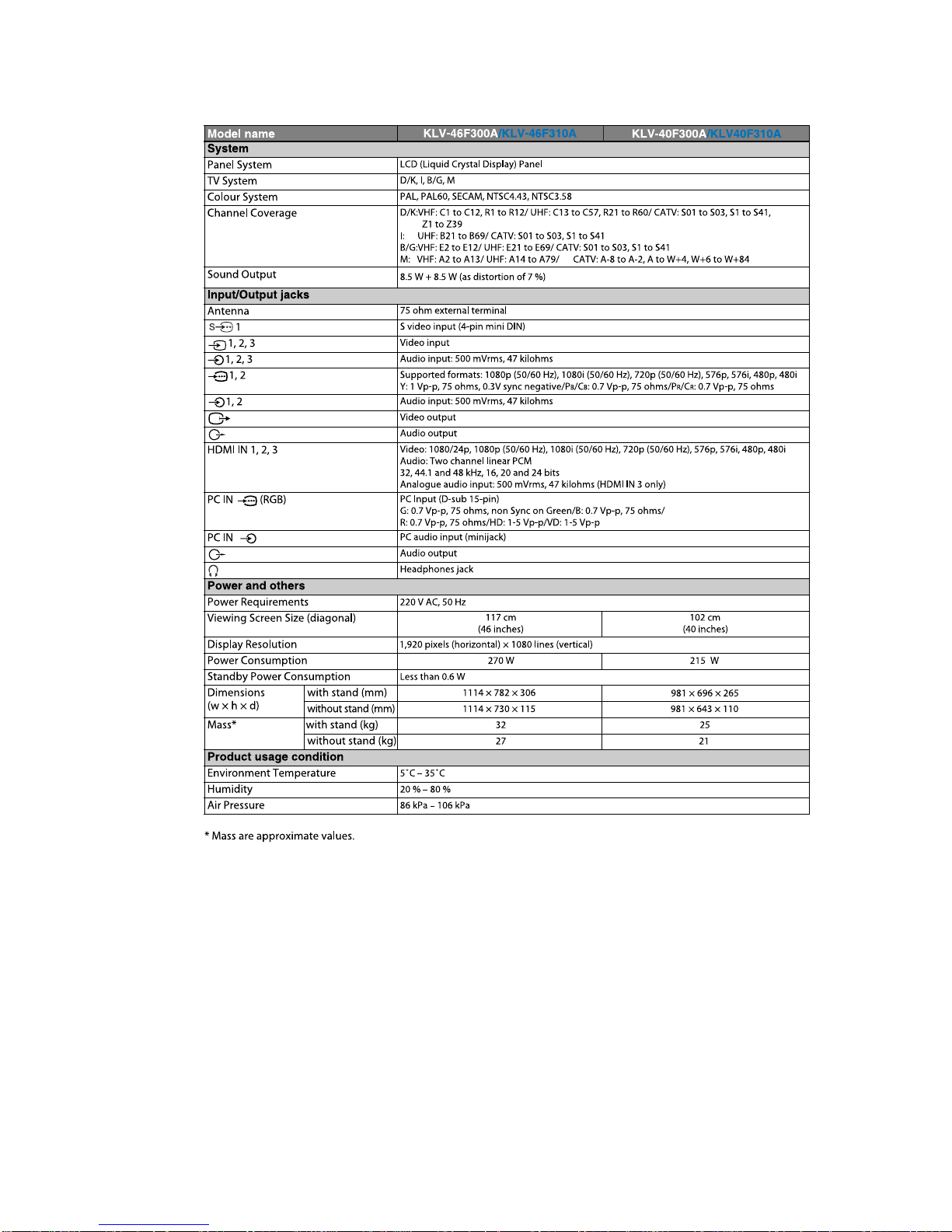
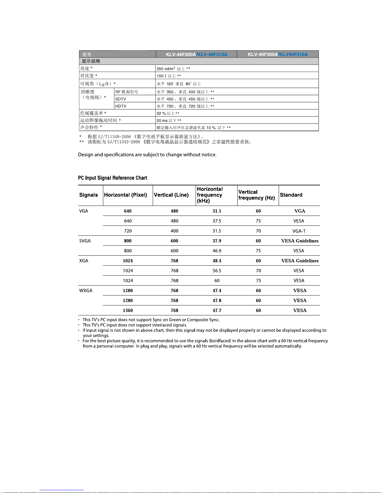
SPECIFICATIONS
5B6E056B0DBC8C3EA98124D4035F0D2DAA0CF7903190433B89A3B4E280BF52152952806CB7B5A285
KLV-40/46F300A, 40/46F310A (CH) 3

5B6E056B0DBC8C3EA98124D4035F0D2DAA0CF7903190433B89A3B4E280BF52152952806CB7B5A285
KLV-40/46F300A, 40/46F310A (CH) 4
CAUTION
These servicing instructions are for use by qualified service
personnel only.
To reduce the risk of electric shock, do not perform any servicing
other than that contained in the operating instructions unless you
are qualified to do so.
WARNING!!
An isolation transformer should be used during any service to
avoid possible shock hazard, because of live chassis.
The chassis of this receiver is directly connected to the ac power
line.
! SAFETY-RELATED COMPONENT
WARNING!!
Replace all components with Sony parts whose part numbers
appear as shown in this manual or in supplements
published by Sony.
WARNINGS AND CAUTIONS SAFETY-RELATED COMPONENT
WARNING
It is essential that all critical parts be replaced only with the part
number specified in the electrical parts list to prevent electric
shock, fire, or other hazard.
NOTE: Do not modify the original design without obtaining
written permission from the manufacturer or you will
void the original parts and labor guarantee.
USE CAUTION WHEN HANDLING THE LCD PANEL
When repairing the LCD panel, be sure you are grounded by
using a wrist band.
When repairing the LCD panel on the wall, the LCD panel must
be secured using the 4 mounting holes on the rear cover.
1) Do not press on the panel or frame edge to avoid the risk of
electric shock.
2) Do not scratch or press on the panel with any sharp objects.
3) Do not leave the module in high temperatures or in areas of
high humidity for an extended period of time.
4) Do not expose the LCD panel to direct sunlight.
5) Avoid contact with water. It may cause a short circuit within
the module.
6) Disconnect the AC power when replacing the backlight (CCFL)
or inverter circuit.
(High voltage occurs at the inverter circuit at 650Vrms.)
7) Always clean the LCD panel with a soft cloth material.
8) Use care when handling the wires or connectors of the inverter
circuit. Damaging the wires may cause a short.
9) Protect the panel from ESD to avoid damaging the electronic
circuit (C-MOS).

5B6E056B0DBC8C3EA98124D4035F0D2DAA0CF7903190433B89A3B4E280BF52152952806CB7B5A285
KLV-40/46F300A, 40/46F310A (CH) 5
SAFETY CHECK-OUT
After correcting the original service problem, perform the
following safety checks before releasing the set to the customer:
1. Check the area of your repair for unsoldered or poorly
soldered connections. Check the entire board surface for
solder splashes and bridges.
2. Check the interboard wiring to ensure that no wires are
“pinched” or touching high-wattage resistors.
3. Check that all control knobs, shields, covers, ground straps,
and mounting hardware have been replaced. Be absolutely
certain that you have replaced all the insulators.
4. Look for unauthorized replacement parts, particularly
transistors, that were installed during a previous repair. Point
them out to the customer and recommend their replacement.
5. Look for parts which, though functioning, show obvious
signs of deterioration. Point them out to the customer and
recommend their replacement.
6. Check the line cords for cracks and abrasion. Recommend
the replacement of any such line cord to the customer.
7. Check the antenna terminals, metal trim, “metallized”
knobs, screws, and all other exposed metal parts for AC
leakage. Check leakage as described below.
Leakage Test
The AC leakage from any exposed metal part to earth ground
and from all exposed metal parts to any exposed metal part
having a return to chassis, must not exceed 0.5 mA (500
microamperes).
Leakage current can be measured by any one of three methods.
1. A commercial leakage tester, such as the Simpson 229 or
RCA WT-540A. Follow the manufacturers’ instructions to
use these instructions.
2. A battery-operated AC milliampmeter. The Data Precision
245 digital multimeter is suitable for this job.
3. Measuring the voltage drop across a resistor by means of a
VOM or battery-operated AC voltmeter. The “limit”
indication is 0.75 V, so analog meters must have an accurate
low voltage scale.
The Simpson’s 250 and Sanwa SH-63TRD are examples of
passive VOMs that are suitable. Nearly all battery-operated
digital multimeters that have a 2 VAC range are suitable (see
Figure A).
How to Find a Good Earth Ground
A cold-water pipe is a guaranteed earth ground; the cover-plate
retaining screw on most AC outlet boxes is also at earth ground.
If the retaining screw is to be used as your earth ground, verify
that it is at ground by measuring the resistance between it and a
cold-water pipe with an ohmmeter. The reading should be zero
ohms.
If a cold-water pipe is not accessible, connect a 60- to 100-watt
trouble- light (not a neon lamp) between the hot side of the
receptacle and the retaining screw. Try both slots, if necessary,
to locate the hot side on the line; the lamp should light at normal
brilliance if the screw is at ground potential (see Figure B).
Exposed Meta
l
Parts on Se
t
.15
µ
Earth Groun
d
AC
0.75V
)
ouble Ligh
t
AC Outlet Box
Ohmmeter
Col
d-water Pi
pe
FigureA. Using an AC voltmeter to check AC leakage. Figure B. Checking for earth ground
.
5B6E056B0DBC8C3EA98124D4035F0D2DAA0CF7903190433B89A3B4E280BF52152952806CB7B5A285
KLV-40/46F300A, 40/46F310A (CH) 6
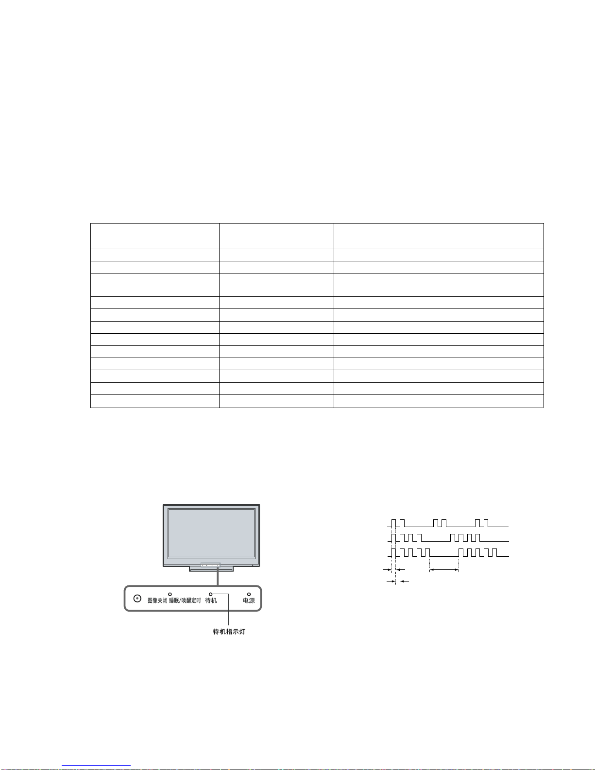
SELF DIAGNOSIS FUNCTION
The units in this manual contain a self-diagnostic function. If an error occurs, the STANDBY LED will automatically begin to flash.
The number of times the LED flashes translates to a probable source of the problem.
A definition of the STANDBY LED flash indicators is listed in the instruction manual for the user’s knowledge and reference.
If an error symptom cannot be reproduced, the remote commander can be used to review the failure occurrence data stored in memory to
reveal past problems and how often these problems occur.
1-1. DIAGNOSTIC TEST INDICATORS
When an error occurs, the STANDBY LED will flash a set number of times to indicate the possible cause of the problem.
If there is more than one error, the LED will identify the first of the problem areas.
Result for all of the following diagnostic items are displayed on screen.
If the screen displays a “0”, no error has occurred .
Number of times STANDY LED Monitoring Items
Diagnostic Item Description
(Red) flashes (Screen Display)
2 times DC_DET Main power supply voltage error (12V, etc)
3 times DC_ALERT1 Malfunction of 3.3V line (Trident circuit, etc)
4 times DC_ALERT2 Malfunction of 5V line
(Voltage Supply to FE, etc)
5 times DC_ALERT3 Malfunction of power supply for screen
6 times BACKLIGHT Malfunction of inverter or overcurrent, etc
7 times
*2
TEMPERATURE Abnormal temperature inside unit
8 times AUDIO Audio circuit error (amplifier, etc.)
9 times AUSD FAN
*3
Fan malfunction
10 times DEF Digital FE circuit error
11 times B-ENGINE Malfunction of Trident IC or around IC
12 times HFR BH board error
*1
13 times (No item on screen display) Malfunction of balancer
*1: When safety shutdown occurs because of FRC ACK, 1.5V line, 2.5V/3.3V line, or Panel 12V malfunction, BH board is considered
to be abnormal.
*2: If abnormal temperature of BH board occurs, STANDY LED flashes is same as abnormal temperature inside unit, the error is
differentiated by shot unit down or not. When the unit shut down, abnormal temperature inside unit occurs.
*3: No item on screen display
1-2. DISPLAY OF STANDBY/TIMER LIGHT FLASH COUNT
1-3. STOPPING THE STANDBY FLASH
Turn off the power switch on the TV main unit or unplug the power cord from the outlet to stop the STANDBY LED from flashing.
2 times
4 times
5 times
LED ON 0.3 sec.
LED OFF 0.3 sec.
LED OFF
3 sec.
[ FLASH COUNT ]
Note: One flash counts is not self-diagnostic.
5B6E056B0DBC8C3EA98124D4035F0D2DAA0CF7903190433B89A3B4E280BF52152952806CB7B5A285
KLV-40/46F300A, 40/46F310A (CH) 7
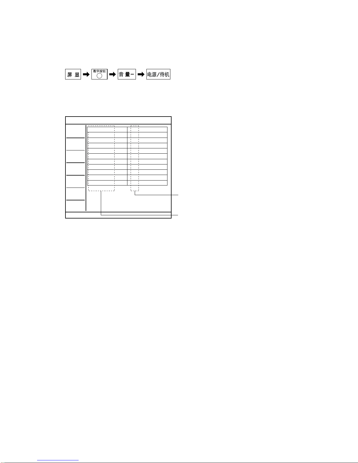
1-4. SELF-DIAGNOSTIC SCREEN DISPLAY
For errors with symptoms such as “power sometimes shuts off” or “screen sometimes goes out” that cannot be confirmed, it is possible to
bring up past occurrences of failure for confirmation on the screen:
1-4-1. To Bring Up Screen Test
In standby mode, press buttons on the remote commander sequentially in rapid succession as shown below:
Since the diagnostic results displayed on the screen are not automatically cleared, always check the self-diagnostic screen
After you have completed the repairs, clear the result display to “0”.
1-5. Quitting Self-diagnostic screen
To quit the entire self-diagnostic screen, turn off the power switch on the remote commander or the main unit.
5
*
* : Note that this differs from entering the service mode (volume +)
DC_DET
DC_ALEAT1
DC_ALERT2
DC_ALERT3
BACKLIGHT
TEMPERATURE
AUDIO
AUDIO FAN
DFE
B-ENGINE
HFR
0
0
0
0
0
0
0
0
0
0
0
TV
Monitoring Items
Error Count Record
For details, refer to "1-1. DIAGNOSTIC TEST INDICATORS"
[ SELF-DIAGNOSTIC SCREEN DISPLAY ]
Number "0": means that no fault detected.
Number "1": means a fault was detected one time only.

5B6E056B0DBC8C3EA98124D4035F0D2DAA0CF7903190433B89A3B4E280BF52152952806CB7B5A285
KLV-40/46F300A, 40/46F310A (CH) 8
TABLE OF CONTENTS
SAFETY CHECK-OUT ............................................. 5
SELF DIAGNOSIS FUNCTION ................................ 6
1. DISASSEMBLY ............................................... 1-1
1-1. KLV-40/46F300A, 40/46F310A ............................ 1-1
1-1-1. REAR COVER REMOVAL............................ 1-1
1-1-2. STAND ASSY AND VESA ARM ASSY
REMOVAL ...................................................... 1-1
1-1-3. H1 BOARD REMOVAL ................................. 1-2
1-1-4. U2B BOARD AND SIDE TERMINAL
REMOVAL ...................................................... 1-2
1-1-5. G3 AND DF1/DF2 BOARDS REMOVAL .... 1-3
1-1-6. DTT (TOP) SHIELD REMOVAL .................. 1-3
1-1-7. BG1F/UT BOARD REMOVAL ..................... 1-4
1-1-8. AC INLET AND UNDER COVER
REMOVAL ...................................................... 1-4
1-1-9. LCD BKT BTM L/R ASSY ............................ 1-5
1-1-10. SPEAKER REMOVAL ................................... 1-5
1-1-11. H3 AND H4 BOARDS REMOVAL ............... 1-6
1-1-12. D3 BOARD REMOVAL
(KLV-46F300A/46F310A) .............................. 1-6
1-1-13. LCD PANEL AND BEZEL ASSY
REMOVAL ...................................................... 1-7
2. DIAGRAMS ..................................................... 2-1
2-1. CIRCUIT BOARDS LOCATION ......................... 2-1
3. EXPLODED VIEWS ........................................ 3-1
3-1. KLV-40/46F300A, 40/46F310A ............................ 3-2
3-1-1. REAR COVER AND STAND ASSY ............. 3-2
3-1-2. CHASSIS-1 ...................................................... 3-3
3-1-3. CHASSIS-2 ...................................................... 3-4
3-1-4. CHASSIS-3 ...................................................... 3-5
3-1-5. SPEAKER ........................................................ 3-6
3-1-6. BEZEL ASSY AND LCD PANEL ................. 3-7
3-2. PACKING MATERIALS
(KLV-40F300A/40F310A) .................................... 3-8
3-3. PACKING MATERIALS
(KLV-46F300A/46F310A) .................................... 3-9
 Loading...