

Sony KLV-32R306B, KDL-32R304B, KDL-40R350B, KLV-40R352B, KLV-32R302B Service Manual
HISTOR Y INFORMATION FOR THE FOLLOWING MANUAL:
SERVICE MANUAL (UNIQUE)
ITC3.5CHASSIS
Segment: SE-Pan Asia
Version Date Subject
1 7/2014 1stIssue.
2 9/2014 Part Information Changed (Pg 19, 23)
LCD TV
9-888-162-P2
F
or SM -Common , please refer :
9-888-162-XX

SERVICE MANUAL (UNIQUE)
ITC3.5CHASSIS
Segment: SE-Pan Asia
LCD TV
MODEL LIST
MODEL REMOTE DESTINATION
KDL-32R300B RM-ED054 SOMEA AF1 (South Africa, Iran, Saudi Arabia,
Kuwait, UAE etc), SSEA SP1 (Singapore,Brunei,
Cambodia, Myanmar, Indonesia etc)
,
Vietnam
,
Malaysia, Thailand, Indonesia.
KDL-32R304B RM-ED054 ME7
KLV-32R302B RM-GA024 SOMEA AF1 (South Africa, Iran, Saudi Arabia,
Kuwait, UAE etc)
,
SSEA SP1 (
Singapore,Brunei
,
Cambodia, Myanmar, Indonesia etc) ,
Philippines.
KLV-32R306B RM-GA024 ME7
KDL-40R350B
RM-ED054
SOMEA AF1 (South Afri
ca, Iran, Saudi Arabia,
Kuwait, UAE etc), SSEA SP1 (Singapore,Brunei,
Cambodia, Myanmar, Indonesia etc) , Vietnam,
Malaysia, Indonesia.
KLV-40R352B RM-GA024 SOMEA AF1 (South Africa, Iran, Saudi Arabia,
Kuwait, UAE etc), SSEA SP1 (
Singapore,Brunei
,
Cambodia, Myanmar, Indonesia etc) ,
Philippines.
3

TABLE OF CONTENTS
Section Title Page
1. SAFETY NOTES
1-1. How to Remove TV Stand………..………………………….. 5
1-2. How to Remove Under Cover……………………………….. 6
1-3. How to Remove B-Board…………………………………….. 7
1-4. How to Remove Main Bracket………………………………. 8
1-5. How to Remove Stand Bracket…………… ………………… 9
1-6. How to Remove Ornamental Panel…… ……………………. 10
1-7. How to Remove H-Board…………………………………….. 11
2. DIAGRAMS
2-1. Circuit Board Location…..………………………………….. 12
2-2. Wire Dressing…………………………………………………. 13
3. DISASSEMBLY, EXPLODED VIEWS AND OTHER PARTS
3-1. KDL, KLV-32R3*B……………………………………………. 17
3-2. KDL, KLV- 40R3*B……………………………………………. 22
Please refer Service Manual – Common for below information :
General Safety Notes
Self Diagnostic Function
Triage Chart
Troubleshooting, Troubleshooting reference
Adjustments
4
Diagrams : Block Diagram , Connector Diagram
Safety Notes
DISSASSEMBLY AND REMOV AL CAUTION
SECTION 1
-
CAUTION: During this disassemble, the TV set must lie above soft cushion / protection sheet. Use glove through out the process.
1
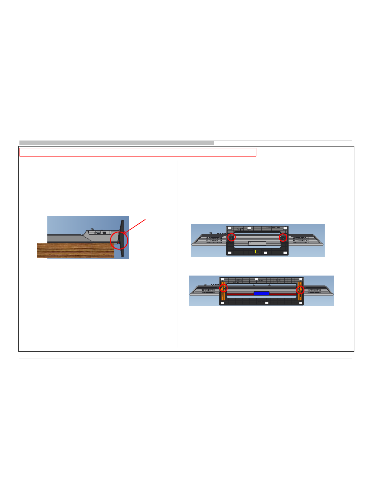
1. How To Remove TV Stand (32/40)
1. Place TV set facing down on a flat surface
2. Remove 2 X SCREW, +PSW M5x20 from bottom and
remove the stand.
◆ MOLD STAND
Make sure
TV stand is
not hitting to
◆ MOLD STAND (32)
the edge of
table
◆ MOLD STAND (40)
5
Safety Notes
-
CAUTION: During this disassemble, the TV set must lie above soft cushion / protection sheet. Use glove through out the process.
Ensure all screws on Under Cover is removed.
1
2
Lift up Under Cover from the
3
Pull out the Under Cover from
1
2. How To Remove
Under Cover (32/40)
SE 32”
bottom side
the slot
SE 40”
6
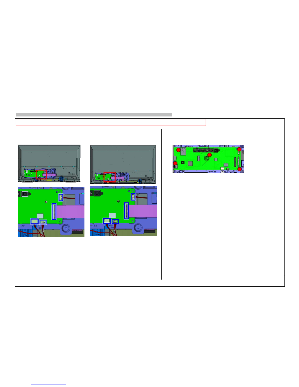
Safety Notes
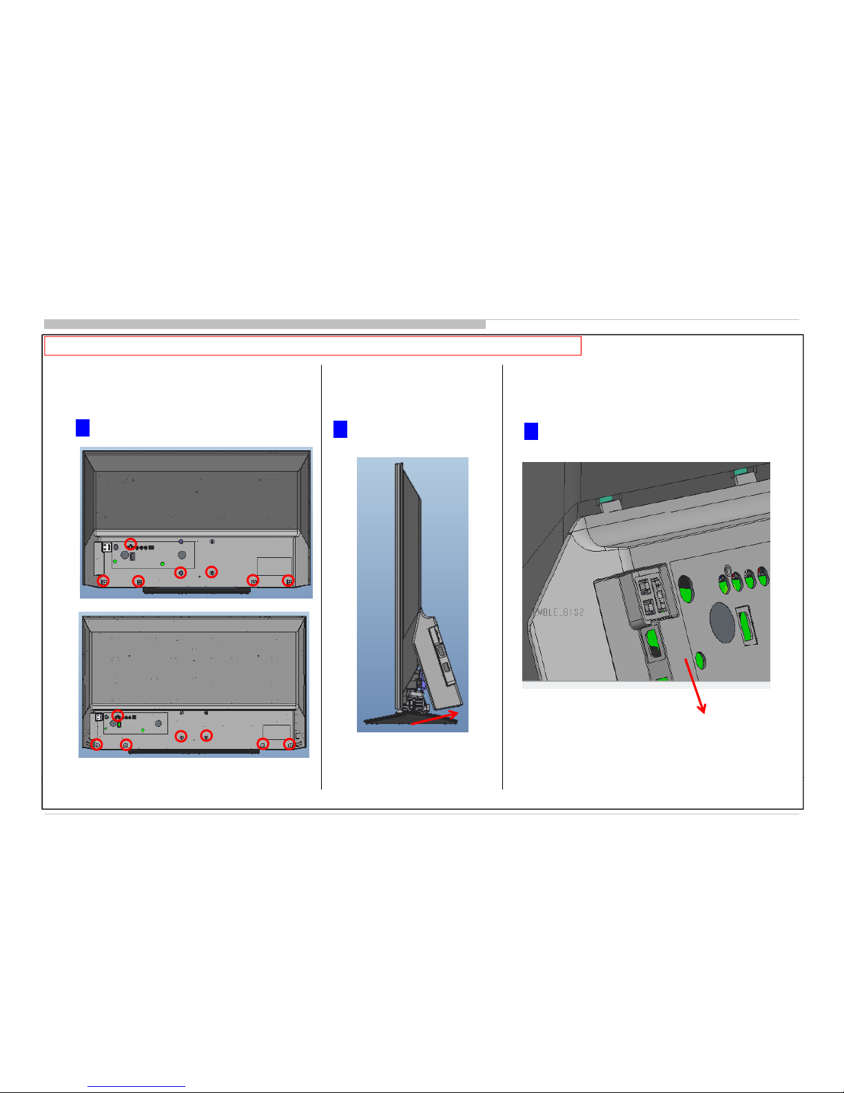
1-3. How To Remove B-Board (BIS2) (32/40)
CAUTION: During this disassemble, the TV set must lie above soft cushion / protection sheet. Use glove through out the process.
1. Remove all the connectors.
SE 32” BIS2 Board SE 40” BIS2 Board
2. Remove all the screws.
-
*
3. Remove B
Board from Main Bracket. Will have sticky feeling
during pulling process due to thermal sheet underneath.
BIS2 Board (5 screw)
7
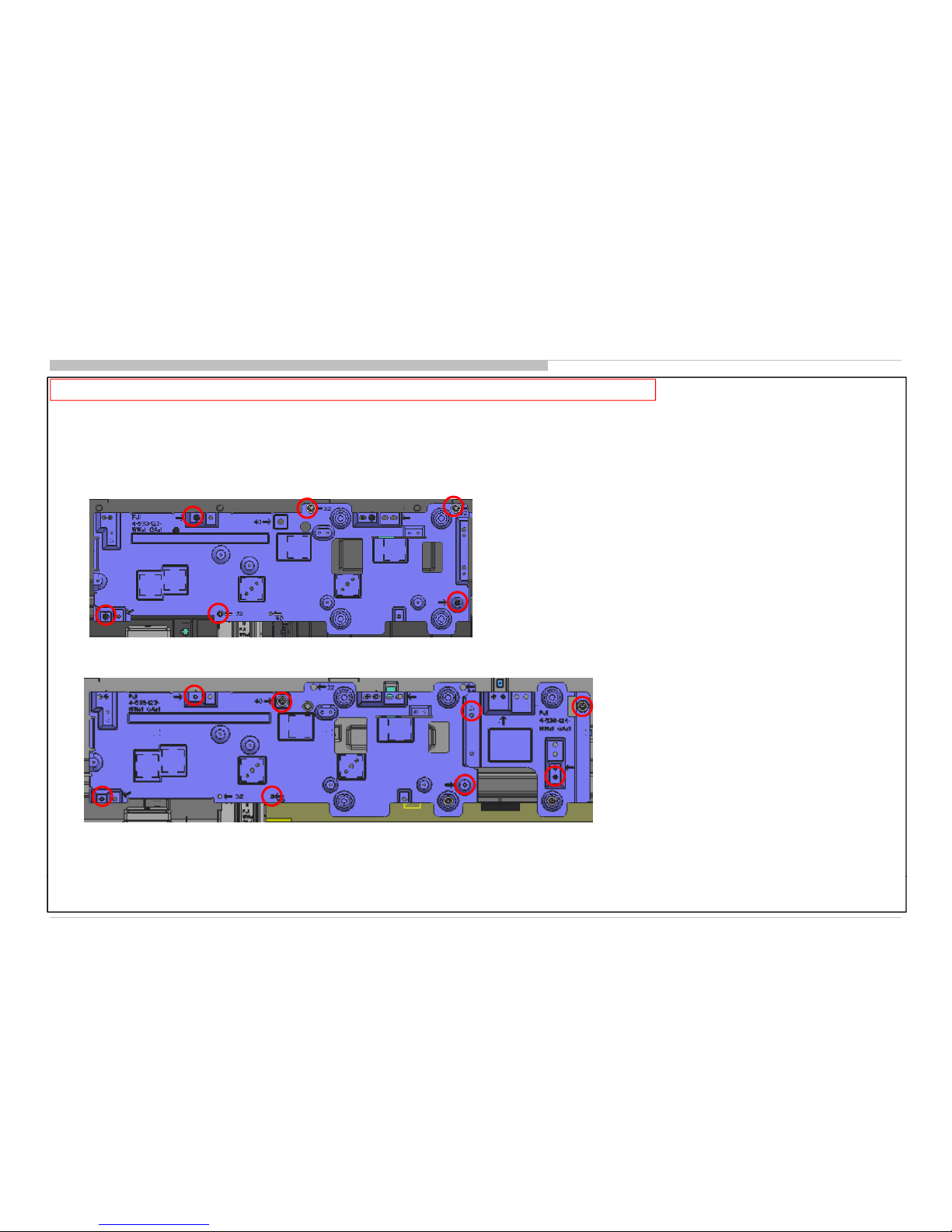
Safety Notes
CAUTION: During this disassemble, the TV set must lie above soft cushion / protection sheet. Use glove through out the process.
1-4. H
ow To Remove Main Bracket
(32/40)
◆ Main Bracket (32) 6 screws
1. Remove all screws.
◆ Main Bracket (40) 8 screws
8
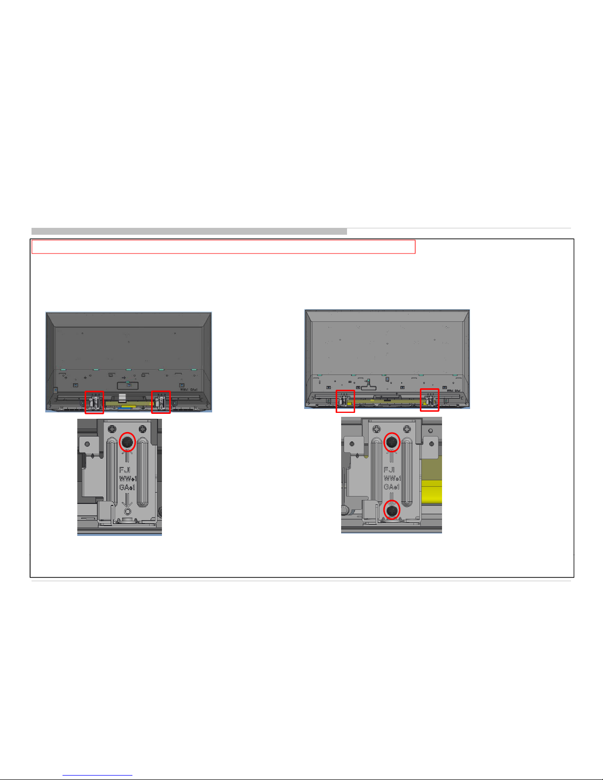
Safety Notes
CAUTION: During this disassemble, the TV set must lie above soft cushion / protection sheet. Use glove through out the process.
1-5. H
ow To Remove Stan
d
B
racket
(32/40)
◆ Stand Bracket (32) 2 screws
◆ Stand Bracket (40) 4 screws
1. Take out screw
9
 Loading...