

SONY KF-42WE620 Service Manual

HISTORY INFORMATION FOR THE FOLLOWING MANUAL:
SERVICE MANUAL
MODEL NAME REMOTE COMMANDER DESTINATION
KF-42WE620
KF-50WE620
RM-Y916 US/CND/MEXICO
RM-Y916 US/CND/MEXICO
LA-2
CHASSIS
ORIGINAL MANUAL ISSUE DATE: 7/2004
REVISION DATE REVISION TYPE SUBJECT
7/2004 No revisions or updates are applicable at this time.
LCD PROJECTION TELEVISION
9-965-969-01
Self Diagnosis
Supported model
SERVICE MANUAL
MODEL NAME REMOTE COMMANDER DESTINATION
KF-42WE620
KF-50WE620
RM-Y916 US/CND/MEXICO
RM-Y916 US/CND/MEXICO
LA-2
CHASSIS
9-965-969-01
KF-50WE620 RM-Y916
LCD PROJECTION TELEVISION

KF-42WE620/50WE620
TABLE OF CONTENTS
SECTION TITLE PAGE SECTION TITLE PAGE
Specifi cations ................................................................................. 4
Warnings and Cautions .................................................................. 5
Safety Check-Out ........................................................................... 6
Self-Diagnostic Function................................................................. 7
SECTION 1: DISASSEMBLY............................................................... 10
1-1. Rear Cover Removal............................................................ 10
1-2. Center Pillar Removal .......................................................... 10
1-3. Service Position ...................................................................11
1-4. Chassis Assembly and D.C. Fan Removal ...........................11
1-5. Power Supply Block Removal (Lamp Drive Unit) ................. 12
1-6. UD Board and RF Antenna Switch Removal........................ 12
1-7. U Board Removal ................................................................. 13
1-8. F and G1 Board Removal .................................................... 13
1-9. DIC Block, AU Board and C2 Board Removal ..................... 14
1-10. A Board Removal ................................................................. 14
1-11. T Board Removal ................................................................. 15
1-12. Front Cover Assembly Removal........................................... 15
1-12-1. Replacing the Lamp................................................. 15
1-13. H3 Board Removal (KF-42WE620 Only) ............................. 16
1-14. H4 Board Removal (KF-42WE610 Only) ............................. 16
1-15. H3 and H4 Board Removal (KF-50WE620 Only)................. 17
1-16. H2 Board Removal............................................................... 17
1-17. H1 Board Removal............................................................... 18
1-18. Screen Mirror Block Assembly Removal.............................. 18
SECTION 2: CIRCUIT ADJUSTMENTS.............................................. 19
2-1. Setting the Service Adjustment Mode .................................. 19
2-2. Service Adjustment Mode Memory ...................................... 19
2-3. Memory Write Confi rmation Method .................................... 20
2-4. Remote Adjustment Buttons and Indicators ......................... 20
2-5. Service Data......................................................................... 21
2-6. ID Map Table........................................................................ 93
3-4. Schematics and Supporting Information ............................ 102
A Board Schematic Diagram (1 of 4).................................. 102
A Board Schematic Diagram (2 of 4).................................. 103
A Board Schematic Diagram (3 of 4).................................. 104
A Board Schematic Diagram (4 of 4).................................. 105
AU Board Schematic Diagram (1 of 2)............................... 108
AU Board Schematic Diagram (2 of 2)............................... 109
G1 Board Schematic Diagram ............................................111
F Board Schematic Diagram ...............................................112
U Board Schematic Diagram (1 of 3) ..................................115
U Board Schematic Diagram (2 of 3) ..................................116
U Board Schematic Diagram (3 of 3) ..................................117
UD Board Schematic Diagram (1 of 2)................................119
UD Board Schematic Diagram (2 of 2)............................... 120
H1 Board Schematic Diagram............................................ 122
H2 Board Schematic Diagram............................................ 124
H3 Board Schematic Diagram............................................ 126
H4 Board Schematic Diagram............................................ 128
T Board Schematic Diagram .............................................. 129
3-5. Semiconductors ................................................................. 130
SECTION 4: EXPLODED VIEWS...................................................... 131
4-1. Cover, Screen Mirror Block ................................................ 131
4-2. Bottom Block ...................................................................... 132
4-3. Chassis - 1 ......................................................................... 133
4-4. Chassis - 2 ......................................................................... 134
4-5. Optical Unit Block ............................................................... 135
SECTION 5: ELECTRICAL PARTS LIST.......................................... 136
SECTION 3: DIAGRAMS..................................................................... 94
3-1. Circuit Boards Location ........................................................ 94
3-2. Printed Wiring Boards and
Schematic Diagrams Information ......................................... 94
3-3. Block Diagrams .................................................................... 96
A Block Diagram (1 of 2) ................................................. 96
A Block Diagram (2 of 2) ................................................. 97
AU Block Diagram ........................................................... 98
G1 Block Diagram ........................................................... 99
H3, H1, H2, and T Block Diagrams ............................... 100
U Block Diagram ........................................................... 101
KF-42WE620/50WE620
3
SPECIFICATIONS
p
)
r
KF-42WE620/50WE620
Power Requirements
Power Consumption (W)
In Use (Max)
In Standby
Inputs/Outputs
120V AC, 60Hz
210W
Under 1 W
DVI-HDTV
1 terminal, 3.3V T.M.D.S., 50 ohms
The DVI-HDTV input terminal is compliant with the EIA-861
standard and is not intended for use with personal computers.
Video (IN)
4 total
1Vp-p, 75ohms unbalanced, sync negative
S Video (IN)
4 total
Y: 1Vp-p, 75ohms unbalanced, sync negative
C: 0.286Vp-p (Burst signal), 75ohms
Audio (IN)
6 total
500 mVrms (100% modulation)
Impedance:47 kilo ohms
Audio (VAR/FIX)
1 total
500 mVrms at the maximum volume setting (Variable)
500 mVrms (Fixed)
Impedance (Output):2 kilo ohm
Control S (IN/OUT)
1 total
Minijacks
Component Video Input
2 (Y, PB, PR)
Y: 1.0 Vp-p, 75 ohms unbalanced, sync negative
PB: 0.7 Vp-p, 75 ohms;
PR: 0.7 Vp-p, 75 ohms
RF Inputs
2 total
Converter
1 total
KF-42WE620 KF-50WE620
S
eaker Output(W
Woofe
Dimensions (W x H x D)
mm 1,201 x 819 x 371 mm 1,377 x 928 x 452 mm
1/4
47
in
x 32
Mass
kg 32 kg 39.5 kg
lbs 70 lbs 12 oz 87 lbs 1 oz
Television system
American TV standard, NTSC
Channel coverage
VHF: 2-13/ UHF: 14-69/ CATV: 1-125
Antenna
75-ohm external antenna terminal for VHF/UHF
Projection System
3 LCD Panels, 1 lens projection system
LCD Panel
0.87 inch TFT LCD panel Approx. 3.28 million dots (1,092,168
pixels)
Projection Lens
High Performance, large diameter hybrid lens F2.4
1/4
x 14
5W x 2
20W
1/2
in 54
Supplied Accessories
Optional Accessories
1/4
x 36
Remote Commander RM-Y916
Two Size AA (R6) Batteries
Cleaning Cloth
TV Stand
SU-GW2 (KF-42WE620 Only)
SU-GW1 (KF-50WE620 Only)
Lamp
XL-2100U
Control S Cable
RK-G69
Component Video Cable
VMC-10/30
AV Receiver
STR series or equivalent
1/2
x 17
3/4
in
KF-42WE620/50WE620
Lamp
UHP lamp, 100W
XL-2100U
Design and specifi cations are subject to change without notice.
4

KF-42WE620/50WE620
WARNINGS AND CAUTIONS
WARNING!!
An isolation transformer should be used during any service to avoid possible shock hazard, because of live chassis. The chassis of
this receiver is directly connected to the AC power line.
! SAFETY-RELATED COMPONENT WARNING!!
Components identifi ed by shading and ! mark on the schematic diagrams, exploded views, and in the parts list are critical for safe
operation. Replace these components with Sony parts whose part numbers appear as shown in this manual or in supplements
published by Sony. Circuit adjustments that are critical for safe operation are identifi ed in this manual. Follow these procedures
whenever critical components are replaced or improper operation is suspected.
ATTENTION!!
Afi n d’eviter tout risque d’electrocution provenant d’un chássis sous tension, un transformateur d’isolement doit etre utilisé lors de tout
dépannage. Le chássis de ce récepteur est directement raccordé à l’alimentation du secteur.
! ATTENTION AUX COMPOSANTS RELATIFS A LA SECURITE!!
Les composants identifi es par une trame et par une marque ! sur les schemas de principe, les vues explosees et les listes de pieces
sont d’une importance critique pour la securite du fonctionnement. Ne les remplacer que par des composants Sony dont le numero
de piece est indique dans le present manuel ou dans des supplements publies par Sony. Les reglages de circuit dont l’importance
est critique pour la securite du fonctionnement sont identifi es dans le present manuel. Suivre ces procedures lors de chaque
remplacement de composants critiques, ou lorsqu’un mauvais fonctionnement suspecte.
KF-42WE620/50WE620
5
SAFETY CHECK-OUT
KF-42WE620/50WE620
After correcting the original service problem, perform the following
safety checks before releasing the set to the customer:
1. Check the area of your repair for unsoldered or poorly soldered
connections. Check the entire board surface for solder splashes and
bridges.
2. Check the interboard wiring to ensure that no wires are “pinched” or
touching high-wattage resistors.
3. Check that all control knobs, shields, covers, ground straps, and
mounting hardware have been replaced. Be absolutely certain that
you have replaced all the insulators.
4. Look for unauthorized replacement parts, particularly transistors,
that were installed during a previous repair. Point them out to the
customer and recommend their replacement.
5. Look for parts which, though functioning, show obvious signs of
deterioration. Point them out to the customer and recommend their
replacement.
6. Check the line cords for cracks and abrasion. Recommend the
replacement of any such line cord to the customer.
7. Check the B+ and HV to see if they are specifi ed values. Make sure
your instruments are accurate; be suspicious of your HV meter if sets
always have low HV.
8. Check the antenna terminals, metal trim, “metallized” knobs, screws,
and all other exposed metal parts for AC leakage. Check leakage as
described below.
Leakage Test
The AC leakage from any exposed metal part to earth ground and
from all exposed metal parts to any exposed metal part having a
return to chassis, must not exceed 0.5 mA (500 microamperes).
Leakage current can be measured by any one of three methods.
1. A commercial leakage tester, such as the Simpson 229 or RCA
WT-540A. Follow the manufacturers’ instructions to use these
instructions.
2. A battery-operated AC milliampmeter. The Data Precision 245
digital multimeter is suitable for this job.
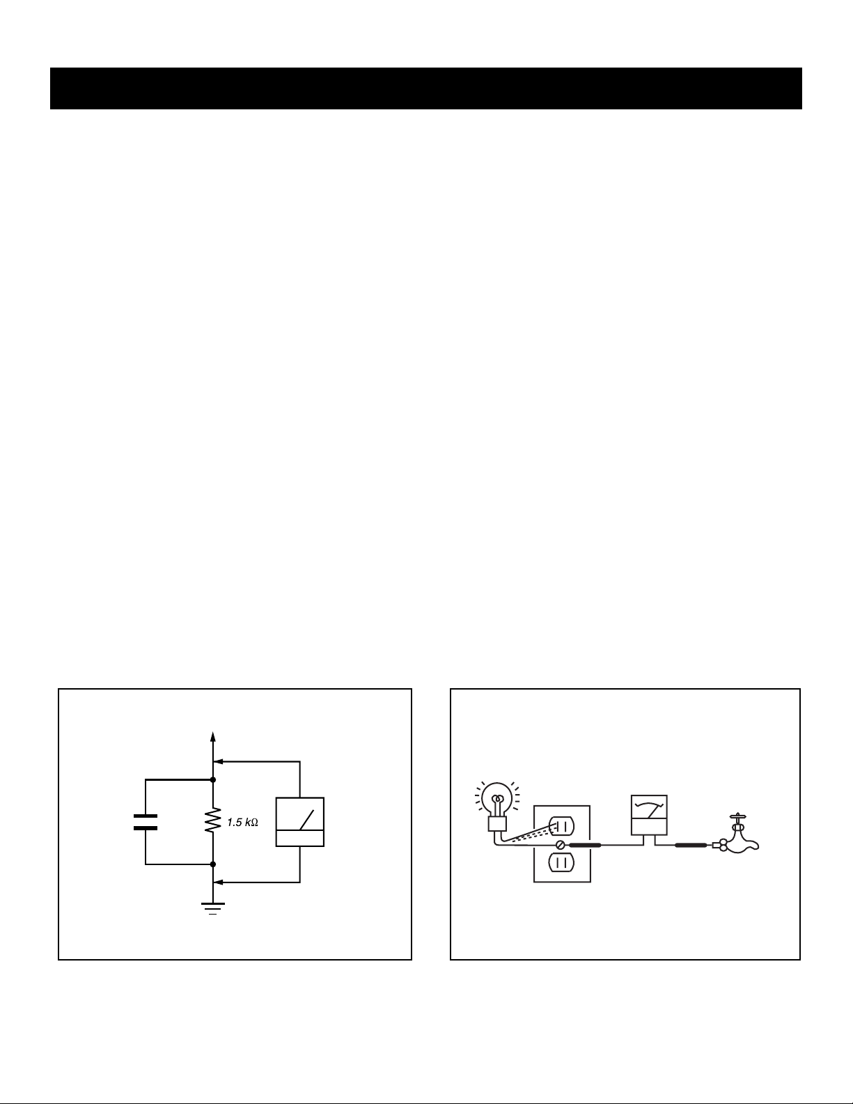
3. Measuring the voltage drop across a resistor by means of a VOM
or battery-operated AC voltmeter. The “limit” indication is 0.75
V, so analog meters must have an accurate low voltage scale.
The Simpson’s 250 and Sanwa SH-63TRD are examples of
passive VOMs that are suitable. Nearly all battery-operated digital
multimeters that have a 2 VAC range are suitable (see Figure A).
How to Find a Good Earth Ground
A cold-water pipe is a guaranteed earth ground; the cover-plate
retaining screw on most AC outlet boxes is also at earth ground. If the
retaining screw is to be used as your earth ground, verify that it is at
ground by measuring the resistance between it and a cold-water pipe
with an ohmmeter. The reading should be zero ohms.
If a cold-water pipe is not accessible, connect a 60- to 100-watt
trouble- light (not a neon lamp) between the hot side of the receptacle
and the retaining screw. Try both slots, if necessary, to locate the hot
side on the line; the lamp should light at normal brilliance if the screw
is at ground potential (see Figure B).
To Exposed Metal
Parts on Set
0.15 F
Figure A. Using an AC voltmeter to check AC leakage. Figure B. Checking for earth ground.
KF-42WE620/50WE620
Earth Ground
AC
Voltmeter
(0.75V)
Trouble Light
AC Outlet Box
Ohmmeter
Cold-water Pipe
6

KF-42WE620/50WE620
SELF-DIAGNOSTIC FUNCTION
Self Diagnosis
Supported model
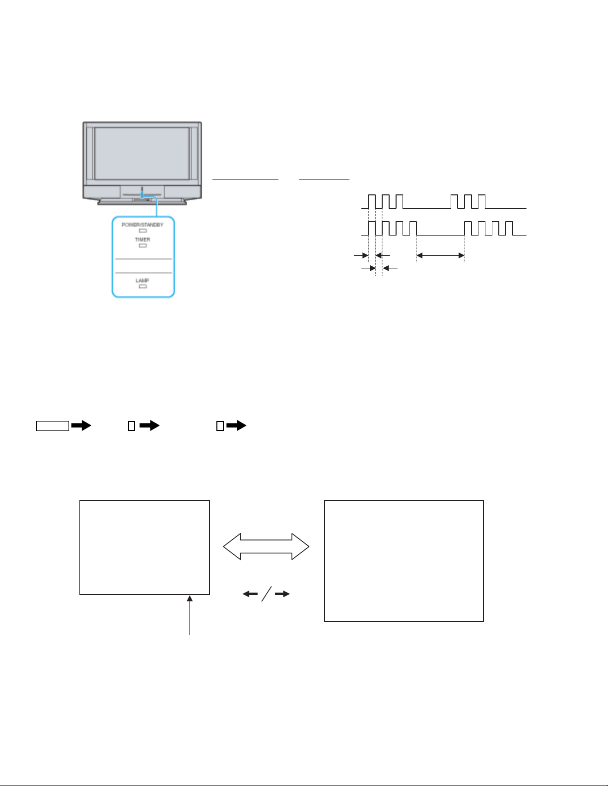
The units in this manual contain a self-diagnostic function. If an error occurs, the POWER/STANDBY will automatically begin to fl ash. The number of
times the LED fl ashes translates to a probable source of the problem. A defi nition of the POWER/STANDBY fl ash indicators is listed in the instruction
manual for the user’s knowledge and reference. If an error symptom cannot be reproduced, the Remote Commander can be used to review the failure
occurrence data stored in memory to reveal past problems and how often these problems occur.
Diagnostic Test Indicators
When an error occurs, the POWER/STANDBY will fl ash a set number of times to indicate the possible cause of the problem. If there is more than one
error, the LED will identify the fi rst of the problem areas.
Results for all of the following diagnostic items are displayed on screen. No error has occurred if the screen displays a “0”.
Diagnostic Item
Description
Power does not turn on 0
Lamp cover error 3 times
Fan stopped 4 times
Temp error 4 times
Lamp driver error 5 times
+B OVP error 6 times
Audio error 7 times
D-OVP error 8 times
Lamp error LAMP-LED flashes
No. of times
POWER/STANDBY
lamp flashes
Probable Cause Location Detected Symptoms
• Power cord is not plugged in.
• Fuse is burned out.
(F1901 on F Board)
• Lamp cover is not attached
securely.
• Fan1, Fan2, or Fan 3 power
is not supplied. .
(A Board)
• Fan connector is not attached
securely
• Temperature is high.
• IIC-E line connector
(CN8023 on A Board,
CN44 on H Board) is not
attached securely.
• Lamp driver is faulty. • No picture/No sound
• +17V is not supplied.
(G1 Board)
• Audio line is shorted.
(A, G1 Board)
• IC8504 (A Board) or IC4704
(AU Board) is faulty.
• PS1601 or 1602 is opened.
(G1 Board)
• +3.3V or +2.5V or 1.8V is
over voltage.
(G3 Board)
• Lamp for the light source has
burnt out.
• Power does not come
on.
• No power is supplied
to the unit.
• AC power supply is
faulty.
• No picture/No sound
• No picture/No sound
• No picture/No sound
• No picture/No sound
• No picture/No sound
• No picture/No sound
• No picture/No sound
KF-42WE620/50WE620
7
KF-42WE620/50WE620
m
k
N
*If a +B overcurrent is detected, stoppage of the vertical defl ection is detected simultaneously. The symptom that is diagnosed fi rst by the
mircrocontroller is displayed on the screen.
Display of POWER/STANDBY Flash Count
- One blink is not used for self-diagnosis.
-Example
Diagnosis ite
LED blinks
Lamp cover 3 times
Fan 4 times
LED ON : 0.3sec
LED OFF : 0.3sec
LED OFF
3.0sec
Stopping the POWER/STANDBY LED Flash
Turn off the power switch on the TV main unit or unplug the power cord from the outlet to stop the POWER/STANDBY lamp from fl ashing.
Self-Diagnostic Screen Display
For errors with symptoms such as “power sometimes shuts off” or “screen sometimes goes out” that cannot be confi rmed, it is possible to bring up past
occurrences of failure on the screen for confi rmation.
To Bring Up Screen Test
In standby mode, press the buttons on the Remote Commander sequentially, in rapid succession, as shown below:
Display
Self-Diagnostic Screen Display
Channel
5
MAI
Sound Volume
-
Power ON
LCD ENGINE
Self Diagnosis SELF DIAGNOSIS
6 : +B OVP 0 1 : LAMP 0
7 : AUDIO 0 3 : LAMP COVER 0
8 : D-OVP 1 4 : FAN 1
101 : WDT 0 Move the joystic
4 : TEMP 0
5 : LAMP DRIVER 0
201 : WDT-ENGINE 0
- Numeral "1" means a fault was detected one time or more.
- Numeral "0" means that no fault was detected.
Handling of Self-Diagnostic Screen Display
Since the diagnostic results displayed on the screen are not automatically cleared, always check the self-diagnostic screen during repairs. When you
have completed the repairs, clear the result display to “0”.
Unless the result display is cleared to “0”, the self-diagnostic function will not be able to detect subsequent faults after completion of the repairs.
KF-42WE620/50WE620
8
KF-42WE620/50WE620
Clearing the Result Display
To clear the result display to “0”, press the buttons on the Remote Commander sequentially when the diagnostic screen is displayed, as shown below:
1. Power off (Set to Standby model)
Display
2.
3. Channel
8
Channel
ENTER
5
Sound Volume
Power ON
4. Wait until the initial setup display appears.
5. Disconnect the AC plug and then reconnect it.
Quitting the Self-Diagnostic Screen
To quit the entire self-diagnostic screen, turn off the power switch on the Remote Commander or the main unit.
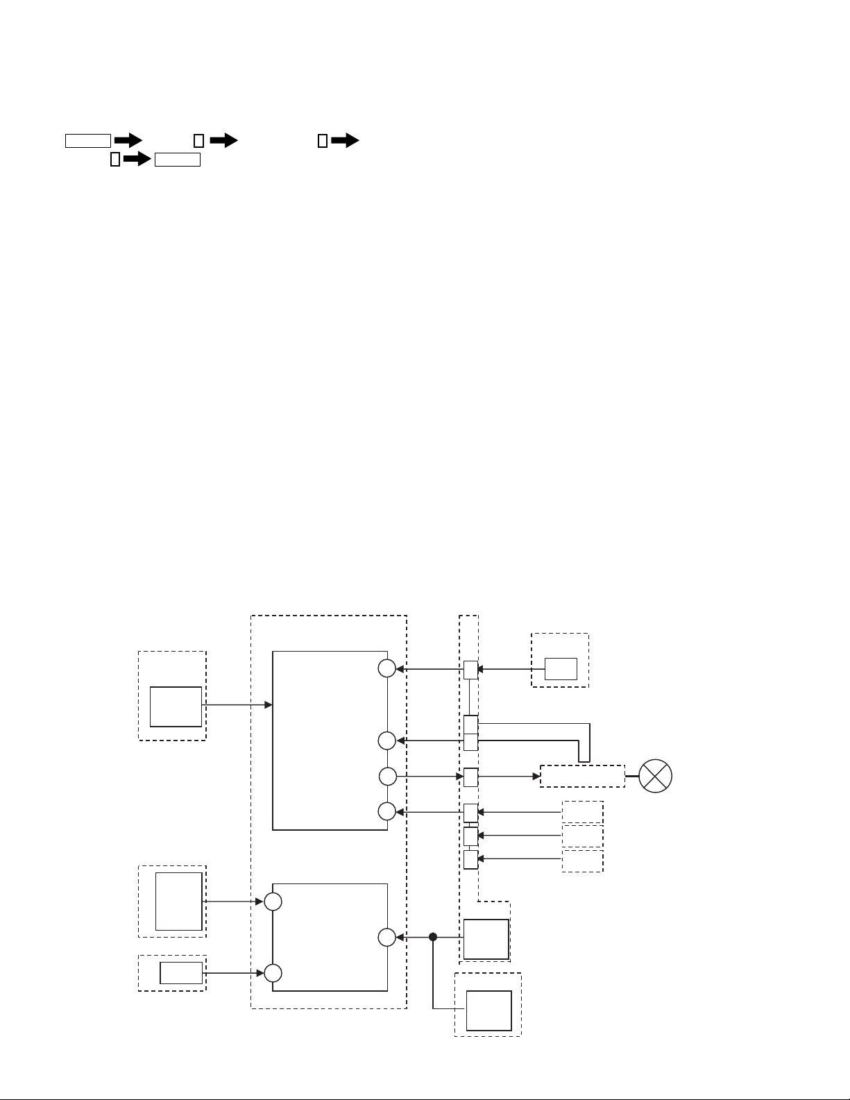
Self-Diagnostic Circuit
Self-Diagnosis Function Operation
- 3 : Lamp cover If the lamp cover SW is opened then pin 1 of CN8034 on the A board is high. The LCD Engine u-com (pin 27 of
IC3208 on the C2 board) detects it and turns the lamp off.
- 4 : Fan If Fan1, Fan2, Fan3, or Fan4 stops then pin 2, 5, 8 or 11 of CN8035 on the A board is high. The LCD Engine
u-com (pin 24 of IC3208 on the C2 board) detects it and turns the lamp off.
- 4 : Temp If a temperature sensor on the H4 board detects a high temperature,
or the IIC-E line connector (CN8041:A board,CN3951 H4 board) is not attached securely, the LCD Engine ucom IIC-E Line detects it and turns the lamp off.
- 5 : Lamp drive If a lamp is not turned on, then pin 29 of LCD Engine u-com (IC3208 on the C2 board) is high and checks pin
28 of LCD Engine u-com. If pin 28 is low, it is judged no high voltage.
- 6 : +BOVP If +17V line drops then pin 53 of MAIN u-com (IC3405 on the C2 board) is low and automatically turns off the
main power.
- 7 : Audio If DC appears by the audio amp failure at the speaker line then it is detected by MAIN u-com (pin 59 of IC3405
on the C2 board) and automatically turns off the main power.
- 8 : D-OVP If +3.3V, +2.5V, or +1.8V line over, then pin 49 of MAIN u-com (IC3405 on the C2 board) is low and
automatically turns off the main power.
- LAMP : Lamp If a lamp is not turned on, then pin 29 of LCD Engine u-com (IC3208 on the C2 board) is high and checks pin
28 of LCD Engine u-com. If pin 28 is high the lamp is burned out.
H3/A board
IC41
Temp
sensor
G3/A board
+3.3V
+2.5V
+1.8V
+17V
G1/A board
4:Temp
8:D-OVP
6:+B OVP
17V-DET
C2 board
IC3208
LCD Engine u-com
LAMP COV
IIC-E
LAMP DRV
LAMP PROT
FAN PROT
IC3405
MAIN u-com
D-OVP
49
SP-DC-PROT
53
LOW-B-ERR
27
28
29
24
59
3:Lamp
cover
5:Lamp
driver
Lamp
4:Fan
CN8022
7:Audio
A board
CN8014
3
2
1
CN8003
1
2
5
8
IC8504
Audio
amp
IC4704
Audio
HV-DET
LAMP-PRT
FAN1-PRT
FAN2-PRT
FAN3-PRT
T/A board
S3999
SW
Lamp driver
Fan1
Fan2
Fan3
Lamp
amp
KF-42WE620/50WE620
AU board
9

1-1. REAR COVER REMOVAL
2
KF-42WE620/50WE620
SECTION 1: DISASSEMBLY
Rear cover
1-2. CENTER PILLAR REMOVAL
Disconnect
three ground wires
Two small screws
(+PSW 3x8)
1
Eleven screws
(+BVTP 4x16)
Gently lift the Center Pillar up then out
5
from the bottom bracket.
Three screws from the top of the center pillar
1
(+BVTP 4x16)
4
2
Center Pillar
KF-42WE620/50WE620
Two screws
(+BVTP 4x16)
3
10
1-3. SERVICE POSITION
r
Chassis assembly
Pull back on claw, then gently pull out chassis assembly
1
KF-42WE620/50WE620
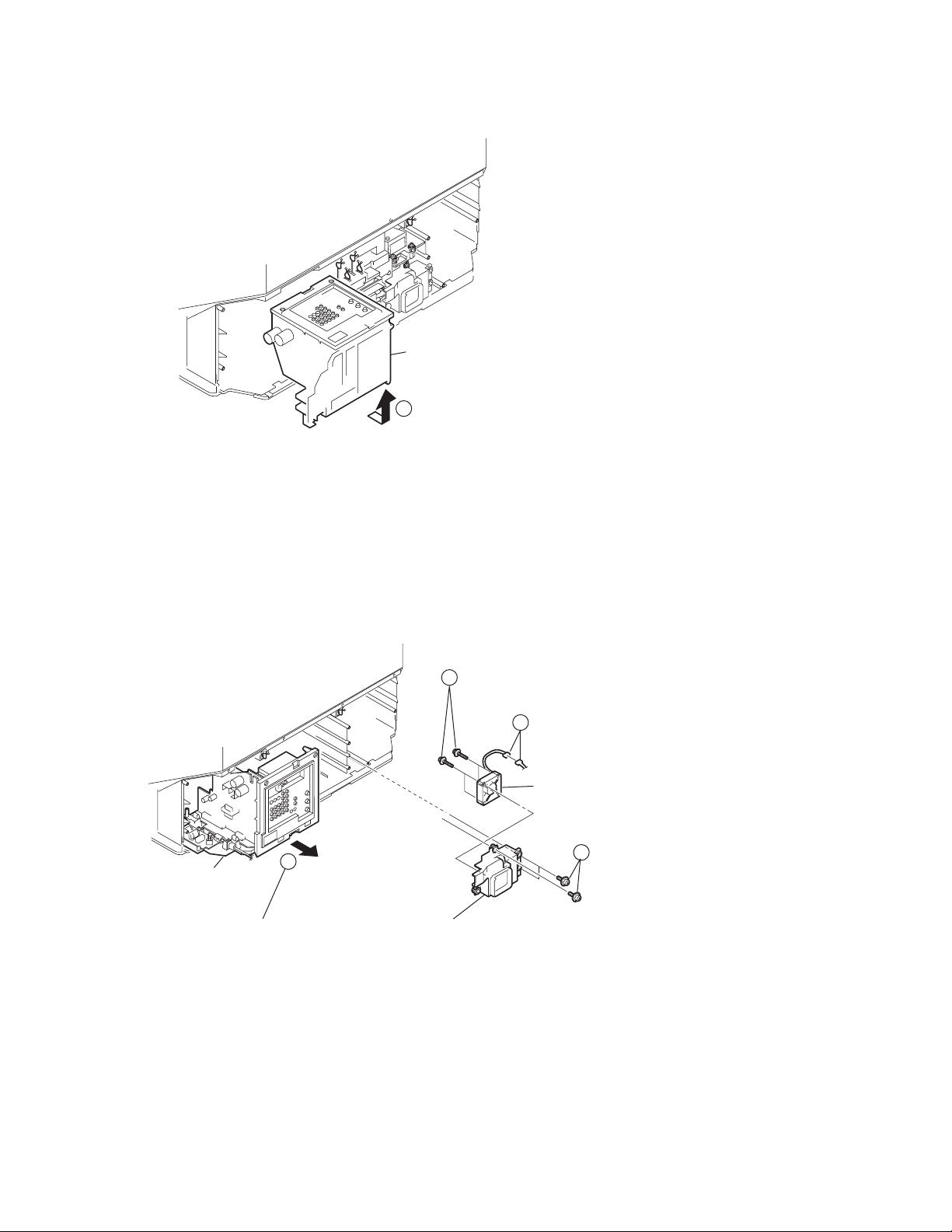
1-4. CHASSIS ASSEMBLY AND D.C. FAN REMOVAL
Four screws
3
(+PWH 4x35)
Chassis assembly
Pull back on claw,
then gently pull out chassis assembly
4
Fan bracket with D. C. fan
2
Disconnect one connecto
D. C. FAN
1
Four screws
(+PWH 4x16)
KF-42WE620/50WE620
11
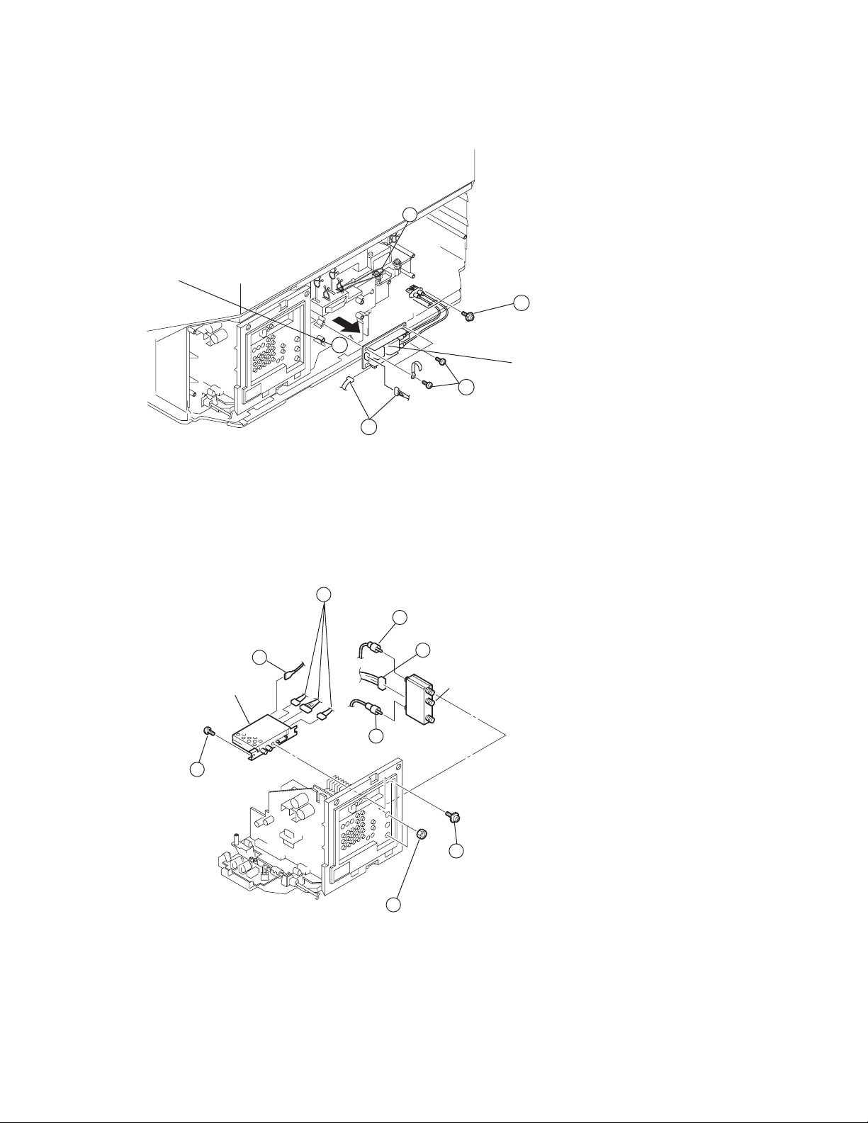
1-5. POWER SUPPLY BLOCK REMOVAL (LAMP DRIVE UNIT)
CAUTION: When removing the Power Supply Block be careful not to move the Optical Unit Block
KF-42WE620/50WE620
Unhook the antenna cable
3
Pull forward to remove
5
4
Four screws (+BVTP 3x12)
1
Disconnect two connectors
1-6. UD BOARD AND RF ANTENNA SWITCH REMOVAL
Disconnect three connectors
and the ground wire
1
1
4
Disconnect two Pin plugs
and one connector
4
2
Two screws (+PWH 4x16)
(to detach the cables from the
Optics Unit Block Assembly)
Power supply block
One screw
(+BVTP 3x8)
KF-42WE620/50WE620
UD board
3
4
5
Two screws (HEX)
RF antenna switch
2
One screw
(+PSW 3x8)
12

1-7. U BOARD REMOVAL
U board
Disconnect three connectors
2
Disconnect four ground wires
1
Six Screws (+BVTP 3x12)
3
U bracket
4
Gently pull back on the two clips
on the pin connection slot
while slowly lifting the U Board
KF-42WE620/50WE620
1-8. F AND G1 BOARD REMOVAL
Note:
Place the F Board on its side
to disconnect three ground wires.
Ttwo screws (+BVTP 3x12)
F board
Disconnect the Power cord
from CN1907 connector.
4
2
Claw
1
Disconnect two connectors (CN1602 & CN1605)
and one ground wire (CN1611)
6
G1 board
Disconnect one connector
(CN1609)
8
7
9
3
Remove wires from purse locks
5
Gently pull back on the two clips
on the pin connection slot
while slowly lifting the G1 Board.
Disconnect one ground wire
KF-42WE620/50WE620
13

1-9. DIC BLOCK, AU BOARD AND C2 BOARD REMOVAL
Note:
The C2 Board is part of the C2 Block Assembly and cannot be ordered separately.
Remove the AU Board after removing the C2 Block Assembly
Note:
2
The 14P Connector Assembly (LVDs cables) have colored tape (white tape)
to indicate which connection they plug into. Please note before removing the cables.
4
Note:
The 14P Connector Assembly (LVDs cables) have colored tape (red tape-right, black tape-left)
to indicate which connection they plug into. Please note before removing the cables.
1
Disconnect one ground wire from front screen
Remove cables
from purse locks
Two screws
2
(+BVWHTP 3x12)
6
5
KF-42WE620/50WE620
Gently squeeze the gray tabs on the sides of the
14P Connector Assembly (LVDs cables) to
disconnect the two cables.
Disconnect one connector
7
Gently squeeze the gray tabs
on the sides of the
14P Connector Assembly
(LVDs cables) to disconnect
the two cables.
Three screws
(+BVWHTP 3x12)
1-10.A BOARD REMOVAL
Disconnect one connector (CN8501)
3
DIC block
AU board
8
Gently pull the AU Board
C2 board
4
Disconnect remaining nine connectors
3
Disconnect three ground wires
1
2
from the two PCB supporters
Pull back on two claws,
then gently lift out
A Board.
KF-42WE620/50WE620
4
4
A board
14
1-11. T BOARD REMOVAL
T board
2
One screw (+BVTP 3x12)
KF-42WE620/50WE620
Disconnect
one connector
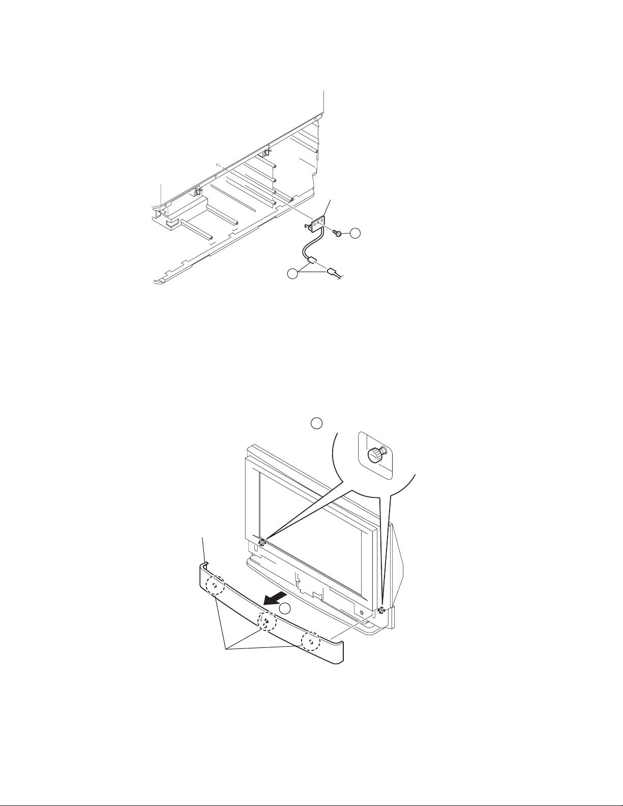
1-12.FRONT COVER ASSEMBLY REMOVAL
Front cover
assembly
1
1 Two ornamental screws
Four latches
1-12-1.REPLACING THE LAMP
For detailed instructions on replacing the lamp, see
Page 15 of the Operating Instructions manual.
PN 2-108-981-11
KF-42WE620/50WE620
2
15

1-13.H3 BOARD REMOVAL (KF-42WE620 ONLY)
H3 board
1
3
H3 bracket
KF-42WE620/50WE620
Disconnect two connectors
and one ground wire
1
Spring
plate
Two screws
(+BVTP 3x12)
2
1-14.H4 BOARD REMOVAL (KF-42WE620 ONLY)
H2 block assembly
Two screws
(+BVTP 4x16)
1
Disconnect two connectors
MS panel
KF-42WE620/50WE620
4
2
3
Two screws
(+BVTP 4x16)
4
H4 board
16

1-15.H3 AND H4 BOARD REMOVAL (KF-50WE620 ONLY)
r
Note:
To remove the H4 Board you need to remove the screws inside the Bottom Cabinet Assembly
H3 board
KF-42WE620/50WE620
Spring
plate
H3 bracket
Two screws
(+BVTP 3x12)
One screw
4
MS bracket
3
1-16.H2 BOARD REMOVAL
2
1
Disconnect two connectors
and one ground wire.
Disconnect two connectors
3
H4 board
Bottom cover assembly
KF-42WE620/50WE620
Two screws
(+BVTP 3x12)
H2 board
H2 bracket
1
Four screws
(+BVTP 4x16)
3
2
Disconnect one connecto
Light guide (LED)
17

1-17.H1 BOARD REMOVAL
Disconnect one connector
Screen mirror block assembly
4
3
H1 board
One screw (3x12)
H1 button
H1 bracket
Two screws
2
(+BVTP 4x16)
1 H1 bracket cap
Using tweezers gently detach two
H1 Bracket Caps
KF-42WE620/50WE620
1-18.SCREEN MIRROR BLOCK ASSEMBLY REMOVAL
Note: For the model 50WE620, remove the screws that secure
the reinfocement plates (R)/(L).
Screen mirror block assembly
Seven screws
3
(+BVTP 4x16)
1
Disconnect three connectors
KF-42WE620/50WE620
2
Four screws
(+BVTP 4x16)
18

SECTION 2: CIRCUIT ADJUSTMENTS
KF-42WE620/50WE620
2-1. SETTING THE SERVICE ADJUSTMENT
MODE
1. Standby mode (Power off).
2. Press the following buttons on the remote commander within a
second of each other:
Display
The following screen appears:
Channel
Category Name
3D-COMB 0 0 SERVICE
NRMD TV
WSL: xxx
Item Name Input Signal
F/A FLAG: xxxxxxxx
CBA FLAG: xxxxxxxx
Category Name
L001OUT 0 0 G
OCKPN
Item Name
TEMP 42DEG
LCD PJ ENGINE VER.0.026
9/11
EE2F
5
Item No.
Sound Volumne
Data
Item No.
<LCD PROJECTOR ENGINE>
Mode
Data
Power
+
2-2. SERVICE ADJUSTMENT MODE MEMORY
1. The SCREEN displays the item being adjusted.
2. Press 1 or 4 on the Remote Commander to select the item.
3. Press
4. Press
Note: Every time you press
3
or 6 on the Remote Commander to change the data.
2
or 5 on the Remote Commander to change the category.
2
(Category Up), Service Mode changes
in the order as shown below:
VERSION0
CCPM-1
CCPM-2
CCPM-3
CCPM-4
CCPM-5
CCPM-6
CCPM-7
CCPM-8
CCPM-9
CCPM-10
CH-SET
CCPS-1
CCPS-2
CCPS-3
CCPS-5
CCPS-6
CCPS-7
CCPS-8
CCPS-10
DCP-INT
DCP-OSD
DCP-BLK
DCP-ADJ1
DCP-ADJ2
DCP-USER
DCP-AVP
USR-NR
CXA2171
AP
DLBY
MID1
MID2
MID3
MID4
MID5
MID6
MID7
MID8
MID9
SNNR
SNSS
DRCVR
CCD
D9671-1
D9671TPN
D9671CUR
D9671TG1
D9671TG2
D9671CSC
A7001R
A7001G
A7001B
SH SET
H POS SHI
TEMP
OSD-E
OPTION-E
FAN-CTL
GB RGB
KF-42WE620/50WE620
CCPS-4
AK4524
5. To go back to the most recently saved value
D9671PIC
0
then
OPTION-E
ENTER
ID
to read
the memory.
6. Press
MUTING
then
ENTER
to write into memory.
7. When you want to exit Service Mode, turn the power off.
Note: Press “8” then “[ENTER]” on the remote commander to set
the shipping conditions or turn set off and on to exit.
19
2-3. MEMORY WRITE CONFIRMATION METHOD
1. After adjustment, pull out the plug from the AC outlet, then replace the plug in the AC outlet again.
2. Turn the power switch ON and set to Service Mode.
3. Call the adjusted items again to confi rm they were adjusted.
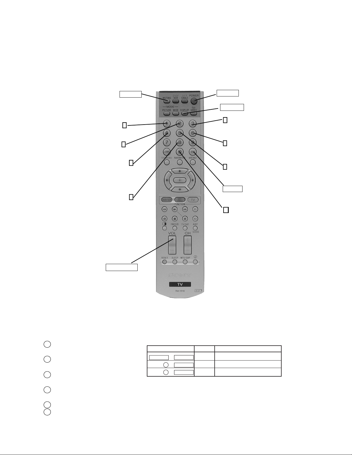
2-4. REMOTE ADJUSTMENT BUTTONS AND INDICATORS
KF-42WE620/50WE620
MUTING
(Enter into
memory)
Adjustment
Item up
Adjustment
Category up
Adjustment
Item down
User control goes to the
standard state (Shipping
Conditions)
1
2
4
8
POWER
(Service Mode)
DISPLAY
(Service Mode)
3
Data up
6
Data down
5
Adjustment
category down
ENTER
(Enter into
memory)
0
Read data
from NVM
VOLUME (+)
(Service Mode)
FUNCTION OF KEYS ON COMMANDER
• 1 : Changes adjustment item.
(item No. moves up)
• 4 : Changes adjustment item.
(item No. moves down)
• 2 : Changes adjustment category.
(category moves up)
• 5 : Changes adjustment category.
(category moves down)
• 3 : Changes data value. (up)
• 6 : Changes data value. (down)
RM-Y916
Commander Function
Button Mode Description
MUTING + ENTER WRITE Writes data to NVM.
0 + ENTER READ Reads data from NVM.
8 + ENTER RESET Set the shipping condition.
(Use only to reset to
shipping standards)
KF-42WE620/50WE620
20

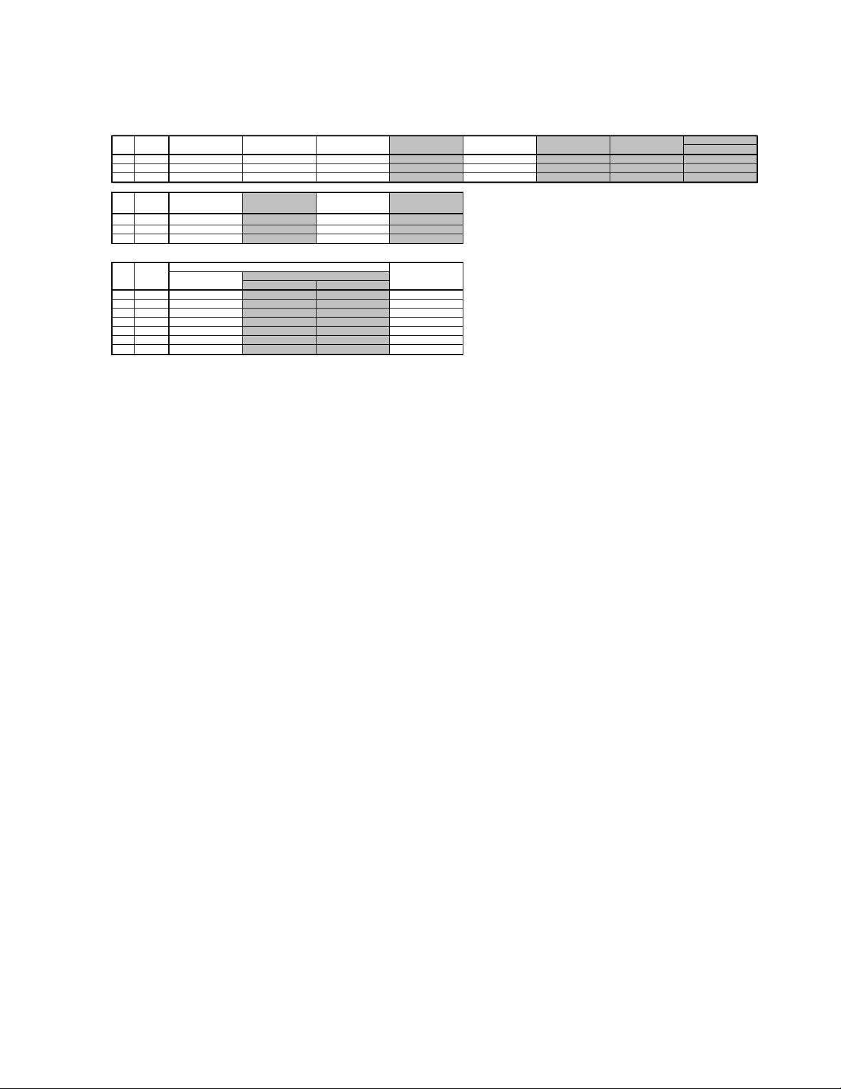
2-5. SERVICE DATA
CCPM-1
No. Nam
e
0SHPC *1
1FUP2 *1
2YNR *1
3CNR *1
4SSHP *1
5YEQ *1
6SHF0 *1
7SECA *2
8YCDL *3
9YLEV *3
10 CLEV *3
11 SHU
E
*4
12 CEQ *4
13 CBP
F
*4
14 CBPA *4
15 KILV *4
16 APGA *4
17 NCOM *4
Standards *1
Vivid Standar
dPro
Reserve
d
Vivid Standar
dPro
Reserve
d
0SHPC11101110
1FUP200000000
2YNR00000000
3CNR00000000
4SSHP21175557
5YEQ31131113
6SHF011111111
Vivid Standar
dPro
Reserve
d
Vivid Standar
dPro
Reserve
d
0SHPC00000000
1FUP200000000
2YNR00000000
3CNR00000000
4SSHP77777777
5YEQ33333333
6SHF011111111
Vivid Standar
dPro
Reserve
d
Vivid Standar
dPro
Reserve
d
0SHPC00000000
1FUP200000000
2YNR00000000
3CNR00000000
4SSHP77777777
5YEQ33333333
6SHF011111111
Vivid Standar
dPro
Reserve
d
Vivid Standar
dPro
Reserve
d
0SHPC00000000
1FUP200000000
2YNR00000000
3CNR00000000
4SSHP77777777
5YEQ33333333
6SHF011111111
Vivid Standar
dPro
Reserve
d
Vivid Standar
dPro
Reserve
d
0SHPC00000000
1FUP200000000
2YNR00000000
3CNR00000000
4SSHP77777777
5YEQ33333333
6SHF011111111
Vivid Standar
dPro
Reserve
d
0SHPC0000
1FUP20000
2YNR0000
3CNR0000
4SSHP7777
5YEQ3333
6SHF01111
Vivid Standar
dPro
Reserve
d
Vivid Standar
dPro
Reserve
d
0SHPC00000000
1FUP200000000
2YNR00000000
3CNR00000000
4SSHP77777777
5YEQ33333333
6SHF011111111
i.LINK(ex DV)for XBR(BS/CS/i.LINK(ex DV))
480i(ex DV Format)(480i) 480pNo. Name
DVI(AVM(RG B)/DVI)
VGA(VGA/O THER)
480
i
Component(AVM(YC bCr))
1080
i
720p
480p
DVI(AVM(RG B)/DVI)
1080
i
720p
DVI(AVM(RG B)/DVI)
Component(AVM(YC bCr))
480
i
480p
UV Video
Functionalit
y
Data Remarks
No. Name
No. Name
No. Name
No. Name
No. Name
No. Name
KF-42WE620/50WE620
KF-42WE620/50WE620
21

KF-42WE620/50WE620
dPro
d
dPro
d
dPro
dPro
d
dPro
d
dPro
d
dPro
d
dPro
d
dPro
dPro
d
dPro
d
dPro
d
dPro
e
o
i
i
i
i
i
r
i
i
r
i
i
i
r
i
i
r
No. Name
0SHPC00000000
1FUP200000000
2YNR00000000
3CNR00000000
4SSHP77777777
5YEQ33333333
6SHF011111111
No. Name
0SHPC00000000
1FUP200000000
2YNR00000000
3CNR00000000
4SSHP77777777
5YEQ33333333
6SHF011111111
No. Name
0SHPC00000000
1FUP200000000
2YNR00000000
3CNR00000000
4SSHP77777777
5YEQ33333333
6SHF011111111
Name
No.
0SHPC00000000
1FUP200000000
2YNR00000000
3CNR00000000
4SSHP77777777
5YEQ33333333
6SHF011111111
No. Name
0SHPC0000
1FUP20000
2YNR0000
3CNR0000
4SSHP7777
5YEQ3333
6SHF01111
No. Name
0SHPC00000000
1FUP200000000
2YNR00000000
3CNR00000000
4SSHP77777777
5YEQ33333333
6SHF011111111
No. Name
0SHPC00000000
1FUP200000000
2YNR00000000
3CNR00000000
4SSHP77777777
5YEQ33333333
6SHF011111111
Standards *2
No. Nam
7SECA 10 10
No. Name
7SECA000000000
No. Name
7SECA000000
No. Name
7SECA00000
No. Name
7SECA0000
Vivid Stand ar
i.LINK for XBR (BS/CS/i. LINK(ex D V))
Vivid Stand ar
Vivid Stand ar
Vivid Stand ar
Vivid Stand ar
Vivid Stand ar
Vivid Stand ar
UV Vide
480
480i(ex DV) 480p 1080
480
DATA(ADD) DATA(INDEPEND ENT)
480
1080
480i(DV Format)Lowe
480
1080
ATSC(DTT/ATSC)
Lowe
STILL(1080i)(480i)
MOVIE(LOW) (480i) MOVIE(HIGH) OTHER
Component(AVM(YCbCr)) DVI(AVM(RGB)/DVI)
480p 1080
i.LINK(ex DV) for XBR(BS/CS/i.LINK(ex DV))
480p 1080
OTHER 480
ATSC(DTT/AT SC)
i.LINK(ex DV)for XBR(BS/CS/i.LINK(ex DV))
Reserve
Mild Vivid Sta ndar
ATSC for XB R(DTT/ATSC)
Reserve
ATSC for XB R(DTT/ATSC)
Reserve
Mild
MS for XB R(DATA(ADD))
Reserve
MS for XB R(DATA(INDEPENDENT))
Reserve
720p 480
720p Lowe
720p Lowe
OTHER
Vivid Standar
Vivid Standar
Vivid Standar
Vivid Standar
Vivid Standar
MOVIE(CONT -PANEL) (OTHER)
i.LINK (DV)
720p
i.LINK (DV)
480p
720p
480p 1080
Reserve
Reserve
Reserve
Reserve
Reserve
Mild
720p V GA(VGA/OTHER)
KF-42WE620/50WE620
22
KF-42WE620/50WE620
E
F
t
Standards *3
No. Name
8YCDL88777777
9 YLEV 175 175 175 175 175 175 175 175
10 CLEV 97 97 185 185 185 185 185 185
No. Name
8YCDL7777
9 YLEV 175 175 175 175
10 CLEV 185 185 185 185
Standards *4
No. Name
11 SHU
12CEQ3110
13 CBP
14CBPA0110
15KILV2222
16APGA0000
17NCOM0000
UV Video Component (not 480i)
Component (480i)
UV(GR O FF)
ATSC for XBR (480i)
(AVM(Y/Cb/Cr))
UV
7777
3220
GCR ON GCR OFF
DVI (480i)
(AVM(RGB)/DVI)
GR ON Vide o
ATSC for XBR (no
480i)(AVM(Y/Cb/Cr))
i.LINK (not 480i and
ex DV) for XBR
DVI (not 480i)
(AVM(RGB)/DVI)
i.LINK (480i and ex
DV) for XBR
i.LINK (DV)
MS for XBR
(DTT/ATSC)
KF-42WE620/50WE620
23

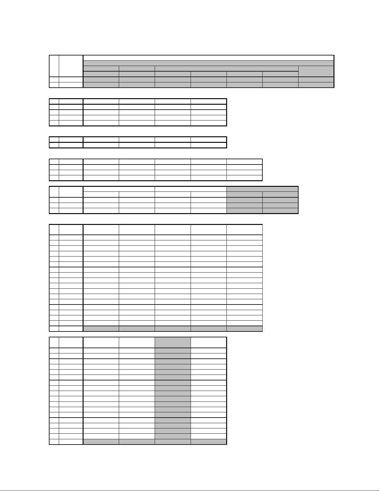
CCPM-2
A
I
T
A
I
T
KF-42WE620/50WE620
Functionality
No. Name
0PACK *1
1CLPP *2
2 SSEP *2
3CLPG *2
4CLP
5AFCV *2
6 HSSL *2
7 VSSL *2
8STIP *2
9SYLP *2
10 SYF
11 AFCG *2
12 LOWG *2
13 AFCM *2
14 LOCO *2
15 HICO *2
16 CDM1 *2
17 CDM2 *2
18 CDM3 *2
19 BGPS *2
20 VINT *2
21 HSPO *2
22 MVSW *2
23 MVC
24 MVHC *2
25 CLAL *2
26 ADPS *2
27 CLGA *2
28 YTRP *2
29 CT RP *2
30 CROF *2
31 SDLP *2
32 ROM2 *2
Standards *1
No. Name UV Video1 Video2 Video3 Video4
0PACK04444
Data Remarks
*2
*2
*2
No. Name
0PACK56785678
No. Name
0PACK5678567813
Standards *2
No. Name PACK=0 PACK=1 PACK=2 PACK=3 PACK=4 PACK=5 PACK=6 PACK=7 PACK=8
1CLPP282828282828282828
2SSEP000000000
3CLPG000000000
4CLP
5AFCV111111111
6HSSL222200033
7VSSL222222233
8STIP2 22222222
9SYLP000000000
10 SYF
11AFCG112201111
12 LOWG 0 0 0 0 0 0 0 0 0
13AFCM000000000
14LOCO000000000
15HICO000000000
16CDM1222222222
17CDM2000000000
18CDM3000000000
19 BGPS 10 10 10 10 10 10 10 10 10
20 VINT 7 7 7 7 7 7 7 3 7
21HSPO777777777
22MVSW222222222
23 MVC
24MVHC444444444
25CLAL000000000
26ADPS0 00000000
27CLGA222222222
28YTRP1 11110000
29CTRP111110000
30CROF111111111
31SDLP111110000
32ROM2000000000
KF-42WE620/50WE620
480i 480p 1080i 720p 480i 480p 1080i 720p
480i 480p 1080i 720p 480i 480p 1080i 720p VGA/OTHER
000000000
101011000
777777777
Video5(COMPONENT1)
i.LINK/ATSC/MS for XBR(AVM(YCbCr))
Video6(COMPONENT2)
DVI(AVM(RGB)/DVI)
24

No. Name PACK = 9 PACK = 10 PACK = 11 PACK = 12 PACK = 13 PACK = 14 PACK = 15
A
I
T
K
F
R
H
L
L
F
L
P
1CLPP28282828282828
2SSEP0000000
3CLPG0000000
4CLP
5AFCV111 1111
6HSSL1111022
7VSSL2222222
8STIP2222222
9SYLP0000000
10 SYF
11AFCG1122123
12 LOWG 0 0 0 0 0 1 3
13AFCM0000000
14LOCO0000000
15HICO0000000
16CDM12222222
17CDM20000000
18CDM30000000
19 BGPS 10 10 10 10 10 10 10
20 VINT 7 7 7 7 7 7 7
21HSPO7777777
22MVSW2222222
23 MVC
24 MVHC 4 4 4 4 4 4 4
25CLAL0000000
26ADPS0 000000
27CLGA2222222
28 YTRP 1 1 1 1 0 1 1
29CTRP1111011
30 CROF 1 1 1 1 1 1 1
31SDLP1111011
32ROM20000000
0000000
1010011
7777777
KF-42WE620/50WE620
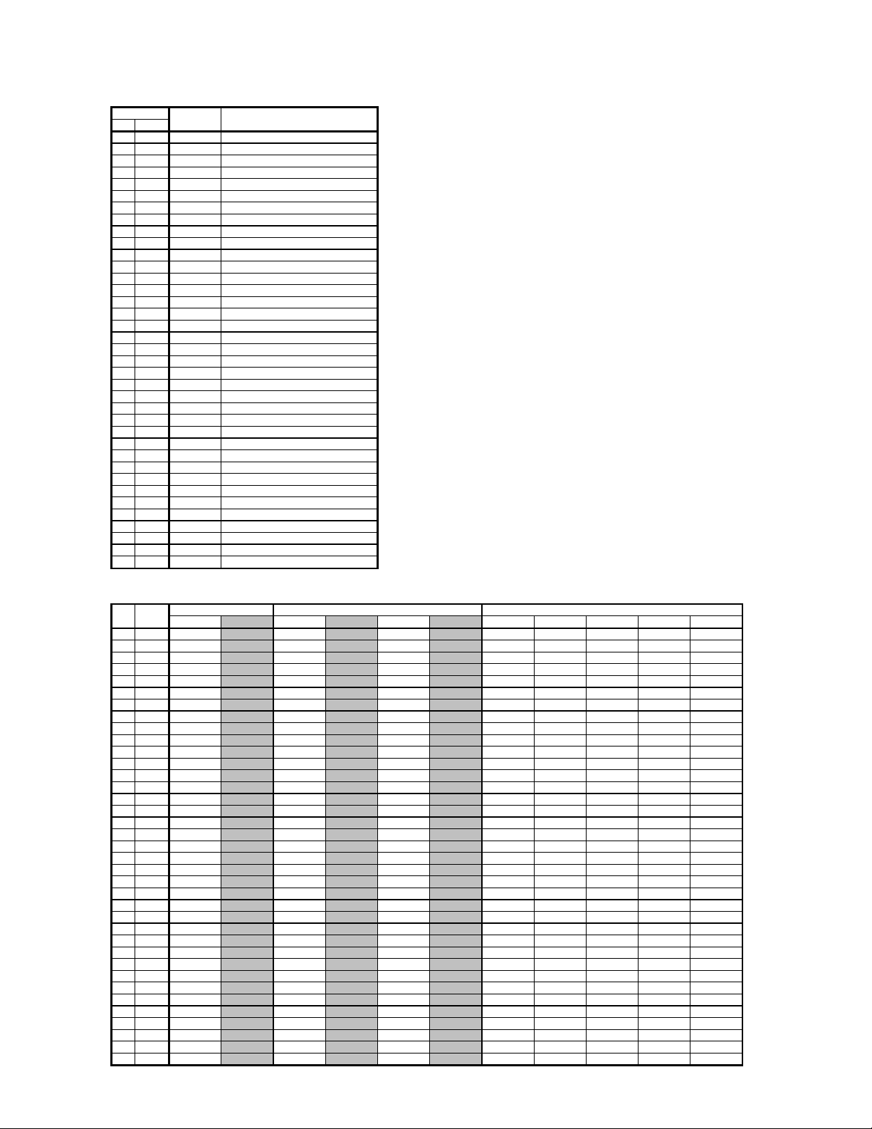
CCPM-3
Functionality
No. Name
0AD1E 0
1APED *1
2 AAT
3 AHLD *2
4 AARE *2
5 AHIS *2
6 DCTR *1
7 DCTC *3
8ID1W *4
9WSSO *4
10 SLIC *4
11 AWO
12 UPA
13 UPT
14 X149 *5
15 DMST *5
16 INST *5
17 UPR
18 OFS
19 SLO
20 FR43 *5
21 FRWI *5
22 FRTI *5
23 LPF
24 4CNT *5
25 REF
26 REFM *5
27 AWSN *5
28 AWRE *5
Data Remarks
*2
*5
*5
*5
*5
*5
*5
*5
*5
KF-42WE620/50WE620
25

KF-42WE620/50WE620
Standards *1
AD1E = 1 Or MULTI(TWIN,FAVORITES)
No. Name
1APED2101231
6DCTR2101231
Vivid Standard
BLK Correction Off BLK CorrectionLBLK CorrectionMBLK Correction H
480i(RF/Video/Component480i)
Pro
Reserved
AD1E = 1 Or MULTI(TWIN,FAVORITES)
No. Name
Vivid Standard
1APED2101231
6DCTR2101231
BLK Correction Off BLK CorrectionLBLK CorrectionMBLK Correction H
480p
Pro
Reserved
AD1E = 1 Or MULTI(TWIN,FAVORITES)
No. Name
Vivid Standard
BLK Correction Off BLK Correction L BLK Correction M B LK Correction H
1080i/60
Pro
Reserved
1APED2101231
6DCTR2101231
AD1E = 1 Or MULTI(TWIN,FAVORITES)
No. Name
Vivid Standard
BLK Correction Off BLK Correction L BLK Correction M B LK Correction H
720p/60
Pro
Reserved
1APED2101231
6DCTR2101231
AD1E = 1 Or MULTI(TWIN,FAVORITES)
No. Name
Vivid Standard
BLK Correction Off BLK Correction L BLK Correction M B LK Correction H
576i
Pro
Reserved
1APED3201231
6DCTR3201231
AD1E = 1 Or MULTI(TWIN,FAVORITES)
No. Name
Vivid Standard
BLK Correction Off BLK Correction L BLK Correction M B LK Correction H
576p
Pro
Reserved
1APED3201231
6DCTR3201231
AD1E = 1 Or MULTI(TWIN,FAVORITES)
No. Name
Vivid Standard
BLK Correction Off BLK Correction L BLK Correction M B LK Correction H
1080i/50
Pro
Reserved
1APED3201231
6DCTR3201231
KF-42WE620/50WE620
26
KF-42WE620/50WE620
K
F
R
H
L
L
F
L
P
F
R
H
L
L
F
L
P
AD1E = 1 Or MULTI(TWIN,FAVORITES)
No. Name
Vivid Standard
BLK Correction Off BLK Correction L BLK Correction M B LK Correction H
720p/50
Pro
Reserved
1APED3201231
6DCTR3201231
Standards *2
No. Name
2 AAT
APED = 0 APED = 1 APED = 2 APED = 3
2222
3 AHLD 2 2 2 2
4 AARE 2 2 2 2
5 AHIS 0 0 0 0
Standards *3
No. Name
DCTR = 0 DCTR = 1 DCTR = 2 DCTR = 3
7 DCTC 2 2 2 2
Standards *4
No. Name UV Video1 Video2 Video3 Video4
8ID1W11111
9WSSO00000
10 SLIC 5 5 5 5 5
No. Name
Video5(COMPONENT1) Video6(COMPONENT2)
480i 480p 480i 480p 480i 480p
i.LINK/ATSC for XBR(AVM(YCbCr))
8ID1W111111
9WSSO000000
10SLIC555555
Standards *5
No. Name UV Video1 Video2 Video3 Video4
11 AWO
12 UPA
13 UPT
00000
00000
00000
14 X149 0 0 0 0 0
15DMST11111
16 INST 0 0 0 0 0
17 UPR
18 OFS
19 SLO
11111
00000
00000
20 FR43 2 2 2 2 2
21FRWI22 222
22FRTI22222
23 LPF
11111
24 4CNT 1 1 1 1 1
25 REF
11111
26 REFM 5 5 5 5 5
27AWSN00000
28 AWRE 0 0 0 0 0
No. Name
11 AWO
12 UPA
13 UPT
14 X149 0 0 0 0
15DMST1111
16 INST 0 0 0 0
17 UPR
18 OFS
19 SLO
20 FR43 2 2 2 2
21FRWI22 22
22FRTI2222
23 LPF
24 4CNT 1 1 1 1
25 REF
26 REFM 5 5 5 5
27AWSN0000
28 AWRE 0 0 0 0
KF-42WE620/50WE620
Video5
480i(COMPONENT1 480i)
Video6
480i(COMPONENT2 480i)
i.LINK/ATSC for XBR 480i
(AVM(YCbCr) 480i)
DVI 480i(AVM(RGB)
480i)
0000
0000
0000
1111
0000
0000
1111
1111
27
CCPM-4
W
L
W
L
KF-42WE620/50WE620
Functionality
No. Name
0CLKS *1
1REFC *1
2SYMD *1
3SIFM *1
4DTO1 *1
5DTO2 *1
6DTO3 *1
7PIX1 *1
8PIX2 *1
9VLN1 *1
10 VLN2 *1
11 SYSC *1
12 DSPC *1
13 PLLD *1
14 PLLR *1
15 DCLP *1
16 DCON *1
17 CO2P *1
18 CONV *1
19 HO2O *1
20 BLKM *1
21 OSDL *1
22 OSDR *1
23 CO2O *1
24 COLS *1
25 VFRQ *1
26 PLLS *1
27 PIF
28 PIBW *1
29 PLL4 *1
30 CDAD *1
31 CDAS *1
32 PLD1 *1
33 PLTS *1
34 PLO
35 YRND *1
36 CRND *1
Data Remarks
*1
*1
Standards *1
No. Name
0CLKS000 00000000
1REFC1111111 1111
2SYMD0000558 8888
3SIFM00000 002342
4DTO16363636363636363636363
5 DTO2 254 254 254 254 254 254 254 254 254 254 254
6DTO38686868686868686868686
7PIX10000000 0000
8PIX20000000 0000
9VLN1000 00000000
10 VLN2 0 0 0 0 0 0 0 0 0 0 0
11SYSC11111110000
12DSPC33333331111
13PLLD00000000000
14PLLR11111111111
15DCLP22222222222
16 DCON 0 0 0 0 0 0 0 0 0 0 0
17CO2P00000000000
18CONV00000000000
19 HO2O 1 1 1 1 1 1 1 0 0 0 0
20BLKM11111111111
21 OSDL 3 3 3 3 3 3 3 3 3 3 3
22 OSDR 1 1 1 1 1 1 1 1 1 1 1
23CO2O11111110000
24COLS00000000000
25VFRQ33333333333
26PLLS00000000000
27 PIF
28 PIBW 0 0 0 0 0 0 0 0 0 0 0
29PLL400000000000
30CDAD00000000000
31CDAS00000000000
32PLD100000000000
33PLTS00000000000
34 PLO
35 YRND 1 1 1 1 1 1 1 1 1 1 1
36CRND11111111111
UV
3-D 2-D 3-D 2-D YC YC 480i 480p 1080i 720p VGA(DVI)
00000000000
00000000000
Video Component, ATSC, DVI
KF-42WE620/50WE620
28

KF-42WE620/50WE620
W
L
No. Name
0CLKS055 5504
1REFC1 111111
2 SYMD 5 14 14 14 14 8 12
3SIFM00234 315
4DTO163636363636363
5 DTO2 254 254 254 254 254 254 254
6DTO386868686868686
7PIX1000000255
8PIX200000015
9VLN1000 0000
10 VLN2 0 0 0 0 0 0 64
11SYSC1100000
12DSPC3200010
13PLLD0000000
14PLLR1211111
15 DCLP 2 2 2 2 2 2 2
16 DCON 0 0 0 0 0 0 0
17CO2P0000000
18 CONV 0 0 0 0 0 0 0
19 HO2O 0 0 0 0 0 0 0
20BLKM1111111
21 OSDL 3 3 3 3 3 3 3
22 OSDR 1 1 1 1 1 1 1
23CO2O0000000
24COLS0000000
25VFRQ3333333
26PLLS0000000
27 PIF
28PIBW0000000
29PLL40000000
30CDAD0000000
31 CDAS 0 0 0 0 0 0 0
32PLD10000000
33PLTS0000000
34 PLO
35 YRND 1 1 1 1 1 1 1
36CRND1111111
BS/DTT
YC
0000000
0000000
480i 480p 1080i 720p
BS/DTT
MS/CNM for
XBR
MS/CNM for
WE to CCPS
CCPM-5
No. Name
0NSS 8 8
1 TESS 0 0
2 NSC 15 15
3NSV 1 1
4STDH 2 2
5SHH 1 1
UV Video
DataFunctionality
Remarks
KF-42WE620/50WE620
29

CCPM-6
T
F
L
T
L
L
W
KF-42WE620/50WE620
Functionality Data
No. Name
0MC1 4 4
1MC2 3 3
2CR1 1 1
3CR2 1 1
4CR3 0 0
5CR4 1 1
6CCR 2 2
7CHED 2 2
8CVED 3 3
9CR5 4 4
10 YFL
11 C3LE 1 1
12 YMFH 3 3
13 YMFV 1 1
14 F2SW 0 0
15 MO1 15 15
16 MO2 3 3
17 MNNR 1 1
18 DTH 2 2
19 DTV 2 2
20 DT2D 2 2
21 DTHP 3 3
22 DTCR 4 4
23 D2FC 3 3
24 D2
25 D2F2 1 1
26 D2F
27 DC 0 0
28 CVF
29 HC2F 1 1
30 MNSW 0 0
31 MDYB 0 0
32 LCBP 2 2
33 BPSE 1 1
34 CR2H 0 0
35 IMPR 3 3
36 IMPS 1 1
37 IMPL 0 0
38 PLP
39 MDYE 3 3
40 PLCL 1 1
41 BPL2 1 1
42 HP
43 CVFP 0 0
44 BPL3 7 7
45 D2F3 2 2
46 LPS
47 LCR 1 1
48 F2CR 1 1
49 YIR 1 1
50 MOMO 0 0
UV Video
44
99
00
33
11
11
11
Remarks
KF-42WE620/50WE620
30
 Loading...