

Sony KE-MR42M1, KE-MR50M1 Service Manual
MODIFICATION HISTORY
想了解更多的资料请登陆图纸手册交流网站
(http://schematic.5d6d.com)
MODEL NAME : KE-MR42M1/MR50M1
SERVICE MANUAL
PARTS No. : 9-978-764-02
No. DATA CONTENTS
* Blue characters are linking.
1
2004. 7 S.5 EXPLODED VIEWS totally revised due to addition of PDM-4200/5000
doubllscan display panel.
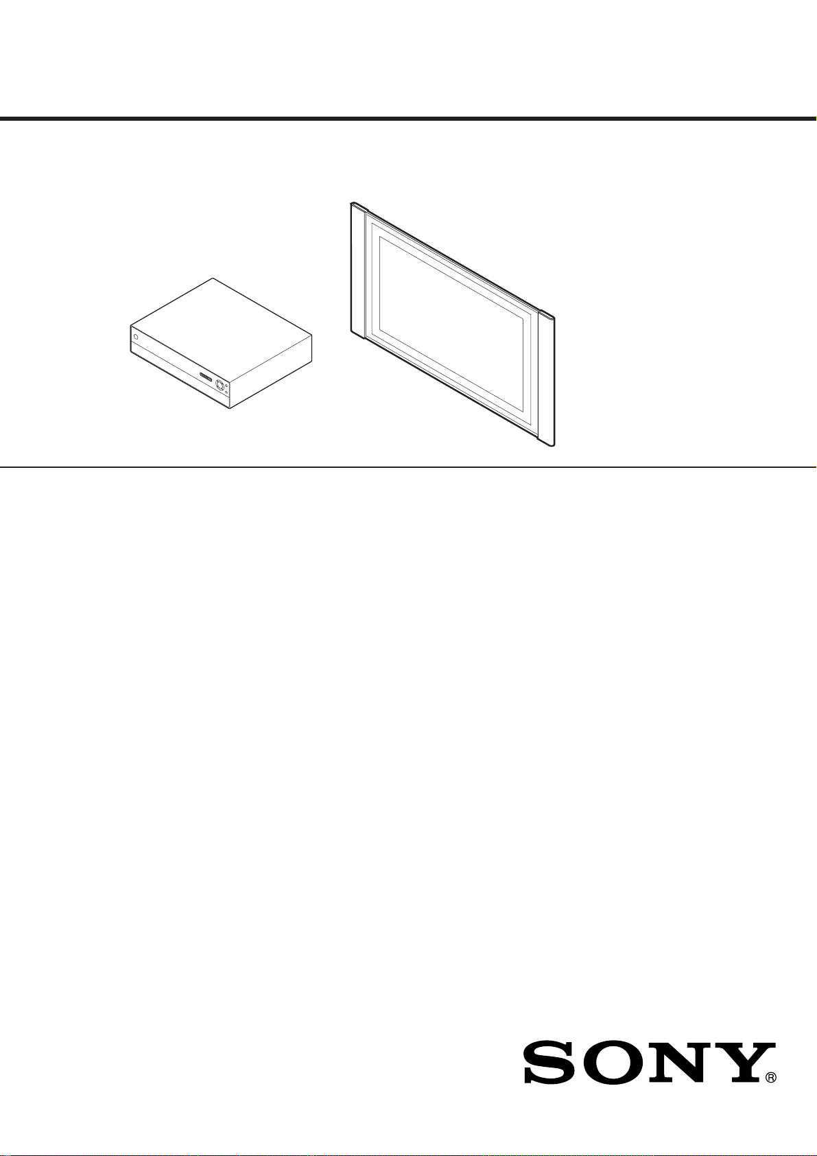
KE-MR42M1/MR50M1
想了解更多的资料请登陆图纸手册交流网站
(http://schematic.5d6d.com)
SERVICE MANUAL
MBT-MR1C PDM-4200/5000
SPECIFICATIONS
Chinese Model
MR1 CHASSIS
KE-MR42M1/MR50M1 (Common Items)
Media Receiver Unit (MBT-MR1C)
Power Requirement: 220 V AC; 50 Hz
Power Consumption: 27 W
Standby Power Consumption: 0.6 W (power switch off)
Dimensions (w x h x d):
Approx. 430 x 105 x 360 mm
Weight: Approx. 6 kg
KE-MR42M1 only
Display Unit (PDM-4200)
Power Requirement: 100-240V AC; 50/60 Hz
Screen Size: 42inches
Approx. 107 cm measured
diagonally
Display Resolution:
1024 dots (horizontal) x 768 lines
(vertical)
Power Consumption: 460 W
Standby Power Consumption: 0.6W
Dimensions (w x h x d):
Approx. 1,352 x 720 x 102 mm
Weight: Approx. 39 kg
KE-MR50M1 only
Display Unit (PDM-5000)
Power Requirement: 100-240V AC; 50/60 Hz
Screen Size: 50inches
Approx. 127 cm measured
diagonally
Display Resolution:
1365 dots (horizontal) x 768 lines
(vertical)
Power Consumption: 540W
Standby Power Consumption: 0.6W
Dimensions (w x h x d):
Approx. 1,573 x 856 x 108 mm
Weight: Approx. 53 kg
Panel System:
Plasma Display Panel
TV system:
D/K, B/G, I
Colour system:
PAL, NTSC, SECAM
Aerial:
75 ohm external terminal for VHF/UHF
Channel Coverage:
VHF: C1-C12
UHF: C13-C57
CATV: Z1-Z39
FLAT PANEL COLOR TELEVISION

Rear Terminals:
想了解更多的资料请登陆图纸手册交流网站
(http://schematic.5d6d.com)
1
S video input (4-pin mini DIN):
Y: 1 Vp-p, 75-ohms unbalanced, sync
negative
C: 0.286 Vp-p (Burst signal), 75 ohms
video input (phono jack):
1 Vp-p, 75-ohms unbalanced, sync
negative
audio input (phono jacks):
500 m Vrms (100% modulation),
Impedance: 47 kilo ohms
2
video input (phono jack):
1 Vp-p, 75-ohms unbalanced, sync
negative
audio input (phono jacks):
500 m Vrms (100% modulation),
Impedance: 47 kilo ohms
3
video input (phono jack):
1 Vp-p, 75-ohms unbalanced, sync
negative
audio input (phono jacks):
500 m Vrms (100% modulation),
Impedance: 47 kilo ohms
4
Y: 1 Vp-p, 75 ohms, 0.3V negative sync
B: 0.7 Vp-p, 75 ohms
P
: 0.7 Vp-p, 75 ohms
R
P
audio input (phono jacks)
500 m Vrms (100% modulation),
Impedance: 47 kilo ohms
5
Y: 1 Vp-p, 75 ohms, 0.3V negative sync
B: 0.7 Vp-p, 75 ohms
P
: 0.7 Vp-p, 75 ohms
R
P
audio input (phono jacks)
500 m Vrms (100% modulation),
Impedance: 47 kilo ohms
5555
SUB WOOFER: phono jack
: audio outputs (Left/Right) - phono jacks
5555
CENTRE SPEAKER IN:
Max. 180W (6-ohms)
CTRL S: minijack
AV MOUSE: minijack
Front Terminals:
6
S video input (4-pin mini DIN):
Y: 1 Vp-p, 75-ohms unbalanced, sync
negative
C: 0.286 Vp-p (Burst signal), 75 ohms
video input (phono jack):
1 Vp-p, 75-ohms unbalanced, sync
negative
audio input (phono jacks):
500 m Vrms (100% modulation),
Impedance: 47 kilo ohms
headphones jack
i
PC
PC Input (15-Dsub)
G: 0.7 Vp-p, 75 ohms, non Sync on Green
B: 0.7 Vp-p, 75 ohms, non Sync on Green
R: 0.7 Vp-p, 75 ohms, non Sync on Green
HD:1-5 Vp-p
VD: 1-5 Vp-p
PC
PC audio input: minijack
Memory Stick Slot
Sound Output:
15W x 2
Accessories supplied:
• One Remote Controller (RM-972)
• Two size AAA batteries (R03 type)
• One Display Interface Cable
• One Coaxial Cable
• One AV Mouse
• One Cleaning cloth
• One Mains plug holder
Other features:
• Sleep Timer
PC Input Timing:
Input signal frequency
Horizontal: 15.6 - 90 kHz
Vertical: 48 - 85 Hz
Maximum Resolution: 1600 dots x 1200 lines
KE-MR42/50M1(CH) 2
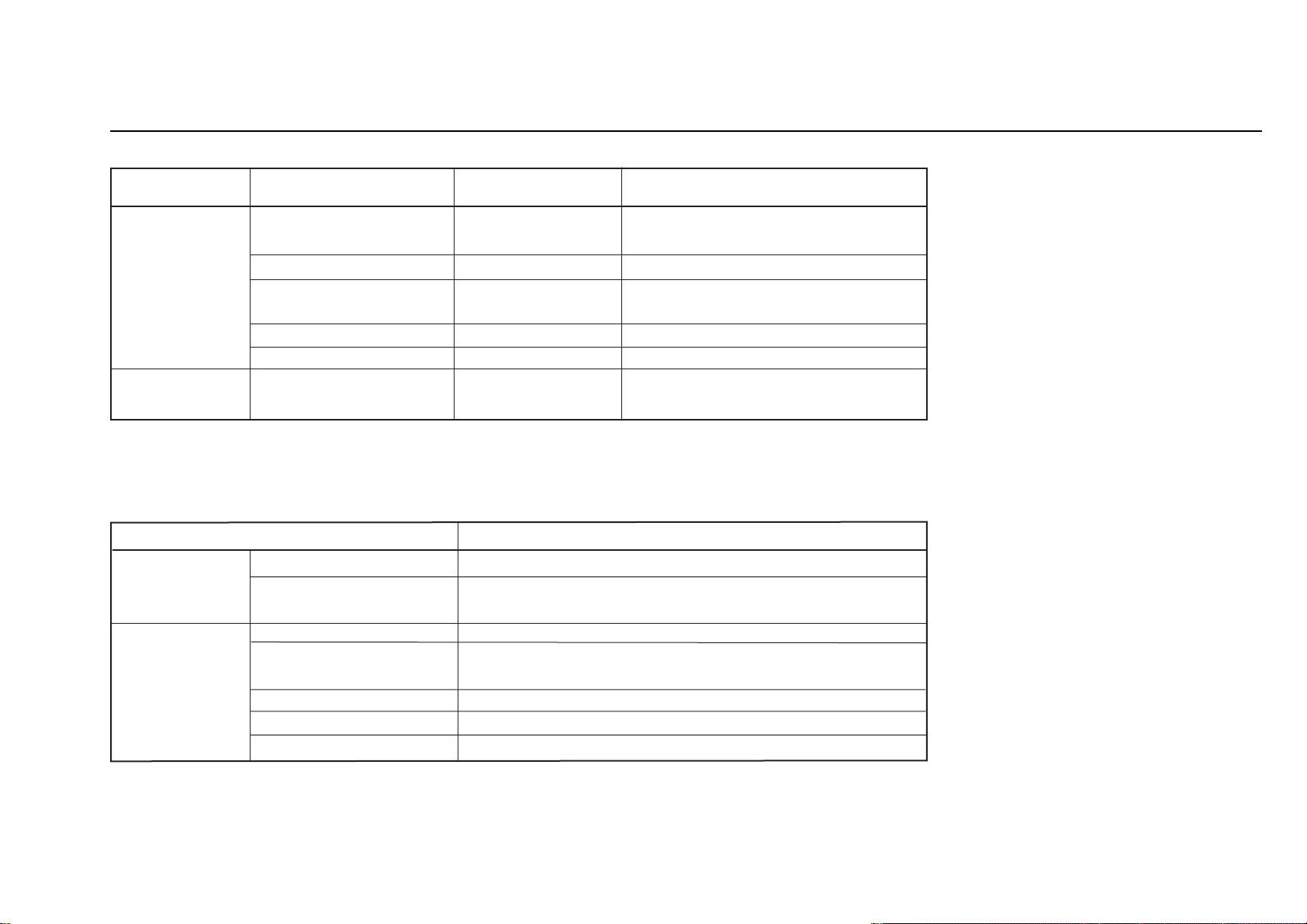
DIAGNOSIS (Reliability Self Diagnostic Display Specifications for MEDIA RECEIVER)
想了解更多的资料请登陆图纸手册交流网站
(http://schematic.5d6d.com)
The abnormal conditions are indicated by the following LED flashes.
LED Status MEDIABOX PANEL
POWER/STBY • ⇔ • flashes alternately - PANEL ALARM
(Not available for re-start)
Flashes (1Hz) - Defective for cable connection
•Flashes four times - Defective for power voltage of fan,
fan protection
•Flashes six times +3.3V malfunction Power protection on G board detected
•Flashes nine times PANEL malfunction TIMER Flashes (1Hz) Defective for cable -
connection
This unit has the following self diagnostic function. Refer to this table to
identify a defective point in case of any malfunction.
Problem Symptom
Mediabox Digital 3.3V malfunction Shut down when Digital 3.3V becomes equal or under 0V.
Defective for cable The both White and Black interface cables are not connected
connection with the panel.
Panel PANEL ALARM
Defective for cable The both White and Black interface cables are not connected
connection with the MEDIABOX.
Fan malfunction
Power protector operation
*Operation count is based on WDT.
*For flashes, the Power/Standby LED flashes in red.
*The flash period is based on the reliability standard.
KE-MR42/50M1(CH) 3

TABLE OF CONTENTS
想了解更多的资料请登陆图纸手册交流网站
(http://schematic.5d6d.com)
Section Title Page Section Title Page
1. DISASSEMBLY ............................................................. 1-1
1-1. Display Unit (PDM-4200/5000) ............................................. 1-1
1-1-1. Rear Cover Removal .................................................. 1-1
1-1-2. K and F Boards Removal ........................................... 1-2
1-1-3. P Board Removal ....................................................... 1-3
1-1-4. G and F2 Boards Removal ......................................... 1-4
1-1-5. R1 Board Removal ..................................................... 1-5
1-1-6. R2 Board Removal ..................................................... 1-6
1-2. Media Receiver Unit (MBT-MR1C) ....................................... 1-7
1-2-1. Panel and Covers Removal ........................................ 1-7
1-2-2. G2, A, and MS Boards Removal ............................... 1-8
1-2-3. TU Board Removal .................................................... 1-9
1-2-4. U Board Removal ...................................................... 1-10
1-2-5. H2 Board Removal ..................................................... 1-11
1-2-6. H5 Board Removal .................................................... 1-12
1-2-7. MSX Board Removal ................................................. 1-13
1-2-8. H1 Board Removal .................................................... 1-14
1-2-9. H4 Board Removal ..................................................... 1-15
2-1-3. AD Adjustment of Component (other 15k)
System ........................................................................ 2-1
2-1-4. AD Adjustment of CVBS Video (NTSC)
System ........................................................................ 2-2
2-1-5. AD Adjustment of CVBS Video (PAL)
System ........................................................................ 2-3
2-1-6. AD Adjustment of CVBS Video (PAL 60)
System ........................................................................ 2-3
2-1-7. AD Adjustment of YC Video (NTSC)
System ........................................................................ 2-4
2-1-8. AD Adjustment of YC Video (PAL)
System ........................................................................ 2-5
2-1-9. AD Adjustment of YC Video (PAL 60)
System ........................................................................ 2-5
2-1-10. AD Adjustment of Component (15k)
System ........................................................................ 2-6
2-2. VS, VD Voltage Adjustment (PDM-4200/5000) .................... 2-7
2-3. White Balance Adjustment (PDM-4200/5000) ....................... 2-8
2. ADJUSTMENTS ............................................................ 2-1
2-1. Readjustment of A/D Converter and Video Coder
Calibration (MBT-MR1C) ...................................................... 2-1
2-1-1. Adjustment Preparation .............................................. 2-1
2-1-2. AD Adjustment of RGB System ................................ 2-1
3. TROUBLESHOOTING ................................................. 3-1
3-1. Display Unit (PDM-4200/5000) .............................................. 3-1
3-2. Media Receiver Unit (MBT-MR1C) ....................................... 3-2
KE-MR42/50M1(CH) 4

Section Title Page Section Title Page
想了解更多的资料请登陆图纸手册交流网站
(http://schematic.5d6d.com)
4. DIAGRAMS .................................................................... 4-1
4-1. Block Diagrams ....................................................................... 4-1
4-1-1. Display Unit(PDM-4200/5000) ................................. 4-1
4-1-2. Media Receiver Unit (MBT-MR1C) ......................... 4-6
4-2 Frame Diagram ........................................................................ 4-15
4-3. Circuit Boards Location .......................................................... 4-16
4-3-1. Display Unit(PDM-4200/5000) ................................. 4-16
4-3-2. Media Receiver Unit (MBT-MR1C) .......................... 4-16
4-4. Schematic Diagrams and Printed WiringBoards ..................... 4-16
4-4-1. Display Unit(PDM-4200/5000) ................................. 4-17
(1) Schematic Diagram of F Board ....................................... 4-17
(2) Schematic Diagram of F2 Board ..................................... 4-19
(3) Schematic Diagrams of G Board .................................... 4-20
(4) Schematic Diagram of K Board ...................................... 4-24
(5) Schematic Diagrams of P Board ...................................... 4-26
(6) Schematic Diagrams of R1 amd R2 Boards ................... 4-31
4-4-2. Media Receiver Unit (MBT-MR1C) .......................... 4-32
(1) Schematic Diagrams of A Board .................................... 4-32
(2) Schematic Diagram of G2 Board .................................... 4-45
(3) Schematic Diagram of H1 Board .................................... 4-47
(4) Schematic Diagram of H2 Board .................................... 4-49
(5) Schematic Diagrams of H4 and H5 Boards .................... 4-51
(6) Schematic Diagrams of MS Board ................................. 4-52
(7) Schematic Diagram of MSX Board ................................ 4-56
(8) Schematic Diagrams of TU Board .................................. 4-57
(9) Schematic Diagrams of U Board .................................... 4-60
4-5. Semiconductor ......................................................................... 4-63
5. EXPLODED VIEWS ..................................................... 5-1
5-1. Display Unit (PDM-4200 Singlescan) .................................... 5-2
5-2. Display Unit (PDM-4200 Doublescan) ................................... 5-4
5-3. Display Unit (PDM-5000 Singlescan/Doublescan)................. 5-6
5-4. Media Receiver Unit (MBT-MR1C) ...................................... 5-9
5-5.
5-6.
5-7.
Packig Materials for
Packig Materials for
Packig Materials for
Display Unit (
Display Unit (
Media Receiver Unit (
PDM-4200)
PDM-5000)
MBT-MR1C) .........
....................... 5-11
....................... 5-12
5-13
6. ELECTRICAL PARTS LIST ...................................... 6-1
KE-MR42/50M1(CH) 5
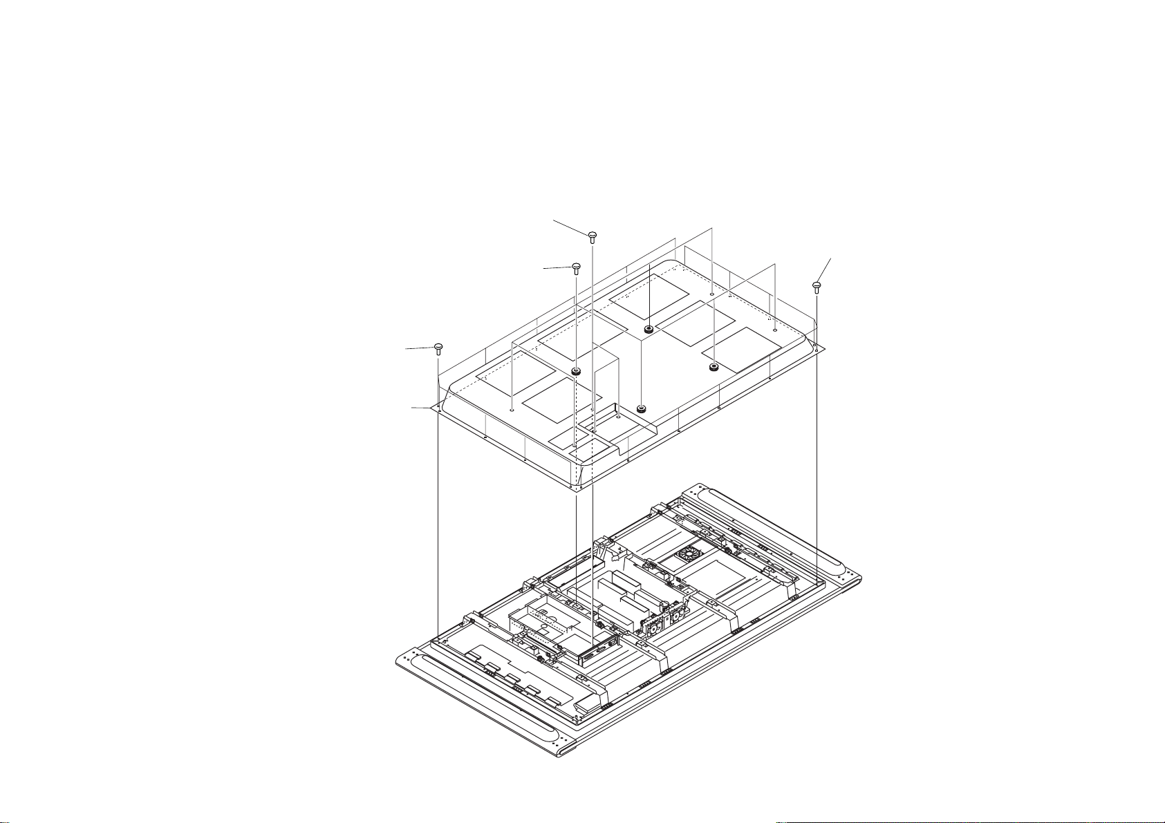
1-1. PANEL UNIT (PDM-4200/5000)
想了解更多的资料请登陆图纸手册交流网站
(http://schematic.5d6d.com)
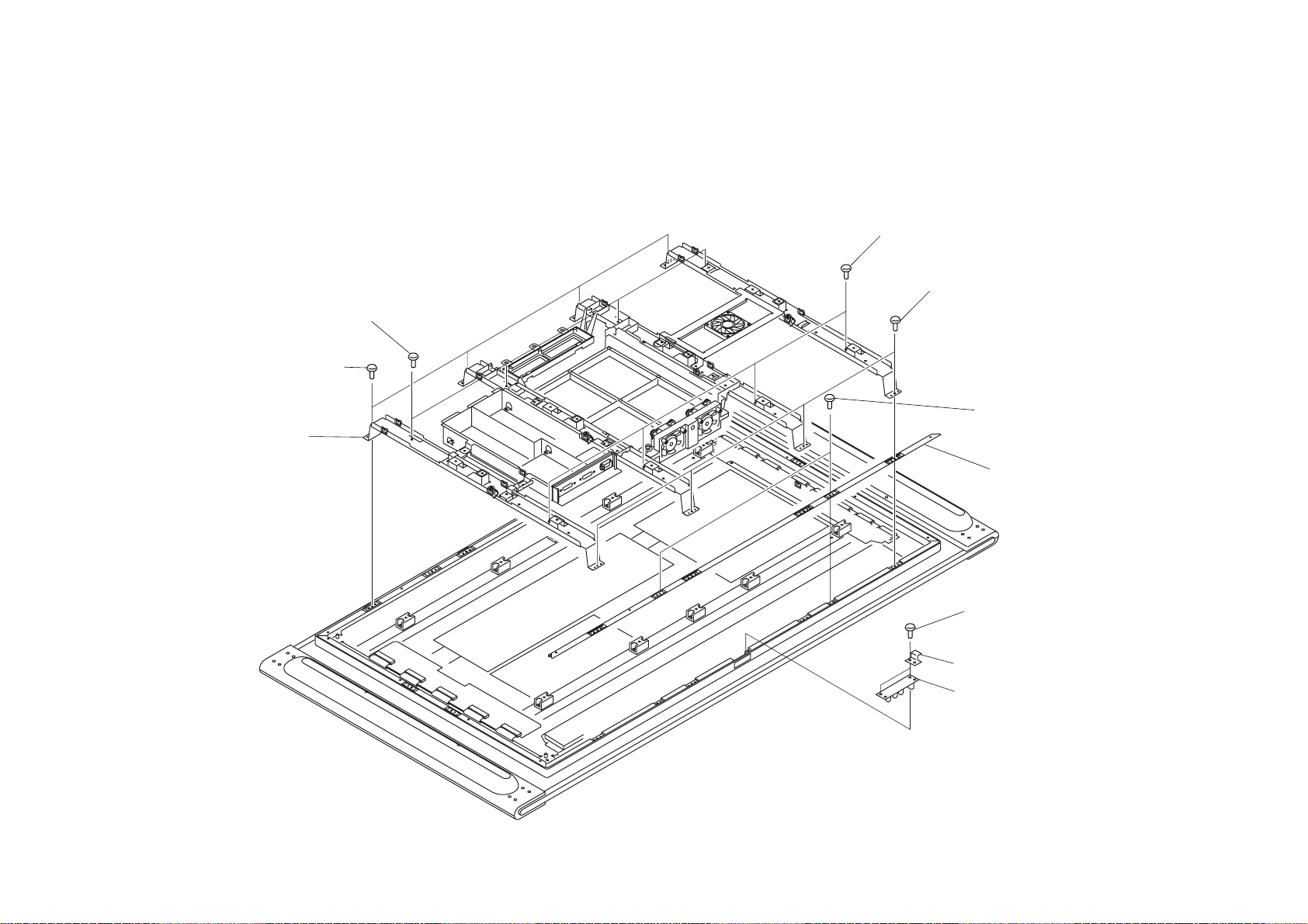
1-1-1. REAR COVER REMOVAL
SECTION 1
DISASSEMBLY
2 Three screws
(+PSW 3X8)
3 Ten screws
(+BVTP 4X16)
4 Rear cover assy
1 Eight screws
(+PSW 5X16)
3 Ten screws
(+BVTP 4X16)
KE-MR42/50M1(CH) 1-1
1-1-2. K AND F BOARDS REMOVAL
想了解更多的资料请登陆图纸手册交流网站
(http://schematic.5d6d.com)
1 Two screws
(+PSW 3X8)
3 Four screws
(+PSW 3X8)
4 K Board
2 F Board
KE-MR42/50M1(CH) 1-2
1-1-3. P BOARD REMOVAL
想了解更多的资料请登陆图纸手册交流网站
(http://schematic.5d6d.com)
3 Four screws
(+PSW 3X8)
4 P Board
1 Two connector screws
2 Two screws
(M2.6 S HEAD)
KE-MR42/50M1(CH) 1-3
1-1-4. G AND F2 BOARDS REMOVAL
3 Three screws
(+BVTP 3X12)
4 F2 Board
1 Seven screws
(+BVTP 3X12)
2 G Board
想了解更多的资料请登陆图纸手册交流网站
(http://schematic.5d6d.com)
KE-MR42/50M1(CH) 1-4
1-1-5. R1 BOARD REMOVAL
想了解更多的资料请登陆图纸手册交流网站
(http://schematic.5d6d.com)
2 Filter bracket (V) assy
1 Two screws
(+BVTP 4X16)
3 Three screws
(+BVTP 3X10)
4 R1 Board
Earth plate
KE-MR42/50M1(CH) 1-5
1-1-6. R2 BOARD REMOVAL
想了解更多的资料请登陆图纸手册交流网站
(http://schematic.5d6d.com)
2 Four screws
(+PSW 5X16)
1 Four screws
(+BVTP 4X16)
3 PANEL assy
2 Four screws
(+PSW 5X16)
1 Four screws
(+BVTP 4X16)
4 Two screws
(+BVTP 4X16)
5 Filter bracket (H) assy
6 Two screws
(+BVTP 3X10)
Earth plate
7 R2 Board
KE-MR42/50M1(CH) 1-6

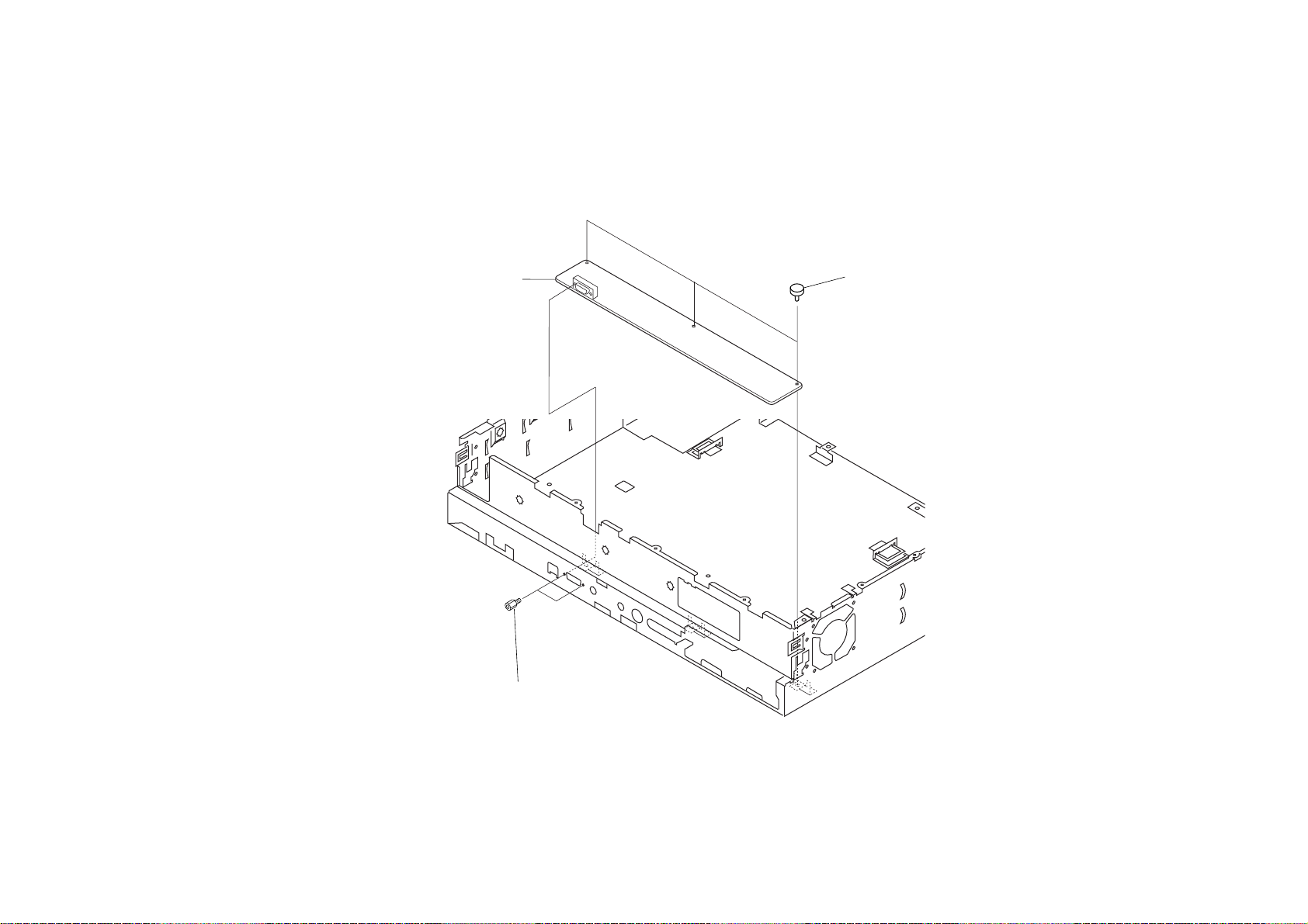
1-2. MEDIA RECEIVER UNIT (MBT-MR1C)
1 Two screws
(M3, SW)
6Two screws
(M3, SW)
0 Rear panel
7 Bottom cover assy
!¡ Front panel assy
1 Two screws
(M3, SW)
3 Eight screws
(Precision)
5 Screw
(+PSW 4X8)
3 Nine screws
(Precision)
2 Top cover
4 Top plate
9 Two screws
(M3, SW)
8 Two Connector screws
想了解更多的资料请登陆图纸手册交流网站
(http://schematic.5d6d.com)
1-2-1. PANEL AND COVERS REMOVAL
KE-MR42/50M1(CH) 1-7
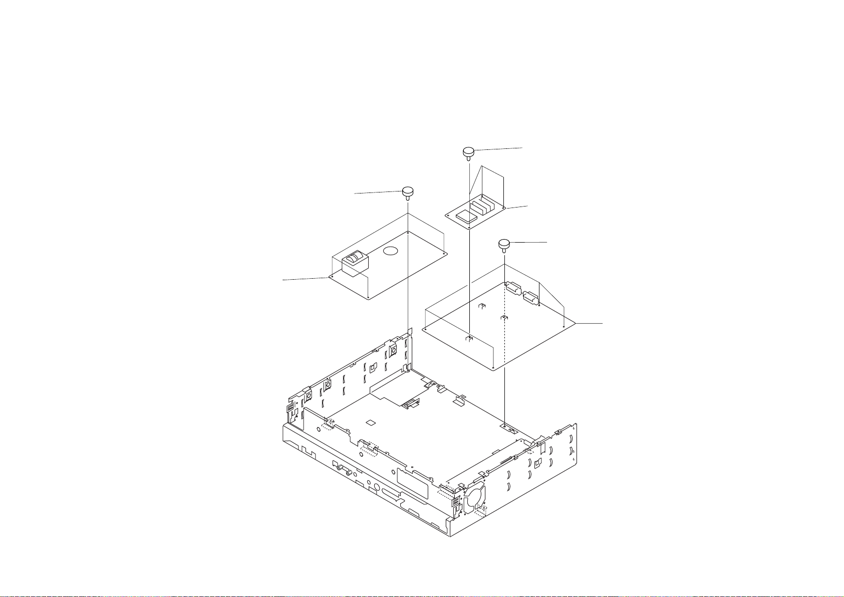
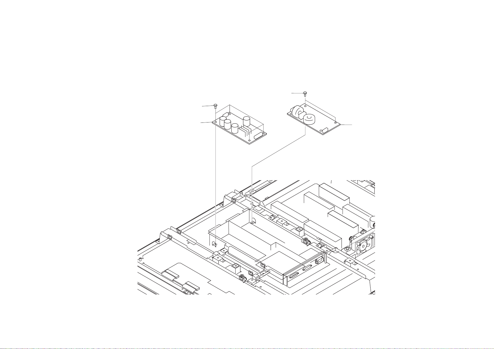
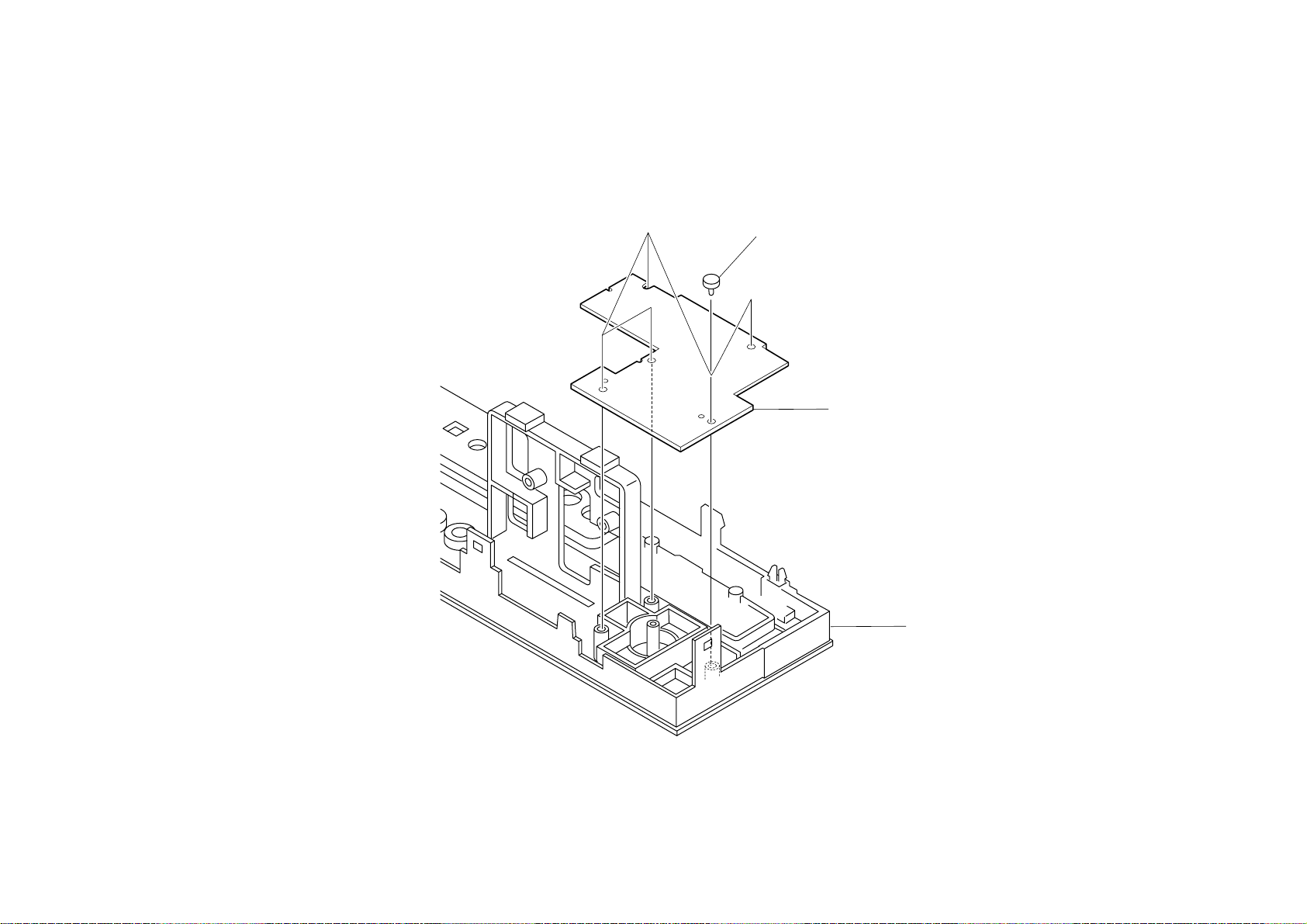
1-2-2. G2, A, AND MS BOARDS REMOVAL
想了解更多的资料请登陆图纸手册交流网站
(http://schematic.5d6d.com)
5 Four screws
(M 3X8)
6 G2 Board
1 Three screws
(+BVTT 3X8)
2 MS Board
3 Five screws
(M 3X8)
4 A Board
KE-MR42/50M1(CH) 1-8
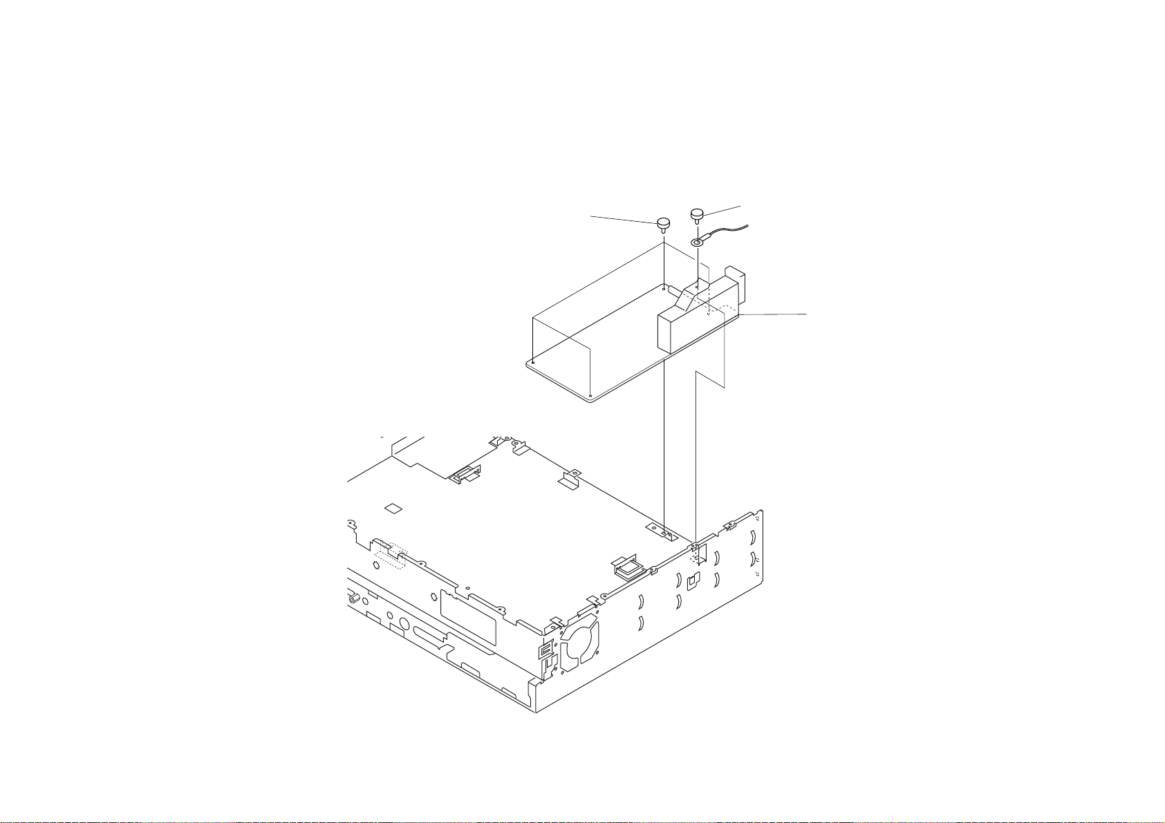
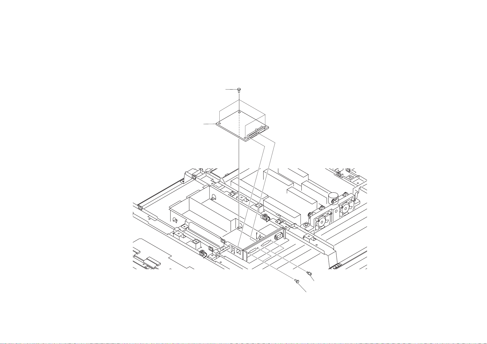
1-2-3. TU BOARD REMOVAL
想了解更多的资料请登陆图纸手册交流网站
(http://schematic.5d6d.com)
2 Four screws
(M 3X8)
1 Screw
(M 3X8)
3 TU Board
KE-MR42/50M1(CH) 1-9
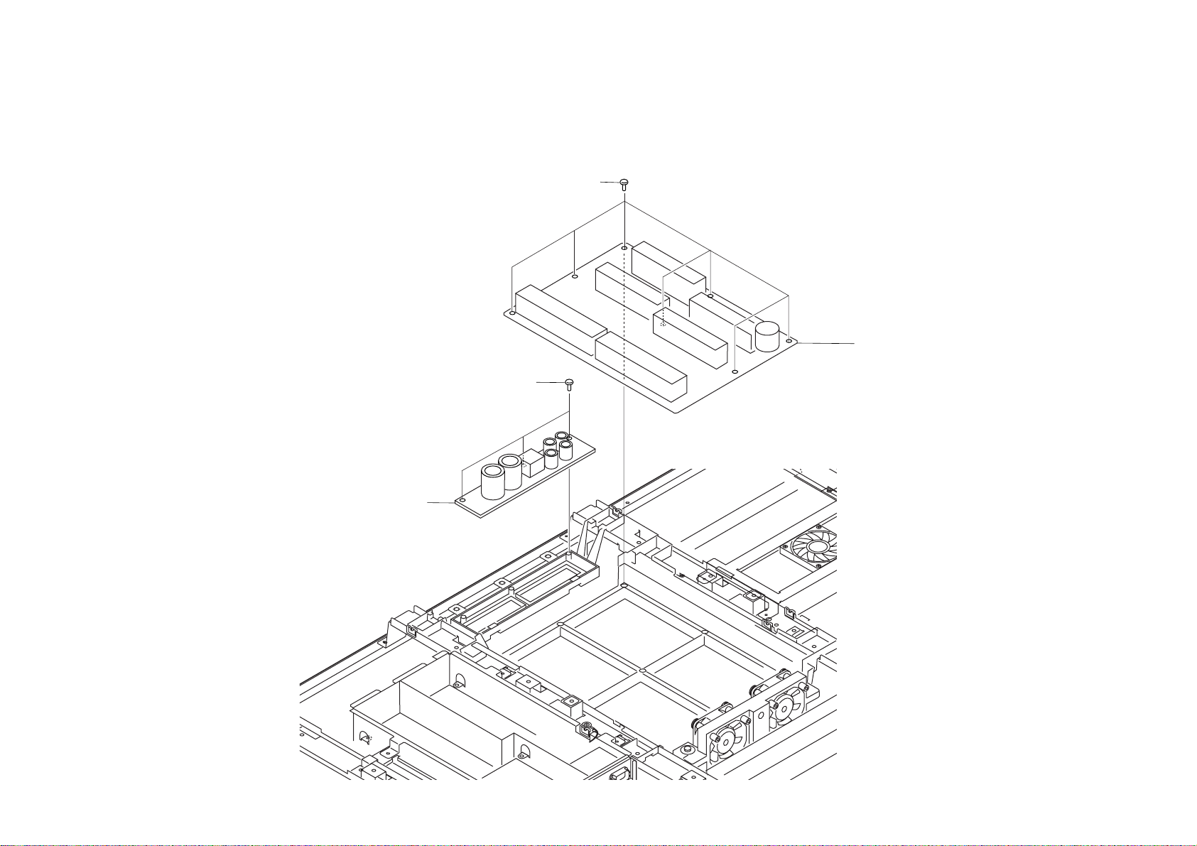
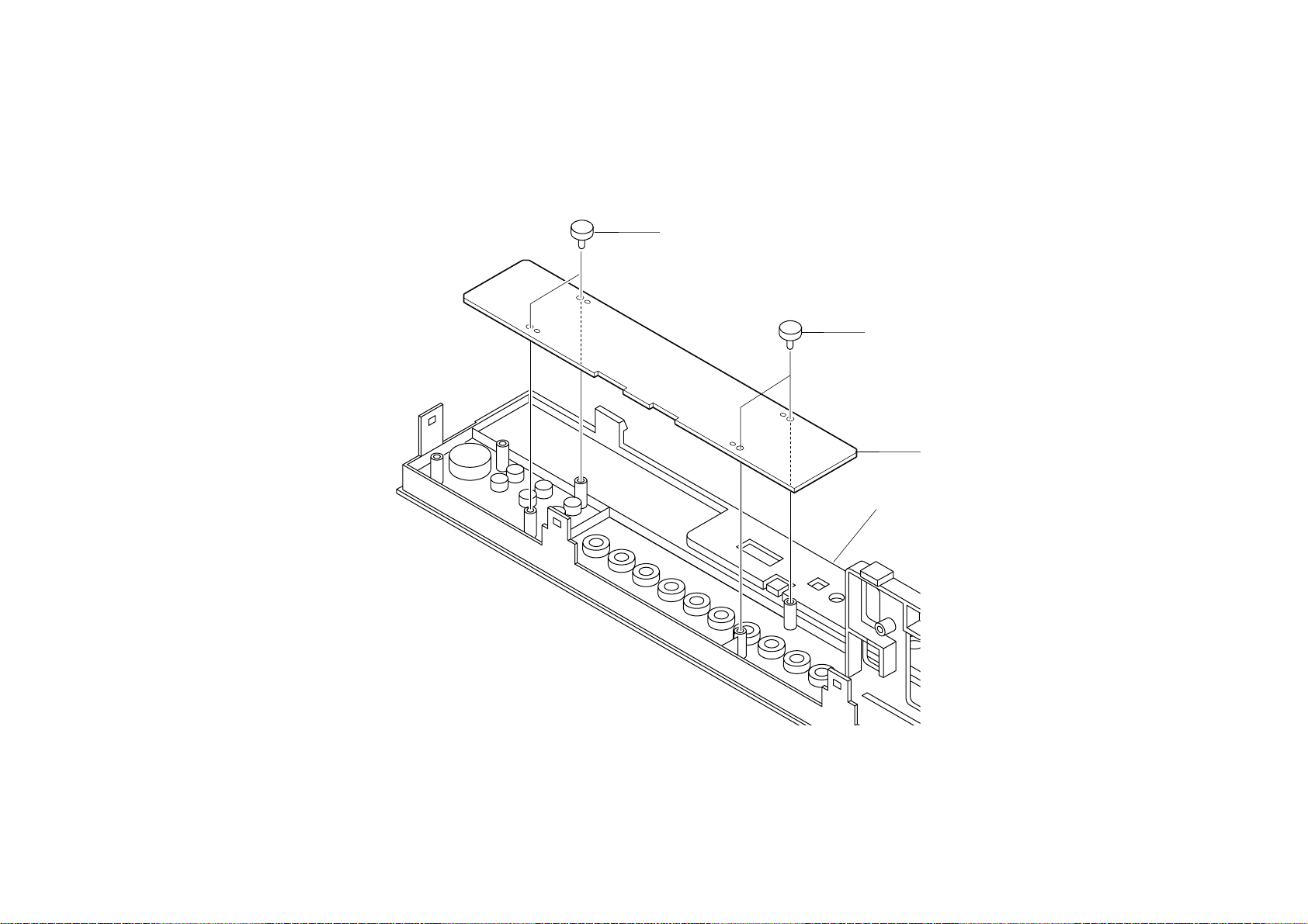
1-2-4. U BOARD REMOVAL
想了解更多的资料请登陆图纸手册交流网站
(http://schematic.5d6d.com)
1 Screw
(+P 3X12)
2 Five screws
(+BVTP 3X12)
3 Two connector screws
2 Four screws
(+BVTP 3X12)
1 Screw
(+P 3X12)
Rear panel
4 U Board
KE-MR42/50M1(CH) 1-10
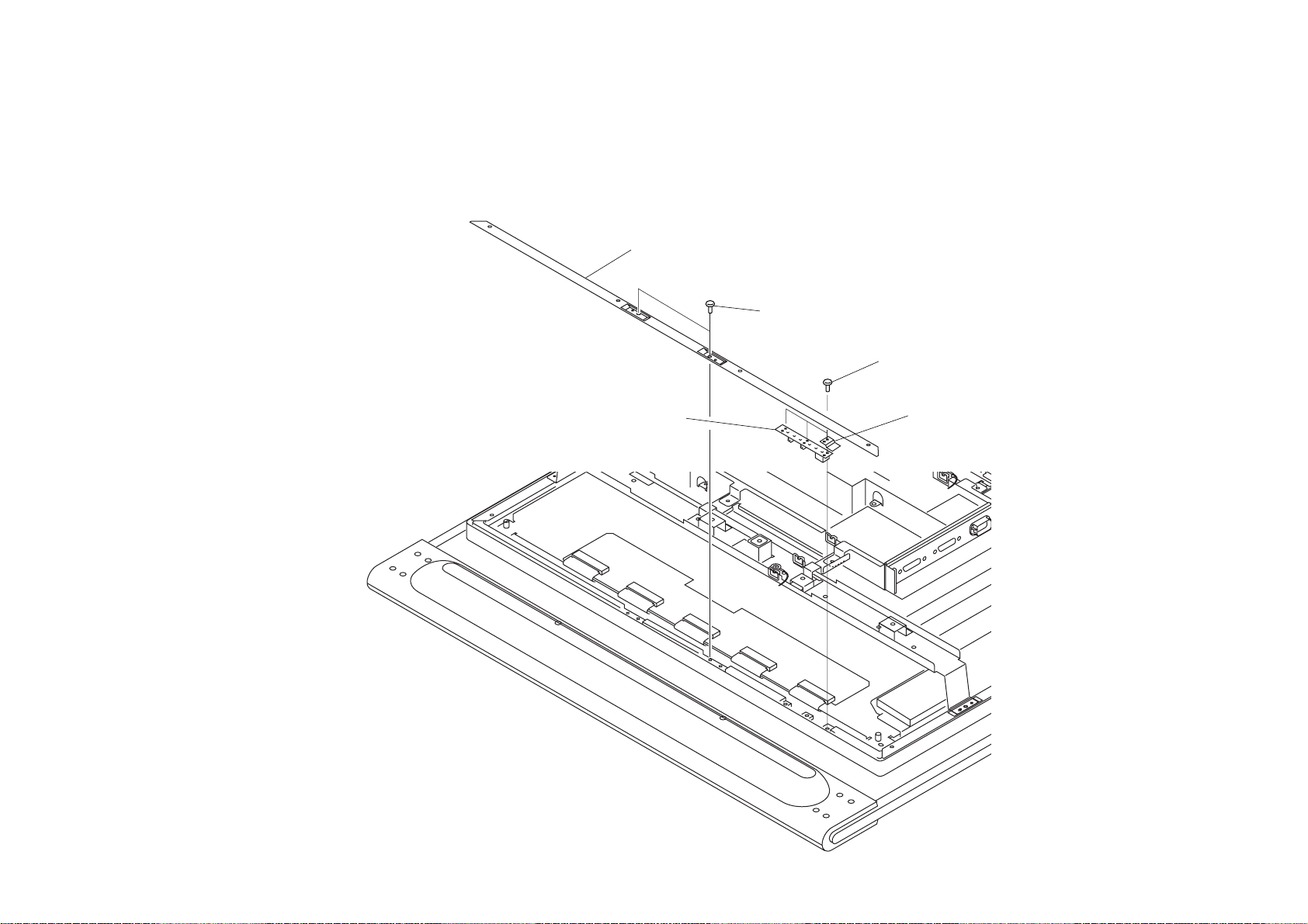
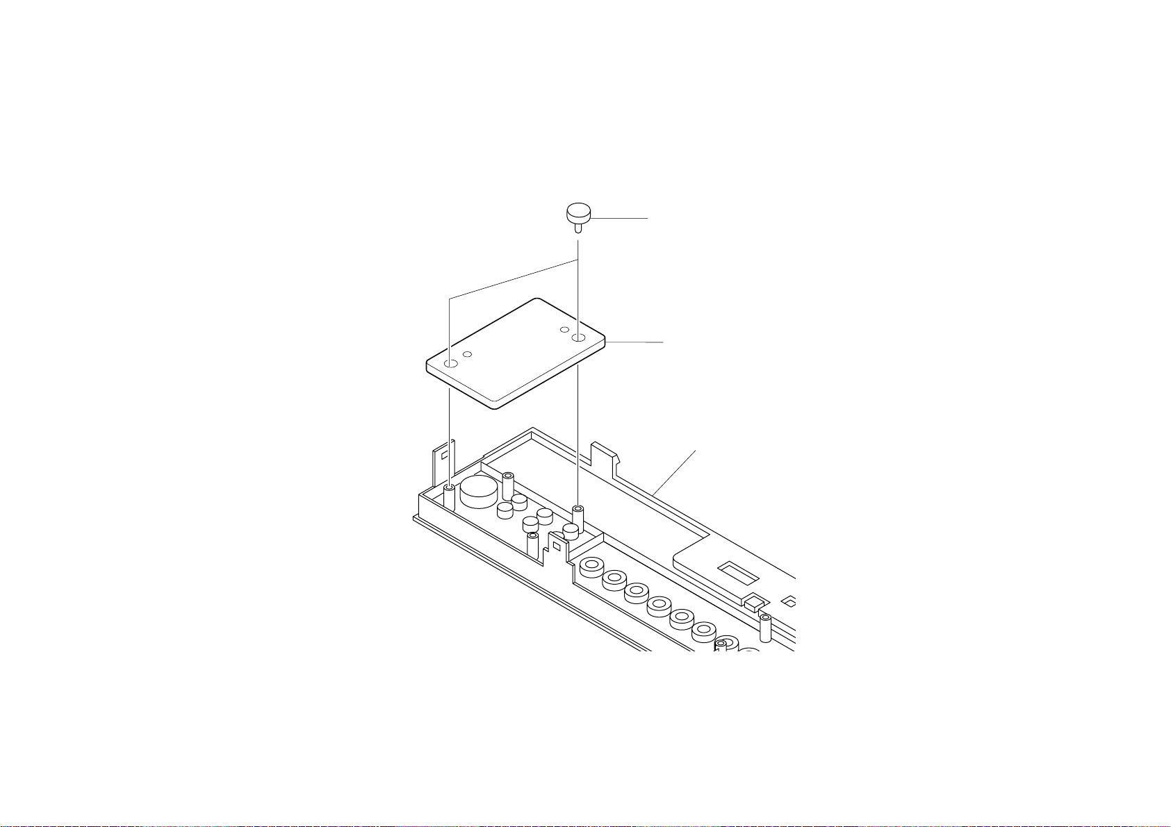
1-2-5. H2 BOARD REMOVAL
想了解更多的资料请登陆图纸手册交流网站
(http://schematic.5d6d.com)
3 H2 Board
1 Three screws
(M 3X8)
2 Two connector screws
KE-MR42/50M1(CH) 1-11
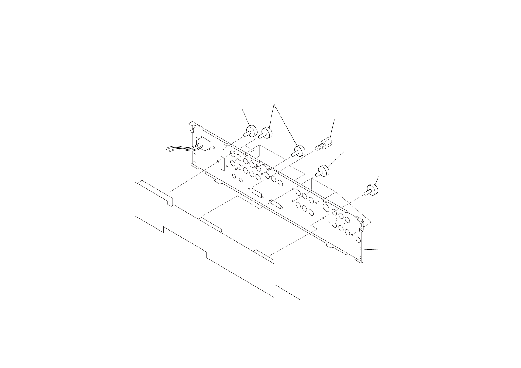
1-2-6. H5 BOARD REMOVAL
想了解更多的资料请登陆图纸手册交流网站
(http://schematic.5d6d.com)
1 Five screws
(+BVTP 3X10)
2 H5 Board
Front panel
KE-MR42/50M1(CH) 1-12

1-2-7. MSX BOARD REMOVAL
想了解更多的资料请登陆图纸手册交流网站
(http://schematic.5d6d.com)
4 MSX Board
3 Two screws
(+BVTP 3X10)
1 Two screws
(+BVTP 3X12)
2 MS bracket
Front panel
KE-MR42/50M1(CH) 1-13
1-2-8. H1 BOARD REMOVAL
想了解更多的资料请登陆图纸手册交流网站
(http://schematic.5d6d.com)
1 Two screws
(+BVTP 3X10)
1 Two screws
(+BVTP 3X10)
2 H1 Board
Front panel
KE-MR42/50M1(CH) 1-14
1-2-9. H4 BOARD REMOVAL
想了解更多的资料请登陆图纸手册交流网站
(http://schematic.5d6d.com)
1 Two screws
(+BVTP 3X10)
2 H4 Board
Front panel
KE-MR42/50M1(CH) 1-15

SECTION 2
想了解更多的资料请登陆图纸手册交流网站
(http://schematic.5d6d.com)
ADJUSTMENTS
2-1. Readjustment of A/D Converter and Video
Decoder Calibration (MBT-MR1C)
<Service Mode>
The service mode is not displayed in the normal state. It is displayed by entering a pass code.
All hidden menus are displayed when you enter the pass code below.
The uppermost item of the displayed menus is a service mode menu.
Pass code: Enter in the standby state (when the red LED lights) as follows:
Screen display → 5 → Vol + → Power ON
== Service Mode Menu ==
1) EEP ROM Initialize
2) Chroma Decoder
3) AD Converter
4) White Balance
5) General
6) Manual Control
7) Preset Edit
8) Service Status
2-1-1. Adjustment Preparation
1) Connect J board via AV mouse.
2) Set Factory Service mode useing AdjCon.xls.
3) Set Thunder to Through mode. (P board)
2-1-2. AD Adjustment of RGB System
1) Input VGA (1024 × 768) All White 90IRE in D-sub 15 pin input.
2) Set picture quality mode to [PC/GAME].
Send “RGB Level” Command.
3) Adjust RGB Gain and set the detection value of RGB to setting values.
Detection setting value: 212 ±3
2-1-3. AD Adjustment of Component (other 15k) System
1) Input 1080/60i All White 90IRE in AV4 or 5 input.
2) Set picture quality mode to [PC/GAME].
Send “RGB Level” Command.
3) Adjust G Gain and set the detection value of Y to setting values.
Detection setting value Y: 212 ±3
4) Set Component Signal to 1080/60i All Gray 20IRE.
5) Adjust G Offset and set the detection value of Y to setting values.
Detection setting value Y: 47 ±1
6) Repeat step 1-5 until it is in a detection setting value.
7) Set Component Signal to 1080/60i All Blue 90IRE.
8) Adjust G Gain and set the detection value of Cb to setting values.
Detection setting value Cb: 234 ±3
9) Set Component Signal to 1080/60i All Black 0IRE.
10) Adjust B Offset and set the detection value of Cb to setting values.
Detection setting value Cb: 128 ±1
11) Repeat step 7-10 until it is in a detection setting value.
12) Set Component Signal to 1080/60i All Red 90IRE.
13) Adjust R Gain and set the detection value of Cr to setting values.
Detection setting value Cr: 234 ±3
14) Set Component Signal to 1080/60i All Black 0IRE.
15) Adjust R Offset and set the detection value of Cr to setting values.
Detection setting value Cr: 128 ±1
16) Repeat step 12-15 until it is in a detection setting value.
4) Set RGB signal to VGA (1024 × 768) All Gray 20IRE.
5) Adjust RGB Offset and set the detection value of RGB to setting values.
Detection setting value: 47 ±1
6) Repeat step 1-5 until it is in a detection setting value.
* Perform this only when the value has shifted in previous “Check of A/D converter and video
decoder calibration” check.
KE-MR42/50M1(CH) 2-1
2-1-4. AD Adjustment of CVBS Video (NTSC) System
(A)
(B) (C) (D)
figure (2)
ML board CN304 3 pin
Blue output
(A)
(B) (C) (D)
figure (3)
ML board CN304 3 pin
Blue output
(A)
(B) (C) (D)
figure (4)
ML board CN304 3 pin
Blue output
想了解更多的资料请登陆图纸手册交流网站
(http://schematic.5d6d.com)
1) Set input to AV1.
2) Input NTSC 50% window Signal 90IRE in AV1.
3) Set picture quality mode to [PC/GAME].
Send “RGB Level” Command.
4) Adjust Y_OUT_LEVEL until the Green detection value is within a setting value.
Detection setting value: 197 ±3
5) Set Video Signal to NTSC 50% window 20IRE.
6) Adjust Cb_OFFSET1 until the detection value of Blue becomes same as that of Green.
7) Adjust Cr_OFFSET1 until the detection value of Red becomes same as that of Green.
8) Repeat step 6-7 until it is in a detection setting value of 8).
Detection setting value: 44
R,G,B detection value dispersion: ±1
9) Repeat step 2-7 until it is in the detection setting value of 4) and 8).
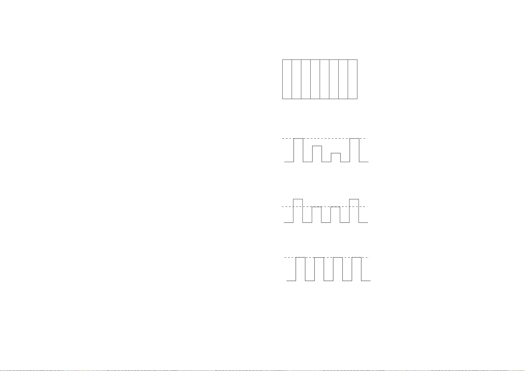
10) Input NTSC 75% Color Bar signal into AV1. (Fig. 1)
11) Adjust C_OUT_LEVEL until the detection value of (A) becomes same as that of (D), as
shown in the right figure 2.
12) Adjust Hue until the detection value of (B) becomes same as that of (C), as shown in the right
figure 3.
13) Repeat step 11-12 until the detection value of (A), (B), (C) and (D) becomes the same, as
shown in the right figure 4.
+2
–6
75% Color Bar
(A) (B) (C) (D)
xxxx
Wh Ye Cy G Mg R Bl Bk
Cautions :
figure (1)
The position of (A) excepts between
for 1/16 from an edge.
KE-MR42/50M1(CH) 2-2

2-1-5. AD Adjustment of CVBS Video (PAL) System
(A)
(B) (C) (D)
figure (2)
ML board CN304 3 pin
Blue output
想了解更多的资料请登陆图纸手册交流网站
(http://schematic.5d6d.com)
1) Set input to AV1.
2) Input PAL 50% window Signal 90IRE in AV1.
3) Set picture quality mode to [PC/GAME].
Send “RGB Level” Command.
4) Adjust Y_OUT_LEVEL until the Green detection value is within a setting value.
2-1-6. AD Adjustment of CVBS Video (PAL60) System
1) Set input to AV1.
2) Input PAL60 50% window Signal 90IRE in AV1.
3) Set picture quality mode to [PC/GAME].
Send “RGB Level” Command.
4) Adjust Y_OUT_LEVEL until the Green detection value is within a setting value.
Detection setting value: 197 ±3
5) Set Video Signal to PAL 50% window 20IRE.
6) Adjust Cb_OFFSET1 until the detection value of Blue becomes same as that of Green.
7) Adjust Cr_OFFSET1 until the detection value of Red becomes same as that of Green.
8) Repeat step 6-7 until it is in a detection setting value of 8).
Detection setting value: 44
+2
–6
R,G,B detection value dispersion: ±1
9) Repeat step 2-7 until it is in the detection setting value of 4) and 8).
10) Input PAL 75% Color Bar signal into AV1.
11) Adjust C_OUT_LEVEL until the detection value of (A) becomes same as that of (D), as
shown in the figure 2.
75% Color Bar
(A) (B) (C) (D)
xxxx
Wh Ye Cy G Mg R Bl Bk
Cautions :
figure (1)
The position of (A) excepts between
for 1/16 from an edge.
ML board CN304 3 pin
Blue output
Detection setting value: 197 ±3
5) Set Video Signal to PAL60 50% window 20IRE.
6) Adjust Cb_OFFSET1 until the detection value of Blue becomes same as that of Green.
7) Adjust Cr_OFFSET1 until the detection value of Red becomes same as that of Green.
8) Repeat step 6-7 until it is in a detection setting value of 8).
Detection setting value: 44
+2
–6
R,G,B detection value dispersion: ±1
9) Repeat step 2-7 until it is in the detection setting value of 4) and 8).
10) Input PAL60 75% Color Bar signal into AV1.
11) Adjust C_OUT_LEVEL until the detection value of (A) becomes same as that of (D), as
shown in the right figure 2.
(Note)
Adjustment is omissible.
The adjustment value of PAL60 copies that of NTSC.
75% Color Bar
(A) (B) (C) (D)
xxxx
Wh Ye Cy G Mg R Bl Bk
Cautions :
figure (1)
The position of (A) excepts between
for 1/16 from an edge.
(A)
(B) (C) (D)
figure (2)
KE-MR42/50M1(CH) 2-3

2-1-7. AD Adjustment of YC Video (NTSC) System
(A)
(B) (C) (D)
figure (2)
ML board CN304 3 pin
Blue output
(A)
(B) (C) (D)
figure (3)
ML board CN304 3 pin
Blue output
(A)
(B) (C) (D)
figure (4)
ML board CN304 3 pin
Blue output
想了解更多的资料请登陆图纸手册交流网站
(http://schematic.5d6d.com)
1) Set input to AV1.
2) Input NTSC All 50% window signal 90IRE in AV1.
3) Set picture quality mode to [PC/GAME].
Send “RGB Level” Command.
4) Adjust Y_OUT_LEVEL until the Green detection value is within a setting value.
Detection setting value: 197 ±3
5) Set Video Signal to NTSC 50% window 20IRE.
6) Adjust Cb_OFFSET1 until the detection value of Blue becomes same as that of Green.
7) Adjust Cr_OFFSET1 until the detection value of Red becomes same as that of Green.
8) Repeat step 6-7 until it is in a detection setting value of 8).
Detection setting value: 44
R,G,B detection value dispersion: ±1
9) Repeat step 2-7 until it is in the detection setting value of 4) and 8).
10) Input NTSC 75% Color Bar signal into AV1. (Fig. 1)
11) Adjust C_OUT_LEVEL until the detection value of (A) becomes same as that of (D), as
shown in the right figure 2.
12) Adjust Hue until the detection value of (B) becomes same as that of (C), as shown in the right
figure 3.
13) Repeat step 11-12 until the detection value of (A), (B), (C) and (D) becomes the same, as
shown in the right figure 4.
+2
–6
75% Color Bar
(A) (B) (C) (D)
xxxx
Wh Ye Cy G Mg R Bl Bk
Cautions :
figure (1)
The position of (A) excepts between
for 1/16 from an edge.
KE-MR42/50M1(CH) 2-4

2-1-8. AD Adjustment of YC Video (PAL) System
(A)
(B) (C) (D)
figure (2)
ML board CN304 3 pin
Blue output
想了解更多的资料请登陆图纸手册交流网站
(http://schematic.5d6d.com)
1) Set input to AV3.
2) Input PAL 50% window Signal 90IRE in AV1.
3) Set picture quality mode to [PC/GAME].
Send “RGB Level” Command.
4) Adjust Y_OUT_LEVEL until the Green detection value is within a setting value.
2-1-9. AD Adjustment of YC Video (PAL60) System
1) Set input to AV1.
2) Input PAL60 50% window Signal 90IRE in AV1.
3) Set picture quality mode to [PC/GAME].
Send “RGB Level” Command.
4) Adjust Y_OUT_LEVEL until the Green detection value is within a setting value.
Detection setting value: 197 ±3
5) Set Video Signal to PAL 50% window 20IRE.
6) Adjust Cb_OFFSET1 until the detection value of Blue becomes same as that of Green.
7) Adjust Cr_OFFSET1 until the detection value of Red becomes same as that of Green.
8) Repeat step 6-7 until it is in a detection setting value of 8).
Detection setting value: 44
+2
–6
R,G,B detection value dispersion: ±1
9) Repeat step 2-7 until it is in the detection setting value of 4) and 8).
10) Input PAL 75% Color Bar signal into AV1.
11) Adjust C_OUT_LEVEL until the detection value of (A) becomes same as that of (D), as
shown in the figure 2.
75% Color Bar
(A) (B) (C) (D)
xxxx
Wh Ye Cy G Mg R Bl Bk
Cautions :
figure (1)
The position of (A) excepts between
for 1/16 from an edge.
ML board CN304 3 pin
Blue output
Detection setting value: 197 ±3
5) Set Video Signal to PAL60 50% window 20IRE.
6) Adjust Cb_OFFSET1 until the detection value of Blue becomes same as that of Green.
7) Adjust Cr_OFFSET1 until the detection value of Red becomes same as that of Green.
8) Repeat step 6-7 until it is in a detection setting value of 8).
Detection setting value: 44
+2
–6
R,G,B detection value dispersion: ±1
9) Repeat step 2-7 until it is in the detection setting value of 4) and 8).
10) Input PAL60 75% Color Bar signal into AV1.
11) Adjust C_OUT_LEVEL until the detection value of (A) becomes same as that of (D), as
shown in the right figure 2.
(Note)
Adjustment is omissible.
The adjustment value of PAL60 copies that of NTSC.
75% Color Bar
(A) (B) (C) (D)
xxxx
Wh Ye Cy G Mg R Bl Bk
Cautions :
figure (1)
The position of (A) excepts between
for 1/16 from an edge.
(A)
(B) (C) (D)
figure (2)
KE-MR42/50M1(CH) 2-5

2-1-10. AD Adjustment of Component (15k) System
想了解更多的资料请登陆图纸手册交流网站
(http://schematic.5d6d.com)
1) Set input to AV4 (or 5).
2) Input component PAL 50% window Signal 90IRE in AV4 (or 5).
3) Set picture quality mode to [PC/GAME].
Send “RGB Level” Command.
4) Adjust Y_OUT_LEVEL until the Green detection value is within a setting value.
Detection setting value: 197 ±3
5) Set Video Signal to component PAL 50% window 20IRE.
6) Adjust Cb_OFFSET2 until the detection value of Blue becomes same as that of Green.
7) Adjust Cr_OFFSET2 until the detection value of Red becomes same as that of Green.
8) Repeat step 6-7 until it is in a detection setting value of 8).
Detection setting value: 44
R,G,B detection value dispersion: ±1
9) Repeat step 2-7 until it is in the detection setting value of 4) and 8).
10) Input component PAL 75% Color Bar signal into “AV4 (or 5)”.
11) Adjust C_OUT_LEVEL until the detection value of (A) becomes same as that of (D), as
shown in the figure 2.
75% Color Bar
(A) (B) (C) (D)
+2
–6
xxxx
Wh Ye Cy G Mg R Bl Bk
Cautions :
figure (1)
(A)
figure (2)
The position of (A) excepts between
for 1/16 from an edge.
(B) (C) (D)
ML board CN304 3 pin
Blue output
KE-MR42/50M1(CH) 2-6

2-2. VS, VD Voltage Adjustment (PDM-4200/5000)
想了解更多的资料请登陆图纸手册交流网站
(http://schematic.5d6d.com)
• Preparation for adjustment
1.Slide the DIP switch (S3201) No. 8 of P board to on position with no silkscreen mark r.
2.Connect a digital voltmeter to the following terminals of G board.
VS voltage=G board TP1701 (VS)-TP1502 (GND)
VD voltage=G board TP1501 (VD)-TP1502 (GND)
3.Connect a AC cord in DISPLAY UNIT.
4.Perform the adjustment in 10 seconds after connecting the cord.
• Procedure for adjustment
1. Slide the DIP switch (S3201) No. 7 of P board to on position with no silkscreen mark r.
2. Confirm the lighting of SONY LOGO LED.
3. Adjust the VS voltage to the following voltage value.
VS voltage of proper value for each model.
Ex.) VS proper value=185V thru 185.6V at 185V.
(Check the proper value with a seal on upper left of panel unit. Refer to right Fig.)
4. Adjust the VD voltage to the following voltage value.
VD voltage ±0.3V of proper value for each model.
Ex.) VD proper value=64.7V thru 65.3V at 65.0V.
(Check the proper value with a seal on upper left of panel unit. Refer to right Fig.)
5. Check a Fan rotation.
6. Slide the DIP Switch (S3201) No. 7 of P board to the off position with the silkscreen mark
r.
7. Slide the DIP Switch (S3201) No. 8 of P board to the off position with the silkscreen mark
r.
8. Disconnect an AC cord of DISPLAY UNIT.
9. Reconnect the AC cord in one second.
10. Assure that “POWER ON/STANDBY” LEDs is flashing amber.
+6V
–0V
<SEAL POSITION>
BAR CODE SEAL
SERIAL No.
301201440
Vd=65V
Vs=193.4V
CODE AA-01
Panel unit
Rear cover assy
KE-MR42/50M1(CH) 2-7
2-3. White Balance Adjustment (PDM-4200/5000)
想了解更多的资料请登陆图纸手册交流网站
(http://schematic.5d6d.com)
• Measurement equipment
1.Color analyzer (CA-100 manufactured by MINOLTA)
1.Signal generator (ASTRO DESIGN VG-828D)
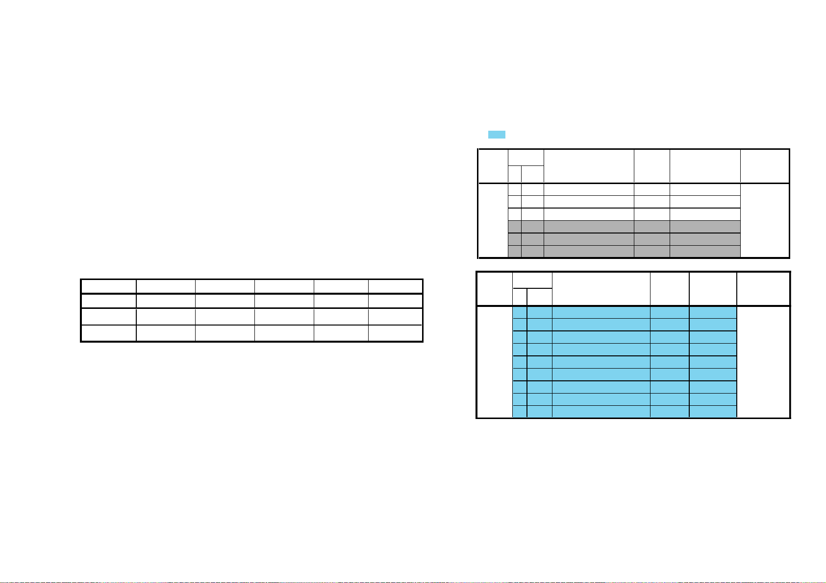
• Service mode lists
Caution: 1. Setting functions of Display section are displayed with yellow OSD.
2. Be careful not to set DATA in the yellow-covered OSD menu. The setting will be
memorized.
3. items are not required adjustment or are banned adjustment
• Measuring procedure
1. Dab the W/B adjustment jig (CA-100) at the glass face of the panel.
2. Connect the Signal generator (VG-828D) to the DVI terminal.
3. Input All-white signal and set the picture mode to DYNAMIC.
4. Select”PNLCTRL” in the service mode menu and set “0 WBNO” at “0”
5. Select “SCNR” “SCNB” of “PDPWB” in the service mode menu, and then adjust following
W/B standardized values of 6500K, 8000K, 9300K, 10000K and 13550K to following values
of X/Y.
W/B standardized values:
6500K+8MPCD 8000K+8MPCD 9300K+8MPCD 10000K 13550K
W/B 01234
X 0.3133±0.003 0.2944±0.003 0.2838±0.003 0.2806±0.003 0.2684±0.003
Y 0.3297±0.003 0.3100±0.003 0.2981±0.003 0.2883±0.003 0.2700±0.003
6. After adjusting the values, at the values of the “SCNR” or “SCNB” exceeding 128 (initialize
value).
1)Reset a lager value of the “SCNR” or “SCNB” at 128.
2)Set the White Balances with the last of items and “SCNG” to the X/Y values above.
7. After the above step, when these item are nonqualified following conditions, set the largest
one at 128 and readjust the White Balance with the last two item.
1)No one of “SCNR”, “SCNB” and “SCNG” exceeding 128
2)Confirm the item value 128 at least one item
8. As a result above, input the sequential number of value to the “SCNR”, “SCNB” and
“SCNG”.
9. Repeat the same step 5 thru 8 for the W/B 1 thru 4 after setting the “0 WBNO” at each W/B
number.
10.Input following signals from the Signal generator (VG-828D).
1)All-white signal (255/255) input Y (luminance)=45cd/m
2)1/25Window (255/255) input Y (luminance)=45cd/m
2
or more
2
or more
Category
PDPWB 00 SCNR Sub contrast RED gain
Category
PDPSHAP 00 CRMD
Item Function Data range Initialize value Device Name
No. Name (Slave Address)
01 SCNG Sub contrast GREEN gain
02 SCNB Sub contrast BLUE gain
03 SBRR Sub brightness RED
04 SBRG Sub brightness GREEN
05 SBRB
No. Name (Slave Address)
Sub brightness BLUE
Item Function Data range Initialize value Device Name
01 HTAP
02 VTAP
03 AGCM
04 EDDL
05 EDGA
06 EDNM
07 EDDE
08 DHVS
0-255 128 CXD9738R
0-255 128
0-255 128
0-255 128(Fix)
0-255 50"=127/42"=128(Fix)
0-255 128(Fix)
KE-MR42/50M1(CH) 2-8
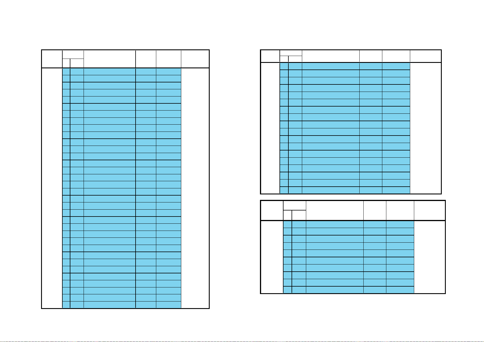
Category
想了解更多的资料请登陆图纸手册交流网站
(http://schematic.5d6d.com)
PDPGMMA 00 GMMA
Item Function Data range Initialize value Device Name
No. Name (Slave Address)
01 GMR0
02 GMR1
03 GMR2
04 GMR3
05 GMR4
06 GMR5
07 GMR6
08 GMR7
09 GMR8
10 GMR9
11 GMRA
12 GMG0
13 GMG1
14 GMG2
15 GMG3
16 GMG4
17 GMG5
18 GMG6
19 GMG7
20 GMG8
21 GMG9
22 GMGA
23 GMB0
24 GMB1
25 GMB2
26 GMB3
27 GMB4
28 GMB5
29 GMB6
30 GMB7
31 GMB8
32 GMB9
33 GMBA
Category
Item Function Data range Initialize value Device Name
No. Name (Slave Address)
PDPPLE 00 PLE0
01 PLE1
02 PLE2
03 PLE3
04 PLE4
05 PLE5
06 PLE6
07 PLE7
08 PLE8
09 PLE9
10 PLEA
11 LMAX
12 LMIN
13 GAIN
14 OFFS
15 SAFL
16 LIFH
17 SPLE
Category
Item Function Data range Initialize value Device Name
No. Name (Slave Address)
PDPDYPIC 00 TLVL
01 TFVL
02 THLD
03 PLVL
04 PFIL
05 PHLD
06 PGUP
07 PGDN
08 PHIS
09 PGAN
KE-MR42/50M1(CH) 2-9
 Loading...