

Sony KDP-65XBR2, KDP-57XBR2 Owner’s Manual

0 2001 by Sony Corporation KDP-57XBR2 KDP-65XBR2

WARNING
To reduce the risk of fire or shock hazard, do not expose the
projection TV to rain or moisture.
RISK OF ELECTRIC SHOCK
DO NOT OPEN
A'R'ENTION
RISQUE DE CHOC ELECTRIOUE,
NE PAS OUVRIR
PRECAUClON
RIESGO DE CHOQUE ELECTRICO
CAUTION: TO REDUCE THE RISK OF ELECTRICSHOCK,
DO NOT REMOVE COVER (OR BACK).
NO USER-SERVICEABLEPARTSINSIDE.
REFERSERVICING TO QUALIFIED SERVICE PERSONNEL
This symbol is intended to alert the user to the
presence of uninsulated "dangerous voltage"
within the product's enclosure that may be of
sufficient magnitude to constitute a risk of
electric shock to persons.
This symbol is intended to alert the user to the
presence of important operating and maintenance
(servicing) instructions in the literature
accompanying the appliance.
NO ABRIR
CAUTION
To prevent electric shock, do not use this polarized AC plug with
an extension cord, receptacle or other outlet unless the blades can
be fully inserted to prevent blade exposure.
CAUTION
When using TV games, computers, and similar
products with your projection TV, or viewing a
TV station whose logo always stays on the
screen, keep the brightness and contrast
functions at low settings. If a fixed (non-moving)
pattern such as a station logo is left on the screen
for long periods of time, especially at a high
brightness or contrast setting, the image can be
permanently imprinted onto the screen. These
types of imprints are not covered by your
warranty.
Note on Caption Vision
This television receiver provides display of television closed
captioning in accordance with §15.119 of the FCC rules.
Note on Convergence Adjustment
Before you use your projection TV, make sure to adjust
convergence. For details, see "Adjusting the Convergence
Automatically (Flash Focus)" on page 36.
Note to CATV System Installer
This reminder is provided to call the CATV system installer's
attention to Article 820-40 of the NEC that provides guidelines for
proper grounding and, in particular, specifies that the cable ground
shall be connected to the grounding system of the building, as close
to the point of cable entry as practical.
Use of this television receiver for other than private viewing of
programs broadcast on UHF or VHF or transmitted by cable
companies for the use of the general public may require
authorization from the broadcaster/cable company and/or
program owner.
NOTIFICATION
This equipment has been tested and found to comply with the
limits for a Class B digital device pursuant to Part 15 of the FCC
Rules. These limits axe designed to provide reasonable protection
against harmful interference in a residential installation. This
equipment generates, uses, and can radiate radio frequency energy
and, if not installed and used in accordance with the instructions,
may cause harmful interference with radio communications.
However, there is no guarantee that interference will not occur in a
particular installation, if this equipment does cause hanninl
interference to radio or television reception, which can be
determined by turning the equipment off and on, the user is
encouraged to try to conect the interference by one or more of the
following measures:
N Reorient or relocate the receiving antennas.
F1 Increase the separation between the equipment and receiver.
F1 Connect the equipment into an outlet on a circuit different
from that to which the receiver is connected.
[7 Consult the dealer or an experienced radio/TV technician for
help.
You are cautioned that any changes or modifications not expressly
approved in this manual could void your authority, to operate this
equipment.
Safety
[1 Operate the projection TV only on 120 V AC.
[1 The plug is designed, for safety purposes, to fit into the wall
outlet only one way. If you are unable to insert the plug fully
into the outlet, contact your dealer.
VI If any liquid or solid object should fall inside the cabinet,
unplug the projection TV immediately and have it checked
by qualified service personnel before operating it further.
71 If you will not be using the projection TV for several days,
disconnect the power by pulling the plug liselL Never pull on
the cord.
[7 For details concerning safety precautions, see "Important
Safeguards."
Installing
To prevent internal heat buildup, do not block the ventilation
openings.
Do not install the projection TV in a hot or humid place, or in
a place subject to excessive dust or mechanical vibration.
D Avoid operating the projection TV at temperature below 5°C
(41°F).
VI If the projection TV is transported dii_ctly from a cold to a
warm location, or if the room temperature changes suddenly,
the picture may be blurred or show poor color. In this case,
please wait a few hours to let the moisture evaporate before
turning on the projection TV.
FI To obtain the best picture, do not expose the screen to direct
illumination or direct sunlight. It is recommended to use spot
lighting directed down from the ceiling or to cover the
windows that face the screen with opaque drapery. It is
desirable to install the projection TV in a room where the
floor and walls are not of a reflective material.
Trademark Information
DO [DOLBY ] ManufacfuredunderlicensefromDolby
D I (I I T A L Dolbyand the double-D symbolare
XBR is a registered trademark and CineMotion is a trademark of
Sony.
i.LINK is a h'ademark of Sony used only to designate that a
product contains an IEEE 1394 connector. All products with an
i.LINK connector may not communicate with each other.
Laboratories Licensing Corporation.
trademarks of Dolby Laboratories
Licensing Corporation.
Owner's Record
The model and serial numbers are located at the rear of the
projection TV, below the Sony logo, on the sticker, and also on the
TV box (white label). Record these numbers in the spaces provided
below. Refer to them whenever you call upon your Sony dealer
regarding this product.
Model No.
SerialNo.
Sony has determined that this
product or product models meets
I_ As an ENERGYSTAR®Partner,
ENERGYSTAR_ is a U.S. registered mark.
the ENERGYSTAR®guidelines
for energy efficiency.

Important Safeguards
For your protection, please read these instructions completely, and
keep this manual for future reference.
Carefully observe and comply with all warnings, cautions and
instructions placed on the set or described in the operating
instructions or service manual.
WARNING
To guard against injury, the following basic safety precautions
should be observed in the installation, use and servicing of the set.
Use
Power Sources
This set should be operated only from the type
of power source indicated on the serial/model
plate. If you are not sure of the type of electrical
power supplied to your home, consult your
dealer or local power company. For those sets
designed to operate from battery power, refer
to the operating instructions.
Grounding or Polarization
This set is equipped with a polarized AC power cord plug (a plug
having one blade wider than the other), or with a three-wire
grounding type plug (a plug having a third pin for
gmunding).Foliow the insti-uctions below:
For the set with a polarized AC power cord plug
This plug will fit into the power outlet only one
way. This is a safety feature. If you are unable to
insert the plug fully into the outlet, try reversing
the plug. If the plug still fails to fit, contact your electrician to have
a suitable outlet installed. Do not defeat the safety purpose of the
polarized plug by forcing it in.
Object and Liquid Entry
Never push objects of any kind into the set
through the cabinet slots as they may touch
dangerous voltage points or short out parts that
could result in a fire or electric shock. Never spill
liquid of any kind on the set.
Cleaning
Clean the cabinet of the projection TV with a dry
soft cloth. To remove dust from the screen, wipe f_,_ _2)
it gently with a soft cloth. Stubborn stains may
be removed with a cloth silghtly dampened with [_
solution of mild soap and warm water. Never
use strong solvents such as thinner or benzine for cleaning.
If the picture becomes dark after using the projection TV for a long
period of time, it may be necessary to clean the inside of the
projection TV. Consult qualified service personnel.
Installation
Attachments
Do not use attachments not recommended by the
manufacturer, as they may cause hazards.
Water and Moisture
Do not use power-line operated sets near
water -- for example, near a bathtub,
washbowl, kitchen sink, or laundry tub, in a
wet basement, or near a swimming pool etc.
Alternate Warning
For the set with a three-wire grounding type AC plug
This plug will only fit into a grounding-type
power outlet. This is a safety feature. If you are .___/_ "_
unable to insert the plug into the outlet, contact
your electrician to have a suitable outlet installed.
Do not defeat the safety purpose of the grounding plug.
Overloading
DO not overload wall outlets, extension cords or
convenience _ceptacles beyond their capacity,
since this can result in fire or electric shock.
Always turn the set off when it is not being
used. When the set is left unattended and
unused for long periods of time, unplug it
from the wall outlet as a precaution against
the possibility of an internal malfunction that
could create a fire hazard.
If a snapping or popping sound from a TV set is
continuous or frequent while the TV is operating,
unplug the TV and consult your dealer or service
technician. It is normal for some TV sets to make
occasional snapping or popping sounds,
particularly when being turned on or off.
Accessories
Do not place the set on an unstable cart, stand, ,,2, •
table or shelf. The set may fall, causing serious .._1, /_]J."
injury to a child or an adult and serious damage
to the set. Use only a cart or stand recommended ____,_-
by Sony for the specific model of TV. No part of
the TV set should overhang any edge of the TV
cart or stand; any overhanging edge is a safety
hazard. An appliance and cart combination
should be moved with care. Quick stops,
excessive force, and uneven surfaces may cause
the appliance and cart combination to overturn. ,,-.
Ventilation
The slots and openings in the cabinet and in the back or bottom are
provided for necessary ventilation. To ensure reliable operation of
the set, and to protect it from overheating, these slots and openings
must never be blocked or covered.
FI Never cover the slots and openings with a
cloth or other materials.
7-1 Never block the slots and openings by
placing the set on a bed, sofa, rug or other
similar surface.
FI Never place the set in a confined space, such
as a bookcase or built-in cabinet, unless
proper ventilation is provided.
D Do not place the set near or over a radiator
or heat register, or where it is exposed to
direct sunlight.
Power-Cord Protection
Do not allow anything to rest on or roll over the
power cord, and do not place the set where the
power cord is subject to wear or abuse.
Antennas
Outdoor Antenna Grounding
If an outdoor antenna is installed, follow the precautions below. An
outdoor antenna system should not be located in the vicinity of
overhead power lines or other electric light or power circuits, or
where it can come in contact with such power lines or circuits.
WHEN INSTALLING AN OUTDOOR ANTENNA SYSTEM,
EXTREME CARE SHOULD BE TAKEN TO KEEP FROM
CONTACTING SUCH POWER LINES OR CIRCUITS AS
CONTACT WITH THEM IS ALMOST INVARIABLY FATAL.
Be sure the antenna system is grounded so as to provide some
protection against voltage surges and built-up static charges.
Section 810 of the National Electrical Code (NEC) in USA and
Section 54 of the Canadian Electrical Code in Canada provides
information with respect to proper grounding of the mast and
supporting structure, grounding of the lead-in wire to an antenna
discharge unit, size of grounding conductors, location of antenna
discharge unit, connection to grounding electrodes, and
requirements for the grounding electrode.
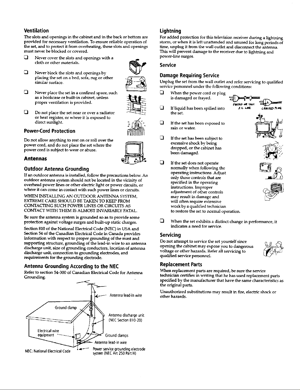
Antenna Grounding According to the NEC
Refer to section 54-300 of Canadian Electrical Code for Antenna
Grounding.
_ Antenna lead-in wire
Lightning
For added protection for this television receiver during a lightning
storm, or when it is left unattended and unused for long periods of
time, unplug it from the wall outlet and disconnect the antenna.
This will prevent damage to the receiver due to lightning and
power-line surges.
Service
Damage Requiring Service
Unplug the set from the wall outlet and refer servicing to qualified
service personnel under the following conditions:
_l When the power cord or plug
is damaged or frayed.
FI If liquid has been spilled into
the set.
If the set has been exposed to
rain or water.
FI [f the set has been subject to
excessive shock by being
dropped, or the cabinet has
been damaged.
If the set does not operate
normally when following the
operating instructions. Adjust
only those controls that are
specified in the operating
instructions. Improper
adjustraent of other controls
may result in daraage and
will often require extensive
work by a qualified technician
to restore the set to normal operation.
FI When the set exhibits a distinct change in performance, it
indicates a need for service.
<
.//
Servicing
Do not attempt to service the set yourself since _ ,,_
opening the cabinet may expose you to dangerous
voltage or other hazards. Refer all servicing to
qualified service personnel.
Replacement Parts
When replacement parts are required, be sure the service
technician certifies in writing that he has used replacement parts
specified by the manufacturer that have the same characteristics as
the original parts.
Unauthorized substitutions may result in Ftre, electric shock or
other hazards.
/
NEC:National Electrical Code
Antenna discharge unit
(NECSection810-20)
round clamps
lead-in wire
_ Powerservicegroundingelectrode
system(NECArt 250 PartH)

Safety Check
Upon completion of any service or repairs to the
set, ask the service technician to perform routine
safety checks (as specified by the manufacturer) to
determine that the set is in safe operating
condition, and to so certify. When the set reaches
the end of its useful life, improper disposal could
result in a picture tube implosion. Ask a qualified
service technician to dispose of the set.
For Safety
Be careful when moving the projection TV
When you place the projection TV in
position, be careful not to drop it on your
foot or fingers.
Watch your footing while installing the
projection TV.
Carry the projection TV in the specified manner
If you carry the projection "IV in a manner
other than the specified manner and
without the specified number of persons, it
may drop and a serious injury may be
caused. Be sure to follow the instructions
mentioned below.
F1 Carry the projection TV with the
specified number of persons (see
page 10).
Do not can'y the projection TV holding the speaker grill.
Hold the projection TV tightly when carrying it.

Contents
Introducing the Projection TV
Overview ....................................................... 1
Features .......................................................... 2
Package Contents ......................................... 3
Using the Remote Control ........................... 3
Frequently Asked Questions ...................... 7
Setting Up the Projection TV
Overview ....................................................... 9
Carrying Your Projection TV .................... 10
Installing the Projection TV ...................... 10
Mounting the Rear Speakers
(not supplied) ....................................... 11
Projection TV Controls and Connectors.. 13
Basic Connections ....................................... 17
Connecting a VCR and Cable ................... 19
Connecting a VCR and Cable Box ............ 20
Connecting Two VCRs for Tape Editing 22
Connecting a Satellite Receiver ................ 23
Connecting a Satellite Receiver
with a VCR ........................................... 24
Connecting an Audio Receiver ................. 25
Connecting a DVD Player with
Component Video Connectors .......... 26
Connecting a DVD Player with A/V
Connectors ............................................ 27
Connecting a Camcorder ........................... 28
Connecting a Device with an
Optical IN Connector .......................... 29
Connecting i.LINK Compatible Devices.30
Using the CONTROL S Feature ............... 34
Setting Up the Projection TV
Automatically ...................................... 35
Adjusting the Convergence
Automatically (Flash Focus) .............. 36
Using the Projection TV Features
Overview ..................................................... 37
Using the Program Guide ......................... 38
Using the Scrolling Channel Index .......... 39
Using Favorite Channels ........................... 40
Using Wide Screen Mode .......................... 43
Using Twin View ........................................ 44
Using the Freeze Function ........................ 47
Using the i.LINK Control Panel ............... 48
Using the Timer .......................................... 49
Using the Projection TV Menus
Overview ..................................................... 51
Using the Video Menu ............................... 52
Using the Audio Menu .............................. 54
Using the Screen Mode Menu .................. 56
Using the Channel Setup Menu ............... 58
Using the Parental Control Menu ............ 60
Using the Setup Menu ............................... 64
Other Information
Overview ..................................................... 67
Programming the Remote Control .......... 68
Operating Other Components with Your
Projection TV Remote Control .......... 71
About i.LINK .............................................. 73
Troubleshooting .......................................... 74
Specifications ............................................... 77
Index ............................................................. 79

Overview
This chapter gives an overview of the projection TV features, defines
the package contents, describes the remote control, and provides
answers to frequently asked questions,
Topic Page
Features 2
Package Contents 3
Using the Remote Control 3
Frequently Asked Questions 7
1
Introducing the Projection TV
l eatures
Some of the features that you will enjoy with your new projection TV
include:
[] Built-in Digital Television (DTV) Receiver: You can watch
digital television programs and enjoy the improved audio/video
quality that these programs offer.
Wide Screen Mode: Watch conventional 4:3 aspect ratio
broadcasts in wide screen (16:9) mode.
[] DRC TM Multi-Function: Unlike conventional line doublers, the
DRC (Digital Reality Creation) feature doubles vertical and
horizontal lines, resulting in four times the density for quality
sources such as DVD, satellite, and digital camcorder.
O Twin ViewTM: Using the Multi-Image Driver (MIDX), Twin View
allows you to watch two programs side by side, with the ability
to zoom in one picture. You can watch pictures from two different
sources (1080i, 720p, 480p, and 480i) simultaneously.
O Program Guide: Lets you select digital channels and subchannels
and review program information from an on-screen list.
[] Scrolling Channel IndexTM: Lets you preview and select
programs from a scrolling index of video pictures.
[] Favorite Channels: Allows you to preview and select from 16 of
your favorite channels.
[] Parental Control: V-Chip technology allows parents to block
unsuitable programming for younger viewers.
[] Component Video Inputs: Offers the best video quality for DVD
(480p, 480i), and digital set-top box (1080i, 720p, 480p, 480i)
connections.
O S-VIDEO Inputs: Provides a high-quality video signal from
connected equipment.
O CineMotionTM: Provides optimal picture quality for film-based
sources (media originally shot in 24 frames-per-second format).
[] i.LINK: Provides a secure digital interface to other digital home
entertainment devices, including digital cable set-top boxes.
i.LINK allows for the secure transfer of copyright-protected high-
definition content between these devices and your digital
television.
2
[] Dolby ® Digital: This TV has a Dolby Digital decoder. By adding
rear speakers and a powered subwoofer, you can enjoy 5.1
channel surround sound from Dolby Digital encoded DTV
programs.
Optical Digital Audio Out: If you have an audio receiver with an
optical digital audio input, you can use it to decode and amplify
the optical digital audio output.
Package Contents
Along with your new projection TV, the package contains a remote
control and two AA batteries. No additional cables are included.
These items are all you need to set up and operate the projection TV
in its basic configuration.
Most components (VCRs, DVD players, etc.) come with the necessary
cables to connect them. If you want to set up a complex system, you
may need to buy extra cables, connectors, etc. Be sure to have these
on hand before you start to connect your system.
Using the Remote Control
Although some of the projection TV's functionality can be controlled
using buttons located on the front panel of the projection TV (see
page 13), you'll find the remote control to be more convenient while
watching TV.
Introducing the Projection TV
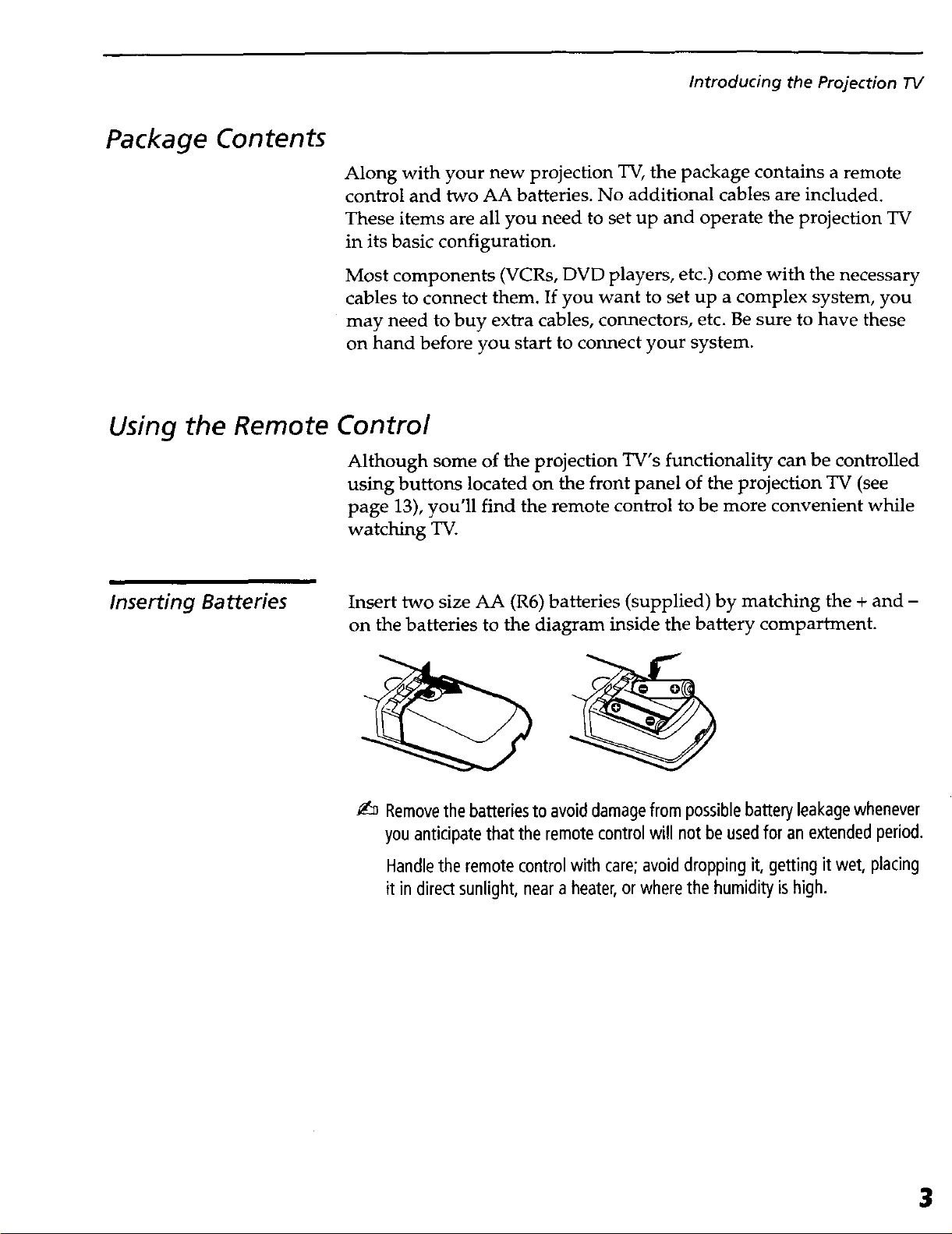
Inserting Batteries Insert two size AA (R6) batteries (supplied) by matching the + and -
on the batteries to the diagram inside the battery compartment.
_:_ Removethe batteriesto avoid damagefrom possiblebattery leakagewhenever
you anticipate that the remote controlwill not be usedfor an extendedperiod.
Handlethe remote control with care;avoid dropping it, getting it wet, placing
it in direct sunlight, near a heater, orwhere the humidity is high.
3
Introducing the Projection IV
Button Descriptions
_ __M_NG 8LEE
[__ -_
IO®
SONY
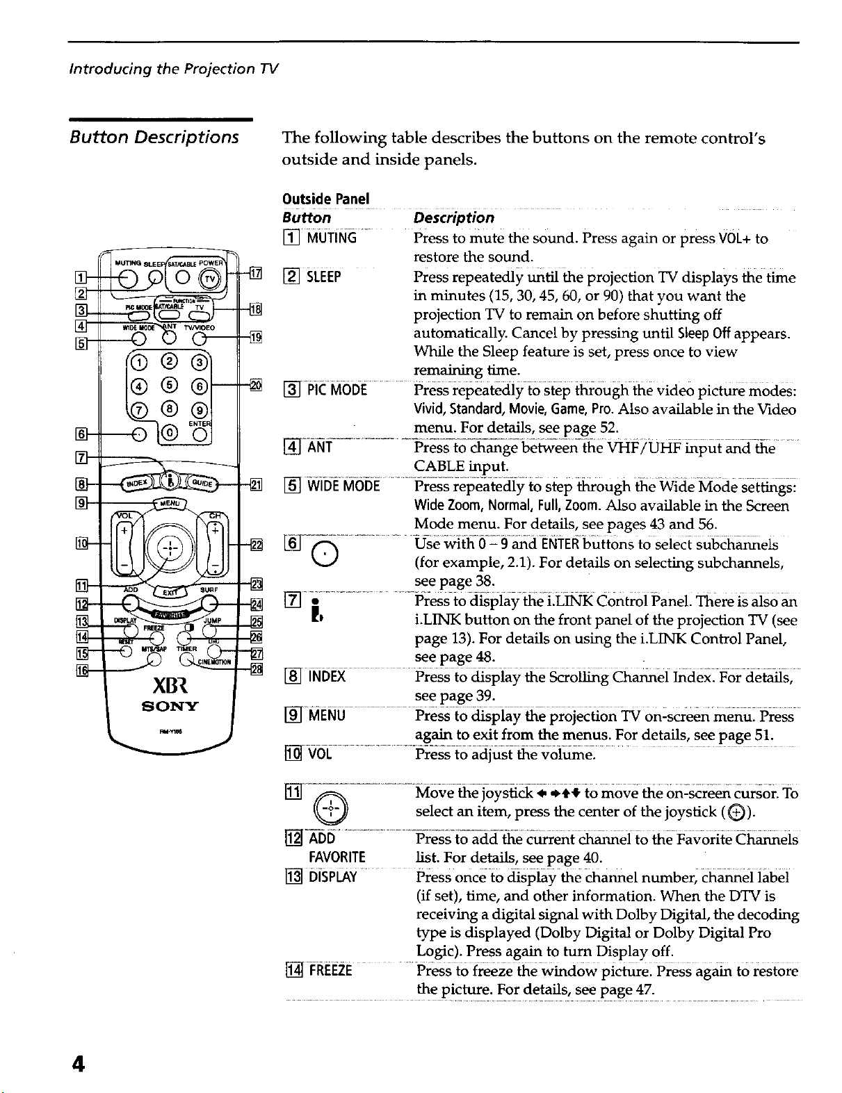
The following table describes the buttons on the remote control's
outside and inside panels.
Outside Panel
Button Description
[] MUTING
[] SLEEP Press repeatedly _til the projection TV displays the time
[] PICMODE Press repeatedly to step through the video picture modes:
1_] AI_i:-.................... Pre_-_ge be_een- the _F/UHF _put _d-_e ........
Press to mute the sound. Press again or press V0L+ to
restore the sound.
in minutes (15, 30, 45, 60, or 90) that you want the
projection TV to remain on before shutting off
automatically. Cancel by pressing until Sleep Off appears.
While the Sleep feature is set, press once to view
remaining time.
Vivid, Standard, Movie, Game, Pro.Also available in the Video
menu. For details, see page 52.
CABLE input.
[]WitiE MbeE..............Press repeatediy to Step '_0ugh _e Wide Mode-s-et_gsi
Wide Zoom, Normal, Full, Zoom. Also available in the Screen
Mode menu. For details, see pages 43 and 56.
_Q ........................Usewi_-i_-Z 9 _cl ENTEI_butt0ns to Select sul_a_eis
(for example, 2.1). For details on selecting subchannels,
see page 38.
]ff]_ ............... idresst0 d_piay _e LL_K Control Panel There is aiso
_l i.LINK button on the front panel of the projection TV (see
page 13). For details on using the i.LINK Control Panel,
see page 48.
[] iNDEX Press to clispiay _e _r0i_g ch_ei _aex: For deta_s,
see page 39.
[_] MENU Press to _spiay 6e pro]ec_on _ 0nZscreen menu: Press
again to exit from the menus. For details, see page 51.
[] VOL .................. Press to adjust 6e voi_e2 .....
select an item, press the center of the joystick (_)).
[]-ADD P-re-ss-to--a-d_d_eC_rrent _ei to _e Favorite Ch_eis
FAVORITE list. For details, see page 40.
[] DISPLAY.... Press once to display the channel number, ch_ei iabei
(if set), time, and other information. When the DTV is
receiving a digital signal with Dolby Digital, the decoding
type is displayed (Dolby Digital or Dolby Digital Pro
Logic). Press again to turn Display off.
[] I:REr:zE ...... Press t6froze wind6wpiCerel Press aga_ to restore
................. the p!cture. F0r details, see page 47.
4
Introducing the Projection "IV
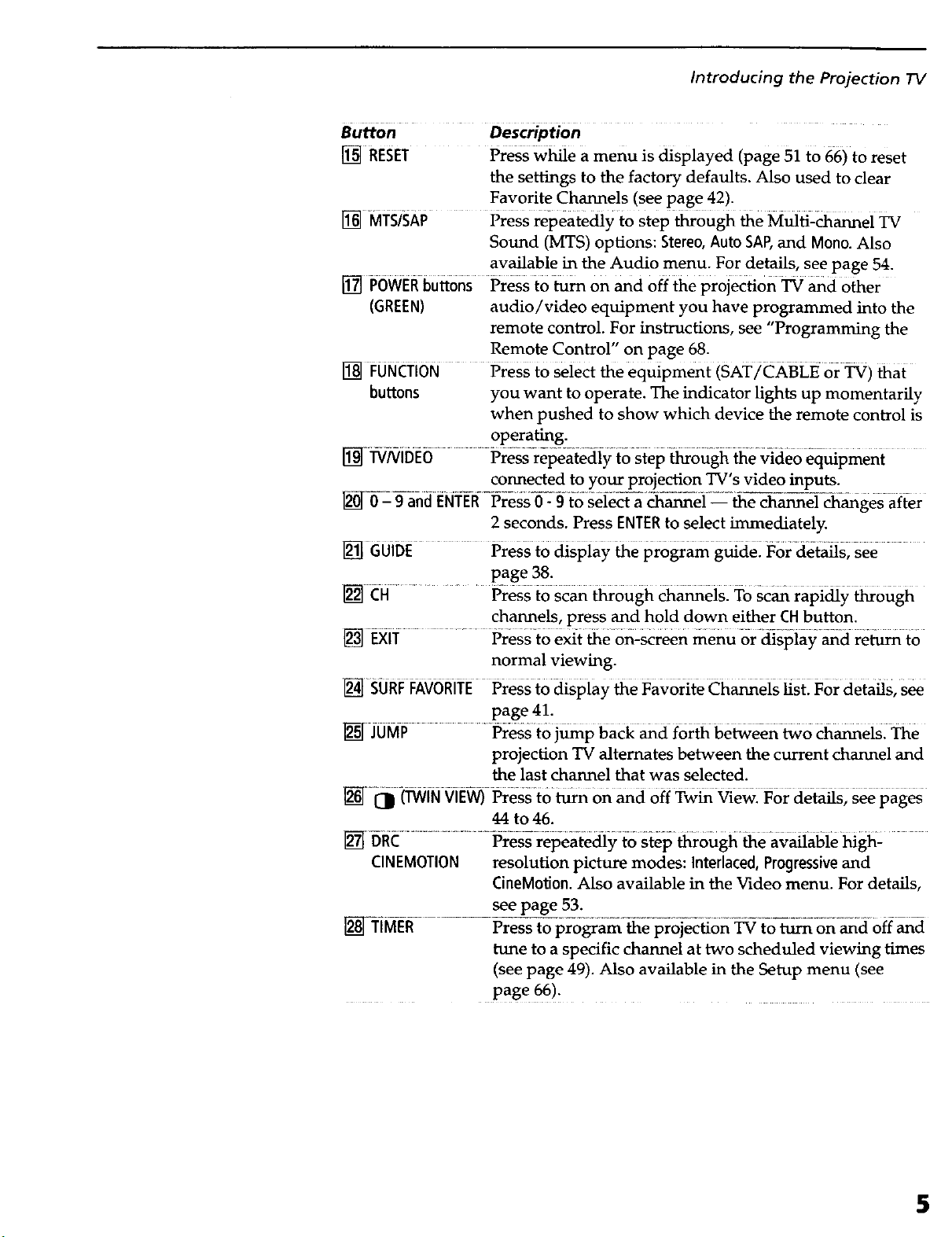
Button Description
I_ RESET Press w_e a menu is displayed (page 51 to 66) to reset
the settings to the factory defaults. Also used to clear
Favorite Channels (see page 42).
[] MTS/SAP Press repeatedly t0 step _ough _e Mulfi2_ei TV
Sound (MTS) options: Stereo, Auto SAP, and Mono. Also
available in the Audio menu. For details, see page 54.
[] PowER buttons Press to _rn on and off the projection TV and other
(GREEN) audio/video equipment you have programmed into the
remote control. For instructions, see "Programming the
Remote Control" on page 68.
[] FUNO'i0N Press tO Select the equipment (SAT/CKBLE or _) _at
buttons you want to operate. The indicator lights up momentarily
when pushed to show which device the remote control is
operating.
[_J "I:_iNil)E6 .......... Pressrei_eatedi f to Step t_ough 6e video eq_pment
connected to your projection TV's video inputs.
2 seconds. Press ENTERto select immediately.
[] GUIDE PreSs to dispiay 66 program g_de: For detaOs, see
page 38.
[] CH .......... Press to scan through channels. To Scan rapidly through
channels, press and hold down either CHbutton.
[] EXi'r ............ Pressto ex{t the 0n:screen menu or diSpla}; and re_ to
normal viewing.
I_ SURFFAV6RrIE Press to dispiay _e Favorite Ch_eis _Stl For details, S_
page 41.
[] JUMP ........Press to j_p bacE _d for6 be_een _o _eisl _e
projection TV alternates between the current channel and
the last channel that was selected.
[]l_ (TWIN VIEW) Press to _n on _d off Tw_ _ewl For deta_s; S_ pages
44 to46.
[] DIiC .......................................Press repeate_y to stei_ _ough 6e available _gh:
CINEMOTION resolution picture modes: Interlaced, Progressive and
CineM0tion. Also available in the Video menu. For details,
see page 53.
..............................Pr XKopr6 am- ebr ecidon on d
tune to a specific channel at two scheduled viewing times
(see page 49). Also available in the Setup menu (see
page 66).
5
Introducing the Projection TV
0oo®
_2
_ •
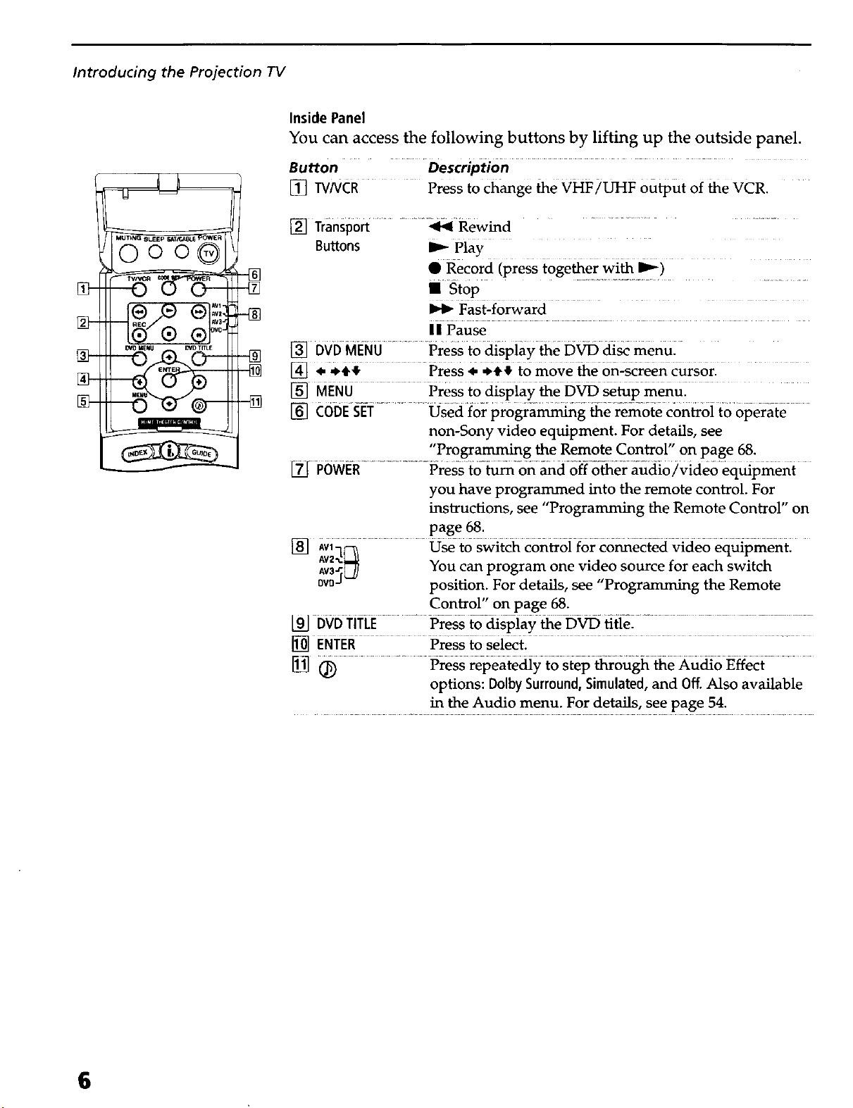
Inside Panel
You can access the following buttons by lifting up the outside panel.
Button Description
[] WNCR ..... Press to change be VHF/UHF output of the VCR.
[] Transport ......... _ Rewind
Buttons I_ Play
• Record (press together with I_)
II st0p ............................................
Fast-forward
II Pause
[] DVD MENU...... Press to _spiay 6e D_ _ menul
[] • .+_ Press. *+} to move 6e on-screen c_s6rl
[] MENU Press to dispiay 6e D_ se6p mend;
[] €0DES_ET................Osed1orpr0gra_g 6e f6mote€on_oito 6perate
non-Sony video equipment. For details, see
"Programming the Remote Control" on page 68.
POWE-R.....................Press ;cO-_-on _doff other audio/video equipmeni
you have programmed into the remote control. For
instructions, see "Programming the Remote Control" on
page 68.
[] a6q_ O_ t6 Swit_ controi f6r c6_ected video eq_pmentl
aaW_ You can program one video source for each switch
0v0d position. For details, see "Programming the Remote
Control" on page 68.
[91-DvD"riT-iJE...................Press _display _e-D-_ title-.................................................................
[] ENTER Press to Seiect.
1_ _ Press repeatediy to Step6r6ugh 6e £u_o F_ffect
options: Dolby Surround, Simulated, and Off. Also available
in the Audio menu. For details, see page 54.
6
Frequently Asked Questions
Introducing the Projection TV
What is digital TV
(DTV)
What are the
benefits of DTV?
Digital television (or "DTV") refers to the over-the-air television
broadcast standards adopted by the Federal Communications
Commission in 1996. Developed by the Advanced Television Systems
Committee (ATSC), a group of manufacturing companies, these
standards define the specifications for 18 digital broadcast formats.
There are six formats in the ATSC DTV standard that are described as
"High Definition Television." The remaining 12 video formats are
described as "Standard Definition Television."
Although the technical aspects of these standards are transparent to
television viewers, the benefits are as dramatic as those experienced
when digital music on compact disk was introduced -- probably
even more so.
Your Sony projection TV is capable of receiving all 18 formats of
digital TV formats, including high-definition.
For the television viewer, digital TV represents one of the most
significant advances in television since color television replaced black
and white. Here are just a few of the benefits:
Do I need a special
antenna to receive
digital television ?
Dramatically superior picture quality, with up to six times the
picture detail of today's analog television.
O
Multichannel digital sound, including Dolby ® Digital sound.
O
Widescreen. DTV can provide the same type of widescreen
presentation as you see in movie theaters. The new screen size
has a 16:9 width-to-height (or "aspect") ratio, compared with a
4:3 aspect ratio of today's conventional television. This means
that digital broadcasts of movies no longer need to be
"reformatted" for television.
No. Initially, digital television will arrive through a standard, over-
the-air VHF/UHF antenna, which means you can receive digital
broadcasts using the same terrestrial ("rooftop") antenna you
currently use to receive conventional programming. However, if you
currently receive your VHF/UHF programming via cable, you will
need to install a VHF/UHF antenna in order to receive digital
programming. Your Sony projection TV, however, is also equipped
with connectors that may allow you to connect DTV-compafible cable
boxes when they become available.
7

Introducing the Projection TV
Can this TV receive
conventional analog
broadcasts that are
available today?
When is digital
broadcasting being
introduced?
How can I select
digital channels ?
Yes. This TV is designed to receive conventional analog broadcasts,
cable TV, as well as all formats of digital broadcasts. Of course, you
can also connect VCRs, DVD players, digital broadcast (satellite)
receivers, and other audio/video components.
The transition from today's analog broadcasting system to digital
television will take time to complete. In the fall of 1998, some
networks started to broadcast digital programs.
Digital channels are indicated by the use of a decimal or "dot" in the
subchannel number (for example, "2.1"). This number appears when
you press the CH+/- buttons or press the DISPLAYbutton. To select a
subchannel directly, use the 0-9 buttons, Q button, and the ENTER
button.
For example, to select subchannel 2.1, press:
Q + O + (_) + ENTER
You can also select digital channels using an on-screen program
guide. See page 38 for details.
8
Overview
This chapter includes illustrated instructions for setting up your
projection TV.
Topic Page
Carry_g Your Projection _ 10
Installing the Projection TV 10
Moun6ng _eRear Speakers inot supplied) 1i
Basic Connections 17
Connecting a VCR and Cable 19
Connecting a VCR and Cable Box 20
Connecting Two VCRs for Tape Editing 22
Connecting a Satellite Receiver 23
Connecting a Satellite Receiver with a VCR 24
Connecting an Audio Receiver 25
Connecting a DVD Player with Component Video 26
Connectors
Connecting a DVD Player with A/V Connectors 27
Connecting a Camcorder 28
Connecting a Device with an Optical IN Connector 29
Connecting i.LINK Compatible Devices 30
Using the CONTROL S Feature 34
Setting Up the Projection TV Automatically 35
Adjusting the Convergence Automatically (Flash Focus) 36
9
Setting Up the Projection TV
Carrying Your Projection TV
Carrying the projection TV requires three or more people.
The projection TV is equipped with casters for easy movement on a
hard surface. Be sure to move your projection TV using the casters.
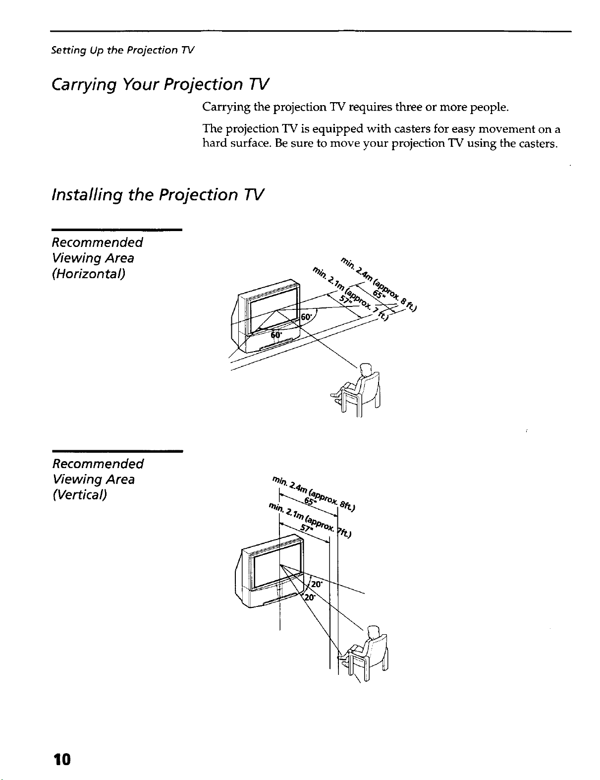
Installing the Projection TV
Recommended
Viewing Area
(Horizontal)
Recommended
Viewing Area
(Vertical)
10
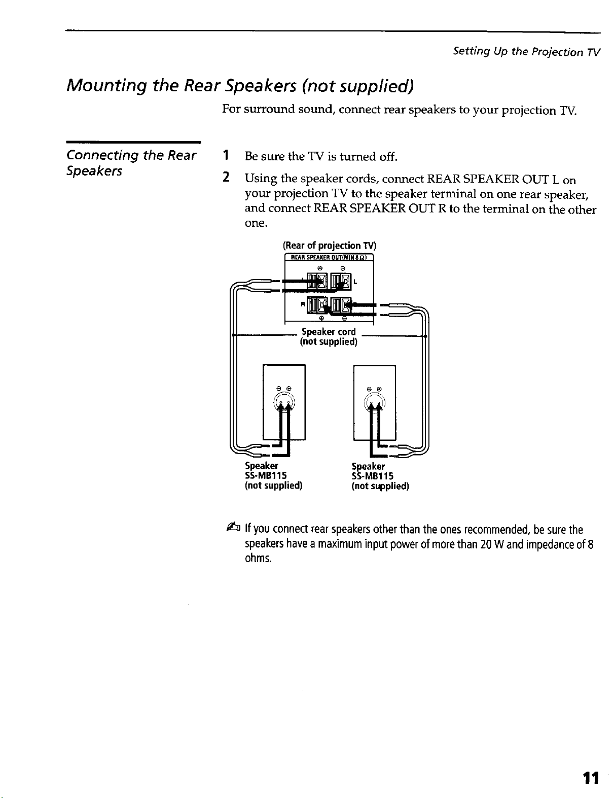
Mounting the Rear Speakers (not supplied)
For surround sound, connect rear speakers to your projection TV.
Setting Up the Projection TV
Connecting the Rear 1
Speakers 2
Be sure the TV is turned off.
Using the speaker cords, connect REAR SPEAKER OUT L on
your projection TV to the speaker terminal on one rear speaker,
and connect REAR SPEAKER OUT R to the terminal on the other
one.
(Rearof projection"rv)
Speaker cord
(not supplied)
Speaker
SS-MB115
(not supplied)
Speaker
SS-MB115
(not supplied)
If you connect rearspeakersother than the onesrecommended, besurethe
speakershavea maximum input power of morethan 20 W and impedanceof 8
ohms.
11
Setting Up the Projection TV
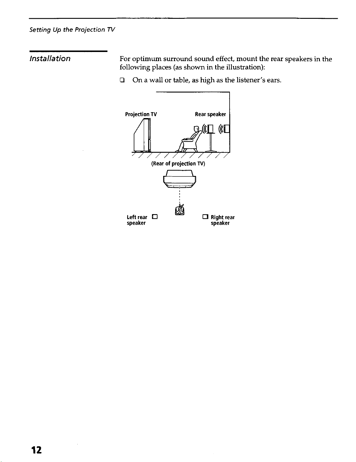
Installation
For optimum surround sound effect, mount the rear speakers in the
following places (as shown in the illustration):
On a wall or table, as high as the listener's ears.
Projection TV Rear speaker
(Rear of projection TV)
i
i
Left rear []
speaker
I-IRightrear
speaker
12

Projection TV Controls and Connectors
Setting Up the Projection TV
Front Panel
To access the front buttons and input jacks on the projection TV, push
in to release the door on the front of the projection TV.
J
POWI_R
sTza_ _1
LUI_ _ANO If
O
[]
O
[] I--
Push to open
Control Description
[] POWER Press to turn on and off _e projection TV.
F_ 'STANDBY/ ............... _en _tin orange; _dicates_ti:L_ Stanci6y is6n: _en_t _red'
i.LINKSTANDBY indicates that i.LINK Standby is Off. For details, see page 66.
TIMER..................... _'enli[: _dicates one of-_e-t_ers is set: For €letails:-see page 49: .......
[] MENU Press to display the projecti0n TV on-screen menul Press again to exit from
the menus. For details, see page 51.
[] i:Li6K Press 6 aspiay 6e i:_ Con_oi P_ei: For detaas on us6g 6e i:L_k
Control Panel, see page 48.
_, '4# ...................... Press _, ,_*# tomoveme0nL-_reen_soranapresssELECTioseiect.
5ELE_ ........................ iar--esst o _iect- th-e-on-scr--een_-gidigilteditem_ ...................................................
_ --WNI--DEO.......................................-P_ssre----peat--ecl--ly to stepthro-------ugh_--e--vid---eo-equi_-co_ted to yo_ .....
projection TV's video inputs.
[] :CHANNEL+ ..... Press to Scan tl_rough Ch_eis_ ..............
[] :VOLUME+ ....................Press to adjust 6e voi_el ..........
FLASHFOCUS Press to acijust _e Convergence (see page 36). ......
13
Setting Up the Projection TV
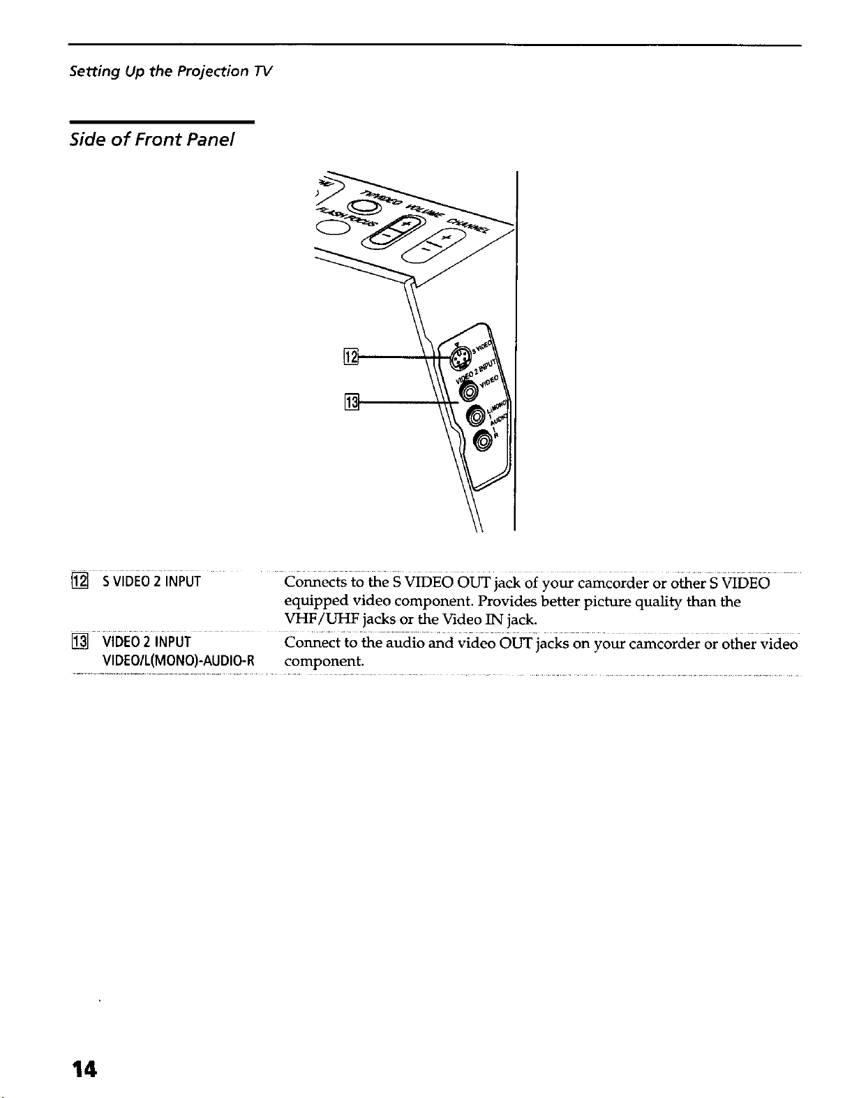
Side of Front Panel
[]
[] S VIDEO2iNPUT Connects to the S VIDEO OUT jack of your camcorder or o_er S VIDEO
equipped video component. Provides better picture quality than the
VHF/UHF jacks or the Video IN jack.
[] Vi6E62 i6PUT Co_ect to the audio and video OUTiac_ on your camcorder or other Video
VIDEO/L(MONO)-AUDIO-R component,
14
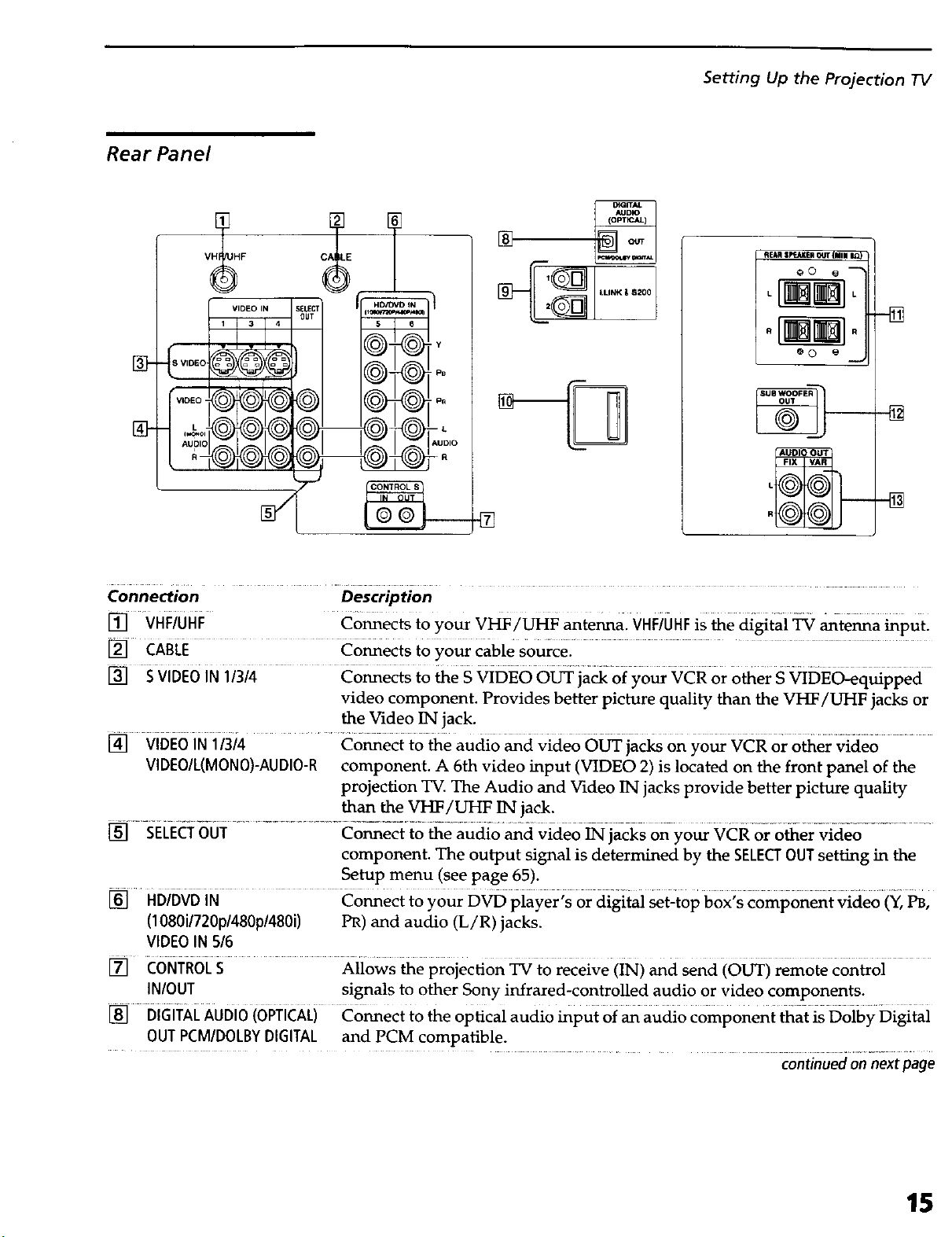
Rear Panel
VH_HF
DtGITAL
AUDIO
Setting Up the Projection TV
AEAR SpcJLKER OUT {lillll IL_
O0 O --
.aS
Y
"VIDEO
oo o_._
lZloo,o
J
Connection Description
[] VHFiuHF Connects to your VHF/UHF antenna. VHFiUHFis the digital _ antenna input.
[] CABLE Co_ects to your cable Sourcel .....................
[] S vIDEO IN 11314 Co_ects t0 the S _DEO O_ ja_ oi your vcR or Other SviDE_quipped
video component. Provides better picture quality than the VI-_/UHF jacks or
the Video IN jack.
[] VIDEO IN 1/3/4 Connect to the audio and video OUT jacks on your VCR or other video
VIDEO/L(MONO}-AUDIO-R component. A 6th video input (VIDEO 2) is located on the front panel of the
projection TV. The Audio and Video IN jacks provide better picture quality
than the VHF/UHF IN jack.
_] --SELEcTo01 .......... Co_e_ io _e audio an{i video _]acks on-y0_ VCRor other--video .........
component. The output signal is determined by the SELECTOUT setting in the
Setup menu (see page 65).
HDiGvDiN co_ect to your D_ piayer;s or digital _t-t0p box;s component video (Y, _'
(1080i/720p/480p/480i) PR) and audio (L/R) jacks.
VIDEO IN 5/6
-N
[] CONTROLS Allows the projection _ to r_eive (iN) and Send (OF) remote control
IN/OUT signals to other Sony infrared-controlled audio or video components.
[] DIGITALAUDIO(OPTICAL) Connect to the optical audio input of an audio component that is Dolby Digital
OUT PCMIDOLBYDIGITAL and PCM compatible.
continued on next page
15
Setting Up the Projection 73/
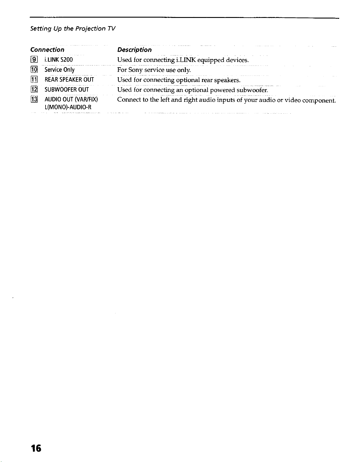
Connection Description
[] i.LINK$200 Used for connecting i.LINK equipped devices.
[] sewice 0niy For Sony service u_ o_y.
[] REARSPEAKEROUT Used for connecting optional rear speakers.
[] sUBWOOFERout used for C0nnecfing_ opti0nal powered subw00fer. ....
[] AUDIO007 ivA_Fix) connect to the left and right audio inputs 0f your audio or video component.
L(MONO)-AUDIO-R
16
Basic Connections
Setting Up the Projection TV
This section describes how to connect a VHF/UHF antenna, CATV
cable, and CATV cable box.
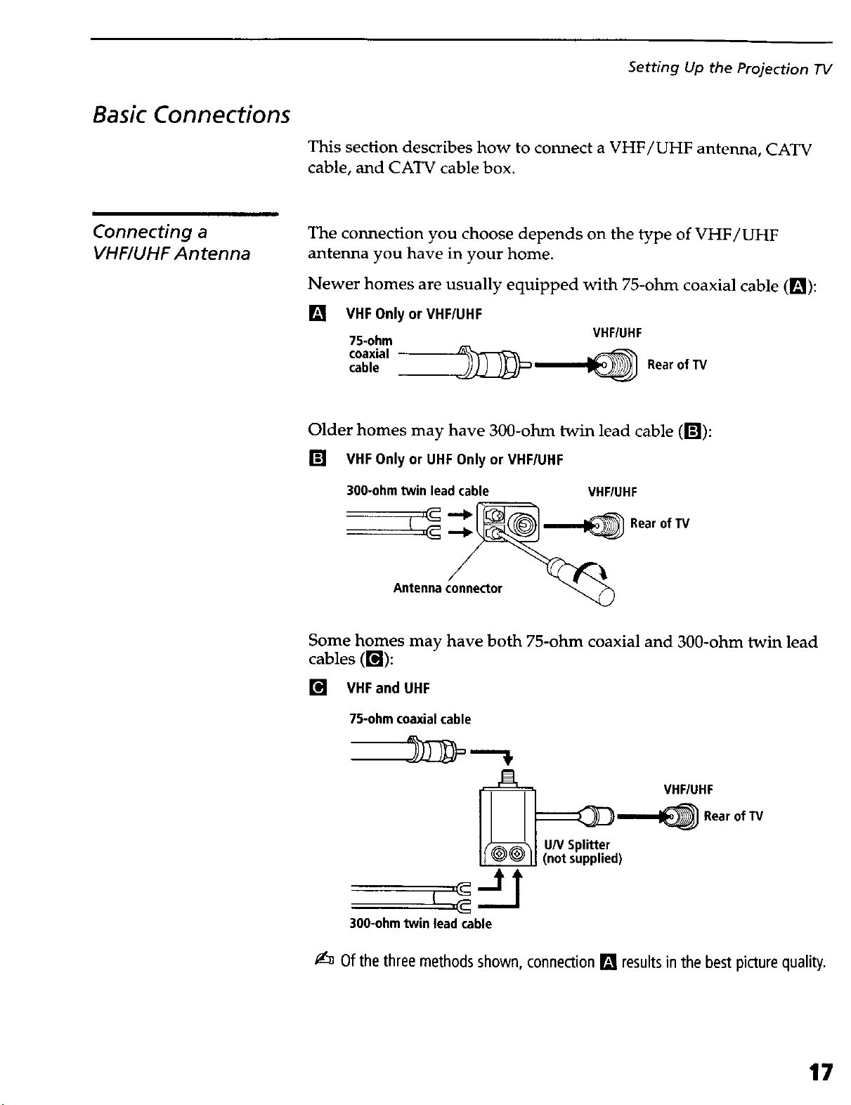
Connecting a
VHF/UHF Antenna
The connection you choose depends on the type of VHF/UHF
antenna you have in your home.
Newer homes are usually equipped with 75-ohm coaxial cable ([]):
[]
VHF Only or VHF/UHF
75-ohm
cable
coaxial _=__
VHF/UHF
Rear of TV
Older homes may have 300-ohm twin lead cable (r_):
[] VHFOnlyor UHFOnly or VHF/UHF
300-ohm twin lead cable
Antenna connector
VHFIUHF
Rearof TV
Some homes may have both 75-ohm coaxial and 300-ohm twin lead
cables ( r_l ):
[] VHFand UHF
75-ohm coaxialcable
VHF/UHF
Rear of "rv
U/VSplitter
(not supplied)
300-ohm twin lead cable
_:_ Of the threemethods shown, connection [] resultsin the best picture quality.
17
Setting Up the Projection TV
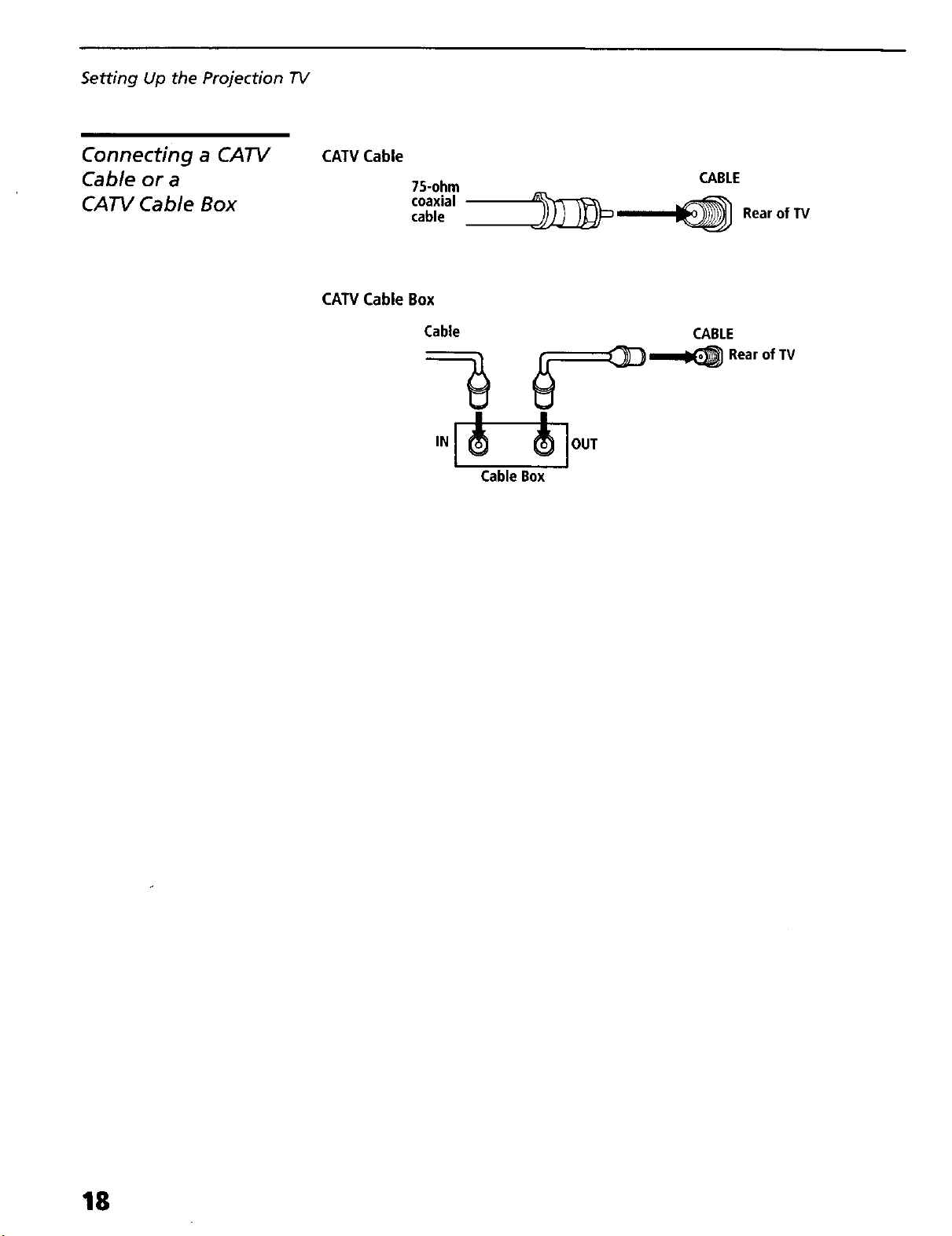
Connecting a CATV
Cable or a
CATV Cable Box
CATV Cable
75-ohm
coaxial
cable
CATV Cable Box
Cable
IN
|
CableBox
CABLE
__ RearofTV
CABLE
_1_ Rearof TV
l
lOUT
18
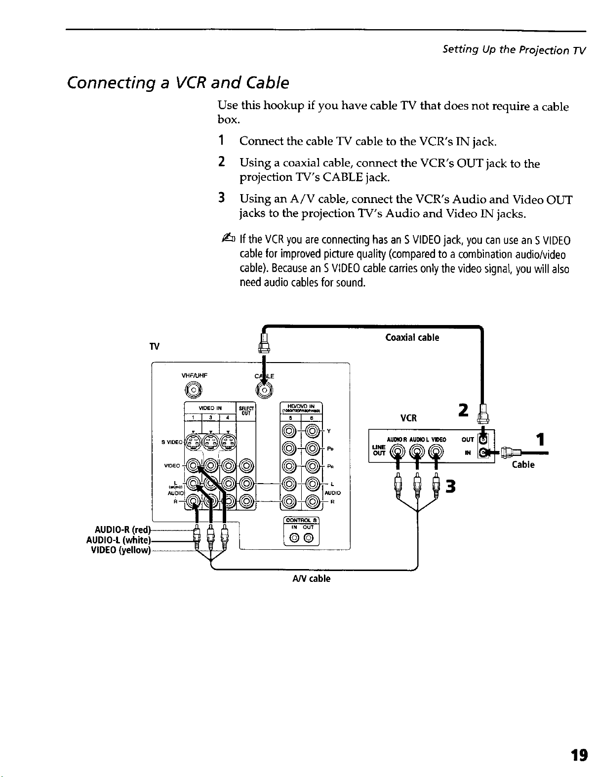
Connecting a VCR and Cable
Use this hookup if you have cable TV that does not require a cable
box.
1 Connect the cable TV cable to the VCR's IN jack.
2 Using a coaxial cable, connect the VCR's OUT jack to the
projection TV's CABLE jack.
3 Using an A/V cable, connect the VCR's Audio and Video OUT
jacks to the projection TV's Audio and Video IN jacks.
If the VCRyou areconnecting hasan SVIDEOjack, you can use an SVIDEO
cablefor improved picture quality (compared to a combination audio/video
cable).Becausean SVIDEOcable carriesonly the video signal, youwill also
needaudio cablesfor sound.
Setting Up the Projection IV
AUDIO-R(red)
AUDIO-L(white)
VIDEO(yellow)
W
VHF/UHF
@
VIDEO IN
C_ ,LE
IY
AN cable
Coaxialcable
VCR
2
1
-- Cable
19
Setting Up the Projection TV
Connecting a VCR and Cable Box
Usethis hookupif
O Your cable TV company scrambles some channels, but not all of
them (pay channels vs. regular cable channels), so you need to
use a cable box
O You want to use the Twin View or Scrolling Channel Index
feature.
With thissetupyou can
O Use the projection TV remote control to change channels using
your cable box when the signal is scrambled.
O Use the projection TV remote control to change channels using
your projection TV when the signal is not scrambled. (Your
projection TV's tuner provides a better signal than the cable box.)
O Use the Twin View and Scrolling Channel Index features.
O Record both regular cable TV and scrambled channels.
Toconnect a cable box and a VCR,you will need
O A small inexpensive device known as a splitter.
O Three short coaxial cables.
O Either a combination audio/video cable, or an S VIDEO cable
and audio cables.
1
Connect the CATV cable to the single (input) jack of the splitter.
2
Use a coaxial cable to connect one of the two output jacks of the
splitter to the projection TV's CABLE jack.
3
Use a coaxial cable to connect the other output jack of the splitter
to the input jack of the cable box.
4
Use a coaxial cable to connect the output jack of the cable box to
the input jack of the VCR.
5
Use the video line (yellow) of a combination audio/video (A/V)
cable to connect the video output jack of the VCR to the video
input jack of the projection TV.
If your VCRhas an SVIDEOjack, you cansubstitute anSVIDEOcablefor
the video line of an AN cable.TheSVIDEOcablewill provide improved
video signal quality.
2O
6 Connect the left (white) and right (red) audio output channels of
the VCR to the respective input jacks on the projection TV.
 Loading...