

Page 1
HISTORY INFORMATION FOR THE FOLLOWING MANUAL:
SERVICE MANUAL
ORIGINAL MANUAL ISSUE DATE: 03/2015
Version Date Subject
1.0 03/2015 Original manual issue.
GN1G CHASSIS
Segment: XM-H
LCD TV
9-888-168-A1
Page 2
SERVICE MANUAL
GN1G CHASSIS
Segment: XM-H
LCD TV
9-888-168-A1
Page 3
MODEL LIST
MODEL COLOR COMMANDER DEST.
KDL-65W850C Black RMT-TX100U (UC2)
US/CND
KDL-65W855C Silver RMT-TX100B (CR1)
COSTA RICA
(ECU)
ECUADOR
(LA8)
CHILE
PERU
VENEZUELA
KDL-65W857C Silver RMT-TX100B (CO1)
COLOMBIA
KDL-75W850C Black RMT-TX100U (UC2)
US/CND
KDL-75W855C Silver RMT-TX100B (BR6)
BRAZIL
MODEL COLOR COMMANDER DEST.
KDL-65W850C, 855C, 857C, 75W850C, 855C
3
Page 4
WARNINGS AND CAUTIONS - ENGLISH
CAUTION
These servicing instructions are for use by qualified service personnel only.
To reduce the risk of electric shock, do not perform any servicing other than that contained in the operating instructions unless you are qualified to do so.
WARNING!!
An isolation transformer should be used during any service to avoid possible shock hazard, because of live chassis.
The chassis of this receiver is directly connected to the ac power line.
CARRYING THE TV
Be sure to follow these guidelines to protect your property and avoid causing serious injury.
• Carry the TV with an adequate number of people; larger size TVs require two or more people.
• Correct hand placement while carrying the TV is very important for safety and to avoid damages.
SAFETY-RELATED COMPONENT WARNING!!
Components identified by shading and mark on the schematic diagrams, exploded views, and in the parts list are critical for safe operation. Replace these components with Sony
parts whose part numbers appear as shown in this manual or in supplements published by Sony. Circuit adjustments that are critical for safe operation are identified in this manual.
Follow these procedures whenever critical components are replaced or improper operation is suspected.
CAUTION ABOUT THE LITHIUM BATTERY
• Danger of explosion if battery is incorrectly replaced. Replace only with the same or equivalent type.
• Outer case broken battery should not contact to water.
KDL-65W850C, 855C, 857C, 75W850C, 855C
4 4
Page 5
WARNINGS AND CAUTIONS - FRENCH
ATTENTION!!
Ces instructions de service sont à l’usage du personnel de service qualifi é seulement.
Pour prévenir le risque de choc électrique, ne pas faire l’entretien autre que celui contenu dans le Mode d’emploi à moins que vous soyez qualifi é faire ainsi.
WARNING!!
Afi n d’eviter tout risque d’electrocution provenant d’un chássis sous tension, un transformateur d’isolement doit etre utilisé lors de tout dépannage. Le chássis de ce récepteur est
directement raccordé à l’alimentation du secteur.
POUR TRANSPORTER LE TÉLÉVISEUR
Tenez compte de ce qui suit pendant l’installation du téléviseur :
• Débranchez tous les câbles avant de transporter le téléviseur.
• Transportez le téléviseur avec le nombre de personnes approprié ; un téléviseur de grande taille doit être transporté par au moins deux personnes.
• Lors du transport du téléviseur, l’emplacement des mains est très important pour votre sécurité, ainsi que pour éviter de causer des dommages.
ALERTE!!
Afi n d’eviter tout risque d’electrocution provenant d’un chassis sous tension, un transformateur d’isolement doit etre utilise lors de tout depannage. Le chassis de ce recepteur est
directement raccorde a l’alimentation du secteur.
ATTENTION AUX COMPOSANTS RELATIFS A LA SECURITE!!
Les composants identifi es par une trame et par une marque sur les schemas de principe, les vues explosees et les listes de pieces sont d’une importance critique pour la securite
du fonctionnement. Ne les remplacer que par des composants Sony dont le numero de piece est indique dans le present manuel ou dans des supplements publies par Sony. Les
reglages de circuit dont l’importance est critique pour la securite du fonctionnement sont identifi es dans le present manuel. Suivre ces procedures lors de chaque remplacement de
composants critiques, ou lorsqu’un mauvais fonctionnement suspecte.
KDL-65W850C, 855C, 857C, 75W850C, 855C
5 5
Page 6
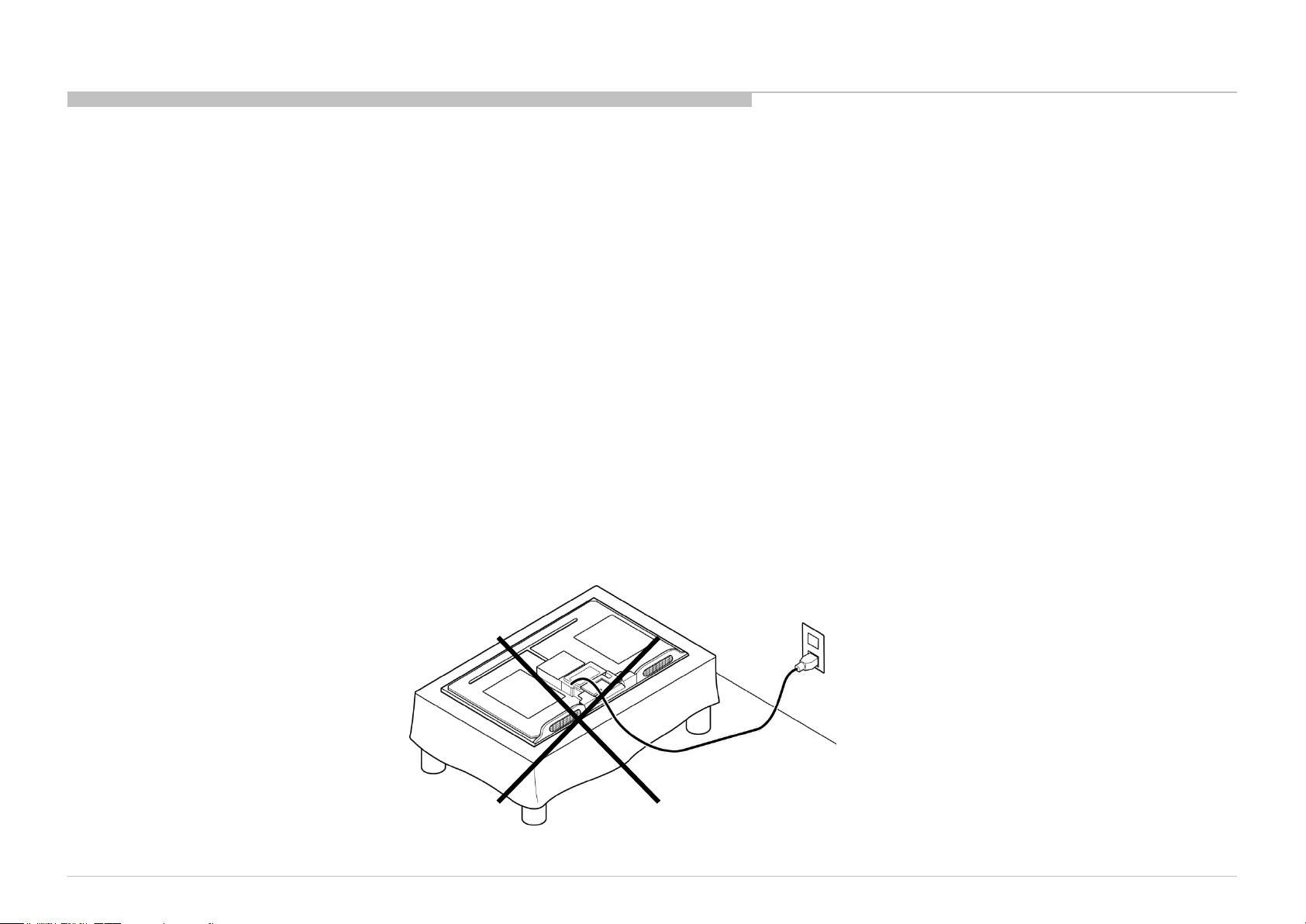
USE CAUTION WHEN HANDLING THE LCD PANEL
When repairing the LCD panel, be sure you are grounded by using a wrist band.
When repairing the LCD panel on the wall, the LCD panel must be secured using the 4 mounting holes on the rear cover.
1) Do not press on the panel or frame edge to avoid the risk of electric shock.
2) Do not scratch or press on the panel with any sharp objects.
3) Do not leave the module in high temperatures or in areas of high humidity for an extended period of time.
4) Do not expose the LCD panel to direct sunlight.
5) Avoid contact with water. It may cause a short circuit within the module.
6) Disconnect the AC power when replacing the backlight (CCFL) or inverter circuit. (High voltage occurs at the inverter circuit at 650Vrms.)
7) Always clean the LCD panel with a soft cloth material.
8) Use care when handling the wires or connectors of the inverter circuit. Damaging the wires may cause a short.
9) Protect the panel from ESD to avoid damaging the electronic circuit (C-MOS).
10) It is recommended not to exceed 1 hour of Power-On nor Burn-in period with LCD panel face down condition, in repair activity.
WARNINGS AND CAUTIONS
KDL-65W850C, 855C, 857C, 75W850C, 855C
6
Page 7

SAFETY CHECK-OUT
After correcting the original service problem, perform the following safety checks before releasing the set to the customer:
1. Check the area of your repair for unsoldered or poorly soldered connections. Check the entire board surface for solder splashes and bridges.
2. Check the interboard wiring to ensure that no wires are “pinched” or touching high-wattage resistors.
3. Check that all control knobs, shields, covers, ground straps, and mounting hardware have been replaced. Be absolutely certain that you have replaced all the insulators.
4. Look for unauthorized replacement parts, particularly transistors, that were installed during a previous repair. Point them out to the customer and recommend their replacement.
5. Look for parts which, though functioning, show obvious signs of deterioration. Point them out to the customer and recommend their replacement.
6. Check the line cords for cracks and abrasion. Recommend the replacement of any such line cord to the customer.
7. Check the antenna terminals, metal trim, “metallized” knobs, screws, and all other exposed metal parts for AC leakage. Check leakage as described below.
8. For safety reasons, repairing the Power board and/or Inverter board is prohibited.
KDL-65W850C, 855C, 857C, 75W850C, 855C
7 7
Page 8
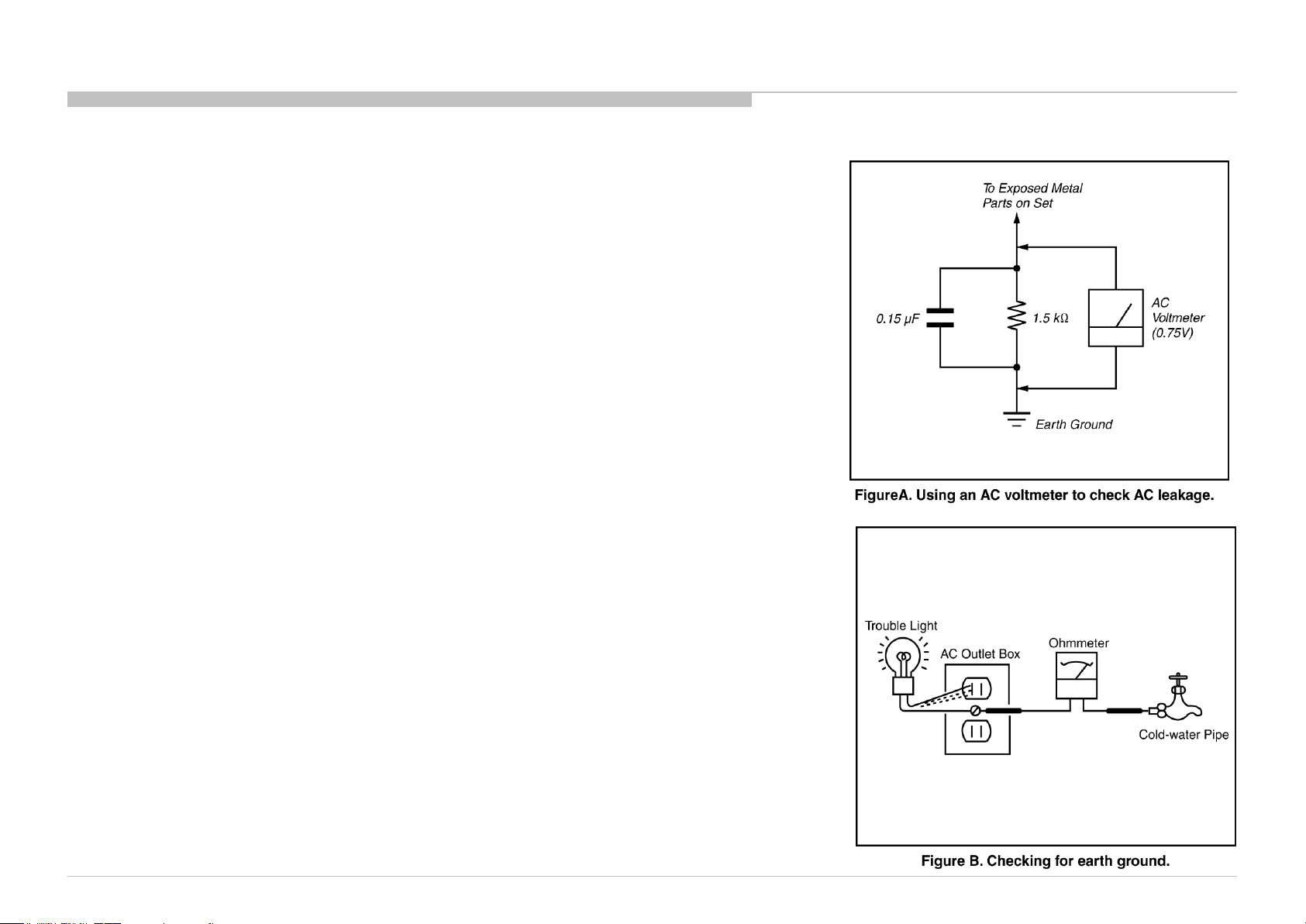
Leakage Test
The AC leakage from any exposed metal part to earth ground and from all exposed metal parts to any exposed
metal part having a return to chassis, must not exceed 0.5 mA (500 microamperes).
Leakage current can be measured by any one of three methods.
1. A commercial leakage tester, such as the Simpson 229 or RCA WT-540A. Follow the manufacturers’
instructions to use these instructions.
2. A battery-operated AC milliampmeter. The Data Precision 245 digital multimeter is suitable for this job.
3. Measuring the voltage drop across a resistor by means of a VOM or battery-operated AC voltmeter. The
“limit” indication is 0.75 V, so analog meters must have an accurate low voltage scale.
The Simpson’s 250 and Sanwa SH-63TRD are examples of passive VOMs that are suitable. Nearly all
battery-operated digital multimeters that have a 2 VAC range are suitable (see Figure A).
How to Find a Good Earth Ground
A cold-water pipe is a guaranteed earth ground; the cover-plate retaining screw on most AC outlet boxes is also
at earth ground.
If the retaining screw is to be used as your earth ground, verify that it is at ground by measuring the resistance
between it and a cold-water pipe with an ohmmeter. The reading should be zero ohms.
If a cold-water pipe is not accessible, connect a 60- to 100-watt trouble- light (not a neon lamp) between the hot
side of the receptacle and the retaining screw. Try both slots, if necessary, to locate the hot side on the line; the
lamp should light at normal brilliance if the screw is at ground potential (see Figure B).
SAFETY CHECK-OUT
KDL-65W850C, 855C, 857C, 75W850C, 855C
8 8
Page 9
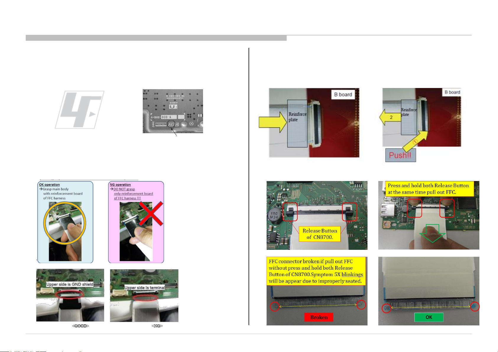
Lead Free Information
The circuit boards used in these models have been processed using Lead Free
Solder. The boards are identified by the LF logo located close to the board
designation.
Figure 4: LF Logo
Figure 5: LF logo on circuit board
Handling the FLEXIBLE FLAT CABLE (FFC)
When you insert / pull out FFC, please grasp a reinforcement board and main
body of FFC
Please hold reinforcement board and plunge
it to depths.
< Insertion>
SAFETY CHECK-OUT
Please pull out FFC while pushing the
button of both ends at the same time.
<Pull out>
KDL-65W850C, 855C, 857C, 75W850C, 855C
9 9
Page 10
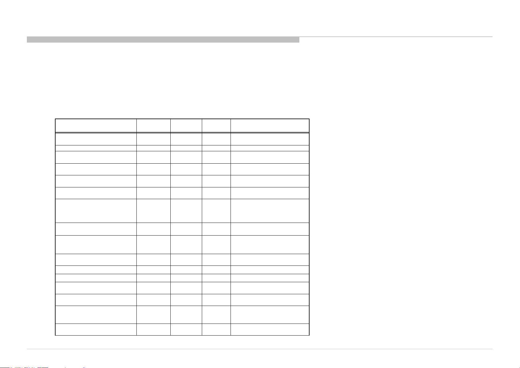
SELF DIAGNOSIS FUNCTION
White Center
Side Amber
( by power saving switch off and *1)
*1 power switch off (by side key)
White looping
Timer/Reminder/REC Timer/Photo
One shot ->
After 5 minutes, side amber LED
( refer to
)
white blinking
white blinking
white blinking
Green /Amber
One shot ->
OUTLINE OF SELF DIAGNOSIS FUNCTION
The units in this manual contain a self-diagnostic function. If an error occurs, the STANDBY LED will automatically begin to flash.
The number of times the LED flashes translates to a probable source of the problem.
A definition of the STANDBY LED flash indicators is listed in the instruction manual for the user’s knowledge and reference.
If an error symptom cannot be reproduced, the remote commander can be used to review the failure occurrence data stored in memory to reveal past problems and how often these
problems occur.
ABOUT ILLUMINAITION LED
STBY/i.LINK STBY/PC STBY
( by remote control off only )
Power ON Animation White
On Timer/Reminder/REC Timer
Software Updating finish White Blue lit Off
REC (SCART REC & HDD
REC/LIVE PAUSE) [AEP/J only]
Status
Power Off
Power On White Off Off
Picture Off
Device Connection White
Sleep Timer/On
Frame
( Power On )
( Deep Standby )
Self Diagnosis Off
Aging mode White
Software Updating
Test Reset White
Error of panel ID White
ePOP/
Shop Illumination
LED
Off Off Off
Off Off Off
White
Off Off Amber
White
White Cyan loop Off
Side RGB
LED
White one
shot
Cyan one
shot
White one
shot
Amber
Lit*2
Red
Blinking
Green
Blinking
Blinking
Red(Pink)
Lit*2
LED
Off
Off
Off
Off *2 One Shot is only user action.
Off
Off Blinking:0.5sec On / 0.5sec Off
Off
Amber
blinking
Off Blinking:0.5sec On / 0.5sec Off
Off *2 One Shot is only user action.
The number of LED blinking
indicates cause of failure
One shot Center White when
Remarks
On
Led Error / Triage chart
feature change
KDL-65W850C, 855C, 857C, 75W850C, 855C
10
Page 11
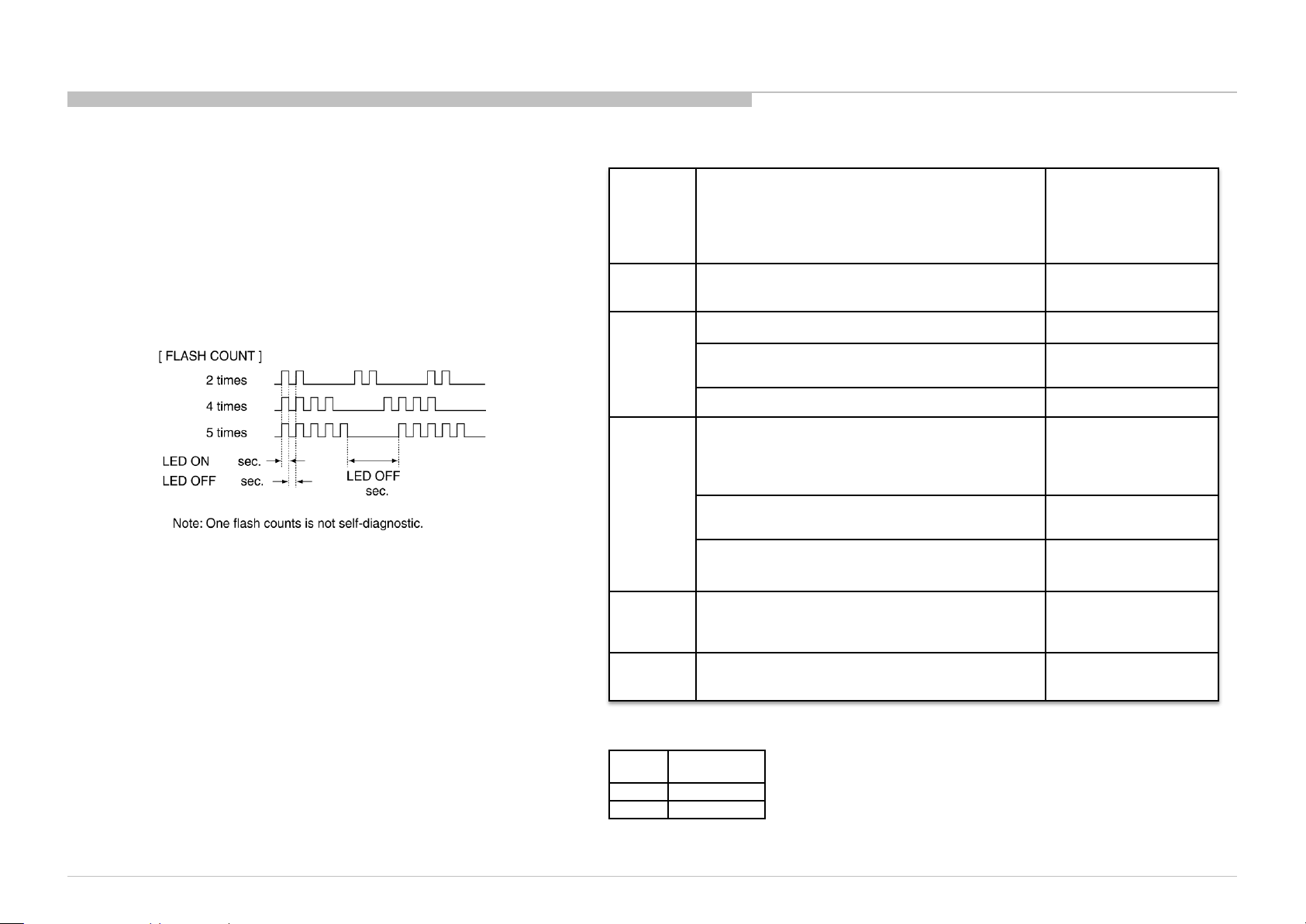
DIAGNOSTIC TEST INDICATORS
G* Board Type
When an error occurs, the STANDBY LED will flash a set number of times
to indicate the possible cause of the problem.
If there is more than one error, the LED will identify the first of the problem
areas.
Result for all of the following diagnostic items are displayed on screen.
If the screen displays a “0”, no error has occurred .
DISPLAY OF STANDBY LED FLASH COUNT
Smart
Core
RED LED
blinking
count
2x
SELF DIAGNOSIS FUNCTION
Detection Items
Main 12V failure [MAIN_POWE]
* This failure is not saved
Main 5.0V failure [DC_ALERT] BMX Board Error
Board Error Item
G** Board Error
BMX Board Error
0.5
0.5
3x
3
5x
6x Backlight failure [BACKLIGHT]
7x
Size
65” GL1SB
75” GL1C
Audio amp. protection [AUD_ERR]
Tuner or demodulator I2C NACK [TU_DEMOD] BMX Board Error
Panel ID EEPROM I2C NACK (Also panel power
failure is a suspect) [P_ID_ERR]
(*detect at startup sequence only)
FRC device I2C No ACK [FRCTC_I2C]
FRC device Initialization failure [FRCTC_I2C]
(*detect at startup sequence only)
Over temperature protection [TEMP_ERR]
Temp. sensor I2C NACK [TEMP_ERR]
BMX Board Error
Speaker
Panel module
Tcon board
G** Board Error
BMX Board Error
Tcon board
Tcon board
Panel module
G** Board Error
BMX Board Error
BMX Board Error
KDL-65W850C, 855C, 857C, 75W850C, 855C
11
Page 12
SELF DIAGNOSIS FUNCTION
SELF-DIAGNOSTIC SCREEN DISPLAY
For errors with symptoms such as “power sometimes shuts off” or “screen sometimes goes out” that cannot be confirmed, it is possible to bring up past occurrences of failure for
confirmation on the screen:
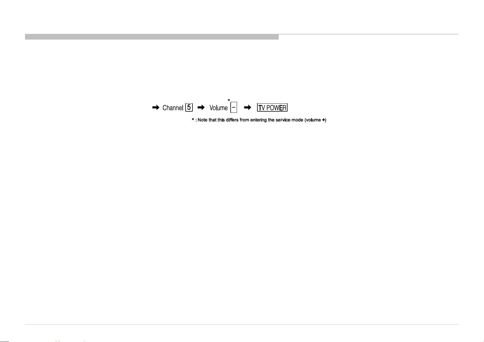
[To Bring Up Screen Test]
In standby mode, press buttons on the remote commander sequentially in rapid succession as shown below:
i+ (info)
Since the diagnostic results displayed on the screen are not automatically cleared, always check the self-diagnostic screen.
After you have completed the repairs, clear the result display to “0”.
Clearing the Self Check Diagnostic List
1. Error history and Error count : Press the Channel 8 => Channel 0 .
2. Panel operation time : Press the Channel 7 => Channel 0 .
Exiting the Self-diagnostic screen
To exit the Self Diagnostic screen, turn off the power to the TV by pressing the POWER button on the remote or the POWER button on the TV.
KDL-65W850C, 855C, 857C, 75W850C, 855C
12
Page 13
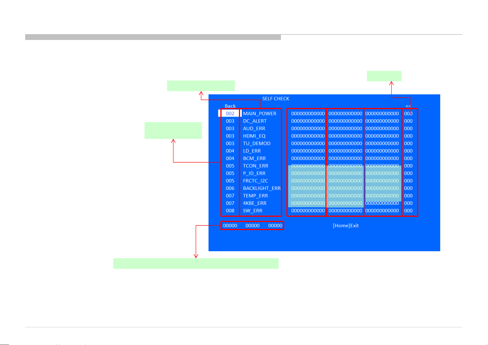
[SELF DIAGNOSTIC SAMPLE SCREEN DISPLAY]
Format of error timestamps
YYMMDDhhmmss (in UTC)
Example:
150823132523 -> Aug 23 2015 13:25:23 UTC
* Only when time is set, an error timestamp
is saved.
Smart Core Red
LED blinking count
SELF DIAGNOSIS FUNCTION
Error count
Error Naming
•Panel Operation Time is recorded every
30 min, but Total Operation Time is recorded every 1 hr.
Therefore, the panel op. time might become larger than the
total op. time.
Total Operation Time [hr] – Boot Count – Panel Operation Time [hr]
KDL-65W850C, 855C, 857C, 75W850C, 855C
Error
timestamp
for last
recorded
error
Error
timestamp
for second
last
recorded
error
Error
timestamp
for 3rd last
recorded
error
13
Page 14
SEC 1. DISASSEMBLY AND PARTS LIST
• Items with no part number and no description are not stocked because they are seldom required for routine service.
• The construction parts of an assembled part are indicated with a collation number in the remark column.
• Items marked " * " are not stocked since they are seldom required for routine service. Some delay should be anticipated when ordering these items.
Note: About the procedure to disassemble under cover(standing position), please refer to “APPENDIX-1”.
KDL-65W850C, 855C, 857C, 75W850C, 855C
14
Page 15
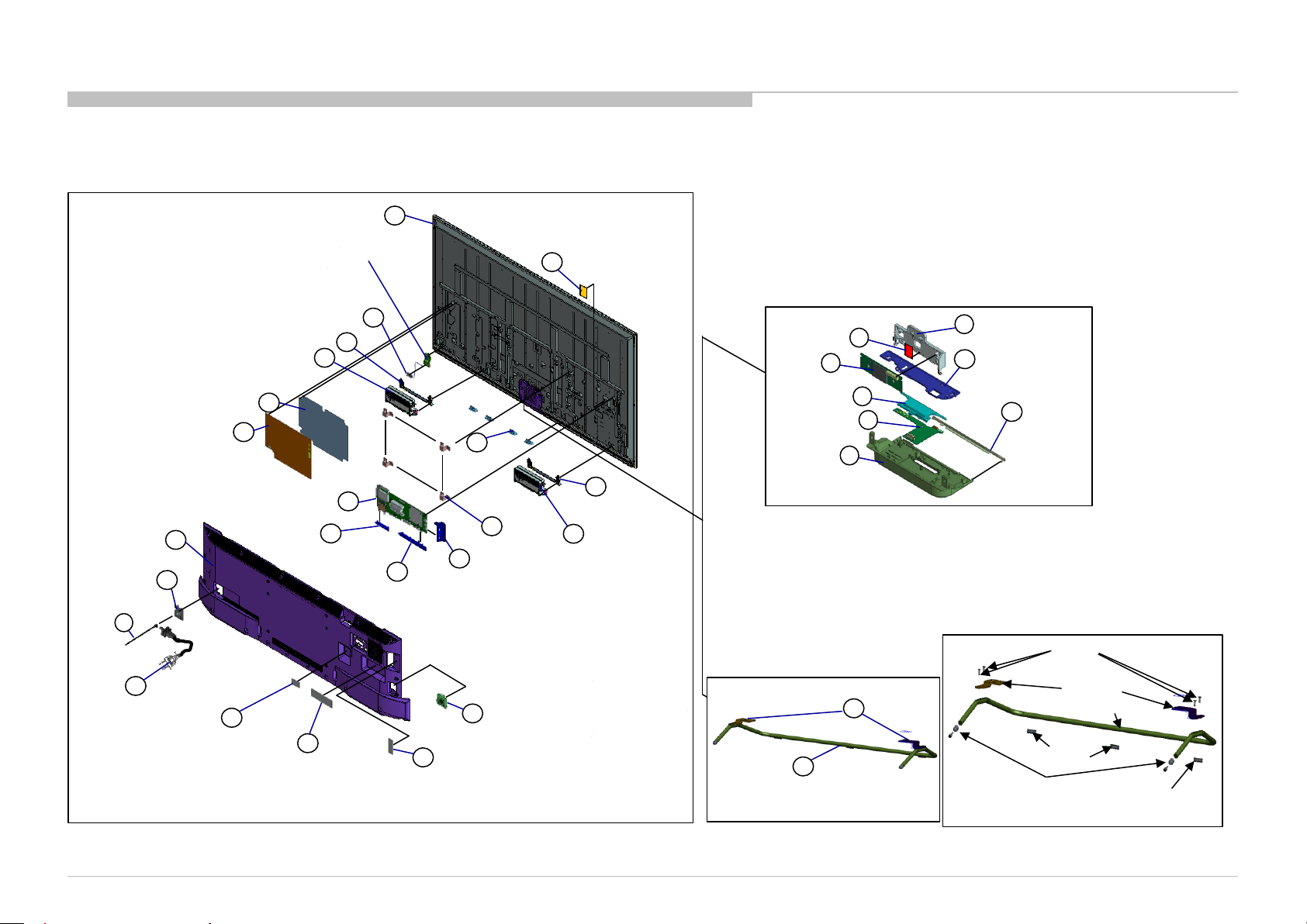
1-1. KDL-65W850C/855C/857C
1-1-1. Disassembly, Exploded View
DISASSEMBLY AND PARTS LIST
UNDERCOVER
AC COVER
CLAMPER,
CABLE
4
This part is not stocked. The purpose of
indicated in this illustrator is just for
reference only.
BRACKET, SP (2L HWK)
SPEAKER BOX ASSY (R)
SHEET, INSULATION
GL1SB BOARD
7
5
17
LCD PANEL
BT ANTENNA
20
9
18
BMX BOARD
BRACKET UNDER, TU
15
11
BRACKET UNDER
22
16
SHEET, THERMAL
SMART CORE BLOCK
14
21
BRACKET,
SC
20
BRACKET, SP
19
BRACET,VESA
12
13
BRACKET SIDE
(2L HWK)
8
SPEAKER BOX
ASSY (L)
SHEET,
THERMAL (SC)
WLAN/BT
MODULE
LIGHT, GUIDE
HSC3_L MOUNT
CASE,
BOTTOM (L)
52
BRACKET, WIFI
53
56
57
58
51
COVER, TOP
54
55
PANEL,
ORNAMENTAL
M4 screw
STAND BLOCK
6
POWER SUPPLY
CORD
LABEL, UNDER
TERMINAL (TU)
1
3
LABEL, UNDER
TERMINAL
KDL-65W850C, 855C, 857C, 75W850C, 855C
LABEL, SIDE
2
TERMINAL
10
SWITCH
UNIT
STAND NECK ASSY
STAND, PIPE
Stand arm
72
71
Rear Foot
Shaft stand
Front foot
Front foot
15
Page 16
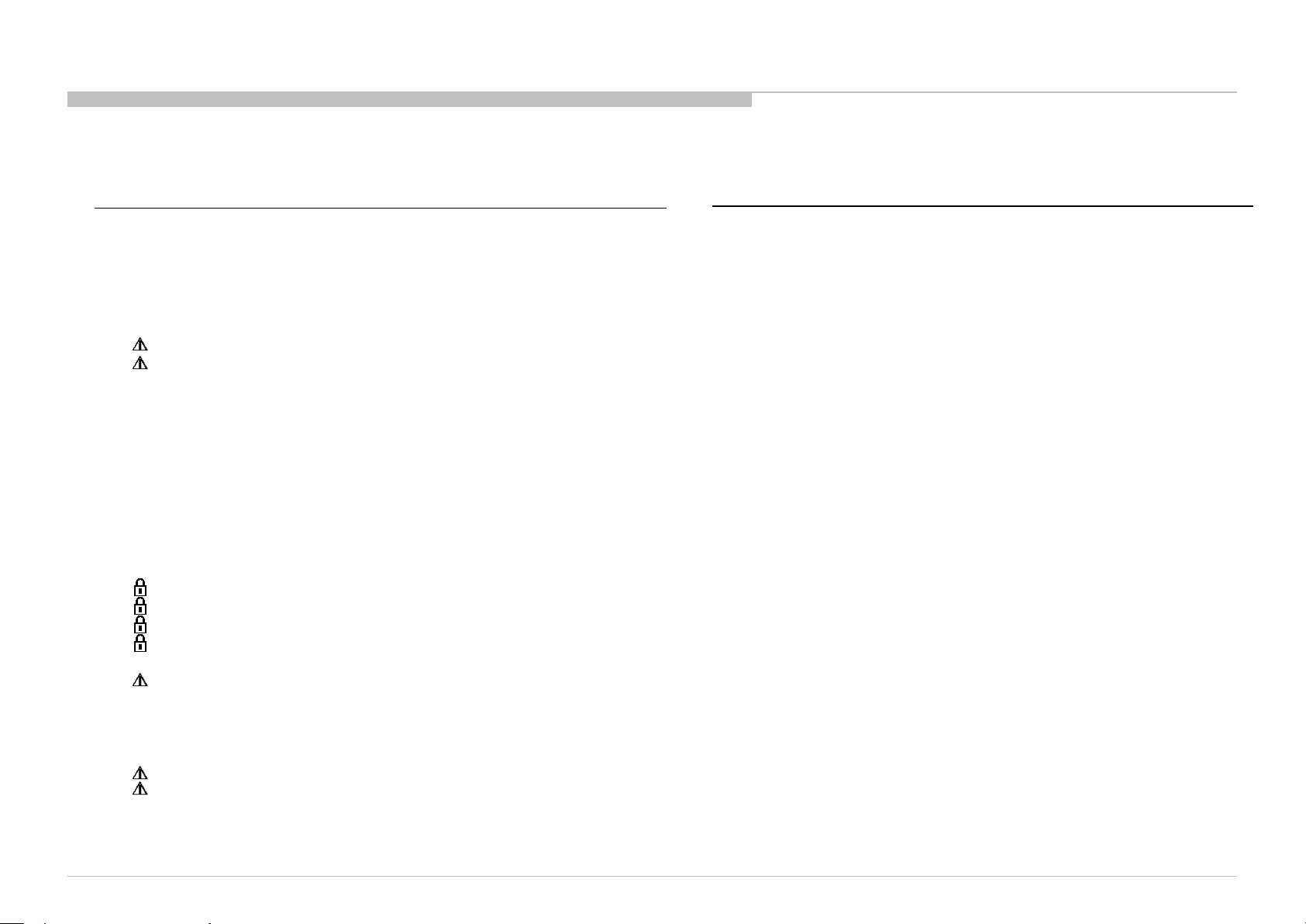
REF. No. PART No. DESCRIPTION MARK
1 4-563-190-11 LABEL, UNDER TERMINAL(TU) CO1/LA8/CR1/ECU
1 4-563-190-21 LABEL, UNDER TERMINAL(TU) UC2
2 4-563-252-01 LABEL, SIDE TERMINAL
3 4-563-273-01 LABEL, UNDER TERMINAL UC2
3 4-563-273-11 LABEL, UNDER TERMINAL CO1/LA8/CR1/ECU
4 4-262-708-04 CLAMPER, CABLE
5 4-299-531-01 AC COVER
6 1-839-691-12 POWER-SUPPLY CORD (WITH CONN.) LA8/CR1/ECU
6 1-839-696-12 POWER-SUPPLY CORD (WITH CONN.) UC2/CO1
7 4-546-827-11 UNDER COVER (2L_EGL) A UC2
7 4-546-827-21 UNDER COVER (2L_EGL) A LA8/CR1/ECU
7 4-546-827-31 UNDER COVER (2L_EGL) A CO1
8 1-859-007-11 SPEAKER BOX ASSY (L)
9 1-859-007-21 SPEAKER BOX ASSY (R)
10 1-798-510-31 SWITCH UNIT (SM-G-WW)
11 4-546-909-12 BRACKET, UNDER TU (MOLD) CO1/LA8/CR1/ECU
11 4-546-909-32 BRACKET, UNDER TU (MOLD) UC2
12 4-545-088-11 BRACKET, UNDER (MOLD)
13 4-545-087-01 BRACKET, SIDE (MOLD)
14 1-754-949-11 BT ANTENNA
15 A-2068-394-A COMPL SVC BMX_XMH_BR GINGA CR1/ECU
15 A-2068-395-A COMPL SVC BMX_XMH_UC UC2
15 A-2068-401-A COMPL SVC BMX_XMH_COL CO1
15 A-2073-259-A COMPL SVC BMX_XMH_BR LA8
16 4-549-186-01 SHEET, THERMAL (BM)
17 1-474-610-11 GL1SB-STATIC CONVERTER (TV)
18 4-549-182-01 SHEET, INSULATION (HWK 2L)
* 19 4-546-473-01 BRACET, VESA (HWK)
20 4-546-824-01 BRACKET, SP (2L HWK) A
21 4-546-470-01 BRACKET, SC (EGL)
22 1-812-090-11 LCD PANEL (A65HVF6S) CO1/LA8/CR1/ECU
22 1-812-091-11 LCD PANEL (A65HVF6B) UC2
1-1. KDL-65W850C/855C/857C
REF. No. PART No. DESCRIPTION MARK
51 4-564-318-01 BRACKET, WIFI
52 1-458-854-11 WLAN/BT MODULE (11N)
53 4-549-528-01 SHEET, THERMAL (SC)
54 4-564-317-01 COVER, TOP
55 4-564-312-01 PANEL, ORNAMENT
56 4-564-313-01 LIGHT, GUIDE
57 A-2066-086-A HSC3_L MOUNT
58 4-564-316-01 CASE, BOTTOM (L)
71 4-546-889-01 STAND,PIPE (2L EGL) A
72 4-546-910-01 STAND NECK ASSY
1-1-1. Disassembly, Exploded View
KDL-65W850C, 855C, 857C, 75W850C, 855C
DISASSEMBLY AND PARTS LIST
16
Page 17
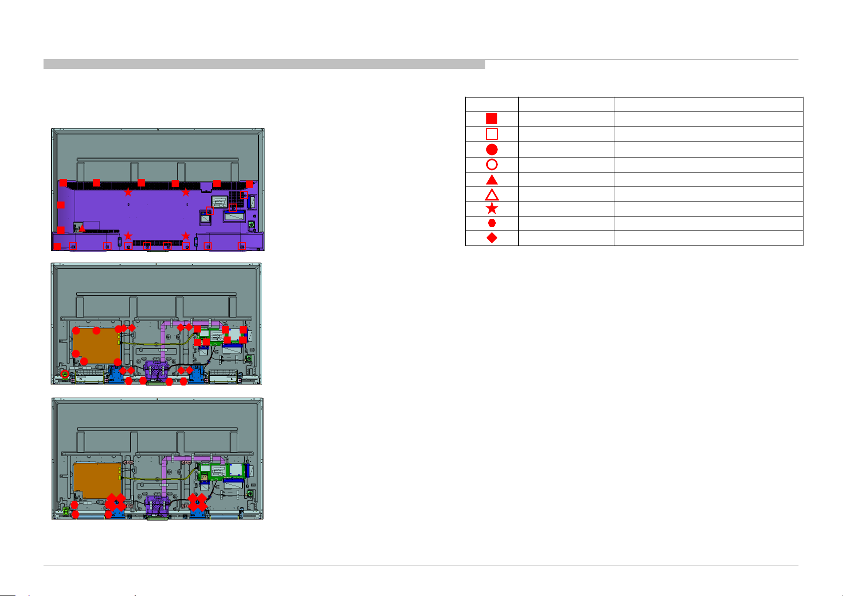
Description
SCREW , +PWH M3X6
SCREW, +BVTP 4X12 TYPE2 IT
SCREW, +PSW M3X6 W12
SCREW (+PSW) (M3X6)
SCREW, +PSW M4X10
SCREW, +PSW M5X20
SCREW, ORNAMENTAL M6X12
SCREW, +PSW M3X8
SCREW, +PSW M4X8
1-1. KDL-65W850C/855C/857C
1-1-2. Screws
Ref Part No
4-452-935-11
2-580-639-01
4-256-393-11
2-990-421-41
4-159-298-01
4-567-082-01
4-268-126-02
2-580-593-01
2-580-600-11
DISASSEMBLY AND PARTS LIST
-3
KDL-65W850C, 855C, 857C, 75W850C, 855C
17
Page 18
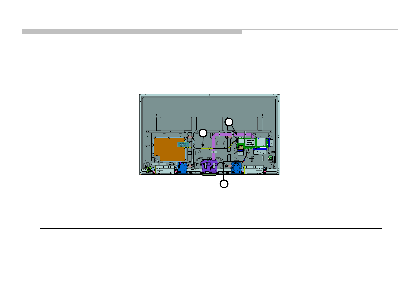
REF. No. PART No. DESCRIPTION MARK
81 1-910-804-95 CONNECTOR ASSY 30P CN9000(BMX)-CN6401(GL1B)(1)
82 1-848-825-11 FLEXIBLE FLAT CABLE 51P CN8400(BMX)-T-CON(1)
83 1-910-804-94 HARNESS ASSY CN1000(BMX)-CN203(SM)-CN101(HSC3-L)- (WIFI/BT) / CN7751(BMX)-SP(1)
1-1. KDL-65W850C/855C/857C
1-1-3. Connectors
DISASSEMBLY AND PARTS LIST
82
81
83
KDL-65W850C, 855C, 857C, 75W850C, 855C
18
Page 19
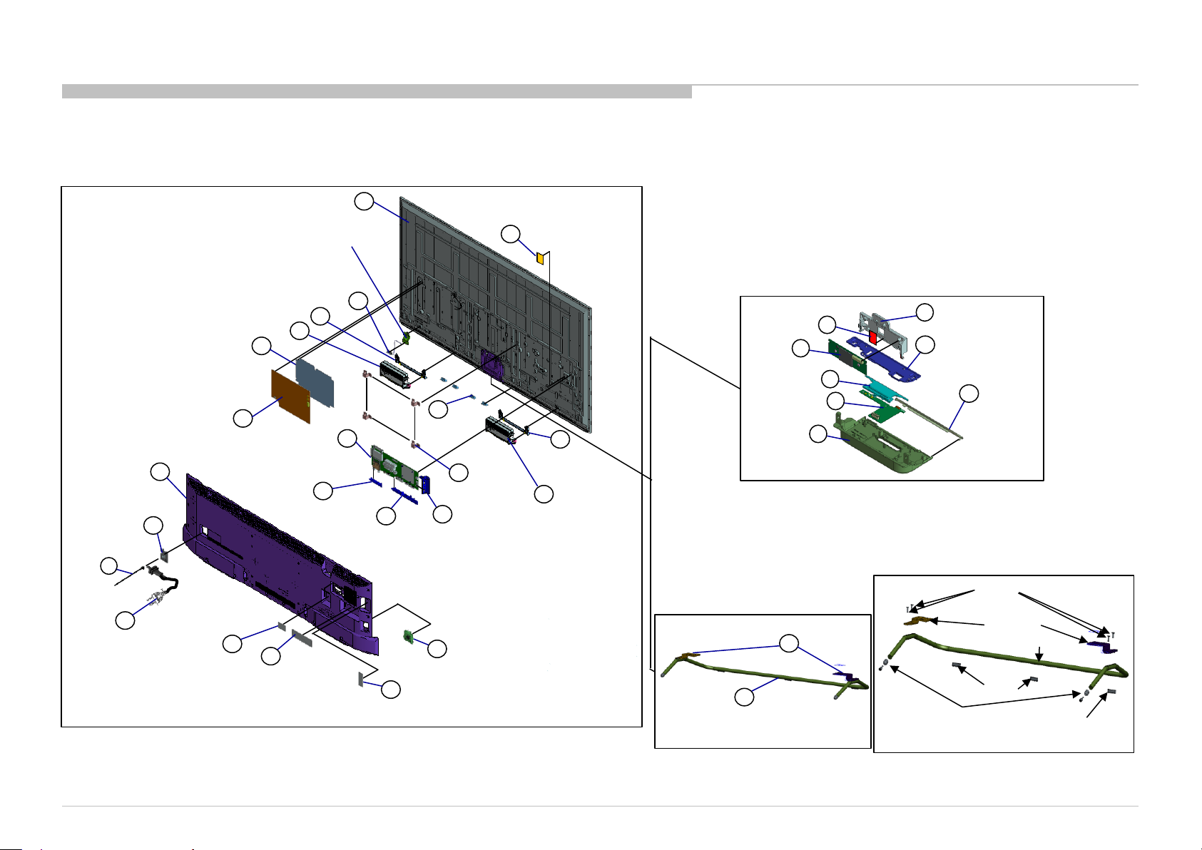
1-2. KDL-75W850C/855C
1-2-1. Disassembly, Exploded View
DISASSEMBLY AND PARTS LIST
UNDERCOVER
AC COVER
CLAMPER,
CABLE
4
6
POWER SUPPLY
CORD
This part is not stocked. The purpose of
indicated in this illustrator is just for
reference only.
BRACKET, SP (2L HWK)
SPEAKER BOX ASSY (R)
SHEET, INSULATION
GL1C BOARD
7
5
1
LABEL, UNDER
TERMINAL (TU)
LCD PANEL
9
18
17
BMX BOARD
BRACKET
UNDER, TU
3
LABEL, UNDER
TERMINAL
BT ANTENNA
14
20
15
11
BRACKET UNDER
22
21
BRACKET,
SC
19
BRACKET,VESA
12
2
LABEL, SIDE TERMINAL
13
BRACKET
SIDE
SWITCH
10
UNIT
16
SHEET, THERMAL
20
BRACKET, SP
(2L HWK)
8
SPEAKER BOX
ASSY (L)
STAND BLOCK
STAND NECK ASSY
71
STAND, PIPE
SHEET,
THERMAL (SC)
WLAN/BT
MODULE
LIGHT, GUIDE
HSC3_L MOUNT
CASE,
BOTTOM (L)
52
72
SMART CORE BLOCK
53
56
57
58
51
BRACKET, WIFI
COVER, TOP
54
55
Rear Foot
PANEL,
ORNAMENTAL
M4 screw
Stand arm
Shaft stand
Front foot
Front foot
KDL-65W850C, 855C, 857C, 75W850C, 855C
19
Page 20
REF. No. PART No. DESCRIPTION MARK
1 4-563-190-21 LABEL, UNDER TERMINAL (TU) UC2
1 4-563-190-11 LABEL, UNDER TERMINAL (TU) BR6
2 4-563-252-01 LABEL, SIDE TERMINAL
3 4-563-273-01 LABEL, UNDER TERMINAL UC2
3 4-563-273-11 LABEL, UNDER TERMINAL BR6
4 4-262-708-04 CLAMPER, CABLE
5 4-299-531-01 AC COVER UC2
5 4-297-989-01 AC COVER BR6
6 1-846-001-11 POWER SUPPLY CORD (WITH CONN)
7 4-546-828-11 UNDER COVER (3L_EGL) A UC2
7 A-2068-963-A UNDER COVER (3L_EGL) A BR6
8 1-859-007-11 SPEAKER BOX ASSY (L)
9 1-859-007-21 SPEAKER BOX ASSY (R)
10 1-798-510-41 SWITCH UNIT (SM-G-KIT) BR6
10 1-798-510-31 SWITCH UNIT (SM-G-WW) UC2
11 4-546-909-32 BRACKET, UNDER TU (MOLD) UC2
11 4-546-909-42 BRACKET, UNDER TU (MOLD) BR6
12 4-545-088-11 BRACKET, UNDER (MOLD) UC2
12 4-545-088-41 BRACKET, UNDER (MOLD) BR6
13 4-545-087-01 BRACKET, SIDE (MOLD) UC2
13 4-545-087-11 BRACKET, SIDE (MOLD) BR6
14 1-754-949-11 BT ANTENNA
15 A-2068-394-A COMPL SVC BMX_XMH_BR GINGA BR6
15 A-2068-395-A COMPL SVC BMX_XMH_UC UC2
16 4-570-777-01 SHEET, THERMAL (BM17)
17 1-474-609-11 GL1C-STATIC CONVERTER(TV)
18 4-549-400-01 SHEET, INSULATION (EGL 3L)
* 19 4-546-473-01 BRACET,VESA (HWK)
20 4-546-824-01 BRACKET, SP (2L HWK) A UC2
21 4-546-470-01 BRACKET, SC (EGL)
22 1-812-093-11 LCD PANEL (B75HF59B) UC2
22
1-812-092-11
LCD PANEL (B75HF59S) BR6
1-2. KDL-75W850C/855C
REF. No. PART No. DESCRIPTION MARK
51 4-547-397-01 BRACKET, WIFI BR6
51 4-564-318-01 BRACKET, WIFI UC2
52 1-458-854-11 WLAN/BT MODULE(11N)
53 4-549-528-01 SHEET, THERMAL (SC)
54 4-547-395-01 COVER, TOP BR6
54 4-564-317-01 COVER, TOP UC2
55 4-564-312-01 PANEL, ORNAMENT UC2
55 4-547-389-01 PANEL, ORNAMENT BR6
56 4-564-313-01 LIGHT, GUIDE UC2
56 4-547-390-01 LIGHT, GUIDE BR6
57 A-2066-086-A HSC3_L MOUNT
58 4-547-393-01 CASE, BOTTOM (L) BR6
58 4-564-316-01 CASE, BOTTOM (L) UC2
71 4-546-894-01 STAND,PIPE (3L EGL) A UC2
71 A-2068-965-A STAND,PIPE (3L EGL) A BR6
72 4-546-910-01 STAND NECK ASSY UC2
72 A-2069-466-A STAND NECK ASSY BR6
1-2-1. Disassembly, Exploded View
KDL-65W850C, 855C, 857C, 75W850C, 855C
DISASSEMBLY AND PARTS LIST
20
Page 21
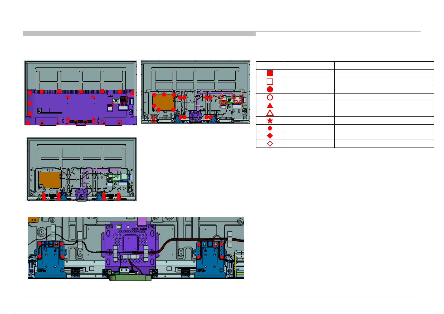
Description
SCREW , +PWH M3X6
SCREW, +BVTP 4X12 TYPE2 IT
SCREW, +PSW M3X6 W12
SCREW (+PSW) (M3X6)
SCREW, +PSW M4X10
SCREW, +PSW M5X20
SCREW, ORNAMENTAL M6X12
SCREW, +PSW M3X8
SCREW, +PSW M4X8
PULLEY, STAND (HWI)
1-2. KDL-75W850C/855C
1-2-2. Screws
DISASSEMBLY AND PARTS LIST
Ref Part No
4-452-935-11
2-580-639-01
4-256-393-11
2-990-421-41
4-159-298-01
4-567-082-01
4-268-126-02
2-580-593-01
2-580-600-11
4-534-964-01
-3
KDL-65W850C, 855C, 857C, 75W850C, 855C
21
Page 22
REF. No. PART No. DESCRIPTION MARK
81 1-910-804-96 HARNESS ASSY CN1000(BMX)-CN203(SM)-CN101(HSC3-L)- (WIFI/BT) / CN7751(BMX)-SP(1)
82 1-910-804-97 CONNECTOR ASSY 30P CN9000(BMX)-CN6401(GL1B)(1)
83 1-848-826-11 FLEXIBLE FLAT CABLE 51P(UC2) CN8400(BMX)-T-CON(1)
83 1-848-823-11 FLEXIBLE FLAT CABLE 51P(BR6) CN8400(BMX)-T-CON(1)
1-2. KDL-75W850C/855C
1-2-3. Connectors
DISASSEMBLY AND PARTS LIST
82
83
81
KDL-65W850C, 855C, 857C, 75W850C, 855C
22
Page 23
PART No. DESCRIPTION MARK PART No. DESCRIPTION MARK
2-650-770-21 SLIDE, CLAMP 1-492-975-21 REMOTE COMMANDER (RMT-TX100B) CO1/LA8/CR1/ECU
* 4-534-964-01 PULLEY, STAND (HWI) 1-492-975-31 REMOTE COMMANDER (RMT-TX100B) BR6
7-600-031-97 TAPE (3M 1350FB-1)15MMX66M BLK 1-492-978-21 REMOTE COMMANDER (RMT-TX100U) UC2
1-785-504-21
ADAPTOR, CONVERSION LA8/CR1/ECU
1-839-691-12 POWER-SUPPLY CORD (WITH CONN.) LA8/CR1/ECU
1-839-696-12 POWER-SUPPLY CORD (WITH CONN.) UC2/CO1
1-845-283-14 IR BLASTER UC2
* 1-848-803-11 RCA CONVERSION CABLE BR6/CO1/LA8/
CR1/ECU
*
4-562-056-11 REFERENCE GUIDE UC2
* 4-562-057-31
REFERENCE GUIDE CR1/ECU
* 4-562-058-31 REFERENCE GUIDE CO1/LA8
*
4-562-059-11 REFERENCE GUIDE BR6
*
4-567-082-01 SCREW, +PSW M5X20 (For STAND)
*
4-567-081-01 SCREW, +PSW M6X12 (For STAND)
7-600-031-96 TAPE (3M 1350FW-1)15MMX66M WHT
DISASSEMBLY AND PARTS LIST
1-3. KDL-65W850C/855C/857C,75W850C/855C
1-3-1. MISCELLANEOUS 1-3-2. ACCESSORIES
KDL-65W850C, 855C, 857C, 75W850C, 855C
23
Page 24
SEC 2. ADJUSTMENT
>>
>>
>>
>>
>>
>>
>>
[</>] Set [Home]Exit
General Setting
Tuner
Wifi
Service Mode
Model
Self diagnosis History
Video / Audio
Panel / PQ
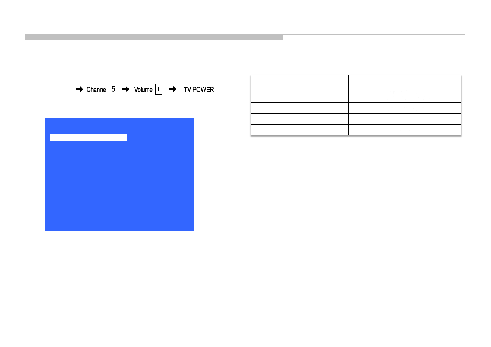
ACCESSING SERVICE MODE
1) Turn on the main power switch to place this set in standby mode.
2) Press the buttons on the remote commander as follows, and entering service
mode.
i+ (info)
3) Service mode display.
4) How to use the remote commander.
Function The flow of control
Service mode on
Service mode off <MENU>/<HOME>
Item up / down <↑>/ <↓>
Execute <OK>
<Display><5><Vol Up><Power>
<Test>+<TV>/
5) After entering service mode, then turn off the power switch.
KDL-65W850C, 855C, 857C, 75W850C, 855C
24
Page 25
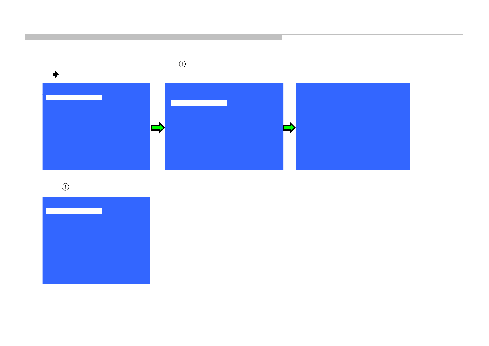
ACCESSING SOFTWARE VERSION
>>
>>
>>
>>
>>
>>
>>
[</>] Set [Home]Exit
General Setting
Tuner
Wifi
Service Mode
Model
Self diagnosis History
Video / Audio
Panel / PQ
>>
Model Information
>>
Model Number Setting
>>
SERIAL NUMBER EDIT
[</>] Set [Home]Exit
Model
Status Inf ormation
Main Micro
TM1.000
TD1.000
TB1.000
PQ1.000
AQ0.00X
<Ext>
89.AB.CD.EF
0x054C
0x0A92
0x2207
CameraVID:
CameraPIC:
CameraFW:
SW Version:
NVM Version:
Boot Version:
PQ Version:
AQ Version:
exFRC:
>>
>>
>>
>>
>>
>>
>>
[</>] Set [Home]Exit
General Setting
Tuner
Wifi
Service Mode
Model
Self diagnosis History
Video / Audio
Panel / PQ
1) In Service Mode, select “Model Information “ Press (Enter)
or button on Remote to enter status information.
2) Press (Enter) or “Return” button on Remote to back to Service Mode.
ADJUSTMENT
KDL-65W850C, 855C, 857C, 75W850C, 855C
25
Page 26
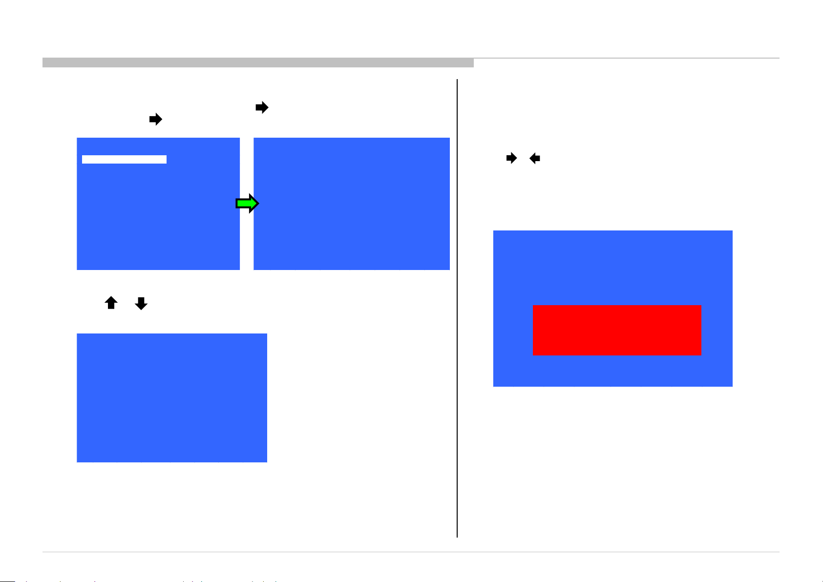
ACCESSING SERIAL NUMBER EDIT
<[ ]>
Model Number Setting
KDL-40X500B
Serial Numbe r Edit
_ _ _ _ _ _ _
Service Mode
Status Information
>>
Model Information
>>
>>
>>
>>
>>
>>
>>
>>
[</>] Set [Home]Exit
General Setting
Tuner
Wifi
Service Mode
Model
Self diagnosis History
Video / Audio
Panel / PQ
<[ ]>
Model Number Setting
KDL-40X500B
Serial Numbe r Edit
_ _ _ _ _ _ _
Service Mode
Status Information
>>
Model Information
>>
<[ ]>
Model Number Setting
KDL-40X500B
Serial Numbe r Edit
9 9 9 9 9 9 9
Service Mode
Status Information
>>
Model Information
>>
Yes No
Input Data correct?
1) In Service Mode, select “Model” pressing button. Select “Serial Number
Edit” pressing button.
2) Press or button to select number.
* The font color of “Yes” is change to black when it is selected.
ADJUSTMENT
3) Serial Number can be set ONLY ONCE.
After user input data , press <Enter>.
Pop dialog will appear to inform user to confirm data.
Press or button to select “Yes” or “No” .
Select “Yes” if input data is correct.
Select “No” if input data is incorrect.
Press <Enter> to save answer.
KDL-65W850C, 855C, 857C, 75W850C, 855C
Note: * The font color of “Yes” is change to black when it is selected.
26 26
Page 27
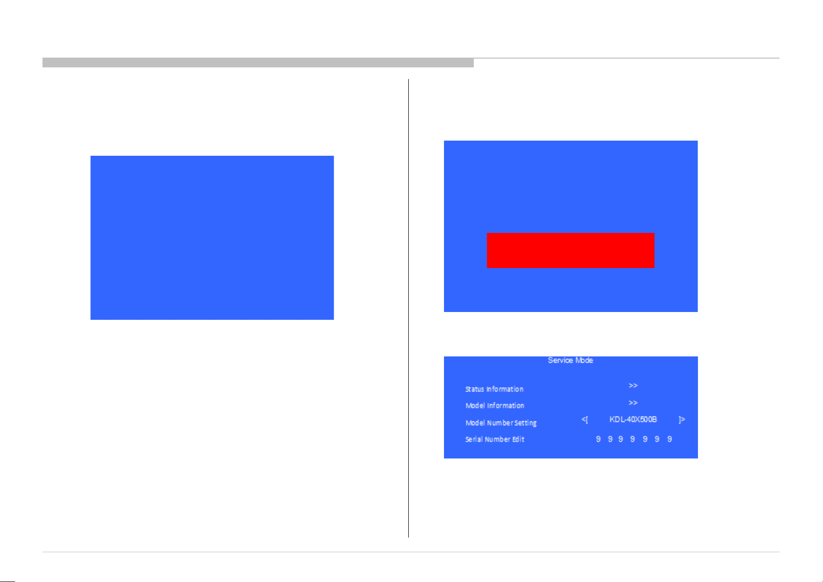
ADJUSTMENT
<[ ]>
Model Number Setting
KDL-40X500B
Serial Numbe r Edit
9 9 9 9 9 9 9
Service Mode
Status Information
>>
Model Information
>>
<[ ]>
Model Number Setting
KDL-40X500B
Serial Number Edit
9 9 9 9 9 9 9
Service Mode
Status Information
>>
Model Information
>>
Yes No
Input Data correct?
4) If “Yes” is selected, the input data is saved into EEPROM.
“Serial Number Edit” is grayed out and the serial number that
has been input is displayed.
User will not able to edit anymore.
Note: * The font color of “Serial Number Edit” is change to orange after
“Yes” is selected.
5) If “No” is selected, the input data is not saved into EEPROM.
The serial number that has been input is displayed.
User can still edit the Serial Number.
Note: * The font color of “No” is change to black when it is selected.
KDL-65W850C, 855C, 857C, 75W850C, 855C
Note: * The font color of “Serial Number Edit” is white after “No” is selected.
27 27
Page 28
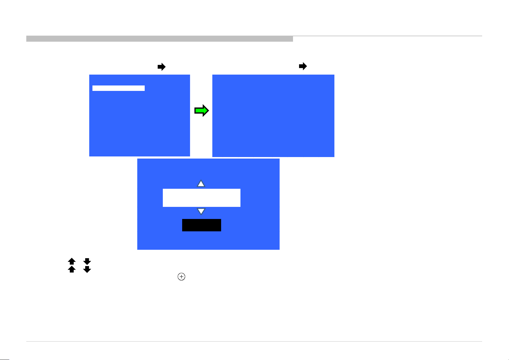
ACCESSING MODEL NUMBER SETTING
>>
>>
>>
>>
>>
>>
>>
[</>] Set [Home]Exit
General Setting
Tuner
Wifi
Service Mode
Model
Self diagnosis History
Video / Audio
Panel / PQ
<[ ]>
Model Number Setting
KDL-40X500B
Serial Numbe r Edit
_ _ _ _ _ _ _
Service Mode
Status Information
>>
Model Information
>>
_ _ _ _ _ _ _ _ _ _ _ _
OK
[MODEL_NUMBER_SETTING]
1) In Service Mode, select “Model” pressing button. Select “Model Number Setting” pressing button.
ADJUSTMENT
2) Press or button on Remote to input numbers.
3) Press or arrow key to Product Name Candidate. (e.g. KDL-40X500B CO1, KDL-40X500C BR6)
4) Select one Product Name from the LIST, press (Enter) will pop dialog to inform user to confirm data.
5) Press “OK” button to select YES or No.
Select OK if input data is correct.
Select NO if input data is incorrect.
Press <Enter> to save answer.
Model dependent settings will be overwritten into EEPROM.
KDL-65W850C, 855C, 857C, 75W850C, 855C
28
Page 29
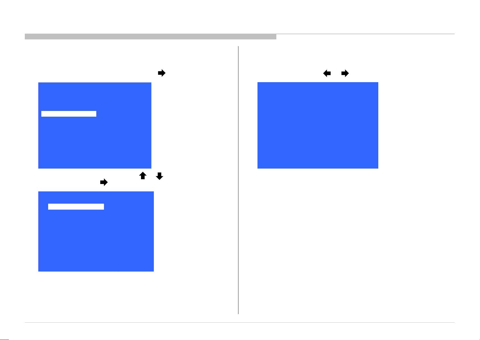
W/B ADJUSTMENT VIA SERVICE MODE
[</>] Set [Home]Exit
Panel / PQ
Back
<<
WB Adjus tment
>>
WB/Mura /CUC data trans fer
>>
Back
R WB Gai n
<[ 0 ]>
G WB Gai n
<[ 0 ]>
B WB Gai n
<[ 0 ]>
R WB Offs et
<[ 0 ]>
G WB Offs et
<[ 0 ]>
B WB Offs et
<[ 0 ]>
<<
[</>] Set [Home]Exit
>>
>>
>>
>>
>>
>>
>>
Service Mode
[</>] Set [Home]Exit
Tuner
Wifi / BT
Model Information
Self diagnosis History
Video / Audio
Panel / PQ
General Setting
Apply when B* board or Panel is replaced.
ADJUSTMENT
1) In Service Mode, select “Panel/PQ” pressing button.
2) Go to “WB Adjustment”, category by or button. To select
“WB Adjustment”, press button.
3) To change data, press or button.
KDL-65W850C, 855C, 857C, 75W850C, 855C
29
Page 30
ADJUSTMENT
[</>] Set [Home]Exit
Panel / PQ
Back
<<
WB Adjus tment
>>
WB/Mura /CUC data trans fer
>>
>>
>>
>>
>>
>>
>>
>>
Service Mode
[</>] Set [Home]Exit
Tuner
Wifi / BT
Model Information
Self diagnosis History
Video / Audio
Panel / PQ
General Setting
Back
<<
<[ 0. SoC to T-con ]>
Mura data tra nsfer
<[ 0. SoC to T-con ]>
CUC data tra nsfer
<[ 0. SoC to T-con ]>
[Start]
[</>] Set [Home]Exit
WB/Gamma da ta trans fer
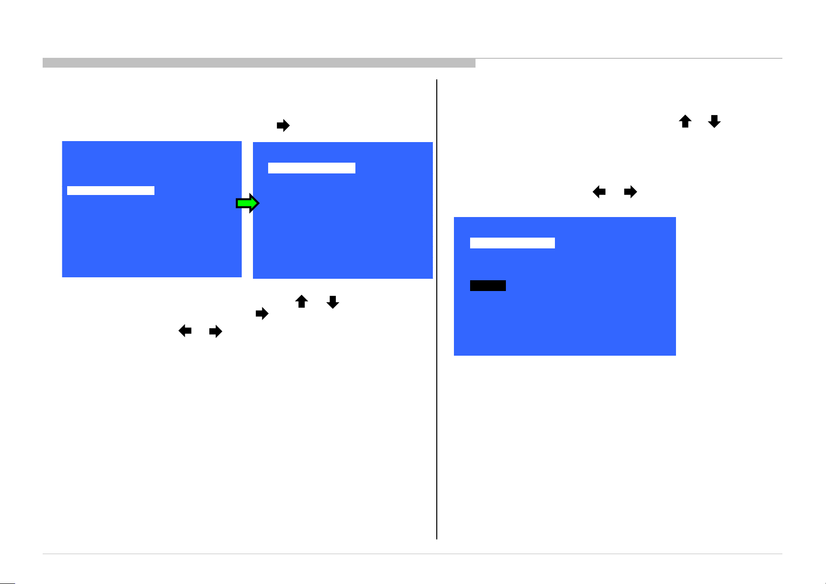
WB/MURA/CUC DATA TRANSFER VIA SERVICE MODE
Apply when B* board or Panel is replaced.
1) In “Service Mode, select “Panel/PQ” pressing button.
2) Go to “WB/Mura/CUC data transfer”, category by or button. To
select “WB/Mura/CUC data transfer”, press button.
3) To change data, press or button.
4) In “WB/Mura/CUC data transfer:
a) Select “WB/Gamma data transfer” by pressing or on remote
commander until cursor is on “WB/Gamma data transfer”.
Selectable items are:
→ 0. SoC to T-con
→ T-con to SoC
→ Initialize data
b) To change the items, press or on remote commander.
c) Select “[Start]” and press “Enter” button to start transfer.
KDL-65W850C, 855C, 857C, 75W850C, 855C
30
Page 31
SEC 3. TROUBLE SHOOTING
No Power Remote Network Audio Skype
Smart
Core
Bluetooth
(BT)
2 3 4 5 6 7 8 9 10
No White
Pow er LED
& does not
response to
remote
(Dead Set)
Stationary
coloured
lines or
dots
No video
One of
Inputs
No video
all Inputs
No Remote
Wireless
can't
connect
No Audio
Skype
Can't Work
Smart Core
no LED
(Set is still
alive)
Bluetooth /
One Step
Remote
(OSR) can't
connect
BAX Board p l p p l l p p l l p p l p p p
G* Board l p p l l p
H* Board l l l
Speaker p l
Wifi & BT
Module
l l p l
LD Board l p
LVDS FFC p p p p
Tcon p l p p p p
LCD Panel l l l p l p
Power Power LD
Panel
(Tcon)
Panel
(Backlight)
TEMP
Software
Emitter
Audio
FAN
(N/A)
Local
I2C
Video - missing or distorted
Reference
Symptoms - Shutdown. Power LED
blinking red diagnostics sequences
Problem
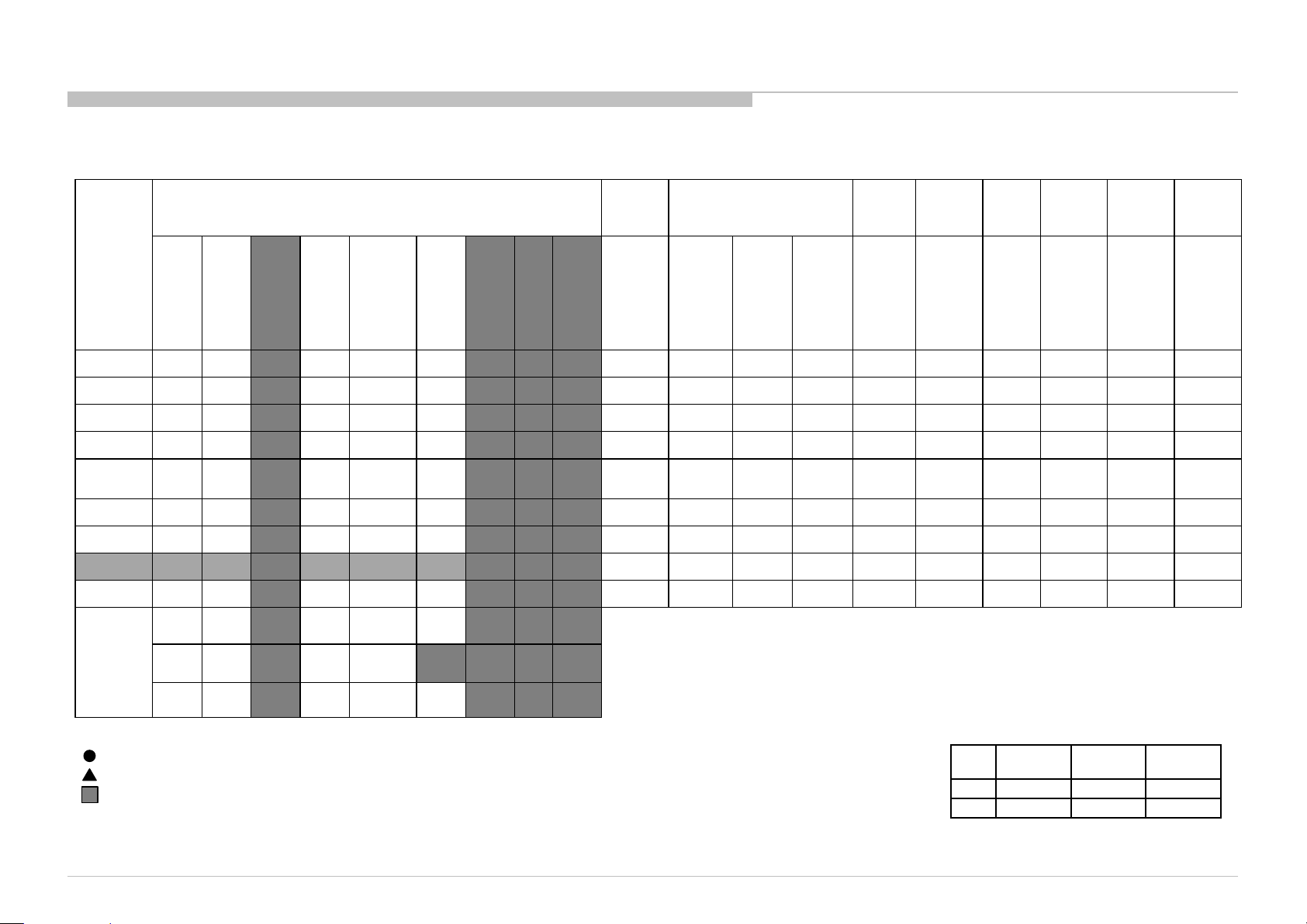
3-1. TRIAGE CHART
Most likely defective part
Secondary possible defective part
Not Applicable
Size B* Board G* Board H* Board
65” BMX GL1SB HSC3
75” BMX GL1C HSC3
KDL-65W850C, 855C, 857C, 75W850C, 855C
31
Page 32
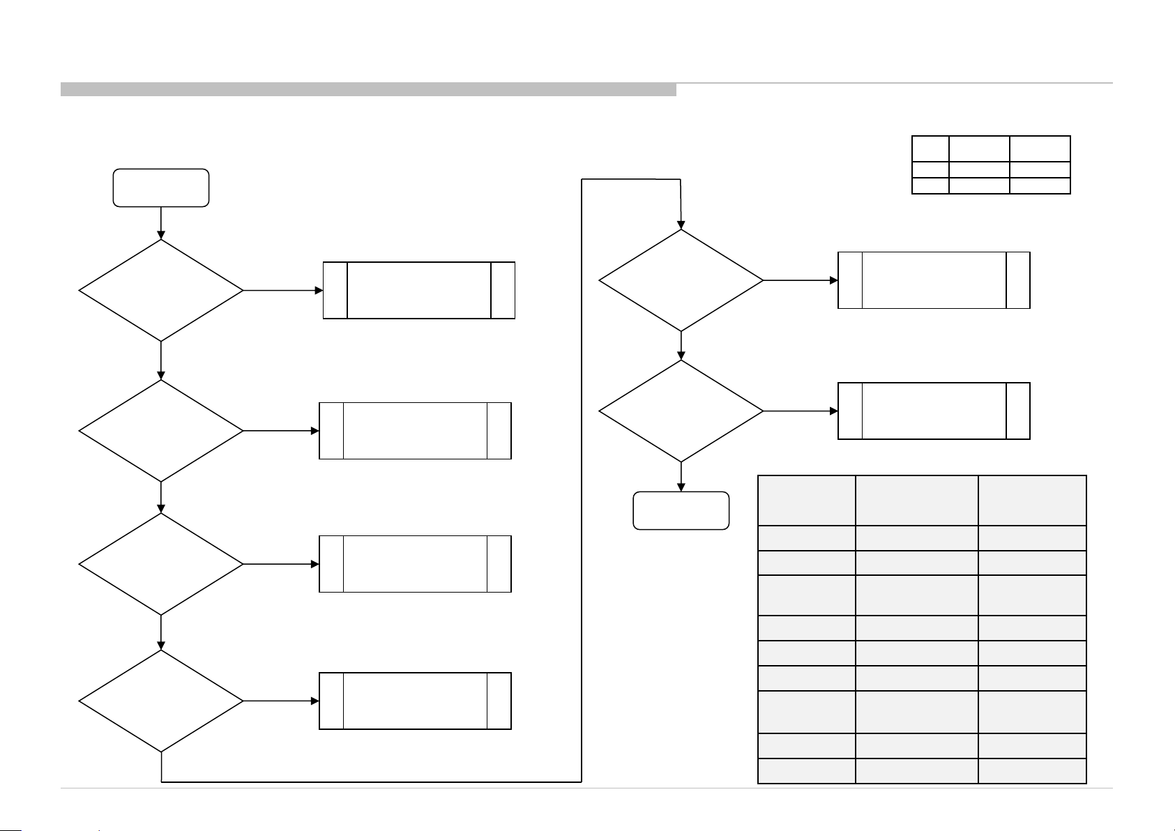
3-2. NO POWER
Size
B* Board
G* Board
3-2-1. NO Power (XMH-65)
TROUBLE SHOOTING
NO POWER
Check Fuse F6101
& FB801S , for open
No
Check Stby
3.3V at Pin 5 of
Connector CN6401
Yes
Check Power ON
at Pin 9
Of connector CN6401
Yes
Yes
No Voltage
No Voltage
Replace PSU
Replace PSU
Main Board Problem
(B*)
Check BL_ON
at Pin 3 of
Connector
CN6401
Yes
Check +Out1
and +Out2 at
CN5801
Yes
PSU OK
No Voltage
65”
75”
Main Board Problem
BMX GL1SB
BMX GL1C
(B*)
No Voltage
Replace PSU
Output
Name
BL_ON 2.64V~3.3V Pin 3
STBY3.3V 3.35V~3.55V Pin 5
AC OFF
DET
BL_ERR 0V Pin 8
Output Voltage
3.45V Pin 7
Connector
CN6401
Check Reg12V at
Pin 13Pin 18 of
Connector CN6401
No Voltage
Yes
KDL-65W850C, 855C, 857C, 75W850C, 855C
Replace PSU
Power_ON 2.64V~3.3V Pin 9
REG12V 12.2V~13.2V Pin 13Pin 18
Output
Name
+OUT1 173.6V~250.3V Pin 1
+OUT2 173.6V~250.3V Pin 2
Output Voltage
Connector
CN5801
32
Page 33
TROUBLE SHOOTING
Size
B* Board
G* Board
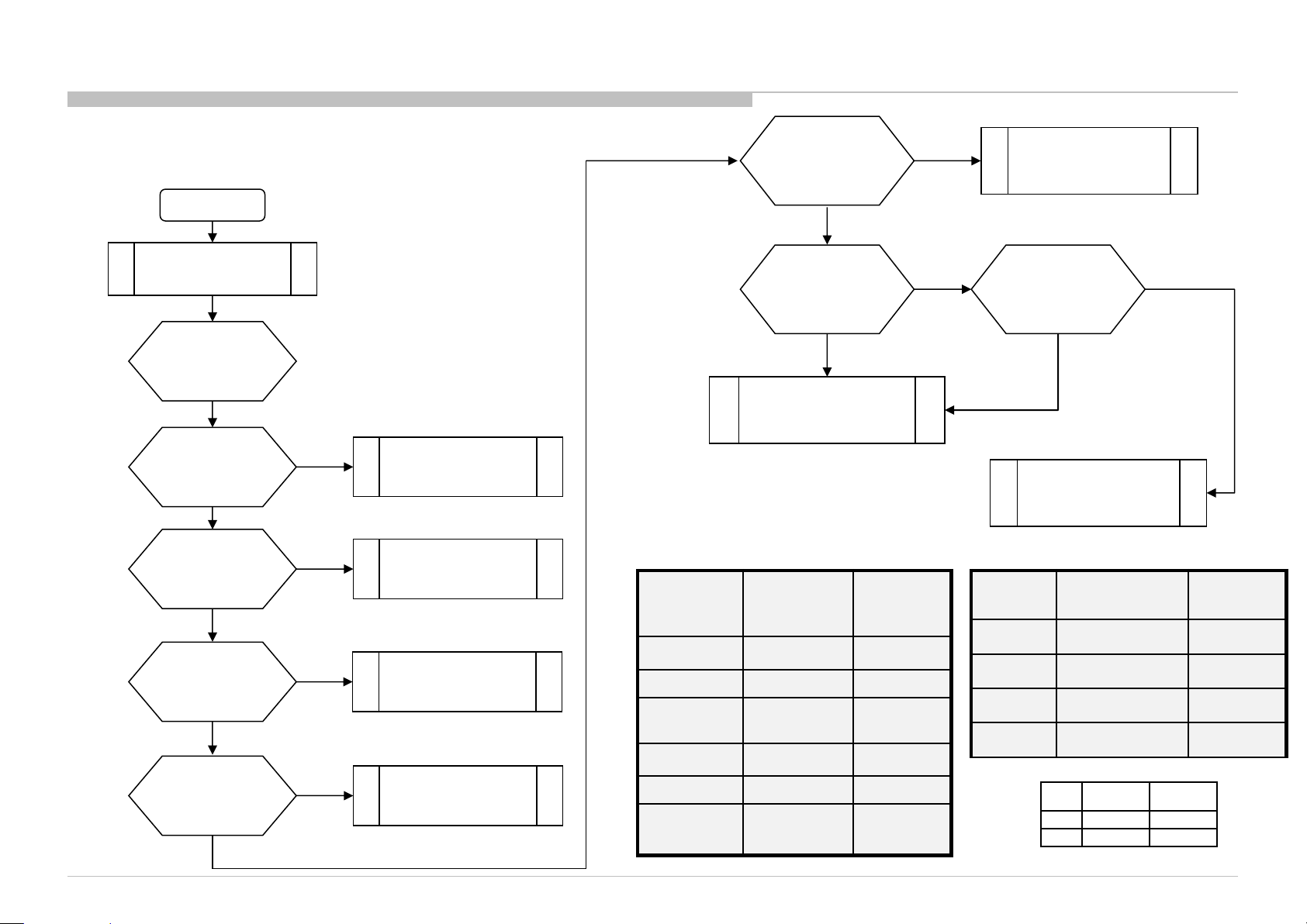
3-2-2. NO Power (XMH-75)
START
AC Connect
(80 ~ 288V
Can TV power on?
No
F6101 Fuse
OPEN check
No
STBY output check
(3.35~3.55V)
Yes
Power
ON input check
(~3.3V)
Yes
12V output check
(12.2~13.2V)
Yes
KDL-65W850C, 855C, 857C, 75W850C, 855C
Yes
No
No
No
Replace
Power supply
(G*)
Replace
Power supply
(G*)
Main Board
Problem(B*)
Replace
Power supply
(G*)
BL_ON active HIGH
(~3.3V)
Yes
LED output check
(133.4V~192.9V)
Yes
Power Supply
Working Normal
Output
Name
BL_ON 2.64V~3.3V Pin 3
STBY3.3V 3.35V~3.55V Pin 5
AC OFF
DET
BL_ERR 0V Pin 8
Power_ON 2.64V~3.3V Pin 9
REG12V 12.2V~13.2V
Output
Voltage
3.45V Pin 7
Connector
CN6401
Pin 13Pin
18
No
Case 4
no
Main Board
Problem (B*)
Yes
BL Err level check
(~2.8V)
No
Replace Power supply
(G*)
Output
Name
+OUT1 133.4V ~ 192.9V Pin 1
+OUT2 133.4V ~ 192.9V Pin 2
+OUT3 133.4V ~ 192.9V Pin 3
+OUT4 133.4V ~ 192.9V Pin 4
Output Voltage
65”
75”
BMX GL1SB
BMX GL1C
Connector
CN5801
33
Page 34
3-2-3. NO Power (DC/DC Converter Check)
Size
B* Board
G* Board
START
TROUBLE SHOOTING
Check C9216 Voltage.
Is the voltage 3.3V?
Yes
Check C9224 Voltage.
Is the voltage 1.5V?
Yes
Check C9188 Voltage.
Is the voltage 5V?
Yes
Check C9203 Voltage.
Is the voltage 1V?
No
No
No
No
3.3V DDCON check.
(Change B* Board)
1.5V DDCON check.
(Change B* Board)
5.0V DDCON check.
(Change B* Board)
1.0V DDCON check
(Change B* Board)
Check C9207 is
it 1.05V?
Yes
Check C9230 is
it 1.8V?
Yes
Check 3.3V_MAIN
C9005 Voltage.
Is the voltage 3.3V?
Yes
END
DDCON/LDO working normal
No
No
No
1.05V LDO check
(Change B* Board)
1.8V DDCON check
(Change B* Board)
3.3V_MAIN check
(Change B* Board)
Yes
KDL-65W850C, 855C, 857C, 75W850C, 855C
65”
75”
BMX GL1SB
BMX GL1C
34
Page 35
3-2-4. NO Power (Muffin Replacement (Main Device))
Muffin
replacement flow
TROUBLE SHOOTING
eMMC erase
Muffin replacement
Product SW write
Recover?
Yes
Muffin issue
Data on eMMC need
to be erase first
before changing
Muffin
No
Board Issue
KDL-65W850C, 855C, 857C, 75W850C, 855C
35
Page 36
3-3. LED BLINKING
Size
B* Board
G* Board
1) 2 times blinking (Main Power Error)
BMX board (XM-H) only → G* Board
2-time blinking
TROUBLE SHOOTING
Check +19.5V_SS
at pin 15/17 of CN9000
or JL9011
on B* Board,
Voltage > 13.2V ?
No
B* Board
KDL-65W850C, 855C, 857C, 75W850C, 855C
Yes
G* Board
65”
75”
BMX GL1SB
BMX GL1C
36
Page 37
2) 3 times blinking (DC Alert & Communication Error)
Size
B* Board
G* Board
3-time blinking
DC_ALERT
Check +5.0V_MAIN
at L9015, 4.959V
<Voltage<5.285V?
NG
F9013, IC9021,
etc (B* Board)
Check
Speaker Impedance
at SP Connector,
8Ω±1.2Ω ?
OK
TROUBLE SHOOTING
AUDIO
NG
Speaker
OK
Check I2C_A
/ I2C_D bus:
Probe JL6010, JL6011
/ JL6021/JL6022
OK
KDL-65W850C, 855C, 857C, 75W850C, 855C
NG
TUNER
I2C bus dumping
or Muffin
Check Audio
+12.5V
at pin 16/18 of CN9000
on the B* Board
OK
Check
+12.5V
at Power Amp side
of F7751 on
the B* Board
OK
IC7751, etc
(B* Board)
NG
NG
G* Board
F7751, IC7751
, etc (B* Board)
65”
75”
BMX GL1SB
BMX GL1C
37
Page 38
3) 5 times blinking (Panel Communication Error (12.5V NG))
Size
B* Board
G* Board
5-times blinking
TROUBLE SHOOTING
Check
PANEL_VCC 12.5V at
CN8400
on the B* Board
OK
Replace the Harness
Between G* /LD board
and B board
NG
Replace
the LVDS Harness
NG
Symptom
improve
Symptom
improve
G* Board/LD
LVDS Harness
Harness
Change
B* Board
Symptom
improvement
B*Board
Refer I2C Error
Checking in next slide
NG
Change
Panel (T-con)
NG
KDL-65W850C, 855C, 857C, 75W850C, 855C
65”
75”
BMX GL1SB
BMX GL1C
38
Page 39
4) 5 times blinking (Panel Communication Error (I2C Error))
Size
B* Board
G* Board
TROUBLE SHOOTING
5-times blinking
PANEL ID Check
Check I2C (Data & CLK)
At CL
NG NG NG
XM-H/A/DT (BMX): CL8411 &
CL8412
OK OK
INIT_DONE
Check I2C (Data & CLK)
At CL
I2C Error
Change B* Board
NG
Change FFC FFC NG
I2C Communication
Check I2C (Data & CLK)
At CL
B* Board NG
OK
OK
KDL-65W850C, 855C, 857C, 75W850C, 855C
NG
Change FRC FRC NG
OK
65”
75”
BMX GL1SB
BMX GL1C
39
Page 40
5) 6 times blinking (Backlight Error)
Size
B* Board
G* Board
TROUBLE SHOOTING
6-times blinking
Check
**JL9008
BL_ERR_DET
on B*Board
Voltage < 1.8 V
Voltage ≥ 1.9 V
Check
harness/connection
G*board to B*Board
or
LD board to B*Board
Harness /
Connection OK
G* Board
Refer to 1.5
Out1 & Out2 Check (LED_Output)
PSU OK
Harness /
Connection
broken
improvement
Change
harness
Improvement
No
G*Board
or LD?
Visual Check LS Bar
FFC Conductive Copper
Peel Off?
Yes
Symptom
LD
No
65”
75”
BMX GL1SB
BMX GL1C
Harness
Suspect LS
Bar Broken
**BMX: JL9008 BL_ERR_DET
KDL-65W850C, 855C, 857C, 75W850C, 855C
No
Improvement
Change
Panel
Change
B* board
Symptom
Improvement
Symptom
Improvement
Panel
B* Board
40
Page 41
6) 7 times blinking (Temperature Error)
Size
B* Board
G* Board
7-time blinking
Setting
circumstance is OK?
Temperature,
Ventilation, etc.
Yes
No
TROUBLE SHOOTING
Set to another
location, etc.
KDL-65W850C, 855C, 857C, 75W850C, 855C
Change B* Board,
and Aging a few
hours
Symptom
improvement
B* Board
NG
Panel
Check I2C_C bus
communication OK?
No
I2C_C bus dumping or
Muffin check
Yes
Temp sensor
IC1401
65”
75”
BMX GL1SB
BMX GL1C
41
Page 42
3-4. NO PICTURE
Size
B* Board
G* Board
TROUBLE SHOOTING
No Picture
Got Any Normal
Display?
Yes
Check Other
Portion:
HDMI - No Picture
Tuner - No Picture
Check Smart Core
No
Ext. Video Input -
No Picture
Behavior
(5x Blinking)
Yes
5x Blinking
BL_ON (L or H):
XM-H/A/DT(BMX): IC9013 (Pin 4)
Check
BL_ON
No
on the B* Board
BL_ON:L
Backlight
BL_ON:H
Replace
the LVDS FFC
Harness
Symptom
improvement
LVDS FFC
Harness
NG NG
Replace
the B* Board
Symptom improvement
B* Board NG
LCD Panel
(T-CON)
KDL-65W850C, 855C, 857C, 75W850C, 855C
65”
75”
BMX GL1SB
BMX GL1C
42
Page 43
3-5. NO SOUND
Size
B* Board
G* Board
TROUBLE SHOOTING
No Sound
Check the UI
“Speakers” setting
In “AV Set-up”
“TV Speakers”
Change the Speaker
Speaker Harness
Harness
Symptom
improvement
NG
“Audio System”
Change to
“TV Speakers”
NG
the B* Board
Speaker impedance
~ 8ohm (+-1.2ohm) ?
Replace speaker
Replace
NG
NG
Symptom
improvement
No problem
B* Board
No Sound: Audio
No Sound: Tuner
No Sound: HDMI
KDL-65W850C, 855C, 857C, 75W850C, 855C
65”
75”
BMX GL1SB
BMX GL1C
43
Page 44
3-6. SIDE BUTTONS MALFUNCTION
Size
B* Board
G* Board
TROUBLE SHOOTING
Side Key button
malfunction
Change Switch Unit
NG
Harness on Switch Unit
and B* Board properly connected
NG
Change
Switch unit-B* board Harness
NG
Power Key (B*Board)
Check parts value :
0 ohm < R1089 < 2 ohm?
OK
Power Key Muffin Pin (B*Board)
Check voltage(Power ON condition) :
3.287V < Voltage < 3.55V?
NG
OK
OK
OK
NG
OK
Switch unit issue
Harness
connection
issue
Harness issue
Parts Broken issue
Muffin IC1000
problem
NG
OK
NG
Key AD(B*Board)
Check parts value :
0 ohm < R1085 < 2 ohm?
OK
Key AD muffin pin (B*Board)
Check voltage (Power ON condition):
1.53V < voltage < 1.89V?
NG
KDL-65W850C, 855C, 857C, 75W850C, 855C
Change B*Board
65”
75”
BMX GL1SB
BMX GL1C
44
Page 45
3-7. IR REMOTE COMMANDER MALFUNCTION
Size
B* Board
G* Board
TROUBLE SHOOTING
IR do not response to
Remote Commander
Center white LED lit up
when remote control is
pressed
NG
Harness on H-board
and B* Board
properly connected
NG
Change
H-B* board Harness
NG
Change Smart Core
NG
B*Board
Check parts value :
0 ohm < R1062 < 2 ohm
OK
OK
OK
OK
Check whether center
white LED blink ,when using
commander near the sensor
windows
Harness
connection
issue
H-B* board harness
issue
Smart core issue
NG
Parts Broken issue
NG
OK
Remote control battery
could be weak.
Change battery.
NG
B*Board
Check parts value :
95 ohm < R1124 < 105 ohm
KDL-65W850C, 855C, 857C, 75W850C, 855C
OK
IR Muffin Pin (B*Board)
Check voltage (Power ON condition):
3.287V < Voltage < 3.55V?
NG
Change B*Board
OK
Muffin IC1000
problem
OK
65”
75”
BMX GL1SB
BMX GL1C
45
Page 46
3-8. LIGHT SENSOR ERROR
Size
B* Board
G* Board
TROUBLE SHOOTING
Backlight doesn’t change
when ambient lighting
level changed
Check UI setting for light
Sensor. Make sure it is “on”
Change the UI setting
to “ON”
NG
Harness on H-board and
B* Board properly connected
NG
Change
H-B* board Harness
NG
Change Smart Core
NG
B*Board
Check parts value :
0 ohm < R1061 < 2 ohm
OK
OK
OK
OK
NG
User did not activate light
sensor function
Harness connection
issue
H-B* board harness
issue
Smart Core issue
Part broken issue
KDL-65W850C, 855C, 857C, 75W850C, 855C
OK
Opt_sens Muffin Pin
Check voltage changing from
room light to dark condition
NG
Change B*Board
OK
Muffin IC1000 problem
65”
75”
BMX GL1SB
BMX GL1C
46
Page 47
3-9. NETWORK MALFUNCTION(Ethernet (Wired))
Size
B* Board
G* Board
[Network Set-up]
>[Wired Set-up]
on the TV
TROUBLE SHOOTING
Connection Results
Cable Connection
Failed
Check cable
NG
Ethernet Cable
KDL-65W850C, 855C, 857C, 75W850C, 855C
OK
OK
B*Board
Connection Results
Local Access
Failed
Wired Set-up
IP address setting
Manual
Check IP address
& Local router setting
OK
Auto
Check Local router
DHCP server
Connection Results
Internet Access
Failed
Proxy setting
OK
65”
75”
B*Board
BMX GL1SB
BMX GL1C
47
Page 48
3-10. WIRELESS NETWORK MALFUNCTION
Size
B* Board
G* Board
Wireless Network
on the TV
TROUBLE SHOOTING
Error Message appear
when the Wireless
Network is selected?
Yes
Hardware defect suspected.
Go to the next
Check harness
connection is OK
between WiFi and B* Board
OK
Change
Wi-Fi module
OK
Wi-Fi module
NG
No
NG
NG
Is the radio field
Strength too weak
or even No signal?
Yes
Change WiFi module
OK
WiFi module
Connect properly
No
B* Board
NG
OK
Change harness
between B* board
and WiFi
OK
Main Harness
Access Point
Loose harness
NG
Change B* board
If Wi-Fi malfunction happens,
• Wi-Fi module
• Harness between WiFi and B* Board
• B* Board
are suspected.
KDL-65W850C, 855C, 857C, 75W850C, 855C
65”
75”
BMX GL1SB
BMX GL1C
48
Page 49
3-11. BLUETOOTH MALFUNCTION
Size
B* Board
G* Board
Touch pad Remote doesn’t work
Or
3D-glasses (Active) doesn’t work
Or
Bluetooth Speaker/Headphone/Headset doesn’t work
Home > Settings >
Bluetooth Settings
NG
else
OK
Can read
Near discoverable
Bluetooth Device
Check BT antenna
Connection is OK
NG
OK
NG
Connect properly
Please refer
Touch pad Remote manual
3D-glasses (Active) manual
Or
Bluetooth Speaker/Headphone/Headset operation manual
OK
Loose BT antenna
connection
TROUBLE SHOOTING
Check harness
connection is OK
between BT and Bxx
OK
Change BT module
OK
BT module
KDL-65W850C, 855C, 857C, 75W850C, 855C
NG
NG
Connect properly
NG
Change harness
Between B* board
and BT
OK
Main Harness
OK
NG
Loose harness
Change B* board
65”
75”
BMX GL1SB
BMX GL1C
49
Page 50
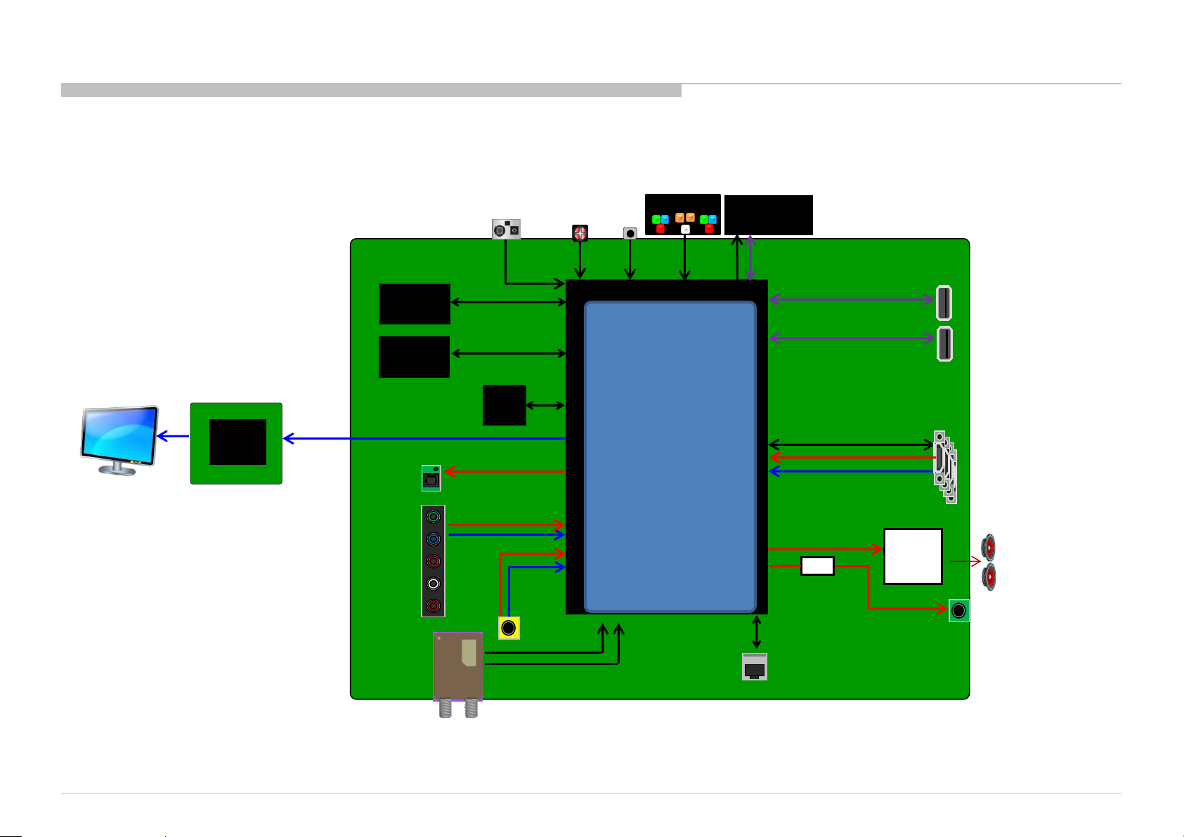
SEC 4. DIAGRAMS
4-1. BLOCK DIAGRAM
4-1-1. BR, AR, LA Model
120Hz
XM-H: Active 3D
FRC+Tcon
(120Hz)
LVDS
/60Hz
BMX
DDR3
2.5GB (4Gb×5)
eMMC
16GB
LVDS
SPDIF
Key
GPIO
u-Con.
OptSens
GPIO
S-mini
LED
GPIO
Muffin
GPIO
Sircs
SIRCS
ARM Cortex A12 dual
core
Cortex-A12 NEON
X-Reality Pro
Multi-format Decoder.
3D OpenGL ES3.0, DX11
DRAM Controller
USB×4
HDMI 1.4a, MHL2.0
LVDS/V-by-One
TCON,
Local Dimming
Video Processor
Audio Processor
2D/3D Converter
DEMOD(ATSC,DVB-T/C)
ADC/DAC
Ethernet MAC+PHY
IF
TS
WIFI &
Bluetooth
USB2.0
HDMI
AMP
I2S
USB2.0
USB2.0
HDMI×4
Audio
P-AMP
BD28620
USB1
USB2 /
HDD
HDMI 1.4
/ MHL2.0
SP
2ch
HP
L/R
Out
KDL-65W850C, 855C, 857C, 75W850C, 855C
Ether
50
Page 51
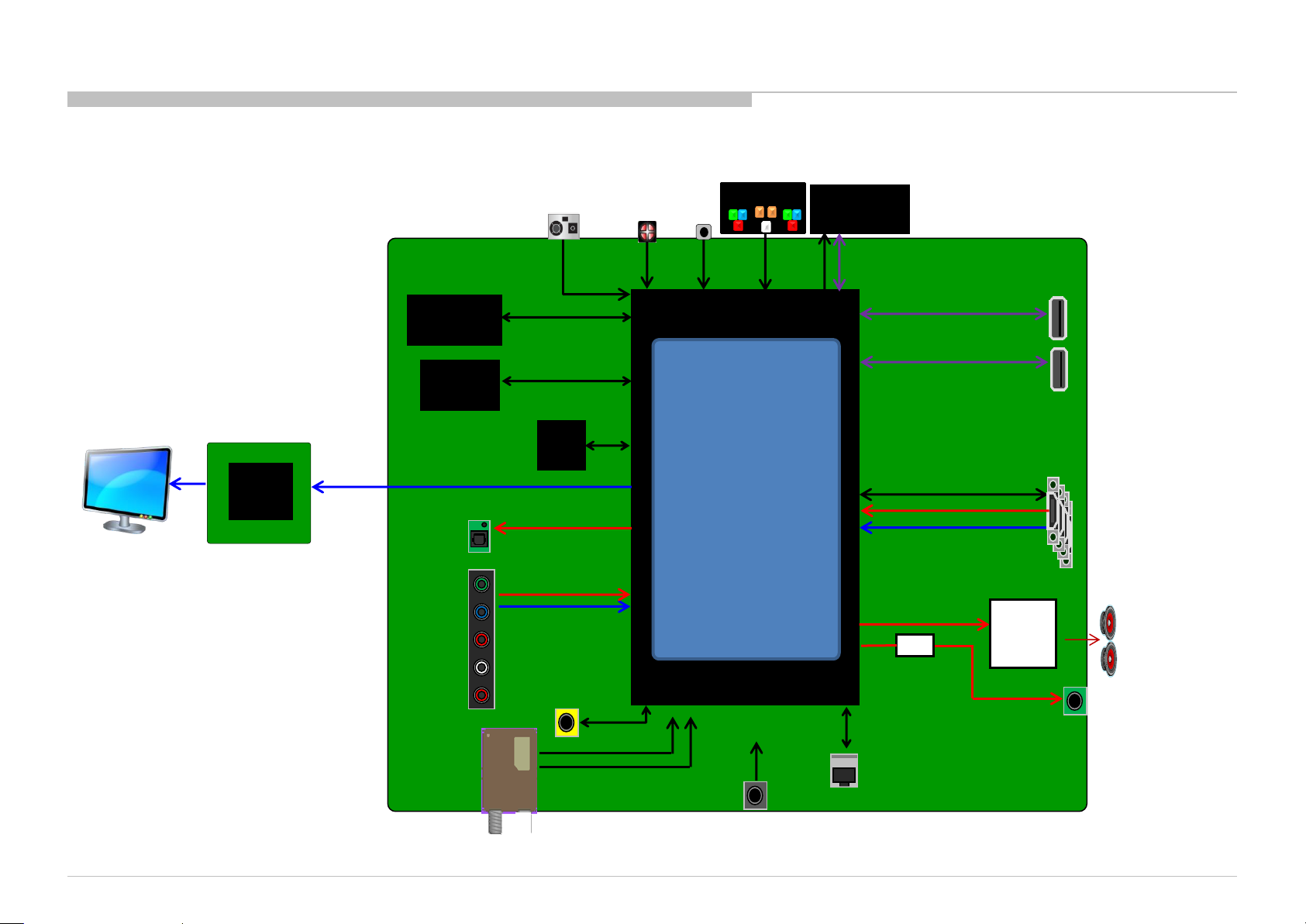
4-1-2. UC Model
DIAGRAMS
120Hz
XM-H: Active 3D
FRC+Tcon
(120Hz)
LVDS
/60Hz
BMX
DDR3
2.5GB (4Gb×5)
eMMC
16GB
LVDS
SPDIF
Key
GPIO
u-Con.
OptSens
GPIO
LED
GPIO
Muffin
GPIO
Sircs
SIRCS
ARM Cortex A12 dual
core
Cortex-A12 NEON
X-Reality Pro
Multi-format Decoder.
3D OpenGL ES3.0, DX11
DRAM Controller
USB×4
HDMI 1.4a, MHL2.0
LVDS/V-by-One
TCON,
Local Dimming
Video Processor
Audio Processor
2D/3D Converter
DEMOD(ATSC,DVB-T/C)
ADC/DAC
Ethernet MAC+PHY
WIFI &
Bluetooth
USB2.0
HDMI
AMP
I2S
USB2.0
USB2.0
HDMI×4
Audio
P-AMP
BD28620
USB1
USB2 / HDD
HDMI 1.4
/ MHL2.0
SP
2ch
KDL-65W850C, 855C, 857C, 75W850C, 855C
S-mini
RS232
IF
SIRCS
TS
C4 Sircs in
HP
L/R
Out
Ether
51
Page 52
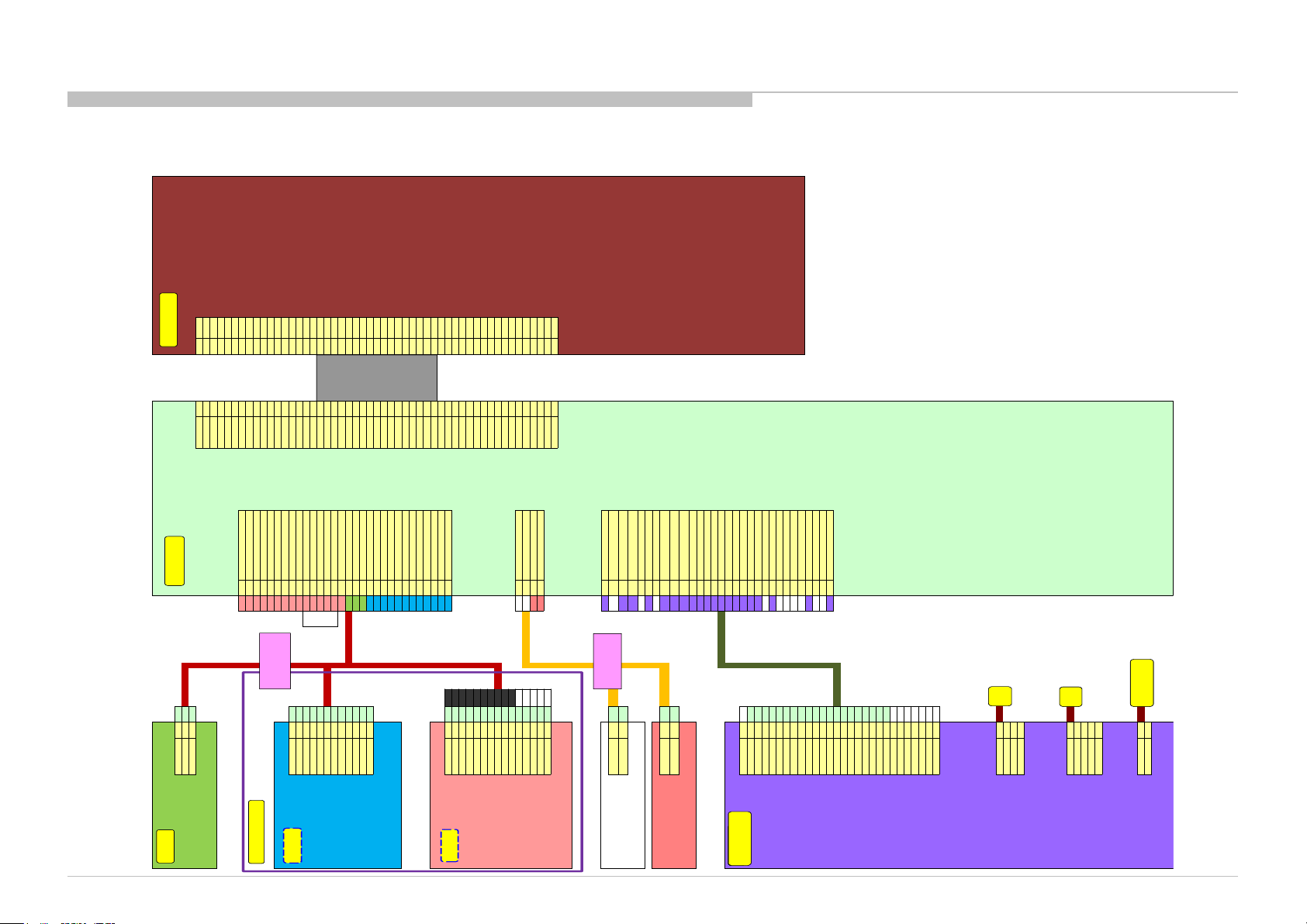
4-2. CONNECTOR DIAGRAM
CN203
1-798-511-11 HUS_POWER_KEY 3 18
HUS_KEY_AD 2 16
HUS_GND 1 17 CN8400 AU O: JAE FT-RTE51SZ-HF
Header : 1-821-143-11 Housing:
1-821-117-11
SPI_CS 1 51 SPI_CS
JAM SYT10-3WL SYT10-03HG FRC_RST 2 50 FRC_RST
Terminal:
1-821-116-11
SPI_CK 3 49 SPI_CK
710112-2MAC NC 4 48 (3D_EN) no need to connect to B board
SPI_DO 5 47 SPI_DI To T con flash
CN1000 LUT_SEL/SPI_DI 6 46 SPI_DO From T con fla sh
1 1 WIFI_GND SA_MODE 7 45 Aging
2 2 WIFI_BT _RST LVDS_SEL 8 44 (SPI_ENB) no need to connect to B board
3 3 WIFI_WAKEUP BINT/WP 9 43 WP
4 4 BT_WAKEUP 3D_SYNC 10 42 3D_SYNC
5 5 WIFI_GND SDA 11 41 SDA
6 6 WIFI_STB Y_3.3V SCL 12 40 SCL
CN101 7 7 WIFI_STB Y_3.3V PANEL_DET 13 39 GND
STBY3.3V 1 23 8 8 WIFI_STBY _3.3V BIN[4]P 14 38 CH2_4+
5V_MAIN 2 20 9 9 WIFI_GND BIN[4]N 15 37 CH2_4-
GND 3 25 11 10 BT _3D_LR BIN[3]P 16 36 CH2_3+
A-2066-086-A LED_AMBER 4 22 10 11 WIFI_GND BIN[3]N 17 35 CH2_3-
LED_PWM_W 5 24 14 12 WIFI_USB_M GND 18 34 GND
LED_PWM_R 6 30 13 13 WIFI_GND BCLK+ 19 33 CH2_CLK+
LED_PWM_B 7 28 15 14 WIFI_USB_P BCLK- 20 32 CH2_CLK-
LED_PWM_G 8 26 12 15 WIFI_GND GND 21 31 GND
GND 9 27 2 16 HUS_KEY _AD BIN[2]P 22 30 CH2_2+
MAIN_3.3V 10 29 1 17 HUS_GND BIN[2]N 23 29 CH2_2-
OPT_SENSE 11 19 3 18 HUS_POWER_KEY BIN[1]P 24 28 CH2_1+
SIRCS 12 21 11 19 SC_OPT_SENSE BIN[1]N 25 27 CH2_1-
Header: 1-821-139-11 Housing:
1-821-126-11
2 20 5V_MAIN BIN[0]P 26 26 CH2_0+
JAM SYT10-12WS SYT10-12HG 12 21 SC_SIRCS BIN[0]N 27 25 CH2_0-
Terminal:
1-821-116-11
4 22 SC_LED_AMBER GND 28 24 GND
710112-2MAC 1 23 SC_STBY_3.3V AIN[4]P 29 23 CH1_4+
5 24 SC_LED_PWM_W AIN[4]N 30 22 CH1_4-
3 25 SC_GND AIN[3]P 31 21 CH1_3+
8 26 SC_LED_PWM_G AIN[3]N 32 20 CH1_3-
9 27 SC_GND GND 33 19 GND
7 28 SC_LED_PWM_B ACLK+ 34 18 CH1_CLK+
USB CABLE 10 29 SC_MAIN_3.3V ACLK- 35 17 CH1_CLK-
GND 1 1 #30 6 30 SC_LED_PWM_R GND 36 16 GND
RST_L 2 2 #30 Housing: Header: 1-820-162-12 AIN[2]P 37 15 CH1_2+
WOW_L 3 3 #30 AIN[2]N 38 14 CH1_2-
WOBT_L 4 4 #30 T erminal: AIN[1]P 39 13 CH1_1+
GND 5 5 #28 AIN[1]N 40 12 CH1_1-
VCC 6 6 #28 AIN[0]P 41 11 CH1_0+
VCC 7 7 #28 AIN[0]N 42 10 CH1_0-
VCC 8 8 #28 GND 43 9 GND
GND 9 9 #28 GND 44 8 GND
GND 10 11 #28 CN7751 GND 45 7 GND
VSYNC 11 10 RED#28 1 1 MAIN L+ NC 46 6 N.C.
GND 12 15 Shield 2 2 M AIN L- PANEL_VCC 47 5 VDD
GND 13 13 BLK#28 1 3 MAIN R+ PANEL_VCC 48 4 VDD
DM 14 12 WHT#28 2 4 MAIN R- PANEL_VCC 49 3 VDD
DP 15 14 GRN#28 Housing: 1-842-593-11 Header: 1-842-566-12 PANEL_VCC 50 2 VDD
Header: 1-819-332-11 Housing:
1-819-502-11
JST PBVP-04V-S JST SM04B-PBVSS-TB(LF)(SN) PANEL_VCC 51 1 VDD
JST SM15B-GHS-TB(LF)(SN) GHR-15V-S
Terminal:
1-819-513-11 Header: 1-843-107-11
Terminal:
1-819-512-11
SPHD-001T-P0.5
SSHL-002T-P0.2
CN9000
Faston #187 5 30 STBY +3v3
SPEAKER
L+ 1 1 NC 29 +3. 3V_STBY_S
Front
L- 2 2 3 28 BL_ON/ICSPCLK
Lch
Faston #110 4 27 VLED_REF/PWM_DIMMER/TM_SCL
NC 26 +3.3V_ST BY_B/19.5_ON
6 25 PWM_4/BLINKING/SPI0_MOSI
Faston #187 NC 24 DC_SENSE
SPEAKER
R+ 1 3 8 23 BL_ERR
Front
R- 2 4 9 22 POWER_ON/ISCPDAT
Rch
Faston #110 10 21 GND
11 20 GND
12 19 GND
13 18 REG12/19.5V_AU
14 17 REG12V/19.5_SS
15 16 REG12V/19.5_AU
16 15 REG12V/19.5_SS
CN6401 17 14 REG12V
(CN2) NC 1 NC 18 13 REG12V
DC_DIMMER 2 4 19 12 GND
BL_ON 3 28 20 11 GND
PWM_DIMMER 4 27 NC 10 VPP_PIC
STBY3.3V 5 30 21 9 GND
BLINKING 6 25 NC 8 T CON_ON/TM_LOG_RX
AC_OFF_DET 7 1 NC 7 PANEL_PWR_DET/TM_LOG_TX
BL_ERR 8 23 NC 6
LD_MODE_SW/SA_MODE
POWER_ON 9 22 NC 5 PWM_5/SPI0_SCK
GND 10 21 2 4 IP_REF/DC_DIMMER/T M_SDA
GND 11 20 NC 3 PWM_3/TM_EMIT
GND 12 19 NC 2 PWM_2/SPI0_nCS
REG12V 13 18 7 1 AC_OFF_DET
REG12V 14 17 Housing: Header: 1-843-953-11
REG12V 15 16
REG12V 16 15 Terminal:
REG12V 17 14
REG12V 18 13
GND 19 12
GND 20 11
GND 21 9
GND 22 NC
GND 23 NC
NC 24 NC
NC 25 NC
NC 26 NC
NC 27 NC
NC 28 NC
Header: 1-842-551-11 Housing:
Terminal:
CN6801
(CN3) +OUT 1 1
+OUT2 2
NC 3
NC 4
Header: 1-822-359-11 Housing:
Terminal:
CN6802
-OUT1 1
(CN4) -OUT 2 2
NC 3
NC 4
NC 5
Header: 1-822-360-11 Housing:
Terminal:
CN6101
(CN1) AC-N 1
AC-L 2
Header: 1-822-908-11 Housing:
Terminal:
USB
BMX Board
Wifi/BT
SM
GN1 Smart Core
HSC3-L
G BoardG BoardG Board
GL1SB Board
T-Con Board
LS
LS
AC pigtail
51pin FFC
Main Harness
SPK Harness
4-2-1. 65 Inch Model
DIAGRAMS
KDL-65W850C, 855C, 857C, 75W850C, 855C
52
Page 53
CN203
1-798-511-11 HUS_POWER_KEY 3 18
HUS_KEY_AD 2 16
HUS_GND 1 17 CN8400
SDC:JAE FI-RXE51S-HF
Header : 1-821-143-11 Housing:
1-821-117-11
SPI_CS 1 51 SPI_CS
JAM SYT10-3WL SYT10-03HG FRC_RST 2 50 FRC_RST
Terminal:
1-821-116-11
SPI_CK 3 49 SPI_CK
710112-2MAC NC 4 48 (3D_EN) no need to connect to B board
SPI_DO 5 47 SPI_DI To T con flash
CN1000 LUT_SEL/SPI_DI 6 46 SPI_DO From T con fla sh
1 1 WIFI_GND SA_MODE 7 45 Aging
2 2 WIFI_BT _RST LVDS_SEL 8 44 (SPI_ENB) no need to connect to B board
3 3 WIFI_WAKEUP BINT /WP 9 43 WP
4 4 BT_WAKEUP 3D_SYNC 10 42 3D_SYNC
5 5 WIFI_GND SDA 11 41 SDA
6 6 WIFI_STB Y_3.3V SCL 12 40 SCL
CN101 7 7 WIFI_STB Y_3.3V PANEL_DET 13 39 GND
STBY3.3V 1 23 8 8 WIFI_STBY _3.3V BIN[4]P 14 38 CH2_4+
5V_MAIN 2 20 9 9 WIFI_GND BIN[4]N 15 37 CH2_4-
GND 3 25 11 10 BT_3D_LR BI N[3]P 16 36 CH2_3+
A-2066-086-A LED_AMBER 4 22 10 11 WIFI_GND BIN[3]N 17 35 CH2_3-
LED_PWM_W 5 24 14 12 WIFI_USB_M GND 18 34 GND
LED_PWM_R 6 30 13 13 WIFI_GND BCLK+ 19 33 CH2_CLK+
LED_PWM_B 7 28 15 14 WIFI_USB_P BCLK- 20 32 CH2_CLK-
LED_PWM_G 8 26 12 15 WIFI_GND GND 21 31 GND
GND 9 27 2 16 HUS_KEY _AD BIN[2]P 22 30 CH2_2+
MAIN_3.3V 10 29 1 17 HUS_GND BIN[2]N 23 29 CH2_2-
OPT_SENSE 11 19 3 18 HUS_POWER_KEY BIN[1]P 24 28 CH2_1+
SIRCS 12 21 11 19 SC_OPT_SENSE BIN[1]N 25 27 CH2_1-
Header: 1-821-139-11 Housing:
1-821-126-11
2 20 5V_MAIN BIN[0]P 26 26 CH2_0+
JAM SYT10-12WS SYT10-12HG 12 21 SC_SIRCS BIN[0]N 27 25 CH2_0-
Terminal:
1-821-116-11
4 22 SC_LED_AMBER GND 28 24 GND
710112-2MAC 1 23 SC_STBY_3.3V AIN[4]P 29 23 CH1_4+
5 24 SC_LED_PWM_W AIN[4]N 30 22 CH1_4-
3 25 SC_GND AIN[3]P 31 21 CH1_3+
8 26 SC_LED_PWM_G AIN[3]N 32 20 CH1_3-
9 27 SC_GND GND 33 19 GND
7 28 SC_LED_PWM_B ACLK+ 34 18 CH1_CLK+
USB CABLE 10 29 SC_MAIN_3.3V ACLK- 35 17 CH1_CLK-
GND 1 1 #30 6 30 SC_LED_PWM_R GND 36 16 GND
RST_L 2 2 #30 Housing: Header: 1-820-162-12 AIN[2]P 37 15 CH1_2+
WOW_L 3 3 #30 AIN[2]N 38 14 CH1_2-
WOBT_L 4 4 #30 T erminal: AIN[1]P 39 13 CH1_1+
GND 5 5 #28 AIN[1]N 40 12 CH1_1-
VCC 6 6 #28 AIN[0]P 41 11 CH1_0+
VCC 7 7 #28 AIN[0]N 42 10 CH1_0-
VCC 8 8 #28 GND 43 9 GND
GND 9 9 #28 GND 44 8 GND
GND 10 11 #28 CN7751 GND 45 7 GND
VSYNC 11 10 RED#28 1 1 MAIN L+ NC 46 6 N.C.
GND 12 15 Shield 2 2 M AIN L- PANEL_VCC 47 5 VDD
GND 13 13 BLK#28 1 3 MAIN R+ PANEL_VCC 48 4 VDD
DM 14 12 WHT#28 2 4 MAIN R- PANEL_VCC 49 3 V DD
DP 15 14 GRN#28 Housing: 1-842-593-11 Header: 1-842-566-12 PANEL_VCC 50 2 VDD
Header: 1-819-332-11 Housing:
1-819-502-11
JST PBVP-04V-S JST SM04B-PBVSS-TB(LF)(SN) PANEL_VCC 51 1 VDD
JST SM15B-GHS-TB(LF)(SN) GHR-15V-S
Terminal:
1-819-513-11 Header: 1-843-107-11
Terminal:
1-819-512-11
SPHD-001T-P0.5
SSHL-002T-P0.2
CN9000
Faston #187 5 30 STBY +3v3
SPEAKER
L+ 1 1 NC 29 +3. 3V_STBY_S
Front
L- 2 2 3 28 BL_ON/ICSPCLK
Lch
Faston #110 4 27 VLED_REF/PWM_DIMMER/TM_SCL
NC 26 +3.3V_ST BY_B/19.5_ON
6 25 PWM_4/BLINKING/SPI0_MOSI
Faston #187 NC 24 DC_SENSE
SPEAKER
R+ 1 3 8 23 BL_ERR
Front
R- 2 4 9 22 POWER_ON/ISCPDAT
Rch
Faston #110 10 21 GND
11 20 GND
12 19 GND
13 18 REG12/19.5V_AU
14 17 REG12V/19.5_SS
15 16 REG12V/19.5_AU
16 15 REG12V/19.5_SS
CN6401 17 14 REG12V
(CN2) NC 1 NC 18 13 REG12V
DC_DIMMER 2 4 19 12 GND
BL_ON 3 28 20 11 GND
PWM_DIMMER 4 27 NC 10 VPP_PIC
STBY3.3V 5 30 21 9 GND
BLINKING 6 25 NC 8 T CON_ON/TM_LOG_RX
AC_OFF_DET 7 1 NC 7 PANEL_PWR_DET/TM_LOG_TX
BL_ERR 8 23 NC 6
LD_MODE_SW/SA_MODE
POWER_ON 9 22 NC 5 PWM_5/SPI0_SCK
GND 10 21 2 4 IP_REF/DC_DIMMER/T M_SDA
GND 11 20 NC 3 PWM_3/TM_EMIT
GND 12 19 NC 2 PWM_2/SPI0_nCS
REG12V 13 18 7 1 AC_OFF_DET
REG12V 14 17 Housing: Header: 1-843-953-11
REG12V 15 16
REG12V 16 15 Terminal:
REG12V 17 14
REG12V 18 13
GND 19 12
GND 20 11
GND 21 9
GND 22 NC
GND 23 NC
NC 24 NC
NC 25 NC
NC 26 NC
NC 27 NC
NC 28 NC
Header: 1-842-551-11 Housing:
Terminal:
CN6801
(CN3) +OUT 1 1
+OUT2 2
+OUT3 3
+OUT4 4
Header: 1-822-359-11 Housing:
Terminal:
CN6802
-OUT1 1
(CN4) -OUT 2 2
-OUT3 3
-OUT4 4
NC 5
Header: 1-822-360-11 Housing:
Terminal:
CN6101
(CN1) AC-N 1
AC-L 2
Header: 1-822-908-11 Housing:
Terminal:
USB
BMX Board
Wifi/BT
SM
GN1 Smart Core
HSC3-L
G BoardG BoardG Board
GL1C Board
T-Con Board
LS
LS
AC pigtail
51pin FFC
Main Harness
SPK Harness
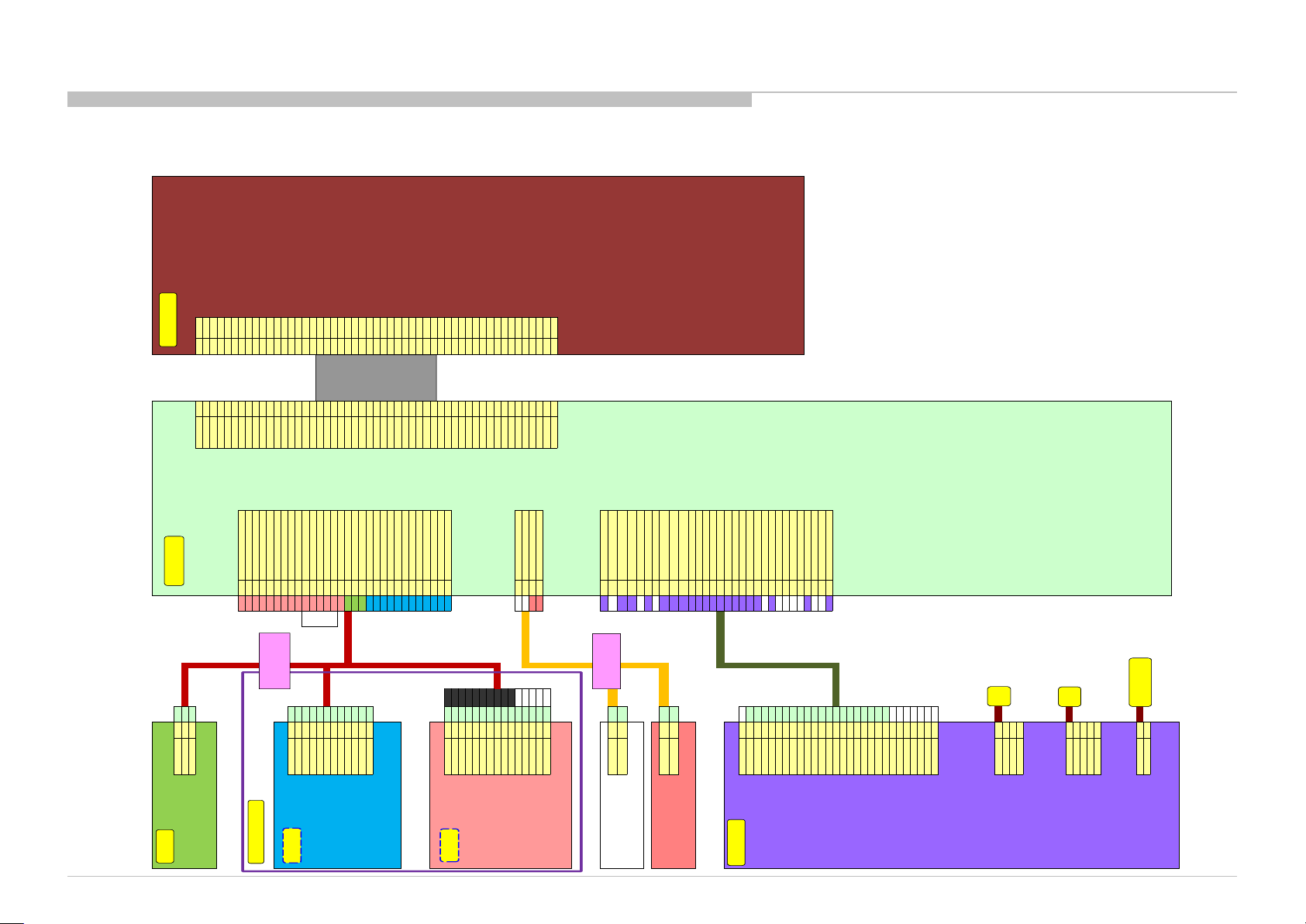
DIAGRAMS
4-2-2. 75 Inch Model
KDL-65W850C, 855C, 857C, 75W850C, 855C
53
Page 54
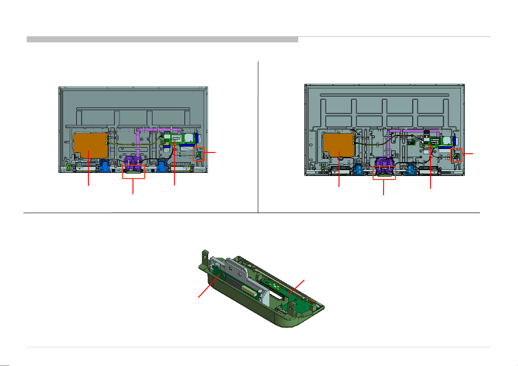
4-3. CIRCUIT BOARDS LOCATION
4-3-1. KDL-65W850C/855C/857C 4-3-2. KDL-75W850C/855C
DIAGRAMS
GL1SB BOARD
** SMART CORE BLOCK
BMX BOARD
WLAN/BT
MODULE(11N)
SWITCH
UNIT
<** SMART CORE BLOCK >
GL1SC BOARD
HSC3_L
MOUNT
SWITCH
UNIT
BMX BOARD
** SMART CORE BLOCK
KDL-65W850C, 855C, 857C, 75W850C, 855C
54
Page 55
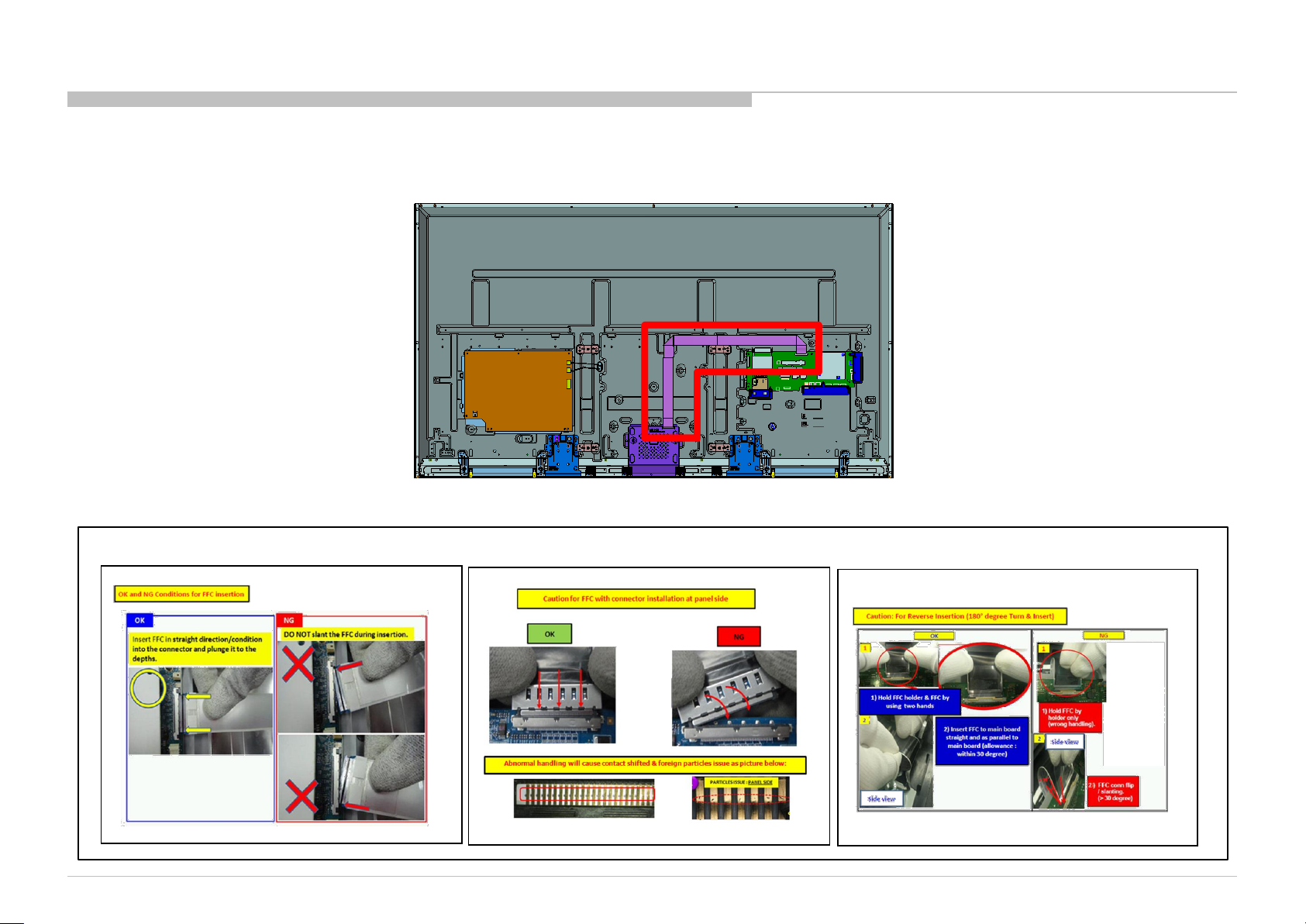
4-4. Wire Dressing
4-4-1. Wire Dressing (Caution for Flexible Flat Cable)
DIAGRAMS
KDL-65W850C, 855C, 857C, 75W850C, 855C
Caution during handling Flexible Flat Cable
55
Page 56
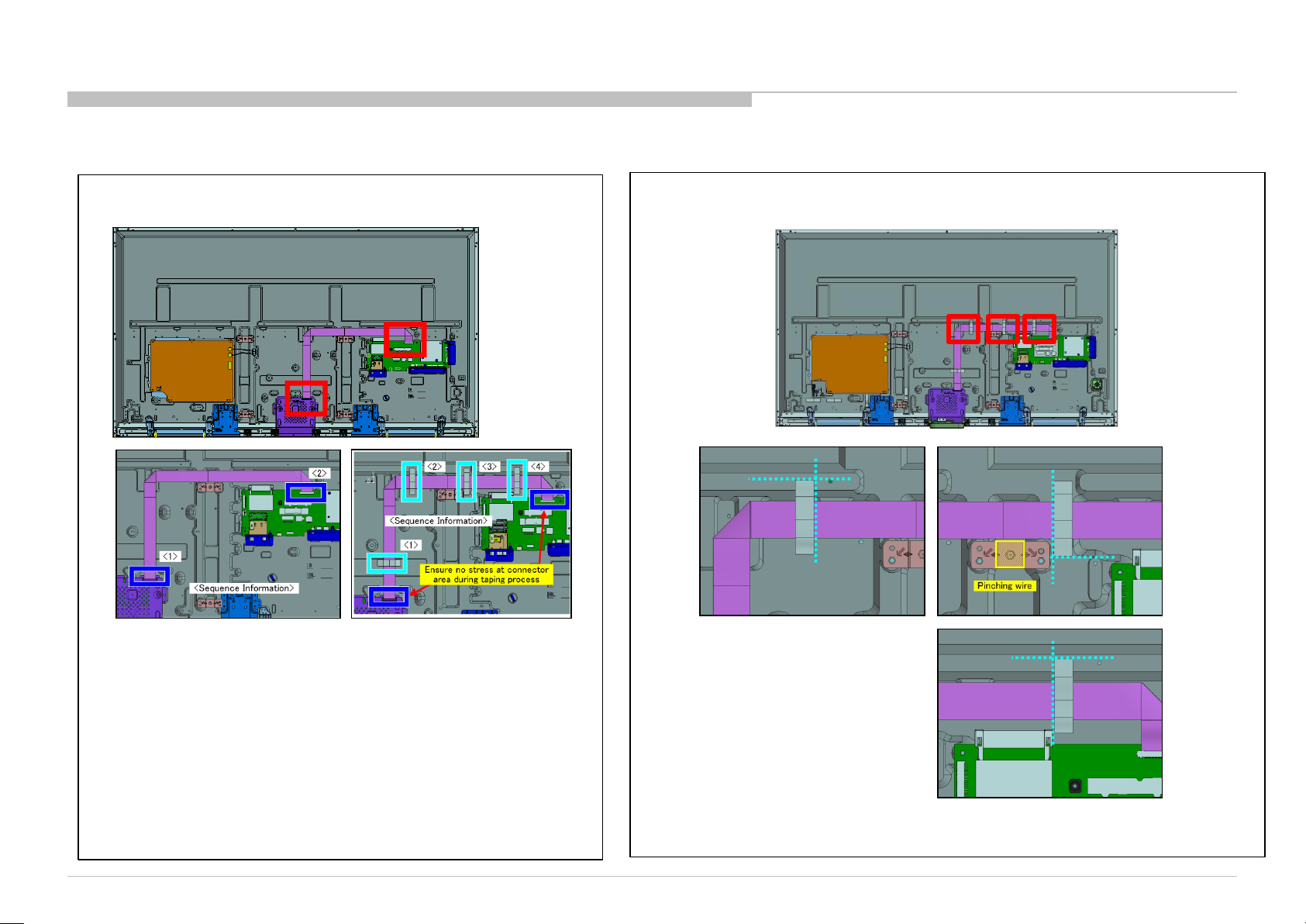
4-4-2. Wire Dressing (Insert Connector & Tape (FFC))
DIAGRAMS
Insert Connector
Insert Tape
KDL-65W850C, 855C, 857C, 75W850C, 855C
56
Page 57
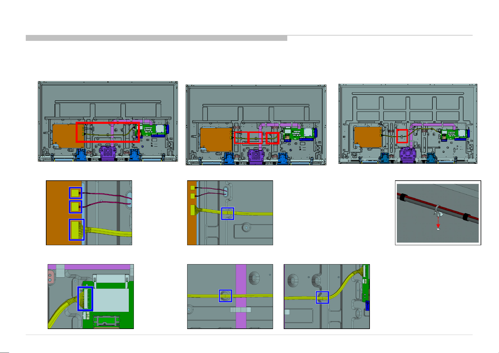
4-4-3. Wire Dressing (Insert Connector, Tape & Hook(Harness))
DIAGRAMS
Insert Connector at GL1B/C Board
Hook Area
Insert tape
Insert Connector at BMX Board
KDL-65W850C, 855C, 857C, 75W850C, 855C
57
Page 58
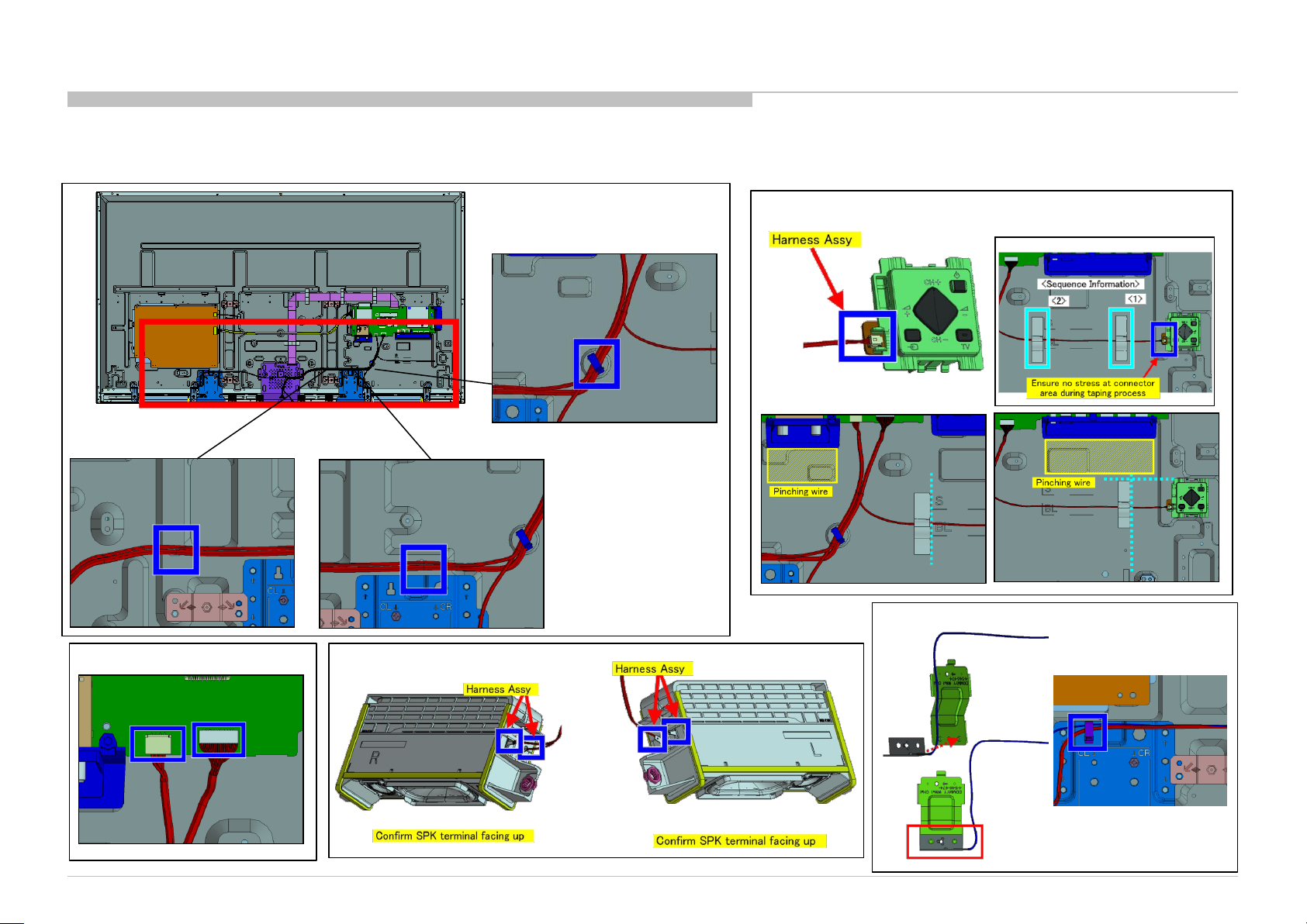
4-4-4. Wire Dressing (Switch Assy, BMX Board, Speaker Box Assy & BT Antenna)
Hook
Hook
DIAGRAMS
Switch Assy
BMX Board
Insert Connector
KDL-65W850C, 855C, 857C, 75W850C, 855C
BT Antenna
Speaker Box Assy
58
Page 59
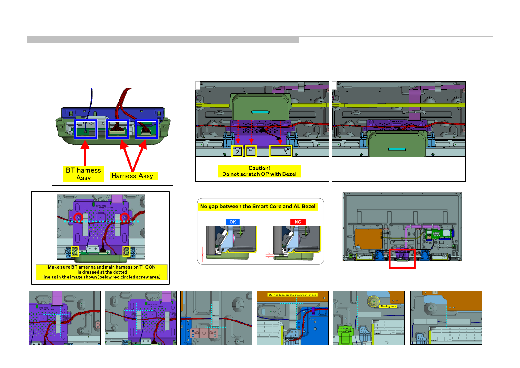
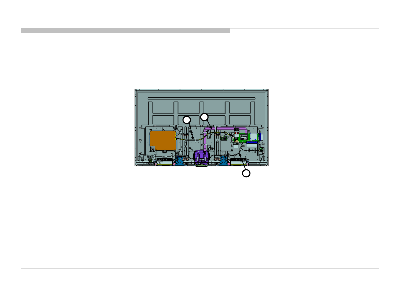
4-4-5. Wire Dressing (Smart core)
DIAGRAMS
1 2
KDL-65W850C, 855C, 857C, 75W850C, 855C
59
Page 60
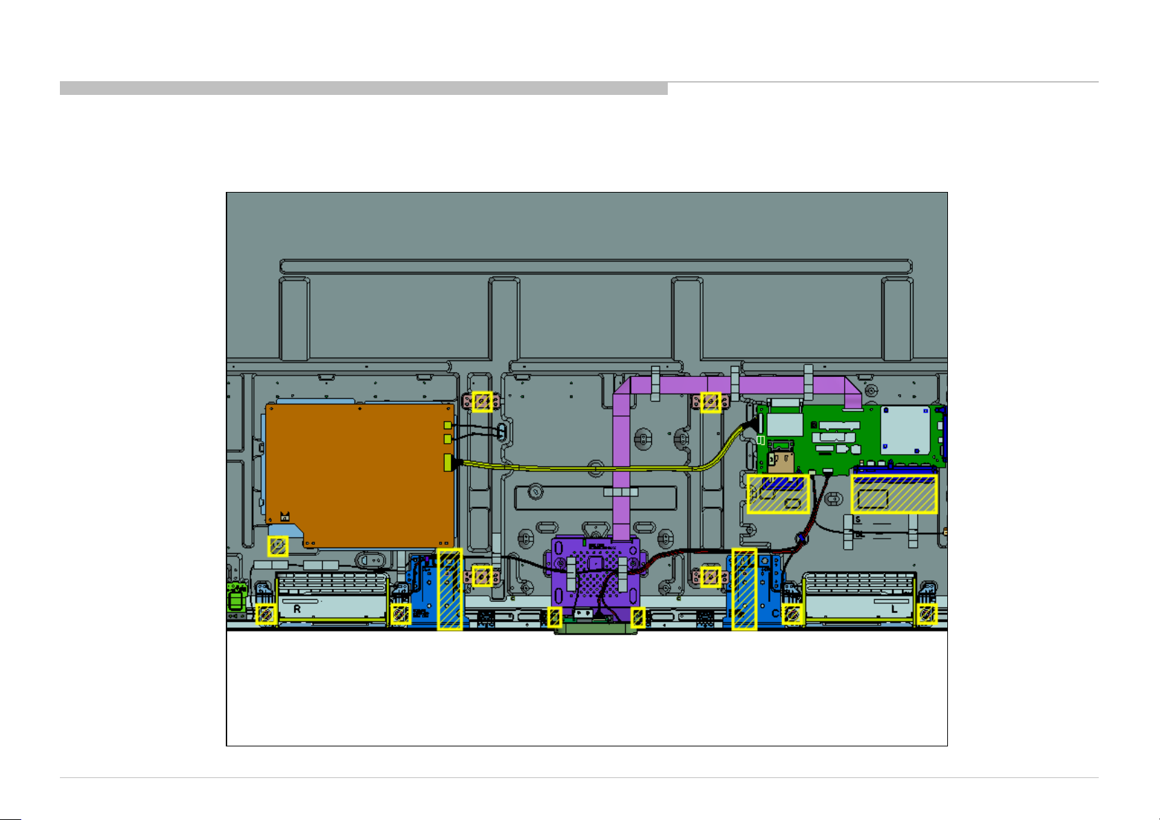
4-4-6. Wire Dressing (Harness Caution Point (Pinching Wire area))
DIAGRAMS
KDL-65W850C, 855C, 857C, 75W850C, 855C
PINCHING WIRE CAUTION AREA
Please take caution as the wire will be easily pinched and the yellow block area
60
Page 61

END
9-888-168-A1
KDL-65W850C, 855C, 857C, 75W850C, 855C
Sony Visual Products Inc.
English
2015CL08-Data
Made in Japan
© 2015. 3
61
Page 62
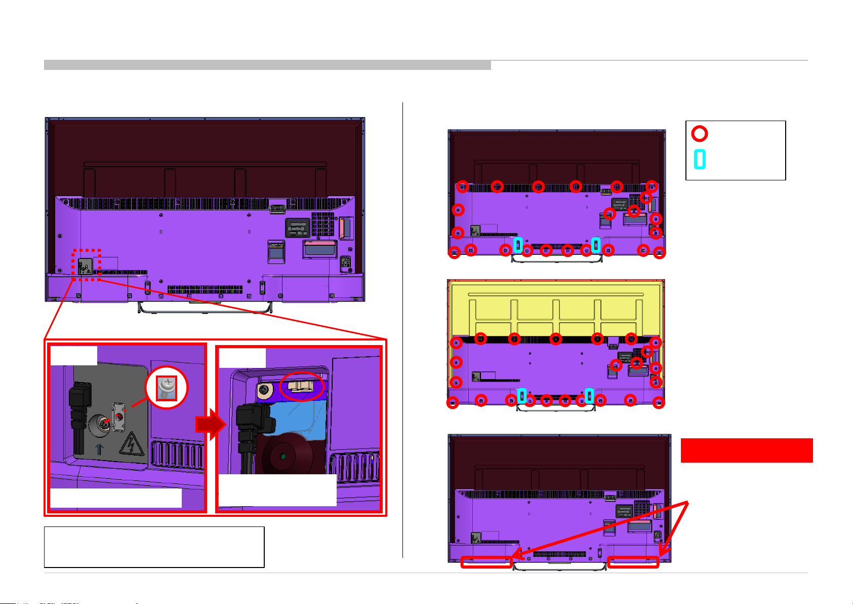
APPENDIX-1
1-1. Procedure To Disassemble Under Cover (Standing position)
1-1-1. Remove AC Cover 1-1-2. Disassemble screw (Without stand screw)
a. 65” model
b. 75” model
X 23
X 4
(Stand screw)
STEP1
REMOVE SCREW
Confirm all screws & positions before removing
them.
Screws detail refer to Section 3
KDL-65W850C, 855C, 857C, 75W850C, 855C
STEP2
REMOVE AC COVER
& CONNECTOR
1-1-3. Disassemble Under Cover
by two people
Please take out same timing
both side Under Cover
62 62
Page 63
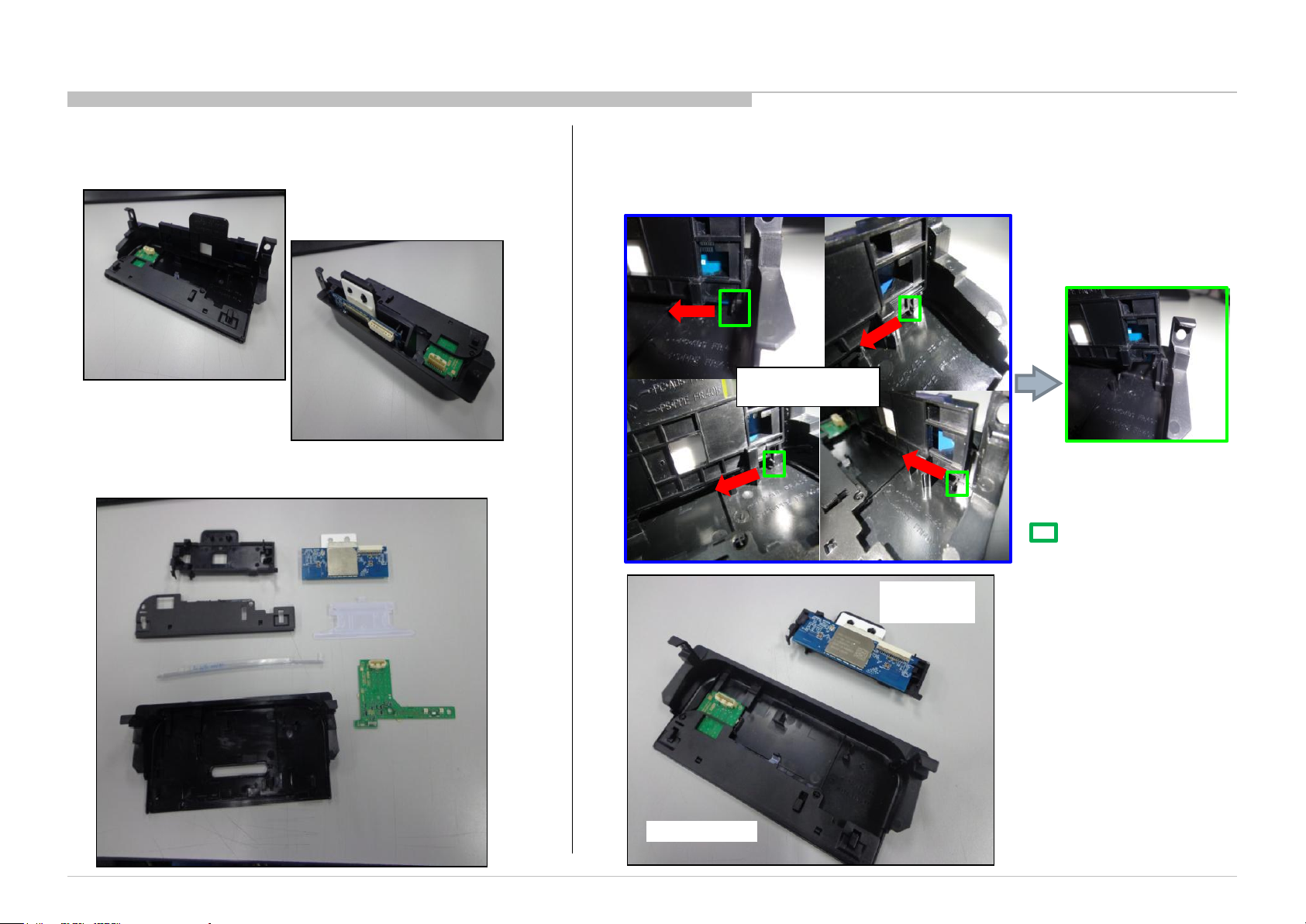
1-2. Procedure To Disassemble Smart Core
1-2-1. General
BACK VIEW
FRONT VIEW
SMART CORE PARTS
APPENDIX-1
1-2-2. Smart Core Disassembly
Step 1 : Remove WIRELESS CASE by pulling the hook in the direction as shown
HOOK PULL
DIRECTION
BRACKE
T, WIFI
COVER,
TOP
PANEL,
ORNAMENT
CASE,
BOTTOM (L)
KDL-65W850C, 855C, 857C, 75W850C, 855C
WIFI
BOARD
LIGHT,
GUIDE
HSC3L
: Hook location
WIRELESS
CASE
LIGHT CASE
63
Page 64
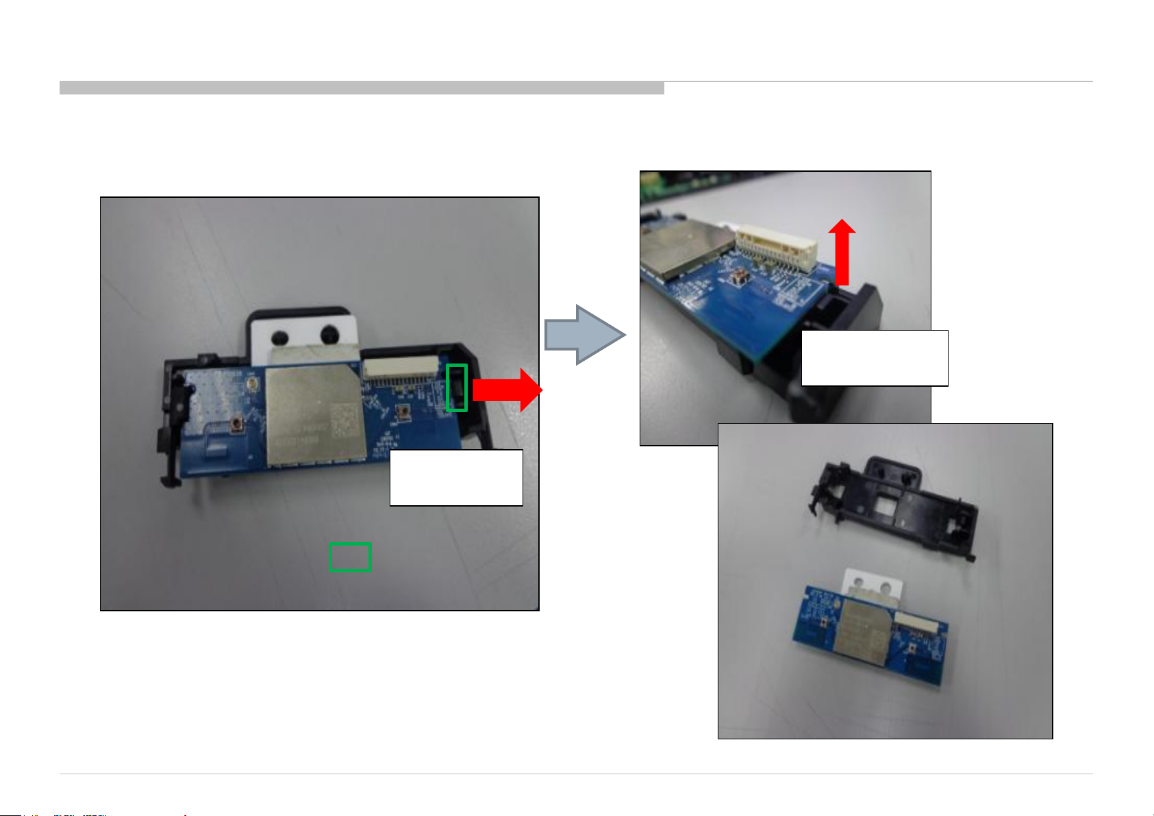
1-2-3. Wireless Case Disassembly
Step 1 : Detach from hook (1 location)
APPENDIX-1
Step 2 : Remove wifi board
REMOVE WIFI
BOARD
PULL
DIRECTION
KDL-65W850C, 855C, 857C, 75W850C, 855C
: Hook location
64
Page 65
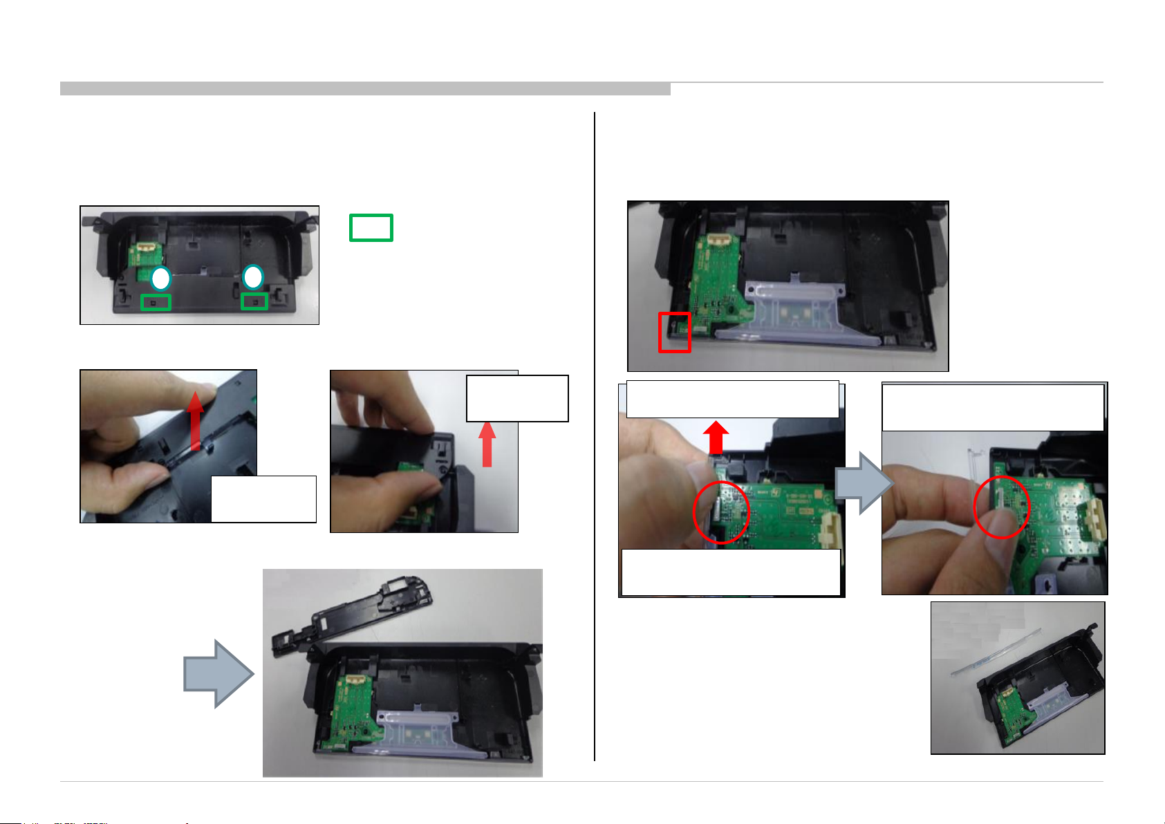
1-2-4. Light Case Disassembly
a) Disassembly of “COVER, TOP”
APPENDIX-1
b) Disassembly of “Panel, Ornamental”
Take out from hook (2 location) *take out hook from “No.1” to “No.2”.
: Hook location
2
Take out hook at No.1 area
1
Take out hook at No.2 area
PULL
DIRECTION
PULL
DIRECTION
After detach No.1 hook, Detach No.2 hook.
Detach “PANEL, ORNAMENT” as shown below
Hook location
Lift the hook (Y-Direction) to
release from rib.
touching board components
Caution Point: Avoid
touching board components
Caution Point: Avoid
KDL-65W850C, 855C, 857C, 75W850C, 855C
65
Page 66
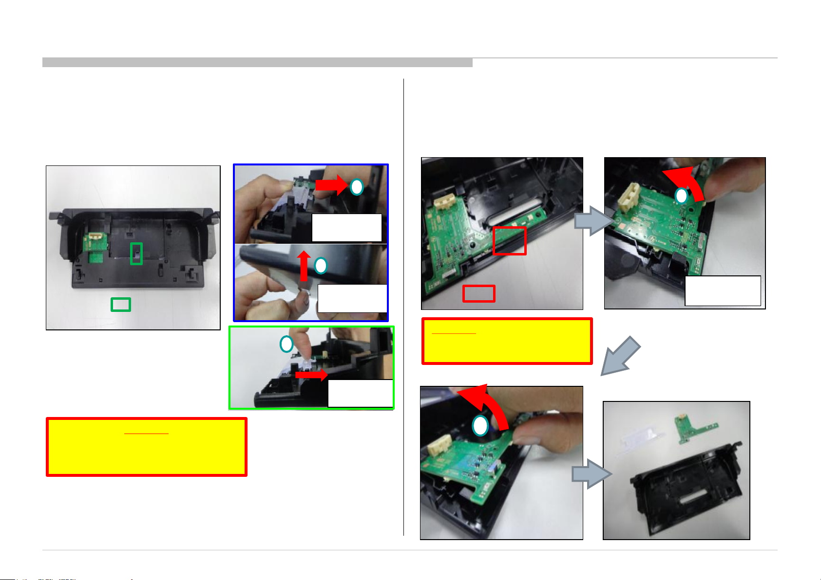
APPENDIX-1
c) Disassembly of “Light, Guide”
Detach LIGHT, GUIDE from hook and push LIGHT, GUIDE from bottom
simultaneously
1
PULL
DIRECTION
1
PUSH
: Hook
DIRECTION
location
Step 3.2 : Pull the LIGHT, GUIDE
2
inwards to remove it
PULL
DIRECTION
d) Disassembly of “HSC3L Mount Board”
: Location to pull
Remarks:
Do not pull on any components
on HSC PWB!
1
PULL
DIRECTION
Remarks:
Step 2 is important to avoid hook
broken from Case, Bottom and Light,
Guide.
KDL-65W850C, 855C, 857C, 75W850C, 855C
2
66
 Loading...