

Page 1

HISTORY INFORMATION FOR THE FOLLOWING MANUAL:
SERVICE MANUAL
MODEL NAME REMOTE COMMANDER DESTINATION
KDL-52S5100
KDL-52S5100
KDL-52V5100
KDL-52V5100
RM-YD028 US/CND
RM-YD028 MX/LATIN AMERICA
RM-YD028 US/CND
RM-YD028 MX/LATIN AMERICA
EX2R
CHASSIS
ORIGINAL MANUAL ISSUE DATE: 2/2009
:UPDATED ITEM
☛
REVISION DATE SUBJECT
2/2009 No revisions or updates are applicable at this time.
3/2009 (D6) Insulation Sheet added to Exploded View. Replaced page 82.
Added USB information to Specifi cations Section. Replaced page 4.
6/2009 Added Support Belt Kit contents to Miscellaneous Section of Parts List. Replaced page 102.
9/2009 Updated Exploded View Section to remove LCD Panel specifi c information. Replaced pages 82-83.
LCD DIGITAL COLOR TELEVISION
9-883-811-04
Page 2
Self Diagnosis
Supported model
SERVICE MANUAL
MODEL NAME REMOTE COMMANDER DESTINATION
KDL-52S5100
KDL-52S5100
KDL-52V5100
KDL-52V5100
RM-YD028 US/CND
RM-YD028 MX/LATIN AMERICA
RM-YD028 US/CND
RM-YD028 MX/LATIN AMERICA
EX2R
CHASSIS
CCDISPLAY POWER
WIDE INPUT
TOOLS
KDL-52S5100 RM-YD028
9-883-811-04
LCD DIGITAL COLOR TELEVISION
Page 3

KDL-52S5100/52V5100
TABLE OF CONTENTS
SECTION TITLE PAGE SECTION TITLE PAGE
Specifi cations ................................................................................. 4
Warnings and Cautions - English ................................................... 6
Warnings and Cautions - French .................................................... 7
Safety-Related Component Warning .............................................. 8
Safety Check-Out ......................................................................... 10
Self-Diagnostic Function ................................................................11
SECTION 1: DISASSEMBLY ............................................................... 13
1-1. Rear Cover Removal ............................................................ 13
1-2. Switch Unit Removal (Contains HSW3 Board) .................... 13
1-3. BM3 Board, G5N Board, D5N Board,
and D6N Board Removal ..................................................... 14
1-4. Table-Top Stand Assembly and Under Cover Removal ....... 15
1-5. Brackets and Spine Removal ............................................... 16
1-5-1. KDL-52S5100 .......................................................... 16
1-5-2. KDL-52V5100 .......................................................... 17
1-6. Loudspeaker, Under Bar, IR Guide,
and LED Guide Removal ..................................................... 18
1-7. LCD Panel Removal ............................................................. 19
1-7-1. Cleaning the LCD Panel ............................................ 19
WIRE DRESSING ........................................................................ 20
KDL-52S5100 ONLY ............................................................ 20
KDL-5VS5100 ONLY ............................................................ 33
SECTION 2: SERVICE ADJUSTMENTS ............................................. 48
2-1. Viewing Service Adjustment Data ........................................ 48
2-2. Accessing Service Mode ...................................................... 48
2-2-1. Entering the Serial Number
After Changing the Main Board ............................... 48
2-2-2. Resetting to Factory Defaults .................................. 49
SECTION 3: DIAGRAMS ..................................................................... 50
3-1. Circuit Boards Location ........................................................ 50
3-2. Printed Wiring Boards
and Schematic Diagrams Information .................................. 50
3-3. Block Diagram ...................................................................... 52
3-4. Schematics and Supporting Information .............................. 53
BM3 Board Schematic Diagram (1 of 9) .............................. 53
BM3 Board Schematic Diagram (2 of 9) .............................. 54
BM3 Board Schematic Diagram (3 of 9) .............................. 55
BM3 Board Schematic Diagram (4 of 9) .............................. 56
BM3 Board Schematic Diagram (5 of 9) .............................. 57
BM3 Board Schematic Diagram (6 of 9) .............................. 58
BM3 Board Schematic Diagram (7 of 9) .............................. 59
BM3 Board Schematic Diagram (8 of 9) .............................. 60
BM3 Board Schematic Diagram (9 of 9) .............................. 61
D5N Board Schematic Diagram ........................................... 63
D6N Board Schematic Diagram ........................................... 66
G5N Board Schematic Diagram ........................................... 69
HLR1 Board Schematic Diagram (KDL-52S5100 Only) ....... 72
HLR4 Board Schematic Diagram (KDL-52V5100 Only) ....... 74
HSR Board Schematic Diagram ........................................... 76
3-5. Semiconductors ................................................................... 78
SECTION 4: EXPLODED VIEWS ........................................................ 79
4-1. Rear Cover Assembly and Table-Top Stand Assembly ....... 79
4-2. Chassis ............................................................................... 80
4-3. Connectors .......................................................................... 81
4-4. Bezel Assembly and LCD Panel (KDL-52S5100 Only) ....... 82
4-5. Bezel Assembly and LCD Panel (KDL-52V5100 Only) ........ 83
4-6. Screw Legend ...................................................................... 84
SECTION 5: ELECTRICAL PARTS LIST ............................................ 85
KDL-52S5100/52V5100
APPENDIX A: ENCRYPTION KEY COMPONENTS ..........................A-1
3
Page 4
SPECIFICATIONS
KDL-52S5100/52V5100
Power Requirements
Power Consumption (W)
In Use (Max)
In Standby
120V AC, 60Hz
HDMI IN 1/2/3 (KDL-52S5100 ONLY)
HDMI: Video: 480i, 480p, 720p, 1080i,1080p, 1080/24p
Audio: Two channel linear PCM 32, 44.1 and 48 kHz, 16, 20 and 24 bits
295W
HDMI IN 1/2/3/4 (KDL-52V5100 ONLY)
Less than 1 W
HDMI: Video: 480i, 480p, 720p, 1080i,1080p, 1080/24p
Audio: Two channel linear PCM 32, 44.1 and 48 kHz, 16, 20 and 24 bits
VIDEO (IN) 1/2:
S Video (4-Pin Mini DIN (VIDEO 2 Only)
Y: 1.0 Vp-p, 75 ohms unbalanced, sync negative
C: 0.286 Vp-p (Burst signal), 75 ohms
AUDIO
500 mVrms (Typical)
Impedance: 47 kilohms
Video
1 Vp-p, 75 ohms unbalanced, sync negative
Audio
AUDIO OUT:
500 mVrms (Typical)
500 mVrms (Typical)
Impedance:47 kilohms
DIGITAL AUDIO OUT (OPTICAL):
PCM optical signal
COMPONENT IN 1/2:
YP
Y:1.0 Vp-p, 75 ohms unbalanced, sync negative
(Component Video)
BPR
PC IN:
D-sub 15-pin, analog RGB, 0.7 Vp-p, 75 ohms, positive
PB:0.7 Vp-p, 75 ohms
PR:0.7 Vp-p, 75 ohms
Signal format: 480i, 480p, 720p, 1080i, 1080p
AUDIO
PC AUDIO INPUT:
Stereo mini jack, 500 mVrms (Typical)
Impedance: 47 kilohms
500 mVrms (Typical)
Impedance: 47 kilohms
☛
USB:
USB input support mass storage device class (USB MSC) that may include
thumbdrives, hard disks and some MP3 players and cameras. This TV does
not support MTP or PTP protocols used by some MP3 players and cameras.
Supported JPG fi les include those that are compliant with ISO/IEC 10918-1
JPEG specifi cation (8 bit per component, Grayscale/Color, Y:Cb:Cr=4:2:2 or
Y:Cb:Cr=4:2:0, Base line DCT, Non-differential Huffman coding)
and EXIF 2.2. Supported MP3 fi les bit rates in kpbs include 40, 48, 56, 64, 80,
96, 112, 128,160, 192, 224, 256, 320 in both constant and variable rate. Scan
frequencies supported include 32, 44.1 and 48 Khz.
KDL-52S5100/52V5100
Licensing Information
Macintosh is a trademark of Apple Inc.,
registered in the U.S. and other countries.
HDMI, the HDMI logo and
High-Definition Multimedia Interface are
trademarks or registered trademarks of
HDMI Licensing, LLC.
Fergason Patent Properties, LLC:
U.S. Patent No. 5,717,422
U.S. Patent No. 6,816,141
Manufactured under license from Dolby
Laboratories. Dolby and the double-D
symbol are trademarks of Dolby
Laboratories.
TruSurround XT, SRS and (z) symbol are
trademarks of SRS Labs, Inc. TruSurround
XT technology is incorporated under
license from SRS Labs, Inc.
Blu-ray Disc is a trademark.
“BRAVIA”, , BRAVIA Sync
and are trademarks or registered
trademarks of Sony Corporation.
“PLAYSTATION” is a registered
trademark and “PS3” is a trademark of
Sony Computer Entertainment Inc.
Design and specifi cations are subject to change without notice.
4
Page 5
KDL-52S5100/52V5100
3/4
1/4
3/8
3/4
3/8
3/8
KDL-52V5100KDL-52S5100
Speaker Output
Speaker/Full Range (2)
Dimensions (W x H x D)
with stand
without stand
wall-mount hole pattern (mm)
wall-mount screw size (mm)
Mass
with stand
without stand
Television system
NTSC American TV Standard
ATSC (8VSB terrestrial) ATSC compliant 8VSB
QAM on cable ANSI/SCTE 07 2000
Channel coverage
Analog
2-69 Terrestrial
1-135 Cable
Digital
2-69 Terrestrial
1-135 Cable
Antenna
75-ohm external terminal for RF inputs
10 W+ 10 W
mm
in
35 X 175
7/16
1
x 7
mm 1,262 x 869 x 362 mm 1,262 x 871 x 362 mm
in
x 34
x 14
in 49
x 34
x 14
in
49
mm 1,262 x 822 x 115 mm 1,262 x 823 x 115 mm
in
49
3/4
x 32
3/8
5/8
x 4
in 49
3/4
x 32
1/2
x 4
5/8
in
300 x 300
M6 x 8-12 mm
kg 34.5 kg 34.6 kg
lbs 76.0 lbs 76.3 lbs
kg 29.9 kg 30.0 kg
lbs 65.9 lbs 66.1 lbs
All measurements are approximations.
Supplied Accessories
Remote Commander RM-YD028
Two Size AA (R6) Batteries
Cable Holder (1 attached to the TV)
Operating Instructions
Quick Setup Guide
Warranty Card
Safety and Regulatory Booklet
Attaching the Table-Top Stand Flyer
Optional Accessories
Connecting Cables
Wall-Mount Bracket
SU-WL500
Panel System
Display Resolution (horizontal x vertical)
Screen Size (measured diagonally)
KDL-52S5100/52V5100
LCD (Liquid Crystal Display) Panel
1,920 dots x 1,080 lines
~ 52 inches
5
Page 6
KDL-52S5100/52V5100
WARNINGS AND CAUTIONS - ENGLISH
CAUTION
These servicing instructions are for use by qualifi ed service personnel only. To reduce the risk of electric shock, do not perform any servicing other
than that contained in the operating instructions unless you are qualifi ed to do so.
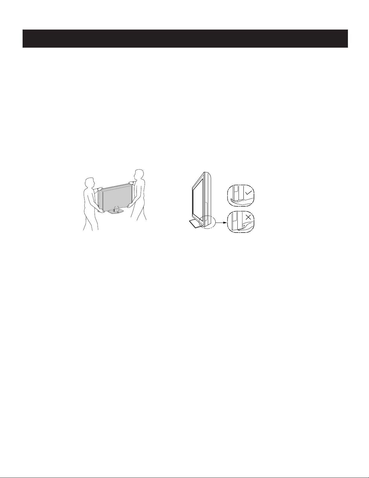
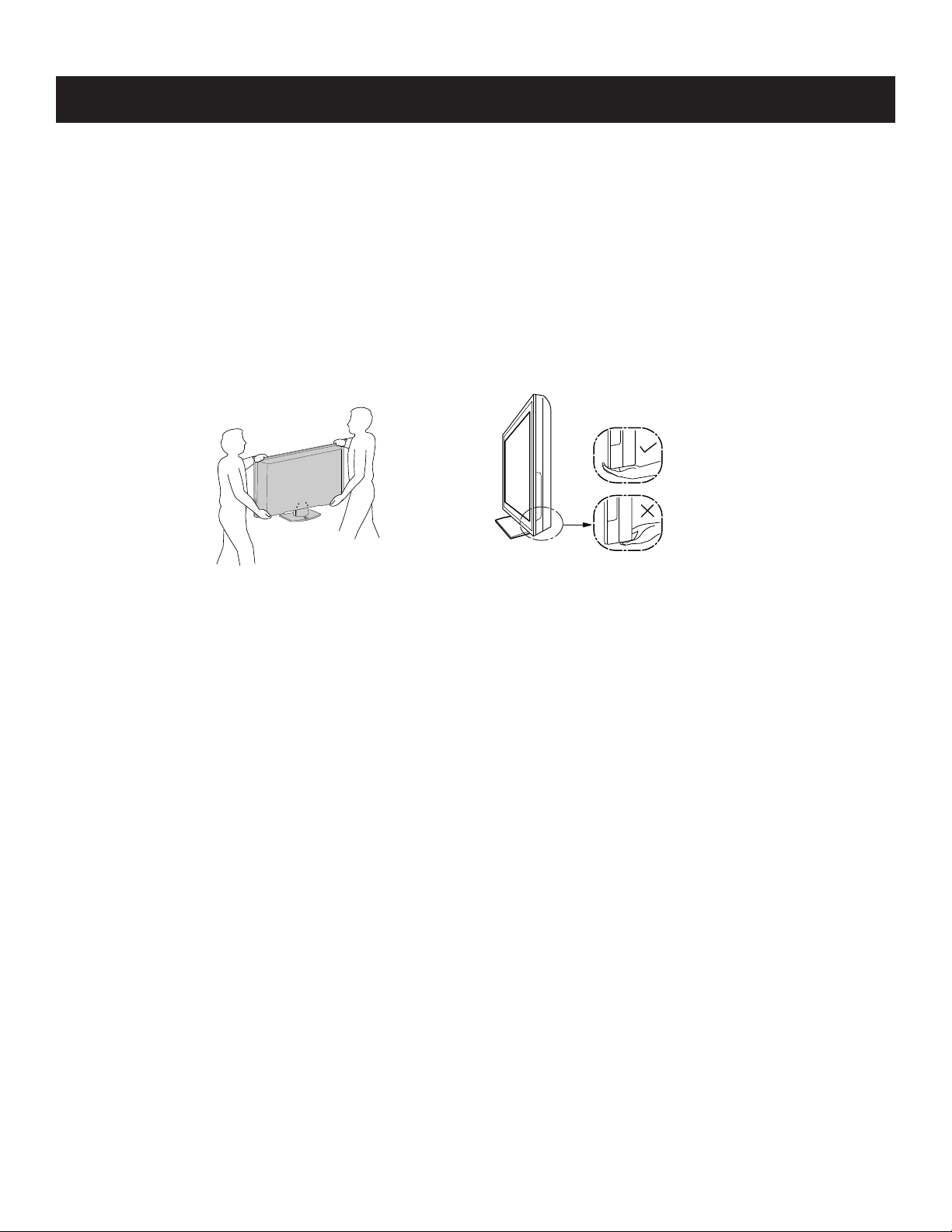
CARRYING THE TV
Be sure to follow these guidelines to protect your property and avoid causing serious injury.
• Carry the TV with an adequqate number of people; larger size TVs require two or more people.
• Correct hand placement while carrying the TV is very important for safety and to avoid damages.
WARNING!!
An isolation transformer should be used during any service to avoid possible shock hazard, because of live chassis. The chassis of this receiver is
directly connected to the ac power line.
! SAFETY-RELATED COMPONENT WARNING!!
Components identifi ed by shading and ! mark on the schematic diagrams, exploded views, and in the parts list are critical for safe operation. Replace
these components with Sony parts whose part numbers appear as shown in this manual or in supplements published by Sony. Circuit adjustments that
are critical for safe operation are identifi ed in this manual. Follow these procedures whenever critical components are replaced or improper operation is
suspected.
KDL-52S5100/52V5100
6
Page 7
KDL-52S5100/52V5100
WARNINGS AND CAUTIONS - FRENCH
ATTENTION!!
Ces instructions de service sont à l’usage du personnel de service qualifi é seulement. Pour prévenir le risque de choc électrique, ne pas faire
l’entretien autre que celui contenu dans le Mode d’emploi à moins que vous soyez qualifi é faire ainsi.
POUR TRANSPORTER LE TÉLÉVISEUR
Tenez compte de ce qui suit pendant l’installation du téléviseur :
• Débranchez tous les câbles avant de transporter le téléviseur.
• Transportez le téléviseur avec le nombre de personnes approprié ; un téléviseur de grande
taille doit être transporté par au moins deux personnes.
• Lors du transport du téléviseur, l’emplacement des mains est très important pour votre
sécurité, ainsi que pour éviter de causer des dommages.
ALERTE!!
Afi n d’eviter tout risque d’electrocution provenant d’un chássis sous tension, un transformateur d’isolement doit etre utilisé lors de tout dépannage. Le
chássis de ce récepteur est directement raccordé à l’alimentation du secteur.
! ATTENTION AUX COMPOSANTS RELATIFS A LA SECURITE!!
Les composants identifi es par une trame et par une marque ! sur les schemas de principe, les vues explosees et les listes de pieces sont d’une
importance critique pour la securite du fonctionnement. Ne les remplacer que par des composants Sony dont le numero de piece est indique dans le
present manuel ou dans des supplements publies par Sony. Les reglages de circuit dont l’importance est critique pour la securite du fonctionnement
sont identifi es dans le present manuel. Suivre ces procedures lors de chaque remplacement de composants critiques, ou lorsqu’un mauvais
fonctionnement suspecte.
KDL-52S5100/52V5100
7
Page 8
SAFETY-RELATED COMPONENT WARNING
KDL-52S5100/52V5100
There are critical components used in LCD color TVs that are important for safety. These components are identifi ed with shading and
mark on the schematic diagrams and the electrical parts list. It is essential that these critical parts be replaced only with the part number
specifi ed in the electrical parts list to prevent electric shock, fi re, or other hazard.
NOTE: Do not modify the original design without obtaining written permission from the manufacturer or you will void the original parts and
labor guarantee.
!
USE CAUTION WHEN HANDLING THE LCD PANEL
When repairing the LCD panel, be sure you are grounded by using a wrist band.
When installing the LCD panel on a wall, the LCD panel must be secured using the 4 mounting holes on the rear cover.
To avoid damaging the LCD panel:
do not press on the panel or frame edge to avoid the risk of electric shock.
do not scratch or press on the panel with any sharp objects.
do not leave the module in high temperatures or in areas of high humidity for an extended period of time.
do not expose the LCD panel to direct sunlight.
avoid contact with water. It may cause a short circuit within the module.
disconnect the AC adapter when replacing the backlight (CCFL) or inverter circuit.
(High voltage occurs at the inverter circuit at 650Vrms.)
always clean the LCD panel with a soft cloth material.
use care when handling the wires or connectors of the inverter circuit. Damaging the wires may cause a short.
protect the panel from ESD to avoid damaging the electronic circuit (C-MOS).
LEAKAGE CURRENT HOT CHECK CIRCUIT
KDL-52S5100/52V5100
8
Page 9
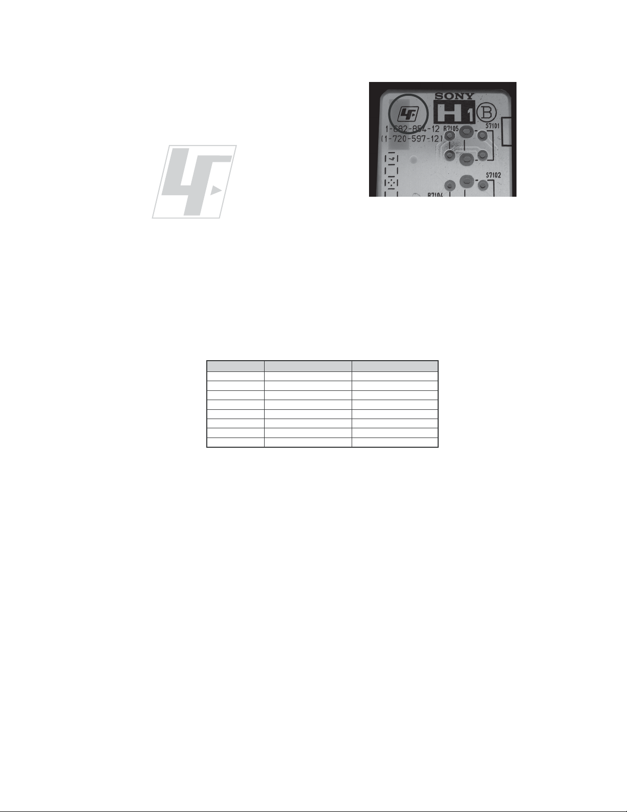
The circuit boards used in these models have been processed using
Lead Free Solder. The boards are identified by the LF logo located
close to the board designation e.g. H1 etc [ see example ]. The
servicing of these boards requires special precautions to be taken as
outlined below.
KDL-52S5100/52V5100
example 1
It is strongly recommended to use Lead Free Solder material in order to guarantee optimal quality of new solder joints.
Lead Free Solder is available under the following part numbers :
rebmuntraP retemaiD skrameR
91-500-046-7mm3.0gK52.0
02-500-046-7mm4.0gK05.0
12-500-046-7mm5.0gK05.0
22-500-046-7mm6.0gK52.0
32-500-046-7mm8.0gK00.1
42-500-046-7mm0.1gK00.1
52-500-046-7mm2.1gK00.1
62-500-046-7mm6.1gK00.1
Due to the higher melting point of Lead Free Solder the soldering iron tip temperature needs to be set to 370 degrees centigrade.
This requires soldering equipment capable of accurate temperature control coupled with a good heat recovery characteristics.
For more information on the use of Lead Free Solder, please refer to
http://www.sony-training.com
KDL-52S5100/52V5100
9
Page 10
SAFETY CHECK-OUT
KDL-52S5100/52V5100
After correcting the original service problem, perform the following
safety checks before releasing the set to the customer:
1. Check the area of your repair for unsoldered or poorly soldered
connections. Check the entire board surface for solder splashes and
bridges.
2. Check the interboard wiring to ensure that no wires are “pinched” or
touching high-wattage resistors.
3. Check that all control knobs, shields, covers, ground straps, and
mounting hardware have been replaced. Be absolutely certain that
you have replaced all the insulators.
4. Look for unauthorized replacement parts, particularly transistors,
that were installed during a previous repair. Point them out to the
customer and recommend their replacement.
5. Look for parts which, though functioning, show obvious signs of
deterioration. Point them out to the customer and recommend their
replacement.
6. Check the line cords for cracks and abrasion. Recommend the
replacement of any such line cord to the customer.
7. Check the antenna terminals, metal trim, “metallized” knobs, screws,
and all other exposed metal parts for AC leakage. Check leakage as
described below.
The AC leakage from any exposed metal part to earth ground and
from all exposed metal parts to any exposed metal part having a
return to chassis, must not exceed 0.5 mA (500 microamperes).
Leakage current can be measured by any one of three methods.
1. A commercial leakage tester, such as the Simpson 229 or RCA
WT-540A. Follow the manufacturers’ instructions to use these
instructions.
2. A battery-operated AC milliampmeter. The Data Precision 245
digital multimeter is suitable for this job.
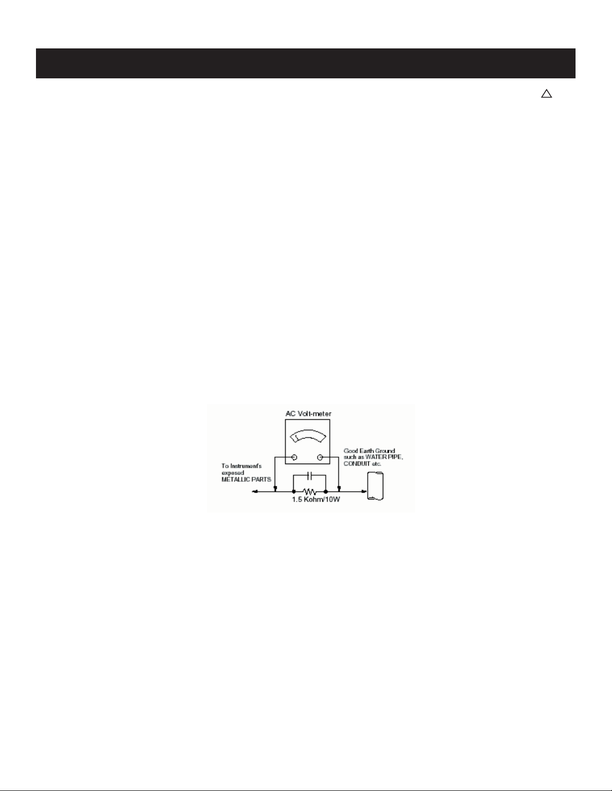
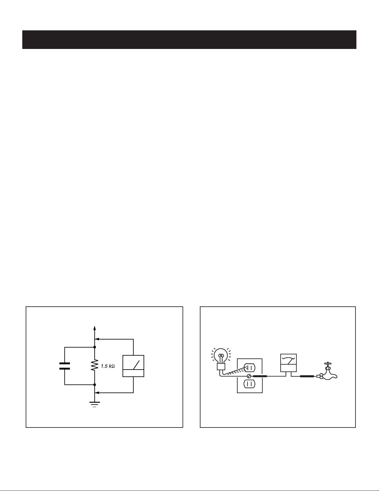
3. Measuring the voltage drop across a resistor by means of a VOM
or battery-operated AC voltmeter. The “limit” indication is 0.75
V, so analog meters must have an accurate low voltage scale.
The Simpson’s 250 and Sanwa SH-63TRD are examples of
passive VOMs that are suitable. Nearly all battery-operated digital
multimeters that have a 2 VAC range are suitable (see Figure A).
How to Find a Good Earth Ground
A cold-water pipe is a guaranteed earth ground; the cover-plate
retaining screw on most AC outlet boxes is also at earth ground. If the
retaining screw is to be used as your earth ground, verify that it is at
ground by measuring the resistance between it and a cold-water pipe
with an ohmmeter. The reading should be zero ohms.
If a cold-water pipe is not accessible, connect a 60- to 100-watt
trouble- light (not a neon lamp) between the hot side of the receptacle
and the retaining screw. Try both slots, if necessary, to locate the hot
side on the line; the lamp should light at normal brilliance if the screw
is at ground potential (see Figure B).
Leakage Test
0.15 μF
Figure A. Using an AC voltmeter to check AC leakage. Figure B. Checking for earth ground.
To Exposed Metal
Parts on Set
Earth Ground
AC
Voltmeter
(0.75V)
Trouble Light
AC Outlet Box
Ohmmeter
Cold-water Pipe
KDL-52S5100/52V5100
10
Page 11
KDL-52S5100/52V5100
SELF-DIAGNOSTIC FUNCTION
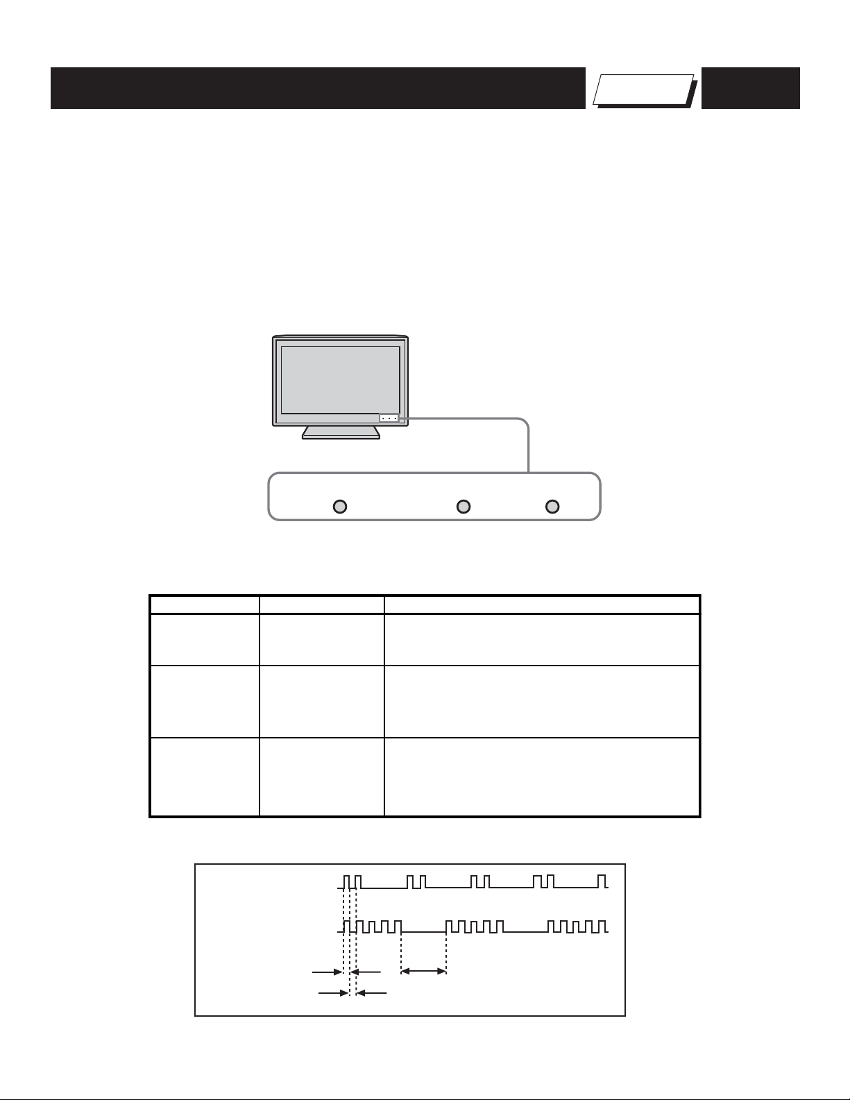
The units in this manual contain a self-diagnostic function. If an error occurs, the STANDBY LED indicator will automatically begin to fl ash. The number
of times the LED fl ashes translates to a probable source of the problem. A defi nition of the STANDBY LED fl ash indicators is listed in the instruction
manual for the user’s knowledge and reference. If an error symptom cannot be reproduced, the Remote Commander can be used to review the failure
occurrence data stored in memory to reveal past problems and how often these problems occur.
1. Diagnostic Test Indicators
When an error occurs, the STANDBY LED indicator will fl ash a set number of times to indicate the possible cause of the problem. If there is more than
one error, the indicator will identify the fi rst of the problem areas.
LED Indicators
PIC OFF / TIMER
STANDBY
POWER
Self Diagnosis
Supported model
Description of LED Indictors
LED LED Type Description
POWER LED
STANDBY LED
PIC OFF/
TIMER
LED
Green LED
Red LED
Green or Orange
LED
2 times
5 times
LED ON 0.3 sec.
LED OFF 0.3 sec.
* Lights up in green when the TV set is turned on.
* Lights up in red when TV is in PC standby mode.
* If LED blinks continuously, this may indicate
that the TV needs servicing.
* Lights up in green when Picture Off is activated.
* Lights up in orange when the timer is set.
When timer is set, this LED remains lit even
when the TV is turned off.
LED OFF
3 sec.
KDL-52S5100/52V5100
11
Page 12
LED Indicators
p
s
KDL-52S5100/52V5100
Diagnostic Item
Descri
tion
Main Power 2 times
DC Alert1 3 times
TCON Error 4 times LCD Panel
HDMI 5 times BM3 (Main) Board
Backlight 6 times LCD Panel
Temp 7 times BM3 (Main) Board
HFR Error 8 times LCD Panel
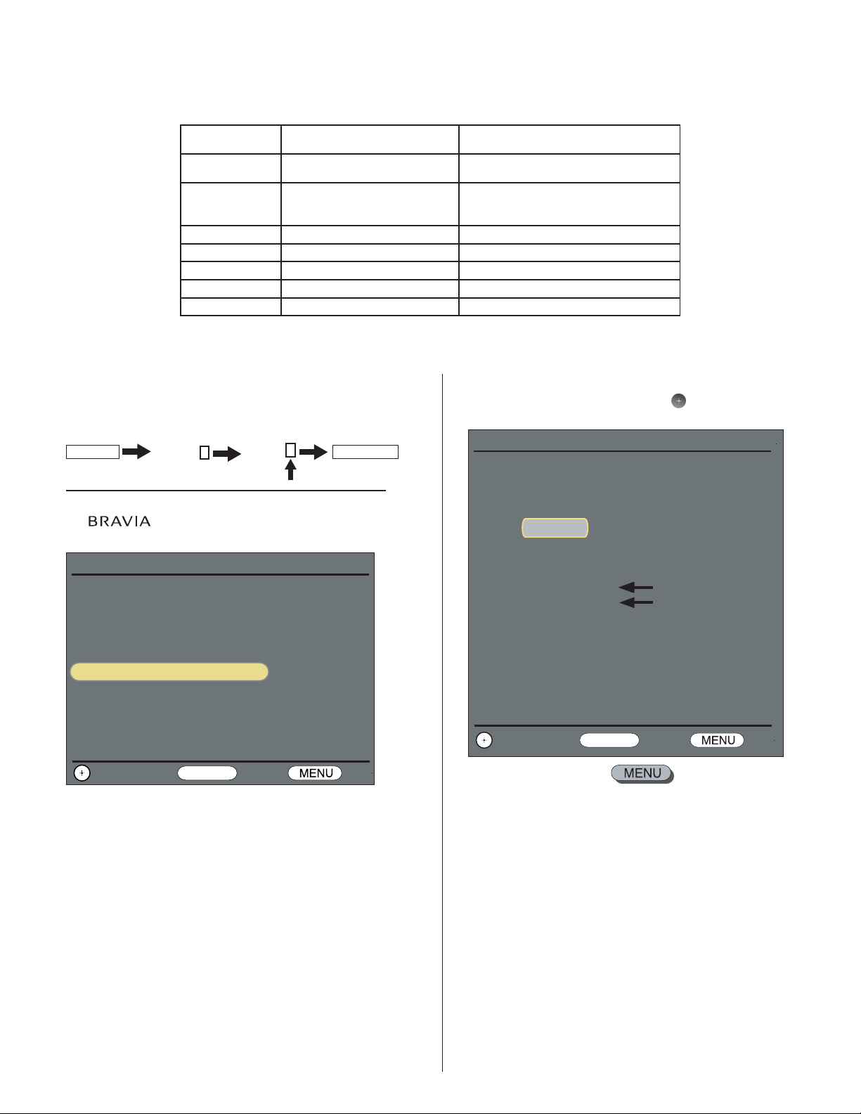
Viewing the Self Check Diagnostic List
1. TV must be in standby mode. (Power off).
2. Press the following buttons on the Remote Commander within a second
of each other:
DISPLAY
The Self Check list displays.
NOTE: This is the same as accessing Service Adjustments.
The
displays.
Channel 5 Volume +
logo displays momentarily, then the Service Mode list
Number of times
STANDBY lamp flashe
TV POWER
.
3. To display the Self Diagnostic list, press
Service/ADC Auto Calibration
Version: ER2.6-C121 DTT: S255.P033.S077
Model: 52V5100
Serial : 8000016
Power on Time: 00000H
Diagnostic and Serial Update
ADC Auto Calibration
Clone User Setting
Direct Log to USB
Factory Default
Change Back Exit
RETURN
4. To exit Service Mode, press .
Possible Location
Power Supply Board
G5N Board
BM3 (Main) Board
Power Supply Board
G5N Board
.
Service Mode/Product Information
Version: ER2.6-C121 DTT: S255.P033.S077
Model: 52V5100
Power on Time: 00000H
Serial :
Diagnostic Information
2-MAIN POWER: 1
3-DC ALERT1: 0
8000016
1 indicates an error was detected
0 indicates no error was detected
4-TCON: 0
5-HDMI:
0
6-Backlight: 0
7-TEMP: 0
8-HFR: 0
101-WDT: 0
Change Back Exit
RETURN
KDL-52S5100/52V5100
12
Page 13
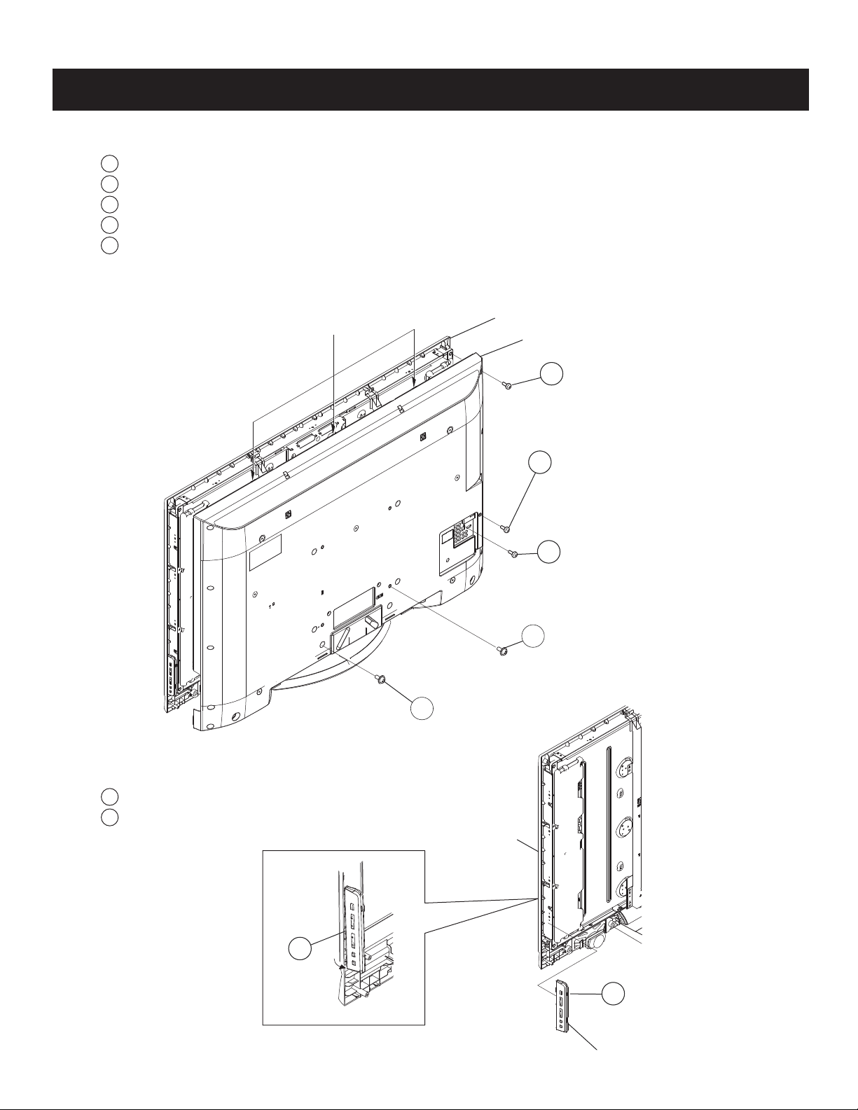
1-1. REAR COVER REMOVAL
1
Remove 20 screws from Rear Cover
2
Remove 1 screw from Side Jack position
3
Remove 1 screw from Terminal position
4
Remove 4 screws from Rear Cover
5
Remove 4 screws from Rear Cover
NOTE: The Rear Cover is attached to the Bezel Assembly with three small tabs.
Use caution when removing the Rear Cover not to damage these tabs.
SECTION 1: DISASSEMBLY
Bezel
Tab Inserts
Rear Cover
1
Screw,
+BVTP2 4X16
KDL-52S5100/52V5100
5
Screw,
+PSW M5X16
1-2. SWITCH UNIT REMOVAL (CONTAINS HSW3 BOARD)
1
Lift up the bottom of Switch Unit from Bezel and unhook from Bezel
2
Disconnect 1 connector from HW3 Board
Bezel
2
Screw,
+BVTP 3X12 TYPE2 IT-3
Screw,
3
+BVTP 3X12 TYPE2 IT-3
4
Screw,
+PSW M4X12
KDL-52S5100/52V5100
1
2
Switch Unit (Contains HSW3 Board)
13
Page 14
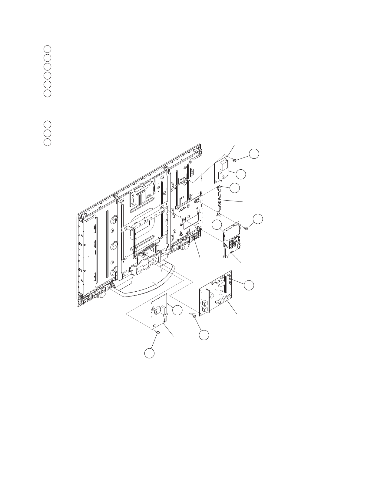
1-3. BM3 BOARD, G5N BOARD, D5N BOARD, AND D6N BOARD REMOVAL
1
Disconnect 3 connectors from D6N Board
2
Remove 4 screws from D6N Board
3
Unhook Side Jack from Main Bracket
4
Disconnect 5 connectors from BM3 Board
5
Remove 9 screws from BM3 Board
6
Disconnect 6 connectors from G5N Board
(KDL-52S5100 Only)
Disconnect 7 connectors from G5N Board
(KDL-52V5100 Only)
7
Remove 6 screws from G5N Board
8
Disconnect 5 connectors from D5N Board
9
Remove 4 screws from D5N Board
D6N Board
2 Screw,
+BVST 3X6
1
3
KDL-52S5100/52V5100
D5N Board
9 Screw,
+BVST 3X6
Main Bracket
8
4
7 Screw,
+BVST 3X6
Side Jack Cover
5 Screw,
+BVST 3X6
BM3 Board
6
G5N Board
KDL-52S5100/52V5100
14
Page 15
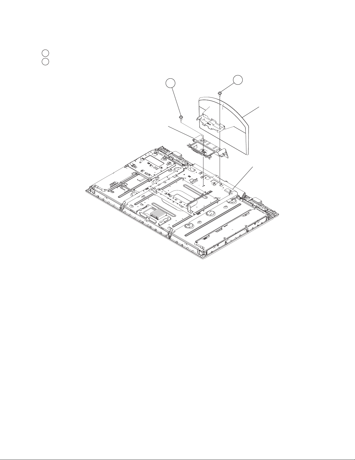
1-4. TABLE-TOP STAND ASSEMBLY AND UNDER COVER REMOVAL
1
Remove 4 screws Table-Top Stand Assembly
2
Remove 1 screw from Under Cover
KDL-52S5100/52V5100
Under Cover
2 Screw,
+PSW M4X12
1 Screw,
+PSW M5X12
Ta bl e -To p
Stand Assembly
Bottom Frame
KDL-52S5100/52V5100
15
Page 16
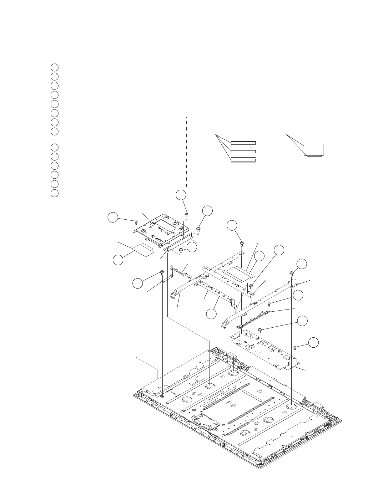
1-5. BRACKETS AND SPINE REMOVAL
1-5-1. KDL-52S5100
1
Remove 2 screws from D Frame Support and D Frame
2
Gently peel off Insulation Sheet (D6) from LCD panel and Main Frame
3
Remove 1 screw from Main Frame and Bezel
4
Remove 2 screws from Main Frame and Main Frame Support
5
Remove 1 screw from bottom of Main Frame Support
6
Remove 1 screw from top of Main Frame Support
7
Unhook VESA Frame from Center Frame
8
Gently peel off Insulation Sheet (G5) from
LCD panel and Center Frame
9
Remove 2 screws from Center Frame
10
Remove 1 screw from G Frame
11
Remove 4 screws from Spine(L)
12
Remove 4 screws from Spine(R)
13
Remove 1 screw from Bottom Frame
14
Remove 3 screws from Bottom Frame
Main Frame
+BVTP 3X12
TYPE2 IT-3
Insulation
Sheet (D6)
3Screw,
2
+PSW M3X5
Main Frame
Support
1Screw,
D6 Frame
Support
4 Screw,
+BVST 3X8
D Frame
VESA Frame
Spine (L)
Insulating Sheet Detail
Double Sided Tape
6 Screw,
+PSW M5X8
11 Screw,
+PSW M5X8
Screw,
5
+PSW M4X8
7
KDL-52S5100/52V5100
Double Sided Tape
G5N D6N
KDL-52S5100 Only
Insulation Sheet (G5N)
9 Screw,
8
Center
Frame
+PSW M5X8
12 Screw,
+PSW M5X8
Spine (R)
10 Screw,
+BVST 3X6
G Frame
13 Screw,
+PSW M5X8
KDL-52S5100/52V5100
14 Screw,
+BVTP2 4X16
Bottom Frame
16
Page 17
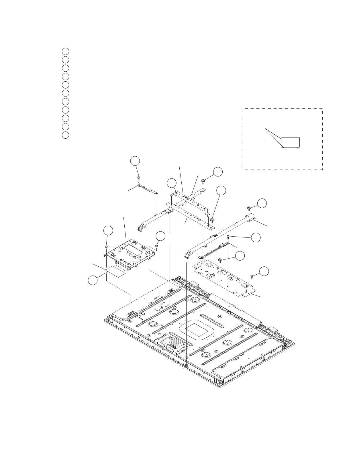
1-5-2. KDL-52V5100
1
Remove 1 screw from D Frame
2
Gently peel off Insulation Sheet (D6) from LCD panel and Main Frame
3
Remove 1 screw from Main Frame and Bezel
4
Remove 2 screws from Main Frame
5
Unhook VESA Frame from Center Frame
6
Remove 2 screws from Center Frame
7
Remove 1 screw from G Frame
8
Remove 4 screws from Spine(L)
9
Remove 4 screws from Spine(R)
10
Remove 3 screws from Bottom Frame
11
Remove 1 screw from Bottom Frame
KDL-52S5100/52V5100
Insulating Sheet Detail
Double Sided Tape
Screw,
+BVTP 3X12
TYPE2 IT-3
Insulation
Sheet (D6)
2
D Frame
Main Frame
3
1 Screw,
+BVST 3X6
VESA Frame
5
Center Frame
4 Screw,
+BVST 3X6
Spine (L)
D6
KDL-52V5100 Only
8 Screw,
+PSW M5X8
6 Screw,
+PSW M5X8
9 Screw,
+PSW M5X8
Spine (R)
7 Screw,
+BVST 3X6
G Frame
11 Screw,
+PSW M5X8
10 Screw,
+BVTP2 4X16
Bottom Frame
KDL-52S5100/52V5100
17
Page 18
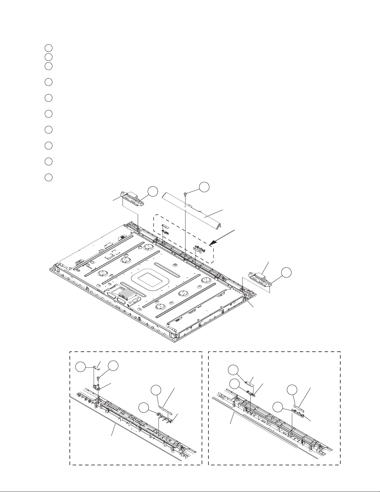
1-6. LOUDSPEAKER, UNDER BAR, IR GUIDE, AND LED GUIDE REMOVAL
1
Slide out both Speakers from Bezel
2
Remove 1 screw from Under Bar
3
Disconnect 1 connector from HSR Board and remove from IR Guide
(KDL-52S5100 Only)
4
Remove 1 screw from IR Guide from Bezel
(KDL-52S5100 Only)
5
Disconnect 1 connector from HLR1 Board and remove from LED Guide
(KDL-52S5100 Only)
6
Release hook and remove LED Guide from Bezel
(KDL-52S5100 Only)
7
Disconnect 1 connector from HSR Board and remove from IR Guide
(KDL-52V5100 Only)
8
Release hook and remove IR Guide from Bezel
(KDL-52V5100 Only)
9
Disconnect 1 connector from HLR4 Board and remove from LED Guide
(KDL-52V5100 Only)
10
Release hook and remove LED Guide from Bezel (KDL-52V5100 Only)
1
Speaker
2 Screw,
+BVTP2 4X16
Under Bar
KDL-52S5100/52V5100
DETAIL-A
HSR Board
3
4
Screw,
+BVTP 3X12
TYPE2 IT-3
IR Guide
HLR1 Board
5
DETAIL-A
7
HSR Board
8
Speaker
Bezel
IR Guide
1
HLR4 Board
9
KDL-52S5100 Only
KDL-52S5100/52V5100
Bezel
6
LED Guide
Bezel
KDL-52V5100 Only
10
LED Guide
18
Page 19
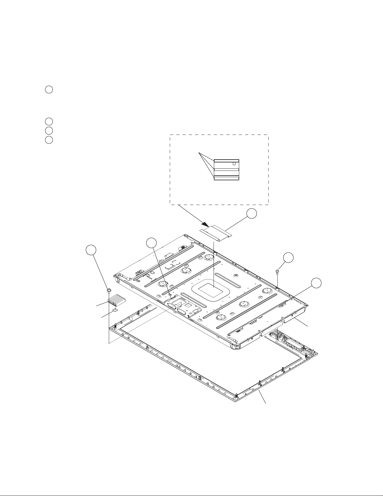
1-7. LCD PANEL REMOVAL
CAUTION: The Heat Sink and Radiation Sheet are not included in the KDL-52V5100 model LCD Panel.
When replacing the LCD Panel replacement, you must also replace the Radiation sheet. For part number information,
refer to the Exploded View section of this manual.
NOTE: Illustrations shown is KDL-52S5100 model.
1
Remove LVDS cable and holder from T-CON and LCD panel
(KDL-52S5100 Only)
Remove LVDS cable, 1 connector and holder from T-CON and LCD panel
(KDL-52V5100 Only)
2
Remove 2 screws and release LCD panel from Bezel
3
Disconnect 3 connectors from Inverter Boards
4
For KDL-52V5100 Only, remove 3 screws
and detach Heat Sink from LCD Panel
CAUTION: The LVDS cable can only be installed
one way
determine which side is attached to the TCON
and which side is attached to the BM3 Board.
. There is colored tape on the cable to
KDL-52S5100/52V5100
Insulating Sheet Detail
Double Sided Tape
4 Screw,
Heat Sink
Radiation
Sheet
+PSW M3X8
KDL-52S5100 Only
6
1
2 Screw,
+BVTP2 4X16
3
LCD Panel
1-7-1. CLEANING THE LCD PANEL
CAUTION: When cleaning the TV, be sure to unplug the power cord to avoid any chance of electric shock.
Clean the cabinet of the TV with a dry soft cloth.
Wipe the LCD screen gently with a soft cloth.
→
Stubborn stains may be removed with a cloth slightly moistened with a solution of mild soap and warm water.
→ If using a chemically pretreated cloth, please follow the instruction provided on the package.
→ Never use strong solvents such as a thinner, alcohol or benzine for cleaning.
→ Periodic vacuuming of the ventilation openings is recommended to ensure to proper ventilation.
KDL-52S5100/52V5100
Bezel
19
Page 20
KDL-52S5100 ONLY
KDL-52S5100/52V5100
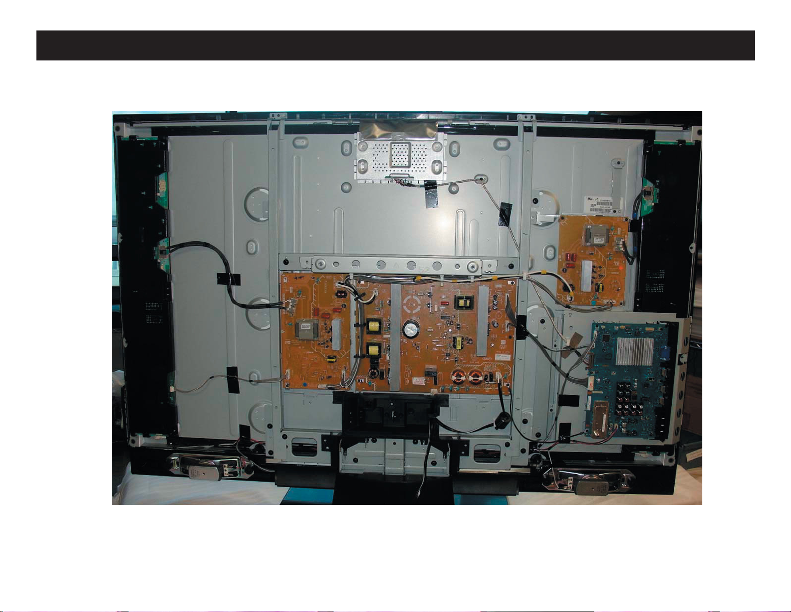
WIRE DRESSING
OVERALL ASSEMBL
Y
NOTE: THE TAPE COLOR ON THE LVDS CONNECTOR IS TO HELP DETERMINE THE CORRECT
KDL-52S5100/52V5100
CONNECTION PLACEMENT
20
Page 21
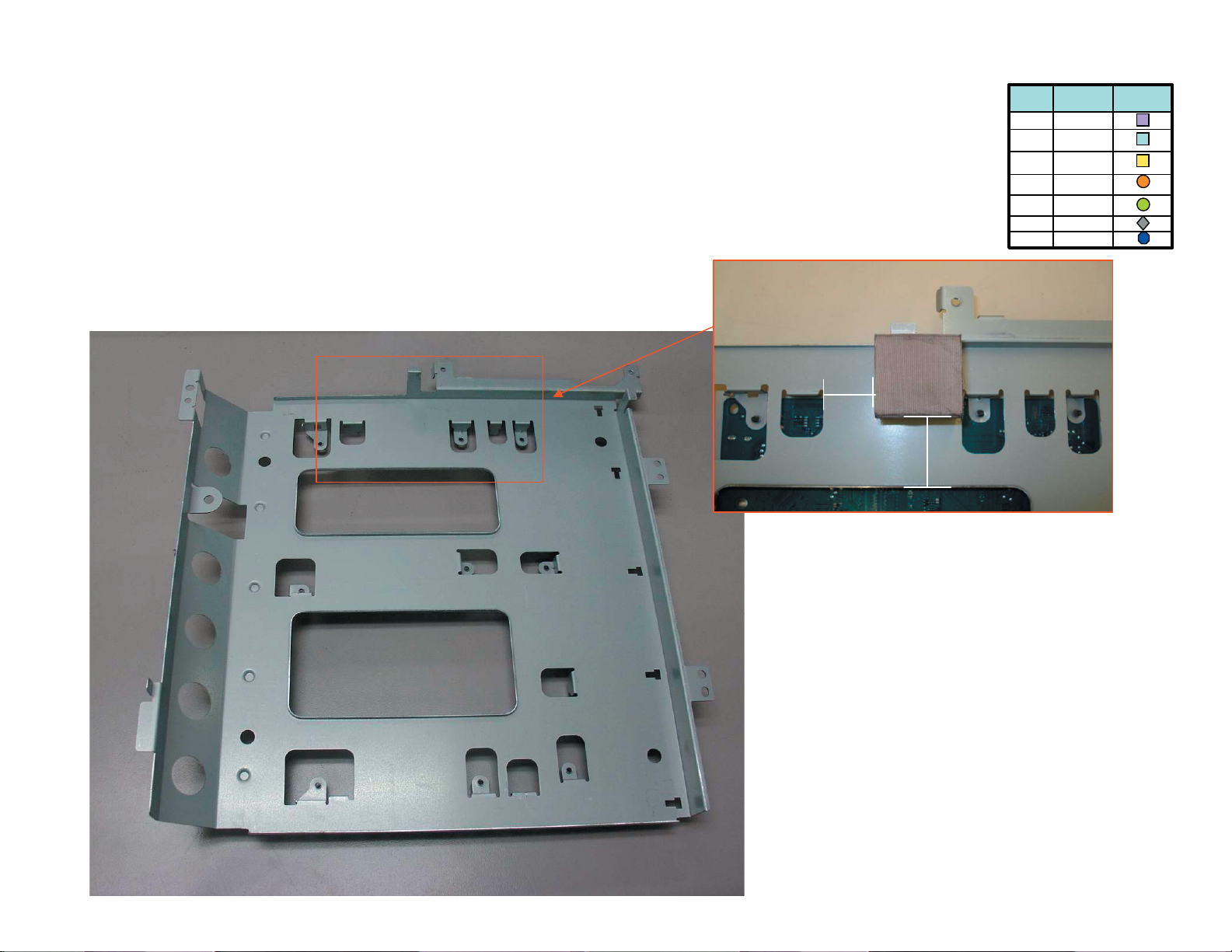
KDL-52S5100/52V5100
KDL-52S5100 ONLY
INSERT GASKET OVER THE BACK SIDE OF THE MAIN BRACKET
LEGEND
ytQ
4
2
1
11
noitpircseD
pmalc T
pmalc T
rof pmalC wercS
SDVL
epatbafoC1
)5198.oN(epaT
mm06xmm52
nolemiH2
teksaG1
ni lobmyS
gnisserd
tnemucod
72
mm
72
mm
KDL-52S5100/52V5100
21
Page 22
KDL-52S5100/52V5100
KDL-52S5100 ONLY
LVDS Connector
LEGEND
ytQ
4
2
1
11
2019NC/3MB ot noC T morf
ot etacidnI epat neerG
decalp eb ot tsrif eht eb lliw elbac SDVL ehT
noitpircseD
pmalc T
pmalc T
rof pmalC wercS
SDVL
epatbafoC1
)5198.oN(epaT
mm06xmm52
nolemiH2
teksaG1
ni lobmyS
gnisserd
tnemucod
edis noC T lenap
LVDS Connector
: noitacidnI
1
elbac SDVL tcennoC-
1
2
- neerG dna noC T ot DI epat
.)3MB( 2019NC ot edis rehtO
1 1
dna pmalC elbaC tresnI-
sepat
elbac
KDL-52S5100/52V5100
epaT ddA- 2 ,1 dna
1
tnioP noituaC
htiw demmaj parT diovA
egde yna hcuot ro latem
elbac eht sserts oN
elbac esool peeK
1
IME yb detseuqer epat
dna srotcennoc neewteb
1
2019NC 3MB
eht revo talf sepaT peeK
22
Page 23
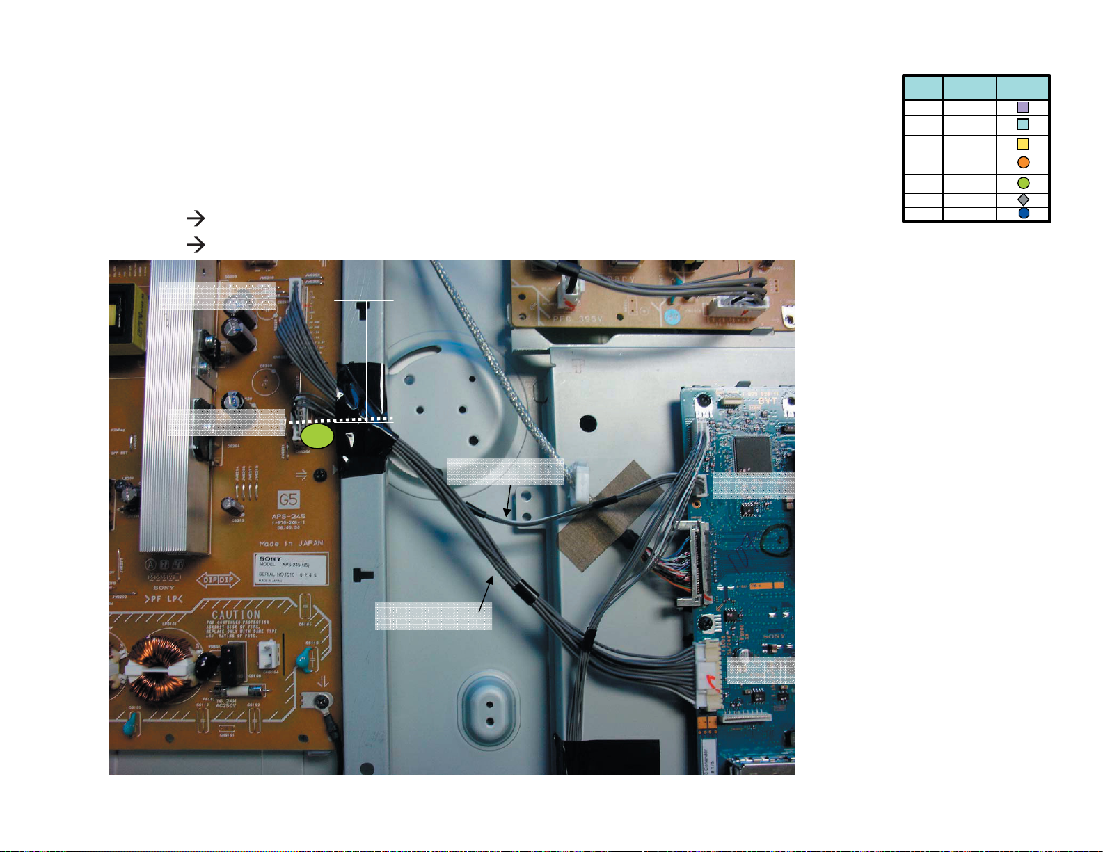
KDL-52S5100/52V5100
KDL-52S5100 ONLY
e 1lbaC 3001NC/3MB ot 2026NC/5G morf
e 2lbaC 4001NC/3MB ot 4026NC/5G morf
LEGEND
ytQ
4
2
1
11
noitpircseD
pmalc T
pmalc T
rof pmalC wercS
SDVL
epatbafoC1
)5198.oN(epaT
mm06xmm52
nolemiH2
teksaG1
ni lobmyS
gnisserd
tnemucod
2026NC/5G
selbac tcennoC
epat ddA2- 3 ,selbac htob revo
hsad eht ecnerefer yb gnikat
mm 57
4026NC/5G
senil
3
KDL-52S5100/52V5100
2
4001NC3MB
1
3001NC 3MB
23
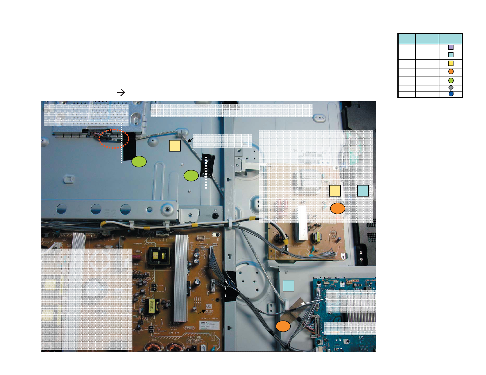
Page 24
KDL-52S5100/52V5100
KDL-52S5100 ONLY
e 1lbaC SRH ot 4003NC/3MB morftinu hctiwS dna 1LRH ,
e 2lbaC ot 002NC/3MB morf
LEGEND
ytQ
4
2
1
11
noitpircseD
pmalc T
pmalc T
rof pmalC wercS
SDVL
epatbafoC1
)5198.oN(epaT
mm06xmm52
nolemiH2
teksaG1
ni lobmyS
gnisserd
tnemucod
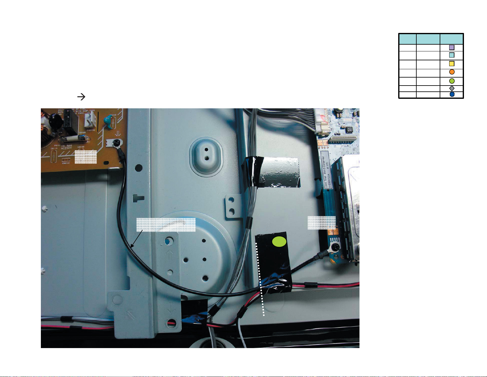
lenap retneC
ecnerefer
tinu hctiwS dna sdraob s’H ot elbca eht tcennoC1-
lanimret srekaeps thgir dna tfel ot elbac eht tcennoC2-
)ecnerefer sa enil dehsad ekat ( lenap fo retnec ta epat wolley etacol 2: ssenrah retnec oT-
erutcip ni wohs sa )sepat kcalB( sepat htob etacol 1: ssenrah retnec oT-
sredils txen eht ni wohs sa sepat ecalP-
KDL-52S5100/52V5100
01
1
2
4
6
8
5
24
Page 25
KDL-52S5100/52V5100
KDL-52S5100 ONLY
decalp gnieb
e 1lbaC SRH ot 4003NC/3MB morftinu hctiwS dna 1LRH ,
e 2lbaC srekaepS ot 002NC/3MB morf
eht sserts t’noD :tniop noituaC
si tinu hctiws eht elihw ,elbac
eht ot detcennoc eb llahs elbac ehT
tinu hctiws
LEGEND
ytQ
4
2
1
11
noitpircseD
pmalc T
pmalc T
rof pmalC wercS
SDVL
epatbafoC1
)5198.oN(epaT
mm06xmm52
nolemiH2
teksaG1
ni lobmyS
gnisserd
tnemucod
KDL-52S5100/52V5100
eht rednu ssorc llahs elbac ehT
egde lenap
2
6
tinu hctiwS
1
5
ot lanogaid ni epat ddA
egde lenap revoc
1RLH
25
Page 26
KDL-52S5100/52V5100
KDL-52S5100 ONLY
e 1lbaC
e 2lbaC srekaepS ot 002NC/3MB morf
1
LEGEND
ytQ
4
2
s’H ot 4003NC/3MB morf
4003NC/3MB
epat ddA- 7 revo lanogaid ni
1
11
noitpircseD
pmalc T
pmalc T
rof pmalC wercS
SDVL
epatbafoC1
)5198.oN(epaT
mm06xmm52
nolemiH2
teksaG1
ni lobmyS
gnisserd
tnemucod
tekcarb niam dna lenap eht
segde prahs
epat tresnI- 8 fo retnec eht ni
yb ekat ,lenap elcric eht
enil tod eht ecnerefer
epat ddA- 9 ecnerefer yb gnikat
enil hsad eht fo edis tfel eht
epat tresnI- 01 fo pot no
01
enil hsad ecnerefer
KDL-52S5100/52V5100
002NC/3MB
9
8
2
7
26
Page 27
KDL-52S5100/52V5100
KDL-52S5100 ONLY
e 1lbaC
5G
LEGEND
ytQ
4
2
1
11
noitpircseD
pmalc T
pmalc T
rof pmalC wercS
SDVL
epatbafoC1
)5198.oN(epaT
mm06xmm52
nolemiH2
teksaG1
ni lobmyS
gnisserd
tnemucod
draob 3MB fo wercs ot draob 5G fo wercS morf
KDL-52S5100/52V5100
1
3MB
9
27
Page 28
KDL-52S5100/52V5100
KDL-52S5100 ONLY
epaTnolemiH- 1 eht neewteb
LEGEND
ytQ
4
2
1
11
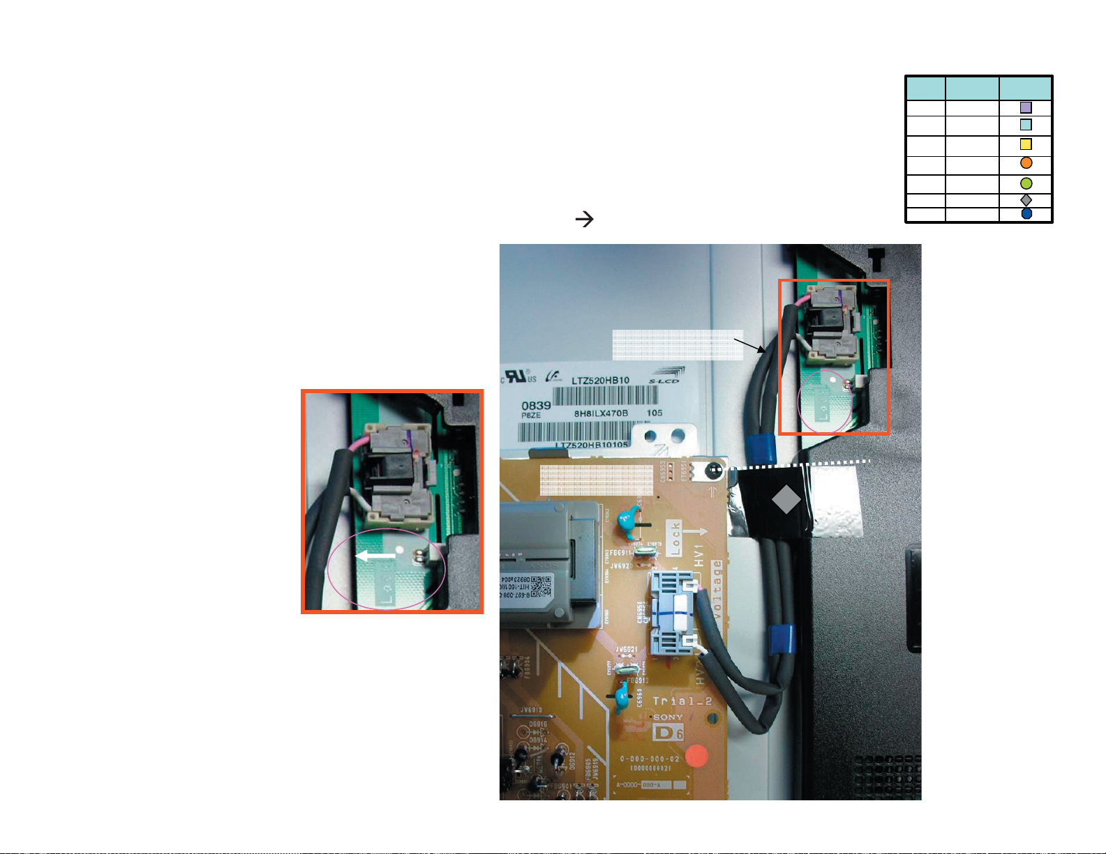
e 1lbaC
1596NC/6D ot recnalaB morf
noitpircseD
pmalc T
pmalc T
rof pmalC wercS
SDVL
epatbafoC1
)5198.oN(epaT
mm06xmm52
nolemiH2
teksaG1
ni lobmyS
gnisserd
tnemucod
yb gnikat ,epat selbac eulb owt
enil hsad eht ecnerefer
1
KDL-52S5100/52V5100
1596NC/6D
eht hsup dekcol oT
1
eht erew pac kcalb
stniop worra
28
Page 29
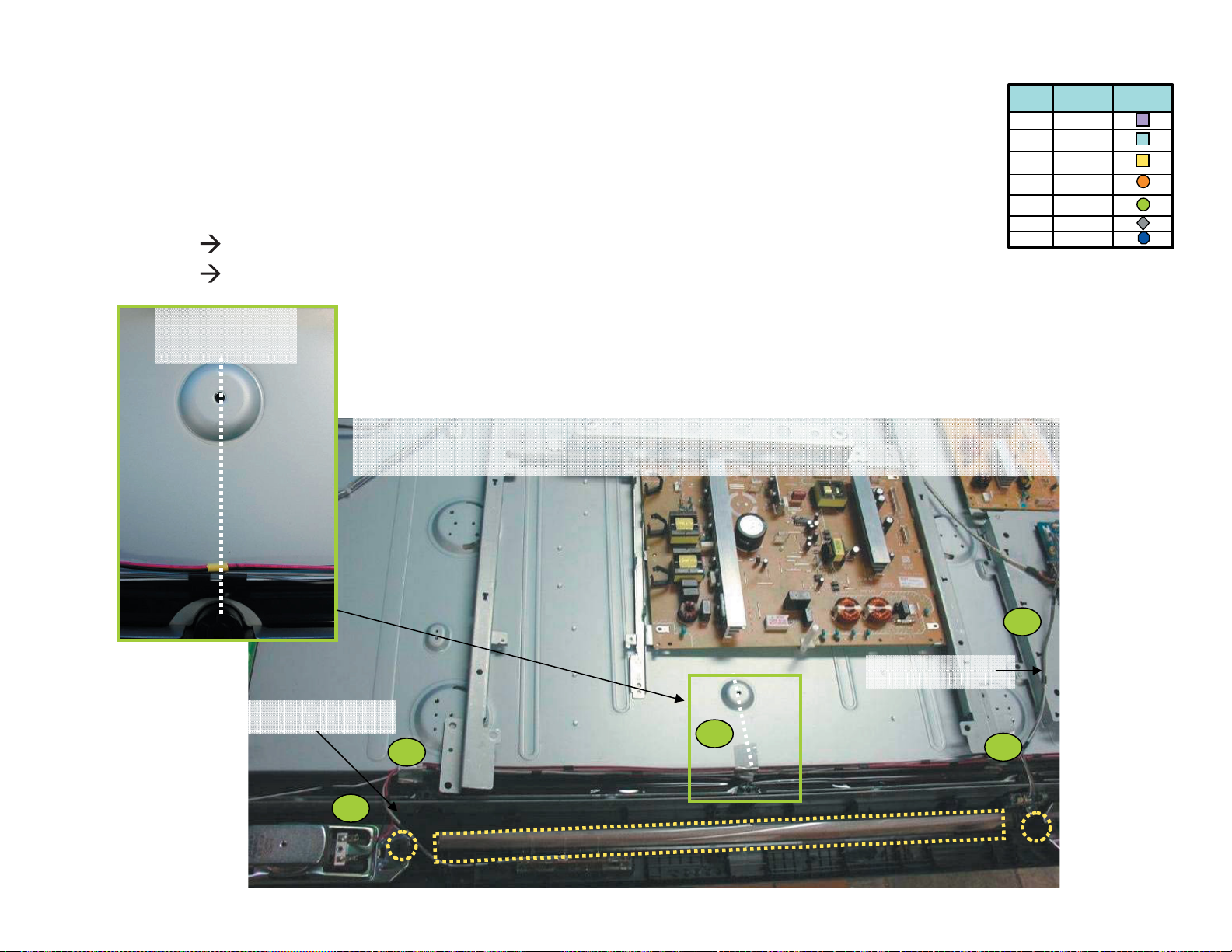
KDL-52S5100/52V5100
KDL-52S5100 ONLY
e 1lbaC 0076NC/5D ot recnalaB morf
e 2lbaC 0076NC/5D ot recnalaB morf
LEGEND
ytQ
4
2
1
11
noitpircseD
pmalc T
pmalc T
rof pmalC wercS
SDVL
epatbafoC1
)5198.oN(epaT
mm06xmm52
nolemiH2
teksaG1
ni lobmyS
gnisserd
tnemucod
epatnolemiH tresnI- 2 ni
recnalaB
2
yb gnikat yaw latnoziroh
.enil dettod eht ecnerefer
epat ddA- 11 mrof lacitrev ni
2
lenap eht ecnerefer yb gnikat
senil
esaelp dna S detrevni a ekaM epat eht
KDL-52S5100/52V5100
elddim eht ni
0076NC 5D
mm 021
1
11
recnalaB
11NC
1076NC 5D
29
Page 30
KDL-52S5100/52V5100
KDL-52S5100 ONLY
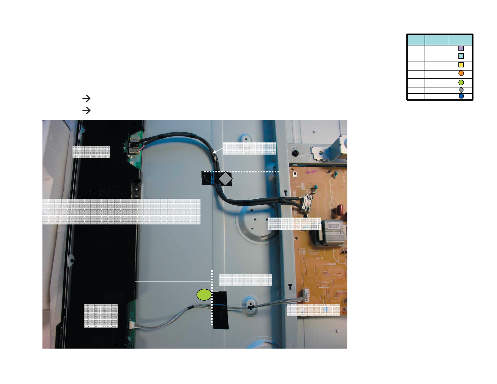
e 1lbaC
e 2lbaC 2076NC/5D ot 1026NC/5G morf
LEGEND
ytQ
4
2
1
0066NC/5D ot 1056NC/5G morf
11
noitpircseD
pmalc T
pmalc T
rof pmalC wercS
SDVL
epatbafoC1
)5198.oN(epaT
mm06xmm52
nolemiH2
teksaG1
ni lobmyS
gnisserd
tnemucod
1 2 3
-1
0066NC5D
morf spmalC
draob 5G
1056NC5G
KDL-52S5100/52V5100
:snoitacidnI
2076NC5D
umts
3 eht hguort ssap 2 elbaC
na draob 5G morf spmalc eht ni spmalc 3 eht d
emarf latem
um 1 elbaC ehT eno rednu ssap ts
draob 5G morf redloh pmalc
30
Page 31

KDL-52S5100/52V5100
KDL-52S5100 ONLY
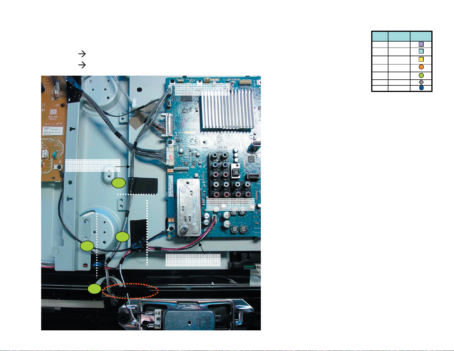
e 1lbaC
e 2lbaC 0596NC/6D ot 3076NC/5D morf
morf spmalC
draob 5G
LEGEND
ytQ
4
2
1
11
noitpircseD
pmalc T
pmalc T
rof pmalC wercS
SDVL
epatbafoC1
)5198.oN(epaT
mm06xmm52
nolemiH2
teksaG1
ni lobmyS
gnisserd
tnemucod
0096NC/6D ot 2056NC/5G morf
1
1
2 3
2056NC/5G
4
0096NC/6D
0596NC/6D
2
3076NC/5D
KDL-52S5100/52V5100
3 eht hguort ssap llahs e 2lbaC
na draob 5G morf spmalc eht ni spmalc 4 eht d
semarf latem
eht hguort ssap tsum e 1lbaC ehT
spmalc 2, 3 dna 4 semarf latem eht fo
31
Page 32

KDL-52S5100/52V5100
KDL-52S5100 ONLY
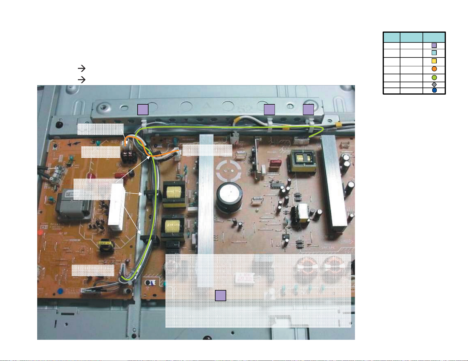
droc CA 5G
5G
AC Cord
LEGEND
ytQ
4
2
1
11
noitpircseD
pmalc T
pmalc T
rof pmalC wercS
SDVL
epatbafoC1
)5198.oN(epaT
mm06xmm52
nolemiH2
teksaG1
ni lobmyS
gnisserd
tnemucod
KDL-52S5100/52V5100
2
redloH CA
noitisop
mm 061
32
mm 511
Page 33

KDL-5VS5100 ONLY
OVERALL ASSEMBLY
KDL-52S5100/52V5100
NOTE: THE TAPE COLOR ON THE LVDS CONNECTOR IS TO HELP DETERMINE THE CORRECT
KDL-52S5100/52V5100
CONNECTION PLACEMENT
33
Page 34

KDL-52S5100/52V5100
KDL-52V5100 ONLY
GASKET ON MAIN BRACKET
1
LEGEND
ytQ
4
1
1
21
noitpircseD
pmalc T
pmalc T
rof pmalC wercS
SDVL
epatbafoC1
)5198.oN(epaT
mm06xmm52
nolemiH2
teksaG1
spilc lenaP2
epatbafoC1
teksaG1
gnisserd ni lobmyS
tnemucod
KDL-52S5100/52V5100
revo teksaG tresnI
tekcarb niam eht
yb gnikat edis kcab
hsad eht ecnerefer
enil
34
Page 35

KDL-52S5100/52V5100
KDL-52V5100 ONLY
LCD PANEL AND BRACKETS
1 2
1
LEGEND
ytQ
4
1
1
21
noitpircseD
pmalc T
pmalc T
rof pmalC wercS
SDVL
epatbafoC1
)5198.oN(epaT
mm06xmm52
nolemiH2
teksaG1
spilc lenaP2
epatbafoC1
teksaG1
gnisserd ni lobmyS
tnemucod
KDL-52S5100/52V5100
35
Page 36

KDL-52S5100/52V5100
KDL-52V5100 ONLY
epatbafoC draob 3MB fo renut no
LEGEND
ytQ
4
1
1
21
noitpircseD
pmalc T
pmalc T
rof pmalC wercS
SDVL
epatbafoC1
)5198.oN(epaT
mm06xmm52
nolemiH2
teksaG1
spilc lenaP2
epatbafoC1
teksaG1
gnisserd ni lobmyS
tnemucod
3MB
draob
KDL-52S5100/52V5100
bafoC
gnihcuot renut no epatbafoc ddA
epat
redloh tekcarb niam eht
1
redloh tekcarb niaM
36
Page 37

KDL-52S5100/52V5100
KDL-52V5100 ONLY
.)3MB(
1 1
.senil
LEGEND
ytQ
4
1
1
21
e 1lbaC 2019NC/3MB ot noC T morf
decalp eb ot tsrif eht eb lliw elbac SDVL ehT
,elbac SDVL tcennoC-
NOCT
etacidnI redloh SDVL edis NOCT lenap ot
noitpircseD
pmalc T
pmalc T
rof pmalC wercS
SDVL
epatbafoC1
)5198.oN(epaT
mm06xmm52
nolemiH2
teksaG1
spilc lenaP2
epatbafoC1
teksaG1
gnisserd ni lobmyS
tnemucod
NOCT ot DI redloh SDVL
2019NC ot edis rehto dna
1 pmalC elbaC tresnI-
elbaC SDVL
dna epaT ddA-
hsad eht ecnerefer yb gnikat
1
elbac
KDL-52S5100/52V5100
tnioP noituaC
htiw demmaj parT diovA
epaT
egde yna hcuot ro latem
elbac eht sserts Don’t
neewteb elbac esool peeK
sepat dna srotcennoc
eht revo talf sepaT peeK
1
pmalC 10-732-831-4
1
2019NC
bafoC
SDVL ylno gnidloh epat
37
Page 38

KDL-52S5100/52V5100
KDL-52V5100 ONLY
LEGEND
ytQ
4
1
1
21
e 1lbaC
1596NC/6D ot recnalaB morf
noitpircseD
pmalc T
pmalc T
rof pmalC wercS
SDVL
epatbafoC1
)5198.oN(epaT
mm06xmm52
nolemiH2
teksaG1
spilc lenaP2
epatbafoC1
teksaG1
gnisserd ni lobmyS
tnemucod
eht neewteb 1 epatnolemih ddA-
yb gnikat ,epat selbac eulb owt
1
enil hsad eht ecnerefer
KDL-52S5100/52V5100
1
1596NC 6D
epaT
elbac fo sezis htob kcoL
eht erew dekcol eht gnihsup
stniop worra
38
Page 39

KDL-52S5100/52V5100
KDL-52V5100 ONLY
selbac tcennoC-
htob revo 2 epat ddA-
eht ni swohs sa selbac
erutcip
e 1lbaC 3001NC/3MB ot 2026NC/5G morf
e 2lbaC 4001NC/3MB ot 4026NC/5G morf
2026NC
4026NC
LEGEND
ytQ
4
1
1
21
noitpircseD
pmalc T
pmalc T
rof pmalC wercS
SDVL
epatbafoC1
)5198.oN(epaT
mm06xmm52
nolemiH2
teksaG1
spilc lenaP2
epatbafoC1
teksaG1
gnisserd ni lobmyS
tnemucod
epaT
2
4001NC
KDL-52S5100/52V5100
2
3001NC
1
39
Page 40

KDL-52S5100/52V5100
KDL-52V5100 ONLY
e 1lbaC
e 2lbaCsrekaepS ot 002NC/3MB morf
ecnerefer
ecnerefer
LEGEND
ytQ
4
1
1
21
SRH ot 4003NC/3MB morftinu hctiwS dna 4LRH ,
lenap retneC
lenap retneC
noitpircseD
pmalc T
pmalc T
rof pmalC wercS
SDVL
epatbafoC1
)5198.oN(epaT
mm06xmm52
nolemiH2
teksaG1
spilc lenaP2
epatbafoC1
teksaG1
gnisserd ni lobmyS
tnemucod
KDL-52S5100/52V5100
tinu hctiwS dna sdraob s’H ot elbac 63-550-019-1 eht tcennoC-
lanimret srekaeps thgir dna tfel ot elbac 64-550-019-1 eht tcennoC-
dehsad ekat ( lenap fo retnec ta epat wolley etacol ,64 xiffus ssenrah retnec oT-
)ecnerefer sa enil
erutcip ni wohs sa )sepat kcalB( sepat htob etacol ,63 xiffus ssenrah retnec oT-
sredils txen eht ni wohs sa sepat rehto dna 3 epat ecalP-
1
epaT
tinu hctiwS
3
2
KPS R
SRH
KPS L
4RLH
40
Page 41

KDL-52S5100/52V5100
KDL-52V5100 ONLY
LEGEND
e 1lbaC SRH ot 4003NC/3MB morftinu hctiwS dna 4LRH ,
e 2lbaC srekaepS ot 002NC/3MB morf
ytQ
4
1
1
21
noitpircseD
pmalc T
pmalc T
rof pmalC wercS
SDVL
epatbafoC1
)5198.oN(epaT
mm06xmm52
nolemiH2
teksaG1
spilc lenaP2
epatbafoC1
teksaG1
gnisserd ni lobmyS
tnemucod
detcennoc eb llahs selbac ehT-
draob 4RLH dna tinu hctiws ot
yb gnikat 4 epat tresnI-
.enil tod eht ecnerefer
lanogaid ni 6 dna 5 epat ddA-
segde prahs lenap revoc ot
tinu hctiwS
4
5
KPS R
KDL-52S5100/52V5100
eht rednu ssorc llahs elbac ehT
egde lenap
2
4
6
5
4RLH
1
6
4RLH
41
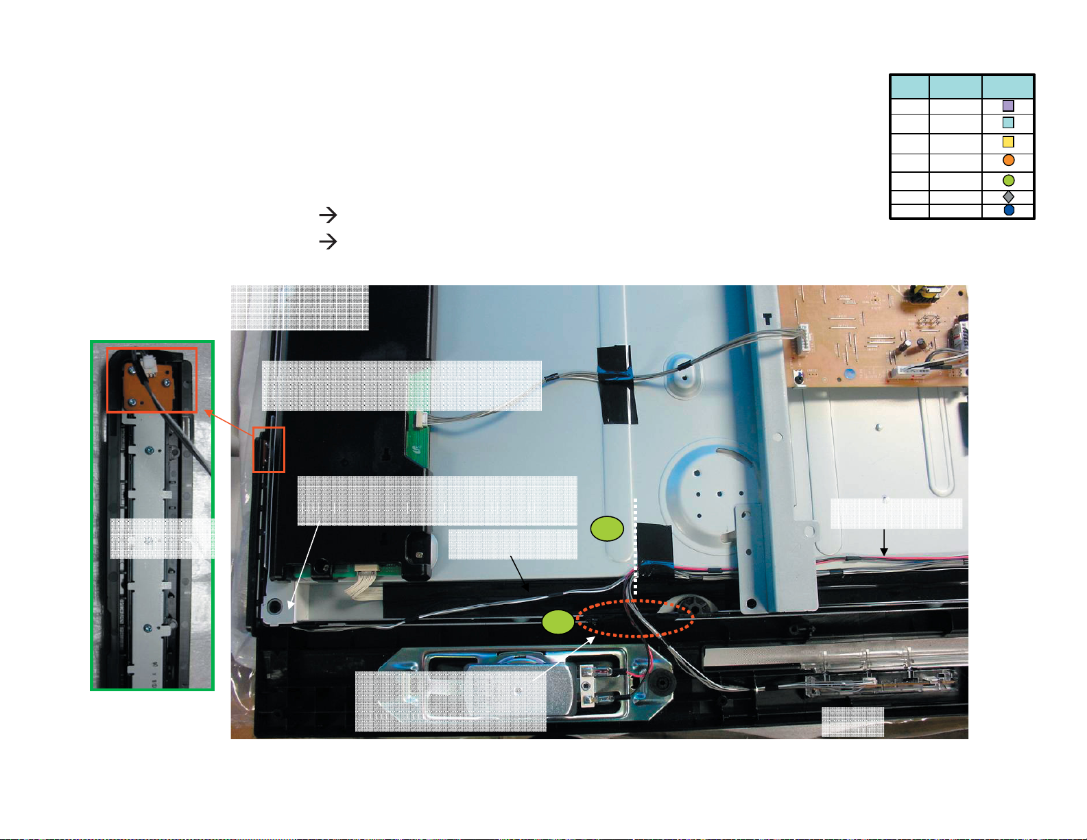
Page 42

KDL-52S5100/52V5100
KDL-52V5100 ONLY
e 1lbaC SRH ot 4003NC/3MB morftinu hctiwS dna 4LRH ,
e 2lbaC srekaepS ot 002NC/3MB morf
detcennoc eb llahs selbac ehT-
draob 4RLH dna tinu hctiws ot
lanogaid ni 8 dna 7 epat ddA-
segde prahs lenap revoc ot
1
LEGEND
ytQ
4
1
1
21
noitpircseD
pmalc T
pmalc T
rof pmalC wercS
SDVL
epatbafoC1
)5198.oN(epaT
mm06xmm52
nolemiH2
teksaG1
spilc lenaP2
epatbafoC1
teksaG1
gnisserd ni lobmyS
tnemucod
4003NC
3MB
9
7
KDL-52S5100/52V5100
yb gnikat 01 dna 9 epat tresnI-
.enil tod eht ecnerefer
01
0002NC
9
7
8
8
2
42
Page 43

KDL-52S5100/52V5100
KDL-52V5100 ONLY
senil
LEGEND
e 1lbaC 1076NC/5D ot11NC/recnalaB morf
e 2lbaC 0076NC/5D ot 10NC/recnalaB morf
ytQ
4
1
1
21
noitpircseD
pmalc T
pmalc T
rof pmalC wercS
SDVL
epatbafoC1
)5198.oN(epaT
mm06xmm52
nolemiH2
teksaG1
spilc lenaP2
epatbafoC1
teksaG1
gnisserd ni lobmyS
tnemucod
2
10NC
ni 2 epatnolemih ddA-
2
eht gnisaelp ,yaw latnoziroh
nwohs sa elbac
.erutcip eht ni
mrof lacitrev ni 11 epat ddA-
lenap eht ecnerefer yb gnikat
recnalaB
epaT
0076NC
KDL-52S5100/52V5100
5D
11
1076NC
11NC
1
epaT
43
Page 44

KDL-52S5100/52V5100
KDL-52V5100 ONLY
e 1lbaC 0066NC/5D ot 1056NC/5G morf
e 2lbaC 2076NC/5D ot 1026NC/5G morf
1
0066NC 1056NC
1 2 3
2
LEGEND
ytQ
4
1
1
21
noitpircseD
pmalc T
pmalc T
rof pmalC wercS
SDVL
epatbafoC1
)5198.oN(epaT
mm06xmm52
nolemiH2
teksaG1
spilc lenaP2
epatbafoC1
teksaG1
gnisserd ni lobmyS
tnemucod
1026NC
5D
2076NC
KDL-52S5100/52V5100
morf spmalC
5G
draob 5G
spmalc 3 eht hguort ssap llahs 2 elbaC
spmalc 3 eht dna draob 5G morf
emarf latem eht ni
eno rednu ssap tsum 1 elbaC
draob 5G morf redloh pmalc
44
Page 45

KDL-52S5100/52V5100
KDL-52V5100 ONLY
e 1lbaC
e 2lbaC0596NC/6D ot 3076NC/5D morf
1
5D
LEGEND
ytQ
4
1
1
21
0096NC/6D ot 2056NC/5G morf
noitpircseD
pmalc T
pmalc T
rof pmalC wercS
SDVL
epatbafoC1
)5198.oN(epaT
mm06xmm52
nolemiH2
teksaG1
spilc lenaP2
epatbafoC1
teksaG1
gnisserd ni lobmyS
tnemucod
6D
2
2
2056NC
3
1
4
0096NC 0596NC
morf spmalC
draob 5G
5G
3076NC
semarf
KDL-52S5100/52V5100
hguort ssap llahs 2 elbaCdna draob 5G morf spmalc 3 eht latem eht ni spmalc 4 eht
ssap tsum 1 elbaC 3 ,2 spmalc eht hguort semarf latem eht fo 4 dna
45
Page 46

KDL-52S5100/52V5100
KDL-52V5100 ONLY
elbac tcennoC-
21 epat tresnI-
LEGEND
ytQ
4
1
1
21
e 1lbaC
3026NC/5G ot 3NOC/NOCT morF
noitpircseD
pmalc T
pmalc T
rof pmalC wercS
SDVL
epatbafoC1
)5198.oN(epaT
mm06xmm52
nolemiH2
teksaG1
spilc lenaP2
epatbafoC1
teksaG1
gnisserd ni lobmyS
tnemucod
NOCT
3NOC
pmalC eht hguorht ssaP-
erutcip eht ni swohs sa 4
21
epaT
KDL-52S5100/52V5100
1
pmalC
4
3026NC
5G
46
Page 47

KDL-52S5100/52V5100
KDL-52V5100 ONLY
droc CA 5G
AC Cord
LEGEND
ytQ
4
1
1
21
noitpircseD
pmalc T
pmalc T
rof pmalC wercS
SDVL
epatbafoC1
)5198.oN(epaT
mm06xmm52
nolemiH2
teksaG1
spilc lenaP2
epatbafoC1
teksaG1
gnisserd ni lobmyS
tnemucod
5G
1
redloH CA
noitisop
KDL-52S5100/52V5100
pmalC
mm 071
47
Page 48

SECTION 2: SERVICE ADJUSTMENTS
KDL-52S5100/52V5100
2-1. VIEWING SERVICE ADJUSTMENT DATA
There are no adjustments necessary for these models. All data has
been set for optimal viewing for our customers. The following sections
are for informational purposes only.
2-2. ACCESSING SERVICE MODE
1. TV must be in standby mode. (Power off).
2. Press the following buttons on the Remote Commander within a
second of each other:
DISPLAY
Channel 5 Volume +
DISPLAY
CCDISPLAY POWER
WIDE INPUT
TV POWER
Onscreen cursor
and select button
TOOLS
POWER
.
The logo displays momentarily, then the Service Mode
list displays.
Service/ADC Auto Calibration
Version: ER2.6-C121 DTT: S255.P033.S077
Model: 52V5100
Serial : 8000016
Power on Time: 00000H
Diagnostic and Serial Update
ADC Auto Calibration
Clone User Setting
Direct Log to USB
Factory Default
Change Back Exit
RETURN
2-2-1. ENTERING THE SERIAL NUMBER
AFTER CHANGING THE MAIN BOARD
Use the following instructions to re-enter the Serial Number of the TV
after replacing the Main (BM3) Board.
1. After accessing service mode, press
list.
to display the Self Diagnostic
5
VOLUME+
RM-YD028
JUMP
Service Mode/Product Information
Version: ER2.6-C121 DTT: S255.P033.S077
Model: 52V5100
Power on Time: 00000H
Serial :
Diagnostic Information
2-MAIN POWER: 1
8000016
3-DC ALERT1: 0
4-TCON: 0
5-HDMI:
0
6-Backlight: 0
7-TEMP: 0
8-HFR: 0
101-WDT: 0
Change Back Exit
2. To change the serial number fi eld, press then using the number
keys on the remote enter the Serial Number of the TV.
3. To save the Serial Number, press
4. To exit Service Mode, press
RETURN
.
.
KDL-52S5100/52V5100
48
Page 49

2-2-2. RESETTING TO FACTORY DEFAULTS
1. After accessing service mode, press the button to highlight
Factory Default, then press
.
Service/ADC Auto Calibration
Version: ER2.6-C121 DTT: S255.P033.S077
Model: 52V5100
Serial : 8000016
Power on Time: 00000H
Diagnostic and Serial Update
ADC Auto Calibration
Clone User Setting
Direct Log to USB
Factory Default
KDL-52S5100/52V5100
Change Back Exit
RETURN
Service/ADC Auto Calibration
Version: ER2.6-C121 DTT: S255.P033.S077
Model: 52V5100
Serial : 8000016
Power on Time: 00000H
Diagnostic and Serial Update
ADC Auto Calibration
YES
NO
Clone User Setting
Direct Log to USB
Factory Default
2. To reset to Factory Defaults, press then follow the on-screen
3. After selecting the language preference the on-screen display
4. Continue following the on-screen instructions.
NOTE: All other Service Mode information listed, ADC Auto
Calibration, Clone User Setting, and Direct Log to USB will be
reviewed in the Training Manual for these models.
Change Back Exit
instructions.
indicates to “select the type of use for this TV.” Home must be
selected for optimal picture performance in the customers
home.
RETURN
KDL-52S5100/52V5100
49
Page 50

3-1. CIRCUIT BOARDS LOCATION
BM3
HSR
KDL-52S5100/52V5100
SECTION 3: DIAGRAMS
D6N
G5N
D5N
HLR1 (KDL-52S5100 ONLY)
HLR4 (KDL-52V5100 ONLY)
3-2. PRINTED WIRING BOARDS
AND SCHEMATIC DIAGRAMS INFORMATION
All capacitors are in μF unless otherwise noted. pF : μμF 50WV or
less are not indicated except for electrolytics and tantalums.
All electrolytics are in 50V unless otherwise specifi ed.
All resistors are in ohms. kΩ=1000Ω, MΩ=1000kΩ
Indication of resistance, which does not have one for rating
electrical power, is as follows: Pitch : 5mm
Rating electrical power :
1
/
W in resistance, 1/
4
W and 1/
10
W in chip resistance.
16
1
/
W
4
: nonfl ammable resistor
: fusible resistor
: internal component
: panel designation and adjustment for repair
: earth ground
: earth-chassis
All variable and adjustable resistors have characteristic curve B,
unless otherwise noted.
Readings are taken with a color-bar signal input.
Readings are taken with a 10MΩ digital multimeter.
Voltages are DC with respect to ground unless otherwise noted.
Voltage variations may be noted due to normal production
tolerances.
SWITCH UNIT
(HSW3)
All voltages are in V.
S : Measurement impossibility.
: B+line.
: B-line. (Actual measured value may be different).
: signal path. (RF)
Circled numbers are waveform references.
The components identifi ed by shading and ! symbol are critical for safety. Replace
only with part number specifi ed.
The symbol indicates a fast operating fuse and is displayed on the component
side of the board. Replace only with fuse of the same rating as marked.
!
Les composants identifi es per un trame et une marque
securite. Ne les remplacer que par une piece portant le numero specifi e.
Le symbole indique une fusible a action rapide. Doit etre remplace par une
fusible de meme yaleur, comme maque.
NOTE: The components identifi ed by a red outline and a mark contain confi dential
information. Specifi c instructions must be adhered to whenever these components
are repaired and/or replaced.
See Appendix A: Encryption Key Components in the back of this manual.
sont critiques pour la
KDL-52S5100/52V5100
50
Page 51

KDL-52S5100/52V5100
REFERENCE INFORMATION
RESISTOR
: RN METAL FILM
: RC SOLID
: FPRD NONFLAMMABLE CARBON
: FUSE NONFLAMMABLE FUSIBLE
: RW NONFLAMMABLE WIREWOUND
: RS NONFLAMMABLE METAL OXIDE
: RB NONFLAMMABLE CEMENT
: ADJUSTMENT RESISTOR
COIL
: LF-8L MICRO INDUCTOR
CAPACITOR
: TA TANTALUM
: PS STYROL
: PP POLYPROPYLENE
: PT MYLAR
: MPS METALIZED POLYESTER
: MPP METALIZED POLYPROPYLENE
: ALB BIPOLAR
: ALT HIGH TEMPERATURE
: ALR HIGH RIPPLE
Terminal name of semiconductors in silk screen
printed circuit ( )
Device Printed symbol Terminal name
Transistor
1
Transistor
2
3
Diode
4
Diode
Diode
5
Diode
6
Diode
7
8
Diode
Diode
9
Diode
0
Diode
!¡
Diode
!™
Transistor
!£
(FET)
Transistor
!¢
(FET)
Transistor
!?
(FET)
Transistor
!§
Transistor
!¶
Transistor
!•
Transistor
!ª
Transistor
@º
Transistor
@¡
Transistor
@™
Transistor
@£
Discrete semiconductot
–
(Chip semiconductors that are not actually used are included.)
*
Collector
Base
Collector
Base
Cathode
Cathode
Anode
Cathode
Anode
Common
Anode
Common
Anode Cathode
Common
Anode
Common
Anode Anode
Common
Cathode
Common
Cathode
Anode
Anode
Cathode
Drain
Drain
B1 E1
C2
B2 C1E2
B2 E2
C1
B1 C2
E1
B2 E2
C1
B1 C2E1
B2 E2
C1
B1 C2E1
E2
B1 E1
C2
(B2)
E1
B1
C1
(B2)
E1
E2
C2
Emitter
Emitter
Anode
(NC)
(NC)
Cathode
Anode
Cathode
Cathode
Cathode
Anode
Anode
Source
Gate
Source
Gate
Source
Drain
Gate
Emitter
Collector
Base
C1(B2)
E2
C2
B1
C1
Circuit
D
G
D
S
B1
B1
B1
B1
B1
B1
D
G
S
S
D
G
C1
E1
C1
E1
E1
C1
E2
C1
C1
G
S
C2
B2
E2
C2
B2
E2
E2
B2
C2
C2C1(B2)
E2
E2E1(B2)
C2
C2E1(B2)
C2
Ver.1.6
KDL-52S5100/52V5100
51
Page 52

3-3. BLOCK DIAGRAM
KDL-52S5100/52V5100
renuT
2RDD
bG1
FIS
SBVC
BSU
0.2
BSU
yHP 0.2
FI latigiD
IPLU
DNAN
hsalF
bM821
V
i
d
SBVC
3
V
i
laireS
hsalF
bM4
yeK
ecivreS
BSU
1.1
b TRAU
d TRAU
GIJ
TRAU
TSR
SCRIS
lortnoc tnorF
TSR
DEL
RI
neS noitoM
d
1
/
2
aTRAU
IPS
UCM
SAMIM
draoB SP
CP
342 noelliX
MVN
1 IMDH
CII
pmeT
2 IMDH
WS IMDH
5829IS
neS
SDVL
rewoP
ylppus
noCT
IVD oiduA
3 IMDH
4 IMDH
KDL-52S5100/52V5100
LENAP
MWP
CEDOC
FIDPS
lacitpO
TUO eniL
L
CII
PMA
CEC
PMA
R/L
R
Backlight/ Inv
52
Page 53

3-4. SCHEMATICS AND SUPPORTING INFORMATION
BM3 BOARD SCHEMATIC DIAGRAM (1 OF 9)
1 | 2 | 3 | 4 | 5 | 6 | 7 | 8 | 9 | 10 | 11 | 12 | 13 | 14 | 15 | 16 | 17 | 18 | 19 | 20 | 21 | 22 |
KDL-52S5100/52V5100
A
—
B
—
C
—
D
—
E
—
F
—
VideoInput2
S
34
12
V
L
R
TB1000
VD1042
CN1000
3P
BLK
V2_IN_Y
VD1006
GND
D3.3V
CHIP
1/16W
R1005
5%
3.3k
SVID_DET
VD1016
GND
VD1013
R1038
1/10W
RN-CP
C1032
1608
V2_IN_C
75
1
10V
X7R
Opt/Audio Output
AUDIO IN
DET_V1
GND
VD1012
VD1027
GND
GND
VD1014
GND
R1023
1/16W
CHIP
R1022
1/16W
CHIP
1M
R1028
10k
1M
1/16W
CHIP
R1029
1/16W
CHIP
5%
10k
5%
C1034
6.3V
X6S
1005
V1_IN_V
C1033
1
6.3V
X6S
1005
1
A_V1_IN_AU_L
A_V1_IN_AU_R
J1002
VD1028
PC_LR IN
D3.3V
R1122
3.3k
DET_V1
JL1122
D3.3V
VIN
VCC
GND
J1003
C1038
0.1
16V
1005
L1
R1
L2
R2
GND
VD1017
R1049
1M
1/16W
CHIP
GND
5%
GND
VIDEO SIGNAL DETECTOR
R1053
VD1030
1M
VD1018VD1029
VD1019
R1055
1/16W
CHIP
R1056
1/16W
CHIP
SPDIF
SPDIF
R1054
10k
1/16W
CHIP
C1044
R1047
0.001
1M
50V
X7R
1005
R1050
C1045
10k
0.001
1/16W
50V
CHIP
X7R
1005
R1048
1M
1/16W
CHIP
5%
A_AUOUT_AU_L
R1057
R1051
220k
2.2k
1/16W
1/16W
CHIP
CHIP
5%
5%
1005
A_AUOUT_AU_R
R1058
R1052
220k
2.2k
1/16W
1/16W
CHIP
CHIP
5%
5%
1005
C1051
1
6.3V
C1052
X6S
1005
1
6.3V
X6S
1005
10k
10k
GND
PC_IN_L
PC_IN_R
C1054
1
6.3V
X6S
1005
C1055
1
6.3V
X6S
1005
A_AUOUT_AU_L
A_AUOUT_AU_R
PC_IN_L
PC_IN_R
DVI_IN_L
DVI_IN_R
DVI_IN_L
DVI_IN_R
BACKLIGHT
DIMMER
R1102
CHIP
0
STBY3.3V
AU_13V
AC_OFF_DET
POWER1
R1100
2.2k
1/16W
CHIP
C1088
0.01
25V
X7R
1005
3
C1087
4.7
10V
X7R
2012
214
10k
RB1001
2012
CHIP
0
R1077
1608CHIP0R1076
1005
1005CHIP0R1074
Q1003
UNR52A1G0LS0
GND
C1070
0.001
50V
X7R
1005
C
HIP0R1075
HSYNC_PANEL
GND
HCFL_ON
D3.3V
R1015
10k
1/16W
CHIP
5%
PANEL_FAIL
REG12V
JL1004
GND
JL1007
JL1006
JL1009
JL1008
8
6
4
2
JL1005
JL1003
FB1002
600
GND
GND_AU
7
5
3
1
R1103
0
CHIP
JL1010
Q1002
UNR52A1G0LS0
JL1025
JL1026
JL1027
1
2
3
4
5
6
7
1
2
3
4
5
6
7
8
9
10
11
12
13
DIMMER
BACKLIGHT
INVERTER_ERR
GND
BALANCER_ERR
HSYNC_PANEL
HEATER_ON
CN1004
7P
REG12V
REG12V
REG12V
REG12V_GND
REG12V_GND
REG12V_GND
UNREG13V_GND
UNREG13V_GND
UNREG13V
UNREG13V
STBY_3.3V
AC_OOF_DET
POWER_ON
CN1003
13P
WHT
TO INVERTER
TO GBOARD
CN6201
Power Input
G
—
H
—
I
—
J
—
K
REG12V
D1000
F1001
5A
24V
16V
0.1
C1061
POWER3
GRN
BLU
MAZ8150G0LS0
R1067
330k
1/16W
CHIP
5%
5%
CHIP
1/16W
330k
R1068
C1062
0.1
UNR52A1G0LS0
16V
1005
GND
L1001
CHIP
VD1001 VD1005 VD1008
TPC8109(TE12L)
Q1001
R1086
CHIP
8765
D1D2D3D4
0
R1087
0
CHIP
L1005
0
CHIP
R1026
1/10W
RN-CP
0.5%
PANEL_V
75
R1088
CHIP
D3.3V
R1121
3.3k
DET_Y1
D1_IN_Y
D1_IN_PB
D1_IN_PR
0
R1036
75
1/10W
RN-CP
0.5%
D1_IN_Y
D1_IN_PB
D1_IN_PR
DET_Y2
JL1121
JL1120
R1120
3.3k
D3.3V
VIDEO SIGNAL DETECTOR
VIDEO SIGNAL DETECTOR
S1 S2 S3 G
4321
Q1000
0
L1003
0
CHIP
—
L
—
M
—
N
—
O
ComponentInput1
ComponentInput2
J1000
RED
WHT
RED
GRN
BLU
RED
WHT
RED
VD1040
VD1041
VD1000 VD1003 VD1007
GND
DET_Y1
DET_C1
R1006
1M
1/16W
CHIP
1005
VD1011
R1007
1M
1/16W
L1000
CHIP
CHIP
1005
DET_Y2
0
L1002
0
CHIP
R1008
1M
1/16W
VD1010VD1025
CHIP
1005
R1009
1M
1/16W
CHIP
1005
VD1026
GND
R1089
R1011
10k
1/16W
CHIP
1005
5%
R1012
10k
1/16W
CHIP
1005
5%
0
R1090
0
L1004
0
CHIP
R1013
10k
1/16W
CHIP
5%
1005
R1014
10k
1/16W
CHIP
5%
1005
R1027
1/10W
RN-CP
0.5%
C1024
6.3V
X6S
1005
C1025
6.3V
X6S
1005
75
C1026
6.3V
X6S
1005
C1027
6.3V
X6S
1005
1
A_D1_IN_AU_L
A_D1_IN_AU_R
1
R1091
0
R1037
75
1/10W
RN-CP
0.5%
1
A_D2_IN_AU_L
A_D2_IN_AU_R
1
D2_IN_Y
D2_IN_PB
D2_IN_PR
A_D1_IN_AU_L
A_D1_IN_AU_R
D2_IN_Y
D2_IN_PB
D2_IN_PR
A_D2_IN_AU_L
A_D2_IN_AU_R
BM3 1/9
VIDEO/AUDIO I/O & POWER ON
—
P
KDL-52S5100/52V5100 53
A-1660-699-A <EX2R> BM3-P1
Page 54

BM3 BOARD SCHEMATIC DIAGRAM (2 OF 9)
1 | 2 | 3 | 4 | 5 | 6 | 7 | 8 | 9 | 10 | 11 | 12 | 13 | 14 | 15 | 16 | 17 | 18 | 19 | 20 | 21 | 22
A
KDL-52S5100/52V5100
REG12V
—
B
—
C
—
D
—
E
—
F
—
G
—
H
—
I
—
L_DET
R_DET
AU_HP9V
5%
CHIP
1/16W
10k
R2404
MAZ8056G0LS0
D2026
MA2J1110GLS0
D2027
R2395
CHIP
R2396
CHIP
RN-CP
1/16W
R2405
CHIP
1/16W
R2422
0.5%
RN-CP
1/16W
R2406
AU_SEN
22k
5%
22k
5%
RB2007
0.5%
15k
5%
4.7k
15k
5%
CHIP
1/16W
220k
R2408
C2291
X7R
I2S_WS_OUTA
I2S_SCK_OUTA
I2S_SD_OUTA
I2S_SD_OUTB
GND
5%
CHIP
1/16W
4.7k
R2407
C2289
2.2
1/16W
10V
X7R
2012
C2290 2012
2.2
1/16W
10V
X7R
2012
22
2.2
10V
ATI_MCLK
D3.3V
ATI_WS
ATI_SCK
ATI_SDO
/RESET_OUT
I2S_LRCK_CONA
I2S_BICK_CONA
I2S_SD_CONA
I2S_SOSCK_OUTA
AU_HP9V
Q2026
2SC5950G0LS0
5%
CHIP
1/16W
2.2k
R2409
GND
R2228 0uH
0.047C2216
I2S_LRCK_CONA
I2S_BICK_CONA
I2S_SD_CONA
D2028
MA2J1110GLS0
R2398
3.3k
1/16W
CHIP
5%
1/16W
C2146
25V
X7R
2012
CHIP
C2145
25V
X7R
2012
5%
1
MAZ8091GMLS0
1
R2392
0
D2014
R2198
1/16W
CHIP
6.8k
Q2012
RT3AMMM
Q2013
RT3AMMM
2012
X7R
10V
C2218
R2202
10k
1/16W
CHIP
R2201
UNR52A1G0LS0
Q2017
UNR52A1G0LS0
1005
16V
0.1
C2157
0
CHIP
1005
Q2016
UNR52A1G0LS0
Q2018
2.2
R2204
100k
1/16W
CHIP
R2205
1/16W
C2159
0.001
50V
X7R
1005
SP1
1005
16V
47k
0.1
C2158
CHIP
4P
CN2000
R-
4
R+
3
L+
2
L-
1
TO SPKR
FB2031
0uHFB2030
JL2000
JL2001
0uH
JL2002
0uHFB2032
JL2003
0uHFB2033
C2095
16V
1005
0.1
C2217
2012
X7R
10V
2.2
AUDIO_9V
MA2J1110GLS0
BA09FP-E2
VCC
RO
AMP_SP_R
LO
AMP_SP_L
D2002
IC2005
OUT
GND
Q2006
2SC5950G0LS0
0.5%
RN-CP
1/16W
2.2k
R2385
R2149
1/16W
CHIP
R2150
1/16W
CHIP
22k
22k
R2386
CHIP
R2387
CHIP
0
0
C2098
16V
1005
C2100
0.1
100
16V
2SA2122G0LS0
Q2010
C2236
0.47
10V
B
1608
C2237
0.47
GND
10V
B
1608
R2388
0
GND
GND
C2239
0.47
10V
1608
C2238
0.47
10V
1608
R2389
0
R2354
10k
1/16W
CHIP
B
5%
R2355
10k
1/16W
CHIP
B
5%
R2353
1/16W
CHIP
R2352
1/16W
CHIP
5%
10k
5%
10k
5%
0.5%
RN-CP
1/16W
4.7k
R2285
R2151
4.7k
1/16W
RN-CP
0.5%
220k
CHIP
1/16W
5%
CHIP
1/16W
AU_HP9V
Q2009
UNR52A1G0LS0
5%
220k
CHIP
R2356
1/16W
CH
1608
CH
1608
5%
220k
CHIP
R2357
1/16W
OUT2+
R2358
CH
50V
1608
220p
CH
50V
1608
220p
220k
R2359
50V
50V
OUT2-
R2163
CHIP
220p
220p
OUT1+
GND
C2242
C2243
OUT1-
0
C2240
C2241
GND_AU
R2344
1/16W
CHIP
R2345
1/16W
CHIP
10k
5%
10k
5%
R2346
1/16W
CHIP
R2348
1/16W
CHIP
VDDA
GND_AU
SUB_MUTE
STAB1
0
CHIP
R2419
5%
220k
CHIP
R2431
TFA9810T
IC2017
R2290
123456
10k
VSSD
1/16W
CHIP
5%
CH
47p
50V
1608
C2244
R2291
10k
1/16W
CHIP
5%
R2420
22
1/16W
CHIP
5%
GND_AUGND_AU
STAB1
C2246
2.2
16V
X7R
2012
R2421
0
10k
1/16W
GND_AU
CHIP
5%
10k
5%
10k
5%
R2292
CH
68p
50V
1608
C2245
R2293
10k
1/16W
CHIP
5%
VSSD
IN1P
STAB1
IN1N
VSSP1
VDDA1
BOOT1N
VSSA1
OUT1N
SO-OL
BOOT1P
789
ENABLE
OUT1P
CDELAY
VDDP1
NC
VDDP2
10 11 12
DIAG
OUT2P
TEST
BOOT2P
VSSA2
OUT2N
13 14 15 16
VDDA2
BOOT2N
IN2N
VSSP2
IN2P
STAB2
VSSD VSSD
1/16W
32 31 30 29 28 27
C2268
1
25V
X7R
GND_AU
2012
25V
0.22
X7R
1608
C2264
26 25 24
25V
0.22
X7R
1608
C2265
OUT1+
23 22 21 20
25V
0.22
X7R
1608
C2252
25V
0.22
X7R
1608
C2251
19 18 17
C2267
1
25V
X7R
2012
OUT1-
OUT2+
OUT2-
R2369
1/10W
RN-CP
0.5%
R2370
1/10W
RN-CP
0.5%
L2019
L2018
L2030
L2031
RB2001
100k
10
CH
SIGN12751
50V
1608
470p
C2255
GND_AU
CH
50V
1608
470p
C2256
10
20uH
20uH
20uH
20uH
R2374
C2257
10
470p
1/10W
50V
RN-CP
CH
0.5%
1608
R2372
C2258
10
470p
1/10W
50V
RN-CP
CH
0.5%
1608
7
2012
2012
GND_AU
5%
100k
CHIP
R2323
1/16W
100k
R2178
1
2143658
25V
0.68
X7R
C2259
25V
0.68
X7R
C2260
25V
0.68
X7R
2012
C2261
25V
0.68
X7R
2012
C2262
REG5V
A_DMP_IN_AU_R
10
C2280
D2022
16V
C2293
0R2384
10C2279
0.1C2282
0uHR2232
R2250
0
5%
CHIP
1/16W
10k
100
R2410
0uHR2233
0uHR2229
GNDGND
48
C2281
0.1
123456789101112
131415
10
C2286
100
RB2004
GND GND
D2021
I2CA_SCL
I2CA_SDA
4321
GNDGND
IC2023
NJM4558V-TE2
C2298
0
R2401
1/16W
22k
R2402
R2403
1/16W
CHIP
A_D1_IN_AU_R
A_DMP_IN_AU_L
44
454647
17181920212223
16
0.1C2283
GND
REG5V
D2020
8765
100p
50V
CH
1608
22k
5%
A_D1_IN_AU_L
GND
MAIN_SP_L
MAIN_SP_R
D2029
MA2J1110GLS0
L2035
10uH
AU_SEN
A_D2_IN_AU_R
IC2018
AK4682EQ
A_D2_IN_AU_L
16V
10
C2285
CHIP
1/16W
R2411
RN-CP
1/16W
R2412
AU_HP9V
AU_HP9V
5%
CHIP
1/16W
22k
R2413
5%
CHIP
1/16W
22k
R2414
10uHL2033
GND
AU_HP9V
5%
10k
0.5%
4.7k
16V
GND
A_V1_IN_AU_L
A_V1_IN_AU_R
37383940414243
24
0.1C2284
GND
47
C2294
GND
2930313233343536
25262728
AUDIO_DET
3225
B
16V
22
C2295
AU_LINEOUT
C2086
0.001
50V
X7R
1005
DVI_IN_R
DVI_IN_L
AU_13V
PC_IN_R
0.1
10C2183
C2180
C2178
0.1
10C2182
0.1C2179
0.1C2273
GND
MAIN_SP_R
MAIN_SP_L
PC_IN_L
REG5V
GNDGND
10C2181
REG5V
10C2274
*C2276
2.2
*C2275
2.2
10k
GND
10k
GND
*R2377
*R2376
*R2379
220
*R2378
220
F2000
4A
24V
GND_AU
GND_AU
*R2381
4700p
4700p
*C2278
*C2277
100
*R2380
100
L2016
10uH
0.5%
C2247
50V
X7R
1608
FB2034
0uH
25V
FB2035
0uH
10
R2368
1/10W
RN-CP
25V
C2248
0.1
0.1
50V
X7R
1608
VDDA
47k
*R2383
47k
*R2382
220
220
C2271
GND_AU
C2266
GND_AU
GND_AU
X7R
1608
0.1
50V
X7R
1608
C2263
0.1
50V
AMP_SP_R
AMP_SP_L
C2272
SP_MUTE
GND_AU
R2281
CHIP
0
J
—
K
—
L
—
M
—
N
—
O
—
I2S_SD_OUTB
I2S_SCK_OUTB
I2S_WS_OUTB
I2S_SOSCK_OUTB
1
3
5
7
RB2008
LINE_R
LINE_L
AU_HP9V
L2015
10uH
R2117
4.7k
1/16W
4.7
CHIP
A_LINE_L
A_LINE_R
CS4335-KSZR
IC2019
47
2
4
6
8
4321
SDATA
SCLK/DEM
LRCK
MCLK AOUTR
8765
AOUTL
VA+
AGND
C2287
REG5V
1005
2012
X7R
X7R
25V
25V
0.01
C2288
1
GND
LINE_L
LINE_R
C2074
C2075
4.7
R2118
4.7k
1/16W
CHIP
RN-CP
1/16W
22k
R2121
RN-CP
1/16W
22k
R2122
C2206
2.2
10V
270k
0.5%
R2415
1/16W
RN-CP
C2207
2.2
10V
270k
0.5%
R2416
1/16W
RN-CP
C2168
0.001
C2169
50V
0.001
X7R
50V
1005
X7R
1005
R2129
22k
1/16W
RN-CP
0.5%
C2078
2.2
16V
X7R
2012
16V
C2085
R2267
560
10k
R2326
GND
R2268
1
10k
R2264
GND
0.5%
47
RN-CP
1/16W
15k
R2143
0.5%
RN-CP
1/16W
15k
R2145
R2133
22k
1/16W
RN-CP
0.5%
1500p
C2212
560
1500p
C2214
C2094
R2210
100p
15k
50V
1/16W
RN-CP
1608
0.5%
4321
V-
A- IN
A+ IN
NJM4558V-TE2
IC2006
B- IN
B+ IN
BOUT
C2096
100p
50V
CH
1608
R2211
15k
1/16W
RN-CP
0.5%
1005
1005
CH
R2375
100
B
50V
1500p
C2296
100
R2272
B
50V
1500p
C2297
AOUT
C2097
0.1
16V
1005
V+
8765
R2417
CHIP
47k
R2332
R2418
CHIP
47k
R2276
L_DET
R_DET
A_LINE_R
0
A_LINE_L
0
C2091
2.2
R2141
10V
470
X7R
1/16W
2012
RN-CP
R2138
470k
5%
1/16W
0.5%
CHIP
Q2007
DTC614TUT106
GND
R2142
470
1/16W
RN-CP
C2092
2.2
10V
X7R
R2139
0.5%
2012
470k
5%
1/16W
CHIP
GND
Q2008
DTC614TUT106
AU_LINEOUT
R2286
CHIP
D2017
MA4J1130GLS0
0
LINE_OUT
OUT
R
123
R2153
100k
1/16W
CHIP
25V
47
C2107
A_AUOUT_AU_L
A_AUOUT_AU_R
456
GND
VCC
MA2J1110GLS0
IN C
D2008
IC2008
RT8H225C
HP_MUTE1
GND
3216
X7R
16V
C2300
4.7
D2031
MA2J1110GLS0
R2161
1/16W
CHIP
BM3 2/9
AUDIO
10k
HP_MUTE
P
A-1660-699-A <EX2R> BM3-P2
KDL-52S5100/52V5100 54
Page 55

BM3 BOARD SCHEMATIC DIAGRAM (3 OF 9)
1 | 2 | 3 | 4 | 5 | 6 | 7 | 8 | 9 | 10 | 11 | 12 | 13 | 14 | 15 | 16 | 17 | 18 | 19 | 20 | 21 | 22
KDL-52S5100/52V5100
A
—
B
—
C
—
D
—
E
—
F
—
G
—
H
—
I
—
J
—
K
—
L
—
M
—
N
—
O
SDA_DEVICE
SCL_DEVICE
UART2_TXD
UART2_RXD
STBY3.3V
Temp Sensor
MM3286EFBE
IC3007
100p
*C3033
*C3044
100p
VCC
A0
A1
8765
4321
SDA
SCL
O.S.
GND A2
UVCC
XTRST
XRSTIN
XINIT
BREAK
ICD3
ICD2
ICD1
ICD0
47
RB3010
47
RB3040
ECS_TXD
ICD1
ICD2
SCL_PANEL
POWER1
POWER1
RB3041
ICS2
1011121314
47
1/16W
R3042
CHIP
1k
R3044
X7R
1005
16V 0 . 1 C3017
ICD0
TRSTX
POWER2
MID_0
JL3008
POWER2
2.2k
MID0
R3043
10k
1/16W
CHIP
5%
5%
1/16W
123456789
D3.3V
214
10k
RB3000
3
R3003
100k
1/16W
CHIP
5%
1005
D1.1V
Q3000
RT3N77M-TP-1
R3000
10k
1/16W
CHIP
5%
1005
D1.8V
Q3001
RT3N77M-TP-1
R3001
10k
1/16W
CHIP
5%
D5V_DMP
1005
Q3002
RT3N11M-TP-1
R3002
10k
1/16W
CHIP
5%
1005
REG5V
S-1132B18-U5T1G
IC3000
R3108
0
CHIP
1608
STBY3.3V
10k
RB3802
C3049
C3050
10
0.1
10V
16V
X7R
3216
1005
GND
D3.3V
C3003
10V
X7R
1608
1
321
STBY3.3V
54
R3109
10k
1/16W
CHIP
5%
UART1_TXD
UART1_RXD
4.7k
RB3002
HDMI1_DET
ECS_RXD
ECS_TXD
C3000
GND
GND
GND
GND
Q3003
RT3N11M-TP-1
GND
C3004
0.1
16V
1005
CL3001
HDMI4_DET
SDA_DEVICE
SCL_DEVICE
POWER/RESERVE_LED
ON_TIMER_LED
PIC_MUTE_LED
CL3019
R3006
10k
1/16W
CHIP
5%
2.2k
RB3042
47
RB3043
JL3093
JL3092
DAT
4321
JL3091
0.001
50V
X7R
1005
CL3002
STBY_LED
PANEL_ON
IC3001
R3117
CHIP
1005
CLK
$A0
DC_ALERT
0
C3010
22
6.3V
X6S
2012
2012
X6S
6.3V
22
C3007
RB3006
100
2
4
RB3004
100
6
8
RB3007
100
0.1C3009 X7R
100516V
CHIP5%1k
R3018
1/16W
100
C3011
0.1
16V
1005
X7R
R3013
10k
1/16W
CHIP
5%
RB3003
100
CL3018
MA4J1130GLS0
PANEL_TCON_RDY
JL3031
CL3010
R3015
10k
1/16W
CHIP
5%
1005
24
D3006
31
R3060
47RB3806
1
3
5
7
CEC_D
31
24
D3007
MA4J1130GLS0
JL3090
8765
WP
VCC
R3014
0
CHIP
RESET
008:15F
C3013
0.1
16V
X7R
1005
C3012
0.1
16V
X7R
1005
R3029
470
1/16W
CHIP
5%
47
RB3008
47
1/16W
R3030
3.3V
IBREAK
GND
91
92
1.8V
UART_RXD
93
94
UART_TXD
95
TCON_RDY
96
RS232_RXD
97
RS232_TXD
98
BUS_RELEASE
X_DSP_MUTE
99
I2C_TAS_DL_SDA
100
I2C_TAS_DL_SCL
101
RF_RXD
102
RF_TXD
103
HDMI4_DET
104
105
X_FE_RST
SDA_DEVICE
106
SCL_DEVICE
107
X_DSP_RST
108
STBY_LED
109
110
111
POWER_LED
112
TIMER_LED
113
PICTURE_OFF_LED
114
PANEL_ON
115
HDMI1_DET
116
HDMI_RST
117
TV_RXD
118
TV_TXD
119
HDMI_CE/PD
120
3.3V
GND
1.8V
1 2 3 4 5 6 7 8 9 101112131415161718192021222324252627282930
C3015
0.1
16V
1005
X7R
SDA_PANEL
SCL_PANEL
0R3032
R3036
CHIP
1005
ICS2
ICLK
/RESET_SYSTEM
SDA_EEPROM
0
ICS0
ICS1
SCL_EEPROM
EEPROM_WP
ICD3
SDA_PANEL
D3.3V
ICS1
ICS0
GND
C3018
0.1
74AHC1G125GW-125
16V
X7R
1005
54
74AHC1G125GW-125
54
R3045
470
1/16W
CHIP
5%
74AHC1G125GW-125
54
1005
X7R
25V
0.01
C3027
PANEL_VSYNC
GND
JL3086
BACKLIGHT_SUB
5%
CHIP
1kR3112
100
1/16W
R3046
CEC_OUT
BACKLIGHT
PANEL_VSYNC
MB91F313APMC-GE1
SET_ON/DCC_LUT
SET_ON2
DCC_ON/BUS_SW
CHIP
100RB3009
1k
R3053
100
RB3019
PANEL_SET_ON1
PANEL_BUS_SW
PANEL_SET_ON2
CN3000
ICLK
R3051
10k
1/16W
CHIP
5%
IC3003
VCC
IN_A
GNDOUT_Y
IC3004
VCC
IN_A
GNDOUT_Y
IC3008
VCC
IN_A
GNDOUT_Y
PANEL_CAYENNE_RST
HDMI3_DET
100
RB3805
HDMI3_DET
CAYENNE_RST
TOUCH_KEY_SCL
IC3002
SIRCS
HDMI_INT
MID_1
5%
5%
CHIP
100
1/16W
1/16W
R3055
JL3009
JL3011
CL3003
MID_1
HDMIEQ_INT
SIRCS
RB3012
10k
2
4
6
8
2
4
6
8
RB3013
10k
OE
321
OE
321
OE
321
HDMI2_DET
22
RB3061
HDMI2_DET
TOUCH_KEY_SDA
MID_2
POWER3
100
R31061kR3107
CL3022
POWER3
MID_2
1
3
5
7
1
3
5
7
R3062
10k
1/16W
CHIP
PROG_CLK
GND
SPI_IN
SPI_CLK
SPI_OUT
DOWNLOAD_CLK
DOWNLOAD_TXD
DOWNLOAD_RXD
X243_VSYNC
CEC_IN
MID_3
JL3013
CL3004
MID_3
X243_VSYNC
D3.3V
ECS_RXD
008:8H;001:9G
Q3006
DTC614TUT106
SPI_CS
5%
CHIP
1/16W
1M
R3067
C3019
1k
0.1
R3066
16V
X7R
1005
MD2
MD1 (L)
DOWNLOAD_CS
LVDS1_OUT_EN
MID_4
CL3020
MID_4
LVDS_OUT_EN
C3020
0.1
16V
X7R
1005
1.8V
MD0 (L)
FAN_ERR
TOUCH_KEY_RST
FR_MD2
X3000
16.5MHz
R3068
33k
616263646566676869707172737475767778798081828384858687888990
SUB_CLK_I
MAIN_CLK_I
MAIN_CLK_O
SUB_CLK_O
POWER_KEY
SENSOR_R_DET
AC_OFF_DET
PANEL_FAIL
SENSOR_DET
SENSOR_B_DET
3.3(A/D ref)
GND(A/D)
/SUSPEND
DC_ALERT1
A_DMP_DET
HEATER_ON
X_ALL_MUTE
RF_MODE_SEL
DC_ALERT3
X_PROTECT
CL3013
PANEL_ALERT
RX_POWER5V
R3069
1/16W
CHIP
GND
DIMMER
DC_DET
3.3(A/D)
CEC_IN
3.3V
C3023
1k
RB3015
1k
5%
INITX
PC_H
KEY
GND
GND
3.3V
3.3V
SP1
R3125
1/16W
RN-CP
0.5%
PINT
D3011
MAZ8056G0LS0
D3012
MAZ8056G0LS0
C3041
F3000
0.5A
50V
JL3058
REG5V
JL3084
JL3059
KEY1
GND
0.001
50V
X7R
1005
1
3
5
7
1
3
5
7
MOTION_SENSOR
ECS_TXD
ECS_RXD
TL_RESET
UART0_RXD
UART2_RXD
UART2_TXD
SIRCS_ATI
UART0_TXD
PROG_CLK
ECS_RXD
ECS_TXD
REG5V
600
FB3002
600
FB3003
R3099
100
5% 1/16W
CHIP
1
3
5
7
STBY3.3V
600
FB3004
R3151
22
1/16W
CHIP
5%
1005
2
4
6
8
POWER_LED
1
JL3073
GND
JL3030
JL3074
JL3075
JL3076
JL3077
JL3078
JL3079
JL3080
JL3081
JL3082
JL3083
GND
R3104
2
STBY3.3V
3
STB_LED
4
PIC_MUTE_LED
5
ON_TIMER_LED
6
BL_IN
7
VD3.3V
8
SIRCS
9
STBY3.3V
10
GND
11
GND
12
POWER_INT
13
KEY1
14
REG5V
15
M_SENSOR
16
GND
17
18
GND
19
GND
20
CN3004
20P
CN3001
18P
GND
1
TXD
2
RXD
3
RES
4
+3.3V
5
MD1
6
UART0_RXD
7
MD2
8
UART2_RXD
9
UART2_TXD
10
ATI_SIRCS
11
UART0_TXD
12
PROG_CLK
13
22
+3.3V
14
+5V
15
RXD
16
TXD
17
GND
18
TOHBoards
2
4
6
8
2
4
6
8
JL3021
JL3022
JL3023
JL3024
JL3025
JL3087
JL3026
JL3027
JL3028
JL3029
0.001
50V
X7R
1005
POWER/RESERVE_LED
INV-MD0
TL_RESET
001:10G
BACKLIGHT
POWER_KEY
C3054
X7R
STBY_LED
PIC_MUTE_LED
ON_TIMER_LED
10k
CHIP
R3100
1/16W
DTC614TUT106
1
10V
1608
C3051
Q3010
GND
KEY
1005
X7R
50V
0.001
REG12V
DC_DET
R3089
R3090
R3092
6.8k
68k
1/16W
RN-CP
0.5%
APL_FB
C3024
60
59
R3070
58
57
56
55
54
53
52
1/16W CHIP
51
50
49
48
47
46
45
R3071
44
R3076
43
42
41
C3025
40
39
38
37
36
35
34
33
32
31
100516V
0.1
X7R
GND
STBY3.3V
10k
RB3021
RB3017
0.5%
RN-CP
1/16W
3.3k
R3152
R3080
0.1
1/16W 5%
1k
1k
1/16W
1/16W
0.1
X7R
100516V
R3075
100
1/16W
JL3085
JL3088
0.5%
1/16W
RN-CP
X7R
100516V
CHIP1k
R3082
5%10kR3079
CHIP5%1k
CHIP4.7k
5%
RB3016
2.2k
R3154
R3118
22k
SIRCS_ATI
1k
CHIP5%1k
100
2SC5950G0LS0
1/16W
RN-CP
0.5%
SIRCS
R3086
10M
1/16W
CHIP
1005
1k
RB3023
C3026
0.001
1005
X7R
Q3011
50V
15k
1/16W
0.5%
GND
1
C3801
R3087
1/16W 5%
JL3015
JL3017
JL3016
MOTION_SENSOR
AC_OFF_DET
DC_DET
PANEL_FAIL
SENSOR_DET
KEY
1/16W
2.2k
R3155
GND
GND
APL
R3153
2.2k
CHIP220k
CL3012
APL
R3121
0
CHIP
PC_H_DET
DIMMER
POWER_KEY
CL3005
CL3006
STBY3.3V
2SC5950G0LS0
MAIN-BU-ALERT
BH-ALERT
PANEL
C3028
10p
1
50V
CH
1005
X3001
32.768kHz
234
C3029
12p
50V
CH
1005
/SUSPEND
DC_ALERT
Q3012
SP1
A_DMP_DET
HCFL_ON
BACKLIGHT_MAIN
BACKLIGHT_SUB
SP_MUTE
Q3013
TR UNR51A5G0LS0
R3038
100
1/16W
CHIP
5%
R3094
1/16W
CHIP
R3095
1/16W
CHIP
1k
5%
2.2k
5%
CL3007
C3803
C3030
16V
1005
1005
100p
0.1
X7R
CH
50V
R3120
220
1/16W
CHIP
5%
GND
RESET
008:9B
PST8429UL
IC3005
12
GND
VDD C
10k
RB3030
SENSOR_DET
OUT
D3.3V
2143658
TR UNR51A5G0LS0
43
C3034
0.1
16V
X7R
1005
7
STBY3.3V
C3052
0.01X7R
25V
1005
GND
Q3009
FR_MD2
UNR52A1G0LS0
MA4J1130GLS0
D3020
JL3018
Q3008
D3.3V
C3038
16V
1005
C3036
0.1
BM3 3/9
CON/ DC ALERT
14P
—
P
A-1660-699-A <EX2R> BM3-P3
KDL-52S5100/52V5100 55
Page 56

BM3 BOARD SCHEMATIC DIAGRAM (4 OF 9)
1 | 2 | 3 | 4 | 5 | 6 | 7 | 8 | 9 | 10 | 11 | 12 | 13 | 14 | 15 | 16 | 17 | 18 | 19 |
A
—
KDL-52S5100/52V5100
B
—
C
—
D
—
E
—
F
—
G
—
H
—
I
—
J
—
K
—
L
—
M
—
N
—
O
CN5001
20P
HDMI_1
CN5002
20P
HDMI_4
PC_IN_RED
PC_IN_GREEN
PC_IN_BLUE
CN5101
CL5101
20HDMI1_DET
19HPD
18DDC +5V
17E
16DDC DAT
15DDC CLK
14NC
13CEC
12CLK-
11E
10CLK+
9D0-
8E
7D0+
6D1-
5E
4D1+
3D2-
2E
1D2+
20HDMI4_DET
19HPD
18DDC +5V
17E
16DDC DAT
15DDC CLK
14NC
13CEC
12CLK-
11E
10CLK+
9D0-
8E
7D0+
6D1-
5E
4D1+
3D2-
2E
1D2+
GND
HDMI1_DET
R5500
10
1/16W
CEC
GND
24
REG5V
D5502
MA4J1130GLS0
CL5502
CL5503
HDMI4_DET
R5501
31
47k
RB5501
1/16W10
CEC
CL5102
GND
31
RB5500
VD5110
47k
F5101
0.5A
50V
VD5103 VD5104VD5102 VD5105 VD5106
R5101
CHIP0
REG5V
D5501
24
MA4J1130GLS0
CL5500
CL5501
D3.3V
HPD1
PWR5V_1
DSDA1
DSCL1
RXB_C-
RXB_C+
RXB_D0-
RXB_D0+
RXB_D1-
RXB_D1+
RXB_D2-
RXB_D2+
VD5108VD5107 VD5109
CL5103
PC_DET
4.7k
RB5101
HDMI_IN
HPD0
PWR5V_0
DSDA0
DSCL0
10
X6S
6.3V
2012
C5505
FL5007
EMI
C5220
1
6.3V
X6S
1005
GND GND GND
D1.8V
C5221
10
6.3V
X6S
2012
AA4
1
6.3V
Y5
X7R
16V
0.1
C5506
X6S
FL5006
EMI
2012
GND
FL5008
RXA_C-
RXA_C+
RXA_D0-
RXA_D0+
RXA_D1-
RXA_D1+
RXA_D2+
1
FL5500
EMI
C5501
C5500
0.1
4.7
16V
10V
X7R
2012
1005
GND
C5502
0.1
RXA_C-
RXA_C+
RXA_D0-
RXA_D0+
RXA_D1-
RXA_D1+
RXA_D2-
RXA_D2+RXA_D2-
10
10
16V
X6S
6.3V
1005
2012
C5504
C5503
D3.3V
D1.1V
PC-SDA
PC-SCL
C5224
6.3V
1005
X6S
1
1
EMI
GND
W4
AC4
HDMI_0_D2P
HDMI_0_D2N
HDMI_0_D1P
HDMI_0_D1N
HDMI_0_D0P
HDMI_0_D0N
HDMI_0_CLKP
HDMI_0_CLKN
1
C5225
1
6.3V
1005
X6S
C5226
GND
AC3
SDA_DEVICE
SCL_DEVICE
GND
0.1
16V
1005
R5105
1/10W
RN-CP
0.5%
GND
75
PC-H
PC-V
RB5102
100
4
2
RX_POWER5V
GNDGND
AC6
R5107
1/10W
RN-CP
0.5%
3
1
W5
AD6
AA5
R5110
75
AB5
75
1/10W
RN-CP
0.5%
22
RB5114
CL5105
CL5106
PC_SDA
PC_SCL
PWR5V_4
004:9J
HDMIEQ_INT
525354
RXB_D0-
AD5
AB6
4.7k
RB5506
CEC_D
RXB_D0+
CL5506
RXB_D1-
AE5
PWR5V_4
CEC
RXB_D1+
AD4
STBY3.3V
CL5504
CL5505
55
56
57
58
59
60
61
62
63
64
65
66
67
68
69
70
71
72
1234567891011121314151617
GND
RXB_C+
RXB_C-
GND
GND
AB4
AB3
JL5218
Y6
AE6
AA6
1
3
C5507
GND
PC_SCL
16V
X7R
RXB_D2-
AE4
1
0.1
RXB_D2+
AD3
2
4
PWR5V_3
25V
X7R
X7R
2012
2012
GND
HPD3
PC_SDA
IC5500
SII9187CNUTR
C5508
AD2
AE3
1
25V
RXC_C-
AE2
C5509
DSCL3
R5504
0
DSDA3
RXC_C+
CHIP
PWR5V_2
RXC_D0-
V4
C5104
1005
2012
RXC_D0+
V3
CL5107
PC_IN_RED
CL5108
PC_IN_GREEN
CL5109
PC_IN_BLUE
D3.3V
0uH
L5101
100p
50V
CH
C5105
100p
50V
CH
1005
25V
X7R
GND
HPD2
W6
1
C5510
DSCL2
RXC_D1-
GND
GND
STBY3.3V
DSDA2
RXC_D1+
RXC_D2-
AE1
R5505
CHIP
373839404142434445464748495051
18
RXC_D2+
AD1
1608
1005
X7R
X7R
10V
25V
1
0.01
C5101
C5102
GND GND
0
1
C5516
36
35
34
33
32
31
30
29
28
27
26
25
24
23
22
21
20
19
AB2
AB1
AC2
AC1
PC BLOCK
R5200
0
CHIP
14 13 12 11 10
5A
6Y
6A
Vcc
IC5102
1A
1Y
AA2
C5511
2A2Y3A
10
0.1
16V
X6S
6.3V
2012
1005
C5512
PWR5V_1
1
25V
X7R
2012
C5513
GND
PWR5V_0
1
25V
X7R
2012
C5514
GND
X7R
16V
0.1
C5515
V6
T2
T1
74LVC14APW
HPD1
DSCL1
DSDA1
HPD0
DSCL0
DSDA0
R5507
0
CHIP
AA1
5Y
54321
Q5010
BCV27
HDMI_0_D2P
HDMI_0_D2N
Y2
Y1
CL5111
98
4A
3Y
CL5110
DSCL3
DSDA3
PWR5V_3
HPD3
HDMI_0_D1N
Y3
Y4
PC_H_DET
PC_H
GND 4Y
76
GND
PC_V
R5525
680
1/16W
RN-CP
0.5%
5%
RXD_D2+
RXD_D2-
RXD_D1+
RXD_D1-
RXD_D0+
RXD_D0-
RXD_C+ RXD_D0+
RXD_C-
HDMI_0_D0P
HDMI_0_D0N
HDMI_0_D1P
HDMI_0_CLKP
HDMI_0_CLKN
RX_POWER5V
U2
U1
V2
V1
W1
W2
V5
CHIP
REG5V
1/16W
47k
R5521
HDMI_IN
R5520
1/16W
CHIP
100
5%
C5520
4700p
50V
X7R
1005
RXD_D2+
RXD_D2-
RXD_D1+
RXD_D1-
RXD_D0-
RXD_C+
RXD_C-
2
1
MA4J1130GLS0
D5504
2SA2122G0LS0
5%
CHIP
1/16W
47k
4
3
47k
R5522
RB5503
Q5012
C5521
CL5509
CL5510
R5509
R5524
10k
1/16W
RN-CP
0.5%
0.01
25V
X7R
1005
HDMI2_DET
Q5013
2SC5950G0LS0
1/16W10
270k
0.5%
R5523
1/16W
RN-CP
0.1
16V
1005
C5522
CEC
BM3 4/9
HDMI/PC
C5523
1
X6S
6.3V
1005
HDMI_2
20P
CN5003
1D2+
2E
3D2-
4D1+
5E
6D1-
7D0+
8E
9D0-
10 CLK+
11 E
12 CLK-
13 CEC
14 NC
15 DDCCLK
16 DDCDAT
17 E
18 DDC +5V
19 HPD
20 HDMI2_DET
*CN5004
1D2+
2E
3D2-
4D1+
5E
6D1-
7D0+
8E
-
0
9D
10 CLK+
11 E
12 CLK-
13 CEC
14 NC
15 DDCCLK
16 DDCDAT
17 E
18 DDC +5V
19 HPD
20 HDMI3_DET
HDMI_3
20P
RXC_D2+
RXC_D2-
RXC_D1+
RXC_D1-
RXC_D0+
RXC_D0-
RXC_C+
RXC_C-
DSCL2
DSDA2
PWR5V_2
GND
CEC
CL5507
CL5508
R5508
HPD2
47k
RB5502
31
1/16W10
HDMI3_DET
GND
24
D5503
MA4J1130GLS0
REG5V
HDMI0_D0P
HDMI0_CLKN
DDC0_SDA
HDMI0_CLKP
A-1660-699-A <EX2R> BM3-P4
—
IC7000
215-0691020-00
HDMI_AVSS_PA2
HDMI_AVSS_PL1BG
HDMI_AVSS_PL2RXEQ
HDMI_AVSS_PL2RXEQ
HDMI_AVSS_PA1
HDMI_AVDD_PL2RXEQ
HDMI_AVDD1_PA1
HDMI_AVDD1_PA2
HDMI_AVDD_PL1BG
HDMI_AVDD_PL2RXEQ
HDMI_DVDD_PA
HDMI_DVSS_PA
HDMI_AVDD33
HDMI_AVDD33
HDMI_DC_TP
HDMI2_D2P
HDMI_RTUNE
HDMI2_D1P
HDMI2_D2N
HDMI2_D0P
HDMI2_D1N
HDMI2_D0N
HDMI2_CLKP
HDMI2_CLKN
DDC2_SCL
HDMI1_D2P
HDMI1_D2N
HDMI1_D1N
HDMI2_5V
DDC2_SDA
X243 HDMI1.2 (2PORTS)
HDMI1_D1P
HDMI1_D0P
HDMI1_D0N
HDMI1_CLKP
HDMI1_CLKN
DDC1_SDA
DDC1_SCL
HDMI1_5V
HDMI0_D2P
HDMI0_D2N
HDMI0_D1P
HDMI0_D1N
HDMI0_D0N
HDMI0_5V
DDC0_SCL
P
KDL-52S5100/52V5100 56
Page 57

BM3 BOARD SCHEMATIC DIAGRAM (5 OF 9)
1 | 2 | 3 | 4 | 5 | 6 | 7 | 8 | 9 | 10 | 11 | 12 | 13 | 14 | 15 | 16 | 17 | 18 | 19 | 20 | 21 |
A
—
B
REG12V
—
C
—
C7000
16V
X6S
3216
12
12
C7001
10
10
16V
X6S
3216
C7002
100
16V
GND
D
—
E
—
F
—
G
—
H
—
I
—
J
—
K
—
POWER2
L
—
M
—
F7001
3.15A
24V
F7002
3.15A
24V
R7021
1005
CHIP
JL7002
JL7003
0
ET7000
KDL-52S5100/52V5100
C9159
0.01
25V
X7R
1005
0uHL9111
JL9123
1608 50V
CH
470p
C9163
PANEL_V
22
RB9201
R9227
22
GND
51 POWER
50 POWER
49 POWER
48 POWER
47 POWER
46 GND
45 GND
44 GND
43 GND
42 RO(0)N
41 RO(0)P
40 RO(1)N
39 RO(1)P
38 RO(2)N
37 RO(2)P
36 GND
35 ROCLK-
34 ROCLK+
3
3
GND
32 RO(3)N
31 RO(3)P
30 RO(4)N
29 RO(4)P
28 GND
27 RE(0)N
26 RE(0)P
25 RE(1)N
24 RE(1)P
23 RE(2)N
22 RE(2)P
21 GND
20 RECLK-
19 RECLK+
18 GND
17 RE(3)N
16 RE(3)P
15 RE(4)N
14 RE(4)P
13 GND
12 SCL_BH
11 SDA_BH
10 VSYNC
9BUS_SW
8 FRC_B_INT
7SET_ON2
6 SA_MODE
5 PANEL_ON
4 CAYENNE_RST
3HSYNC
2 TCON_RDY
1 SET_ON
CN9102
51P
TO TCON
C9160
0.01
25V
X7R
1005
C9161
C9162
0.001
0.01
50V
25V
X7R
X7R
1005
1005
R7068
C7034
0
0.1
16V
CHIP
1005
BD9540EFV
IC7003
PGND1
ILIM1
5VREG
TEST
ILIM2
PGND2
C7032
0.1
BD9540EFV
IC7004
BOOT1
NC
EN1
VOUT1
FB1
NC
GND
CTL1
CTL2
FB2
VOUT2
EN2
NC
BOOT2
C7033
0.1
HG1
SW1
LG1
VIN
VCC
LG2
SW2
HG2
C7035
16V
1005
PGND1
ILIM1
5VREG
ILIM2
PGND2
0.1
TEST
GND
29
28
27
26
25
24
23
JL7005
22
21
20
19
18
17
16
15
5%
33k
CHIP
R7043
1/16W
6.8k
0.5%
R7059
1/16W
RN-CP
GND
29
28
HG1
27
SW1
26
LG1
25
24
23
VIN
22
21
VCC
20
19
18
17
LG2
16
SW2
15
HG2
5%
47k
CHIP
R7044
1/16W
5%
10k
CHIP
R7066
1/16W
3.3k
0.5%
R7039
1/16W
R7033
6.8k
0.5%
R7034
4.7k
0.5%
C7027
R7057
CHIP
0
0.5%
R7065
CHIP
GND
RN-CP
CHIP
0
0.5%
1/16W
1005
C7029
0.001
X7R
R7064
1005
1/16W
RN-CP
0.5%
RN-CP
CHIP
15k
0
X7R
50V
470
1/16W
470p
R7035
R7036
50V
22k
0
C7030
0.001
R7037
R7038
RN-CP
CHIP
C7031
CHIP
0
R7040
22k
R7041
0
R7042
0
CHIP
R7056
C7028
470p
R7058
0
R7029
100k
1/16W
CHIP
1/16W
5%
R7030
68k
CHIP
5%
R7061
CHIP
C7024
470p
50V
X7R
1005
0
CHIP
1005
R7031
X7R
10k
50V
470p
R7032
3.3k
1/16W
RN-CP
0.5%
C7025
0.001
C7026
0.001
1/16W
RN-CP
1/16W
RN-CP
R7028
68k
1/16W
CHIP
5%
0
CHIP
R7025
R7027
100k
1/16W
CHIP
5%
R7054
0
CHIP
5%
100k
CHIP
R7055
1/16W
GND
5%
10k
CHIP
R7062
1/16W
0
CHIP
R7026
JL7004
R7024
0
CHIP
1005
E
GND
5%
33k
CHIP
R7063
1/16W
R7071
CHIP
1
2
3
4
5
6
7
8
9
10
11
12
13
14
R7070
CHIP
0
R7069
CHIP
0
1
2
3
4
5
6
7
8
9
10
11
12
13
14
BOOT1
NC
EN1
VOUT1
FB1
NC
GND
CTL1
CTL2
FB2
VOUT2
EN2
NC
BOOT2
0
R7045
JL7006
0
R7046
0
R7047
4.7
C7038
22k
0.5%
R7049
1/16W
RN-CP
4.7k
0.5%
R7060
1/16W
RN-CP
0
R7048
0
4.7
C7039
5%
68k
CHIP
R7050
1/16W
0
CHIP
R7067
D2G1S1
L7004
3.3uH
D2G1S1
L7003
10uH
MP6K61FU7TR
D2G1S1
L7005
10uH
MP6K62
Q7003
MP6K61FU7TR
Q7004
MP6K61FU7TR
D2G1S1
L7006
10uH
Q7006
Q7005
D1 G2 S 2
10
C7044
0
C1
TXOUT_L0N
B1
TXOUT_L0P
B2
JL7009
TXOUT_L1N
TXOUT_L1P
TXOUT_L2N
TXOUT_L2P
TXCLK_LN
TXCLK_LP
TXOUT_L3N
TXOUT_L3P
TXOUT_L4N
TXOUT_L4P
TXOUT_U0N
TXOUT_U0P
TXOUT_U1N
TXOUT_U1P
TXOUT_U2N
TXOUT_U2P
TXCLK_UN
TXCLK_UP
TXOUT_U3N
TXOUT_U3P
TXOUT_U4N
TXOUT_U4P
LTVDDR
X243 WXGA PANEL OUTPUT LVDS
LTVDDR
LTVDDR
LTVDDR
LTVSSR
LTVSSR
LTVSSR
LTVSSR
LTPVDD
LTPVSS
LTESTMON1
LTESTMON0
BL_ON
BL_PWM
IC7000
215-0691020-00
5V_TU
5V_USB
D5V_DMP
A2
B3
A3
B4
A4
B5
A5
D6
C6
A6
B6
B7
A7
D8
C8
A8
B8
B9
A9
B10
A10
C3
D1
D2
D3
C2
D5
D7
D9
E7
F7
C4
D4
T3
R2
CHIP
10k
R9234
GND
REG5V
50V
82p
C9168
6.3V
1
10
6.3V
C9166
C9167
R9230
0
1
FL9000
EMI
GND
FL9001
EMI
BACKLIGHT_MAIN
APL_FB
D1.8V
1
D1.8V
GND
B
22
16V
3225
C7042
D1 G2 S 2
10
C7045
POWERGROUND
GND
D1 G2 S 2
10
C7046
B
22
16V
3225
C7043
D1 G2 S 2
10
C7047
POWERGROUND
GND
22
C7049
JL7008
D1.1V
22
C7048
JL7010
D1.8V
JL7007
D3.3V
R7051
R7052
R7053
0
0
0
L9113
L9114
L9115
L9116
L9117
L9118
0
0
0
0
0
SCL_PANEL
PANEL_VSYNC
PANEL_BUS_SW
PANEL_SET_ON2
PANEL_ON
PANEL_CAYENNE_RST
PANEL_TCON_RDY
PANEL_SET_ON1
CL9100
CL9101
SDA_PANEL
N
BM3 5/9
POWER SUPPLY / LVDS
—
O
—
P
KDL-52S5100/52V5100 57
A-1660-699-A <EX2R> BM3-P5
Page 58

BM3 BOARD SCHEMATIC DIAGRAM (6 OF 9)
1 | 2 | 3 | 4 | 5 | 6 | 7 | 8 | 9 | 10 | 11 | 12 | 13 | 14 | 15 | 16 | 17 | 18 | 19 | 20 |
A
—
B
—
C
B23
VSS
C23
VSS
E6
—
D
—
E
—
F
—
G
—
H
—
I
—
J
—
K
—
L
—
M
VSS
VSS
VSS
VSS
VSS
VSS
VSS
VSS
VSS
VSS
VSS
VSS
VSS
VSS
VSS
VSS
VSS
VSS
VSS
VSS
VSS
VSS
VSS
VSS
VSS
VSS
VSS
VSS
VSS
VSS
VSS
VSS
VSS
VSS
VSS
VSS
VSS
VSS
VSS
VSS
VSS
VSS
VSS
VSS
VSS
VSS
VSS
VSS
VSS
VSS
X243 GND
VSS
VSS
VSS
VSS
VSS
VSS
VSS
VSS
VSS
VSS
VSS
VSS
VSS
VSS
VSS
VSS
VSS
VSS
VSS
VSS
VSS
VSS
VSS
VSS
VSS
VSS
VSS
VSS
VSS
VSS
VSS
IC7000
215-0691020-00
E22
F6
G5
G22
H6
H7
J8
J10
J11
J12
J14
J15
J16
J22
K9
K11
K14
K16
K17
L6
L8
L10
L12
L15
L16
L17
M5
M9
M11
M13
M14
M16
M17
N4
N12
N14
N24
N25
P9
P11
P13
P14
P16
P18
P22
R4
R8
R10
R12
R15
R17
T9
T11
T14
T16
U4
U5
U6
U7
U10
U12
U15
V7
V8
V9
V11
V12
V14
V17
W7
W8
W12
W14
W15
W17
W18
W19
Y14
Y15
Y20
—
KDL-52S5100/52V5100
C7291
7p
50V
C7292
CHIP
27p
50V
GND
C7293
0.001
50V
GND
D1.8V
GND
C7310
6.3V
X6S
2012
D1.8V_VDD
FL7202
EMI
10
GND
RESET
D1.1V
GND
PST3629UL
IC7200
12
GND
VDD CD
413759801
D3.3V
OUT
CL7212
CL7213
UART0_RXD
GNDGND
Mount Mecha
D3.3V
JL7210
C7313
0.1
16V
1005
RESET THRESHOLD = +2.9V
RESET DURATION = 76ms ¤@303ms
R7203
0
CHIP
A7300
10k
RB7209
D3.3V
3225
3225
X6S
X6S
6.3V
6.3V
100
100
C7334
7
5
3
1
RB7205 100
C7312
GND
SPI_CS
SIRCS_ATI
8
6
4
2
6.3V
10
C7333
JL7228
JL7229
JL7230
JL7231
JL7232
JL7233
D3.3V
GND
100RB7201
1
3
4
2
100RB7210
3
1
100
R7344
100
5%
1/16W
R7345
CHIP
100
5%
1/16W
CHIP
5%
MA2J1110GLS0D7201
100RB7202
UART1_TXD
UART1_RXD
UART2_RXD
UART2_TXD
4
2
/RESET_OUT
/RESET_SYSTEM
TO TV
TO ADJUST
22R7342
JL7213
10kR7337
ATI_MCLK
USB1.1NA
USB1.1PA
USB1.1_/OVRCUR
RF_AGC
USB20A_OVRCUR
SVID_DET
RX_POWER5V
LVDS_OUT_EN
I2CA_SCL
I2CA_SDA
UART0_TXD
JL7212
JL7211
43
GND
TO DIAG
C7314
0.22
6.3V
X6S
1005
D3.3V
I2CB_SCL
I2CB_SDA
R7205
4.7k
1/16W
CHIP
5%
GND
E
A7301
E
A7302
E
A7304
X7200
54.1MHz
0.39uHL7200
AE21
FE_XTALIN
AD21
FE_XTALOUT
AE23
FE_OSC_CLK
AE24
AD23
FE_OSC_AVSS
AB21
AC22
FPVDD
AB22
FPVSS
M6
DPVDD
M7
DPVSS
AB20
LPVDDHA
AA21
FPVDD12
M8
DPVDD12
AC20
LPVDDA
AA20
LPVSSA
B21
Resetb
A21
RESETOUTb
AE22
AD22
FE_OSC_DVSS
D12
TRSTb
D13
TDI
B13
TD0
C12
TMS
B12
TCK
X243 RESET / XTAL
TAPSEL
TESTEN
SMCLKA
SMDETECTA
SMRSTA
SMDATAA
SMVCCA
LPREFRES
LPATEST
DINT
A13
A12
R1
D10
F8
E8
F9
E9
AD20
AE20
IC7000
C14
TDA
A14
RDA
B14
RTSAb
G15
CTSAb
G12
IRTXDA
F12
IRRXDA
W20
I2CCLKC
V20
I2CDATAC
A11
I2CCLKA
B11
I2CDATAA
F15
RDB
E15
TDB
D14
COMP1
G8
USBNA
G7
USBPA
G9
D11
NMI
C10
FINTR0
E12
FINTR1
D15
FINTR2
D16
FINTR3
GND
GND
GND
CL7208
K10
VDDC
K12
VDDC
K15
VDDC
L9
VDDC
L11
VDDC
L14
VDDC
M10
VDDC
M12
VDDC
M15
VDDC
N13
VDDC
P10
VDDC
P12
VDDC
P15
VDDC
P17
VDDC
R9
VDDC
R11
VDDC
R14
VDDC
R16
VDDC
R18
VDDC
T10
VDDC
T12
VDDC
T15
VDDC
U11
VDDC
U14
VDDC
U16
VDDC
V15
VDDC
A22
VDD_MEM
B22
VDD_MEM
C22
VDD_MEM
D21
VDD_MEM
D22
VDD_MEM
F20
VDDR1
G19
VDDR1
G20
VDDR1
H19
VDDR1
VDDIO1V8
VDDIO1V8
VDDIO1V8
VDDIO1V8
IC7000
VDDR1
VDDR1
VDDR1
VDDR1
VDDR3
VDDR3
VDDR3
VDDR3
VDDR3
VDDR3
VDDR3
VDDR3
VDDR3
VDDR3
VDDR3
VDDR3
VDDR3
J20
L20
L22
M22
H8
H9
H11
H12
H15
H17
H18
T17
U8
U18
U19
V18
V19
J9
J17
U9
U17
X243 POWER SUPPLY
215-0691020-00
1
FL7203
1005
16V
0.1
C7208
1410
D1.1V
C7210
C7216
10
22
6.3V
6.3V
X6S
1410
DDR2_1.8V
1
6.3V
C7233
GND
1
C7257
X6S
X6S
2012
2012
GND
1
X6S
6.3V
1410
C7223
GND
1
X6S
6.3V
1410
C7214
GND
2012
X6S
6.3V
10
C7235
1
C7217
X6S
1410
D3.3V_A1VDD
X6S
6.3V
1410
6.3V
DDR2_1.8V
GND
2012
X6S
6.3V
X6S
1410
10
C7205
GND
D3.3V
1
FL7204
EMI
2012
X6S
6.3V
10
C7254
GND
1
X6S
6.3V
C7200
EMI
2012
X6S
6.3V
C7209
1005
X6S
6.3V
C7240
1
X6S
6.3V
1410
C7222
1005
X6S
6.3V
1
1
C7321
X6S
6.3V
1410
C7202
1
X6S
6.3V
1410
C7224
GND
1005
X6S
6.3V
1
1
C7226
X6S
6.3V
1410
C7204
1
6.3V
C7206
10
1
X6S
6.3V
1410
C7255
1
GND
D1.8V_VDD
1
X6S
6.3V
1410
C7239
GND
FE_OSC_AVDD
FE_OSC_GUARD
FE_OSC_DVDD
215-0691020-00
USB_OVRCURRb
X243 PERIPHERAL
GND
IC7000
215-0691020-00
16V
C7329
C7265
0.1
C7268
0.1
16V
C7330
16V
0.1
C7332
50V
10p
C7318
CL7211
16V
0.1
C7323
1005
16V
0.1
C7325
L7202
0uH
C7264
L7203
0.1
0uH
16V
0.1
16V
L7204
0uH
L7205
0uH
L7206
JL7235
JL7236
JL7253
JL7254
L7208
0uH
FINTR0
FINTR1
FINTR2
FINTR3
0uH
L7207
0uH
16V
0.1
L7201
0uH
6.3V
10
C7328
C7309
10
6.3V
6.3V
10
C7331
1/16W10kR7339
1/16W3kR7340 1/16W10R7341
100R7220
6.3V
C7324
C7326
10
2012
X6S
6.3V
10
C7305
6.3V
6.3V
C7327
GND
GND
10
2
4
10
GND
3
1
R7343
1/16W
N
BM3 6/9
—
O
—
P
KDL-52S5100/52V5100 58
X243 PWR/GND/PWR DECOUPLING/XTAL
PLL/RESET/PERIPHERAL
A-1660-699-A <EX2R> BM3-P6
Page 59

BM3 BOARD SCHEMATIC DIAGRAM (7 OF 9)
1 | 2 | 3 | 4 | 5 | 6 | 7 | 8 | 9 | 10 | 11 | 12 | 13 | 14 | 15 | 16 | 17 | 18 | 19 | 20 | 21 | 22
KDL-52S5100/52V5100
A
—
B
—
C
—
D
—
E
—
F
—
G
—
H
—
I
—
J
—
K
—
L
—
M
—
N
—
O
—
DQA_0
DQA_1
DQA_2
DQA_3
DQA_4
DQA_5
DQA_6
DQA_7
DQA_8
DQA_9
DQA_10
DQA_11
DQA_12
DQA_13
DQA_14
DQA_15
DQMA_0
DQMA_1
QSA_0b
QSA_0
QSA_1b
QSA_1
SUSPENDb
MAA_0
MAA_1
MAA_2
MAA_3
MAA_4
MAA_5
MAA_6
MAA_7
MAA_8
MAA_9
MAA_10
MAA_11
MAA_12
MAA_13
MAA_14
MAA_15
X243 DDR2 INTERFACE (x16)
CASAb
RASAb
WEAb
CSAb
CKEA
CLKA
CLKAb
ODTA
MEM_TESTV
MEM_TESTH
TEST_YCLK
TEST_MCLK
MVREFD
MVREFS
MPVDD
IC7000
215-0691020-00
D1.8V
GND
DDR2_1.8V
MEM_QS#1
MEM_DQ14
MEM_DQM#1
MEM_QS1
MEM_DQ15
MEM_DQ9
MEM_DQ8
MEM_DQ12
MEM_DQ11
MEM_DQ10
MEM_DQ13
MEM_QS#0
MEM_DQ6
MEM_DQM#0
MEM_QS0
MEM_DQ7
MEM_DQ1
MEM_DQ0
MEM_DQ4
MEM_DQ3
MEM_DQ2
MEM_DQ5
R7404
2.2k
1/16W
CHIP
5%
NFRY/BY
/NFRE
/NFCE1
NFCLE
NFALE
/NFWE
R7477
0
CHIP
JL7409
C7406
0.1
16V
1005
DDR2 (x16)
HYB18TC1G160CF-2.5
IC7401
A1 A2 A3 A7 A8 A9 B1 B2
VDD1
NC
VSS1
VSSQ1
VDD5
UDQS#
VDDQ1
DQ14
VSSQ2
B3
UDM
B7
UDQS
VSSQ3
DQ15
C1 C8
VDQ2
DQ9
VDDQ3
VDD4
VDDQ4
DQ8
VDDQ5
D1C9C7B8 B9 C2 C3
DQ12
D2
A10/AP
VSSQ4
D3 D7 D8
DQ11
DQ10
VSSQ5
D9 E1 E2 E3 E7 E8 E9
DQ13
VDD2
NC
VSS2
VSSQ6
LDQS#
VDDQ6 CKE
VDD3
DQ6
F2F1 F3 F8F7 F9
VSSQ7
VSSDL
LDM
LDQS
VSSQ8
VDDL
DQ7
G1
VDQ7
G2
VSSQ10
DQ1
G3 G8G7
VDQ8
VDQ9
VSSQ9
DQ0
G9
VDDQ10
GND
GND
NAND FLASH
D3.3V
IC7402
NC
NC
NC
4321
NC
NC
65
GND
RY/BY
/RE
/CE
NC
NC
1210 11987
151413
181716
242322212019
VCC
GND
NC
NC
CLE
ALE
/WE
/WP
NC
NC
NC
NC
NC NC
C7409
16V
1005
0.1
CL7414
NC
NC
R3 R2R8 R7 R1
NC
A12
VSS5
A8
A11
A9
A7
A4
A6
N3N7N8P2P3P7P8P9 L7
A5
N2
A3
N1 M9 M7 M3 M2 L8
VSS4
M8
A0
A2
A1
CS
CAS
L3
BA1
BA0
L1L2
BA2
ODT
CK#
K7K9 K8 H9K3 K2
RAS
WE
CK
VSS3
VREF
J1J2J3J7J8J9
DQ5
DQ2
H3H8 H7 H1H2
DQ3
DQ4
48 43
NC
47 45 44 42 41 37383940
NC
46
NC
NC
IO7
IO6
IO5
IO4
NC
NC
NC
VCC
36
GND
NC
3435
NC
NC
IO3
313233
IO2
30 29 28 27 26 25
IO1
IO0
NC
NC
NC
MEM_A12
NAND_FLASH_BUS
MEM_A11
MEM_A10
MEM_A14
MEM_A15
MEM_A13
NFIO7
NFIO6
NFIO5
NFIO4
MEM_A8
MEM_A9
MEM_A7
MEM_A4
MEM_A6
MEM_A5
MEM_A3
MEM_A0
MEM_A2
MEM_A1
MCAS#
MCS#
MEM_ODT
MCKEN
MCLK#
MRAS#
MWE#
MCLK
GND
C7440
A20
FAD(0)
B20
FAD(1)
C20
FAD(2)
A19
FAD(3)
B19
FAD(4)
D19
FAD(5)
E19
FAD(6)
F19
FAD(7)
A18
FAD(8)
B18
FAD(9)
C18
FAD(10)
D18
FAD(11)
E18
FAD(12)
F18
FAD(13)
MCS#
MCAS#
MEM_ODT
MCLK#
MRAS#
MWE#
MCKEN
MCLK
C7420
C7421
0.1
16V
1005
R7405
1k
1/16W
RN-CP
0.5%
R7406
C7419
1k
0.1
1/16W
16V
RN-CP
0.5%
1005
16V
16V
0.1
0.1
C7441
GND
MCLK#
MCLK
GND
1
DDR2_1.8V
6.3V
X6S
1005
FB7400
0uH
6.3V
16V
1
0.1
C7443
C7442
6.3V
C7444
R7411
56
1/16W
RN-CP
0.5%
R7412
C7422
0.01
56
25V
1/16W
RN-CP
0.5%
GND
X7R
1005
X243 FLEXBUS INTERFACE
DDR2_1.8V
6.3V
C7446
6.3V
22
22
C7447
GND
MPEG_DATA_EN
6.3V
10
1
C7445
215-0691020-00
6.3V
6.3V
C7449
16V
16V
0.1
0.1
C7450
C7451
1
1
C7452
16V
C7448
0.1
GND
FAD(14)
FAD(15)
TCLKA
TDATA7
TDATA6
TDATA5
TDATA4
TDATA3
TDATA2
TDATA1
TDATA0
TSTRTA
TVLDA
FALE(0)
FALE(1)
FCEb(0)
FCEb(1)
MPEG_CLK
MPEG_D7
MPEG_D6
MPEG_D5
MPEG_D4
MPEG_D3
MPEG_D2
MPEG_D1
MPEG_D0
MPEG_SYNC
MPEG_ERR
IC7000
FCLK
TERA
FRDYb
FBE(0)
FBE(1)
FWE
G18
A17
B17
R25
P25
R21
R24
P23
P24
T22
T23
R22
U21
R20
R19
F17
A15
B15
B16
C16
A16
FRD
G17
D17
E17
T25
U25
U24
U20
W21
V25
V24
V23
V22
U22
V21
T24
100
MID4
RB7420
NFIO0
NFIO1
NFIO2
NFIO3
NFIO4
NFIO5
NFIO6
NFIO7
NF_/WP
MID2
MID3
2143658
MID_2
MID_3
MID_4
IO_1
IO_2
MPEG_CLK
MPEG_D7
MPEG_D6
MPEG_D5
MPEG_D4
MPEG_D3
MPEG_D2
MPEG_D1
MPEG_D0
MPEG_SYNC
MPEG_DATA_EN
MPEG_ERR
MID0MID0
MID1
7
MID0
MID_1
10k
RB7421
2
1
4
3
6
5
8
7
10kR7953
MID3
MID4
MID0
MID1
MID2
TDATA7
TDATA6
TDATA5
TDATA4
TDATA3
TDATA2
TDATA1
TDATA0
MODEL_ID_BUS
D3.3V
MODEL_ID_BUS
TCLKA
TSTRTA
TVLDA
TERA
TRANSPORT_STREAM_OUT
TRANSPORT_STREAM_IN
NFCLE
NFRY/BY
NFALE
/NFRE
/NFWE
/NFCE0
/NFCE1
MVREFD
SUSPENDB
0.5%
RN-CP
0.5%
RN-CP
1/16W
1/16W
DDR2_1.8V
C7430
22
6.3V
Q7401
2SC5950G0LS0
TRANSPORT_STREAM_OUT
X6S
2012
5%
10k
CHIP
R7961
1/16W
R7959
0
CHIP
GND
DDR2_1.8V
220
R7969
220
R7970
220
0.5%
R7972
1/16W
RN-CP
MVREFS
220
0.5%
R7971
1/16W
RN-CP
GND
R7960
3.3k
1/16W
CHIP
GND
/SUSPEND
5%
MPEG_D2
MPEG_D2
JL7423
5%
10k
1005
CHIP
R7975
1/16W
D3.3V
SERIAL FLASH
7P
CN7401
D3.3V
MPEG_D2
BM3 7/9
DDR2 / NAND FLASH / SERIAL FLASH
FLEXBUS
1234567
GND
3.3V
/NFWE
/NFRE
NFALE
MPEG_D2
/NFCEO
BOOT STRAP
A-1660-699-A <EX2R> BM3-P8
C7416
0.1
16V
1005
NFIO3
NFIO2
NFIO1
NFIO0
JL7415
/NFCE0
JL7416
/NFWE
JL7420
JL7417
GND
/NFRE
NFALE
JL7418
GND
22
RB7414
2
1
4
3
6
5
8
7
CL7415
SPI_CLK
SPI_IN
SPI_OUT
GND
L7400
0uH
MEM_DQM#0
MEM_DQM#1
MEM_QS#0
MEM_QS#1
JL7422
GND
MEM_QS0
MEM_QS1
1005
SUSPENDb
0.1
16V
C7428
MEM_DQ0
MEM_DQ1
MEM_DQ2
MEM_DQ3
MEM_DQ4
MEM_DQ5
MEM_DQ6
MEM_DQ7
MEM_DQ8
MEM_DQ9
MEM_DQ10
MEM_DQ11
MEM_DQ12
MEM_DQ13
MEM_DQ14
MEM_DQ15
MEM_DQM#0
MEM_DQM#1
MEM_QS#0
MEM_QS0
MEM_QS#1
MEM_QS1
/RESET_SYSTEM
NF_/WP
MEM_A0
MEM_A1
MEM_A2
MEM_A3
MEM_A4
MEM_A5
MEM_A6
MEM_A7
MEM_A8
MEM_A9
MEM_A10
MEM_A11
MEM_A12
MEM_A13
MEM_A14
MEM_A15
MCAS#
MRAS#
MWE#
MCS#
MCKEN
MCLK
MCLK#
MEM_ODT
L7401
0uH
MVREFS MVREFD
C7400
0.1
16V
1005
10
X6S
6.3V
2012
C7429
GND
SUSPENDB
MCAS#
MRAS#
MWE#
MCS#
MCKEN
MCLK
MCLK#
MEM_ODT
C7401
0.1
16V
1005
74LVC1G08GW-125
IC7400
1A
1B
321
GND 1Y
GND
GND
NAND_FLASH_BUS
VCC
C7402
0.1
16V
1005
MEM_QS#1
MEM_DQM#1
MEM_QS1
MEM_QS#0
MEM_DQM#0
MEM_QS0
D1.1V
D3.3V
54
K25
L19
J19
J18
L21
J21
M21
K23
L24
L18
K22
M20
M19
L25
M18
M23
K24
N22
J24
J25
M25
M24
P19
H23
D25
G24
C24
G25
C25
F22
B24
F24
B25
D23
F25
A25
A24
E25
D24
H25
G21
F23
H24
E24
H20
H21
H22
E21
F21
D20
E20
P20
P21
A23
P
KDL-52S5100/52V5100 59
Page 60

BM3 BOARD SCHEMATIC DIAGRAM (8 OF 9)
1 | 2 | 3 | 4 | 5 | 6 | 7 | 8 | 9 | 10 | 11 | 12 | 13 | 14 | 15 | 16 | 17 | 18 | 19 | 20 | 21 | 22 | 23
A
—
B
—
KDL-52S5100/52V5100
C
—
D
—
E
—
F
—
G
—
H
—
I
—
J
—
K
—
L
—
M
—
N
—
VDDR4
VDDR4
VDDR4
VDDR4
VDRR5
VDRR5
VDRR5
DVOL_B0
DVOL_B1
DVOL_B2
DVOL_B3
DVOL_B4
DVOL_B5
DVOL_B6
DVOL_B7
DVOL_B8
DVOL_B9
DVOL_G0
DVOL_G1
DVOL_G2
DVOL_G3
DVOL_G4
DVOL_G5
DVOL_G6
DVOL_G7
DVOL_G8
DVOL_G9
DVOL_R0
DVOL_R1
DVOL_R2
DVOL_R3
DVOL_R4
DVOL_R5
DVOL_R6
DVOL_R7
DVOL_R8
DVOL_R9
DVOCLK0
DVOCLK1
DVODE
DVOVSYNC
DVOHSYNC
IC7000
215-0691020-00
D3.3V_A1VDD
0uH
0.5%
560
C7585
GND
10
10V
X7R
3216
GND
USB2.0_DPA
USB2.0_DMA
L7500
4
12
3
FB7507
0uH
C7535
C7533
0.1
10
16V
10V
X7R
1005
3216
*C7521
0.1
GND
*R7549
FB7512
GND
0uH
D3.3V
0.1
*C7525
0
C7539
0.01
25V
X7R
1005
VD7506
GND
VD7507
GND
RB7520
ULPI_CLK
ULPI_DA3
ULPI_DA1
L7513
0uH
L7501
0uH
L7505
I2S_WS_OUTB
I2S_SD_OUTB
I2S_SOSCK_OUTB
USB1.1_/OVRCUR
USB1.1PA
USB1.1NA
0
0
RB7521
JL7526
0uH
R7607
CHIP
100
I2S_SCK_OUTA
I2S_WS_OUTA
I2S_SD_OUTA
I2S_SOSCK_OUTA
D1.8V_VDD
1005
SPDIF
R7550
R7547
15k
15k
1/16W
1/16W
CHIP
CHIP
5%
5%
GND
GND
ULPI_DA4
ULPI_DA5
ULPI_DA6
ULPI_DA7
22
*RB7516
RESET_USB
USB20A_OVRCUR
0.1
16V
C7590
GND
USB20A_EN
3225
*C7530
100p
50V
CH
1005
X6S
5V_USB
100
6.3V
R7543
1/16W
3225
GND
100k
CHIP
5%
X6S
C7520
GND
13
14
15
16
17
18
6.3V
*R7560
GND
D3.3V
D3
D2
D1
D0
VDDIO
NXT
D1.8V
5V_USB
100
*C7517
*R7593
100
4.7uHL7515
C7532
0.1
16V
1005
3225
X6S
6.3V
1M
1/16W
CHIP
5%
CSLEW
*IC7506
6
5
4
3
2
1
VOUT
GND
*R7565
7.5k
0.5%
100
C7580
*R7534
820
456
GND
*C7524
0.001
*R7564
R7544
10k
1/16W
CHIP
5%
*R7526
22
9D6
8D7
10D5
11D4
12CLKOUT
DP
DM
22 RESETB
D3.3V
23 XO
GND
VDD33
VBUS
ID
RBIAS
24 XI 7CPEN
*R7606
*X7501
GND
123
VIN
GND
ENABLE FAULT/
MIC2005-0.5YM6TR
*IC7501
19 DIR
20 STP
21 VDD1p8
*C7519
GND
0.1
10k
*R7545
*C7518
0.1
16V
1005
D3.3V
10k
*RB7537
100
J6
J7
L5
L7
E5
G4
G6
F3
F4
P1
P2
P3
N1
N2
M1
M2
M3
F5
E1
M4
L1
L2
L4
J2
J4
J5
H1
E2
E4
H2
H3
H4
H5
G1
G2
F1
F2
K1
K2
J1
K3
K4
ULPI_DIR
CL7500
7
5
3
1
RB7550
100
R7987
CHIP
0
8
6
4
2
X243_VSYNC
USB20A_EN
RESET_USB
DET_Y2
DET_Y1
DET_V1
PC_DET
AUDIO_DET
1005
X6S
6.3V
C9164
GND
D3.3V_A1VDD
1
X6S
6.3V
1005
C9165
GND
A1VDDQ
I2SSCK_INC
I2SSD_INC
I2SWS_INC
VDDR_AUDA
VSSR_AUDA
VDDR_AUDB
VSSR_AUDB
AUDIO_CLKOUTA
SPDIF_OUTA
X243 AUDIO IN / OUT
I2SSCK_OUTA
I2SWS_OUTA
I2SSD_OUTA
I2SSOSCK_OUTA
I2SSCK_OUTB
I2SWS_OUTB
I2SSD_OUTB
I2SSOSCK_OUTB
IC7000
215-0691020-00
1
A1VDD
A1VSSN
A1VSSQ
COMP
VDD1DI
VSS1DI
RSET
AB23
AA22
AE25
AB25
AB24
AA24
AA25
*R7508
33
ULPI_STP
D3.3V_A1VDD
1
R7
P8
R5
R6
E11
G11
F11
Y23
W22
GND
P5
P4
P6
P7
T4
Y25
Y24
W24
W25
R7504
1k
FL7500
EMI
GND
D3.3V
1005
16V
0.1
C7587
GND
L7516
0uH
L7517
0uH
L7512
0uH
L7518
0uH
JL7632
JL7633
JL7634
D1.8V_VDD
X6S
6.3V
2012
10
C7586
GND
ATI_SCK
ATI_SDO
ATI_WS
R7523 0
JL7502
L7508
JL7503
0uH
JL7504
JL7540
I2S_SCK_OUTB
USB1.1 PORTA
USB1.1N
USB1.1P
JL7521
JL7522
JL7523
JL7524
USB1.1VBUS
USB1.1GND
VD7508
1
2
4P
CN7507
3
4
*L7504
USB2.0_DP
1
4
2
3
USB2.0VBUS
USB2.0_DM
USB2.0_DP
USB2.0GND
*VD7501
USB2.0 PORTA
USB2.0VBUS
*FB7508
*C7567
0uH
0.01
*FB7509
0uH
25V
X7R
1005
USB2.0GND
3225
100
X6S
6.3V
*C7557
*C7561
*C7564
*C7559
47
0.1
10
6.3V
16V
6.3V
X6S
X6S
3216
1005
2012
BM3 8/9
DVI/ANALOG VIDEO OUT/AUDIO IF/TPS
JL7531
JL7532
USB2.0_DM
JL7533
JL7534
*VD7503
*VD7505
VSERIESONLY
1234
*CN7501
USB1.1/USB 2.0
O
—
A-1660-699-A <EX2R> BM3-P8
P
KDL-52S5100/52V5100 60
Page 61

BM3 BOARD SCHEMATIC DIAGRAM (9 OF 9)
1 | 2 | 3 | 4 | 5 | 6 | 7 | 8 | 9 | 10 | 11 | 12 | 13 | 14 | 15 | 16 | 17 | 18 | 19 | 20 | 21 | 22 | 23 | 24 | 25 | 26 | 27
A
—
KDL-52S5100/52V5100
B
—
C
—
D
—
E
—
F
—
G
—
H
—
I
—
J
—
K
—
L
—
VI_ATBM
VI_ATBP
VI0_BYPASS
VI0_AVDD
VI0_AVDD
VI0_AVDD
VI0_AVSS
VI0_AVSS
VI0_AVSS
VI1_BYPASS
VI1_AVDD
VI1_AVDD
VI1_AVDD
VI1_AVSS
VI1_AVSS
VI1_AVSS
VI_IN0
VI_IN1
VI_IN2
VI_IN3
VI_IN4
X243 ADC
VI_IN5
VI_IN6
VI_IN7
VI_IN8
VI_IN9
VI_IN10
VI_IN11
VI_IN12
VI_IN13
VI_IN14
VI_IN15
VI_IN16
VI_IN17
VI_SIFP0
VI_IFP0
VI_IFM0
HSYNC_IN
VSYNC_IN
IC7000
215-0691020-00
AA19
AA14
AA15
AD19
AD17
AD15
AD13
AD11
AA17
AA18
AE19
AB18
AB19
AE17
AB13
AB15
AC14
AC16
AE18
AB16
AE16
AB14
AB12
AE12
AB10
AE10
AE14
D1.8V_A2VDD
1
FL7603
EMI
1
0.1
16V
X6S
6.3V
1005
1005
1
0.1
16V
X6S
6.3V
1005
1005
C7803
C7804
C7607
0.1
16V
GND
GND
W9
W11
Y17
Y18
Y19
GND
GND
AD9
AB8
AE8
AD8
AE7
Y21
Y22
C7802
C7627
10
6.3V
X6S
C7801
2012
D1.8V
10
X6S
6.3V
C7800
AB17
VI_PGND
GND
0.1C7613
PC_H
PC_V
C7795
0.1C7782
0.1C7783
JL7630
0.1C7784
JL7631
0.1C7785
0.1C7797
0.1C7787
0.1C7788
0.1C7615
0.1C7789
0.1C7790
0.1C7791
0.1C7792
0.1C7793
0.1C7794
0.1
0.1C7796
C7605
0.1
16V
GND
C7626
6.3V
X6S
JL7629
10
DET_OUT
PC_IN_GREEN
D1_IN_PR
D2_IN_PR
PC_IN_RED
D1_IN_PB
D2_IN_PB
PC_IN_BLUE
V2_IN_C
0.5%
RN-CP
1/10W
75
RB7603
0.5%
RN-CP
1/10W
75
RB7604
0.5%
0.5%
0.5%
RN-CP
RN-CP
RN-CP
75
1/10W
75
1/10W
75
1/10W
GND
GND
RB7606
GND
RB7607
GND
RB7608
GND
V1_IN_V
V3_IN_V
V2_IN_Y
D1_IN_Y
D2_IN_Y
X243 AGC / GPIOC
IC7000
215-0691020-00
VI2_BYPASS
VI2_AVDD
VI2_AVDD
VI2_AVDD
VI2_AVSS
VI2_AVSS
VI2_AVSS
VI3_BYPASS
VI3_AVDD
VI3_AVDD
VI3_AVDD
VI3_AVSS
VI3_AVSS
VI3_AVSS
VI_AVDD33
VDDR_AGC
VSSR_AGC
AGC_SDMX
AGC_SDM1
AGC_SDM2
GPIOC0
GPIOC1
GPIOC2
GPIOC3
GPIOC4
GPIOC5
GPIOC6
GPIOC7
AE11
AA11
AB11
AC12
AA12
Y11
Y12
16V
AE9
0.1
C7807
AB9
AC10
AC8
AA8
AA9
Y9
AE13
AD25
AD24
AC25
AC24
AC23
AC18
NC
AD10
NC
AD12
NC
AD14
NC
AD16
NC
AD18
NC
AD7
NC
AE15
NC
Y7
Y8
AA7
AB7
E14
F14
G14
H14
6.3V
C7808
16V
C7811
10
0.1
C7809
0.1
0.1
16V
1005
PROBE CLOCK
PROBE CLOCK2
C7806
2012
X6S
6.3V
C7812
FL7602
GND
10
GND
1
EMI
GND
1
3
100
RB7600
D1.8V_A2VDD
GND
C7655
27p
L7601
0.27uH
L7602
0.27uH
C7653
1p
50V
CK
1005
C7654
1p
50V
CK
1005
C7656
1005
50V
CH
1005
27p
50V
CH
5V_TU
R7631
CHIP
1005
R7642
R7646
15k
C7662
100
C7667
8200p
C7668
C7672
47p
50V
CH
1005
6.3V
C7670
1500p
50V
X7R
1005
1005
X7R
25V
0.001
50V
X7R
X6S
GND
GND
GND
3225
0uHFB7603
GND
C7678
100
6.3V
C7673
0.01
25V
X7R
L7607
GND
GND
R7641
1/16W
1uH
1/16W
FB7600
0uH
FB7601
0uH
C7664
47p
50V
CH
1005
5V_VIF
330
CHIP
5%
1005
C7680
GND
Q7605
RT3AMMM
0.1
16V
1005
C7666
C7677
0.001
50V
X7R
1005
270p
50V
Q7603
2SC5950G0LS0
R7637
1k
R7638
1/16W
10k
CHIP
1/16W
CHIP
GND
GND
JL7602
JL7603
JL7604
GND
Q7602
C7659
0.1
16V
1005
JL7605
GND
R7633
470
1/16W
CHIP
5%
1005
R7634
100
1/16W
CHIP
5%
1005
5V_TU
L7605
6.8uH
GND
0.01
25V
X7R
C7665
1500p
50V
X7R
1005
L7604
1uH
GND
5V_TU
SIF FILTER
GND
L7609
10uH
R7635
10k
1/16W
CHIP
5%
C7663
1005
1005
R7636
3.3k
1/16W
CHIP
5%
1005
GND
SIGN23943
C7658
0.01
25V
X7R
1005
L7603
10uH
0
GND
R7632
100
C7657
1/16W
0.001
CHIP
50V
5%
X7R
1005
1005
2SC5950G0LS0
JL7606
150k
1/16W
C7681
4.7
10V
X7R
2012
GND
CH
GND
GND
R7643
1k
1/16W
CHIP
R7653
2.2k
1/16W
CHIP
GND
C7669
270p
50V
CH
1005
C7683
0.001
C7684
0.1
16V
1005
R7658
100
C7685
0.1
16V
1005
GND
GND
5V_VIF
5V_TU
R7652
CHIP
1005
L7608
10uH
C7676
470
16V
GND
GND
0.01
25V
X7R
0.001
50V
X7R
GND
C7682
C7679
JL7611
50V
0.001
C7827
GND
JL7610
JL7608
JL7609
A5V_TU
RF_AGC
SDA_TU
SCL_TU
GND
SONY TUNER
BTF-CA431T
JL7615
JL7616
JL7614
JL7612
JL7620
JL7613
JL7618
JL7617
JL7627
JL7619
1005
X7R
25V
0.01
C7816
C7688
33p
50V
CH
R7649
1005
120k
1/16W
RN-CP
GND
5V_TU
L7625
10uH
3225
X6S
6.3V
100
C7814
0
R7660
1k
1/16W
R7661
100
1/16W
CHIP
1005
5%
R7662
220
1/16W
CHIP
5%
1005
DET_OUT
D_IF1
D_IF2
IF_AGC
IF_MONI
A32V_MONI
AGND
AFT_output
DET_OUT
A5V_VIF
SIF_output
A5V_DD
GND
GND
GND
TU7600
0.001
C7819
C7650
27p
50V
CH
1005
CL7603
CL7604
D3.3V
GND
1
FL7601
R7604
0
CHIP
EMI
GND
D3.3V
3.3kR7663
100
RB7602
P1
P3
P2
P4
RF_AGC
SP_MUTE
HP_MUTE
RCT
JL7601
C7639
10V
X7R
2012
CL7601
CL7602
D3.3V
3216
C7640
X6S
0.1
R7616
3.3k
1/16W
CHIP
Q7600
2SC5950G0LS0
4.7
C7641
0.22
6.3V
X6S
1005
16V
1005
GND
R7617
1M
1/16W
CHIP
6.3V
C7642
47
RB501V-40TE-17
AFT COMPARATOR
R7620
22k
1/16W
C7645
CHIP
0.01
5%
25V
X7R
R7621
51k
1/16W
RN-CP
0.5%
GND
GND
R7623
100
1/16W
CHIP
VIDEO SIGNAL DETECTOR
R7618
C7644
3.9k
4700p
1/16W
D7600
C7643
2200p
50V
X7R
RN-CP
0.5%
R7619
2.7k
1/16W
RN-CP
0.5%
50V
X7R
R7622
2.2k
1/16W
CHIP
1
2
3
4321
4
GND
R7625
3.3k
1/16W
CHIP
OUT
VCC
IN-
OUT
IN+
GND5IN+
IC7600
LM2903DT
R7624
1M
1/16W
CHIP
Q7601
2SA2122G0LS0
C7646
0.1
16V
1005
R7627
1/16W
CHIP
5%
8
8765
7
6
C7648
IN-
R7628
100
1/16W
CHIP
5V_TU
6.3V
1
C7799
D3.3V
2.2k
RB7601
CL7607
CL7608
CL7628
2
4
3.3k
5%
0.01
25V
X7R
GND
GND
R7626
4.7k
1/16W
CHIP
5%
L7600
C7652
10V
X7R
1608
10uH
1
5V_TU
GND
R7629
1/16W
RN-CP
0.5%
R7630
1/16W
CHIP
C7651
27p
50V
CH
1005
GND
51k
22k
5%
C7649
0.022
25V
X7R
1005
M
—
N
—
BM3 9/9
X243 FRONTEND/ADC/GPIOC/TUNER
O
—
P
KDL-52S5100/52V5100 61
A-1660-699-A <EX2R> BM3-P9
Page 62

KDL-52S5100/52V5100
BM3
A
—
B
—
C
—
D
—
E
—
F
—
G
—
H
—
I
—
J
—
K
—
L
—
M
—
N
—
[VIDEO/AUDIO I/O & POWER ON, AUDIO, CON/DC ALERT, HDMI/PC, POWER SUPPLY/LVDS, X243 PWR/GND/PWR DECOUPLING/XTAL, PLL/RESET/PERIPHERAL, DDR2/NAND FLASH/SERIAL FLASH, FLEXBUS/BOOT STRAP, DVI/ANALOG VIDEO OUT/AUDIO IF/TPS, USB 1.1, X243 FRONTEND/ADC/GPIOC/TUNER)]
COMPONENT SIDE
1 | 2 | 3 | 4 | 5 | 6 | 7 | 8 | 9 | 10 |
CN3000
CN3004
CN3004
CN1004
CN1004
CN9102
CN9102
ET1006
CN1003
ET1008
ET1000
007
C3051
Q1002
FB1002
C1086
006
008
FB3004
FB3003
FB3002
C3041
C3036
R1015
RB1001
Q1003
C1088
R9227
R9231
CL9103
CL9102
RB9201
L9118
L9117
L9116
L9115
L9114
L9113
C9159
C9160
C9161
107
8
10
D3012
D3011
C3040
C3054
R3099
R3115
C3052
R9233
R9232
CL9101
CL9100
C9104
L9111
050
F1001
F1001
C1071
C1070
R3100
Q3009
C1069
R1076
111
CN3000
IC3008
027
R3157
R3030
RB3008
R3018
C3012
C3009
RB3003
CL3016
RB3803
CL3017
CL3008
RB3806
CL3010
RB3007
C3011
010
R3020
A-1641-
C9162
C9163
C1080
C1062
Q1000
Q1001
R1068
D1000
R1067
C1061
F1000
5A/24V
C7002
C7000C7001
CN1003
Q3010
RB3802
CN3001
CN3001
R3151
005
C3016
C3014
R3042
R3038
RB3010
C3017
R3044
R3046
C3015
R3127
R3031
RB3040
RB3041
RB3042
RB3043
D3007
028
R3016
IC3001
R3014
009
XX
F1000
F7002
C3049
C3050
IC3007
20002
R3104
TU7600
1-879-239-11
IC3002
RB3030
D3020
IC3002
RB3019
RB3009
029
D3006
R3012
X3000
Q3013
R3068
R3066R3067
C3019
RB3061
RB3805
C3020
CL3003
R3107
R3106
CL3020
CL3004
CL3022
C3038
Q3008
R3095
R3094
C3034
IC3005
R3036
011
R3032
R3037
C3030
R3035
CL3001
Q3005
C7043
C7055
Q7005
C7046
F7002
3.15A/24V
145
CBCH
C3032
12 3
C3037
R3069
R3082
RB3017
C3025
R3080
RB3016
C3023
RB3015
C1048
C7056
C7047
Q7006
IC3007
C3033
C3039
R3087
C3028
R3086
C3029
C3024
R3071
C3026
CL3006
R3152
CL3013
R3125
R7053
C3035
C3042
RB3021
R3092
R3118
R3076
R3075
CL3012
CL3005
C3804
C3031
R3093
R3091
C7312
C7334
L7006
R3089
R3090
C3801
R3154
C7057
C7049
10113
Q3011
R3153
C7673
C7816
C7819
ET1001
X3001
ET1007
L7005
R7051
CN7600
12
CN7600
C7642
TU7600
C7647
L7600
L7609
C7815
C7817
C7818
114
CN7401
019
A7301
C7416
IC7402
IC7402
1006
C7814
C7667
C7676
C7409
R7404
R7414
R7475
IC7400
IC7400
012
C7402
110
R7052
14
C7678
C7821
C1024
F2000
CN2000
F2000
10013
ET1005
RB7420
RB7421
R7477
CL7414
R7476
RB7602
C1018
C1019
R1006R1007
C1025
VD1011
VD1026
R1011
R1012
L2016
4A/24V
015
L7003
C7054
C7426
C7406
IC7200
C7335
C7313
IC7200
R7205
C7314
C7315
R7345
RB7210
RB7201
R7339
RB7205
C1130
C1133
R1130
R1128
R1133
C1136
L1121
C1146
C1151
R1139
C1147
R1142
R1136
Q1127
R1145
R1020
R1032
R1017
R1026
R1086R1087R1088R1089
C1011
C1005
L1003 L1004
L1001
C1001
C1007
VD1040
VD1001
VD1005
J1000
J1000
FB2034
FB2035
CN2000
L7400
C7445C7446
048
R7203
C1124
R1121
C1121
C1127
R1124
D1121
L1124
Q1124
R1041
L1005
C1013
VD1008
C2100
Q7004
C7053
C7209
C7447
C7429
L7401
CL7208
R7220
C1142
R1036
C7048
C7428
10042
Q1121
C1139
R1021
R1018
C1003
L1000
C1000
VD1000
C1027
C2271
C2266
C7045
C9166
C9167
FL9000
R1033
R1027
R1091
R1090
C1008
L1002
C1006
VD1003
VD1007
R1009
VD1025
IC7401
C7206
A7300
R1042
R1037
C1016C1017
VD1041
C1012
VD1010
R1008
R1013R1014
10001_
10012
C1020C1021
C1026
F7001
R7508
CL7500
RB7550
R7987
VD1019
VD1030
L2019
F7001
C7044
Q7003
L7004
IC7401
IC7000
IC7000
R9230
R9229
CL7501
R7504
210
CN1000
R1052
C1057
R1051
C1056
3.15A/24V
C7042
C7051
C7052
049
R5222
R9234
209
C2295
C2293
C2294
CN1000
J1003
R1058
J1003
R1057
L2018
C2256
C2265
R2370
R2374
C2252
C2257
L2030L2031
FL7601
C7799
C7695
R7604
C7318
R7338
CL7211
R7340
CL7604
CL7603
C7792C7793C7794
C7784
C2247
C2248
10008_
R7341
RB7408
L7517
L7512
L7508
L7501
VD5508
R2286
R2368
R2388
CL5501
R2389
CN7400
RB7409
RB7410RB7411
L7518
L7516
R7607
L7505
L7513
L7200
C7292
R7202
C7291
A7304
C7783
C7782
C7785
C7797
C7613
C7787
C7788
C7615
C7796
C7790
C7789
C7791
C7795
C5507
IC5500
CL5504
CL5505
XX
40
F5501
CL5500
D5501
RB5500
F5501
VD5513
R5500
C1055
C1045
R1060
C2085
R7957
R7973
R7958
R7980
C7293
R7544
R7543
10011
CN7507
C5509
VD5500
CN5001
VD1029
C1041
R1047
R1054
C1044
R1059
VD1018
R1048
R1050
C2074
Q2024
RB7412RB7413
R7974
R7975
R7976
R7981
R7982
R7983
A7302
X7200
IC7502
C7535
FB7507
VD7506
C5510
IC5500
R5504
VD5501
VD1024
10006
C1054
C1042
L2015
L2032
025
D2017
R2161
R2423
D2024
C2097
R2122
R2121
Q2025
C2181
CN2003
CN7400
R7977
R7978
R7979
R7984
R7985R7986
C7532
017
L7515
C7580
C7585
C7533
C7539
CN7507
C5512
R5505
C5511
018
C1046
R1046
VD1033
CN1001
D2031
IC2008
C2078
C2110
C2075
C2182
CN2003
DM001
C7520
C5516
R5516
C5513
C5514
R5507
C1131
C1126
R1045
C1043
VD1020
C2107
D2008
1005
C2178
C2179
013
C7557
C7517
RB7520
R7526
C7216
2
FB7512
C5523
Q5010
R5521
R5522
R1122
C1129
R1125
VD1021
VD1032
VD1031
VD1023
VD1022
R1061
R2153
Q2023
C2183
C2274
L2033
10018
C7559
IC7501
RB7521
CL5101
047
C5522
R5520
R5523
R5525
C5520
CN5001
C1122
Q1122
L1125
D1122
C1134
R1129
C1137
R1131
CN1001
R1062
L1007
C2300
C2285
ET1002
CN7501
VD7501
FB7508
C7561
C7564
FB7509
VD7505
L7504
VD7503
10014_
10016
X7501
R7606
C7519
USB2.0
PHY
RB7516
016
CL5110
R5116
RB5114
CL5106
VD5108
IC5102
VD5109
IC5102
CL5105
10005__
CL5111
R5117
R5107
VD5106
CL5108
R5110
VD5107
CL5107
R5105
VD5105
CL5109
VD5104
F5101
C5102
L5101
C5101
VD5103
CL5103
RB5101
VD5102
CL5102
RB5102
F5101
XX
F5505
Q5013
R5524
C5521
Q5012
VD5511
F5504
XX
R1005
VD1013
C1143
C1140
R1137
Q1125
R1134
C1068
C1084
C1085
R1099
R1093
C1066
C1083
R2195
C2280
C2279
C2286
ET1004
C7567
ABC
IC7501
CN5101
C5105
C5104
0.5A/50V
J1002
VD1028
VD1017
R1049
R1053
R1056
CN5003
C1047
R1055
C1052
C1051
C1049
10007_
VD5506
VD5507
F5505
CL5509
RB5503
CL5510
D5504
R5509
VD5509
VD5514
10019
CN5004
VD5504
VD5505
F5503
CL5507
RB5502
CL5508
D5503
VD5510
R5508
F5503
XX
CN5002
VD5503
VD5502
CL5503
F5504
CL5502
RB5501
D5502
R5501
R1016
R1019
C1032
R1038
VD1016
VD1006
VD1042
R1039
R1034
C1022
VD1014
TB1000
D2022
C2216
C1028
R1022
R1028
C1033
VD1012
C1034
C1029
R1029
R1023
VD1027
ET1003
10005
9
CN7501
034
CN5101
J1002
CN5003
CN5004
CN5002
TB1000
A
—
B
—
C
—
D
—
E
—
F
—
G
—
H
—
I
—
J
—
K
—
L
V
—
L
M
—
R
N
—
CONDUCTOR SIDE
1 | 2 | 3 | 4 | 5 | 6 | 7 | 8 | 9 | 10 | 11
VD5512
VD5515
JL7534
JL7533
JL7532
JL7531
RB5103
R5101
VD5110
R5102
ET7000
R1146
R1083
R1085
IC2018
R2233
10003
C2282
R2229
R2228
R2232
R2250
RB2007
D2021
R7564
R7565
R7545
C7521
R1140
C1149
R1143
Q1128
C1059
R1084
C2281
R2384
RB2004
R7549
R7552
C7525
C1152
C1060
R1098
IC1004
JL1023JL1024
D2020
C7524
024
R7534
L1122
C1148
C1058
R1097
C1065C1067
C2283
IC7506
C7518
JL1122
C1082
R1081
4
IC2018
R7593
RB7537
R7560
R7559
JL7524
R1080
R1095
C2284
10004
RB2008
R7015
C7530
JL7523
C5515
C2180
C2273
R2391
R2390
D7004
R7016
C7019
VD7508
VD7507
C2168
R2117
R2129
R2133
C2169
R2118
R2417
R2332
R2375
C2296
C2212
R2267
R2326
C2206
R2415
IC2019
JL7423
L7500
R2143
R2145
R2272
R2268
C2207
R2416
R7020
R7017
R7019
R7022
R7547
R7550
JL7521JL7522
R2210
C2094
IC2006
C2096
R2211
R2418
R2276
C2297
C2214
R2264
C2288
C2287
IC7002
R7018
R7013
D7005
C5508
C2289
C2091
53
C2092
R2377
C2276
C2275
C2277
R2382
JL2016
R7012
R7011
R7023
JL7004
CL5506
R2395
R2141
R2138
R2139
C2290
C2236
R2386
R2383
R2281
R2381
C2278
R2379
C2239
R2376
R2378
R2380
JL2015
R7021
3
R7024
RB5506
R5512
Q2007
Q2008
R2142
R2396
R2353
R2352
C2237
Q2006
C2217
C2219
R2354
C2238
R2387
JL2013
JL2014
102
C5506
C2240
R2356
R2357
C2241
R2385
R2358
R2355
R2359
C5517
R5201
RB7604
RB7603
RB7606
RB7607
RB7608
R5513
C5502
C5505
C2222
C2221
R2344
R2345
R2149
R2150
Q2010
R2285
R2163
C2242
C2243
JL2012
R5200
JL7540
JL7503
JL7504
C7254
C7327
C7326
C7324
C7333
C7331
C7328
JL7631
C5504
R5514
R5515
C2244
R2420
C2246
Q2009
R2346
C2245
R2348
103
98
JL7502
FL7204
L7204
L7202
L7201
L7208
L7207
L7205
FL7602
C7800
FL7603
FL5007
C5219
JL5218
JL7629
JL7630
C5503
FL5500
D5505
IC2017
10002
R2290
R2291
R2151
R2419
R2421
R2292
R2293
C7265
C7325
C7323
C7332
C7330
C7329
C7626
C7627
C7808
C5224
C5501
C7605
C7607
R7663
FL5006
C5220
C5500
C2260
IC2017
C2261
038
R7970
C7401
C7802
C7801
C7812
C7811
C7807
C5225
C5221
RB7600
RB7601
RB3000
Q3000
R7969
R7972
R7971
C7400
C7587
C7804
C7803
C7810
C7809
C7805
C7806
C5226
C5227
FL5008
C1038
R3003
C3000
C7239
R7523
C7586
JL7526
D2028
Q2026
R2408
R2407
L2035
R2413
R2402
R2414
C9164
C7200
C7222
FL7500
C7240
FL7202
R7510
R2409
R2404
R2410
C2298
C7034
C7451
C7202
C7214
C7590
R7605
C7588
L7514
C7589
JL7566
C7310
R7511
D2026
R2422
R2405
035
IC2023
R2403
C2268
R2431
C2264
C2272
C2263
C2251
C2267
R7049
R7068
R7025
JL7008
C7442
C7450
C7441
C7321
C7223
C7268
L7206
C7264
R2411
R2412
D2027
C2259
C2255
R2369
R2372
C2258
C2262
JL7002
R7060
C7059
023
R7039
R7056
C7444
C7443
C7255
C7309
C7210
L7203
D2029
R2406
R2401
C2292
R2398
C2291
C7040
C7030
R7040
R7028
C7440
C7449
C7257
C7224
C7305
R7047
JL7005
IC7003
C7028
R7058
R7033
C7420
R7412
C7452
C7208
C9165
C1128
VD1050
R7045
C7036
C7024
R7031
FB7400
C7421
C7422
R7411
C9169
C9168
FL9001
JL1120
C1120
R1120
C1123
C7038
C7058
C7026
R7035
R7057
R7027
C7419
C7448
JL7253
R7342
JL7633
C2220
C2218
R2198
051
23
Q2018
R2205
R2201
R7059
R7043
R7036
R7055
R7405
R7406
C7226
C7204
R7344
JL7213
JL7236
JL7235
JL7634
C1125
R1123
Q1120
D2014
Q2016
Q2012
Q2013
C2158
R7069
R7054
JL7010
C7205
C7235
JL7228
JL7231
R7343
JL7632
D1120
C1132
R1126
R1127
C1135
R2392
R2393
R2323
R2178
C2157
Q2017
C7032
C7233
C7217
FL7203
R7953
JL7232
JL7229
JL1121
L1123
C1138
R1132
C2159
R2202
R2204
C2145
C2146
1-879-239-11
030
R3000
Q3001
R3117
JL7409
R7960
C7430
C7427
Q7401
R7962
R7961
Q7400
R7959
JL7422
JL7212
JL7211
JL7254
RB7202
CL7628
CL7607
D7201
R7337
CL7212
RB7209
JL7230
CL7608
JL7233
C1144
L1120
C1150
Q1123
JL2010
JL2008
R1138
R1135
JL2005
JL2004
Q1126
C1145
R1144
FB2030
FB2031
FB2032
FB2033
R1141
IC2005
JL2000
JL2001
JL2002
JL2003
JL2006
JL2007
C1141
RB2001
JL2011
JL7420
CL7213
C2098
5
C2086
C2095
DM002
RB7407
IC7405
JL7602
D2002
JL7415
021
JL7416
JL7419
JL7210
JL7603
JL2009
C7425
037
R7747
R7746
R7745
R7741
C7822
JL7604
C7651
C7650
C7660
C7662
C7661
C7664
JL7417
JL7418
R3002
Q3003
Q7605
C7680
R7661R7662
031
R7660
R7748
Q7608
C7825
L7629
Q7607
R7739
L7628
L7626
L7627
C7684
R7643
L7602
C7656
C7654
C7653
C7655
L7601
L7625
C7666
FB7601
FB7600
C7669
L7605
C3010
C3013
JL3015
JL3016
JL3017
JL3085
R3155
Q3012
RB7414
CL7415
C7035
R7070
R7026
JL7007
10014
R7041
R7062
R7042
C7031
R7030
R7064
C7029
R7034
IC7004
R7032
C7025
R7065
R7029
C7027
R7037
R7063
R7038
JL7009
R7071
R7061
C7033
14
Q7606
C7649
R7653
R7736
Q7605
R7658
JL7619
R7744
R7743
C7826
R7742
C7824
C7823
R7740
R7737
R7738
C7820
JL7616
JL7615
C7813
JL7609
JL7608
C7682
C7827
C7679
L7608
C7674
CL3002
JL3013
022
Q3002
R3001
C7037
C3004
020
R3079
R3088
JL3009
JL3011
JL3008
R7050
R7067
C7061
C7041
JL7006
R7046
C7060
R7044
C7640
R7616
R7626
C7646
JL7617
JL7627
JL7618
JL7620
JL7613
JL7612
JL7614
JL7610
JL7611
IC3000
IC3000
C3006
CL3007
R3070
RB3023
R3055
R3053
R3043
JL7003
R7048
C7039
R7066
C7639
JL7601
Q7601
C7683
R7649
C7685
FB7603
C7689
C7688
CL7601
CL7602
JL7606
R3109
R3060
JL3088
Q7600
R7624
R7622
C7644
R7650
R7654
C7687
R7652
Q7601
C7645
R7625
R7627
R7629
C7648
R7646
C7681
IC3004
JL3086
R3112
C3027
RB3080
JL3029
JL3028
R3029
D3010
D3005
JL3087
JL3025
RB3012RB3013
043
Q3006
044
032
033
CL3018
RB3006
RB3004
R3013
FL3000
L3005
JL3093
JL3092
JL3090
JL3091
12 3
C3046
C3047
C3048
JL3023
D3004
JL1004
JL3018
C3001
C3003
C3002
R3021R3022
C3007
R3023
JL3021
JL3027
W241
R7632
R7634
C7657
R7633
C7641
R7617
Q7602
C7658
C7643
R7635
C7659
D7600
R7618
R7651
R7620
R7628
L7603
R7631
R7644
R7645
L7607
C7677
R7641
Q7604
6
C7652
JL7605
R7623
Q7603
Q7603
R7638
C7672
R7637
R7636
C7663
L7604
C7665
C7668
C7670
Q7602
Q7600
IC7600
202203
49
R7619
Q7604
R7655
R7621
IC7600
R7630
R7642
R3051
IC3004
IC3003
R3006
R3009
CL3019
R3150
R3015
R3108
JL3058
R3120
C3803
R3121
C3043
C3044
C3045
R3062
C3018
R3045
RB3804
RB3002
R3050
JL3031
JL3022
JL3082JL3083
JL3084
F3000
C3053
R1101
R1102
CBCH
JL9122
JL9123
JL3026
R1075
R3156
JL3024
JL3030
004
003
026
039
207
JL3080
C1087
R1100
Q1004
R1074
10050
JL1003
R1077
JL3059
JL3079
JL3078
JL3075
JL3074
JL3072
R1103
JL1010
JL1007
JL1006
JL1005
JL1009
JL1008
IC3003
JL3081
JL3077
JL3076
JL3073
F3000
0.5A/50V
JL1027
JL1026
JL1025
R1010
O
—
O
—
KDL-52S5100/52V5100 62
Page 63

D5N BOARD SCHEMATIC DIAGRAM
1 | 2 | 3 | 4 | 5 | 6 | 7 | 8 | 9 | 10 | 11 | 12 | 13 | 14 | 15 | 16 | 17 | 18 | 19 | 20 | 21 | 22 | 23 | 24
L6600
A
—
B
CN6600
3P
WHT
3P
PFC_OUT
PRI_GND
EY6622
1
3
EY6623
4
1
23
L6601
12.5mH
FB6611
0uH
68uH
—
C
—
D
—
E
—
C6600
450V
KDL-52S5100/52V5100
FB6600
0.45uH
1
PT
R6700
4.7
1/10W
RN-CP
5%
C6752
100p
50V
CH
C6789
R6703
1/10W
RN-CP
C6751
100p
50V
R6704
1/10W
RN-CP
JL6719
R6831
R6832
1k
10k
5%
R6833
1/4W
FPRD
1k
1/4W
1/4W
FPRD
FPRD
Q6719
C6800
R6701
100
1/10W
RN-CP
5%
S
Q6706
2SC4357-T11-1E
Q6717
2SA1364-T111-1DE
INK0002AC1-T130A-1
R6834
1k
1k
1/4W
FPRD
R6702
100
1/10W
RN-CP
5%
S
Q6707
INK0002AC1-T130A-1
Q6720
2SC4357-T11-1E
Q6718
2SA1364-T111-1DE
25V
X7R
2012
C6801
25V
X7R
2012
1
JL6721
1
JL6723
C6702
2012
C6703
2012
JL6722
1
25V
X7R
JL6720
1
2
3
47
1
25V
X7R
52" FDK New Drive Trans.
C6701
1
25V
X7R
2012
T6800
C6601
1000p
50V
CH
10
9
65
C6602
1000p
50V
CH
D6620
UDZSTE-173.6B
D6621
UDZSTE-173.6B
R6602
1/4W
FPRD
68
MA2J1130GLS0
R6632
1k
1/10W
CHIP
5%
R6603
68
1/4W
FPRD
R6633
1k
1/10W
CHIP
5%
2012
D6600
CHIP
1/10W
R6600
MA2J1130GLS0
2012
CHIP
1/10W
R6601
R6604
4.7
1/10W
RN-CP
5%
5%
1k
Q6600
Q6602
FMA10N60E-F111
R6606
10k
1/10W
2SA1364-T111-1DE
FB6601
0.45uH
R6605
4.7
1/10W
RN-CP
D6601
5%
1k
5%
Q6601
2SA1364-T111-1DE
R6607
10k
1/10W
RN-CP
5%
47
16V
1
GND_2
4.7
5%
R6707
GND_2
1/10W
RN-CP
R6708
1/10W
RN-CP
10k
5%
GND_2
1
GND_2
CH
4.7
5%
VCC_12V
INV_DRV_1H
INV_DRV_1L
FB6602
0.45uH
D6604
S3K60
FB6608
3mH
EY6606
S
EY6607
FB6603
0.45uH
D6605
S3K60
EY6610
Q6603
FMA10N60E-F111
S
EY6611
D6606
S3K60
D6607
S3K60
C6797
450V
C6606
450V
FB6614
1
JL6724
PT
JL6725
1
1
EY6618
2
EY6619
EY6620
3
45
EY6621
T6600
8
EY6700
D6704
MA4J1130GLS0
GND_2
D6705
MA4J1130GLS0
GND_2
C6709
27p
6.3kV
1
C6711
6.3kV
1
SL
JL6727
C6710
3300p
50V
SL
1608
27p
SL
JL6728
C6712
3300p
50V
SL
7
EY6701
6
EY6702
EY6703
GND_2
1
0uH
EY6716 EY6717
FB6615
0uH
EY6718 EY6719
JL6730
JL6717
JL6729
JL6718
4
HV1
3
HV2
2
HV1
1
HV2
CN6710
4P
F
—
G
—
H
—
I
—
J
—
K
—
L
—
M
—
N
1
GND_2
1
GND_2
C6787 0 . 01
50V X7R
C6792 0 . 01
50V X7R
1
GND_2
JL6609
JL6610
JL6611
1
GND_3
JL6612
JL6613
JL6614
C6612
100p
250V
B
FB6613
20 19 18 17 16 15 14 13 12 11
GND_3
0.45uH
1
INV_DRV_1L
INV_DRV_1H
C6730
0.01
50V
X7R
1
GND_2
C6739
0.01
50V
X7R
C6727
10V
X7R
D6711
MA2J1110GLS0
C6732
1
25V
X7R
2012
4.7
D6722
MA4J1130GLS0
1k
R6751
1/10W
D6714
MAZ8047G0LS0
D6715
MAZ8047G0LS0
IC6702
LD1117S50
IO
GVO
C6738
1
GND_2
0.5%
RN-CP
JL6733
D6710
MAZ8068G0LS0
10
6.3V
X6S
GND_2
JL6731
GND_2
D6709
MAZ8068G0LS0
RN-CP
R6752
1/10W
0.5%
R6786
4.7k
C6747
0.1
25V
X7R
Q6714
ISA1235AC1TP-1EF
R6782
0
R6792
270k
1/10W
RN-CP
0.5%
C6733
1000p
R6783
33k
1/10W
RN-CP
0.5%
R6771
0
5%
ISA1235AC1TP-1EF
Q6711
2SC3052EF-T1-LEF
Q6712
C6744
X7R
C6746
0.1
25V
0.1
25V
X7R
JL6736
C6745
100
16V
R6793
1/10W
RN-CP
R6797
4.7k
1/10W
RN-CP
5%
10k
5%
R6773
10k
1/10W
RN-CP
R6714
33k
1/10W
RN-CP
5%
R6715
22k
1/10W
RN-CP
5%
R6716
8.2k
1/10W
RN-CP
5%
1
GND_2
R6762
R6754
47
1/10W
RN-CP
0.5%
R6758
R6756
47
47
1/10W
1/10W
RN-CP
RN-CP
0.5%
0.5%
R6764
R6768
56
1/10W
RN-CP
0.5%
1/10W
RN-CP
0.5%
56
33
1/10W
RN-CP
0.5%
47
R6795
1/10W
47k
RN-CP
1/10W
5%
RN-CP
5%
JL6747
50V
CH
R6755
C6735
1
100k
10V
1/10W
X7R
RN-CP
0.5%
JL6737
R6757
R6728
1/10W
RN-CP
0.5%
14 13 12 11 10 9 8
0
0
1k
0
BA2901SF-E2
0
10k
1/10W
RN-CP
0.5%
+
GND
IC6703
VCC-+
R6776
+
-
0
R6826
C6750
1k
0.1
1/10W
25V
RN-CP
X7R
0.5%
+-
7654321
R6790
1/10W
RN-CP
R6794
1/10W
RN-CP
Mount Mecha
R6619
C6658
E
ET6702
E
ET6700
E
ET6701
1M
0.1
1/10W
50V
RN-CP
X7R
5%
A6607
263406661
Q6602,Q6603
JL6732
GND_2
GND_2
R6736
33k
1/10W
RN-CP
0.5%
C6719
470p
50V
CH
LX1692FIDW-TR
IC6701
VDDA
C_R
C_BST
C_TO
I_R
654321
ENABLE
BRITE_A
VIN_SNS
BRITE_D
10987
VCOMPOC_SNS
VDDP
AOUT
BOUT
GND
COUT
DOUT
ISNS
OV_SNS
ICOMP
4.7
C6723
10V
X7R
0.01
C6731
50V
X7R
C6724CH100p
50V
0.1
C6725
25V
X7R
C6726
R6781
1/10W
RN-CP
0.5%
1k
C6728
0.01
50V
X7R
C6717
150p
50V
CH
16V1X7R
R6733
10k
1/10W
RN-CP
0.5%
R6730
4.7k
1/10W
RN-CP
5%
R6722
33k
1/10W
0.5%
GND_2
R6721
470
1/10W
RN-CP
5%
1
C6721
R6727
C6718
4.7
100k
0.01
10V
1/10W
50V
X7R
RN-CP
X7R
2012
5%
RN-CP
R6835
22k
1/10W
RN-CP
0.5%
1
100k
0.5%
0.5%
VCC_12V
C6764
0.01
50V
C6748
0.01
50V
X7R
R6809
2.2k
1/10W
RN-CP
5%
GND_2
1
GND_2
1
GND_2
X7R
INV_DRV_1H
INV_DRV_1L
C6742
R6802
10k
1/10W
RN-CP
0.5%
JL6735
R6803
100k
1/10W
RN-CP
0.5%
C6749
10k
25V
X7R
R6763
0.1
4.7k
25V
1/10W
X7R
RN-CP
0.5%
R6750
100k
1/10W
RN-CP
0.5%
R6789
47k
1/10W
RN-CP
0.5%
R6779
C6755
1000p
0.1
10k
50V
1/10W
CH
RN-CP
0.5%
C6754
0.01
50V
X7R
C6757
0.01
50V
X7R
JL6738
GND_2
GND_2
RN-CP
C6736
X7R
1
GND_2
R6805
1/10W
0.01
50V
JL6705
R6808
1
C6758
0.1
25V
X7R
C6759
100
16V
4.7
5%
R6804
1/4W
FPRD
1
C6609
0.01
50V
X7R
JL6704
JL6701
JL6715
JL6740
JL6702
JL6703
JL6708
JL6706
JL6739
JL6707
JL6709
JL6710
JL6726
JL6711
JL6712
JL6713
JL6714
VCC_12V
VCC(12V)
9
GND
8
V-FB1
7
NC
6
GND
5
INV-DR-1H
4
GND
3
INV-DR-1L
2
GND
1
CN6702
8
NC
7
BALANCER_ERR
6
REG12V
5
GND
4
INV_ERR
3
BACK_LIGHT
2
DIMMER
1
NC
VCC(12V)
1
FB
2
FB
3
GND
4
GND
5
LD
6
LD
7
CN6703
8P
CN6701
9P
7P
—
O
D5N
—
P
KDL-52S5100/52V5100 63
INVERTER
A-1663-196-A <EX2R> D5N-P1
Page 64

KDL-52S5100/52V5100
D5N
1 | 2 | 3 | 4 | 5 | 6 | 7 | 8 | 9 | 10 | 11 | 12 | 13 | 14 | 15 | 16 | 17 | 18 | 19 | 20 |
A
—
B
—
C
—
D
[INVERTER]
COMPONENT SIDE
ET6702
LD
CN6701
CN6707
JW6726
JW6725
VCC(12V)
GND
GND
LD
FB
FB
17
17
TO BALANCER
JW6702
JW6724
JW6701
JW6610
JW6727
JW6700
JW6737
A-1602-
1-878-624-12
(173045712)
EY6700
EY6701
C6709
EY6702
JW6607
EY6703
HV1
FB6614
EY6716
JW6614
CN6700
CN6710
4
EY6717
2
3
HV2
EY6719
1
JW6615
EY6718
FB6615
CN6708
ET6700
C6711
—
E
—
F
—
G
—
H
—
I
—
J
—
K
—
TO D6N
GND
1
INV-DR-1L
GND
INV-DR-1H
GND
NC
V-FB1
GND
9
VCC(12V)
19
1
JW6728
JW6723
CN6703
9
CN6709
ET6701
JW6739
C6759
JW6708
1
DIMMER
NC
JW6721
JW6703
JW6705
C6745
JW6738
JW6709
R6804
C6789
INV_ERR
GND
BACK_LIGHT
REG12V
JW6729
JW6704
R6831
JW6720
R6833
CN6702
8
81
NC
BALANCER
FROM G BOARD
_ERR
R6832
JW6706
R6834
JW6707
DOWN
RV6701
UP
JW6722
T6800
Freq
D6606
R6602
JW6712
High Side
T6600
FB6600
EY6618
JW6616
FB6602
EY6606
Q6602
EY6607
S
S
JW6609
D6604
FB6608
D6607
G
G
R6603
EY6619
FB6601
EY6610
EY6611
S
S
JW6713
EY6620 EY6621
FB6603
JW6617
D6605
Q6603
G
G
A6607
Low Side
C6797
JW6602
L6600
C6606
C6600
C6603
Primary
JW6611
FB6611
JW6604
L6601
JW6601
EY6622
D6610
FB6613
C6612
PFC 395V
1
PFC_OUT
3
PRI_GND
CN6600
1 3
EY6623
L
KDL-52S5100/52V5100 64
Page 65

KDL-52S5100/52V5100
D5N
1 | 2 | 3 | 4 | 5 | 6 | 7 | 8 | 9 | 10 | 11 | 12 | 13 | 14 | 15 | 16 | 17 | 18 | 19 | 20
A
—
B
—
C
—
D
[INVERTER]
CONDUCTOR SIDE
CN6708
ET6700
JL6606JL6607JL6608
D6705
C6714
C6712
C6792
R6818
R6819
JL6728
C6711
CN6700
CN6710
HV2
JL6730
JL6718
FB6615
ET6702
JL6611
JL6712
CN6701
R6799
R6728
R6763
C6742
R6757
JR6709
JR
R6755
C6735
JL6737
R6826
C6750
R6802
JL6731
C6713
HV1
JL6729
C6710
FB6614
3
4
2
1
JL6717
D6704
JL6727
C6709
R6801
R6809
R6789
R6790
R6771
C6741
R6798
R6793
R6775
C6732
D6717
1
7
R6803
R6750
14
1
8
7
IC6703
JR6712
D6711
14
8
JL6735
JR
R6748
R6767
M
D
D6723
C6802
R6800
C6794
C6743
C6785
R6776
C6749
C6755
R6779
R6794
R6772
JL6711
1
VCC
C6757
R6805
D6712
FBFBGND
(12V)
JR
JR
GNDLDLD
C6756
JR6708
JR6711
JR
JL6714
7
C6736
JR6710
JR
JL6713
R6828
R6829
JR6701
JL6609
C6787
JL6610
CN6707
—
E
—
F
—
G
—
H
—
I
—
J
—
K
—
L
FB6613
C6612
JL6603
CN6600
PRI_GND
3
Primary
JL6605
JL6601
PFC_OUT
1
JL6604
JL6600
JL6602
FB6611
D6610
L6601
C6600
C6603
L6600
JL6725
C6606
C6797
R6619
C6658
PF LP
D6605
A6607
D6603
R6629
R6605
G
C6791
R6607
T6600
FB6603
FB6601
Q6603
S
BE
D6601
D6607
R6601
R6633
Q6601
JL6724
D6604
FB6608
G
D6602
R6604
R6628
R6613
R6603
FB6600
FB6602
Q6602
R6602
S
C6790
R6606
BE
D6600
R6621
D6621
R6612
R6600
R6632
Q6600
IC6702
(173045712)
1-878-624-12
D6606
C6601
D6620
R6620
C6602
1
C6738
VO
GIO
3
R6736
RV6701
R6730
T6800
C6801
R6722
R6781
R6727
R6725
R6733
C6718
C6728
C6717
C6719
C6721
C6722
JL6722
Q6720
Q6718
JL6720
C6800
Q6719
C6702
C6701
BE
BE
C6723
C6731
C6724
C6726
10
D6724
Q6717
BE
BE
R6832
R6834
C6703
R6704
R6708
C6752
R6702
1
C6725
JL6732
R6835
D6725
R6707
C6751
R6701
GS
Q6707
R6721
110
JR6705
JL6708
JL6723
8
20
20
IC6701
11
11
C6730
JR
JL6733
R6703
GS
Q6706
C6759
R6804
R6831
JR6707
JL6719
R6700
C6789
R6833
JL6706
NC
_ERR
BALANCER
R6762
C6729
C6727
C6734
C6739
JL6736
JL6721
R6783
C6609
C6754
C6748
JL6707
GND
REG12V
JL6739
D6715
D6722
C6745
C6746
R6795
R6786
C6747
JL6738
JR
C6733
JL6709
DIMMER
INV_ERR
BACK_LIGHT
C6737
R6768
R6764
R6758
R6756
R6754
R6752
R6751
R6747
R6714
JL6703
JR
C6764
BE
Q6712
C6744
JL6715
R6782
R6792
R6797
JL6710
JL6726
C6708
R6715
R6716
R6765
JL6702
Q6711
JL6701
JR
JR6700
JL6747
Q6714
JL6705
D6714
D6710
D6709
JR6702
R6773
BE
BE
1
CN6702
NC
1
JL6740
9
JL6614
CN6703
GND
INV-DR
-1L
GND
INV-DR
-1H
GND
NC
V-FB1
GND
VCC
(12V)
JL6704
R6808
C6758
JL6612JL6613
CN6709
ET6701
KDL-52S5100/52V5100 65
Page 66

D6N BOARD SCHEMATIC DIAGRAM
1 | 2 | 3 | 4 | 5 | 6 | 7 | 8 | 9 | 10 | 11 | 12 | 13 | 14 | 15 | 16 | 17 | 18 | 19 | 20 | 21 | 22 | 23 | 24 | 25 | 26
A
CN6900
3P
—
B
—
WHT
3P
PFC_OUT
PRI_GND
EY6900
JL6900
1
3
EY6901
JL6904JL6906
JL6901
JL6905
JL6907
4
1
C
—
JL6969
VCC_12V
D
—
E
—
INV_DRV_1H
R6950
4.7
1/10W
RN-CP
5%
C6964
16V
R6953
4.7
1/10W
RN-CP
5%
C6950
100p
50V
CH
47
GND_2
F
—
G
R6954
4.7
1/10W
RN-CP
—
INV_DRV_1L
5%
C6951
100p
50V
CH
H
—
1
GND_2
I
—
J
—
K
L6901
12.5mH
23
R6968
FPRD
1
R6957
10k
1/10W
RN-CP
5%
R6970
FPRD
R6958
10k
1/10W
RN-CP
5%
FB6908
1k
1/4W
1k
1/4W
0uH
R6969
1k
1/4W
FPRD
R6951
100
1/10W
RN-CP
5%
Q6955
S
INK0002AC1-T130A-1
R6971
1k
1/4W
FPRD
R6952
100
1/10W
RN-CP
5%
Q6956
S
INK0002AC1-T130A-1
L6900
68uH
Q6951
2SC4357-T11-1E
Q6952
2SA1364-T111-1DE
Q6953
2SC4357-T11-1E
C6969
X7R
Q6954
2SA1364-T111-1DE
C6968
0.1
25V
X7R
0.1
25V
C6900
JL6965
JL6966
450V
PT
1
C6952
0.1
25V
X7R
C6953
0.1
25V
X7R
C6954
25V
X7R
2012
JL6967
JL6968
T6950
1
1
2
3
47
KDL-52S5100/52V5100
FB6904 FB6906
0.45uH
R6911
68
1/4W
FPRD
D6904
UDZSTE-173.6B
10
C6904
220p
50V
C6903
220p
50V
CH
CH
D6905
UDZSTE-173.6B
9
65
D6902
MA2J1130GLS0
5%
CHIP
1/10W
1k
R6907
R6903
1k
1/10W
CHIP
5%
R6912
68
1/4W
FPRD
D6903
MA2J1130GLS0
5%
CHIP
1/10W
1k
R6908
R6913
4.7
1/10W
RN-CP
5%
Q6902
2SA1364-T111-1DE
R6914
4.7
1/10W
RN-CP
5%
Q6903
R6904
1k
1/10W
CHIP
5%
2SA1364-T111-1DE
Q6906
FMA10N60E-F111
R6917
10k
1/10W
RN-CP
5%
FB6905
Q6907
FMA10N60E-F111
R6918
10k
1/10W
RN-CP
5%
EY6921
S
EY6922
FB6907
D6913
S3K60
EY6925
S
EY6926
0.45uH
D6912
S3K60
FB6901
3mH
0.45uH0.45uH
D6914
S3K60
D6915
S3K60
FB6910
0.45uH
JL6970
C6967
1
GND_2
C6910
C6909
100p
250V
B
450V
450V
1
PT
1
PT
JL6902
EY6950
EY6951
EY6952
JL6903
EY6953
YCAP
MURATA TYPE KX
TDK TYPE CD
1
2
3
45
T6951
8
EY6962
EY6963
7
6
EY6964
EY6965
JL6971 JL6973
JL6972
1
GND_2
GND_2
C6958
27p
6.3kV
SL
JL6963
C6959
3300p
50V
JL6964
1608
C6961
3300p
50V
SL
SL
C6960
27p
6.3kV
SL
D6954
1
MA4J1130GLS0
D6955
JL6959
JL6961
JL6962
JL6960
EY6974
FB6911
EY6975
EY6976
0uH
FB6912
EY6977
0uH
4
HV1
3
HV2
2
HV1
1
HV2
CN6954
4P
MA4J1130GLS0
1
GND_2
E
ET6950
1
GND_2
JL6910JL6909
C6905
0.01
50V
X7R
E
ET6951
VCC_12V
JL6952
INV_DRV_1H
JL6953
INV_DRV_1L
JL6958
JL6957
JL6951
JL6954
VCC(12V)
9
GND
8
V-FB1
7
NC
6
GND
5
INV-DR-1H
4
GND
3
INV-DR-1L
2
GND
1
CN6950
9P
—
L
—
M
—
N
—
O
C6911
0.1
50V
X7R
1608
R6919
1M
1/10W
RN-CP
5%
Mount Mecha
A6901
263406661
Q6906,Q6907
D6N
INVERTER
1
GND_2
A-1663-200-A <EX2R> D6N-P1
—
P
KDL-52S5100/52V5100 66
Page 67

KDL-52S5100/52V5100
D6N
1 | 2 | 3 | 4 | 5 | 6 | 7 | 8 | 9 | 10 | 11 | 12 | 13 | 14 | 15 |
A
—
B
PFC 395V
—
C
—
D
—
[INVERTER]
COMPONENT SIDE
PRI_GND
3
EY6901
PFC_OUT
1
1 3
13
EY6900
CN6900
Primary
L6901
JW6902
JW6904
Low Side High Side
D6908
FB6908
JW6911
C6902
A6901
L6900
R6911
C6900
C6910
C6909
JW6915
EY6951EY6952EY6953
EY6950
T6951
E
—
F
—
G
—
H
—
I
—
J
GND
INVDR-1L
GND
INVDR-1H
GND
NC
V-FB1
GND
VCC
(12V)
A6904
C6967
FB6910
CN6950
19
19
From D5N
1
9
R6912
EY6925
T6950
JW6917
R6970
G
G
G
Q6907
R6968
S
S
S
D6915
EY6926
D6913
JW6914
G
G
Q6906
G
EY6921
FB6901
FB6907
FB6905
JW6919
A-1602-
(173045811)
S
S
EY6922
S
JW6913
D6914
D6912
1-878-625-11
C6960
FB6906
JW6918
FB6904
EY6977
FB6912
EY6976
1
JW6921
CN6951
CN6954
FB6911
JW6920
EY6974
EY6975
2
EY6962EY6963EY6964EY6965
C6958
CN6953
—
K
—
L
CN6952
ET6950
R6971
C6964
R6969
JW6916
3
HV2
4
ET6951
HV1
KDL-52S5100/52V5100 67
Page 68

KDL-52S5100/52V5100
D6N
1 | 2 | 3 | 4 | 5 | 6 | 7 | 8 | 9 | 10 | 11 | 12 | 13 | 14 | 15
A
—
B
—
C
—
D
—
E
—
F
—
[INVERTER]
CONDUCTOR SIDE
T6951
JL6902
JL6903
PF LP
FB6906
FB6904
C6910
C6909
C6900
R6919
C6911
A6901
R6917
C6965
Q6906
D6914
L6900
R6905
R6911
R6907
R6903
D6906
BE
R6913
GS
C6902
D6904
D6902
Q6902
R6920
D6915
FB6908
D6907
R6918
C6966
Q6907
D6908
R6921
R6914
Q6903
BE
GS
R6912
C6903
L6901
JL6906
R6908
R6904
D6903
R6906
R6902
D6905R6901
JR6902
JL6904
JL6900
JL6907 JL6905
JR
C6904
PFC_OUT
PRI_GND
3
1
CN6900
JL6901
A6904
Primary
G
—
H
—
I
—
J
—
K
—
R6978
R6977
C6905
JL6908
JL6909
JL6910
C6959
C6962
D6954
JL6963
CN6953
ET6951
C6958
JL6959
FB6911
JL6961
C6960
2
1
43
HV1
HV2
JL6962
JL6960
FB6912
JR6903
CN6951
CN6954
JL6964
JR
JL6974
C6961
C6963
D6955
FB6901
D6912 D6913
FB6907
FB6905
Q6952
JL6965
C6968
Q6951
R6957
C6950
Q6955
R6953
GS
R6968
(173045811)
1-878-625-11
M
D
R6969
C6954
R6951
C6952
T6950
JL6967
Q6954
R6952
BE BE
R6954
R6958
C6951
C6953
R6970
R6971
BEBE
Q6953
C6969
JL6966
JR6901
JR
Q6956
GS
C6964
C6967
JL6968
JL6953
JL6957
JL6969
JL6972
R6950
JL6951
CN6952
JL6973
ET6950
FB6910
JL6970
1
JL6952
JL6954
9
JL6958
JL6971
CN6950
GND
INV-DR
GND
INV-DR
GND
NC
V-FB1
GND
VCC(12V)
-1L
-1H
L
KDL-52S5100/52V5100 68
Page 69

2
G5N BOARD SCHEMATIC DIAGRAM
1 | 2 | 3 | 4 | 5 | 6 | 7 | 8 | 9 | 10 | 11 | 12 | 13 | 14 | 15 | 16 | 17 | 18 | 19 | 20 | 21 |
KDL-52S5100/52V5100
A
—
B
—
C
—
D
—
E
—
F
—
G
—
H
—
I
—
J
CN6104
C6106
C6556
C6104
C6105
LF6101
LF6102
R6114
D6502
R6107
D6501
VDR6102
R6116
R6115
R6108
F6101
C6110
C6108
C6111
C6109
C6112
R6117
RY6101
L6501
C6504
C6116
C6505
D6308
D6309
C6508
L6502
R6508
R6509
L6503
R6510
R6511
R6517
D6504
R6514
R6515
THP6301
C6317
R6322 R6330
R6518
R6516
Q6305
Q6503
Q6502
R6519
C6520
R6525
R6522
C6521
R6524
R6523
C6519
C6323
C6523
C6524
R6530
R6531
D6506
R6526
R6527
C6526
Q6504
R6534
D6507
Q6505
FB6506
Q6309
D6315
R6532
R6352
Q6310
R6344
R6345R6328
R6536
C6528
C6529
R6535
C6327
R6544
R6353
Q6311
R6540
R6541
R6542
R6543
D6317
R6361
R6546
R6547
R6548
R6549
R6365
R6366
C6331
C6531
R6553
R6367
IC6302
C6334
C6535
Q6313
R6370
Q6314
R6371
CN6501
FB6508
FB6507
CN6502
R6558
R6375
C6541
R6376
FB6501
C6539
R6560
FB6503
FB6504FB6502
C6364
R6379
D6320
C6349
IC6304
R6563
R6565
D6512
R6566
R6567
C6353
C6354
R6568
R6569
R6570
C6355
Q6507
Q6508
D6336
D6332
R6392
C6357
C6365
C6360
R6574
D6333
D6334
D6335
C6361
C6362
C6553
T6302
PH6302
PH6303
T6501
D6201
R6201
IC6201
R6202
C6202
D6202
R6205
C6203
D6204
R6206
R6207
C6205
R6209
R6210
C6207
C6208
R6211
L6201
C6211
C6210
Q6201
C6212
R6216
C6213
R6217
D6205
Q6202
R6218
R6219
Q6203
L6202
C6214
R6220
R6221
R6222
R6223
R6224
D6206
R6226
CN6201
CN6204
CN6203
CN6202
R6227
—
K
—
L
—
M
—
N
—
R6501
R6502
R6503
R6504
R6505
C6503
D6503
Q6501
C6506
C6507
R6507
IC6501
C6509
C6510
C6511
R6513
C6514
C6515
C6516
C6517
R6521
R6520
C6518
D6505
C6522
R6528
R6529
C6525
R6533
C6527
R6538
C6530
R6545
R6576
R6550
R6551
R6552
D6508
D6509
R6554
R6555
C6532
Q6506
C6534
R6556
R6557
C6536
C6537
C6538
C6540
D6510
C6543
IC6502
R6562
D6513
D6511
C6546
C6545
D6514
R6564
C6547
C6548
R6514
R6572
R6573
Q6509
R6575
PH6502
PH6501
R6203
C6204
C6206
IC6202
R6213
R6214
R6212
R6225
C6216
R6215
G5N
O
—
P
KDL-52S5100/52V5100 69
POWER
1-474-163-11<EX2R>G5N
Page 70

KDL-52S5100/52V5100
G5N
1 | 2 | 3 | 4 | 5 | 6 | 7 | 8 | 9 | 10 | 11 | 12 | 13 | 14 | 15 | 16 | 17 | 18 | 19 | 20 |
A
—
ET6003
B
—
C
—
D
—
E
—
F
—
G
—
H
—
I
—
J
—
K
—
L
—
[POWER]
COMPONENT SIDE
A6004
EY6008 EY6009
C6024
EY6531
EY6530
A6005
L6505
C6506
A6000
FB6504
JW6500
EY6518
C6529
C6530
JW6006
12
12
16
EY6520
16
7
7
EY6526
C6521
R6531
R6510
R6533
JW6002
C6515
EY6507
L6504
R6509
6
EY6532
7
1
PFC_OUT
3
PRI_GND
1
PFC_OUT
3
PRI_GND
1 31 3
EY6527
CN6501
EY6524
EY6514
EY6523
EY6515
CN6500
FB6501
EY6525
EY6522
JW6029
FB6500
EY6529
JW6033
EY6528
R6516
R6511
TH6300
EY6519
EY6513
C6516
C6517
JW6009
C6520
C6514
1
16
12
D6502
Q6500
EY6508
JW6013
EY6510
EY6512
GS
G
S
EY6509
Q6501
GS
G
S
EY6511
EY6501
R6500
EY6500
C6104
JW6019
R6530
JW6057
JW6037
JW6015
R6532
JW6014
EY6021
A6008
EY6031
1
IC6100
C6102
C6103
9
JW6031
C6524
C6526
JW6041
IC6500
8
JW6049
916
9
R6124
JW6023
18 10
18
91
10
JW6059
JW6044
C6523
1
18
16
C6525
FB6101
JW6102
D6103
C6107
JW6053
R6339
JW6056
C6519
C6507
C6015
FB6100
A6002
EY6100
C6109
JW6011
EY6102
C6110
R6329
JW6012
JW6017
EY6200
R6200
EY6202
R6337
JW6043
EY6023
D6000
EY6025
Q6100
G
GS
S
EY6101
G
GS
S
EY6103
Q6101
JW6052
JW6025
C6111
EY6107
JW6024
JW6026
JW6005
EY6018
EY6016
A6007
EY6017
EY6106
R6123
R6120
JW6028
JW6042
JW6040
IC6300
R6203
C6204
JW6004
C6202
JW6058
R6202
EY6026
EY6012
T6101
EY6105
IC6301
C6309
C6205
JW6038
D6203
1
14
IC6200
4
D6201
C6203
RY6000
EY6029
R6016
R6009
EY6030
EY6014
EY6104
8
58
5
43
1
2
3
4
43
D6204
EY6203
EY6201
PH6302
PH6303
D6303
EY6019
34
12
34
34
34
12
21
12
1
2
R6318
IC6150
PH6100
21
12
43
PH6301
21
12
PH6300
21
12
PH6200
4
34
3
4
34
3
L6001
C6405
IC6250
AK
AK
T6200
D6250
EY6015
EY6109
JW6039
JW6022
C6250
C6406
EY6006
C6008
JW6032
A6003
AC IN(L)
EY6038
REG12V
GND
BALANCER
_ERR
NC
81
JW6047
C6152
D6150
JW6046
L6151
C6122
JW6501
C6153
D6151
JW6027
C6159
D6152
JW6050
JW6055
JW6054
1-876-290-13
A-1511-
T8AH 250V
F6001
F6000
21
EY6041
FH6000
EY6007
INV_ERR
BACK
_LIGHT
DIMMER
GND
CN6153
C6154
R6161
C6160
JW6020
VD6000
18
ET6000
CN6100
JW6048
14
13
L6100
R6160
CN6150
1
L6400
JW6030
JW6018
5
CN6154
1
EY6042
FH6001
3
AC IN(L)
EY6000
REG12V_GND
REG12V_GND
REG12V
REG12V
14
REG12V
REG12V
REG12V
REG12V_GND
REG12V_GND
REG12V_GND
UNREG_15V_GND
UNREG_15V_GND
UNREG_15V
UNREG_15V
STBY3.3V
AC_OFF_DET
POWER_ON
DIMMER
BACK_LIGHT
_ON/OFF
INV_ERR
GND
BALANCER_ERR
1 5 1 13
C6005
CN6002
M
—
ET6001
N
C6500
—
7
L6500
EY6503
12
EY6502
C6503
A6014
C6014
EY6022
EY6024
JW6051
VD6001
C6018
A6001
EY6010
C6012
JW6008
EY6011
R6006
EY6002
EY6037
12AC IN(N)
L6000
CN6003
EY6003
C6002C6003
JW6036
C6000
CN6000
EY6001
1
AC IN(N)
1 3
ET6002
A6006
O
FB6502
JW6502
C6010
C6009
FB6001
JW6001
FB6000
JW6000
C6006
C6007
C6011
C6001
C6004
CN6001
EY6027 EY6028
—
KDL-52S5100/52V5100 70
Page 71

KDL-52S5100/52V5100
G5N
1 | 2 | 3 | 4 | 5 | 6 | 7 | 8 | 9 | 10 | 11 | 12 | 13 | 14 | 15 | 16 | 17 | 18 | 19 | 20 | 21
A
—
ET6000
B
REG12V_GND
REG12V_GND
—
C
—
D
—
E
—
F
—
G
—
H
—
I
—
J
—
K
—
L
—
M
REG12V
REG12V
REG12V
REG12V
REG12V
REG12V_GND
REG12V_GND
REG12V_GND
UNREG
_15V_GND
UNREG
_15V_GND
UNREG_15V
UNREG_15V
STBY3.3V
AC_OFF_DET
POWER_ON
5
DIMMER
BACK_LIGHT
_ON/OFF
INV_ERR
GND
1
BALANCER_ERR
CN6002
[POWER]
CONDUCTOR SIDE
DIMMER
GND
18
JL6110
JL6112
C6117
JL6118
4
JL6107
13
JL6113
JL6108
C6114
JL6109
C6127
CN6100
1
JL6150
C6155
C6125
R6159
L6100
JL6100
R6160
JL6155
JL6154
C6126
C6161
C6124
C6112
C6123
JL6106
JL6101
JL6104
C6400
CN6150
1
JL6152
L6400
JL6105
JL6127
JL6117
JL6128
JL6123
JL6125
C6118
15
CN6154
JL6126
C6005
C6119
R6400
C6121
JL6406
C6120
CA6003
JL6121
JL6122
JL6119
JL6124
JL6120
T8AH 250V
FH6001
CA6002
AC IN(L)
3
VD6000
CN6000
AC IN(N)
1
JL6001
BALANCER
INV_ERR
BACK
_LIGHT
R6404
C6403
R6409
JL6115
C6154
_ERR
REG12V
GND
C6116
JL6111
JL6156
L6151
JL6102
CN6153
NC
JL6114
C6115
R6426
C6152
R6157
C6122
C6153
JL6116
D6150
D6151
JL6103
R6161
C6159
C6160
R6158
1-876-290-13
M
D
JL6000
F6001
F6000
FH6000
R6002
C6002
C6003
D6152
R6003
R6000
A6003
R6407
R6406
R6419
D6403
Q6402
Q6403
C6408
R6415
R6416
C6407
JL6129
R6428
PF LP
JL6407
AC IN(L)2
CN6003
R6425
R6408
R6417
R6423
D6401
Q6404
C6410
R6420
R6410
JR6014
IC6101
R6152
C6402
Q6400
D6400
R6403
R6421
JR
JR6015
JR6018
C6406
R6154
R6156
R6155
R6405
C6150
BEBEBE
JR6017
IC6250
C6250
JR6008
JR
R6401R6402
JL6004
C6008
IC6150
JR
1
2
3
BE
JR
JR6012
C6405
JL6130
JR
AK
C6252
R6253
R6255
D6250
JR
R6422
R6412
PH6302
BE
Q6405
R6411
R6413
R6151
R6150
4
3
C6151
R6153
D6402
2
R6418
PH6300
R6414
R6427
JR6011
R6251
C6251
JR
R6252
R6254
R6250
T6200
R6424
34
34
PH6303
PH6100
3
2
4
1
12
34
1
R6334
PH6301
R6317
C6308
R6311
R6335
D6308
R6338
3
4
12
PH6200
12
R6331
12
R6318
R6007
R6008
R6005
IC6305
C6113
R6315
2
D6301
R6314
R6333
C6206
D6204
8
R6319
R6324
R6340
D6302
R6332
R6330
R6009
IC6301
4
3
BE
JR
JR6013
R6313
C6312
D6300
JR6007
JR
D6202
C6205
D6203
IC6200
5
D6201
Q6304
R6306
GS
GS
Q6303
R6327
R6328
D6303
T6101
R6323
C6307
R6325
JR
JR
BE
JR6022
C6304
R6312
BE
BE
Q6306
Q6307
IC6300
IC6304
C6204
D6200
C6200
1
4
C6203
D6507
R6322
C6301
D6304
R6016
C6018
R6120
Q6301
BE
R6320
C6309
JR
C6311
D6305
R6537
2
4
3
C6310
R6316
R6203
R6201
C6201
C6202
R6326
VD6001
A6007
C6111
R6123
R6321
JR6002
C6305
C6306
R6310
JR6016
D6307
R6305
Q6302
R6308
R6309
Q6300
JR6021
JR
JR6020
JR
R6301
JL6303
C6302
R6302
R6303
R6202
D6306
JR6009
JR
JL6506
D6309
JL6505
RY6000
JL6300
R6014
D6001
D6105
R6117
G
Q6100
S
D6106
R6116
G
R6118
S
R6300
C6300
R6013
D6003
R6018
R6017
R6015
A6002
Q6101
C6023
R6336
R6337
C6519
C6507
R6547
R6548
R6019
D6000
FB6100
D6104
C6109
C6110
C6107
R6329
R6339
JR6001
R6545
JL6501
C6505
R6542
BE
C6504
JL6503
Q6504
JL6502
C6015
C6014
FB6101
R6115
D6101
C6108
D6102
D6103
R6200
C6523
C6531
R6503
R6508
C6532
R6528
C6518
1
JR
Q6507
JR6005
R6544
C6527
16
BE
D6508
R6124
R6105
R6107
R6106
18
1
10
9
C6100
R6102
JR6004
R6527
IC6500
R6546
JR
R6543
BE
JL6504
IC6100
R6112
R6122
C6105
R6113
R6114
R6521
R6522
R6526
R6507
Q6503
C6533
C6528
C6511
R6506
D6504
D6510
R6529
JR
BE
C6510
R6504
R6505
D6503
R6549
D6506
Q6505
C6525
A6008
C6106
R6101
R6100
C6101
R6104
R6103
R6121
C6103
D6100
D6107
C6526
R6534
C6522
D6505
R6517
R6519
D6509
8
9
R6524
R6532
R6518
R6108
R6119
R6111
R6109
C6102
C6104
R6110
C6524
Q6502
BE
R6530
JR6006
JR
R6523
R6525
Q6506
BE
JR
Q6305
JL6302
R6502
C6508
C6509
JR6003
PRI_GND
CN6500
R6500
C6303
R6304
BE
JL6301
R6307
D6502
D6500
R6514
R6501
C6512
R6513
D6501
PFC_OUT
1133
R6012
C6021
R6512
G
S
R6515
G
S
PRI_GND
FB6500
FB6501
TH6300
R6511
C6517
Q6500
Q6501
PFC_OUT
CN6501
C6530
R6516
C6516
C6520
R6531
R6533
C6514
12
R6541
7
6
C6521
C6515
L6504
JL6002
JL6500
R6510
R6535
R6536
L6505
C6529
R6509
61
7
FB6504
FB6005
C6024
12
1
A6004
ET6003
A6005
C6506
A6000
—
N
—
ET6002
CA6001
A6006
C6000
CA6000
R6001
C6004
AC IN(N)1
L6000
C6001
R6006
C6011
JL6003
R6004
L6001
C6007
FB6000
C6006
FB6001
C6012
C6010
C6009
A6001
R6010
C6019
A6014
C6020
R6011
C6503
L6500
C6500
FB6502
FB6004
ET6001
O
CN6001
FB6002FB6003
—
KDL-52S5100/52V5100 71
Page 72

HLR1 BOARD SCHEMATIC DIAGRAM (KDL-52S5100 ONLY)
1 | 2 | 3 | 4 | 5 | 6 | 7 | 8 | 9 | 10 | 11 |
A
—
KDL-52S5100/52V5100
B
—
C
—
D
—
E
—
5%
RN-CP
1/10W
150
R301
SML-D13M8WT86S
Q301
UNR52A1G0LS0
D301
5%
RN-CP
1/10W
300
R302
D302
SML-D12Y8WT86SP
Q302
UNR52A1G0LS0
CL302CL301 JL303
RN-CP
1/10W
R303
Q303
UNR52A1G0LS0
5%
150
D303
SML-D13M8WT86S
5%
RN-CP
1/10W
220
R306
D306
SML-D12U8WT86
Q306
UNR52A1G0LS0
CL306
CL308
CL307
GND
1
STBY3.3V
2
REC/US_STBY
3
STBY_LED/HD_LED
4
ON_TIMER
5
PWR/Reserve
6
PICTURE_OFF
7
CN301
7P
F
—
G
—
H
—
I
—
KDL-52S5100/52V5100
PICTURE OFF[GREEN]
TIMER[RED&GREEN]
POWER[GREEN]
HD-INDICATER[GREEN]
HLR1
LED
A-1650-550-A <EX2R> HLR1
72
Page 73

KDL-52S5100/52V5100
HLR1
1 | 2 | 3 | 4 | 5 | 6 | 7 | 8 | 9 | 10 | 11 | 12 | 13 | 14 | 15
A
—
(THE COMPONENT SIDE HAS NO MOUNTED COMPONENTS)
B
HLR1
[LED]
COMPONENT SIDE (KDL-52S5100 ONLY)
[LED]
CONDUCTOR SIDE (KDL-52S5100 ONLY)
A
—
B
1 | 2 | 3 | 4 | 5 | 6 | 7 | 8 | 9 | 10 | 11
D307
PF LP
STBY/HD
TMR
PWR
PICT OFF
1-879-189-01
US STBY
3.3V
173067901
GND
Q301
BEB
CL301
Q302
D301
D308
E
D302
M
D
CN301
D311
D312
E
B
Q306
Q305
E
B
7
A-1650-
D305
D306
JR
1 7
JR
JR302
JR301
Q303
550A
D309
E
B
E
B
Q304
D310
1
2
D303
D304
CN302
GND
GND
KDL-52S5100/52V5100
73
Page 74

HLR4 BOARD SCHEMATIC DIAGRAM (KDL-52V5100 ONLY)
1 | 2 | 3 | 4 | 5 | 6 | 7 | 8 | 9 | 10 | 11 |
A
—
B
—
C
—
JL606
JL607
GND
1
STBY3.3V
2
REC/US_STBY
3
STBY_LED/US_HD
4
ON_TIMER
5
PWR/Reserve
6
PICTURE_OFF
7
CN600
7P
KDL-52S5100/52V5100
D
—
E
—
F
—
G
—
R612
1.2k
1/16W
0.5%
D600
SML-Z14M4TT86
Q600
UNR52A1G0LS0
PICTURE OFF[GREEN]
TIMER[RED&GREEN]
R613
3.3k
1/16W
5%
D601
SML-Z14YTT86A
Q601
UNR52A1G0LS0
JL601JL600 JL602
R614
1.2k
1/16W
0.5%
SML-Z14M4TT86
Q602
UNR52A1G0LS0
POWER[GREEN]
D602
R617
3.9k
1005
HD-INDICATER[GREEN]
1/16W
0.5%
D605
DI SML-Z14VTT86A
Q605
UNR52A1G0LS0
HLR4
H
—
I
—
KDL-52S5100/52V5100
LED
A-1660-698-A <EX2R> HLR4
74
Page 75

KDL-52S5100/52V5100
HLR4
1 | 2 | 3 | 4 | 5 | 6 | 7
A
PF LP
—
B
HLR4
1 | 2 | 3 | 4 | 5 | 6 | 7
A
PWR
—
D602
[LED]
COMPONENT SIDE (KDL-52V5100 ONLY)
1-879-191-11
(1-730-681-11)
[LED]
CONDUCTOR SIDE (KDL-52V5100 ONLY)
GND
STBY
REC
JR
D604
E
BEB
D605
E
BEB
JR
PIC
D603
PWR
M
D
STBY LED
TIMER
17
CN600
1
2
CN601
STBY
A-1660-
(1-730-681-11)
1-879-191-11
E
BEB
D600
TIMER
D601
B
KDL-52S5100/52V5100
75
Page 76

HSR BOARD SCHEMATIC DIAGRAM
1 | 2 | 3 | 4 | 5 | 6 | 7 | 8 |
A
GND1
VCC
GND2
OUT
IC401
RS-770N
—
Sircs
B
C402
10
6.3V
X6S
2012
—
C
5%
CHIP
1/16W
470
R401
1005
X7R
50V
220p
C401
—
R403
0
R402
47
1/16W
CHIP
5%
JL409
JL408
JL406
JL407
JL410
CL403
CL401
CL402
CL404
CL405
1
2
3
4
5
1
2
SIRCS
STBY3.3V
GND
VD3.3V
BL_IN
CN401
GND
GND
CN402
KDL-52S5100/52V5100
5P
D
—
E
—
F
—
G
KDL-52S5100/52V5100
3216
C405
X6S
IC402
6
7
IOU T GND VCC
1
45
NCGC1GC2
23
C404
0.1
Optical Sensor
47
R404
1.5k
R406
R407
150k
R409
33k
R408
10k
C406
0
1
2SA2122G0LS0
Q401
R411
1k
D402
MAZ8056GMLS0
HSR
IR/SENSOR
A-1650-551-A <EX2R> HSR
76
Page 77

KDL-52S5100/52V5100
HSR
1 | 2 | 3 | 4
A-1650-
A
—
B
1-879-190-11
(1-730-680-11)
[IR/SENSOR]
COMPONENT SIDE
C406
D402
C401
CL402
R402
C402C403
CL401
D401
CL403
VO
VCC
VCC
IC401
R401
OUT
OUT
CL405
CL404
R403
R410
R411
R450R451R452
B
B
E
E
Q401
R409
R406R407R408
R405
C404
IC402
R404
IC402
HSR
[IR/SENSOR]
CONDUCTOR SIDE
1 | 2 | 3 | 4
M
D
A
—
B
KDL-52S5100/52V5100
JL410
JL409
C405
C405
>EP-(GW+GN)<
R453 R454R455
CN401
15
15
JL406JL407 JL408
1
2
1
2
CN402
(173068011)
1-879-190-11
77
Page 78

3-5. SEMICONDUCTORS
CI
5V-TSA00AB
1
5
2E-PF50AB
2E-PF90AB
1
2
1
3
RZSK-5334SC
1ET-N1055AF
3-XMIC57ML
RD8554CR
RWP8554CR
1
RSNB2504DC
1
4T-Q8812AXC
GFTSYN-CM33B1111-S
G2TY8G-CMNC82908-S
)R58ET(UF521ZS7CT
PIHC niP5
2E-PF0CB81AB
2E-PF0CB52AB
2
2EW-F20L42RB
)A(T6NMWB-82142M
)B(T6NMW-20C42M
)2ET(V1252MJN
)2ET(VA4143MJN
WEIV POT
POS niP8
X61MA8146SMF
WEIV POT
POS niP61
KDL-52S5100/52V5100
GM5-IB0239A6ME
A
WEIV MOTTOB 1
AGP niP441
VXF93A2963346DH
4AD-VXF4963F46DH
RPHP2D4003APT
1
WEIV POT
PFQ niP84
10-18621-8732F46DH
1
WEIV POT
PFQ niP441
LT-AF-T50M88L
ET-PF74325M
1
OT PWEIV
POS niP02
TTA1341MM
3
2
1
1HFA9411WJN
25
3315
23
PZ2301YC1QP
2
ROTSISNART
UE411CTD
HPZ2H14ZC1QP
TD
niV :1
1
2
3
4
tuoV :2
MOC :3
5
jdaO :4
F
FO/NO :5
TD
KT323CTD
BF-2E-A783C5VR
1122NU
06DP2
1
POTWEIV
001GTC3999IIS
1
OTP WEIV
PFQ niP001
R4771AS2
R7164CS2
K4112DS2
RWPA231VL47NS
RWPA41CVL47NS
A0966SDF
1
POT WEIV
POS niP41
9616A-RTS
1
WEIV POT
S
PID niP8
LTM91811KT
1
1
PIHC niP6
1
601TFAUE411CTD
TUO
NI
DNG
T-AUE411C
601
601T-AUE511CTD
641T-AKW441CTD
T-KT413C
641-
641TKT323CTD
1T1122NUM
1T2122NUM
1T3125NUM
11-KE411CTDP
5
511-R6751AP2
511-R1804CP2
511-RA1
RQ-641T-KA7301AS2
R-64
1T-KA7301AS2
RQ-601T-A6751AS2
RQ-LT4771AS2
6L5L-3261CS2
RQ-641-T-K2142CS2
R-1804CS2
R601T1804CS2
RQ-LT7164CS2
XT-Q-A106DS2
C
B
E
D
D
D
D
S
S
G
R58ET-UF10B1NH
6
5
4
2
3
6
5
4
2
3
)R58ET(UF51N6MSS
1D
2G
2S
S-2211BS
E-DT-TS-2211BS2
EDOID
TS-1261DS2
E-DT-TS1261DS2
B
511-613SA
02AF50PE
M
B
C
E
1TV01Z3M
1TV1
1Z3MM
1TV31Z3MM
1TSV81Z3MM
1TV22Z3MM
1T4V2Z3MM
641TK4112DS2
1TS6V5Z3MM
1TS2V6Z3MM
1TS8V6Z3MM
1TS2V8Z3MM
2
B
C
E
1
B2T-8512KS2
D
G
S
1TH45TAB
B01ZTD
2
1
FRTG6.5UZH
)XT(-311AM
1T419LDMM
1T-BS6.5DR
B81-71-ET-ZDU
DU
B2.6-71-ET-Z
B8.6-71-ET-ZDU
2AT-04LN1D
D1NH
2RT-04LN1D
L58ET-UF30
R58ET-UF30D1NH
68T-TVM020-LMS
80-22ARE
6
EDOHTAC
1
EDONA
6SN1D
RT-6SN1D
1
3MF1M
TBRVA60-22ARE
32GKP5004FU
5
4
2
3
6
5
4
2
3
EDONA
3
3BT-02BRE01
UT4045N1
DOHTAC
E
EDOHTAC
4
2
4
1
2
3
1
68TTL013-LMS
EDONA
EDOHTAC
KW231AM
XT-K
W231AM
XT-KW151AM
EDONA
40-SQ01CE
ET-40SQ01CE
5L21
KRAMEDOHTAC
481SS1
3
2
1
3
2
1
B0171-ETSZDU
EDONA
TAC
EDOH
L21ET-L30SQ12CE
5-A03JBMS6P
D
F4SBS01
40F-A06BS2D
L06BS4D
4SBS01D
B9.3-52ET-ZTP
EDONA
EDONA
E
DOHTAC
601TN61ZMU
+
~
~
–
+
~
~
_
M6CS01D
1
2
3
1
2
3
EDOHTAC
BLFK80-22ARE
EDOHTAC
2
SP1
203
EDONA
06A50FSF
2
3
2
1
3
1
3
2
1
3
1
OT PWEIV
PFQ niP04
KDL-52S5100/52V5100
46
TWEIV PO
02
911
1S
1G
2D
EDOHTAC
DONA
E
78
Page 79

SECTION 4: EXPLODED VIEWS
KDL-52S5100/52V5100
Components not identifi ed by a part number or
description are not stocked because they are seldom
required for routine service.
NOTE: The components identifi ed by shading
and ! mark are critical for safety. Replace only
with part number specifi ed.
The component parts of an assembly are indicated by the
reference numbers in the far right column of the parts list
and within the dotted lines of the diagram.
NOTE: Les composants identifi es per un trame et
une marque
Ne les remplacer que par une piece portant le
numero specifi e.
!
sont critiques pour la securite.
NOTE: The components identifi ed by a red outline and a mark contain
confi dential information. Specifi c instructions must be adhered to whenever
these components are repaired and/or replaced.
See Appendix A: Encryption Key Components in the back of this manual.
Items marked with an asterisk are not stocked since
*
they are seldom required for routine service. Expect
some delay when ordering these components.
4-1. REAR COVER ASSEMBLY AND TABLE-TOP STAND ASSEMBLY
(Check the Sony Electronics Service Information website for any additional service related issues for this model.)
2-580-640-01 SCREW, +BVTP2 4X16
7-685-648-79 SCREW +BVTP 3X12 TYPE2 IT-3
7-685-649-79 SCREW +BVTP 3X14 TYPE2 IT-3
2-580-608-01 SCREW, +PSW M5X16
2-580-607-01 SCREW, +PSW M5X12
2-580-602-01 SCREW, +PSW M4X12
1
2
REF. NO. PART NO. DESCRIPTION [ASSEMBLY INCLUDES] REF. NO. PART NO. DESCRIPTION [ASSEMBLY INCLUDES]
1 4-118-456-01 REAR COVER (52)
2 3-297-324-01 COVER, ECS
6 4-022-115-00 HOLDER, AC CORD
7 A-1727-613-A STAND ASSEMBLY (LL4A) [8-9]
8 A-1718-256-A STAND COVER ASSEMBLY (LL4A)
* 3 4-141-158-01 LABEL, INFORMATION
(KDL-52S5100 CHILE/PERU ONLY)
* 3 4-129-760-01 LABEL, INFORMATION
(KDL-52S5100 US/CND/MX/LATIN AMERICA ONLY)
* 3 4-141-154-01 LABEL, INFORMATION
(KDL-52V5100 CHILE/PERU ONLY)
* 3 4-131-045-01 LABEL, INFORMATION
9 3-295-631-01 FOOT (15X20)
10 2-580-607-01 SCREW, +PSW M5X12
(SCREWS TO ATTACH TABLE-TOP STAND TO LCD TV)
For product protection and safety reasons, Sony strongly
recommends that you use the screws provided with the TV.
CAUTION: These screws cannot be used to secure the TV to
the Wall Mount Brackets.
(KDL-52V5100 US/CND/MX/LATIN AMERICA ONLY)
4 4-126-274-01 FRAME, VESA (M6)
3
4 4-122-585-01 FRAME, VESA (M6)
5 4-124-400-01 COVER, UNDER (L)
4
5
6
7
8
10
KDL-52S5100/52V5100
9
79
Page 80

KDL-52S5100/52V5100
NOTE: The components identifi ed by shading
and ! mark are critical for safety. Replace only
with part number specifi ed.
NOTE: Les composants identifi es per un trame et
une marque ! sont critiques pour la securite.
Ne les remplacer que par une piece portant le
numero specifi e.
NOTE: The components identifi ed by a red outline and a mark contain
confi dential information. Specifi c instructions must be adhered to whenever
these components are repaired and/or replaced.
See Appendix A: Encryption Key Components in the back of this manual.
4-2. CHASSIS
(Check the Sony Electronics Service Information website for any additional service related issues for this model.)
2-580-628-01 SCREW, +BVST 3X6
51
52
53
REF. NO. PART NO. DESCRIPTION [ASSEMBLY INCLUDES] REF. NO. PART NO. DESCRIPTION [ASSEMBLY INCLUDES]
* 51 A-1663-200-A D6N BOARD, COMPLETE
52 4-128-539-01 BRACKET, SIDE JACK
(KDL-52S5100 ONLY)
52 4-105-025-01 BRACKET, SIDE JACK
54 8-597-686-00 TUNER, FSS BTF-CA431T
55 1-487-340-11 G5N BOARD, COMPLETE (POWER UNIT)
* 56 A-1663-196-A D5N BOARD, COMPLETE
57 1-487-232-11 SWITCH UNIT (Contains HSW3 Board)
(KDL-52V5100 ONLY)
53 A-1727-313-A BM3BOARD, MOUNTED
(KDL-52S5100 ONLY)
53 A-1727-317-A BM3BOARD, MOUNTED
(KDL-52V5100 ONLY)
57
54
55
56
KDL-52S5100/52V5100
80
Page 81

KDL-52S5100/52V5100
NOTE: The components identifi ed by shading
and ! mark are critical for safety. Replace only
with part number specifi ed.
NOTE: Les composants identifi es per un trame et
une marque ! sont critiques pour la securite.
Ne les remplacer que par une piece portant le
numero specifi e.
NOTE: The components identifi ed by a red outline and a mark contain
confi dential information. Specifi c instructions must be adhered to whenever
these components are repaired and/or replaced.
See Appendix A: Encryption Key Components in the back of this manual.
4-3. CONNECTORS
(Check the Sony Electronics Service Information website for any additional service related issues for this model.)
2-580-628-01 SCREW, +BVST 3X6
112
CN6700
CN6600
113
110
CN6501
T-CON
CN6203CN6201CN6502
CN6202
104
D6
103
CN6900
105
101
INVINV
CN6951
CN6950
102
REF. NO. PART NO. DESCRIPTION [ASSEMBLY INCLUDES] REF. NO. PART NO. DESCRIPTION [ASSEMBLY INCLUDES]
* 101 1-836-417-11 CONNECTOR ASSEMBLY
102 1-910-055-59 CONNECTOR ASSEMBLY, 9P MM CRIMP 840
* 103 1-835-187-11 CONNECTOR ASSEMBLY
108 1-910-055-37 CONNECTOR ASSEMBLY, 20P MM CRIMP 1385
(KDL-52S5100 ONLY)
108 1-910-055-36 CONNECTOR ASSEMBLY, 20P MM CRIMP 1400
(KDL-52V5100 ONLY)
104 1-836-659-11 (LVDS) HARNESS WITH CONNECTOR
109 1-910-043-96 CONNECTOR ASSEMBLY, 8P
(KDL-52S5100 ONLY)
104 1-836-496-11 (LVDS) HARNESS WITH CONNECTOR
(KDL-52V5100 ONLY)
105 1-910-055-55 CONNECTOR ASSEMBLY, 7P MM CRIMP 210
106 1-910-055-39 CONNECTOR ASSEMBLY, 13P MM CRIMP 260
107 1-910-055-46 CONNECTOR ASSEMBLY, 4P SPEAKER FASTON
110 1-835-715-21 CONNECTOR ASSEMBLY
111 1-910-055-56 CONNECTOR ASSEMBLY, 7P MM CRIMP 305
112 1-836-418-11 CONNECTOR ASSEMBLY
113 1-910-044-14 CONNECTOR ASSEMBLY, 4P
(KDL-52V5100 ONLY)
SP
HW3
CN6701 CN6703
111
HLR
D5
CN6702
109
G5
108
CN6104
CN6204
HSR
106
CN3004
CN1004
CN9012
CN1003
CN2000
BM3
107
SP
KDL-52S5100/52V5100
81
Page 82

KDL-52S5100/52V5100
NOTE: The components identifi ed by shading
and ! mark are critical for safety. Replace only
with part number specifi ed.
NOTE: Les composants identifi es per un trame et
une marque ! sont critiques pour la securite.
Ne les remplacer que par une piece portant le
numero specifi e.
NOTE: The components identifi ed by a red outline and a mark contain
confi dential information. Specifi c instructions must be adhered to whenever
these components are repaired and/or replaced.
See Appendix A: Encryption Key Components in the back of this manual.
4-4. BEZEL ASSEMBLY AND LCD PANEL (KDL-52S5100 ONLY)
(Check the Sony Electronics Service Information website for any additional service related issues for this model.)
2-580-640-01 SCREW, +BVTP2 4X16
7-685-648-79 SCREW, +BVTP 3X12 TYPE2 IT-3
2-580-606-01 SCREW, +PSW M5X8
2-580-628-01 SCREW, +BVST 3X6
2-580-600-01 SCREW, +PSW M4X8
2-580-629-01 SCREW, +BVST 3X8
2-580-591-01 SCREW, +PSW M3X5
151
REF. NO. PART NO. DESCRIPTION [ASSEMBLY INCLUDES] REF. NO. PART NO. DESCRIPTION [ASSEMBLY INCLUDES]
151 X-2342-990-1 BEZEL ASSEMBLY (52) [152]
152 2-635-749-11 EMBLEM, SONY NO.9
153 1-826-647-11 LOUD SPEAKER (5.5X15.5CM)
154 A-1650-551-A HSR BOARD, MOUNTED
155 4-124-430-01 GUIDE, IR (C)
156 A-1650-550-A HLR1 BOARD, MOUNTED
157 4-124-429-01 GUIDE, LED (C)
158 4-124-403-01 BAR, UNDER (L)
159 N/A LCD PANEL (52 FHD TFT)
☛
FOR ALL LCD PANEL PART NUMBER INFORMATION
REFER TO THE LCD PANELS SERVICE MANUAL
160 4-142-730-01 SHEET, INSULATION (G5)
(MUST BE REPLACED WHEN REPLACING LCD PANEL)
161 4-141-789-01 SHEET, INSULATION (D6)
☛
153
157
156
152
158
155
159
154
153
160
☛
161
KDL-52S5100/52V5100
82
Page 83

KDL-52S5100/52V5100
NOTE: The components identifi ed by shading
and ! mark are critical for safety. Replace only
with part number specifi ed.
NOTE: Les composants identifi es per un trame et
une marque ! sont critiques pour la securite.
Ne les remplacer que par une piece portant le
numero specifi e.
NOTE: The components identifi ed by a red outline and a mark contain
confi dential information. Specifi c instructions must be adhered to whenever
these components are repaired and/or replaced.
See Appendix A: Encryption Key Components in the back of this manual.
4-5. BEZEL ASSEMBLY AND LCD PANEL (KDL-52V5100 ONLY)
(Check the Sony Electronics Service Information website for any additional service related issues for this model.)
2-580-640-01 SCREW, +BVTP2 4X16
7-685-648-79 SCREW, +BVTP 3X12 TYPE2 IT-3
2-580-606-01 SCREW, +PSW M5X8
2-580-628-01 SCREW, +BVST 3X6
2-580-628-01 SCREW, +BVST 3X6
2-580-592-01 SCREW, +PSW M3X8
201
REF. NO. PART NO. DESCRIPTION [ASSEMBLY INCLUDES] REF. NO. PART NO. DESCRIPTION [ASSEMBLY INCLUDES]
201 X-2345-147-1 BEZEL ASSEMBLY (52B) [202]
202 2-635-749-11 EMBLEM, SONY NO.9
203 1-826-647-11 LOUD SPEAKER (5.5X15.5CM)
204 A-1650-551-A HSR BOARD, MOUNTED
205 4-124-408-01 GUIDE, IR (B)
206 A-1726-167-A HLR4 BOARD, MOUNTED
207 4-124-406-01 GUIDE, LED (B-L)
208 4-124-403-01 BAR, UNDER (L)
209 N/A LCD PANEL (52INCH FHD TFT)
☛
FOR ALL LCD PANEL PART NUMBER INFORMATION
REFER TO THE LCD PANELS SERVICE MANUAL
214 4-127-617-01 HEAT SINK (TCON STD)
(MUST BE REPLACED WHEN REPLACING LCD PANEL)
215 4-122-604-11 SHEET, RADIATION (TCON STD)
(MUST BE REPLACED WHEN REPLACING LCD PANEL)
203
207
209
202
206
208
205
204
203
210
211
KDL-52S5100/52V5100
83
Page 84

4-6. SCREW LEGEND
(Check the Sony Electronics Service Information website for any additional service related issues for this model.)
KDL-52S5100
DESCRIPTION REMARKS TOTAL
2-580-640-01 SCREW, +BVTP2 4X16
7-685-648-79 SCREW +BVTP 3X12 TYPE2 IT-3
7-685-649-79 SCREW +BVTP 3X14 TYPE2 IT-3
2-580-608-01 SCREW, +PSW M5X16
2-580-607-01 SCREW, +PSW M5X12
2-580-606-01 SCREW, +PSW M5X8
2-580-602-01 SCREW, +PSW M4X12
2-580-592-01 SCREW, +PSW M3X8
2-580-628-01 SCREW, +BVST 3X6
2-580-600-01 SCREW, +PSW M4X8
2-580-629-01 SCREW, +BVST 3X8
2-580-591-01 SCREW, +PSW M3X5
KDL-52V5100
DESCRIPTION REMARKS TOTAL
2-580-640-01 SCREW, +BVTP2 4X16
7-685-648-79 SCREW +BVTP 3X12 TYPE2 IT-3
7-685-649-79 SCREW +BVTP 3X14 TYPE2 IT-3
2-580-608-01 SCREW, +PSW M5X16
2-580-607-01 SCREW, +PSW M5X12
2-580-606-01 SCREW, +PSW M5X8
2-580-602-01 SCREW, +PSW M4X12
2-580-592-01 SCREW, +PSW M3X8
2-580-628-01 SCREW, +BVST 3X6
2-580-600-01 SCREW, +PSW M4X8
2-580-629-01 SCREW, +BVST 3X8
2-580-591-01 SCREW, +PSW M3X5
BOTTOM FRAME-3 PNL-2 RC-20 UNDER BAR-1 26
MAIN BRACKET-1 RC-2 IR-1 VESA(M6)-2 6
STAND BASE-7 7
RC-4 4
STAND BASE-6 TABLE TOP STAND-4 10
SPINE-8 CENTER FRAME-2 BOTTOM FRAME-1 MAIN FRAME SUPPORT-1 12
RC-4 UNDER COVER-1 5
NOT IN THIS MODEL 0
D5-4 G-6 BM3-9 D6-4 D FRAME-1 G FRAME-1 MAIN FRAME-2 LVDS CLAMP-1 28
MAIN FRAME SUPPORT-1 1
MAIN FRAME SUPPORT-2 2
D6 FRAME SUPPORT-2 2
BOTTOM FRAME-3 PNL-2 RC-20 UNDER BAR-1 26
MAIN BRACKET-1 RC-2 VESA(M6)-2 5
STAND BASE-7 7
RC-4 4
STAND BASE-6 TABLE TOP STAND-4 10
SPINE-8 CENTER FRAME-2 BOTTOM FRAME-1 11
RC-4 UNDER COVER-1 5
T-CON-3 3
D5-4 IP-6 BM3-9 D6-4 D FRAME-1 G FRAME-1 MAIN FRAME-2 LVDS CLAMP-1 28
NOT IN THIS MODEL 0
NOT IN THIS MODEL 0
NOT IN THIS MODEL 0
KDL-52S5100/52V5100
KDL-52S5100/52V5100
84
Page 85

SECTION 5: ELECTRICAL PARTS LIST
NOTE: The components identifi ed by shading
!
mark are critical for safety. Replace only
and
with part number specifi ed.
NOTE: Les composants identifi es per un trame et
une marque ! sont critiques pour la securite.
Ne les remplacer que par une piece portant le
numero specifi e.
*
are seldom required for routine service. Expect some delay
when ordering these components.
NOTE: The components identifi ed by a red outline and a mark
contain confi dential information. Specifi c instructions must be
adhered to whenever these components are repaired and/or
replaced.
See Appendix A: Encryption Key Components in the back of this
manual.
Items marked with an asterisk are not stocked since they
RESISTORS
• All resistors are in ohms
• F : nonfl ammable
• All variable and adjustable resistors
have characteristic curve B, unless
otherwise noted.
KDL-52S5100/52V5100
BM3
When ordering parts by reference
number, please include the board name.
REF. NO. PART NO. DESCRIPTION VALUES
BM3
A-1727-313-A BM3 BOARD, COMPLETE
(KDL-52S5100 ONLY)
A-1727-317-A BM3 BOARD, COMPLETE
(KDL-52V5100 ONLY)
4-135-220-01 SHEET, RADIATION
CAPACITOR
C1024 1-114-130-11 CERAMIC CHIP 1μF 10% 6.3V
C1025 1-114-130-11 CERAMIC CHIP 1μF 10% 6.3V
C1026 1-114-130-11 CERAMIC CHIP 1μF 10% 6.3V
C1027 1-114-130-11 CERAMIC CHIP 1μF 10% 6.3V
C1032 1-112-781-11 CERAMIC CHIP 1μF 10% 10V
C1033 1-114-130-11 CERAMIC CHIP 1μF 10% 6.3V
C1034 1-114-130-11 CERAMIC CHIP 1μF 10% 6.3V
C1038 1-100-916-11 CERAMIC CHIP 0.1μF 10% 16V
C1044 1-100-905-11 CERAMIC CHIP 0.001μF 10% 50V
C1045 1-100-905-11 CERAMIC CHIP 0.001μF 10% 50V
C1051 1-114-130-11 CERAMIC CHIP 1μF 10% 6.3V
C1052 1-114-130-11 CERAMIC CHIP 1μF 10% 6.3V
C1054 1-114-130-11 CERAMIC CHIP 1μF 10% 6.3V
C1055 1-114-130-11 CERAMIC CHIP 1μF 10% 6.3V
C1061 1-100-916-11 CERAMIC CHIP 0.1μF 10% 16V
C1062 1-100-916-11 CERAMIC CHIP 0.1μF 10% 16V
C1070 1-100-905-11 CERAMIC CHIP 0.001μF 10% 50V
C1087 1-114-331-11 CERAMIC CHIP 4.7μF 10% 10V
C1088 1-112-777-11 CERAMIC CHIP 0.01μF 10% 25V
C2074 1-114-870-11 CERAMIC CHIP 4.7μF 10% 16V
C2075 1-114-870-11 CERAMIC CHIP 4.7μF 10% 16V
C2078 1-114-330-11 CERAMIC CHIP 2.2μF 10% 16V
C2085 1-100-766-21 ELECT CHIP 47μF 20% 16V
C2086 1-100-905-11 CERAMIC CHIP 0.001μF 10% 50V
C2091 1-112-064-11 CERAMIC CHIP 2.2μF 10% 10V
REF. NO. PART NO. DESCRIPTION VALUES
C2092 1-112-064-11 CERAMIC CHIP 2.2μF 10% 10V
C2094 1-162-927-11 CERAMIC CHIP 100pF 5% 50V
C2095 1-100-916-11 CERAMIC CHIP 0.1μF 10% 16V
C2096 1-162-927-11 CERAMIC CHIP 100pF 5% 50V
C2097 1-100-916-11 CERAMIC CHIP 0.1μF 10% 16V
C2098 1-100-916-11 CERAMIC CHIP 0.1μF 10% 16V
C2100 1-135-366-11 ELECT CHIP 100μF 20% 16V
C2107 1-137-942-21 ELECT CHIP 47μF 20% 25V
C2145 1-100-912-11 CERAMIC CHIP 1μF 10% 25V
C2146 1-100-912-11 CERAMIC CHIP 1μF 10% 25V
C2157 1-100-916-11 CERAMIC CHIP 0.1μF 10% 16V
C2158 1-100-916-11 CERAMIC CHIP 0.1μF 10% 16V
C2159 1-100-905-11 CERAMIC CHIP 0.001μF 10% 50V
C2168 1-100-905-11 CERAMIC CHIP 0.001μF 10% 50V
C2169 1-100-905-11 CERAMIC CHIP 0.001μF 10% 50V
C2178 1-100-916-11 CERAMIC CHIP 0.1μF 10% 16V
C2179 1-100-916-11 CERAMIC CHIP 0.1μF 10% 16V
C2180 1-100-916-11 CERAMIC CHIP 0.1μF 10% 16V
C2181 1-114-553-11 CERAMIC CHIP 10μF 10% 16V
C2182 1-114-553-11 CERAMIC CHIP 10μF 10% 16V
C2183 1-114-553-11 CERAMIC CHIP 10μF 10% 16V
C2206 1-112-064-11 CERAMIC CHIP 2.2μF 10% 10V
C2207 1-112-064-11 CERAMIC CHIP 2.2μF 10% 10V
C2212 1-114-800-11 CERAMIC CHIP 0.0015μF 10% 50V
C2214 1-114-800-11 CERAMIC CHIP 0.0015μF 10% 50V
C2216 1-100-756-91 CERAMIC CHIP 0.047μF 10% 50V
C2217 1-112-064-11 CERAMIC CHIP 2.2μF 10% 10V
C2218 1-112-064-11 CERAMIC CHIP 2.2μF 10% 10V
C2236 1-125-891-11 CERAMIC CHIP 0.47μF 10% 10V
C2237 1-125-891-11 CERAMIC CHIP 0.47μF 10% 10V
C2238 1-125-891-11 CERAMIC CHIP 0.47μF 10% 10V
C2239 1-125-891-11 CERAMIC CHIP 0.47μF 10% 10V
C2240 1-164-230-11 CERAMIC CHIP 220pF 5% 50V
C2241 1-164-230-11 CERAMIC CHIP 220pF 5% 50V
C2242 1-164-230-11 CERAMIC CHIP 220pF 5% 50V
KDL-52S5100/52V5100
85
Page 86

KDL-52S5100/52V5100
BM3
REF. NO. PART NO. DESCRIPTION VALUES
C2243 1-164-230-11 CERAMIC CHIP 220pF 5% 50V
C2244 1-162-923-11 CERAMIC CHIP 47pF 5% 50V
C2245 1-162-925-11 CERAMIC CHIP 68pF 5% 50V
C2246 1-114-870-11 CERAMIC CHIP 4.7μF 10% 16V
C2247 1-114-868-11 CERAMIC CHIP 0.1μF 10% 50V
C2248 1-114-868-11 CERAMIC CHIP 0.1μF 10% 50V
C2251 1-114-326-11 CERAMIC CHIP 0.22μF 10% 25V
C2252 1-114-326-11 CERAMIC CHIP 0.22μF 10% 25V
C2255 1-164-315-11 CERAMIC CHIP 470pF 5% 50V
C2256 1-164-315-11 CERAMIC CHIP 470pF 5% 50V
C2257 1-164-315-11 CERAMIC CHIP 470pF 5% 50V
C2258 1-164-315-11 CERAMIC CHIP 470pF 5% 50V
C2263 1-114-868-11 CERAMIC CHIP 0.1μF 10% 50V
C2264 1-114-326-11 CERAMIC CHIP 0.22μF 10% 25V
C2265 1-114-326-11 CERAMIC CHIP 0.22μF 10% 25V
C2266 1-110-648-11 ELECT CHIP 220μF 20% 25V
C2267 1-100-912-11 CERAMIC CHIP 1μF 10% 25V
C2268 1-100-912-11 CERAMIC CHIP 1μF 10% 25V
C2271 1-110-648-11 ELECT CHIP 220μF 20% 25V
C2272 1-114-868-11 CERAMIC CHIP 0.1μF 10% 50V
REF. NO. PART NO. DESCRIPTION VALUES
C2300 1-112-065-11 CERAMIC CHIP 4.7μF 10% 16V
C3000 1-100-905-11 CERAMIC CHIP 0.001μF 10% 50V
C3003 1-112-781-11 CERAMIC CHIP 1μF 10% 10V
C3004 1-100-916-11 CERAMIC CHIP 0.1μF 10% 16V
C3007 1-114-332-11 CERAMIC CHIP 22μF 10% 6.3V
C3009 1-100-916-11 CERAMIC CHIP 0.1μF 10% 16V
C3010 1-114-332-11 CERAMIC CHIP 22μF 10% 6.3V
C3011 1-100-916-11 CERAMIC CHIP 0.1μF 10% 16V
C3012 1-100-916-11 CERAMIC CHIP 0.1μF 10% 16V
C3013 1-100-916-11 CERAMIC CHIP 0.1μF 10% 16V
C3015 1-100-916-11 CERAMIC CHIP 0.1μF 10% 16V
C3017 1-100-916-11 CERAMIC CHIP 0.1μF 10% 16V
C3018 1-100-916-11 CERAMIC CHIP 0.1μF 10% 16V
C3019 1-100-916-11 CERAMIC CHIP 0.1μF 10% 16V
C3020 1-100-916-11 CERAMIC CHIP 0.1μF 10% 16V
C3023 1-100-916-11 CERAMIC CHIP 0.1μF 10% 16V
C3024 1-100-916-11 CERAMIC CHIP 0.1μF 10% 16V
C3025 1-100-916-11 CERAMIC CHIP 0.1μF 10% 16V
C3026 1-100-905-11 CERAMIC CHIP 0.001μF 10% 50V
C3027 1-112-777-11 CERAMIC CHIP 0.01μF 10% 25V
C2273 1-100-916-11 CERAMIC CHIP 0.1μF 10% 16V
C2274 1-114-553-11 CERAMIC CHIP 10μF 10% 16V
C2275 1-112-064-11 CERAMIC CHIP 2.2μF 10% 10V
C2276 1-112-064-11 CERAMIC CHIP 2.2μF 10% 10V
C2277 1-112-776-11 CERAMIC CHIP 0.0047μF 10% 50V
C2278 1-112-776-11 CERAMIC CHIP 0.0047μF 10% 50V
C2279 1-114-553-11 CERAMIC CHIP 10μF 10% 16V
C2280 1-114-553-11 CERAMIC CHIP 10μF 10% 16V
C2281 1-100-916-11 CERAMIC CHIP 0.1μF 10% 16V
C2282 1-100-916-11 CERAMIC CHIP 0.1μF 10% 16V
C2283 1-100-916-11 CERAMIC CHIP 0.1μF 10% 16V
C2284 1-100-916-11 CERAMIC CHIP 0.1μF 10% 16V
C2285 1-114-553-11 CERAMIC CHIP 10μF 10% 16V
C2286 1-114-553-11 CERAMIC CHIP 10μF 10% 16V
C2287 1-112-777-11 CERAMIC CHIP 0.01μF 10% 25V
C2288 1-100-912-11 CERAMIC CHIP 1μF 10% 25V
C2289 1-112-064-11 CERAMIC CHIP 2.2μF 10% 10V
C2290 1-112-064-11 CERAMIC CHIP 2.2μF 10% 10V
C2291 1-112-064-11 CERAMIC CHIP 2.2μF 10% 10V
C2293 1-135-366-11 ELECT CHIP 100μF 20% 16V
C2294 1-100-766-21 ELECT CHIP 47μF 20% 16V
C2295 1-100-055-11 CERAMIC CHIP 22μF 20% 16V
C2296 1-164-938-11 CERAMIC CHIP 0.0015μF 10% 50V
C2297 1-164-938-11 CERAMIC CHIP 0.0015μF 10% 50V
C2298 1-162-927-11 CERAMIC CHIP 100pF 5% 50V
KDL-52S5100/52V5100
C3028 1-164-850-11 CERAMIC CHIP 10pF 0.50pF 50V
C3029 1-164-852-11 CERAMIC CHIP 12pF 5% 50V
C3030 1-100-916-11 CERAMIC CHIP 0.1μF 10% 16V
C3032 1-164-874-11 CERAMIC CHIP 100pF 5% 50V
C3033 1-164-874-11 CERAMIC CHIP 100pF 5% 50V
C3034 1-100-916-11 CERAMIC CHIP 0.1μF 10% 16V
C3036 1-100-905-11 CERAMIC CHIP 0.001μF 10% 50V
C3038 1-100-916-11 CERAMIC CHIP 0.1μF 10% 16V
C3041 1-100-905-11 CERAMIC CHIP 0.001μF 10% 50V
C3043 1-164-874-11 CERAMIC CHIP 100pF 5% 50V
C3044 1-164-874-11 CERAMIC CHIP 100pF 5% 50V
C3049 1-112-066-11 CERAMIC CHIP 10μF 10% 10V
C3050 1-100-916-11 CERAMIC CHIP 0.1μF 10% 16V
C3051 1-100-905-11 CERAMIC CHIP 0.001μF 10% 50V
C3052 1-112-777-11 CERAMIC CHIP 0.01μF 10% 25V
C3054 1-112-781-11 CERAMIC CHIP 1μF 10% 10V
C3801 1-100-912-11 CERAMIC CHIP 1μF 10% 25V
C3803 1-164-874-11 CERAMIC CHIP 100pF 5% 50V
C5101 1-112-781-11 CERAMIC CHIP 1μF 10% 10V
C5102 1-112-777-11 CERAMIC CHIP 0.01μF 10% 25V
C5104 1-164-874-11 CERAMIC CHIP 100pF 5% 50V
C5105 1-164-874-11 CERAMIC CHIP 100pF 5% 50V
C5220 1-114-130-11 CERAMIC CHIP 1μF 10% 6.3V
C5221 1-100-909-11 CERAMIC CHIP 10μF 10% 6.3V
C5224 1-114-130-11 CERAMIC CHIP 1μF 10% 6.3V
86
Page 87

KDL-52S5100/52V5100
BM3
REF. NO. PART NO. DESCRIPTION VALUES
C5225 1-114-130-11 CERAMIC CHIP 1μF 10% 6.3V
C5226 1-100-916-11 CERAMIC CHIP 0.1μF 10% 16V
C5500 1-114-331-11 CERAMIC CHIP 4.7μF 10% 10V
C5501 1-100-916-11 CERAMIC CHIP 0.1μF 10% 16V
C5502 1-100-916-11 CERAMIC CHIP 0.1μF 10% 16V
C5503 1-100-909-11 CERAMIC CHIP 10μF 10% 6.3V
C5504 1-100-909-11 CERAMIC CHIP 10μF 10% 6.3V
C5505 1-100-909-11 CERAMIC CHIP 10μF 10% 6.3V
C5506 1-114-354-11 CAP, CERAMIC 0.1MF X7R (1410)
C5507 1-100-912-11 CERAMIC CHIP 1μF 10% 25V
C5508 1-114-354-11 CAP, CERAMIC 0.1MF X7R (1410)
C5509 1-100-912-11 CERAMIC CHIP 1μF 10% 25V
C5510 1-100-912-11 CERAMIC CHIP 1μF 10% 25V
C5511 1-100-916-11 CERAMIC CHIP 0.1μF 10% 16V
C5512 1-100-909-11 CERAMIC CHIP 10μF 10% 6.3V
C5513 1-100-912-11 CERAMIC CHIP 1μF 10% 25V
C5514 1-100-912-11 CERAMIC CHIP 1μF 10% 25V
C5515 1-114-354-11 CAP, CERAMIC 0.1MF X7R (1410)
C5516 1-114-130-11 CERAMIC CHIP 1μF 10% 6.3V
C5520 1-112-776-11 CERAMIC CHIP 0.0047μF 10% 50V
REF. NO. PART NO. DESCRIPTION VALUES
C7047 1-114-553-11 CERAMIC CHIP 10μF 10% 16V
C7048 1-100-055-11 CERAMIC CHIP 22μF 20% 16V
C7049 1-100-055-11 CERAMIC CHIP 22μF 20% 16V
C7200 1-114-520-11 CAP, CERAMIC 1MF X6S (1410)
C7202 1-114-520-11 CAP, CERAMIC 1MF X6S (1410)
C7204 1-114-520-11 CAP, CERAMIC 1MF X6S (1410)
C7205 1-100-909-11 CERAMIC CHIP 10μF 10% 6.3V
C7206 1-114-520-11 CAP, CERAMIC 1MF X6S (1410)
C7208 1-100-916-11 CERAMIC CHIP 0.1μF 10% 16V
C7209 1-100-909-11 CERAMIC CHIP 10μF 10% 6.3V
C7210 1-100-909-11 CERAMIC CHIP 10μF 10% 6.3V
C7214 1-114-520-11 CAP, CERAMIC 1MF X6S (1410)
C7216 1-114-332-11 CERAMIC CHIP 22μF 10% 6.3V
C7217 1-114-520-11 CAP, CERAMIC 1MF X6S (1410)
C7222 1-114-520-11 CAP, CERAMIC 1MF X6S (1410)
C7223 1-114-520-11 CAP, CERAMIC 1MF X6S (1410)
C7224 1-114-520-11 CAP, CERAMIC 1MF X6S (1410)
C7226 1-114-130-11 CERAMIC CHIP 1μF 10% 6.3V
C7233 1-114-520-11 CAP, CERAMIC 1MF X6S (1410)
C7235 1-100-909-11 CERAMIC CHIP 10μF 10% 6.3V
C5521 1-112-777-11 CERAMIC CHIP 0.01μF 10% 25V
C5522 1-100-916-11 CERAMIC CHIP 0.1μF 10% 16V
C5523 1-114-130-11 CERAMIC CHIP 1μF 10% 6.3V
C7000 1-114-553-11 CERAMIC CHIP 10μF 10% 16V
C7001 1-114-553-11 CERAMIC CHIP 10μF 10% 16V
C7002 1-135-366-11 ELECT CHIP 100μF 20% 16V
C7024 1-112-774-11 CERAMIC CHIP 470pF 10% 50V
C7025 1-100-905-11 CERAMIC CHIP 0.001μF 10% 50V
C7026 1-112-774-11 CERAMIC CHIP 470pF 10% 50V
C7027 1-100-905-11 CERAMIC CHIP 0.001μF 10% 50V
C7028 1-112-774-11 CERAMIC CHIP 470pF 10% 50V
C7029 1-100-905-11 CERAMIC CHIP 0.001μF 10% 50V
C7030 1-112-774-11 CERAMIC CHIP 470pF 10% 50V
C7031 1-100-905-11 CERAMIC CHIP 0.001μF 10% 50V
C7032 1-100-916-11 CERAMIC CHIP 0.1μF 10% 16V
C7033 1-100-916-11 CERAMIC CHIP 0.1μF 10% 16V
C7034 1-100-916-11 CERAMIC CHIP 0.1μF 10% 16V
C7035 1-100-916-11 CERAMIC CHIP 0.1μF 10% 16V
C7038 1-114-331-11 CERAMIC CHIP 4.7μF 10% 10V
C7039 1-114-331-11 CERAMIC CHIP 4.7μF 10% 10V
C7042 1-100-055-11 CERAMIC CHIP 22μF 20% 16V
C7043 1-100-055-11 CERAMIC CHIP 22μF 20% 16V
C7044 1-114-553-11 CERAMIC CHIP 10μF 10% 16V
C7045 1-114-553-11 CERAMIC CHIP 10μF 10% 16V
C7046 1-114-553-11 CERAMIC CHIP 10μF 10% 16V
C7239 1-114-520-11 CAP, CERAMIC 1MF X6S (1410)
C7240 1-114-130-11 CERAMIC CHIP 1μF 10% 6.3V
C7254 1-100-909-11 CERAMIC CHIP 10μF 10% 6.3V
C7255 1-114-520-11 CAP, CERAMIC 1MF X6S (1410)
C7257 1-114-520-11 CAP, CERAMIC 1MF X6S (1410)
C7264 1-100-916-11 CERAMIC CHIP 0.1μF 10% 16V
C7265 1-100-916-11 CERAMIC CHIP 0.1μF 10% 16V
C7268 1-100-916-11 CERAMIC CHIP 0.1μF 10% 16V
C7291 1-164-847-11 CERAMIC CHIP 7pF 0.50pF 50V
C7292 1-164-860-11 CERAMIC CHIP 27pF 5% 50V
C7293 1-100-905-11 CERAMIC CHIP 0.001μF 10% 50V
C7305 1-100-909-11 CERAMIC CHIP 10μF 10% 6.3V
C7309 1-100-909-11 CERAMIC CHIP 10μF 10% 6.3V
C7310 1-100-909-11 CERAMIC CHIP 10μF 10% 6.3V
C7312 1-114-871-11 CERAMIC CHIP 100μF 20% 6.3V
C7313 1-100-916-11 CERAMIC CHIP 0.1μF 10% 16V
C7314 1-114-320-11 CERAMIC CHIP 0.22μF 10% 6.3V
C7318 1-164-850-11 CERAMIC CHIP 10pF 0.50pF 50V
C7321 1-114-130-11 CERAMIC CHIP 1μF 10% 6.3V
C7323 1-100-916-11 CERAMIC CHIP 0.1μF 10% 16V
C7324 1-100-909-11 CERAMIC CHIP 10μF 10% 6.3V
C7325 1-100-916-11 CERAMIC CHIP 0.1μF 10% 16V
C7326 1-100-909-11 CERAMIC CHIP 10μF 10% 6.3V
C7327 1-100-909-11 CERAMIC CHIP 10μF 10% 6.3V
C7328 1-100-909-11 CERAMIC CHIP 10μF 10% 6.3V
KDL-52S5100/52V5100
87
Page 88

KDL-52S5100/52V5100
BM3
REF. NO. PART NO. DESCRIPTION VALUES
C7329 1-100-916-11 CERAMIC CHIP 0.1μF 10% 16V
C7330 1-100-916-11 CERAMIC CHIP 0.1μF 10% 16V
C7331 1-100-909-11 CERAMIC CHIP 10μF 10% 6.3V
C7332 1-100-916-11 CERAMIC CHIP 0.1μF 10% 16V
C7333 1-100-909-11 CERAMIC CHIP 10μF 10% 6.3V
C7334 1-114-871-11 CERAMIC CHIP 100μF 20% 6.3V
C7400 1-100-916-11 CERAMIC CHIP 0.1μF 10% 16V
C7401 1-100-916-11 CERAMIC CHIP 0.1μF 10% 16V
C7402 1-100-916-11 CERAMIC CHIP 0.1μF 10% 16V
C7406 1-100-916-11 CERAMIC CHIP 0.1μF 10% 16V
C7409 1-100-916-11 CERAMIC CHIP 0.1μF 10% 16V
C7416 1-100-916-11 CERAMIC CHIP 0.1μF 10% 16V
C7419 1-100-916-11 CERAMIC CHIP 0.1μF 10% 16V
C7420 1-100-916-11 CERAMIC CHIP 0.1μF 10% 16V
C7421 1-114-130-11 CERAMIC CHIP 1μF 10% 6.3V
C7422 1-112-777-11 CERAMIC CHIP 0.01μF 10% 25V
C7428 1-100-916-11 CERAMIC CHIP 0.1μF 10% 16V
C7429 1-100-909-11 CERAMIC CHIP 10μF 10% 6.3V
C7430 1-114-332-11 CERAMIC CHIP 22μF 10% 6.3V
C7440 1-100-916-11 CERAMIC CHIP 0.1μF 10% 16V
REF. NO. PART NO. DESCRIPTION VALUES
C7559 1-100-909-11 CERAMIC CHIP 10μF 10% 6.3V
C7561 1-114-333-11 CERAMIC CHIP 47μF 10% 6.3V
C7564 1-100-916-11 CERAMIC CHIP 0.1μF 10% 16V
C7567 1-112-777-11 CERAMIC CHIP 0.01μF 10% 25V
C7580 1-114-871-11 CERAMIC CHIP 100μF 20% 6.3V
C7585 1-112-066-11 CERAMIC CHIP 10μF 10% 10V
C7586 1-100-909-11 CERAMIC CHIP 10μF 10% 6.3V
C7587 1-100-916-11 CERAMIC CHIP 0.1μF 10% 16V
C7590 1-100-916-11 CERAMIC CHIP 0.1μF 10% 16V
C7605 1-100-916-11 CERAMIC CHIP 0.1μF 10% 16V
C7607 1-100-916-11 CERAMIC CHIP 0.1μF 10% 16V
C7613 1-100-916-11 CERAMIC CHIP 0.1μF 10% 16V
C7615 1-100-916-11 CERAMIC CHIP 0.1μF 10% 16V
C7626 1-100-909-11 CERAMIC CHIP 10μF 10% 6.3V
C7627 1-100-909-11 CERAMIC CHIP 10μF 10% 6.3V
C7639 1-114-331-11 CERAMIC CHIP 4.7μF 10% 10V
C7640 1-100-916-11 CERAMIC CHIP 0.1μF 10% 16V
C7641 1-114-320-11 CERAMIC CHIP 0.22μF 10% 6.3V
C7642 1-114-333-11 CERAMIC CHIP 47μF 10% 6.3V
C7643 1-112-775-11 CERAMIC CHIP 0.0022μF 10% 50V
C7441 1-100-916-11 CERAMIC CHIP 0.1μF 10% 16V
C7442 1-100-916-11 CERAMIC CHIP 0.1μF 10% 16V
C7443 1-114-130-11 CERAMIC CHIP 1μF 10% 6.3V
C7444 1-114-130-11 CERAMIC CHIP 1μF 10% 6.3V
C7445 1-100-909-11 CERAMIC CHIP 10μF 10% 6.3V
C7446 1-114-332-11 CERAMIC CHIP 22μF 10% 6.3V
C7447 1-114-332-11 CERAMIC CHIP 22μF 10% 6.3V
C7448 1-100-916-11 CERAMIC CHIP 0.1μF 10% 16V
C7449 1-100-916-11 CERAMIC CHIP 0.1μF 10% 16V
C7450 1-100-916-11 CERAMIC CHIP 0.1μF 10% 16V
C7451 1-114-130-11 CERAMIC CHIP 1μF 10% 6.3V
C7452 1-114-130-11 CERAMIC CHIP 1μF 10% 6.3V
C7517 1-114-871-11 CERAMIC CHIP 100μF 20% 6.3V
C7518 1-100-916-11 CERAMIC CHIP 0.1μF 10% 16V
C7519 1-100-916-11 CERAMIC CHIP 0.1μF 10% 16V
C7520 1-114-871-11 CERAMIC CHIP 100μF 20% 6.3V
C7521 1-100-916-11 CERAMIC CHIP 0.1μF 10% 16V
C7524 1-100-905-11 CERAMIC CHIP 0.001μF 10% 50V
C7525 1-114-354-11 CAP, CERAMIC 0.1MF X7R (1410)
C7530 1-164-874-11 CERAMIC CHIP 100pF 5% 50V
C7532 1-100-916-11 CERAMIC CHIP 0.1μF 10% 16V
C7533 1-112-066-11 CERAMIC CHIP 10μF 10% 10V
C7535 1-100-916-11 CERAMIC CHIP 0.1μF 10% 16V
C7539 1-112-777-11 CERAMIC CHIP 0.01μF 10% 25V
C7557 1-114-871-11 CERAMIC CHIP 100μF 20% 6.3V
C7644 1-112-776-11 CERAMIC CHIP 0.0047μF 10% 50V
C7645 1-112-777-11 CERAMIC CHIP 0.01μF 10% 25V
C7646 1-100-916-11 CERAMIC CHIP 0.1μF 10% 16V
C7648 1-112-777-11 CERAMIC CHIP 0.01μF 10% 25V
C7649 1-112-778-11 CERAMIC CHIP 0.022μF 10% 25V
C7650 1-164-860-11 CERAMIC CHIP 27pF 5% 50V
C7651 1-164-860-11 CERAMIC CHIP 27pF 5% 50V
C7652 1-112-781-11 CERAMIC CHIP 1μF 10% 10V
C7653 1-164-840-11 CERAMIC CHIP 1pF 0.25pF 50V
C7654 1-164-840-11 CERAMIC CHIP 1pF 0.25pF 50V
C7655 1-164-860-11 CERAMIC CHIP 27pF 5% 50V
C7656 1-164-860-11 CERAMIC CHIP 27pF 5% 50V
C7657 1-100-905-11 CERAMIC CHIP 0.001μF 10% 50V
C7658 1-112-777-11 CERAMIC CHIP 0.01μF 10% 25V
C7659 1-100-916-11 CERAMIC CHIP 0.1μF 10% 16V
C7662 1-164-866-11 CERAMIC CHIP 47pF 5% 50V
C7663 1-112-777-11 CERAMIC CHIP 0.01μF 10% 25V
C7664 1-164-866-11 CERAMIC CHIP 47pF 5% 50V
C7665 1-114-800-11 CERAMIC CHIP 0.0015μF 10% 50V
C7666 1-112-001-81 CERAMIC CHIP 270pF 5% 50V
C7667 1-114-871-11 CERAMIC CHIP 100μF 20% 6.3V
C7668 1-114-806-11 CERAMIC CHIP 0.0082μF 10% 25V
C7669 1-112-001-81 CERAMIC CHIP 270pF 5% 50V
C7670 1-114-800-11 CERAMIC CHIP 0.0015μF 10% 50V
C7672 1-100-905-11 CERAMIC CHIP 0.001μF 10% 50V
KDL-52S5100/52V5100
88
Page 89

KDL-52S5100/52V5100
NOTE: The components identifi ed by shading
and ! mark are critical for safety. Replace only
with part number specifi ed.
REF. NO. PART NO. DESCRIPTION VALUES
C7673 1-112-777-11 CERAMIC CHIP 0.01μF 10% 25V
C7676 1-100-769-21 ELECT CHIP 470μF 20% 16V
C7677 1-100-905-11 CERAMIC CHIP 0.001μF 10% 50V
C7678 1-114-871-11 CERAMIC CHIP 100μF 20% 6.3V
C7679 1-112-777-11 CERAMIC CHIP 0.01μF 10% 25V
C7680 1-100-916-11 CERAMIC CHIP 0.1μF 10% 16V
C7681 1-114-331-11 CERAMIC CHIP 4.7μF 10% 10V
C7682 1-100-905-11 CERAMIC CHIP 0.001μF 10% 50V
C7683 1-100-905-11 CERAMIC CHIP 0.001μF 10% 50V
C7684 1-100-916-11 CERAMIC CHIP 0.1μF 10% 16V
C7685 1-100-916-11 CERAMIC CHIP 0.1μF 10% 16V
C7688 1-164-862-11 CERAMIC CHIP 33pF 5% 50V
C7782 1-100-916-11 CERAMIC CHIP 0.1μF 10% 16V
C7783 1-100-916-11 CERAMIC CHIP 0.1μF 10% 16V
C7784 1-100-916-11 CERAMIC CHIP 0.1μF 10% 16V
C7785 1-100-916-11 CERAMIC CHIP 0.1μF 10% 16V
C7787 1-100-916-11 CERAMIC CHIP 0.1μF 10% 16V
C7788 1-100-916-11 CERAMIC CHIP 0.1μF 10% 16V
C7789 1-100-916-11 CERAMIC CHIP 0.1μF 10% 16V
C7790 1-100-916-11 CERAMIC CHIP 0.1μF 10% 16V
NOTE: Les composants identifi es per un trame et une
marque ! sont critiques pour la securite. Ne les remplacer
que par une piece portant le numero specifi e.
BM3
REF. NO. PART NO. DESCRIPTION VALUES
C9161 1-100-905-11 CERAMIC CHIP 0.001μF 10% 50V
C9162 1-112-777-11 CERAMIC CHIP 0.01μF 10% 25V
C9163 1-164-315-11 CERAMIC CHIP 470pF 5% 50V
C9164 1-114-130-11 CERAMIC CHIP 1μF 10% 6.3V
C9165 1-114-130-11 CERAMIC CHIP 1μF 10% 6.3V
C9166 1-114-130-11 CERAMIC CHIP 1μF 10% 6.3V
C9167 1-100-909-11 CERAMIC CHIP 10μF 10% 6.3V
C9168 1-164-872-11 CERAMIC CHIP 82pF 5% 50V
CONNECTOR
CN1003 1-822-598-11 HEADER ASSEMBLY FOR PWB
CN1004 1-821-134-11 HEADER ASSEMBLY FOR PWB
CN2000 1-822-550-11 HEADER ASSEMBLY FOR PWB
CN3000 1-779-331-51 CONNECTOR, FFC/FPC 14P
CN3001 1-779-936-51 CONNECTOR, FFC/FPC 18P
CN3004 1-818-714-21 HEADER ASSEMBLY 20P
CN5101 1-822-541-11 D SUB CONNECTOR
CN7401 1-820-184-11 HEADER ASSEMBLY (PRINT PWB)
CN7501 1-821-834-12 USB CONNECTOR
CN7507 1-819-866-11 CONNECTOR, USB (A)
C7791 1-100-916-11 CERAMIC CHIP 0.1μF 10% 16V
C7792 1-100-916-11 CERAMIC CHIP 0.1μF 10% 16V
C7793 1-100-916-11 CERAMIC CHIP 0.1μF 10% 16V
C7794 1-100-916-11 CERAMIC CHIP 0.1μF 10% 16V
C7795 1-100-916-11 CERAMIC CHIP 0.1μF 10% 16V
C7796 1-100-916-11 CERAMIC CHIP 0.1μF 10% 16V
C7797 1-100-916-11 CERAMIC CHIP 0.1μF 10% 16V
C7799 1-114-130-11 CERAMIC CHIP 1μF 10% 6.3V
C7800 1-100-909-11 CERAMIC CHIP 10μF 10% 6.3V
C7801 1-114-130-11 CERAMIC CHIP 1μF 10% 6.3V
C7802 1-100-916-11 CERAMIC CHIP 0.1μF 10% 16V
C7803 1-100-916-11 CERAMIC CHIP 0.1μF 10% 16V
C7804 1-114-130-11 CERAMIC CHIP 1μF 10% 6.3V
C7806 1-100-916-11 CERAMIC CHIP 0.1μF 10% 16V
C7807 1-100-916-11 CERAMIC CHIP 0.1μF 10% 16V
C7808 1-100-909-11 CERAMIC CHIP 10μF 10% 6.3V
C7809 1-100-916-11 CERAMIC CHIP 0.1μF 10% 16V
C7811 1-100-916-11 CERAMIC CHIP 0.1μF 10% 16V
C7812 1-100-909-11 CERAMIC CHIP 10μF 10% 6.3V
C7814 1-114-871-11 CERAMIC CHIP 100μF 20% 6.3V
C7816 1-112-777-11 CERAMIC CHIP 0.01μF 10% 25V
C7819 1-100-905-11 CERAMIC CHIP 0.001μF 10% 50V
C7827 1-100-905-11 CERAMIC CHIP 0.001μF 10% 50V
C9159 1-112-777-11 CERAMIC CHIP 0.01μF 10% 25V
C9160 1-112-777-11 CERAMIC CHIP 0.01μF 10% 25V
CN9102 1-822-583-11 HEADER ASSEMBLY FOR PWB
DIODE
D1000 6-501-774-01 DIODE MAZ8150G0LS0
D2002 6-501-817-01 DIODE MA2J1110GLS0
D2008 6-501-817-01 DIODE MA2J1110GLS0
! D2014 6-501-756-01 DIODE MAZ8091GMLS0
D2017 6-502-318-01 DIODE MA4J1130GLS0
D2020 6-501-732-01 DIODE MAZ8056G0LS0
D2021 6-501-732-01 DIODE MAZ8056G0LS0
D2022 6-501-732-01 DIODE MAZ8056G0LS0
D2026 6-501-732-01 DIODE MAZ8056G0LS0
D2027 6-501-817-01 DIODE MA2J1110GLS0
D2028 6-501-817-01 DIODE MA2J1110GLS0
D2029 6-501-817-01 DIODE MA2J1110GLS0
D2031 6-501-817-01 DIODE MA2J1110GLS0
D3006 6-502-318-01 DIODE MA4J1130GLS0
D3007 6-502-318-01 DIODE MA4J1130GLS0
D3011 6-501-732-01 DIODE MAZ8056G0LS0
D3012 6-501-732-01 DIODE MAZ8056G0LS0
D3020 6-502-318-01 DIODE MA4J1130GLS0
D5501 6-502-318-01 DIODE MA4J1130GLS0
D5502 6-502-318-01 DIODE MA4J1130GLS0
KDL-52S5100/52V5100
89
Page 90

KDL-52S5100/52V5100
NOTE: The components identifi ed by shading
and ! mark are critical for safety. Replace only
with part number specifi ed.
REF. NO. PART NO. DESCRIPTION VALUES
D5503 6-502-318-01 DIODE MA4J1130GLS0
D5504 6-502-318-01 DIODE MA4J1130GLS0
D7201 6-501-817-01 DIODE MA2J1110GLS0
D7600 8-719-058-24 DIODE RB501V-40TE-17
ET7000 1-780-521-11 CAPACITOR PROTECTOR
FUSE
! F1001 1-576-933-21 FUSE 5A 24V
! F2000 1-576-958-21 FUSE 4A 24V
! F3000 1-576-646-11 FUSE 0.5A 50V
F5101 1-576-646-11 FUSE 0.5A 50V
! F7001 1-576-603-21 FUSE 3.15A 24V
! F7002 1-576-603-21 FUSE 3.15A 24V
FERRITE BEAD
FB1002 1-500-922-11 FERRITE 0μH
FB2030 1-400-089-21 FERRITE 0μH
FB2031 1-400-089-21 FERRITE 0μH
FB2032 1-400-089-21 FERRITE 0μH
FB2033 1-400-089-21 FERRITE 0μH
NOTE: Les composants identifi es per un trame et une
marque ! sont critiques pour la securite. Ne les remplacer
que par une piece portant le numero specifi e.
BM3
REF. NO. PART NO. DESCRIPTION VALUES
FL7603 1-114-175-21 CERAMIC CHIP 1μF 20% 6.3V
FL9000 1-114-175-21 CERAMIC CHIP 1μF 20% 6.3V
FL9001 1-114-175-21 CERAMIC CHIP 1μF 20% 6.3V
IC
IC2005 8-759-460-79 IC BA09FP-E2
IC2006 8-759-278-58 IC NJM4558V-TE2
IC2008 6-709-927-01 IC RT8H225C-TP-2
! IC2017 6-712-648-01 IC TFA9810T-N1
IC2018 6-713-154-01 IC AK4682EQ
IC2019 6-704-819-01 IC CS4335-KSZR
IC2023 8-759-278-58 IC NJM4558V-TE2
IC3000 6-711-047-01 IC S-1132B18-U5T1G
IC3001 6-713-963-01 IC AT24C32CN-SH-T
IC3002 6-713-820-01 IC MB91F313APMC-GE1
IC3003 6-712-399-01 IC 74AHC1G125GW-125
IC3004 6-712-399-01 IC 74AHC1G125GW-125
IC3007 6-711-999-01 IC MM3286EFBE
IC3008 6-712-399-01 IC 74AHC1G125GW-125
IC5102 6-708-132-01 IC 74LVC14APW
FB2034 1-400-089-21 FERRITE 0μH
FB2035 1-400-089-21 FERRITE 0μH
FB3002 1-500-922-11 FERRITE 0μH
FB3003 1-500-922-11 FERRITE 0μH
FB3004 1-500-922-11 FERRITE 0μH
FB7400 1-400-591-22 FERRITE 0μH
FB7507 1-400-089-21 FERRITE 0μH
FB7508 1-400-089-21 FERRITE 0μH
FB7509 1-400-089-21 FERRITE 0μH
FB7512 1-400-089-21 FERRITE 0μH
FB7600 1-400-834-11 FERRITE 0μH
FB7601 1-400-834-11 FERRITE 0μH
FB7603 1-400-834-11 FERRITE 0μH
FILTER
FL5006 1-114-175-21 CERAMIC CHIP 1μF 20% 6.3V
FL5007 1-114-175-21 CERAMIC CHIP 1μF 20% 6.3V
FL5008 1-114-175-21 CERAMIC CHIP 1μF 20% 6.3V
FL5500 1-114-175-21 CERAMIC CHIP 1μF 20% 6.3V
FL7202 1-234-939-21 FILTER, EMI REMOVAL (SMD)
FL7203 1-114-175-21 CERAMIC CHIP 1μF 20% 6.3V
FL7204 1-114-175-21 CERAMIC CHIP 1μF 20% 6.3V
FL7500 1-114-175-21 CERAMIC CHIP 1μF 20% 6.3V
FL7601 1-114-175-21 CERAMIC CHIP 1μF 20% 6.3V
FL7602 1-114-175-21 CERAMIC CHIP 1μF 20% 6.3V
IC5500 6-713-843-01 IC SII9187CNUTR
IC7000 6-713-810-01 IC 215-0691008-00
IC7003 6-713-863-01 IC BD9540EFV-E2
IC7004 6-713-863-01 IC BD9540EFV-E2
IC7200 6-703-175-01 IC PST3629UL
IC7400 6-710-369-01 IC 74LVC1G08GW-125
IC7401 6-714-088-01 IC NT5TU64M16DG-BE
IC7402 6-709-585-01 IC K9F5608U0D-PIB0T
IC7501 6-713-928-01 IC USX2030C-CP-TR
IC7506 6-711-288-01 IC MIC2005-0.5YM6TR
IC7600 6-703-708-01 IC LM2903DT
JACK
J1000 1-821-880-21 PHONO JACK 10P
J1002 1-573-798-11 JACK, MINIATURE (DIA. 3.5)
J1003 1-822-518-11 PHONO JACK 4P
COIL
L1000 1-216-864-11 SHORT CHIP
L1001 1-216-864-11 SHORT CHIP
L1002 1-216-864-11 SHORT CHIP
L1003 1-216-864-11 SHORT CHIP
L1004 1-216-864-11 SHORT CHIP
KDL-52S5100/52V5100
90
Page 91

KDL-52S5100/52V5100
BM3
REF. NO. PART NO. DESCRIPTION VALUES
L1005 1-216-864-11 SHORT CHIP
L2015 1-469-555-21 INDUCTOR 10μH
L2016 1-457-509-11 INDUCTOR 10μH
L2018 1-457-756-21 INDUCTOR 22μH
L2019 1-457-756-21 INDUCTOR 22μH
L2030 1-457-756-21 INDUCTOR 22μH
L2031 1-457-756-21 INDUCTOR 22μH
L2033 1-469-555-21 INDUCTOR 10μH
L2035 1-469-555-21 INDUCTOR 10μH
L5101 1-481-464-11 FERRITE 0μH
L7003 1-457-455-11 INDUCTOR 10μH
L7004 1-400-193-11 INDUCTOR 3.3μH
L7005 1-457-455-11 INDUCTOR 10μH
L7006 1-457-455-11 INDUCTOR 10μH
L7201 1-481-464-11 FERRITE 0μH
L7202 1-481-464-11 FERRITE 0μH
L7203 1-481-464-11 FERRITE 0μH
L7204 1-481-464-11 FERRITE 0μH
L7205 1-481-464-11 FERRITE 0μH
L7206 1-481-464-11 FERRITE 0μH
L7207 1-481-464-11 FERRITE 0μH
L7208 1-481-464-11 FERRITE 0μH
L7400 1-481-516-11 FERRITE 0μH
L7401 1-481-464-11 FERRITE 0μH
L7500 1-456-984-11 INDUCTOR 0μH
L7501 1-481-464-11 FERRITE 0μH
L7504 1-400-284-21 INDUCTOR 0μH
L7505 1-481-464-11 FERRITE 0μH
L7508 1-481-464-11 FERRITE 0μH
L7512 1-481-464-11 FERRITE 0μH
L7513 1-481-464-11 FERRITE 0μH
L7515 1-469-553-21 INDUCTOR 4.7μH
L7516 1-481-464-11 FERRITE 0μH
L7517 1-481-464-11 FERRITE 0μH
L7518 1-481-464-11 FERRITE 0μH
L7600 1-469-555-21 INDUCTOR 10μH
L7601 1-412-972-31 INDUCTOR 0.27μH
L7602 1-412-972-31 INDUCTOR 0.27μH
L7603 1-469-555-21 INDUCTOR 10μH
L7604 1-412-979-21 INDUCTOR 1μH
L7605 1-469-554-21 INDUCTOR 6.8μH
L7607 1-412-979-21 INDUCTOR 1μH
L7608 1-469-555-21 INDUCTOR 10μH
L7609 1-469-555-21 INDUCTOR 10μH
L7625 1-469-555-21 INDUCTOR 10μH
REF. NO. PART NO. DESCRIPTION VALUES
L9111 1-481-515-11 FERRITE 0μH
L9113 1-234-400-21 CONDUCTOR, NETWORK (1005X4)
L9114 1-234-400-21 CONDUCTOR, NETWORK (1005X4)
L9115 1-234-400-21 CONDUCTOR, NETWORK (1005X4)
L9116 1-234-400-21 CONDUCTOR, NETWORK (1005X4)
L9117 1-234-400-21 CONDUCTOR, NETWORK (1005X4)
L9118 1-234-400-21 CONDUCTOR, NETWORK (1005X4)
TRANSISTOR
Q1000 6-551-815-01 TRANSISTOR UNR52A1G0LS0
Q1001 6-550-369-01 TRANSISTOR TPC8109(TE12L)
Q1002 6-551-815-01 TRANSISTOR UNR52A1G0LS0
Q1003 6-551-815-01 TRANSISTOR UNR52A1G0LS0
Q2006 6-551-776-01 TRANSISTOR 2SC5950G0LS0
Q2007 6-551-364-01 TRANSISTOR DTC614TUT106
Q2008 6-551-364-01 TRANSISTOR DTC614TUT106
Q2009 6-551-815-01 TRANSISTOR UNR52A1G0LS0
Q2010 6-551-775-01 TRANSISTOR 2SA2122G0LS0
Q2012 6-551-271-01 TRANSISTOR RT3AMMM
Q2013 6-551-271-01 TRANSISTOR RT3AMMM
Q2016 6-551-815-01 TRANSISTOR UNR52A1G0LS0
Q2017 6-551-815-01 TRANSISTOR UNR52A1G0LS0
Q2018 6-551-815-01 TRANSISTOR UNR52A1G0LS0
Q2026 6-551-776-01 TRANSISTOR 2SC5950G0LS0
Q3000 6-551-551-01 TRANSISTOR RT3N77M-TP-1
Q3001 6-551-551-01 TRANSISTOR RT3N77M-TP-1
Q3002 6-551-690-01 TRANSISTOR RT3N11M-TP-1
Q3003 6-551-690-01 TRANSISTOR RT3N11M-TP-1
Q3006 6-551-364-01 TRANSISTOR DTC614TUT106
Q3008 6-551-815-01 TRANSISTOR UNR52A1G0LS0
Q3009 6-551-824-01 TRANSISTOR UNR51A5G0LS0
Q3010 6-551-364-01 TRANSISTOR DTC614TUT106
Q3011 6-551-776-01 TRANSISTOR 2SC5950G0LS0
Q3012 6-551-776-01 TRANSISTOR 2SC5950G0LS0
Q3013 6-551-824-01 TRANSISTOR UNR51A5G0LS0
Q5010 6-552-252-01 TRANSISTOR BCV27
Q5012 6-551-775-01 TRANSISTOR 2SA2122G0LS0
Q5013 6-551-776-01 TRANSISTOR 2SC5950G0LS0
Q7003 6-552-238-01 TRANSISTOR MP6K62TR
Q7004 6-552-212-01 TRANSISTOR MP6K61FU7TR
Q7005 6-552-212-01 TRANSISTOR MP6K61FU7TR
Q7006 6-552-212-01 TRANSISTOR MP6K61FU7TR
Q7401 6-551-776-01 TRANSISTOR 2SC5950G0LS0
Q7600 6-551-776-01 TRANSISTOR 2SC5950G0LS0
KDL-52S5100/52V5100
91
Page 92

KDL-52S5100/52V5100
BM3
REF. NO. PART NO. DESCRIPTION VALUES
Q7601 6-551-775-01 TRANSISTOR 2SA2122G0LS0
Q7602 6-551-776-01 TRANSISTOR 2SC5950G0LS0
Q7603 6-551-776-01 TRANSISTOR 2SC5950G0LS0
Q7605 6-551-271-01 TRANSISTOR RT3AMMM
RESISTOR
R1005 1-218-959-11 METAL CHIP 3.3K 5% 1/16W
R1006 1-218-989-11 METAL CHIP 1M 5% 1/16W
R1007 1-218-989-11 METAL CHIP 1M 5% 1/16W
R1008 1-218-989-11 METAL CHIP 1M 5% 1/16W
R1009 1-218-989-11 METAL CHIP 1M 5% 1/16W
R1011 1-218-965-11 METAL CHIP 10K 5% 1/16W
R1012 1-218-965-11 METAL CHIP 10K 5% 1/16W
R1013 1-218-965-11 METAL CHIP 10K 5% 1/16W
R1014 1-218-965-11 METAL CHIP 10K 5% 1/16W
R1015 1-218-965-11 METAL CHIP 10K 5% 1/16W
R1022 1-218-989-11 METAL CHIP 1M 5% 1/16W
R1023 1-218-989-11 METAL CHIP 1M 5% 1/16W
R1026 1-211-990-11 METAL CHIP 75 0.50% 1/10W
R1027 1-211-990-11 METAL CHIP 75 0.50% 1/10W
R1028 1-218-965-11 METAL CHIP 10K 5% 1/16W
R1029 1-218-965-11 METAL CHIP 10K 5% 1/16W
R1036 1-211-990-11 METAL CHIP 75 0.50% 1/10W
R1037 1-211-990-11 METAL CHIP 75 0.50% 1/10W
R1038 1-211-990-11 METAL CHIP 75 0.50% 1/10W
R1047 1-218-989-11 METAL CHIP 1M 5% 1/16W
R1048 1-218-989-11 METAL CHIP 1M 5% 1/16W
R1049 1-218-989-11 METAL CHIP 1M 5% 1/16W
R1050 1-218-965-11 METAL CHIP 10K 5% 1/16W
R1051 1-218-957-11 METAL CHIP 2.2K 5% 1/16W
R1052 1-218-957-11 METAL CHIP 2.2K 5% 1/16W
R1053 1-218-989-11 METAL CHIP 1M 5% 1/16W
R1054 1-218-965-11 METAL CHIP 10K 5% 1/16W
R1055 1-218-965-11 METAL CHIP 10K 5% 1/16W
R1056 1-218-965-11 METAL CHIP 10K 5% 1/16W
R1057 1-218-981-91 METAL CHIP 220K 5% 1/16W
R1058 1-218-981-91 METAL CHIP 220K 5% 1/16W
R1067 1-218-983-11 METAL CHIP 330K 5% 1/16W
R1068 1-218-983-11 METAL CHIP 330K 5% 1/16W
R1074 1-218-990-81 SHORT CHIP
R1075 1-218-990-81 SHORT CHIP
R1076 1-216-864-11 SHORT CHIP
R1077 1-216-295-91 SHORT CHIP
R1086 1-218-990-81 SHORT CHIP
R1087 1-218-990-81 SHORT CHIP
R1088 1-218-990-81 SHORT CHIP
KDL-52S5100/52V5100
REF. NO. PART NO. DESCRIPTION VALUES
R1089 1-218-990-81 SHORT CHIP
R1090 1-218-990-81 SHORT CHIP
R1091 1-218-990-81 SHORT CHIP
R1100 1-218-957-11 METAL CHIP 2.2K 5% 1/16W
R1102 1-218-990-81 SHORT CHIP
R1103 1-218-990-81 SHORT CHIP
R1120 1-218-959-11 METAL CHIP 3.3K 5% 1/16W
R1121 1-218-959-11 METAL CHIP 3.3K 5% 1/16W
R1122 1-218-959-11 METAL CHIP 3.3K 5% 1/16W
R2117 1-218-961-11 METAL CHIP 4.7K 5% 1/16W
R2118 1-218-961-11 METAL CHIP 4.7K 5% 1/16W
R2121 1-208-715-11 METAL CHIP 22K 0.50% 1/16W
R2122 1-208-715-11 METAL CHIP 22K 0.50% 1/16W
R2129 1-208-715-11 METAL CHIP 22K 0.50% 1/16W
R2133 1-208-715-11 METAL CHIP 22K 0.50% 1/16W
R2138 1-218-985-11 METAL CHIP 470K 5% 1/16W
R2139 1-218-985-11 METAL CHIP 470K 5% 1/16W
R2141 1-208-675-11 METAL CHIP 470 0.50% 1/16W
R2142 1-208-675-11 METAL CHIP 470 0.50% 1/16W
R2143 1-208-711-11 METAL CHIP 15K 0.50% 1/16W
R2145 1-208-711-11 METAL CHIP 15K 0.50% 1/16W
R2149 1-218-969-11 METAL CHIP 22K 5% 1/16W
R2150 1-218-969-11 METAL CHIP 22K 5% 1/16W
R2151 1-208-699-11 METAL CHIP 4.7K 0.50% 1/16W
R2153 1-218-977-11 METAL CHIP 100K 5% 1/16W
R2161 1-218-965-11 METAL CHIP 10K 5% 1/16W
R2163 1-218-990-81 SHORT CHIP
R2178 1-218-977-11 METAL CHIP 100K 5% 1/16W
R2198 1-218-963-11 METAL CHIP 6.8K 5% 1/16W
R2201 1-218-990-81 SHORT CHIP
R2202 1-218-965-11 METAL CHIP 10K 5% 1/16W
R2204 1-218-977-11 METAL CHIP 100K 5% 1/16W
R2205 1-218-973-11 METAL CHIP 47K 5% 1/16W
R2210 1-208-711-11 METAL CHIP 15K 0.50% 1/16W
R2211 1-208-711-11 METAL CHIP 15K 0.50% 1/16W
R2228 1-469-083-21 FERRITE 0μH
R2229 1-469-083-21 FERRITE 0μH
R2232 1-469-083-21 FERRITE 0μH
R2233 1-469-083-21 FERRITE 0μH
R2250 1-218-990-81 SHORT CHIP
R2264 1-218-965-11 METAL CHIP 10K 5% 1/16W
R2267 1-218-950-11 METAL CHIP 560 5% 1/16W
R2268 1-218-950-11 METAL CHIP 560 5% 1/16W
R2272 1-218-941-81 METAL CHIP 100 5% 1/16W
R2276 1-218-973-11 METAL CHIP 47K 5% 1/16W
92
Page 93

KDL-52S5100/52V5100
BM3
REF. NO. PART NO. DESCRIPTION VALUES
R2281 1-218-990-81 SHORT CHIP
R2285 1-208-699-11 METAL CHIP 4.7K 0.50% 1/16W
R2286 1-218-990-81 SHORT CHIP
R2290 1-218-965-11 METAL CHIP 10K 5% 1/16W
R2291 1-218-965-11 METAL CHIP 10K 5% 1/16W
R2292 1-218-965-11 METAL CHIP 10K 5% 1/16W
R2293 1-218-965-11 METAL CHIP 10K 5% 1/16W
R2323 1-218-977-11 METAL CHIP 100K 5% 1/16W
R2326 1-218-965-11 METAL CHIP 10K 5% 1/16W
R2332 1-218-973-11 METAL CHIP 47K 5% 1/16W
R2344 1-218-965-11 METAL CHIP 10K 5% 1/16W
R2345 1-218-965-11 METAL CHIP 10K 5% 1/16W
R2346 1-218-965-11 METAL CHIP 10K 5% 1/16W
R2348 1-218-965-11 METAL CHIP 10K 5% 1/16W
R2352 1-218-965-11 METAL CHIP 10K 5% 1/16W
R2353 1-218-965-11 METAL CHIP 10K 5% 1/16W
R2354 1-218-965-11 METAL CHIP 10K 5% 1/16W
R2355 1-218-965-11 METAL CHIP 10K 5% 1/16W
R2356 1-218-981-91 METAL CHIP 220K 5% 1/16W
R2357 1-218-981-91 METAL CHIP 220K 5% 1/16W
REF. NO. PART NO. DESCRIPTION VALUES
R2398 1-218-959-11 METAL CHIP 3.3K 5% 1/16W
R2401 1-218-990-81 SHORT CHIP
R2402 1-218-969-11 METAL CHIP 22K 5% 1/16W
R2403 1-218-973-11 METAL CHIP 47K 5% 1/16W
R2404 1-218-965-11 METAL CHIP 10K 5% 1/16W
R2405 1-208-711-11 METAL CHIP 15K 0.50% 1/16W
R2406 1-208-711-11 METAL CHIP 15K 0.50% 1/16W
R2407 1-218-961-11 METAL CHIP 4.7K 5% 1/16W
R2408 1-218-981-91 METAL CHIP 220K 5% 1/16W
R2409 1-218-957-11 METAL CHIP 2.2K 5% 1/16W
R2410 1-218-981-91 METAL CHIP 220K 5% 1/16W
R2411 1-218-965-11 METAL CHIP 10K 5% 1/16W
R2412 1-208-699-11 METAL CHIP 4.7K 0.50% 1/16W
R2413 1-218-969-11 METAL CHIP 22K 5% 1/16W
R2414 1-218-969-11 METAL CHIP 22K 5% 1/16W
R2415 1-218-982-11 METAL CHIP 270K 5% 1/16W
R2416 1-218-982-11 METAL CHIP 270K 5% 1/16W
R2417 1-218-990-81 SHORT CHIP
R2418 1-218-990-81 SHORT CHIP
R2419 1-218-977-11 METAL CHIP 100K 5% 1/16W
R2358 1-218-981-91 METAL CHIP 220K 5% 1/16W
R2359 1-218-981-91 METAL CHIP 220K 5% 1/16W
R2368 1-211-969-11 METAL CHIP 10 0.50% 1/10W
R2369 1-211-969-11 METAL CHIP 10 0.50% 1/10W
R2370 1-211-969-11 METAL CHIP 10 0.50% 1/10W
R2372 1-211-969-11 METAL CHIP 10 0.50% 1/10W
R2374 1-211-969-11 METAL CHIP 10 0.50% 1/10W
R2375 1-218-941-81 METAL CHIP 100 5% 1/16W
R2376 1-218-965-11 METAL CHIP 10K 5% 1/16W
R2377 1-218-965-11 METAL CHIP 10K 5% 1/16W
R2378 1-208-871-81 METAL CHIP 220 0.50% 1/16W
R2379 1-208-871-81 METAL CHIP 220 0.50% 1/16W
R2380 1-218-941-81 METAL CHIP 100 5% 1/16W
R2381 1-218-941-81 METAL CHIP 100 5% 1/16W
R2382 1-218-973-11 METAL CHIP 47K 5% 1/16W
R2383 1-218-973-11 METAL CHIP 47K 5% 1/16W
R2384 1-218-990-81 SHORT CHIP
R2385 1-208-691-11 METAL CHIP 2.2K 0.50% 1/16W
R2386 1-218-990-81 SHORT CHIP
R2387 1-218-990-81 SHORT CHIP
R2388 1-218-990-81 SHORT CHIP
R2389 1-218-990-81 SHORT CHIP
R2392 1-218-990-81 SHORT CHIP
R2395 1-218-969-11 METAL CHIP 22K 5% 1/16W
R2396 1-218-969-11 METAL CHIP 22K 5% 1/16W
R2420 1-218-933-11 METAL CHIP 22 5% 1/16W
R2421 1-218-990-81 SHORT CHIP
R2422 1-208-703-11 METAL CHIP 6.8K 0.50% 1/16W
R2431 1-218-973-11 METAL CHIP 47K 5% 1/16W
R3000 1-218-965-11 METAL CHIP 10K 5% 1/16W
R3001 1-218-965-11 METAL CHIP 10K 5% 1/16W
R3002 1-218-965-11 METAL CHIP 10K 5% 1/16W
R3003 1-218-977-11 METAL CHIP 100K 5% 1/16W
R3006 1-218-965-11 METAL CHIP 10K 5% 1/16W
R3013 1-218-965-11 METAL CHIP 10K 5% 1/16W
R3014 1-218-990-81 SHORT CHIP
R3015 1-218-965-11 METAL CHIP 10K 5% 1/16W
R3018 1-218-953-11 METAL CHIP 1K 5% 1/16W
R3029 1-218-949-11 METAL CHIP 470 5% 1/16W
R3030 1-218-937-11 METAL CHIP 47 5% 1/16W
R3032 1-218-990-81 SHORT CHIP
R3036 1-218-990-81 SHORT CHIP
R3038 1-218-941-81 METAL CHIP 100 5% 1/16W
R3042 1-218-937-11 METAL CHIP 47 5% 1/16W
R3043 1-218-965-11 METAL CHIP 10K 5% 1/16W
R3044 1-218-953-11 METAL CHIP 1K 5% 1/16W
R3045 1-218-949-11 METAL CHIP 470 5% 1/16W
R3046 1-218-941-81 METAL CHIP 100 5% 1/16W
R3051 1-218-965-11 METAL CHIP 10K 5% 1/16W
R3053 1-218-953-11 METAL CHIP 1K 5% 1/16W
KDL-52S5100/52V5100
93
Page 94

KDL-52S5100/52V5100
BM3
REF. NO. PART NO. DESCRIPTION VALUES
R3055 1-218-941-81 METAL CHIP 100 5% 1/16W
R3060 1-218-941-81 METAL CHIP 100 5% 1/16W
R3062 1-218-965-11 METAL CHIP 10K 5% 1/16W
R3066 1-218-953-11 METAL CHIP 1K 5% 1/16W
R3067 1-218-989-11 METAL CHIP 1M 5% 1/16W
R3068 1-218-971-11 METAL CHIP 33K 5% 1/16W
R3069 1-218-953-11 METAL CHIP 1K 5% 1/16W
R3070 1-218-953-11 METAL CHIP 1K 5% 1/16W
R3071 1-218-953-11 METAL CHIP 1K 5% 1/16W
R3075 1-218-941-81 METAL CHIP 100 5% 1/16W
R3076 1-218-961-11 METAL CHIP 4.7K 5% 1/16W
R3079 1-218-965-11 METAL CHIP 10K 5% 1/16W
R3080 1-218-953-11 METAL CHIP 1K 5% 1/16W
R3082 1-218-953-11 METAL CHIP 1K 5% 1/16W
R3086 1-245-604-11 METAL CHIP 10M 5% 1/16W
R3087 1-218-981-91 METAL CHIP 220K 5% 1/16W
R3089 1-208-931-11 METAL CHIP 68K 0.50% 1/16W
R3090 1-208-703-11 METAL CHIP 6.8K 0.50% 1/16W
R3092 1-208-711-11 METAL CHIP 15K 0.50% 1/16W
R3094 1-218-953-11 METAL CHIP 1K 5% 1/16W
REF. NO. PART NO. DESCRIPTION VALUES
R5500 1-208-635-11 METAL CHIP 10 0.50% 1/16W
R5501 1-208-635-11 METAL CHIP 10 0.50% 1/16W
R5504 1-218-990-81 SHORT CHIP
R5505 1-218-990-81 SHORT CHIP
R5507 1-218-990-81 SHORT CHIP
R5508 1-208-635-11 METAL CHIP 10 0.50% 1/16W
R5509 1-208-635-11 METAL CHIP 10 0.50% 1/16W
R5520 1-218-941-81 METAL CHIP 100 5% 1/16W
R5521 1-218-973-11 METAL CHIP 47K 5% 1/16W
R5522 1-218-973-11 METAL CHIP 47K 5% 1/16W
R5523 1-218-982-11 METAL CHIP 270K 5% 1/16W
R5524 1-208-911-11 METAL CHIP 10K 0.50% 1/16W
R5525 1-208-883-81 METAL CHIP 680 0.50% 1/16W
R7021 1-218-990-81 SHORT CHIP
R7024 1-218-990-81 SHORT CHIP
R7025 1-218-990-81 SHORT CHIP
R7026 1-218-990-81 SHORT CHIP
R7027 1-218-977-11 METAL CHIP 100K 5% 1/16W
R7028 1-218-975-11 METAL CHIP 68K 5% 1/16W
R7029 1-218-977-11 METAL CHIP 100K 5% 1/16W
R3095 1-218-957-11 METAL CHIP 2.2K 5% 1/16W
R3099 1-218-941-81 METAL CHIP 100 5% 1/16W
R3100 1-218-965-11 METAL CHIP 10K 5% 1/16W
R3104 1-218-933-11 METAL CHIP 22 5% 1/16W
R3106 1-218-941-81 METAL CHIP 100 5% 1/16W
R3107 1-218-953-11 METAL CHIP 1K 5% 1/16W
R3108 1-216-864-11 SHORT CHIP
R3109 1-218-965-11 METAL CHIP 10K 5% 1/16W
R3112 1-218-953-11 METAL CHIP 1K 5% 1/16W
R3117 1-218-990-81 SHORT CHIP
R3118 1-218-879-11 METAL CHIP 22K 0.50% 1/10W
R3120 1-218-945-11 METAL CHIP 220 5% 1/16W
R3121 1-218-990-81 SHORT CHIP
R3125 1-208-911-11 METAL CHIP 10K 0.50% 1/16W
R3151 1-218-933-11 METAL CHIP 22 5% 1/16W
R3152 1-208-695-11 METAL CHIP 3.3K 0.50% 1/16W
R3153 1-208-691-11 METAL CHIP 2.2K 0.50% 1/16W
R3154 1-208-691-11 METAL CHIP 2.2K 0.50% 1/16W
R3155 1-208-691-11 METAL CHIP 2.2K 0.50% 1/16W
R5101 1-218-990-81 SHORT CHIP
R5102 1-218-959-11 METAL CHIP 3.3K 5% 1/16W
R5105 1-211-990-11 METAL CHIP 75 0.50% 1/10W
R5107 1-211-990-11 METAL CHIP 75 0.50% 1/10W
R5110 1-211-990-11 METAL CHIP 75 0.50% 1/10W
R5200 1-218-990-81 SHORT CHIP
R7030 1-218-975-11 METAL CHIP 68K 5% 1/16W
R7031 1-208-911-11 METAL CHIP 10K 0.50% 1/16W
R7032 1-208-695-11 METAL CHIP 3.3K 0.50% 1/16W
R7033 1-208-703-11 METAL CHIP 6.8K 0.50% 1/16W
R7034 1-208-699-11 METAL CHIP 4.7K 0.50% 1/16W
R7035 1-208-711-11 METAL CHIP 15K 0.50% 1/16W
R7036 1-218-990-81 SHORT CHIP
R7037 1-208-715-11 METAL CHIP 22K 0.50% 1/16W
R7038 1-218-990-81 SHORT CHIP
R7039 1-208-695-11 METAL CHIP 3.3K 0.50% 1/16W
R7040 1-218-990-81 SHORT CHIP
R7041 1-208-715-11 METAL CHIP 22K 0.50% 1/16W
R7042 1-218-990-81 SHORT CHIP
R7043 1-218-971-11 METAL CHIP 33K 5% 1/16W
R7044 1-218-973-11 METAL CHIP 47K 5% 1/16W
R7045 1-218-990-81 SHORT CHIP
R7046 1-218-990-81 SHORT CHIP
R7047 1-218-990-81 SHORT CHIP
R7048 1-218-990-81 SHORT CHIP
R7049 1-208-715-11 METAL CHIP 22K 0.50% 1/16W
R7050 1-218-975-11 METAL CHIP 68K 5% 1/16W
R7051 1-218-990-81 SHORT CHIP
R7052 1-218-990-81 SHORT CHIP
R7053 1-218-990-81 SHORT CHIP
R7054 1-218-990-81 SHORT CHIP
KDL-52S5100/52V5100
94
Page 95

KDL-52S5100/52V5100
BM3
REF. NO. PART NO. DESCRIPTION VALUES
R7055 1-218-977-11 METAL CHIP 100K 5% 1/16W
R7056 1-218-990-81 SHORT CHIP
R7057 1-218-990-81 SHORT CHIP
R7058 1-218-990-81 SHORT CHIP
R7059 1-208-703-11 METAL CHIP 6.8K 0.50% 1/16W
R7060 1-208-699-11 METAL CHIP 4.7K 0.50% 1/16W
R7061 1-218-990-81 SHORT CHIP
R7062 1-218-965-11 METAL CHIP 10K 5% 1/16W
R7063 1-218-971-11 METAL CHIP 33K 5% 1/16W
R7064 1-208-675-11 METAL CHIP 470 0.50% 1/16W
R7065 1-218-990-81 SHORT CHIP
R7066 1-218-965-11 METAL CHIP 10K 5% 1/16W
R7067 1-218-990-81 SHORT CHIP
R7068 1-218-990-81 SHORT CHIP
R7069 1-218-990-81 SHORT CHIP
R7070 1-218-990-81 SHORT CHIP
R7071 1-218-990-81 SHORT CHIP
R7203 1-218-990-81 SHORT CHIP
R7205 1-218-961-11 METAL CHIP 4.7K 5% 1/16W
R7220 1-218-941-81 METAL CHIP 100 5% 1/16W
REF. NO. PART NO. DESCRIPTION VALUES
R7560 1-218-941-81 METAL CHIP 100 5% 1/16W
R7564 1-208-677-11 METAL CHIP 560 0.50% 1/16W
R7565 1-208-908-11 METAL CHIP 7.5K 0.50% 1/16W
R7593 1-218-941-81 METAL CHIP 100 5% 1/16W
R7604 1-218-990-81 SHORT CHIP
R7606 1-218-989-11 METAL CHIP 1M 5% 1/16W
R7607 1-218-941-81 METAL CHIP 100 5% 1/16W
R7616 1-218-959-11 METAL CHIP 3.3K 5% 1/16W
R7617 1-218-989-11 METAL CHIP 1M 5% 1/16W
R7618 1-208-697-11 METAL CHIP 3.9K 0.50% 1/16W
R7619 1-218-958-11 METAL CHIP 2.7K 5% 1/16W
R7620 1-218-969-11 METAL CHIP 22K 5% 1/16W
R7621 1-208-928-11 METAL CHIP 51K 0.50% 1/16W
R7622 1-218-957-11 METAL CHIP 2.2K 5% 1/16W
R7623 1-218-941-81 METAL CHIP 100 5% 1/16W
R7624 1-218-989-11 METAL CHIP 1M 5% 1/16W
R7625 1-218-959-11 METAL CHIP 3.3K 5% 1/16W
R7626 1-218-961-11 METAL CHIP 4.7K 5% 1/16W
R7627 1-218-959-11 METAL CHIP 3.3K 5% 1/16W
R7628 1-218-941-81 METAL CHIP 100 5% 1/16W
R7337 1-218-965-11 METAL CHIP 10K 5% 1/16W
R7339 1-218-965-11 METAL CHIP 10K 5% 1/16W
R7340 1-208-898-81 METAL CHIP 3K 0.50% 1/16W
R7341 1-208-635-11 METAL CHIP 10 0.50% 1/16W
R7342 1-208-643-11 METAL CHIP 22 0.50% 1/16W
R7343 1-218-941-81 METAL CHIP 100 5% 1/16W
R7344 1-218-941-81 METAL CHIP 100 5% 1/16W
R7345 1-218-941-81 METAL CHIP 100 5% 1/16W
R7404 1-218-957-11 METAL CHIP 2.2K 5% 1/16W
R7405 1-208-683-11 METAL CHIP 1K 0.50% 1/16W
R7406 1-208-683-11 METAL CHIP 1K 0.50% 1/16W
R7411 1-218-938-11 METAL CHIP 56 5% 1/16W
R7412 1-218-938-11 METAL CHIP 56 5% 1/16W
R7477 1-218-990-81 SHORT CHIP
R7504 1-218-953-11 METAL CHIP 1K 5% 1/16W
R7508 1-218-935-11 METAL CHIP 33 5% 1/16W
R7523 1-218-990-81 SHORT CHIP
R7526 1-218-933-11 METAL CHIP 22 5% 1/16W
R7534 1-218-952-11 METAL CHIP 820 5% 1/16W
R7543 1-218-977-11 METAL CHIP 100K 5% 1/16W
R7544 1-218-965-11 METAL CHIP 10K 5% 1/16W
R7545 1-218-965-11 METAL CHIP 10K 5% 1/16W
R7547 1-218-967-11 METAL CHIP 15K 5% 1/16W
R7549 1-218-990-81 SHORT CHIP
R7550 1-218-967-11 METAL CHIP 15K 5% 1/16W
R7629 1-208-928-11 METAL CHIP 51K 0.50% 1/16W
R7630 1-218-969-11 METAL CHIP 22K 5% 1/16W
R7631 1-218-990-81 SHORT CHIP
R7632 1-218-941-81 METAL CHIP 100 5% 1/16W
R7633 1-218-949-11 METAL CHIP 470 5% 1/16W
R7634 1-218-941-81 METAL CHIP 100 5% 1/16W
R7635 1-218-965-11 METAL CHIP 10K 5% 1/16W
R7636 1-218-959-11 METAL CHIP 3.3K 5% 1/16W
R7637 1-218-953-11 METAL CHIP 1K 5% 1/16W
R7638 1-218-965-11 METAL CHIP 10K 5% 1/16W
R7641 1-218-947-11 METAL CHIP 330 5% 1/16W
R7642 1-208-711-11 METAL CHIP 15K 0.50% 1/16W
R7643 1-218-953-11 METAL CHIP 1K 5% 1/16W
R7646 1-208-939-11 METAL CHIP 150K 0.50% 1/16W
R7649 1-218-978-11 METAL CHIP 120K 5% 1/16W
R7652 1-218-990-81 SHORT CHIP
R7653 1-218-957-11 METAL CHIP 2.2K 5% 1/16W
R7658 1-239-674-81 RESISTOR, NETWORK 100
R7660 1-218-953-11 METAL CHIP 1K 5% 1/16W
R7661 1-218-941-81 METAL CHIP 100 5% 1/16W
R7662 1-218-945-11 METAL CHIP 220 5% 1/16W
R7663 1-208-695-11 METAL CHIP 3.3K 0.50% 1/16W
R7953 1-218-965-11 METAL CHIP 10K 5% 1/16W
R7959 1-218-990-81 SHORT CHIP
R7960 1-218-959-11 METAL CHIP 3.3K 5% 1/16W
KDL-52S5100/52V5100
95
Page 96

KDL-52S5100/52V5100
BM3
REF. NO. PART NO. DESCRIPTION VALUES
R7961 1-218-965-11 METAL CHIP 10K 5% 1/16W
R7969 1-208-871-81 METAL CHIP 220 0.50% 1/16W
R7970 1-208-871-81 METAL CHIP 220 0.50% 1/16W
R7971 1-208-871-81 METAL CHIP 220 0.50% 1/16W
R7972 1-208-871-81 METAL CHIP 220 0.50% 1/16W
R7975 1-218-965-11 METAL CHIP 10K 5% 1/16W
R7987 1-218-990-81 SHORT CHIP
R9227 1-218-933-11 METAL CHIP 22 5% 1/16W
R9230 1-218-990-81 SHORT CHIP
R9234 1-218-965-11 METAL CHIP 10K 5% 1/16W
RESISTOR BRIDGE
RB1001 1-239-698-11 RESISTOR, NETWORK 10K
RB2001 1-234-381-11 RES, NETWORK 100K (1005X4)
RB2004 1-239-674-81 RESISTOR, NETWORK 100
RB2007 1-234-370-21 RES, NETWORK 22 (1005X4)
RB2008 1-234-371-21 RES, NETWORK 47 (1005X4)
RB3000 1-239-698-11 RESISTOR, NETWORK 10K
RB3002 1-239-694-81 RESISTOR, NETWORK 4.7K
RB3003 1-234-372-11 RES, NETWORK 100 (1005X4)
RB3004 1-234-372-11 RES, NETWORK 100 (1005X4)
RB3006 1-234-372-11 RES, NETWORK 100 (1005X4)
RB3007 1-234-372-11 RES, NETWORK 100 (1005X4)
RB3008 1-234-371-21 RES, NETWORK 47 (1005X4)
RB3009 1-234-372-11 RES, NETWORK 100 (1005X4)
RB3010 1-234-371-21 RES, NETWORK 47 (1005X4)
RB3012 1-234-378-21 RES, NETWORK 10K (1005X4)
RB3013 1-234-378-21 RES, NETWORK 10K (1005X4)
RB3015 1-234-375-21 RES, NETWORK 1K (1005X4)
RB3016 1-234-372-11 RES, NETWORK 100 (1005X4)
RB3017 1-234-375-21 RES, NETWORK 1K (1005X4)
RB3019 1-239-674-81 RESISTOR, NETWORK 100
REF. NO. PART NO. DESCRIPTION VALUES
RB5102 1-239-674-81 RESISTOR, NETWORK 100
RB5114 1-239-666-81 RESISTOR, NETWORK 22
RB5500 1-239-706-81 RESISTOR, NETWORK 47K
RB5501 1-239-706-81 RESISTOR, NETWORK 47K
RB5502 1-239-706-81 RESISTOR, NETWORK 47K
RB5503 1-239-706-81 RESISTOR, NETWORK 47K
RB5506 1-239-694-81 RESISTOR, NETWORK 4.7K
RB7201 1-239-674-81 RESISTOR, NETWORK 100
RB7202 1-239-674-81 RESISTOR, NETWORK 100
RB7205 1-234-372-11 RES, NETWORK 100 (1005X4)
RB7209 1-234-378-21 RES, NETWORK 10K (1005X4)
RB7210 1-239-674-81 RESISTOR, NETWORK 100
RB7414 1-234-370-21 RES, NETWORK 22 (1005X4)
RB7420 1-234-372-11 RES, NETWORK 100 (1005X4)
RB7421 1-234-378-21 RES, NETWORK 10K (1005X4)
RB7516 1-234-370-21 RES, NETWORK 22 (1005X4)
RB7520 1-234-400-21 CONDUCTOR, NETWORK (1005X4)
RB7521 1-234-400-21 CONDUCTOR, NETWORK (1005X4)
RB7537 1-239-698-11 RESISTOR, NETWORK 10K
RB7550 1-234-372-11 RES, NETWORK 100 (1005X4)
RB7600 1-239-674-81 RESISTOR, NETWORK 100
RB7601 1-239-690-81 RESISTOR, NETWORK 2.2K
RB7602 1-239-674-81 RESISTOR, NETWORK 100
RB7603 1-211-990-11 METAL CHIP 75 0.50% 1/10W
RB7604 1-211-990-11 METAL CHIP 75 0.50% 1/10W
RB7606 1-211-990-11 METAL CHIP 75 0.50% 1/10W
RB7607 1-211-990-11 METAL CHIP 75 0.50% 1/10W
RB7608 1-211-990-11 METAL CHIP 75 0.50% 1/10W
RB9201 1-234-370-21 RES, NETWORK 22 (1005X4)
TRANSFORMER
RB3021 1-234-375-21 RES, NETWORK 1K (1005X4)
RB3023 1-239-686-11 RESISTOR, NETWORK 1K
RB3030 1-234-378-21 RES, NETWORK 10K (1005X4)
RB3040 1-234-371-21 RES, NETWORK 47 (1005X4)
RB3041 1-239-690-81 RESISTOR, NETWORK 2.2K
RB3042 1-239-690-81 RESISTOR, NETWORK 2.2K
RB3043 1-239-670-81 RESISTOR, NETWORK 47
RB3061 1-234-370-21 RES, NETWORK 22 (1005X4)
RB3802 1-239-698-11 RESISTOR, NETWORK 10K
RB3805 1-239-674-81 RESISTOR, NETWORK 100
RB3806 1-239-670-81 RESISTOR, NETWORK 47
RB5101 1-239-694-81 RESISTOR, NETWORK 4.7K
KDL-52S5100/52V5100
TB1000 1-780-489-12 S TERMINAL BLOCK (RIGHT
TUNER
TU7600 8-597-686-00 TUNER, FSS BTF-CA431T
VARISTOR
VD1000 1-802-078-11 VARISTOR (SMD)
VD1001 1-802-078-11 VARISTOR (SMD)
VD1003 1-802-078-11 VARISTOR (SMD)
VD1005 1-802-078-11 VARISTOR (SMD)
VD1006 1-802-078-11 VARISTOR (SMD)
96
Page 97

KDL-52S5100/52V5100
BM3 D5N
REF. NO. PART NO. DESCRIPTION VALUES
VD1007 1-802-078-11 VARISTOR (SMD)
VD1008 1-802-078-11 VARISTOR (SMD)
VD1010 1-802-078-11 VARISTOR (SMD)
VD1011 1-802-078-11 VARISTOR (SMD)
VD1012 1-802-078-11 VARISTOR (SMD)
VD1013 1-802-078-11 VARISTOR (SMD)
VD1014 1-802-078-11 VARISTOR (SMD)
VD1016 1-802-078-11 VARISTOR (SMD)
VD1017 1-802-078-11 VARISTOR (SMD)
VD1018 1-802-078-11 VARISTOR (SMD)
VD1019 1-802-078-11 VARISTOR (SMD)
VD1025 1-802-078-11 VARISTOR (SMD)
VD1026 1-802-078-11 VARISTOR (SMD)
VD1027 1-802-078-11 VARISTOR (SMD)
VD1028 1-802-078-11 VARISTOR (SMD)
VD1029 1-802-078-11 VARISTOR (SMD)
VD1030 1-802-078-11 VARISTOR (SMD)
VD1040 1-802-078-11 VARISTOR (SMD)
VD1041 1-802-078-11 VARISTOR (SMD)
VD1042 1-802-078-11 VARISTOR (SMD)
VD5102 1-802-078-11 VARISTOR (SMD)
VD5103 1-802-078-11 VARISTOR (SMD)
VD5104 1-802-078-11 VARISTOR (SMD)
VD5105 1-802-078-11 VARISTOR (SMD)
VD5106 1-802-078-11 VARISTOR (SMD)
VD5107 1-802-078-11 VARISTOR (SMD)
VD5108 1-802-078-11 VARISTOR (SMD)
VD5109 1-802-078-11 VARISTOR (SMD)
VD5110 1-802-078-11 VARISTOR (SMD)
VD7501 1-805-774-21 VARISTOR, CHIP
VD7503 1-805-774-21 VARISTOR, CHIP
VD7505 1-805-774-21 VARISTOR, CHIP
VD7506 1-802-090-21 VARISTOR, CHIP
VD7507 1-802-090-21 VARISTOR, CHIP
VD7508 1-802-090-21 VARISTOR, CHIP
CRYSTAL
X3000 1-814-288-21 VIBRATOR, CERAMIC
X3001 1-813-784-21 VIBRATOR, CRYSTAL
X7200 1-814-261-21 VIBRATOR, CRYSTAL
X7501 1-814-282-11 PIEZOELECTRIC OSCILLATOR 24MHZ
REF. NO. PART NO. DESCRIPTION VALUES
D5N
A-1663-196-A D5N BOARD, COMPLETE
2-580-592-01 SCREW, +PSW M3X8
7-322-065-48 RUBBER, SILICONE RTV (KE-3490)
CAPACITOR
C6600 1-112-744-61 MYLAR 1μF 10% 450V
C6601 1-100-831-91 CERAMIC CHIP 0.001μF 2% 50V
C6602 1-100-831-91 CERAMIC CHIP 0.001μF 2% 50V
C6606 1-112-744-61 MYLAR 1μF 10% 450V
C6609 1-114-323-11 CERAMIC CHIP 0.01μF 10% 50V
C6612 1-112-873-11 CERAMIC 100pF 10% 250V
C6658 1-114-868-11 CERAMIC CHIP 0.1μF 10% 50V
C6701 1-100-912-11 CERAMIC CHIP 1μF 10% 25V
C6702 1-100-912-11 CERAMIC CHIP 1μF 10% 25V
C6703 1-100-912-11 CERAMIC CHIP 1μF 10% 25V
C6710 1-114-339-91 CERAMIC CHIP 3300pF 5% 50V
C6712 1-114-339-91 CERAMIC CHIP 3300pF 5% 50V
C6717 1-164-217-11 CERAMIC CHIP 150pF 5% 50V
C6718 1-114-323-11 CERAMIC CHIP 0.01μF 10% 50V
C6719 1-164-315-11 CERAMIC CHIP 470pF 5% 50V
C6721 1-114-331-11 CERAMIC CHIP 4.7μF 10% 10V
C6723 1-114-331-11 CERAMIC CHIP 4.7μF 10% 10V
C6724 1-127-804-91 CERAMIC CHIP 100pF 1% 50V
C6725 1-114-325-11 CERAMIC CHIP 0.1μF 10% 25V
C6726 1-114-813-11 CERAMIC CHIP 1μF 10% 16V
C6727 1-114-331-11 CERAMIC CHIP 4.7μF 10% 10V
C6728 1-114-323-11 CERAMIC CHIP 0.01μF 10% 50V
C6730 1-114-323-11 CERAMIC CHIP 0.01μF 10% 50V
C6731 1-114-323-11 CERAMIC CHIP 0.01μF 10% 50V
C6732 1-100-912-11 CERAMIC CHIP 1μF 10% 25V
C6733 1-100-831-91 CERAMIC CHIP 0.001μF 2% 50V
C6735 1-112-781-11 CERAMIC CHIP 1μF 10% 10V
C6736 1-114-323-11 CERAMIC CHIP 0.01μF 10% 50V
C6738 1-100-909-11 CERAMIC CHIP 10μF 10% 6.3V
C6739 1-114-323-11 CERAMIC CHIP 0.01μF 10% 50V
C6742 1-114-325-11 CERAMIC CHIP 0.1μF 10% 25V
C6744 1-114-325-11 CERAMIC CHIP 0.1μF 10% 25V
C6745 1-107-882-91 ELECT 100μF 20% 16V
C6746 1-114-325-11 CERAMIC CHIP 0.1μF 10% 25V
C6747 1-114-325-11 CERAMIC CHIP 0.1μF 10% 25V
KDL-52S5100/52V5100
97
Page 98

KDL-52S5100/52V5100
D5N
REF. NO. PART NO. DESCRIPTION VALUES
C6748 1-114-323-11 CERAMIC CHIP 0.01μF 10% 50V
C6749 1-114-325-11 CERAMIC CHIP 0.1μF 10% 25V
C6750 1-114-325-11 CERAMIC CHIP 0.1μF 10% 25V
C6751 1-162-927-11 CERAMIC CHIP 100pF 5% 50V
C6752 1-162-927-11 CERAMIC CHIP 100pF 5% 50V
C6754 1-114-323-11 CERAMIC CHIP 0.01μF 10% 50V
C6755 1-100-831-91 CERAMIC CHIP 0.001μF 2% 50V
C6757 1-114-323-11 CERAMIC CHIP 0.01μF 10% 50V
C6758 1-114-325-11 CERAMIC CHIP 0.1μF 10% 25V
C6759 1-107-882-91 ELECT 100μF 20% 16V
C6764 1-114-323-11 CERAMIC CHIP 0.01μF 10% 50V
C6787 1-114-323-11 CERAMIC CHIP 0.01μF 10% 50V
C6789 1-107-909-11 ELECT 47μF 20% 50V
C6792 1-114-323-11 CERAMIC CHIP 0.01μF 10% 50V
C6797 1-112-744-61 MYLAR 1μF 10% 450V
C6800 1-100-912-11 CERAMIC CHIP 1μF 10% 25V
C6801 1-100-912-11 CERAMIC CHIP 1μF 10% 25V
CONNECTOR
* CN6600 1-793-660-11 PIN, CONNECTOR (PC BOARD)
* CN6701 1-785-704-21 PIN, CONNECTOR (PC BOARD) 7P
* CN6702 1-778-853-21 PIN, CONNECTOR (PC BOARD) 8P
CN6703 1-785-705-11 PIN, CONNECTOR (PC BOARD) 9P
DIODE
D6600 6-501-818-01 DIODE MA2J1130GLS0
D6601 6-501-818-01 DIODE MA2J1130GLS0
D6604 6-501-848-01 DIODE S3K60
D6605 6-501-848-01 DIODE S3K60
D6606 6-501-848-01 DIODE S3K60
D6607 6-501-848-01 DIODE S3K60
D6620 8-719-083-57 DIODE UDZSUSTE-173.6B
D6621 8-719-083-57 DIODE UDZSUSTE-173.6B
D6704 6-502-318-01 DIODE MA4J1130GLS0
D6705 6-502-318-01 DIODE MA4J1130GLS0
D6709 6-501-740-01 DIODE MAZ8068G0LS0
D6710 6-501-740-01 DIODE MAZ8068G0LS0
D6711 6-501-817-01 DIODE MA2J1110GLS0
D6714 6-501-724-01 DIODE MAZ8047G0LS0
D6715 6-501-724-01 DIODE MAZ8047G0LS0
D6722 6-502-318-01 DIODE MA4J1130GLS0
REF. NO. PART NO. DESCRIPTION VALUES
FERRITE BEAD
FB6600 1-410-396-41 FERRITE 0.45μH
FB6601 1-410-396-41 FERRITE 0.45μH
FB6602 1-410-396-41 FERRITE 0.45μH
FB6603 1-410-396-41 FERRITE 0.45μH
FB6608 1-481-544-11 FERRITE 0μH
FB6611 1-412-911-11 FERRITE 0μH
FB6613 1-410-396-41 FERRITE 0.45μH
FB6614 1-414-793-21 FERRITE 0μH
FB6615 1-414-793-21 FERRITE 0μH
IC
IC6702 6-702-877-01 IC LD1117S50TR
CHIP CONDUCTOR
JR6700 1-216-296-11 SHORT CHIP
JR6701 1-216-296-11 SHORT CHIP
JR6702 1-216-864-11 SHORT CHIP
JR6705 1-216-296-11 SHORT CHIP
JR6707 1-216-296-11 SHORT CHIP
JR6708 1-216-296-11 SHORT CHIP
JR6709 1-216-296-11 SHORT CHIP
JR6710 1-216-296-11 SHORT CHIP
JR6711 1-216-296-11 SHORT CHIP
JR6712 1-216-296-11 SHORT CHIP
COIL
L6600 1-412-535-41 INDUCTOR 68μH
L6601 1-419-622-11 COIL, LINE FILTER
TRANSISTOR
Q6600 6-551-678-01 TRANSISTOR 2SA1364-T111-1DE
Q6601 6-551-678-01 TRANSISTOR 2SA1364-T111-1DE
Q6602 6-551-971-01 TRANSISTOR FMA10N60E-F111
Q6603 6-551-971-01 TRANSISTOR FMA10N60E-F111
Q6706 6-551-961-01 TRANSISTOR INK0002AC1-T130A-1
Q6707 6-551-961-01 TRANSISTOR INK0002AC1-T130A-1
Q6711 8-729-620-07 TRANSISTOR 2SC3052EF-T1-LEF
Q6712 6-551-696-01 TRANSISTOR ISA1235AC1TP-1EF
Q6714 6-551-696-01 TRANSISTOR ISA1235AC1TP-1EF
Q6717 6-551-678-01 TRANSISTOR 2SA1364-T111-1DE
Q6718 6-551-678-01 TRANSISTOR 2SA1364-T111-1DE
Q6719 8-729-055-50 TRANSISTOR 2SC4357-T11-1E
Q6720 8-729-055-50 TRANSISTOR 2SC4357-T11-1E
KDL-52S5100/52V5100
98
Page 99

KDL-52S5100/52V5100
D5N D6N
REF. NO. PART NO. DESCRIPTION VALUES
RESISTOR
R6600 1-216-049-11 METAL CHIP 1K 5% 1/10W
R6601 1-216-049-11 METAL CHIP 1K 5% 1/10W
R6602 1-249-403-11 CARBON 68 5% 1/4W
R6603 1-249-403-11 CARBON 68 5% 1/4W
R6604 1-216-793-11 METAL CHIP 4.7 5% 1/10W
R6605 1-216-793-11 METAL CHIP 4.7 5% 1/10W
R6606 1-216-833-11 METAL CHIP 10K 5% 1/10W
R6607 1-216-833-11 METAL CHIP 10K 5% 1/10W
R6619 1-216-857-11 METAL CHIP 1M 5% 1/10W
R6632 1-216-049-11 METAL CHIP 1K 5% 1/10W
R6633 1-216-049-11 METAL CHIP 1K 5% 1/10W
R6700 1-216-793-11 METAL CHIP 4.7 5% 1/10W
R6701 1-216-809-11 METAL CHIP 100 5% 1/10W
R6702 1-216-809-11 METAL CHIP 100 5% 1/10W
R6703 1-216-793-11 METAL CHIP 4.7 5% 1/10W
R6704 1-216-793-11 METAL CHIP 4.7 5% 1/10W
R6707 1-216-833-11 METAL CHIP 10K 5% 1/10W
R6708 1-216-833-11 METAL CHIP 10K 5% 1/10W
R6714 1-216-839-11 METAL CHIP 33K 5% 1/10W
R6715 1-216-837-11 METAL CHIP 22K 5% 1/10W
R6716 1-216-832-11 METAL CHIP 8.2K 5% 1/10W
R6721 1-216-817-11 METAL CHIP 470 5% 1/10W
R6722 1-218-883-11 METAL CHIP 33K 0.50% 1/10W
R6727 1-216-845-11 METAL CHIP 100K 5% 1/10W
R6728 1-218-847-11 METAL CHIP 1K 0.50% 1/10W
REF. NO. PART NO. DESCRIPTION VALUES
R6779 1-218-871-11 METAL CHIP 10K 0.50% 1/10W
R6781 1-218-847-11 METAL CHIP 1K 0.50% 1/10W
R6782 1-216-864-11 SHORT CHIP
R6783 1-218-883-11 METAL CHIP 33K 0.50% 1/10W
R6786 1-216-829-11 METAL CHIP 4.7K 5% 1/10W
R6789 1-218-887-11 METAL CHIP 47K 0.50% 1/10W
R6790 1-218-895-11 METAL CHIP 100K 0.50% 1/10W
R6792 1-218-905-11 METAL CHIP 270K 0.50% 1/10W
R6793 1-216-833-11 METAL CHIP 10K 5% 1/10W
R6794 1-218-871-11 METAL CHIP 10K 0.50% 1/10W
R6795 1-216-841-11 METAL CHIP 47K 5% 1/10W
R6797 1-216-829-11 METAL CHIP 4.7K 5% 1/10W
R6802 1-218-871-11 METAL CHIP 10K 0.50% 1/10W
R6803 1-218-895-11 METAL CHIP 100K 0.50% 1/10W
R6804 1-249-381-11 CARBON 1 5% 1/4W
R6805 1-216-793-11 METAL CHIP 4.7 5% 1/10W
R6808 1-218-446-11 METAL CHIP 1 5% 1/10W
R6809 1-216-825-11 METAL CHIP 2.2K 5% 1/10W
R6826 1-218-847-11 METAL CHIP 1K 0.50% 1/10W
R6831 1-249-417-11 CARBON 1K 5% 1/4W
R6832 1-249-417-11 CARBON 1K 5% 1/4W
R6833 1-249-417-11 CARBON 1K 5% 1/4W
R6834 1-249-417-11 CARBON 1K 5% 1/4W
R6835 1-218-879-11 METAL CHIP 22K 0.50% 1/10W
TRANSFORMER
R6730 1-216-829-11 METAL CHIP 4.7K 5% 1/10W
R6733 1-218-871-11 METAL CHIP 10K 0.50% 1/10W
R6736 1-218-883-11 METAL CHIP 33K 0.50% 1/10W
R6750 1-218-895-11 METAL CHIP 100K 0.50% 1/10W
R6751 1-218-847-11 METAL CHIP 1K 0.50% 1/10W
R6752 1-211-985-11 METAL CHIP 47 0.50% 1/10W
R6754 1-211-985-11 METAL CHIP 47 0.50% 1/10W
R6755 1-218-895-11 METAL CHIP 100K 0.50% 1/10W
R6756 1-211-985-11 METAL CHIP 47 0.50% 1/10W
R6757 1-218-871-11 METAL CHIP 10K 0.50% 1/10W
R6758 1-211-985-11 METAL CHIP 47 0.50% 1/10W
R6762 1-211-987-11 METAL CHIP 56 0.50% 1/10W
R6763 1-218-863-11 METAL CHIP 4.7K 0.50% 1/10W
R6764 1-211-987-11 METAL CHIP 56 0.50% 1/10W
R6768 1-211-981-11 METAL CHIP 33 0.50% 1/10W
R6771 1-216-864-11 SHORT CHIP
R6773 1-216-833-11 METAL CHIP 10K 5% 1/10W
R6776 1-216-864-11 SHORT CHIP
KDL-52S5100/52V5100
T6800 1-445-419-21 TRANSFORMER, DRIVE
D6N
A-1663-200-A D6N BOARD, COMPLETE
2-580-592-01 SCREW, +PSW M3X8
7-322-065-48 RUBBER, SILICONE RTV (KE-3490)
CAPACITOR
C6900 1-112-744-61 MYLAR 1μF 10% 450V
C6903 1-164-230-11 CERAMIC CHIP 220pF 5% 50V
C6904 1-164-230-11 CERAMIC CHIP 220pF 5% 50V
C6905 1-114-323-11 CERAMIC CHIP 0.01μF 10% 50V
C6909 1-112-744-61 MYLAR 1μF 10% 450V
C6910 1-112-744-61 MYLAR 1μF 10% 450V
C6911 1-114-868-11 CERAMIC CHIP 0.1μF 10% 50V
C6950 1-162-927-11 CERAMIC CHIP 100pF 5% 50V
C6951 1-162-927-11 CERAMIC CHIP 100pF 5% 50V
C6952 1-114-325-11 CERAMIC CHIP 0.1μF 10% 25V
99
Page 100

KDL-52S5100/52V5100
D6N G5N
REF. NO. PART NO. DESCRIPTION VALUES
C6953 1-114-325-11 CERAMIC CHIP 0.1μF 10% 25V
C6954 1-100-912-11 CERAMIC CHIP 1μF 10% 25V
C6959 1-114-339-91 CERAMIC CHIP 3300pF 5% 50V
C6961 1-114-339-91 CERAMIC CHIP 3300pF 5% 50V
C6964 1-107-909-11 ELECT 47μF 20% 50V
C6967 1-112-873-11 CERAMIC 100pF 10% 250V
C6968 1-114-325-11 CERAMIC CHIP 0.1μF 10% 25V
C6969 1-114-325-11 CERAMIC CHIP 0.1μF 10% 25V
CONNECTOR
* CN6900 1-793-660-11 PIN, CONNECTOR (PC BOARD)
CN6950 1-785-705-11 PIN, CONNECTOR (PC BOARD) 9P
DIODE
D6902 6-501-818-01 DIODE MA2J1130GLS0
D6903 6-501-818-01 DIODE MA2J1130GLS0
D6904 8-719-083-57 DIODE UDZSUSTE-173.6B
D6905 8-719-083-57 DIODE UDZSUSTE-173.6B
D6912 6-501-848-01 DIODE S3K60
D6913 6-501-848-01 DIODE S3K60
D6914 6-501-848-01 DIODE S3K60
D6915 6-501-848-01 DIODE S3K60
D6954 6-502-318-01 DIODE MA4J1130GLS0
D6955 6-502-318-01 DIODE MA4J1130GLS0
FERRITE BEAD
FB6901 1-481-544-11 FERRITE 0μH
FB6904 1-410-396-41 FERRITE 0.45μH
FB6905 1-410-396-41 FERRITE 0.45μH
FB6906 1-410-396-41 FERRITE 0.45μH
FB6907 1-410-396-41 FERRITE 0.45μH
FB6908 1-412-911-11 FERRITE 0μH
FB6910 1-410-396-41 FERRITE 0.45μH
FB6911 1-414-793-21 FERRITE 0μH
FB6912 1-414-793-21 FERRITE 0μH
CHIP CONDUCTOR
JR6901 1-216-296-11 SHORT CHIP
JR6902 1-216-296-11 SHORT CHIP
JR6903 1-216-296-11 SHORT CHIP
REF. NO. PART NO. DESCRIPTION VALUES
TRANSISTOR
Q6902 6-551-678-01 TRANSISTOR 2SA1364-T111-1DE
Q6903 6-551-678-01 TRANSISTOR 2SA1364-T111-1DE
Q6906 6-551-971-01 TRANSISTOR FMA10N60E-F111
Q6907 6-551-971-01 TRANSISTOR FMA10N60E-F111
Q6951 8-729-055-50 TRANSISTOR 2SC4357-T11-1E
Q6952 6-551-678-01 TRANSISTOR 2SA1364-T111-1DE
Q6953 8-729-055-50 TRANSISTOR 2SC4357-T11-1E
Q6954 6-551-678-01 TRANSISTOR 2SA1364-T111-1DE
Q6955 6-551-961-01 TRANSISTOR INK0002AC1-T130A-1
Q6956 6-551-961-01 TRANSISTOR INK0002AC1-T130A-1
RESISTOR
R6903 1-216-049-11 METAL CHIP 1K 5% 1/10W
R6904 1-216-049-11 METAL CHIP 1K 5% 1/10W
R6907 1-216-049-11 METAL CHIP 1K 5% 1/10W
R6908 1-216-049-11 METAL CHIP 1K 5% 1/10W
R6911 1-249-403-11 CARBON 68 5% 1/4W
R6912 1-249-403-11 CARBON 68 5% 1/4W
R6913 1-216-793-11 METAL CHIP 4.7 5% 1/10W
R6914 1-216-793-11 METAL CHIP 4.7 5% 1/10W
R6917 1-216-833-11 METAL CHIP 10K 5% 1/10W
R6918 1-216-833-11 METAL CHIP 10K 5% 1/10W
R6919 1-216-857-11 METAL CHIP 1M 5% 1/10W
R6950 1-216-793-11 METAL CHIP 4.7 5% 1/10W
R6951 1-216-809-11 METAL CHIP 100 5% 1/10W
R6952 1-216-809-11 METAL CHIP 100 5% 1/10W
R6953 1-216-793-11 METAL CHIP 4.7 5% 1/10W
R6954 1-216-793-11 METAL CHIP 4.7 5% 1/10W
R6957 1-216-833-11 METAL CHIP 10K 5% 1/10W
R6958 1-216-833-11 METAL CHIP 10K 5% 1/10W
R6968 1-249-417-11 CARBON 1K 5% 1/4W
R6969 1-249-417-11 CARBON 1K 5% 1/4W
R6970 1-249-417-11 CARBON 1K 5% 1/4W
R6971 1-249-417-11 CARBON 1K 5% 1/4W
TRANSFORMER
T6950 1-445-419-21 TRANSFORMER, DRIVE
COIL
L6900 1-412-535-41 INDUCTOR 68μH
L6901 1-419-622-11 COIL, LINE FILTER
KDL-52S5100/52V5100
G5N
1-487-340-11 G5N BOARD, COMPLETE (POWER UNIT)
This board is manufactured by a 3rd party.
Component level repair information is not available.
100
 Loading...