

Sony KDL-43W750E Schematic
HISTORY INFORMATION FOR THE FOLLOW ING MANUAL:
SERVICE MANUAL (COMMON)
GN3UN CHASSIS
Segment: KM, KMW
Version Date Subject
1 02/2017 1st Issue.
2 02/2017 1. Add Segments KML, KMLW , KL , KLW .
2. Add Block and Connector D iagram for all segments
3. Add Note for Sect ion 5 Circuit B oard Location.
3 03/2017 1. Add Model Name on pg 3
KML, KMLW
KL, KLW.
LCD TV
9-888-723-03
For SM - Unique , please refer :
9-888-723-Ax ( America )
9-888-723-Cx ( China)
9-888-723-Ex ( Europe )
9-888-723-Px ( Pan As ia)

SERVICE MANUAL (COMMON)
GN3UN CHASSIS
Segment: KM, KMW
KML, KMLW
KL, KLW.
LCD TV
KDL
KDL
KDL
KDL
KDL
KDL
KLV
KLV
KLV
KDL
KDL
KLV
KLV
KDL
KDL
KDL
KDL
KLV
KLV
MODEL LIST
THIS SERVICE MANUAL CONTAINS COMMON INFORMA TION F OR BELOW REGIONS AND MODELS:
REGION
ASIA AMERICA EUROPE CHINA
SEGMENT MODEL
KM
KMW
KML
KMLW
KL
KLW
-32W6*E
-32WE6*
-32W6*E
-32RE4*
-32R4*E
-43W750E
-43WE753
-43W772E
-40W6*E
-40WE6*
-40W6*E
-40RE4*
-40R4*E
-43W750E
-43WE753
-49W772E
-49W6*E
-49WE6*
-49W6*E
4. SERVICE ADJUSTMENTS
5. DIAGRAMS
TABLE OF CONTEN TS
Section Title Page
1. SAFETY NOTES 5
2. SELF DIA GNOSTIC FUN CTION 14
3. TROUBL E SHOOTIN G 17
123
151
Please refer to GN3UN Service Procedure for Panel , Board and Software Change /
Upgrade Manual , part number 9-888-724-0x in TISS .
Please refer Service Manual – Unique for below information :
-Safety Warnings
-Wire Dressing
-Circuit Board Location
-Disassembly and Exploded View.
Note: Pictures provided in this Service Manual might have slight difference from the
actual sets.
4
SECTION 1
SAFETY NOTES
1-1. Warn ings and Caution
1) These servicing instructions are for use by qualified service personnel only.
2) To reduce the risk of electric shock, do not perform any servicing other than
that contained in the operating instructions unless you are qualified to do so.
3) An isolation transformer should be used during any service to avoid
Possible shock hazard, because of live chassis. The chassis of this receiver is
directly connected to the ac power line.
4) Be sure to follow these guidelines to protect your property and
avoid causing serious injury :
• Carry the TV with an adequate number of people; larger size TVs require
two or more people.
• Correct hand placement while carrying the TV is very important for
safety and to avoid damages.
5) Components identified by shading and mark on the exploded views,
and in the parts list are critical for safe operation. Replace these
components with Sony parts whose part numbers appear as shown in this
manual or in supplements published by Sony. Circuit adjustments that are
critical for safe operation are identified in this manual. Follow these
procedures whenever critical components are replaced or improper
operation is suspected.
!
1-2. Caution Handling o f LCD Panel
When repairing t he LCD Panel, make s ure you are grounded wi th a wrist band.
When repairing t he LCD Panel on the wall, the panel must be secur ed usi ng the
4 mounting hol es on the rear cover .
1) Do not press the panel or frame edge to av oid the risk of electric shock.
2) Do not scr atch or press on the panel with any sharp objec ts.
3) Do not leave the module in high temper ature or in areas of high humidi ty for
an extended per iod of time.
4) Do not expose the LCD panel to direct sunlight.
5) Avoid contact with water . I t may cause short c irc uit within the module.
6) Disc onnect the AC power when replaci ng the backl ight (C CFL) or
inverter cir cuit . (Hi gh voltage occur s at the inver ter ci rcui t at 650Vrms)
7) Always clean the LCD panel with a soft cloth mater ial .
8) Use care when handli ng the wir es or connectors of the inver ter ci rcui t.
Damaging the wires may cause a short circuit.
9) Protect the panel from ESD to avoid damaging the elec troni c circuit (C-MOS).
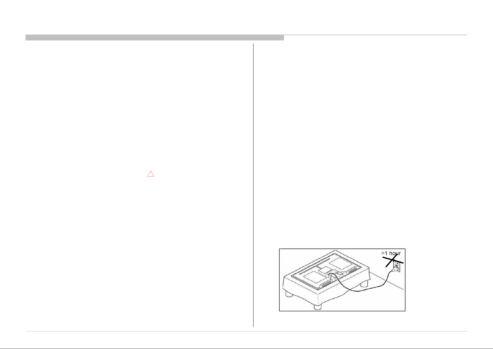
10) Dur i ng the r epai r , D O NO T l eav e the Pow er On or Burn-in period for more
than 1 hour w hil e the T V i s face dow n on a c l oth.
Figure 1. TV is faced down on a cloth during repair.
5
1-3. Caution About the Lithium Battery
1) Danger of explosion if battery is incorrectl y replaced. Replace only with
the same or equivalent type.
2) Outer case broken battery shoul d not contact to water.
1-4. Safety Check-Out
After correcting the original service problem, perform the following
safety checks before releasing the set to the customer:-
1) Check the area of your repair for unsoldered or poorly soldered
connections. Check the entire board surface for solder splashes and bridges.
2) Check the inter board wiring to ensure that no wires are pinched or
contact high-wattage resistors.
3)Check all control knobs, shields, covers, ground straps and mounting
hardware have been replaced. Be absolutely certain you have replaced all
the insulators.
4) Look for unauthorized replacement parts, particularly transistors that
were installed during a previous repair. Point them out to the customer and
recommend their replacement.
5) Look for parts which, though functioning show obvious signs of
deterioration. Point them out to the customer and recommend their
replacement.
6) Check the line cords for cracks and abrasion. Recommend the
replacement of any such line cord to the customer.
7) Check the antenna terminals, metal trim, metalized knobs, screws and all
other exposed metal parts for AC leakage. Check leakage test as described
next.
8. For safety reasons, repairing the Power board and/or Inverter board is
prohibited.
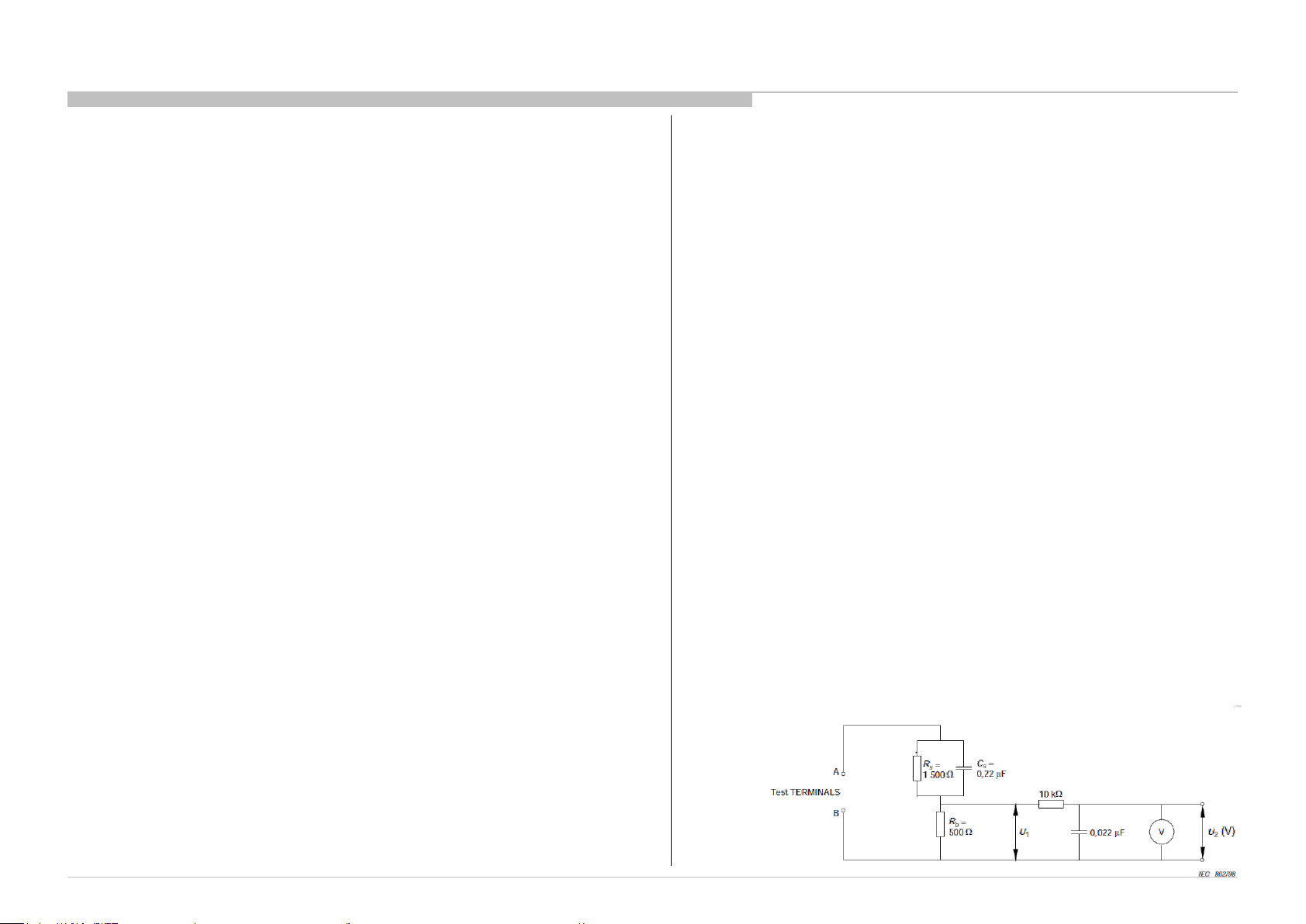
1-5.Leakage Test
(To protect elec tri c shock when custom er touch the ter minal .)
Leakage curr ent can be measured by V: Voltmeter or oscilloscope (r.m.s. or
peak reading)
Stabilized pow er supply instrument and isol ated voltage transform er:
Use too much curr ent c apacity and isol ated voltage tr ansformer does not
need to use stabili zed power supply equipm ent.
Specificati on of RM S volt meter: I nput res istanc e > 1 Mohm, Input
capacitance < 200 pF, Frequency range: 15 Hz – 1M Hz . Refer Figure 1.
Isolated ty pe volt -meter (FLUKE 8921A etc *1)
*1 Not use FLU KE 8920A that connect ed to protec tive earth by diode
# Leakage current of measurement instr ument is less than 10μArms when
under test equi pment AC plug is opened
# Set up the following conditi on and tur n on the set. Applied v oltage:
Nominal i nput volt age (Des cri ption on Nam eplate)
# Measur e the leakage cur rent bet ween one phas e conduc tor and neutral
for terminal 1 and terminal
2. Read rms value, and then calculate to peak value PEAK VALUE =√2
RMS VALUE
Comply w ith the following requir ement
Class II equipment (2-pin pl ug): for each ter mi nal, the w orst value of
measurement must not exceed AC 283uA peak).
Note: includi ng AC adaptor, AC adaptor/DC operated unit combi nation
Note: Pr oduct s which ar e al w ays used in touch w i th hum an body : 141uA
(peak)
Note: As for products destined for Southeast Asia (Rod Antenna is
accessory . Or it is packed with a pr oduc t.) , the worst value must not exceed
AC 141uA (peak).
Figure 1 – Measuring network
for Leakage Current
6
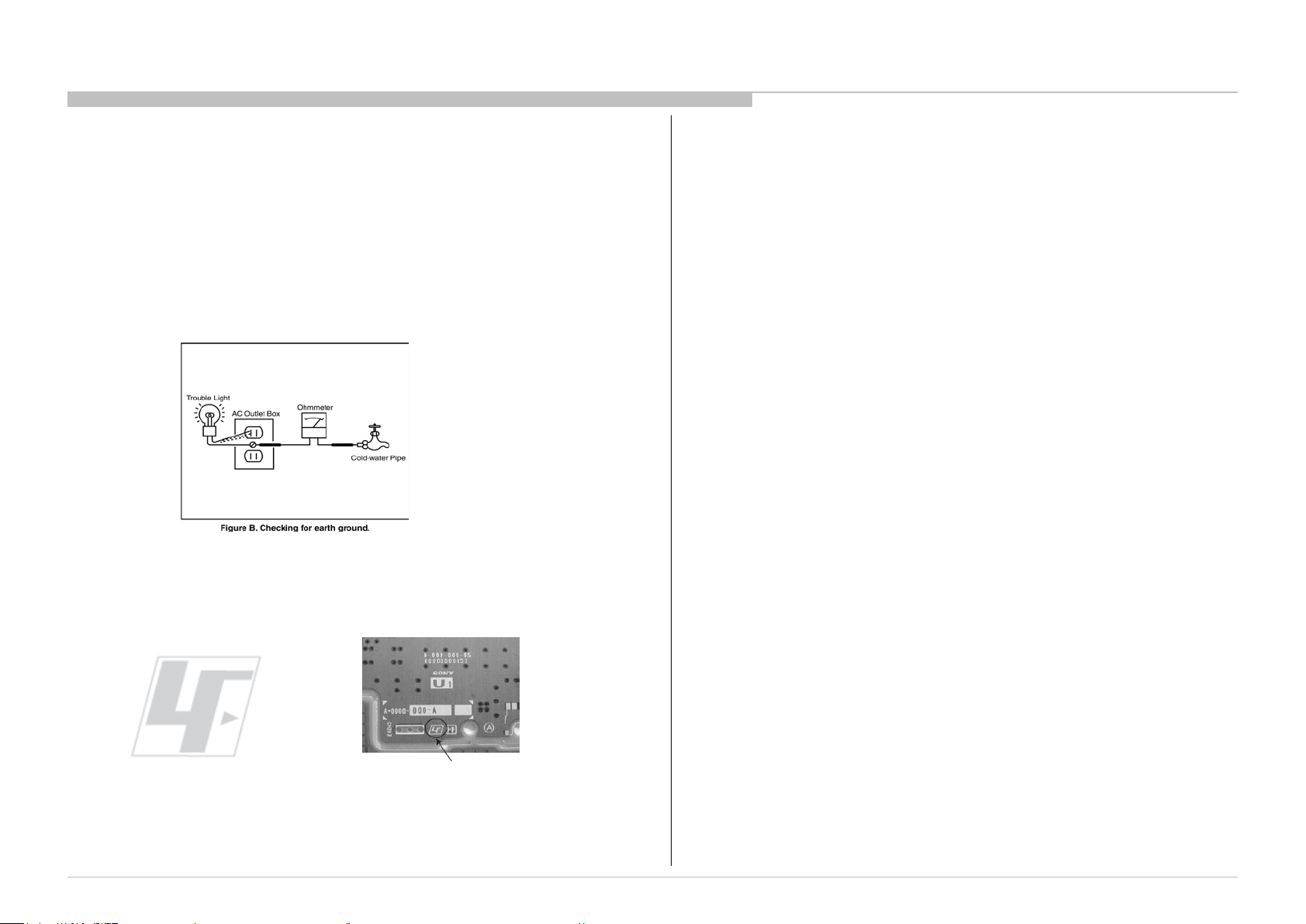
1-6. How to Find a Good Earth Ground
1) A cold-water pi pe is a guaranteed ear th ground; t he cover-pl ate retaini ng
screw on most AC outlet boxes i s also at earth ground.
2) If the retaining scr ew is to be used as your earth ground, veri fy that it is at
ground by measuri ng the resistanc e between i t and a c ol d-w ater pipe w ith an
ohmmeter. The readi ng should be zer o ohms.
3) I f a cold-w ater pi pe is not accessi ble, connect a 60- to 100-watt t roublelight (not a neon lamp) between the hot side of the recept acle and the
retaining scr ew. Tr y both slots, if necess ary, to locate the hot s ide on the line;
the l am p shoul d l i ght at normal br il l i ance i f the sc r ew i s at gr ound pot enti al
(see Figur e 3).
Figure 3. Checking for earth
ground.
1-7. Lead Free Information
The circui t boards used i n these model s have been pr ocessed using Lead
Free Solder. The boards ar e identified by the LF logo loc ated clos e to the
board designation.
The servic ing of these boar ds r equires special precautions. It is strongly
recommended to use Lead Free Solder m ateri al in order to guarantee optim al
Figure 4: LF Logo
Figure 5: LF logo on circuit board
quality of new solder joi nts.
7
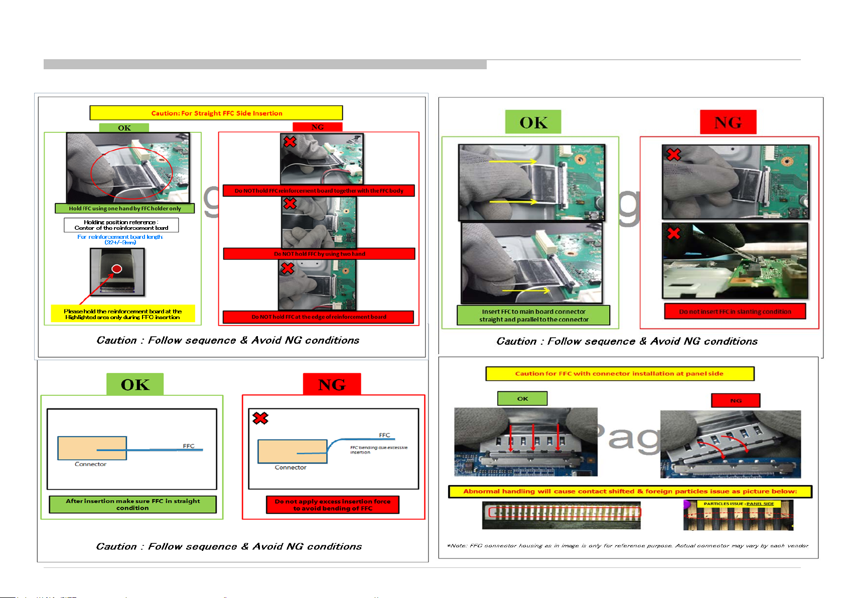
1-8. Handling the FLEXIBLE FLAT CABLE (FFC) ( continue )
8
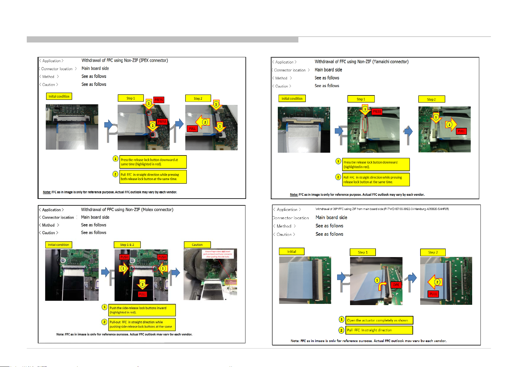
1-8. Handling the FLEXIBLE FLAT CABLE (FFC) ( continue )
9

1-8. Handling the FLEXIBLE FLAT CABLE (FFC) ( continue )
10
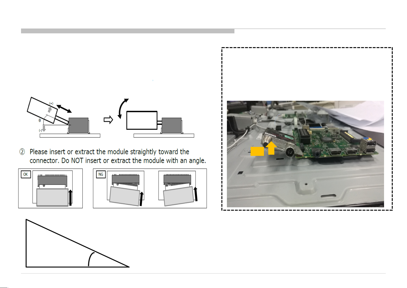
1-9. Solder-less tuner replacement procedure
Tuner Module treatment way
① The insertion & extraction angle of the module is permitted to
specified degree for connector
θ≒20°
Push down to screw.
For removing Tuner Module,
After un screwed, Automatically the Module
will float to correct degree.
So please extract it with keeping this degree.
20°
20°
Reference paper for 20 degree
(If need please use for fit by cutting t his paper)
11
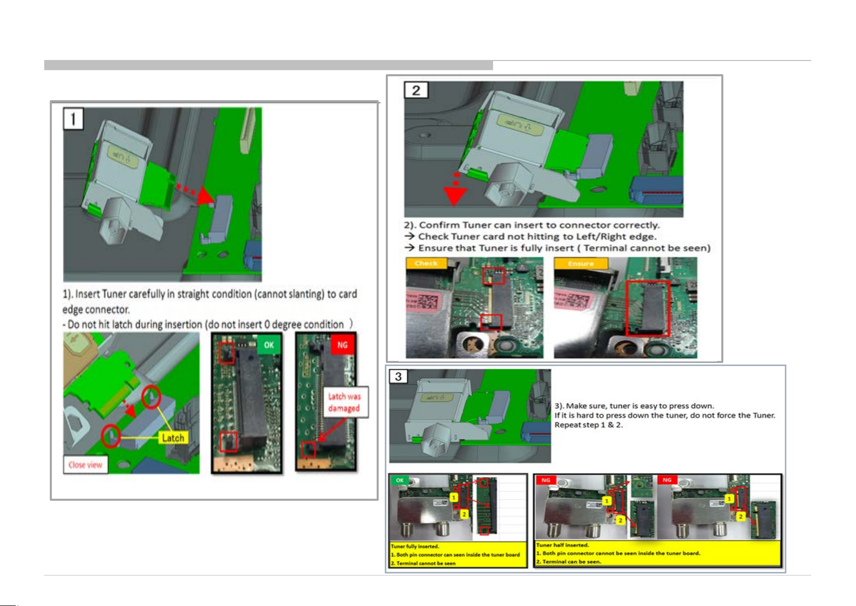
1-9. Solder-less tuner replacement procedure (Cont. )
12
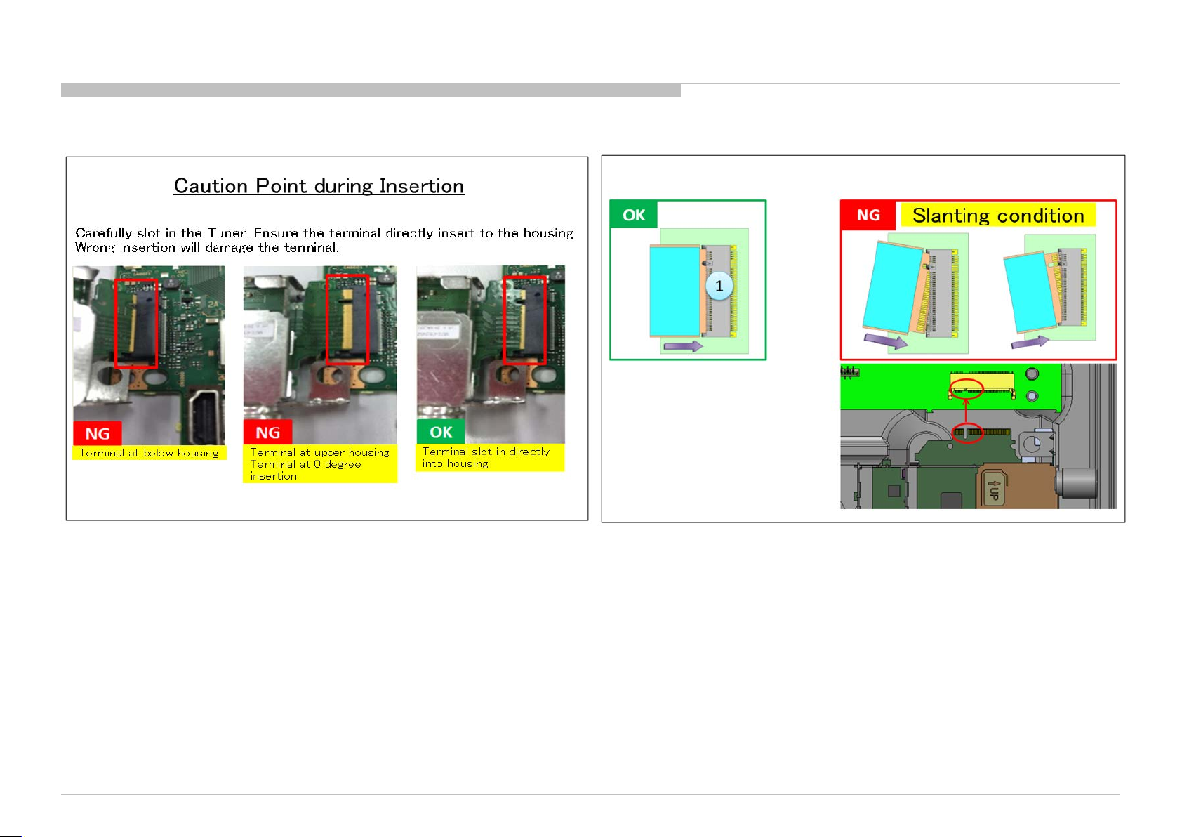
1-9. Solder-less tuner replacement procedure ( Cont. )
13
SECTION 2
SELF DIAGNOSTIC FUNCTION
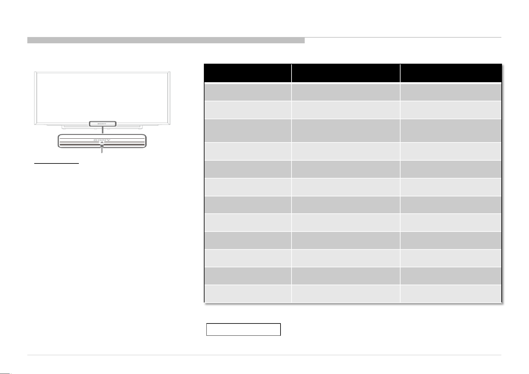
LED Indicator
• Lights up in white when you select “ Pict ure Off”.
• Lights up in amber when you set the tim er or
“Photo Frame Mode”.
• Lights up in white when the TV is turned on.
• Flashes whil e the remote is being oper ated.
Status
Power Off
( AC Off and *1)
Power On
Standby
( by remote control of f
and Side Key off)
Picture Off
Set "Sleep Timer"
Set "On Timer"
( Power On )
Set "On Timer"
( Standby )
Picture Frame
Failure
Error of panel ID
LED Colour
OFF
White
OFF
White
Amber
Amber
Amber
Amber
Red Blinking
Amber / Green Blinking
Remarks
*1 power swit ch of f (by Side
Key)
The number of LED blinking
indicates cause of failure.
Blinki ng:0.5sec Amber/ 0 .5sec
Green
Software Updating
Softwa re U pdati ng
failure
Amber = Red + Green
Amber Blinking
Amber / Red Blinking
Blinking: 1sec On / 1sec Off
Blinking:1 sec Amber/ 1sec R ed
14
The Number of Standby LED
(RED blinking)
Error Detection Error Location
2 Main Powe r Error AC Adaptor
3 Audio Error Main Board or Sub Board (LK)
4 Panel Po wer E rror Main Board
5 Panel I2C Comm Error Main Bo ard or Source Board
6 Backli ght E rror Main Board or Sub Board (LK)
Tuner Demod Error, BE_I2C Error and PMIC_I2C do not go to Safety Shutdown and
do not have RED blinking.
Error Detection Symptoms Error Location
Tuner Demod Error Cannot tune Digital RF/ Analog RF Main Board/Tuner Module
BE I2C Error No picture display Main Board
PMIC I2C error No power Main Board
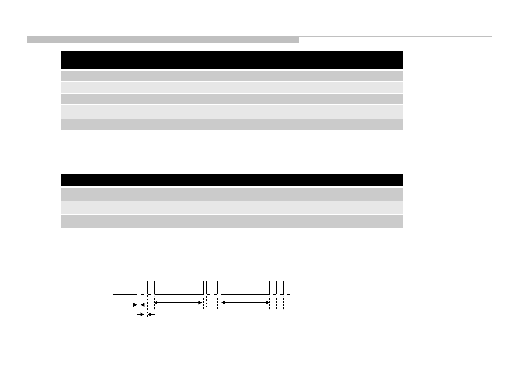
LED Pattern
When safety shutdown occurs, Standby LED display reports the cause by using the lightning patterns as indicated below.
0.5sec
Example: The figure above shows LED display when SHUTDOW N is caused by Audio Error.
It repeats f lashing f or a specified number of times in 0.5s ec/cycl e and has a 3 seconds interval of lighting off.
Please note t hat a 3 sec onds int erv al of light ing off is fixed regar dl ess of abnor m al s tate typ es.
0.5sec
3.0sec 3.0sec
15
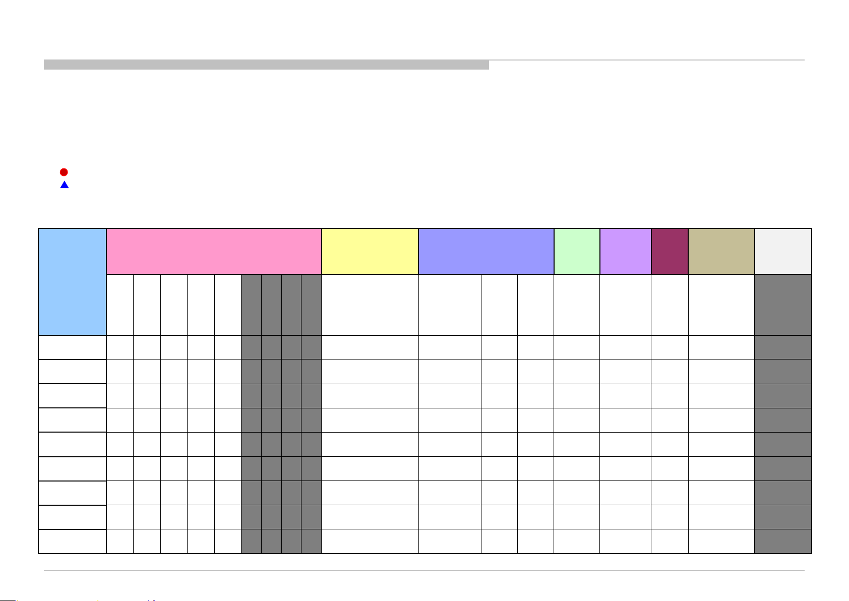
Triage C hart
Before you make t he service cal l…
1. Confirm the symptom from the customer.
2. Select that sympto m fro m the chart.
3. Bring a ll the b o a r d s and ca b les liste d for that symp to m.
4. Follow the troub lesho oting c harts in the technical guid es to isolate the boar d.
5. Chart
Remote
Smart Core
(KL) / LED
Bluetooth
reponse to remote
Stationary
dots
One of
no LED (Set
Bluetooth
/ One Step
(OSR)can't
Wifi Module
Color Code
RED DOT: Mo st likely defective pa r t
BLUE TRIANGLE: Secondary possible defective part
ABC BLACK TEXT: Board that may correct the symptom
GN3UN Chassis
Reference
Symptoms - Shutdown. Power LED
blinking red diagnostics sequences
2 3 4 5 6 7 8 9 10
No White Po wer
LED & does not
No
Power
(Dead Set)
B* Board
LK* Board
H* Board
K* Board
Speaker &
Subwoofer
Adaptor
LCD Panel
Tcon
Video
- mi ssing or distorted
colored
lines or
No
video
Inputs
No
video
all
Inputs
Network Audio
(KM)
No
Remote
Wireless
can't
connect
Audio
No
Smart Core
is still alive)
(BT)
Remote
connect
16
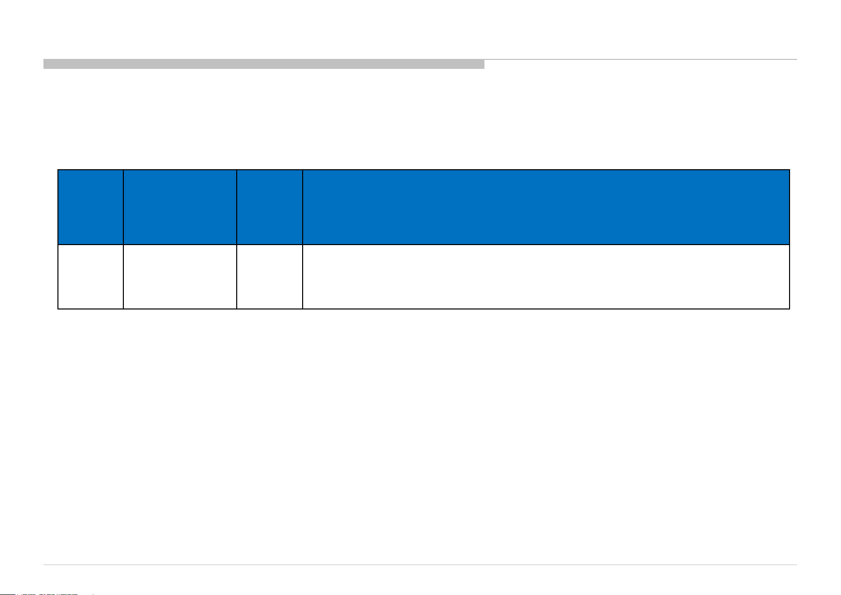
Problem/Issue
SECTION 3
Trouble Shooting Flow
3a Trouble Shooting Flow 2x blinking – Main Power Error
Section
3
2x blinking –
Main Powe r Error
Title
3a.1 2x blinking – Main Power Error
17
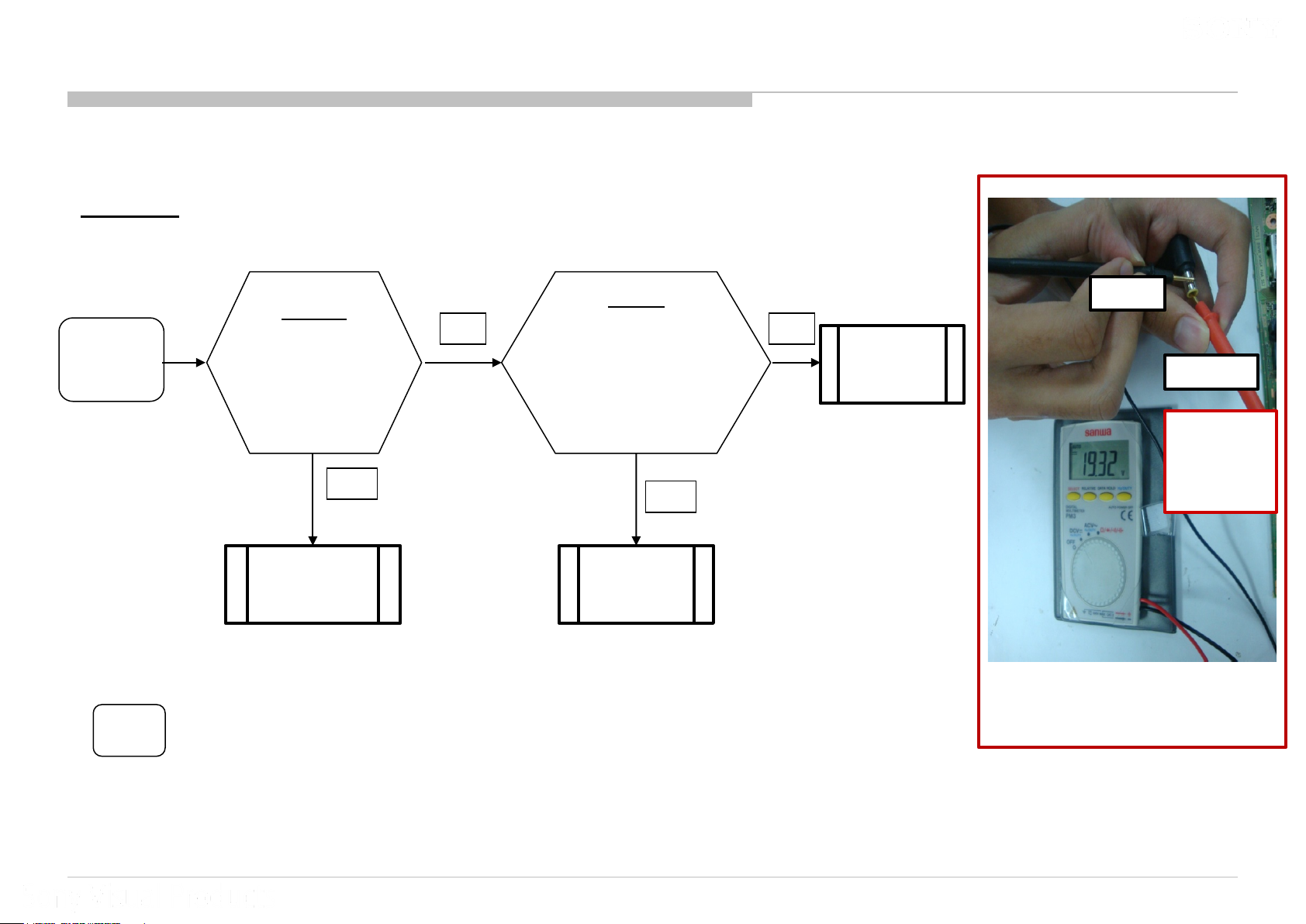
3a.1. 2x Blinking – Main Power Error
LK Board
2 times
Blinking
*For LK2
LK-Board
Check DC voltage at
Q6020/ *Q6022
18V – 22.5V?
*Typical: 19.5V
Yes
Change LK-
board
No
Adaptor
Take out adaptor
and check the output voltage.
18V – 22.5V?
(Refer Figure 1)
*Typical: 19.5V
Yes
Change LK-
Board
No
Change
Adaptor
-ve
+ve
Ensure that
+ve probe is
touching the
needle.
Figure 1: How to check adaptor’s output
voltage.
18
3a.1 : 2x Blinking – Main Power Error
LK Board (Checking point)
Board Name Board PWB (A side) Detail
LK1
(Q6020)
19.5
V
Q6020
LK2
(Q6020 &
Q6022)
19.5
V
Q6020 &
Q6022
19

Problem/Issue
3b Trouble Shooting Flow 3x blinking – Audio Error
Section
3
3x blinking –
Audio Error
Title
3b.1 3x blinking – Audio Error
20
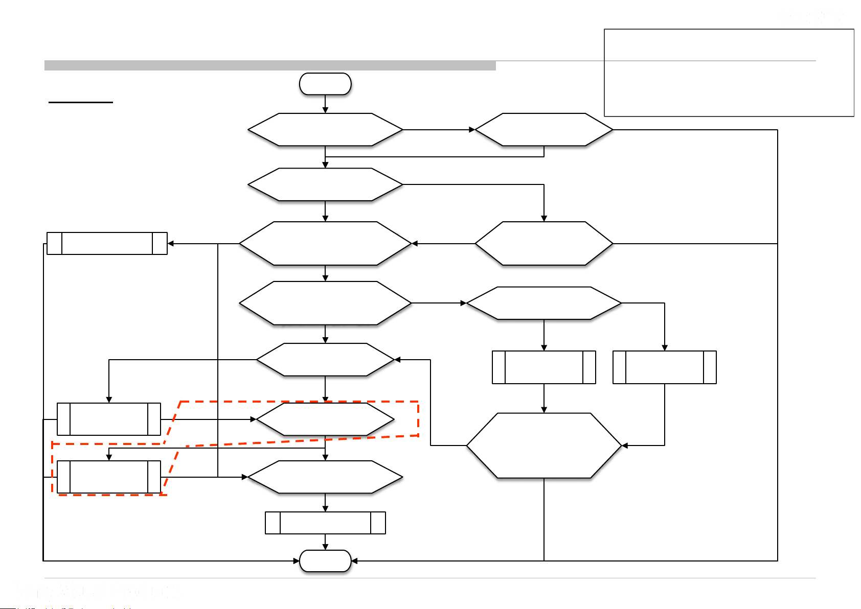
3b.1 : 3x Blinking – Audio Error
START
LK Board
Check FFC correct insert? Insert FFC correctly
3x blinking
Important No te :
TV must be power OFF condition before plug
or unplug any of the FFC/FPC /wire / cable
from the board. -> This is to preven t
possibility c ir cuit damag e h a ppen.
FFC not insert correctly
Change B-board
LK-board Audio Error p in
short to GND
No connectivity of F4001
F4001 broken,
Replace
F4001
F4101 broken,
Replace
F4101
Check correct Option bit is set?
B-board Audio Error pin
short to GND
3x blinking
No connectivity of F4101
3x blinking
Disconnect B-board to LK-board FFC
Remove Speaker Connector
#Audio IC (IC4001/IC4101) p roblem
3x blinking
Correct Option bit & 3x blinking
and check Audio E rror pin
Audio Error pin no short to GND
at CN4001/CN4002 an d
perform AC OFF - ON
3x blinking
Check connectivity
of F4001
3x blinking & F4001 OK
Check connectivity
of F4101
3x blinking & F4101 OK
3x blinking
Wrong Option bit
3x blinking
No 3x blinking
3x blinking
Set correct O ption bit an d
perform AC OFF - ON
Check Speaker harness and
Speaker impedance
Speaker harness
shorted
Change
Speaker
Harness
Connect back
Speaker Connector
to CN4001/CN4002 an d
perform AC OFF - ON
No 3x blinking
Main or Assist Speaker
Impedance ≠ 6~8 Ω
Change Main
or Assist
Speaker
For model with Assist Spe aker only
Change LK-board
No 3x blinking
DONE
Note : IC4101 and F4101 available to check for model with woofer (Assist Speake r) only.
No 3x blinking
21
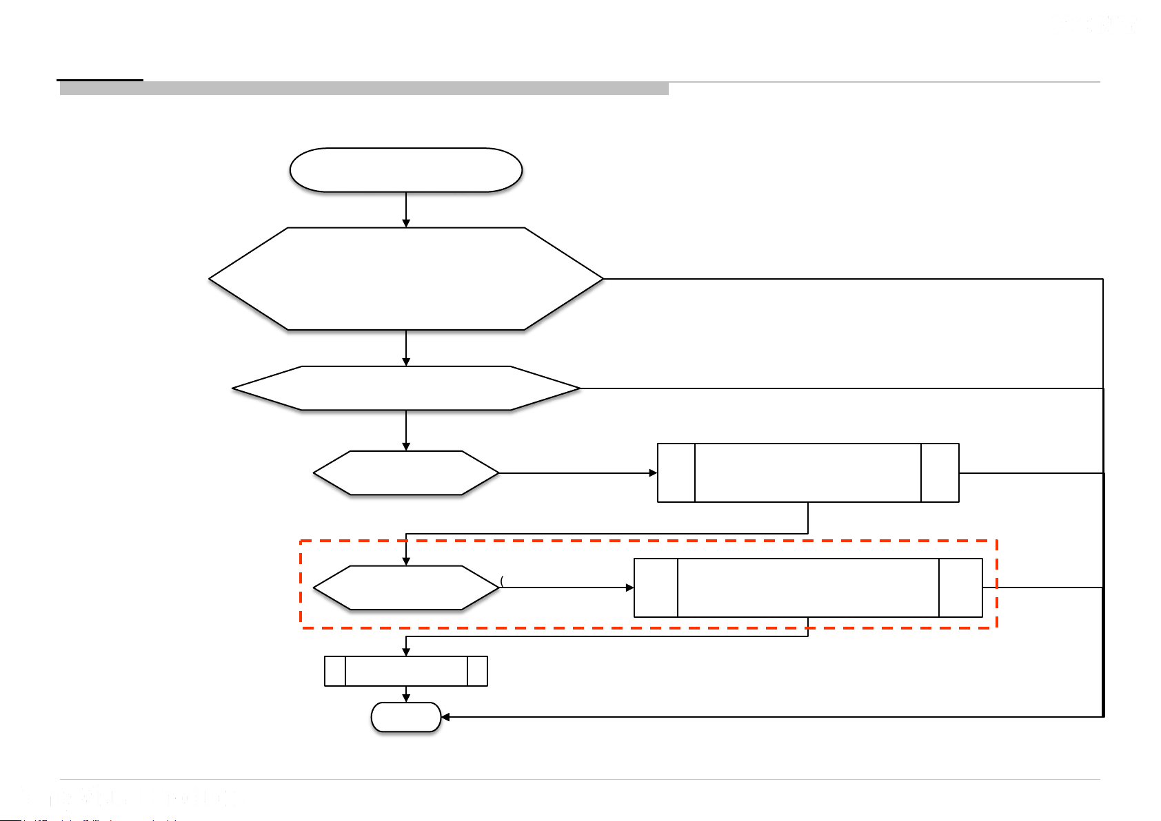
3b.1 : 3x Blinking – Audio Error
LK Board
Important No te :
(#Audi o IC (IC4001/IC4101) problem)
#Audio IC (IC4001/IC4101) p roblem
3x blinking and F4001 & F4101 OK
Check Audio IC pins and surrounding part,
Replace the NG part if have any
(For example, fuse broken, e.capacitor blow,
c.capacitor short connection, zener diode open or short,
inductor open connection and etc.)
3x blinking
Check have any burn mark on Audio IC,
If have burn mark, replace the NG Audio IC
3x blinking
Disable Error Detection,
Remove F4101 if have
START
Main Speaker No Sound
(Ignore Assist Speaker if have)
3x blinking
TV must be power OFF condition bef o r e
plug or unplug any of the FFC/FPC/wire
/cable from the board. -> This is to prevent
possibility c ir cuit damag e h a ppen.
Remember enable back Error Detection if
previously h a v e disable it .
IC4001 problem, Change IC4001,
Mount back F4101 if have removed,
Enable back Error Detection
No 3x blinking
No 3x blinking
No 3x blinking
For model with
Assist Speaker only
Note : IC4101 and F4101 available to check for model with woofer (Assist Speake r) only.
Disable Error Detection,
Remove F4001
Change LK-board
DONE
Assist Speaker No Soun d
(Ignore Main Speaker)
3x blinking
IC4101 problem, Change IC4101,
Mount back F4001 & F4101 if have removed,
Enable back Error Detection
No 3x blinking
22
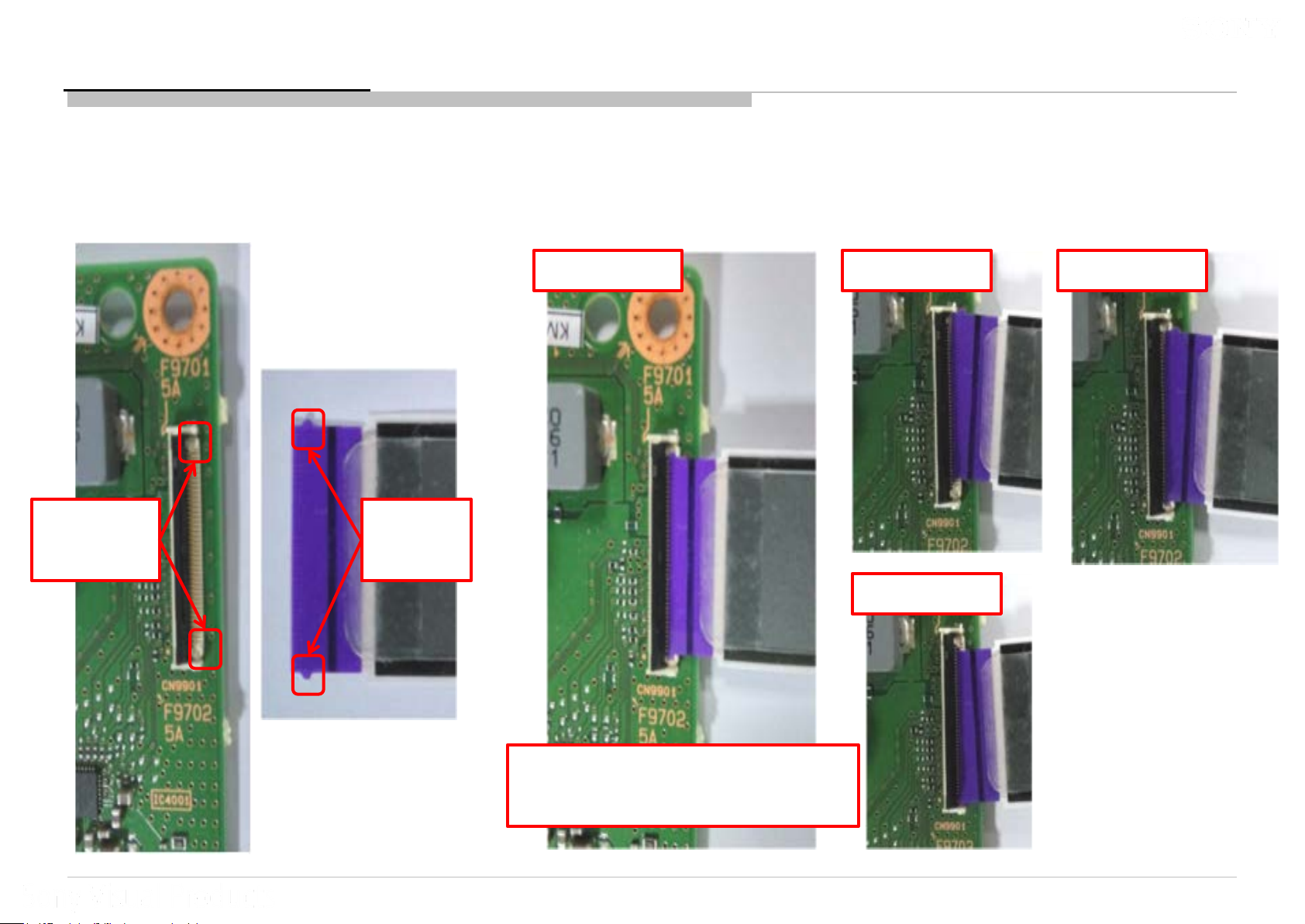
3b.1 : 3x Blinking – Audio Error
LK1/2 Board (FFC insertion)
Same apply to B-board FFC connector side
Important No te :
TV must be power OFF condition bef o r e
plug or unplug any of the FFC/FPC/wire
/cable from the board. -> This is to prevent
possibility c ir cuit damag e h a ppen.
OK example NG example NG example
Guide at
Connector
Guide at
FFC
NG example
FFC guide need insert fully over
the connector guide
23
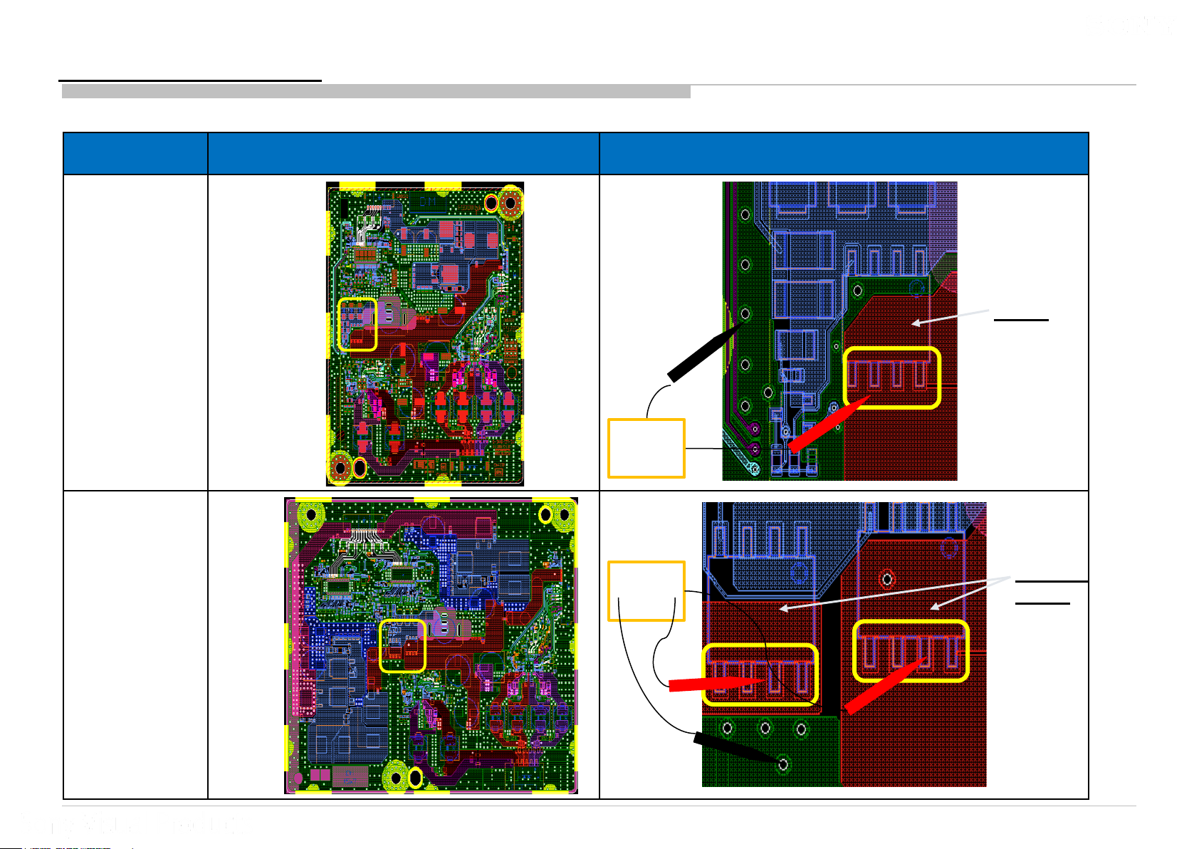
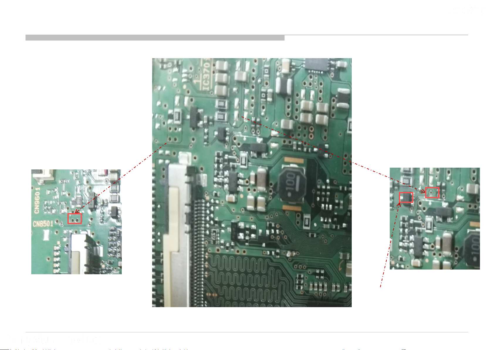
3b.1 : 3x Blinking – Audio Error
BLM Board (Checking Point)
Board
PWB
(A side)
Checking
Audio Error
pin not short
to GND
BLM (KM, KMW, KML, KMLW, KL, KLW) Details
Details
CN9601
Main IC
(IC5000)
Audio Error pin
24
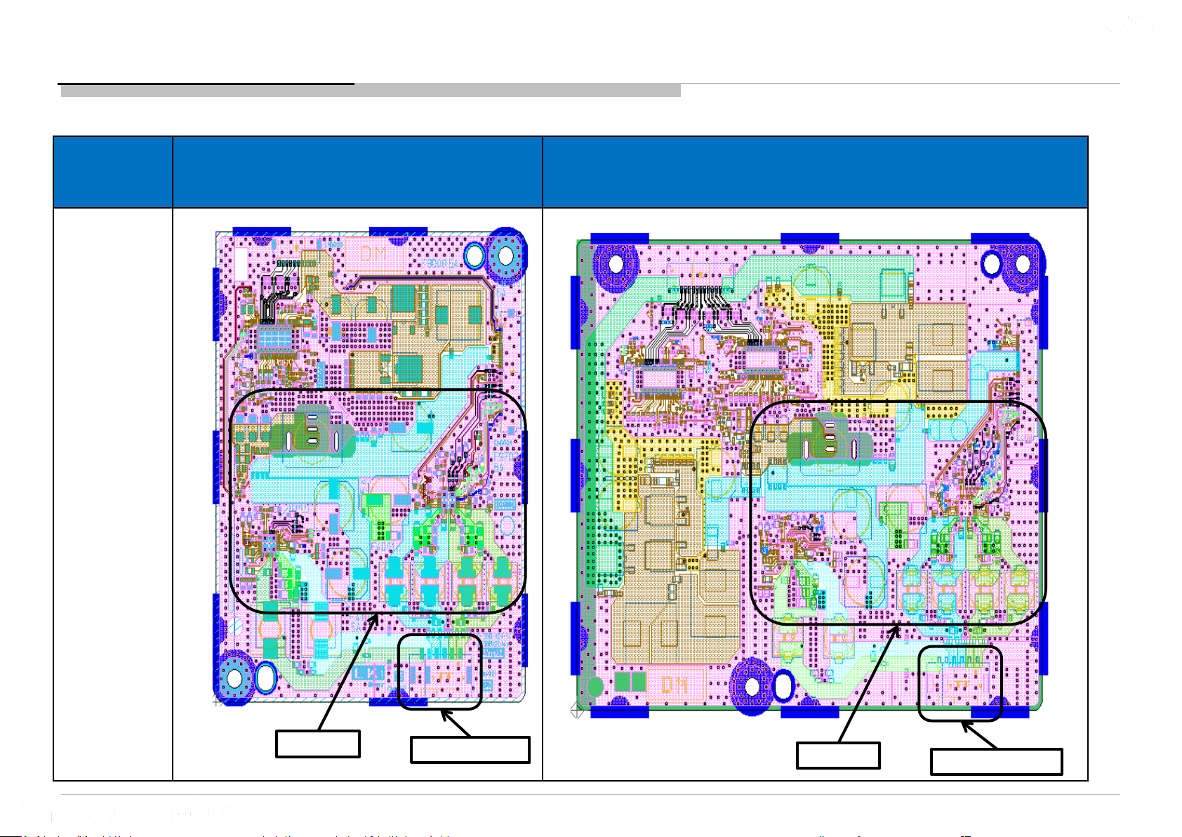
3b.1 : 3x Blinking – Audio Error
LK1/2 Board (Checking Point)
Board PWB
(A side)
Detail refer
next slide
LK1 (KM, KMW, KML, KMLW, KL, KLW) LK2 (KL, KLW)
Details
CN4001/CN4002
Details
CN4001/CN4002
25
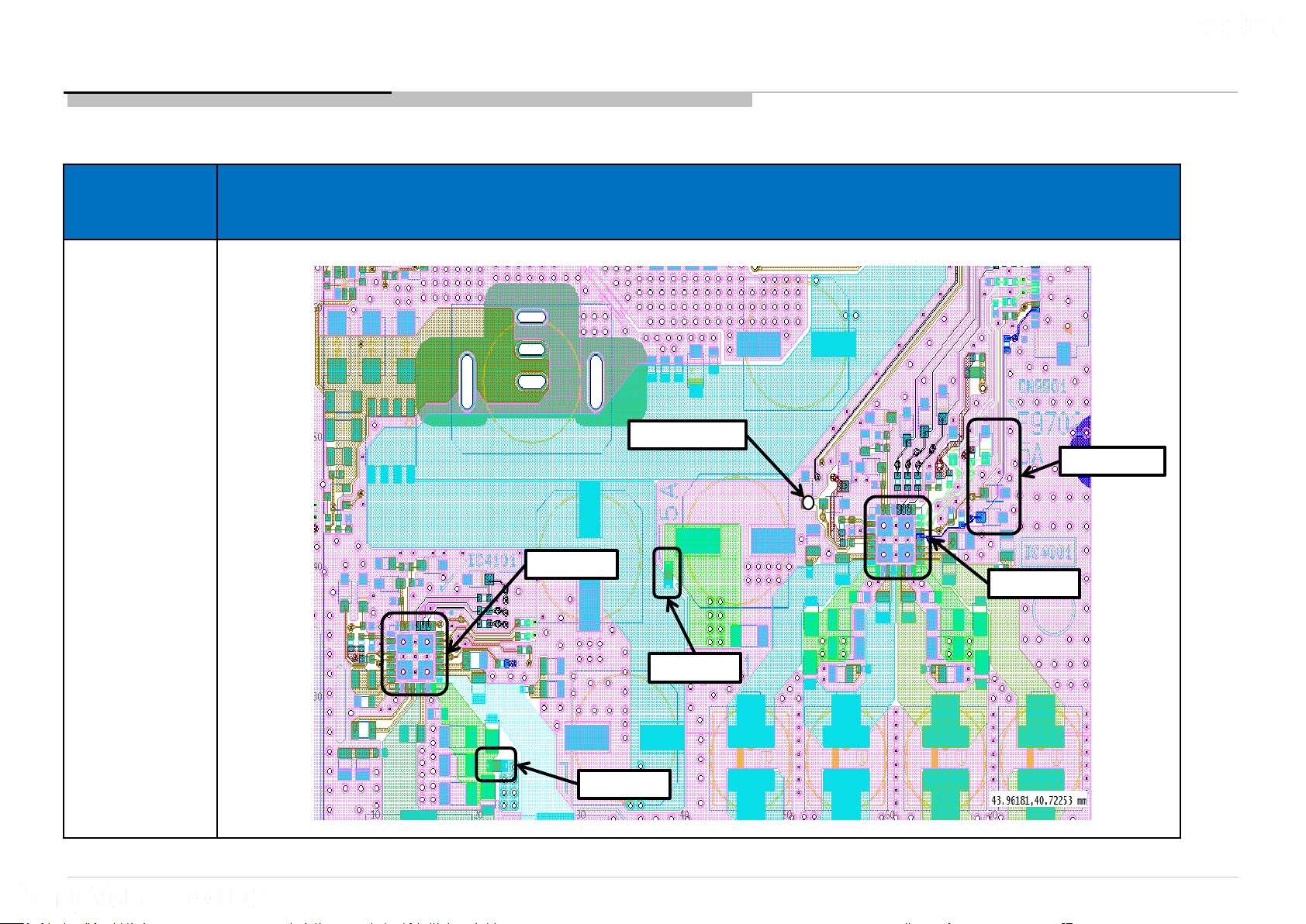
3b.1 : 3x Blinking – Audio Error
LK1/2 Board (Checking Point)
Board PWB
(A side)
Purpose :
Checking Audio
Error pin not
short to GND
Checking fuse
condition
Change Audio IC
if need
Audio IC each pin
checking, please
refer to “Audio
No Sound”
Details
Audio Error pin
Zener Diode
IC4101
IC4001
F4101
F4001
26

Problem/Issue
3c Trouble Shooting Flow 4x blinking – Panel Power Error
Section
3
4x blinking –
Panel Po wer E rror
Title
3c.1 4x blinking – Panel Power E rror
27
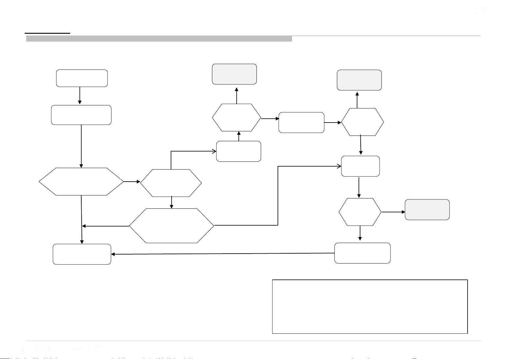
3c.1 : 4x Blinking – Panel Power Error
BLM Board
Start
*Check LK board FFC
Or LVDS FFC
TV boot up normally?
Yes
End
Yes
No
No
Check PANEL_PWR
3.00V-3.33V?
Check voltage at
+12V_PANEL
11-V-12.82V?
Yes
TV was in
standby
Yes
TV turn on
Normally?
RC ON
No
No
Replace
Main IC / B-
Board
B-Board/Main
IC problem
Yes
TV turn on
Normally?
No
Replace
LK board
TV turn on
Normally?
No
Replace O-cell/
Panel module
Yes
LK board
problem
*Check LK board FFC Or LVDS FFC
Step 1: Rem ove and reinsert both FFC in correct position
Step 2: Replace w ith new FFC
28
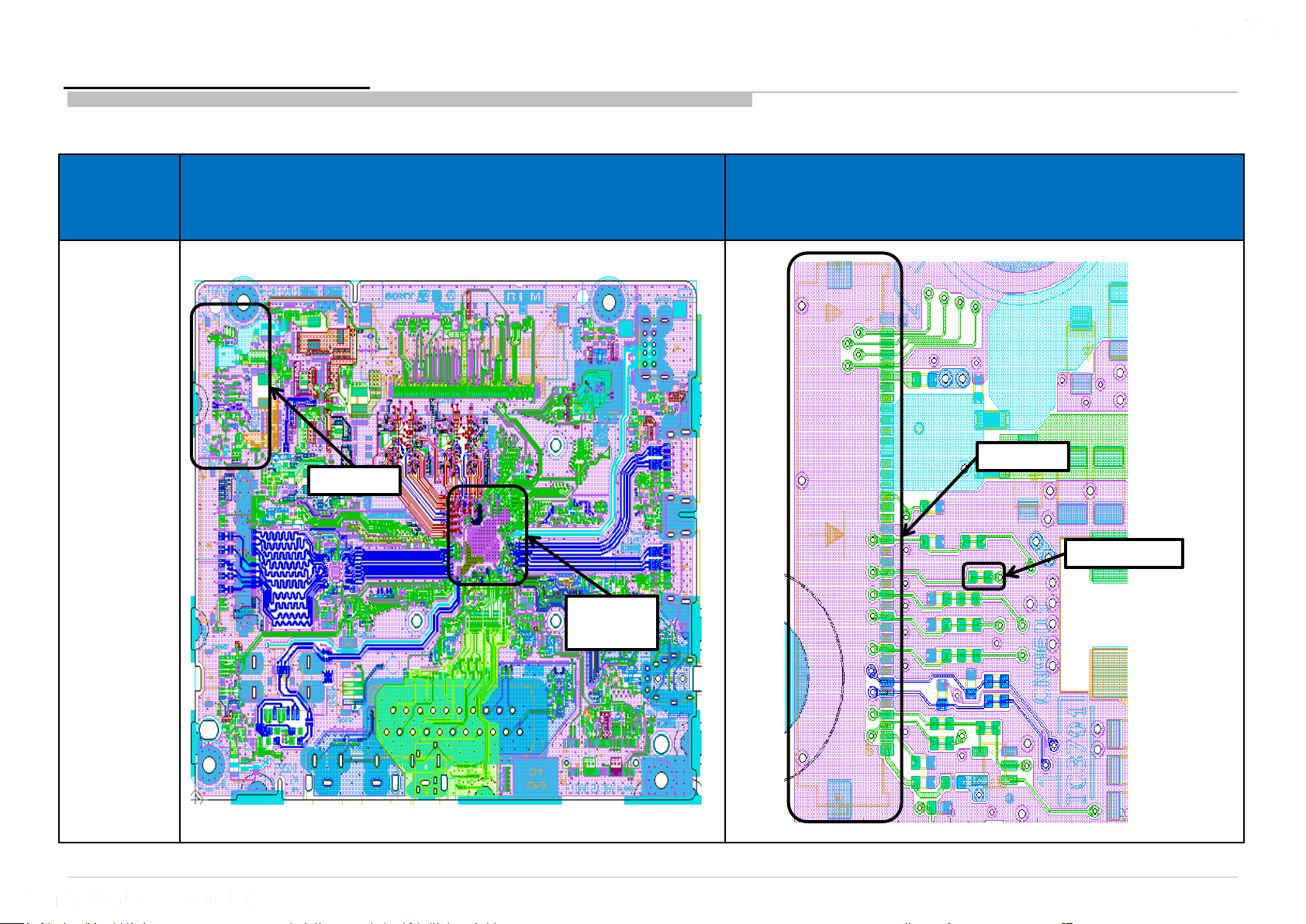
BLM layout
+12V_PANEL line
PANEL_PWR
Q6001
Only present in EU regions
29
Problem/Issue
3d Trouble Shooting Flow 5x blinking – Panel I2C Er ror
Section
3
5x blinking –
Panel I2C Error
Title
3d.1 5x blinking – Panel I2C Error
30
 Loading...