

SONY KDL 32S5100 Diagram

HISTORY INFORMATION FOR THE FOLLOWING MANUAL:
SERVICE MANUAL
MODEL NAME REMOTE COMMANDER DESTINATION
KDL-32S5100
KDL-32S5100
KDL-40S5100
KDL-40S5100
KDL-46S5100
KDL-46S5100
RM-YD028 US/CND
RM-YD028 MX/LATIN AMERICA
RM-YD028 US/CND
RM-YD028 MX/LATIN AMERICA
RM-YD028 US/CND
RM-YD028 MX/LATIN AMERICA
EX2R
CHASSIS
ORIGINAL MANUAL ISSUE DATE: 2/2009
:UPDATED ITEM
☛
REVISION DATE SUBJECT
2/2009 No revisions or updates are applicable at this time.
2/2009 Corrected model destination groupings. Replaced pages 1 and 2.
Updated Specifi cation Section. Replaced pages 4-12.
Updated Disassembly Section. Replaced page 18.
Updated Wire Dressing Diagrams. Replaced pages 20-47.
Added Support Belt Kit P/N for KDL-32S5100. Repaced page 107.
4/2009 Updated Accessories and Packing. New AC Power Cords. Corrected part descriptions for
Support Belt Kits and added contents. Added contents for Screw Bag Assy. Replaced page 107.
9/2009 Updated Exploded View Section to remove LCD Panel specifi c information. Replaced page 81.
Corrected model reference for KDL-32S5100 AC Power Cord. Replaced page 107.
LCD DIGITAL COLOR TELEVISION
9-883-810-04
Self Diagnosis
Supported model
SERVICE MANUAL
MODEL NAME REMOTE COMMANDER DESTINATION
KDL-32S5100
KDL-32S5100
KDL-40S5100
KDL-40S5100
KDL-46S5100
KDL-46S5100
RM-YD028 US/CND
RM-YD028 MX/LATIN AMERICA
RM-YD028 US/CND
RM-YD028 MX/LATIN AMERICA
RM-YD028 US/CND
RM-YD028 MX/LATIN AMERICA
EX2R
CHASSIS
9-883-810-04
CCDISPLAY POWER
WIDE INPUT
TOOLS
KDL-46S5100 RM-YD028
LCD DIGITAL COLOR TELEVISION

KDL-32S5100/40S5100/46S5100
TABLE OF CONTENTS
SECTION TITLE PAGE SECTION TITLE PAGE
Specifications ................................................................................. 4
Warnings and Cautions - English ................................................... 6
Warnings and Cautions - French .................................................... 7
Safety-Related Component Warning .............................................. 8
Safety Check-Out ......................................................................... 10
Self-Diagnostic Function ................................................................11
SECTION 1: DISASSEMBLY ............................................................... 13
1-1. Rear Cover Removal ............................................................ 13
1-2. Switch Unit Removal ............................................................ 13
1-3. BM3 Board and Power Board Removal ............................... 14
1-4. Table-Top Stand Assembly and Under Cover Removal ....... 15
1-5. Structural Parts Removal ..................................................... 15
1-5-1. KDL-32S5100 Only .................................................. 15
1-5-2. KDL-40S5100 Only .................................................. 16
1-5-3. KDL-46S5100 Only .................................................. 16
1-6. Loudspeaker, Under Bar, IR/LED Removal .......................... 17
1-7. LCD Panel Removal ............................................................. 18
1-7-1. Cleaning the LCD Panel .......................................... 18
1-8. Inverter Board Removal (KDL-32S5100 Only) ..................... 19
WIRE DRESSING ........................................................................ 20
KDL-32S5100 ONLY ............................................................ 20
KDL-40S5100 ONLY ............................................................ 30
KDL-46S5100 ONLY ............................................................ 39
SECTION 2: SERVICE ADJUSTMENTS ............................................. 48
2-1. Viewing Service Adjustment Data ........................................ 48
2-2. Accessing Service Mode ...................................................... 48
2-2-1. Entering the Serial Number
after changing the Main Board ................................. 48
2-2-2. Resetting to Factory Defaults .................................. 49
SECTION 3: DIAGRAMS ..................................................................... 50
3-1. Circuit Boards Location ........................................................ 50
3-2. Printed Wiring Boards and
Schematic Diagrams Information ......................................... 50
3-3. Block Diagram ...................................................................... 52
3-4. Schematics and Supporting Information .............................. 53
BM3 Board Schematic Diagram (1 of 9) .............................. 53
BM3 Board Schematic Diagram (2 of 9) .............................. 54
BM3 Board Schematic Diagram (3 of 9) .............................. 55
BM3 Board Schematic Diagram (4 of 9) .............................. 56
BM3 Board Schematic Diagram (5 of 9) .............................. 57
BM3 Board Schematic Diagram (6 of 9) .............................. 58
BM3 Board Schematic Diagram (7 of 9) .............................. 59
BM3 Board Schematic Diagram (8 of 9) .............................. 60
BM3 Board Schematic Diagram (9 of 9) .............................. 61
G2BE Board Schematic Diagram (KDL-32S5100 Only) ...... 63
HLR1 Board Schematic Diagram ......................................... 65
HSR Board Schematic Diagram ........................................... 67
IP1 Board Schematic Diagram (1 of 2)
(KDL-40S5100 Only) ............................................... 69
IP1 Board Schematic Diagram (2 of 2)
(KDL-40S5100 Only) ............................................... 70
IP2 Board Schematic Diagram (1 of 2)
(KDL-46S5100 Only) .............................................. 72
IP2 Board Schematic Diagram (2 of 2)
(KDL-46S5100 Only) .............................................. 73
3-5. Semiconductors ................................................................... 76
SECTION 4: EXPLODED VIEWS ........................................................ 77
4-1. Rear Cover Assembly and Table-Top Stand Assembly ....... 77
4-2. Chassis ................................................................................ 78
4-3. Connectors (KDL-32S5100 Only) ........................................ 79
4-4. Connectors (KDL-40S5100/46S5100 Only) ......................... 80
4-5. Bezel Assembly and LCD Panel .......................................... 81
4-6. Screw Legend ...................................................................... 82
KDL-32S5100/40S5100/46S5100
SECTION 5: ELECTRICAL PARTS LIST ............................................ 83
APPENDIX A: ENCRYPTION KEY COMPONENTS ..........................A-1
3
SPECIFICATIONS
KDL-32S5100/40S5100/46S5100
Power Requirements
Power Consumption (W)
In Use (Max)
In Standby
120V AC, 60Hz
HDMI IN 1/2/3:
HDMI: Video: 480i, 480p, 720p, 1080i,1080p, 1080/24p
Audio: Two channel linear PCM 32, 44.1 and 48 kHz, 16, 20 and 24 bits
120W (KDL-32S5100 only)
200W (KDL-40S5100 only)
245W (KDL-46S5100 only)
AUDIO
500 mVrms (Typical)
Impedance: 47 kilohms
Less than 1 W
AUDIO OUT:
VIDEO (IN) 1/2:
500 mVrms (Typical)
S Video (4-Pin Mini DIN (VIDEO 2 Only)
Y: 1.0 Vp-p, 75 ohms unbalanced, sync negative
C: 0.286 Vp-p (Burst signal), 75 ohms
DIGITAL AUDIO OUT (OPTICAL):
PCM optical signal
Video
1 Vp-p, 75 ohms unbalanced, sync negative
Audio
PC IN:
D-sub 15-pin, analog RGB, 0.7 Vp-p, 75 ohms, positive
500 mVrms (Typical)
Impedance:47 kilohms
PC AUDIO INPUT:
Stereo mini jack, 500 mVrms (Typical)
COMPONENT IN 1/2:
YP
(Component Video)
BPR
Impedance: 47 kilohms
Y:1.0 Vp-p, 75 ohms unbalanced, sync negative
PB:0.7 Vp-p, 75 ohms
PR:0.7 Vp-p, 75 ohms
Signal format: 480i, 480p, 720p, 1080i, 1080p
AUDIO
500 mVrms (Typical)
Impedance: 47 kilohms
Licensing Information
☛
Macintosh is a trademark of Apple Inc.,
registered in the U.S. and other countries.
HDMI, the HDMI logo and
High-Definition Multimedia Interface are
trademarks or registered trademarks of
HDMI Licensing, LLC.
Fergason Patent Properties, LLC:
U.S. Patent No. 5,717,422
U.S. Patent No. 6,816,141
Manufactured under license from Dolby
Laboratories. Dolby and the double-D
symbol are trademarks of Dolby
Laboratories.
TruSurround XT, SRS and (z) symbol are
trademarks of SRS Labs, Inc. TruSurround
XT technology is incorporated under
license from SRS Labs, Inc.
Blu-ray Disc is a trademark.
“BRAVIA”, , BRAVIA Sync
and are trademarks or registered
trademarks of Sony Corporation.
“PLAYSTATION” is a registered
trademark and “PS3” is a trademark of
Sony Computer Entertainment Inc.
KDL-32S5100/40S5100/46S5100
Design and specifi cations are subject to change without notice.
4
Speaker Output
1/2
7/8
3/4
1/4
3/8
3/4
Speaker/Full Range (2)
mm
in
Dimensions (W x H x D)
with stand
mm 798 x 583 x 227 mm 987 x 683 x 271 mm 1,123 x 770 x 323 mm
in
without stand
mm 798 x 536 x 89 mm 987 x 636 x 93 mm 1,123 x 723 x 96 mm
in
wall-mount hole pattern (mm) 200 x 200
wall-mount screw size (mm)
Mass
with stand
kg 13.1 kg 18.5 kg 25.5 kg
lbs 28.9 lbs 40.8 lbs 56.2 lbs
without stand
kg 11.9 kg 16.8 kg 22.6 kg
lbs 26.3 lbs 37.1 lbs 49.8 lbs
31
x 23 x 9 in 38
1/2
1/8
31
x 21
5/8
x 3
in 38
10 W+ 10 W
35 X 175
7/16
1
x 7
x 27 x 10
7/8
1/8
x 25
x 3
M6 x 8-12 mm
in 44
3/4
in 44
300 x 300
All measurements are approximations.
KDL-32S5100/40S5100/46S5100
KDL-46S5100KDL-40S5100KDL-32S5100
x 30
x 12
in
1/4
1/2
x 3
7/8
in
x 29
Television system
NTSC American TV Standard
ATSC (8VSB terrestrial) ATSC compliant 8VSB
QAM on cable ANSI/SCTE 07 2000
Channel coverage
Analog
2-69 Terrestrial
1-135 Cable
Digital
2-69 Terrestrial
1-135 Cable
Antenna
75-ohm external terminal for RF inputs
Panel System
LCD (Liquid Crystal Display) Panel
Display Resolution (horizontal x vertical)
1,920 dots x 1,080 lines
Screen Size (measured diagonally)
~ 31.5” (KDL-32S5100 only)
~ 40” (KDL-40S5100 only)
~ 46” (KDL-46S5100 only)
Supplied Accessories
Remote Commander RM-YD028
Two Size AA (R6) Batteries
Cable Holder (1 attached to the TV)
Operating Instructions
Quick Setup Guide
Warranty Card
Safety and Regulatory Booklet
Attaching the Table-Top Stand Flyer
Screws (4)
Optional Accessories
Connecting Cables
Wall-Mount Bracket
SU-WL500
KDL-32S5100/40S5100/46S5100
5
KDL-32S5100/40S5100/46S5100
WARNINGS AND CAUTIONS - ENGLISH
CAUTION
These servicing instructions are for use by qualifi ed service personnel only. To reduce the risk of electric shock, do not perform any servicing other
than that contained in the operating instructions unless you are qualifi ed to do so.
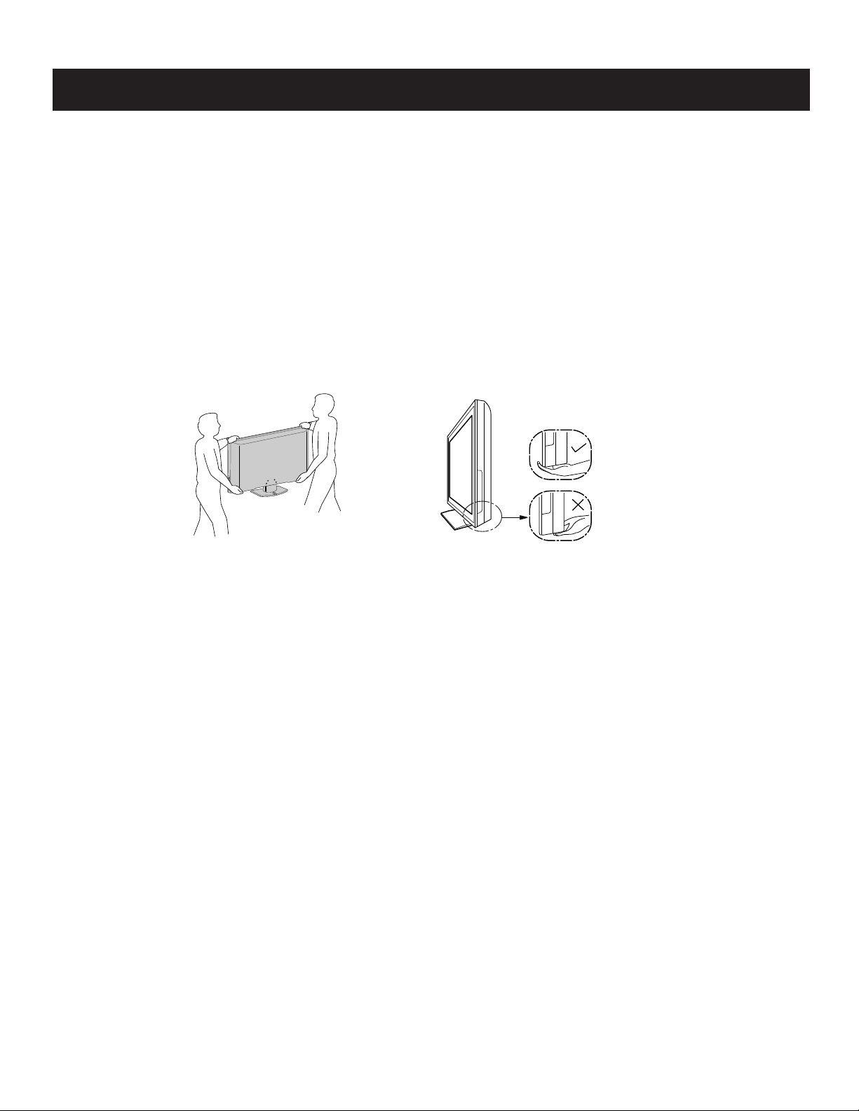
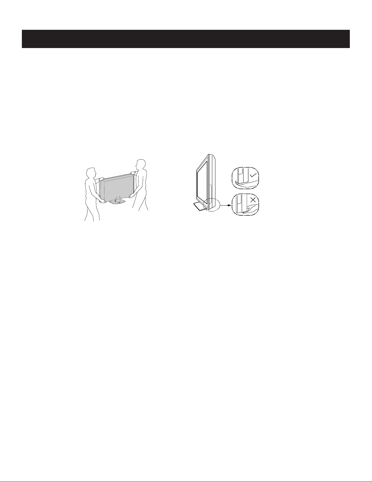
CARRYING THE TV
Be sure to follow these guidelines to protect your property and avoid causing serious injury.
• Carry the TV with an adequqate number of people; larger size TVs require two or more people.
• Correct hand placement while carrying the TV is very important for safety and to avoid damages.
WARNING!!
An isolation transformer should be used during any service to avoid possible shock hazard, because of live chassis. The chassis of this receiver is
directly connected to the ac power line.
! SAFETY-RELATED COMPONENT WARNING!!
Components identifi ed by shading and ! mark on the schematic diagrams, exploded views, and in the parts list are critical for safe operation. Replace
these components with Sony parts whose part numbers appear as shown in this manual or in supplements published by Sony. Circuit adjustments that
are critical for safe operation are identifi ed in this manual. Follow these procedures whenever critical components are replaced or improper operation is
suspected.
KDL-32S5100/40S5100/46S5100
6
KDL-32S5100/40S5100/46S5100
WARNINGS AND CAUTIONS - FRENCH
ATTENTION!!
Ces instructions de service sont à l’usage du personnel de service qualifi é seulement. Pour prévenir le risque de choc électrique, ne pas faire
l’entretien autre que celui contenu dans le Mode d’emploi à moins que vous soyez qualifi é faire ainsi.
POUR TRANSPORTER LE TÉLÉVISEUR
Tenez compte de ce qui suit pendant l’installation du téléviseur :
• Débranchez tous les câbles avant de transporter le téléviseur.
• Transportez le téléviseur avec le nombre de personnes approprié ; un téléviseur de grande
taille doit être transporté par au moins deux personnes.
• Lors du transport du téléviseur, l’emplacement des mains est très important pour votre
sécurité, ainsi que pour éviter de causer des dommages.
ALERTE!!
☛
Afi n d’eviter tout risque d’electrocution provenant d’un chássis sous tension, un transformateur d’isolement doit etre utilisé lors de tout dépannage. Le
chássis de ce récepteur est directement raccordé à l’alimentation du secteur.
! ATTENTION AUX COMPOSANTS RELATIFS A LA SECURITE!!
Les composants identifi es par une trame et par une marque ! sur les schemas de principe, les vues explosees et les listes de pieces sont d’une
importance critique pour la securite du fonctionnement. Ne les remplacer que par des composants Sony dont le numero de piece est indique dans le
present manuel ou dans des supplements publies par Sony. Les reglages de circuit dont l’importance est critique pour la securite du fonctionnement
sont identifi es dans le present manuel. Suivre ces procedures lors de chaque remplacement de composants critiques, ou lorsqu’un mauvais
fonctionnement suspecte.
KDL-32S5100/40S5100/46S5100
7
SAFETY-RELATED COMPONENT WARNING
KDL-32S5100/40S5100/46S5100
There are critical components used in LCD color TVs that are important for safety. These components are identifi ed with shading and
mark on the schematic diagrams and the electrical parts list. It is essential that these critical parts be replaced only with the part number
specifi ed in the electrical parts list to prevent electric shock, fi re, or other hazard.
NOTE: Do not modify the original design without obtaining written permission from the manufacturer or you will void the original parts and
labor guarantee.
!
USE CAUTION WHEN HANDLING THE LCD PANEL
When repairing the LCD panel, be sure you are grounded by using a wrist band.
When installing the LCD panel on a wall, the LCD panel must be secured using the 4 mounting holes on the rear cover.
To avoid damaging the LCD panel:
do not press on the panel or frame edge to avoid the risk of electric shock.
do not scratch or press on the panel with any sharp objects.
do not leave the module in high temperatures or in areas of high humidity for an extended period of time.
do not expose the LCD panel to direct sunlight.
avoid contact with water. It may cause a short circuit within the module.
disconnect the AC adapter when replacing the backlight (CCFL) or inverter circuit.
(High voltage occurs at the inverter circuit at 650Vrms.)
always clean the LCD panel with a soft cloth material.
use care when handling the wires or connectors of the inverter circuit. Damaging the wires may cause a short.
protect the panel from ESD to avoid damaging the electronic circuit (C-MOS).
LEAKAGE CURRENT HOT CHECK CIRCUIT
KDL-32S5100/40S5100/46S5100
8
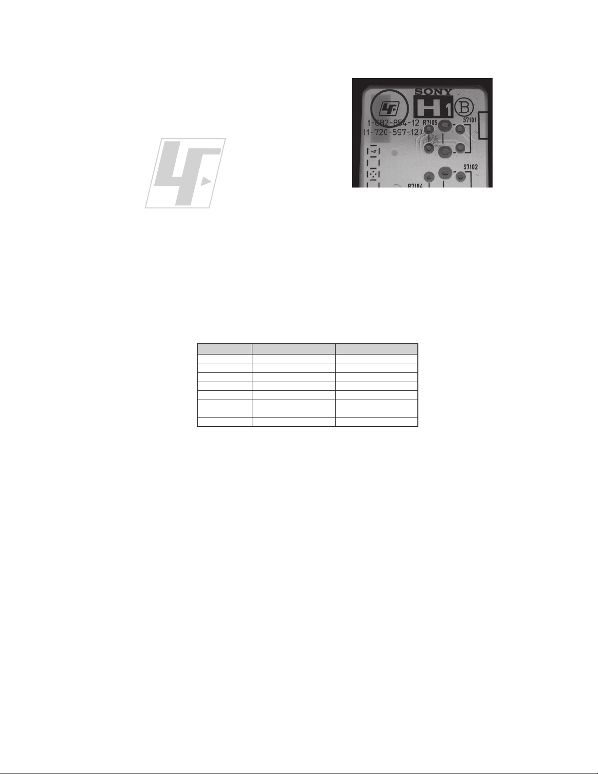
The circuit boards used in these models have been processed using
Lead Free Solder. The boards are identified by the LF logo located
close to the board designation e.g. H1 etc [ see example ]. The
servicing of these boards requires special precautions to be taken as
outlined below.
KDL-32S5100/40S5100/46S5100
example 1
It is strongly recommended to use Lead Free Solder material in order to guarantee optimal quality of new solder joints.
Lead Free Solder is available under the following part numbers :
rebmuntraP retemaiD skrameR
91-500-046-7mm3.0gK52.0
02-500-046-7mm4.0gK05.0
12-500-046-7mm5.0gK05.0
22-500-046-7mm6.0gK52.0
32-500-046-7mm8.0gK00.1
42-500-046-7mm0.1gK00.1
52-500-046-7mm2.1gK00.1
62-500-046-7mm6.1gK00.1
Due to the higher melting point of Lead Free Solder the soldering iron tip temperature needs to be set to 370 degrees centigrade.
This requires soldering equipment capable of accurate temperature control coupled with a good heat recovery characteristics.
For more information on the use of Lead Free Solder, please refer to
http://www.sony-training.com
KDL-32S5100/40S5100/46S5100
9
SAFETY CHECK-OUT
KDL-32S5100/40S5100/46S5100
After correcting the original service problem, perform the following
safety checks before releasing the set to the customer:
1. Check the area of your repair for unsoldered or poorly soldered
connections. Check the entire board surface for solder splashes and
bridges.
2. Check the interboard wiring to ensure that no wires are “pinched” or
touching high-wattage resistors.
3. Check that all control knobs, shields, covers, ground straps, and
mounting hardware have been replaced. Be absolutely certain that
you have replaced all the insulators.
4. Look for unauthorized replacement parts, particularly transistors,
that were installed during a previous repair. Point them out to the
customer and recommend their replacement.
5. Look for parts which, though functioning, show obvious signs of
deterioration. Point them out to the customer and recommend their
replacement.
6. Check the line cords for cracks and abrasion. Recommend the
replacement of any such line cord to the customer.
7. Check the antenna terminals, metal trim, “metallized” knobs, screws,
and all other exposed metal parts for AC leakage. Check leakage as
described below.
The AC leakage from any exposed metal part to earth ground and
from all exposed metal parts to any exposed metal part having a
return to chassis, must not exceed 0.5 mA (500 microamperes).
Leakage current can be measured by any one of three methods.
1. A commercial leakage tester, such as the Simpson 229 or RCA
WT-540A. Follow the manufacturers’ instructions to use these
instructions.
2. A battery-operated AC milliampmeter. The Data Precision 245
digital multimeter is suitable for this job.
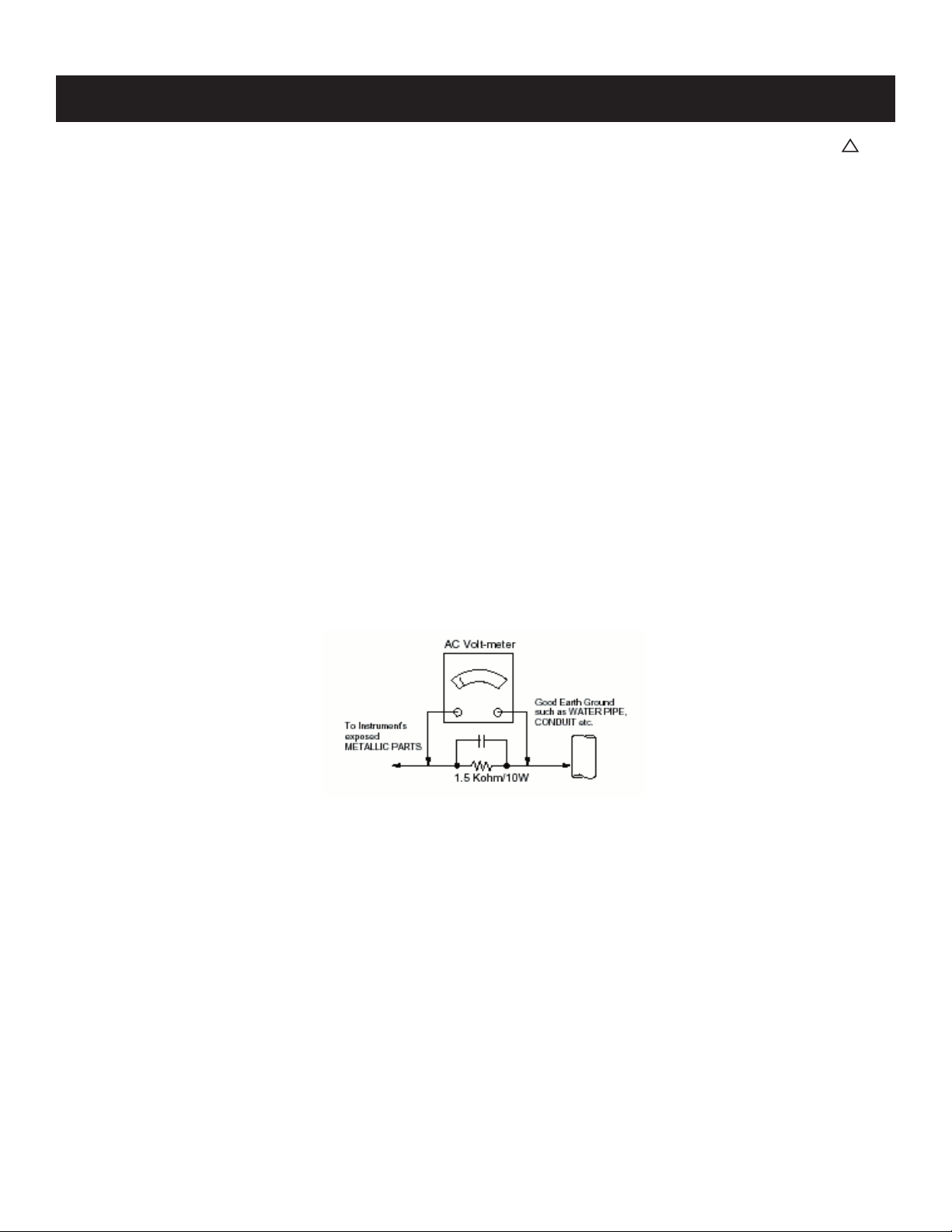
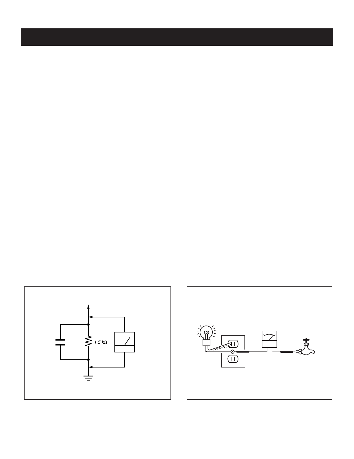
3. Measuring the voltage drop across a resistor by means of a VOM
or battery-operated AC voltmeter. The “limit” indication is 0.75
V, so analog meters must have an accurate low voltage scale.
The Simpson’s 250 and Sanwa SH-63TRD are examples of
passive VOMs that are suitable. Nearly all battery-operated digital
multimeters that have a 2 VAC range are suitable (see Figure A).
How to Find a Good Earth Ground
A cold-water pipe is a guaranteed earth ground; the cover-plate
retaining screw on most AC outlet boxes is also at earth ground. If the
retaining screw is to be used as your earth ground, verify that it is at
ground by measuring the resistance between it and a cold-water pipe
with an ohmmeter. The reading should be zero ohms.
If a cold-water pipe is not accessible, connect a 60- to 100-watt
trouble- light (not a neon lamp) between the hot side of the receptacle
and the retaining screw. Try both slots, if necessary, to locate the hot
side on the line; the lamp should light at normal brilliance if the screw
is at ground potential (see Figure B).
Leakage Test
0.15 F
Figure A. Using an AC voltmeter to check AC leakage. Figure B. Checking for earth ground.
To Exposed Metal
Parts on Set
Earth Ground
AC
Voltmeter
(0.75V)
Trouble Light
AC Outlet Box
Ohmmeter
Cold-water Pipe
KDL-32S5100/40S5100/46S5100
10
KDL-32S5100/40S5100/46S5100
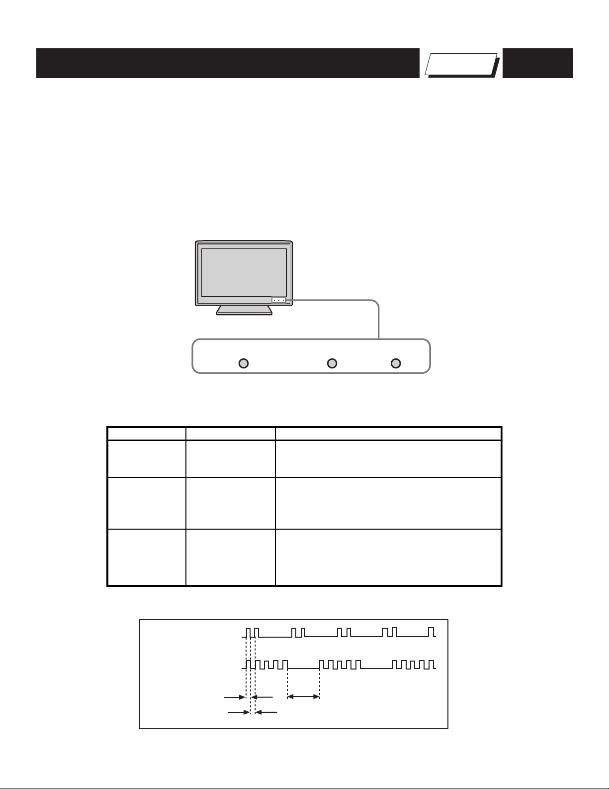
SELF-DIAGNOSTIC FUNCTION
The units in this manual contain a self-diagnostic function. If an error occurs, the STANDBY LED indicator will automatically begin to fl ash. The number
of times the LED fl ashes translates to a probable source of the problem. A defi nition of the STANDBY LED fl ash indicators is listed in the instruction
manual for the user’s knowledge and reference. If an error symptom cannot be reproduced, the Remote Commander can be used to review the failure
occurrence data stored in memory to reveal past problems and how often these problems occur.
1. Diagnostic Test Indicators
When an error occurs, the STANDBY LED indicator will fl ash a set number of times to indicate the possible cause of the problem. If there is more than
one error, the indicator will identify the fi rst of the problem areas.
LED Indicators
☛
PIC OFF / TIMER
STANDBY
POWER
Self Diagnosis
Supported model
Description of LED Indictors
LED LED Type Description
POWER LED
STANDBY LED
PIC OFF/
TIMER
LED
Green LED
Red LED
Green or Orange
LED
2 times
5 times
LED ON 0.3 sec.
LED OFF 0.3 sec.
* Lights up in green when the TV set is turned on.
* Lights up in red when TV is in PC standby mode.
* If LED blinks continuously, this may indicate
that the TV needs servicing.
* Lights up in green when Picture Off is activated.
* Lights up in orange when the timer is set.
When timer is set, this LED remains lit even
when the TV is turned off.
LED OFF
3 sec.
KDL-32S5100/40S5100/46S5100
11

LED Indicators
p
s
KDL-32S5100/40S5100/46S5100
Diagnostic Item
Descri
tion
Main Power 2 times
DC Alert1 3 times
TCON Error 4 times LCD Panel
HDMI 5 times BM3 (Main) Board
Backlight 6 times LCD Panel
Temp 7 times BM3 (Main) Board
HFR Error 8 times LCD Panel
Viewing the Self Check Diagnostic List
1. TV must be in standby mode. (Power off).
2. Press the following buttons on the Remote Commander within a second
of each other:
DISPLAY
The Self Check list displays.
NOTE: This is the same as accessing Service Adjustments.
The
displays.
Channel 5 Volume +
logo displays momentarily, then the Service Mode list
Number of times
STANDBY lamp flashe
TV POWER
.
3. To display the Self Diagnostic list, press
Service/ADC Auto Calibration
Version: ER2.6-C121 DTT: S255.P033.S077
Model: 40S5100
Serial : 8000016
Power on Time: 00000H
Diagnostic and Serial Update
ADC Auto Calibration
Clone User Setting
Direct Log to USB
Factory Default
Change Back Exit
RETURN
4. To exit Service Mode, press .
Possible Location
Power Supply Board
G2BE Board (KDL-32S5100 ONLY)
IP1 Board (KDL-40S5100 ONLY)
IP2 Board (KDL-46S5100 ONLY)
BM3 (Main) Board
Power Supply Board
G2BE Board (KDL-32S5100 ONLY)
IP1 Board (KDL-40S5100 ONLY)
IP2 Board (KDL-46S5100 ONLY)
.
Service Mode/Product Information
Version: ER2.6-C121 DTT: S255.P033.S077
Model: 40S5100
Power on Time: 00000H
Serial :
Diagnostic Information
2-MAIN POWER: 1
3-DC ALERT1: 0
8000016
1 indicates an error was detected
0 indicates no error was detected
4-TCON: 0
5-HDMI:
0
6-Backlight: 0
7-TEMP: 0
8-HFR: 0
101-WDT: 0
Change Back Exit
RETURN
KDL-32S5100/40S5100/46S5100
12
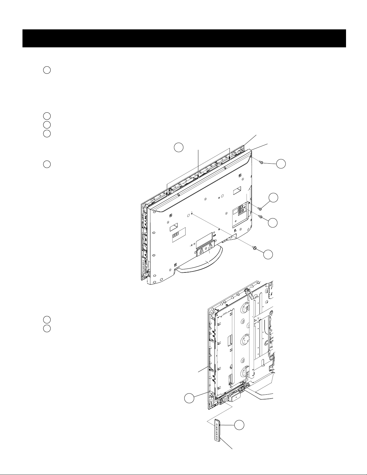
1-1. REAR COVER REMOVAL
1
SC
R
EW
,
+BVTP2 4X16
2
SCRE
W,
+BVTP 3X12 TYPE2
IT
-3
4
SC
R
EW
,
+PSW M4X8
(
32)
SC
R
EW
,
+S
PW M4X12
(
40/46)
Rear Cove
r
Beze
l
Ta
b Inserts
3
SCRE
W,
+BVTP 3X12 TYPE2
IT
-
3
5
Bezel
Switch Unit (Contains HW3 Board)
1
2
1
Remove 15 screws from Rear Cover
(KDL-32S5100 ONLY)
Remove 18 screws from Rear Cover
(KDL-40S5100 ONLY)
Remove 20 screws from Rear Cover
(KDL-46S5100 ONLY)
2
Remove 1 screw from Side Jack position
3
Remove 1 screw from Terminal position
4
Remove 2 screws from Rear Cover
(KDL-32S5100 ONLY)
Remove 4 screws from Rear Cover
(KDL-40/46S5100 ONLY)
5
The Rear Cover is attached to the Bezel Assembly
with three small tabs Use caution when removing
the Rear Cover to avoid damage to these tabs
KDL-32S5100/40S5100/46S5100
SECTION 1: DISASSEMBLY
1-2. SWITCH UNIT REMOVAL
1
Slide out Switch unit from Bezel
2
Disconnect 1 connector from HW3 Board
KDL-32S5100/40S5100/46S5100
13
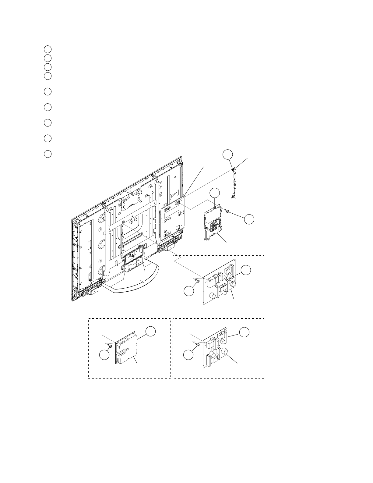
1-3. BM3 BOARD AND POWER BOARD REMOVAL
3 SCREW,
+BVST 3X6
2
1
4
6
5
SCREW,
+BVST 3X6
9
SCREW,
+BVST 3X6
7
SCREW,
+BVST 3X6
Side Jack Cover
BM3 Board
G2BE BOARD
IP2 BOARD
IP1 BOARD
Main Bracket
KDL-40S5100 ONLY
KDL-46S5100 ONL
Y
KDL-32S5100 ONLY
8
1
Unhook Side Jack Cover from Main Bracket
2
Disconnect 5 connectors from BM3 Board
3
Remove 9 screws from BM3 Board
4
Disconnect 5 connectors from IP2 Board
(KDL-46S5100 ONLY)
5
Remove 6 screws from IP2 Board
(KDL-46S5100 ONLY)
6
Disconnect 5 connectors from IP1 Board
(KDL-40S5100 ONLY)
7
Remove 6 screws from IP1 Board
(KDL-40S5100 ONLY)
8
Disconnect 3 connectors from G2BE Board
(KDL-32S5100 ONLY)
9
Remove 6 screws from G2BE Board
(KDL-32S5100 ONLY)
KDL-32S5100/40S5100/46S5100
KDL-32S5100/40S5100/46S5100
14
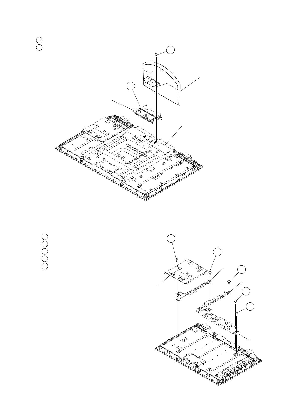
1-4. TABLE-TOP STAND ASSEMBLY AND UNDER COVER REMOVAL
1 SCREW,
+PSW M5X16
2
Table-Top
Stand Assembly
Under Cover
Bottom Frame
1 SCREW,
+BVTP 3X12 TYPE2 IT-3
2
SCREW,
+PSW M4X8
3
SCREW,
+PSW M4X8
5
SCREW,
+PSW M4X8
4
SCREW,
+BVTP2 4X16
Main Bracket
Spine (R)
Bottom Frame
Spine (L)
Remove 4 screws from Table-Top Stand Assembly
1
Remove Under Cover from Bottom Frame
2
KDL-32S5100/40S5100/46S5100
1-5. STRUCTURAL PARTS REMOVAL
1-5-1. KDL-32S5100 ONLY
Remove 1 screw from Main Bracket and Bezel
1
Remove 2 screws from Spine (L)
2
Remove 2 screws from Spine (R)
3
Remove 2 screws from Bottom Frame
4
Remove 2 screws from Bottom Frame
5
KDL-32S5100/40S5100/46S5100
15
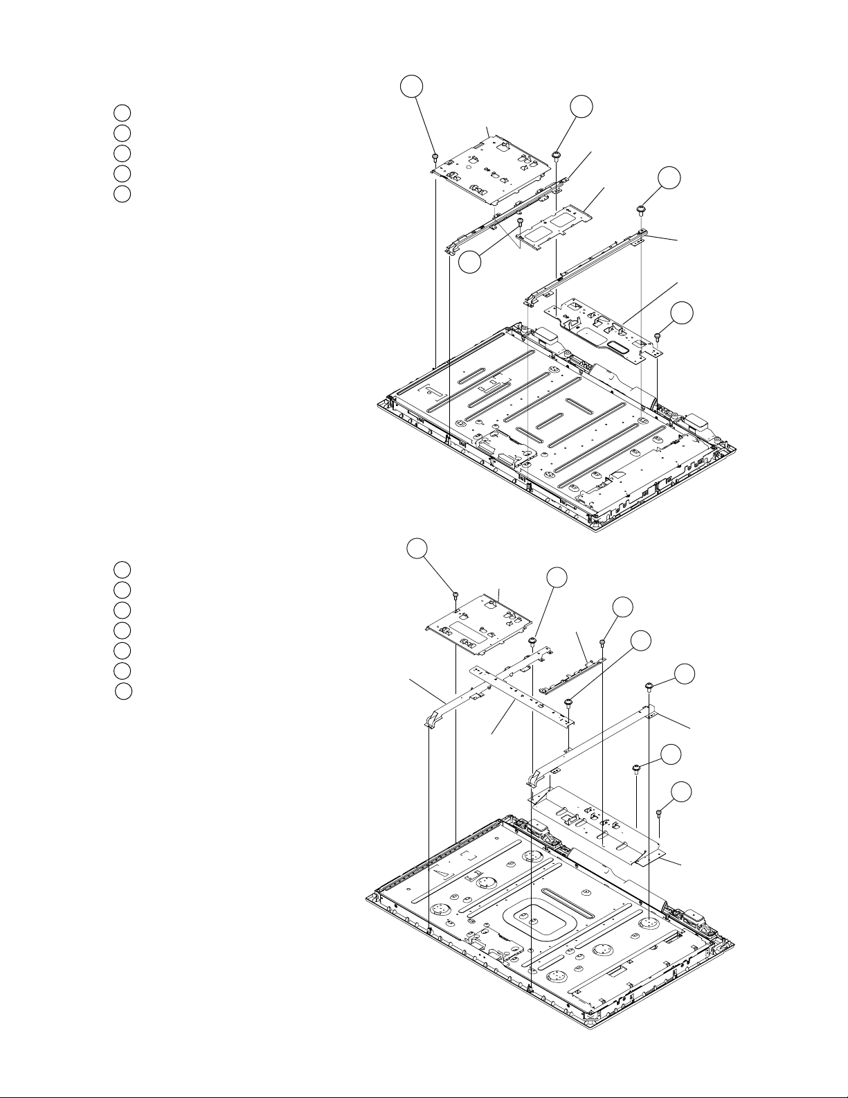
1-5-2. KDL-40S5100 ONLY
1 SCREW,
+BVTP 3X12 TYPE2 IT-3
3 SCREW,
+BVST 3X6
2 SCREW,
+PSW M4X8
4 SCREW,
+PSW M4X
8
Main Bracket
Spine (R)
Bottom Frame
Spine (L)
IP1 Frame
5 SCREW,
+BVTP2 4X16
Main Bracket
Spine (R)
G Frame
Bottom Frame
Spine (L)
Center Frame
1 SCREW,
+BVTP 3X12 TYPE2 IT-3
2 SCREW,
+PSW M5X8
4 SCREW,
+PSW M5X
8
5 SCREW,
+PSW M5X8
7 SCREW,
+PSW M5X
8
3 SCREW,
+BVST 3X6
6 SCREW,
+BVTP2 4X16
KDL-32S5100/40S5100/46S5100
Remove 1 screw from Main Bracket and Bezel
1
Remove 4 screws from Spine (L)
2
Remove 3 screws from IP1 Frame
3
Remove 4 screws from Spine (R)
4
Remove 3 screws from Bottom Frame
5
1-5-3. KDL-46S5100 ONLY
7 Remove 1 screw from Bottom Frame
Remove 1 screw from Main Bracket and Bezel
1
Remove 3 screws from Spine (L)
2
Remove 1 screw from G Frame
3
Remove 2 screws from Center Frame
4
Remove 3 screws from Spine (R)
5
Remove 3 screws from Bottom Frame
6
KDL-32S5100/40S5100/46S5100
16
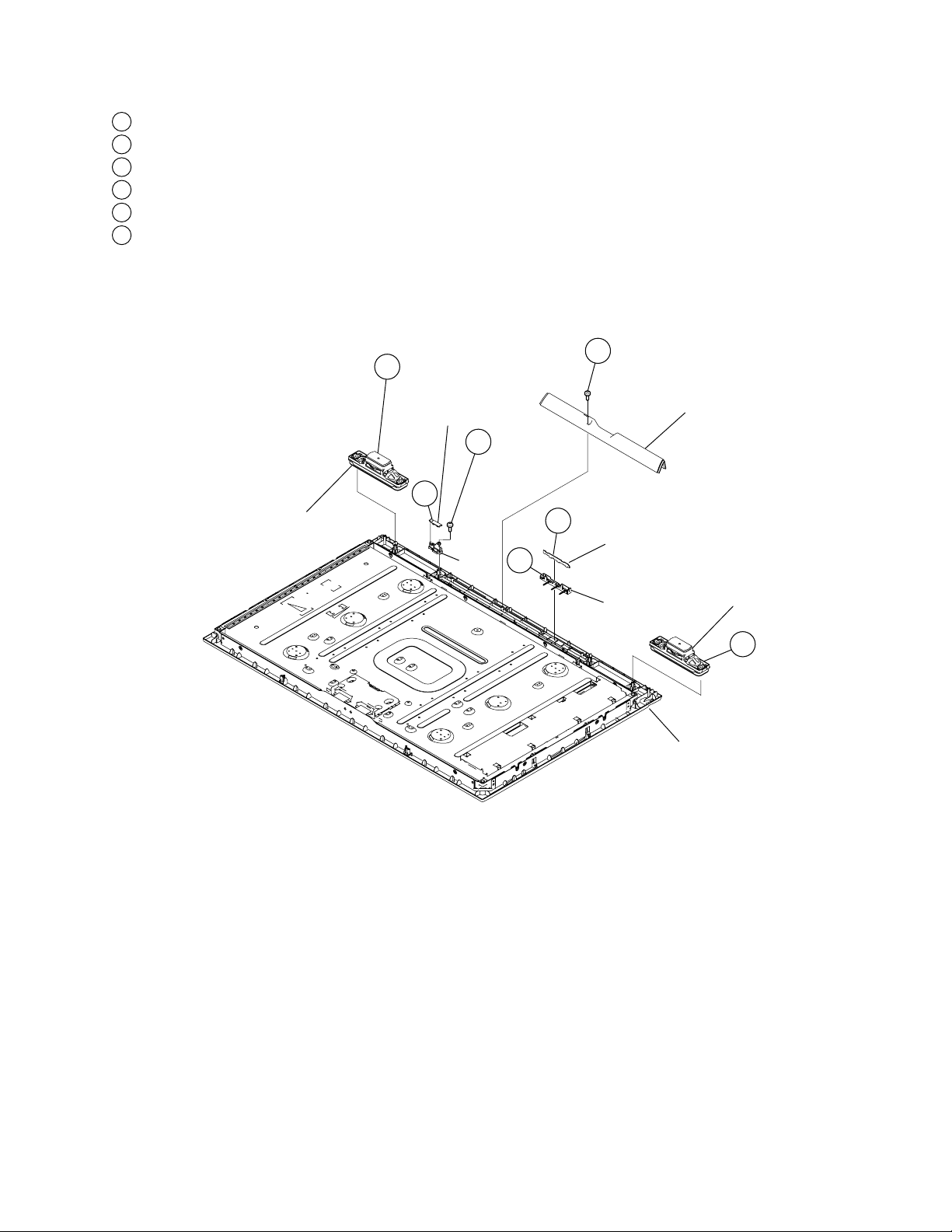
1-6. LOUDSPEAKER, UNDER BAR, IR/LED REMOVAL
Speaker
Speaker
LED Guide
IR
Guide
Under Bar
HSR Board
HLR1 Board
Bezel
1
2 SCREW,
+BVTP2 4X16
1
5
6 SCREW,
+BVTP 3X12
TYPE2 IT-3
4
3
1
Slide out both Speakers from Bezel
2
Remove 1 screw from Under Bar
3
Disconnect 1 connector from HLR1 Board and release from LED Guide
4
Unhook and release LED Guide from Bezel
5
Disconnect 1 connector from HSR Board and release from IR
6
Remove 1 screw and release IR from Bezel
KDL-32S5100/40S5100/46S5100
KDL-32S5100/40S5100/46S5100
17
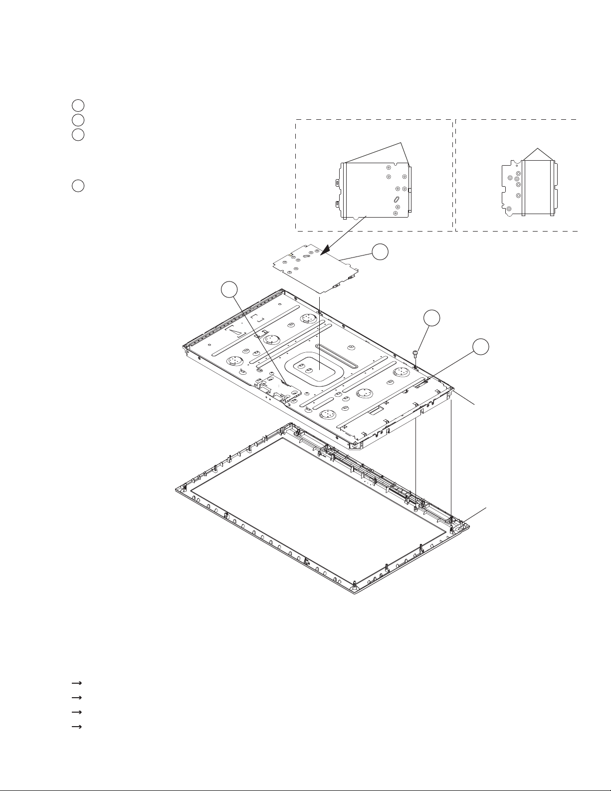
1-7. LCD PANEL REMOVAL
Y
e
☛
CAUTION: When replacing the LCD Panel, you must also replace the Radiation sheet.
For part number information, refer to the Exploded View section of this manual.
1
Remove LVDS connector and LVDS Holder from T-CON and LCD panel
2
Remove 2 screws and release LCD panel from Bezel
3
Disconnect 1 connector from Inverter Board
(KDL-32S5100 ONLY)
Disconnect 2 connectors from Balancer Board
(KDL-40/46S5100 ONLY)
4
Carefully peel off Insulating Sheet from LCD Panel
CAUTION: The LVDS cable can Only be installed
one way
determine which side is attached to the TCON
and which side is attached to the BM3 Board.
. There is colored tape on the cable to
KDL-32S5100/40S5100/46S5100
Insulating Sheet (IP2)
Detail
1
Double Sided Tape
KDL-46S5100 ONLY
4
Insulating Sheet (IP1)
Detail
Double Sided Tap
KDL-40S5100 ONL
2 SCREW,
+BVTP 4X16
3
LCD Panel
Bezel
1-7-1. CLEANING THE LCD PANEL
CAUTION: When cleaning the TV, be sure to unplug the power cord to avoid any chance of electric shock.
Clean the cabinet of the TV with a dry soft cloth.
Wipe the LCD screen gently with a soft cloth.
Stubborn stains may be removed with a cloth slightly moistened with a solution of mild soap and warm water.
If using a chemically pretreated cloth, please follow the instruction provided on the package.
Never use strong solvents such as a thinner, alcohol or benzine for cleaning.
Periodic vacuuming of the ventilation openings is recommended to ensure to proper ventilation.
KDL-32S5100/40S5100/46S5100
18

1-8. INVERTER BOARD REMOVAL (KDL-32S5100 ONLY)
1
2
2
Cover
Balancer Board
LCD Panel
1
Remove 6 screws from Inverter Board Cover
2
Slide out Inverter Boards from Light Sockets
KDL-32S5100/40S5100/46S5100
KDL-32S5100/40S5100/46S5100
19
20
KDL-32S5100/40S5100/46S5100
KDL-32S5100/40S5100/46S5100
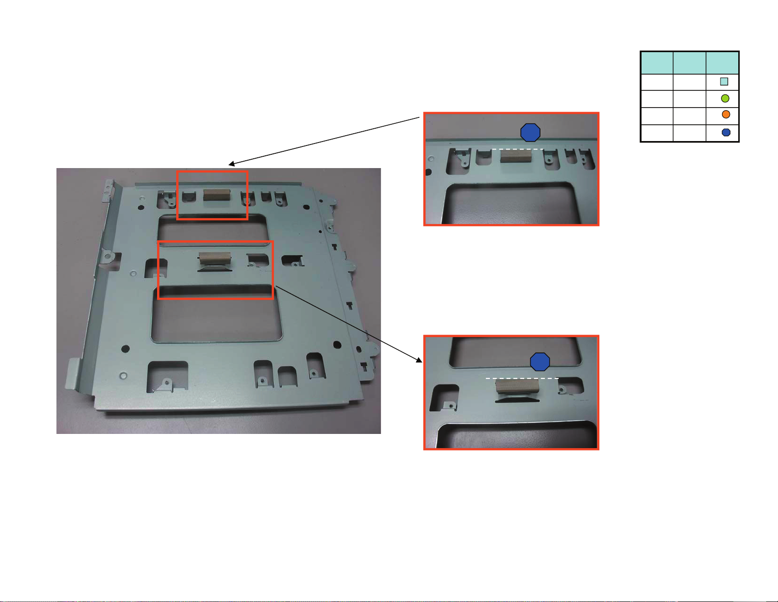
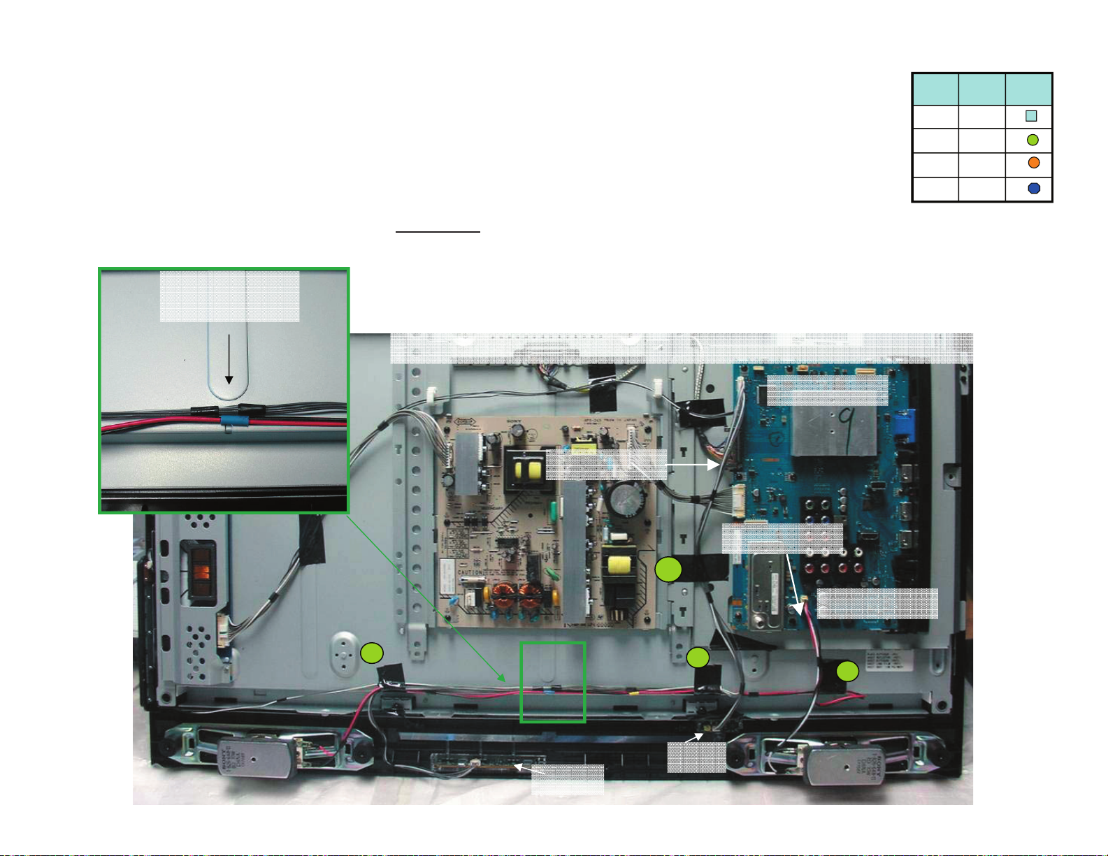
WIRE DRESSING
CONNECTION PLACEMENT
epatbafoC1
)5198.oN(epaT
mm06xmm52
01
teksaG
pmalc T
noitpircseD
4
2
ni lobmyS
gnisserd
tnemucod
ytQ
1
2
epatbafoC1
)5198.oN(epaT
mm06xmm52
01
teksaG
pmalc T
noitpircseD
4
2
ni lobmyS
gnisserd
tnemucod
ytQ
1
1
ot etacidnI epat wolleY
edis nocT lenap
3MB
2019NC
tnioP noituaC
htiw demmaj parT diovA
egde yna hcuot ro latem
elbac eht sserts oN
elbac esool peeK
dna srotcennoc neewteb
sepat
eht revo talf sepaT peeK
elbac
elbaC SDVL 2019NC/3MB ot NOCT
NOCT
mm 09
pmalC T
: noitacidnI
elbac SDVL tcennoC-
dna noC T ot DI epatwolleY-
.)3MB( 2019NC ot edis rehtO
pmalC elbaC tresnI-
eht ni wohs sa sepaT ddA-
erutcip
1
1
decalp eb ot elbac tsrif eht eb llahS SDVL
LVDS Connector
IME yb detseuqer epat
23
epatbafoC1
)5198.oN(epaT
mm06xmm52
01
teksaG
pmalc T
noitpircseD
4
2
ni lobmyS
gnisserd
tnemucod
ytQ
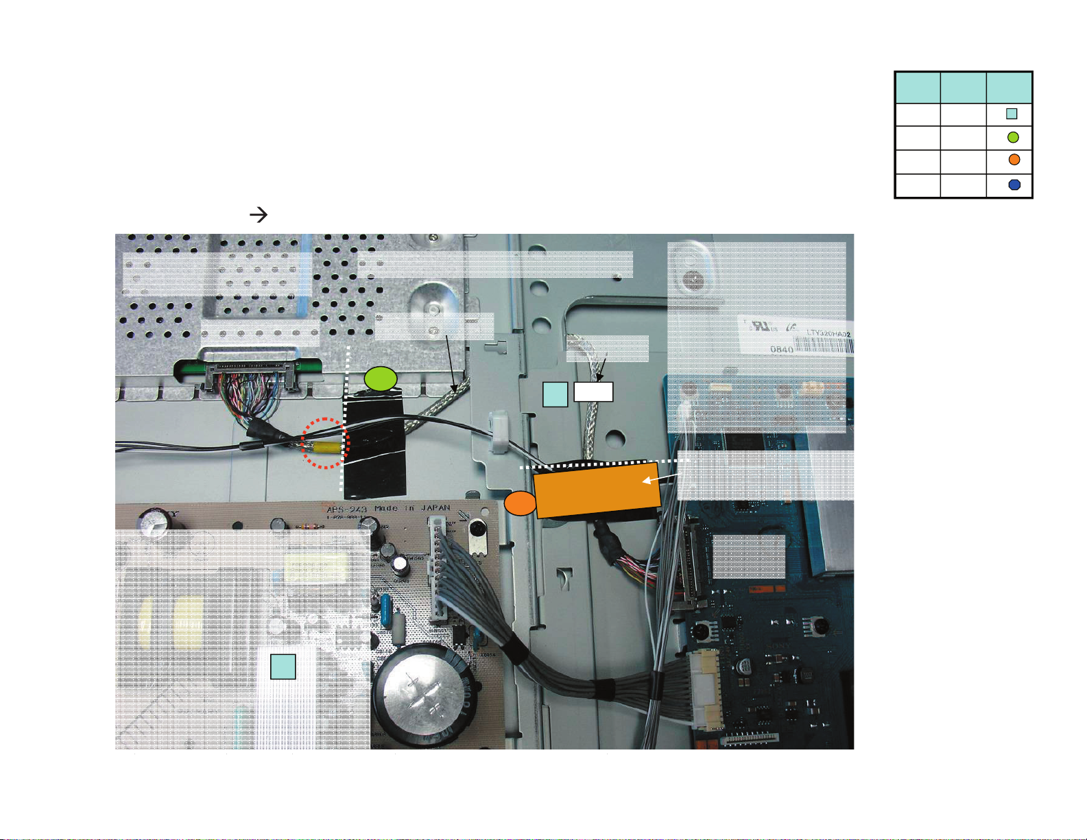
ot 1NC/retrevnI 4001NC/3MB dna 1026NC/2G
4001NC/3MB
1026NC/2G
1NC/retrevnI
2
2
3
Inverter cable
yb gnikat epat ddA
enil tod eht ecnerefer
epatbafoC1
)5198.oN(epaT
mm06xmm52
01
teksaG
pmalc T
noitpircseD
4
2
ni lobmyS
gnisserd
tnemucod
ytQ
3001NC/3MB dna 2026NC/2G
4001NC/3MB
1026NC/2G
25
epatbafoC1
)5198.oN(epaT
mm06xmm52
01
teksaG
pmalc T
noitpircseD
4
2
ni lobmyS
gnisserd
tnemucod
ytQ
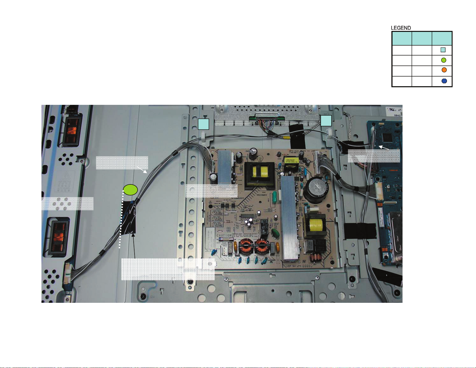
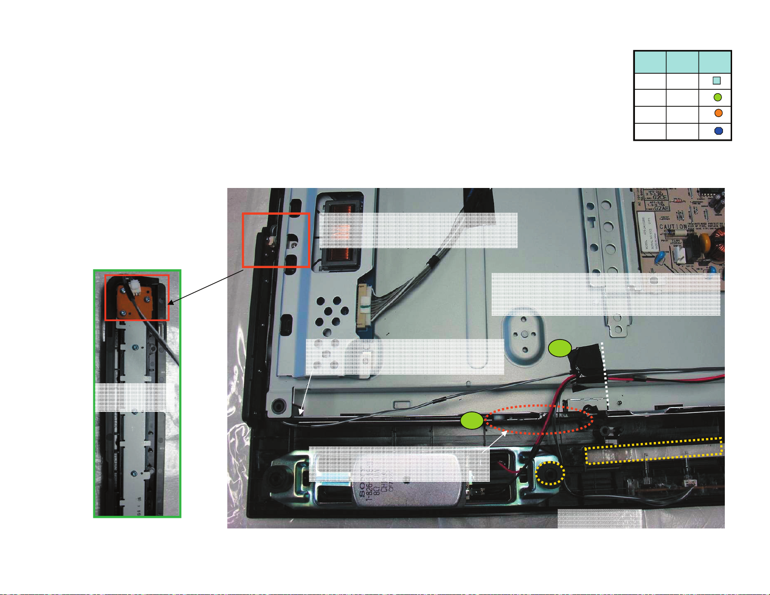
tinuhctiwSdna1RLH,SRHot4003NC/3MB
slanimret srekaepS ot 0002NC/3MB
lenap retneC
ecnerefer
4
5
7
9
:snoitacidnI
tinu hctiwS dna sdraob s’H ot elbac eht tcennoC1-
lanimret srekaeps thgir dna tfel ot elbac eht tcennoC2-
)ecnerefer sa enil dehsad ekat ( lenap fo retnec ta epat eulb etacol ,54 xiffus ssenrah retnec oT-
erutcip ni wohssa )sepat kcalB( sepat htob etacol ,13 xiffus ssenrah retnec oT-
sredils txen eht ni wohs sa sepat ecalP-
RSH
1RLH
0002NC 3MB
4003NC 3MB
1
2
26
epatbafoC1
)5198.oN(epaT
mm06xmm52
01
teksaG
pmalc T
noitpircseD
4
2
ni lobmyS
gnisserd
tnemucod
ytQ
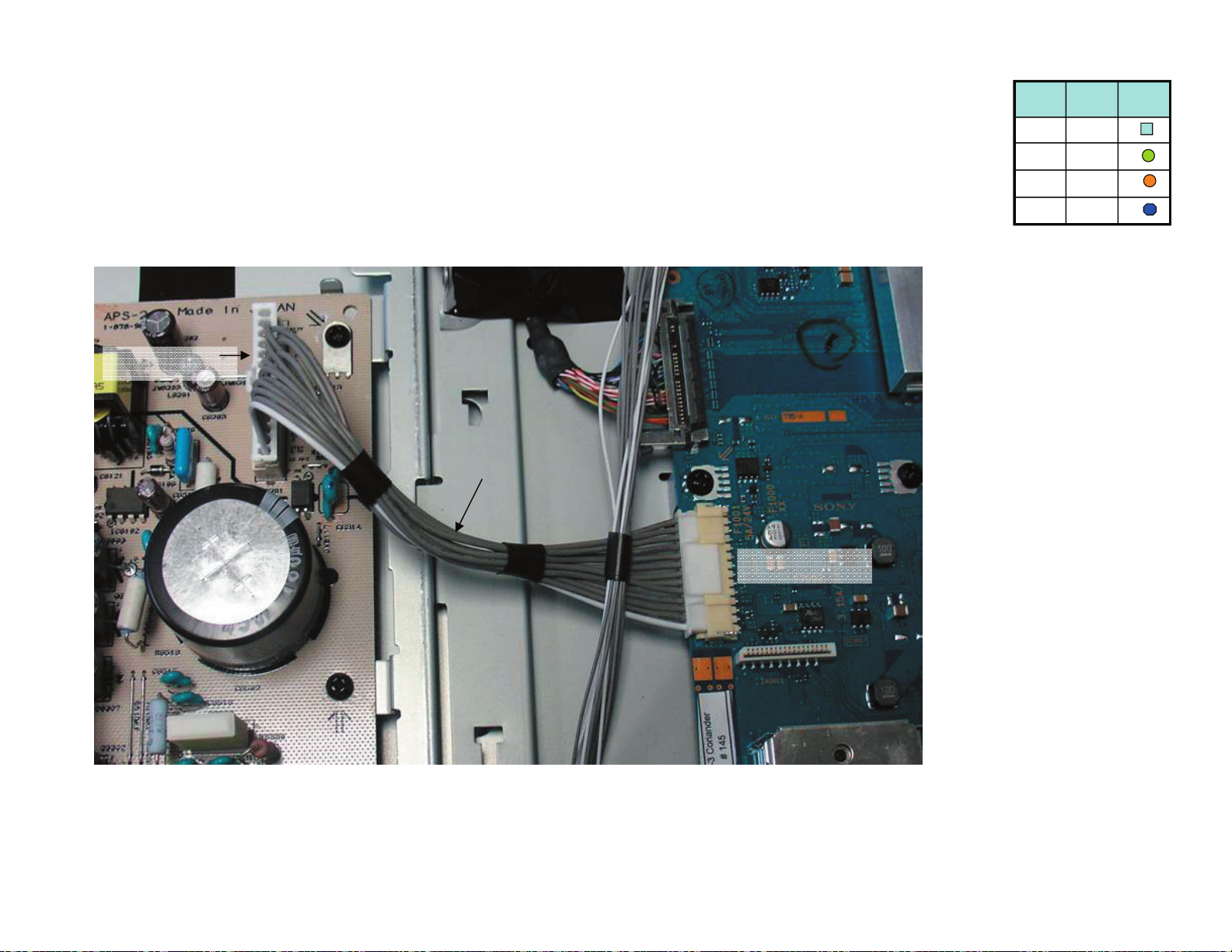
tinu hctiwS dna 1RLH ,RSH ot 4003NC/3MB
slanimret srekaepS ot 0002NC/3MB
tinu hctiwS
4
3
eht ot detcennoc eb llahs elbac ehT
tinu hctiws
revo lanogaid ni epat tresnI
.egde prahs lenap
eht rednu ssorc llahs elbac ehT
egde lenap
103NC 1LRH
:stniop noituaC
elbac yna fo RAELC PEEK wolley ni aerA
eht sserts t’noD :tniop noituaC
si tinu hctiws eht elihw ,elbac
decalp gnieb
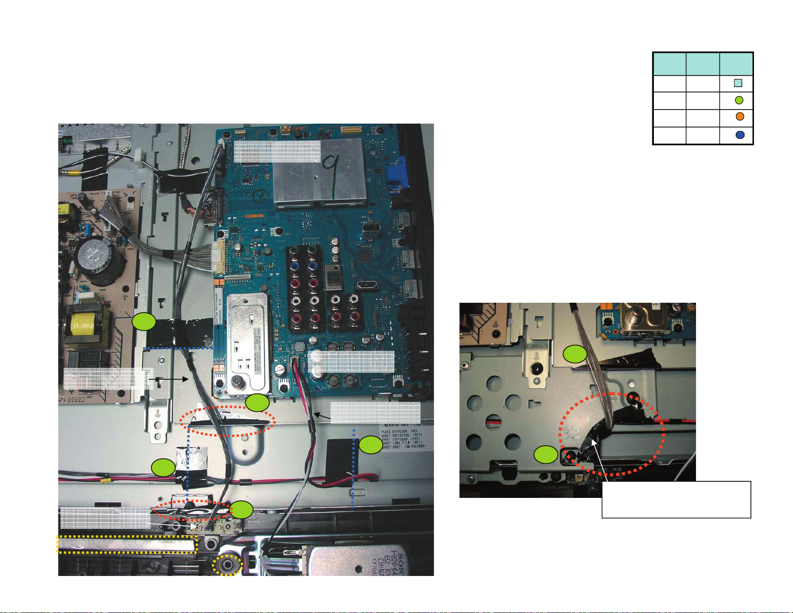
epatbafoC1
)5198.oN(epaT
mm06xmm52
01
teksaG
pmalc T
noitpircseD
4
2
ni lobmyS
gnisserd
tnemucod
ytQ
tinu hctiwS dna 1RLH ,RSH ot 4003NC/3MB
slanimret srekaepS ot 0002NC/3MB
0002NC 3MB
BM3 TO CN3004
4003NC 3MB
104NC/RSH
elbac yna fo RAELC PEEK wolley ni aerA :stniop noituaC
: snoitacidnI
epat ddA- 6 dna 8 lanogaid ni
na lenap eht revo tekcarb niam d
segde prahs
epat tresnI- 7 eht fo tfel eht ot
)enil tod( ecnerefer
epat ddA- 5 dna 9 yb gnikat
enil hsad eht ecnerefer
5
6
7
9
8
01
8
tekcarb eht ni epat tresnI
egde prahs revoc ot
BM3 TO CN2000
28
epatbafoC1
)5198.oN(epaT
mm06xmm52
01
teksaG
pmalc T
noitpircseD
4
2
ni lobmyS
gnisserd
tnemucod
ytQ
3MB wercs ot 2G wercS
G2 to BM3
2G
3MB
29
epatbafoC1
)5198.oN(epaT
mm06xmm52
01
teksaG
pmalc T
noitpircseD
4
2
ni lobmyS
gnisserd
tnemucod
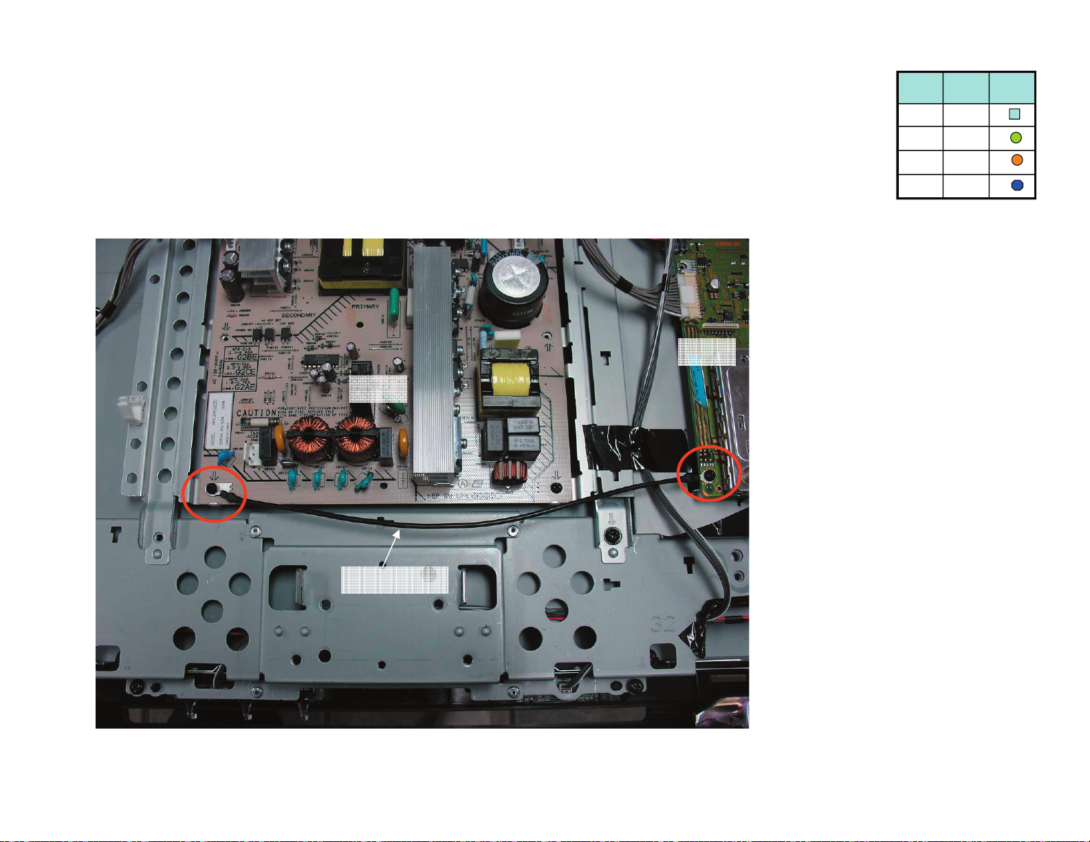
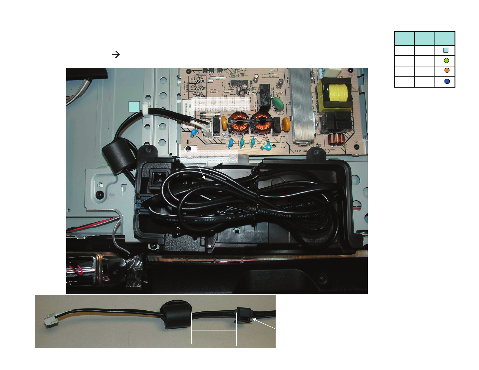
ytQ
droc CA
1016NC/2G
4
1016NC 2G
AC Cord
mm 56
redloH CA
noitisop
KDL-40S5100 ONLY
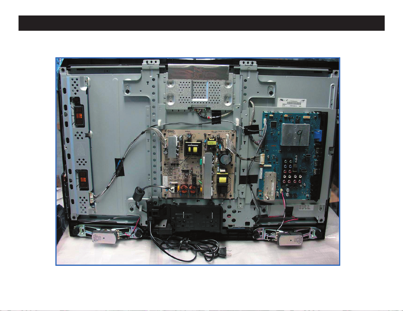
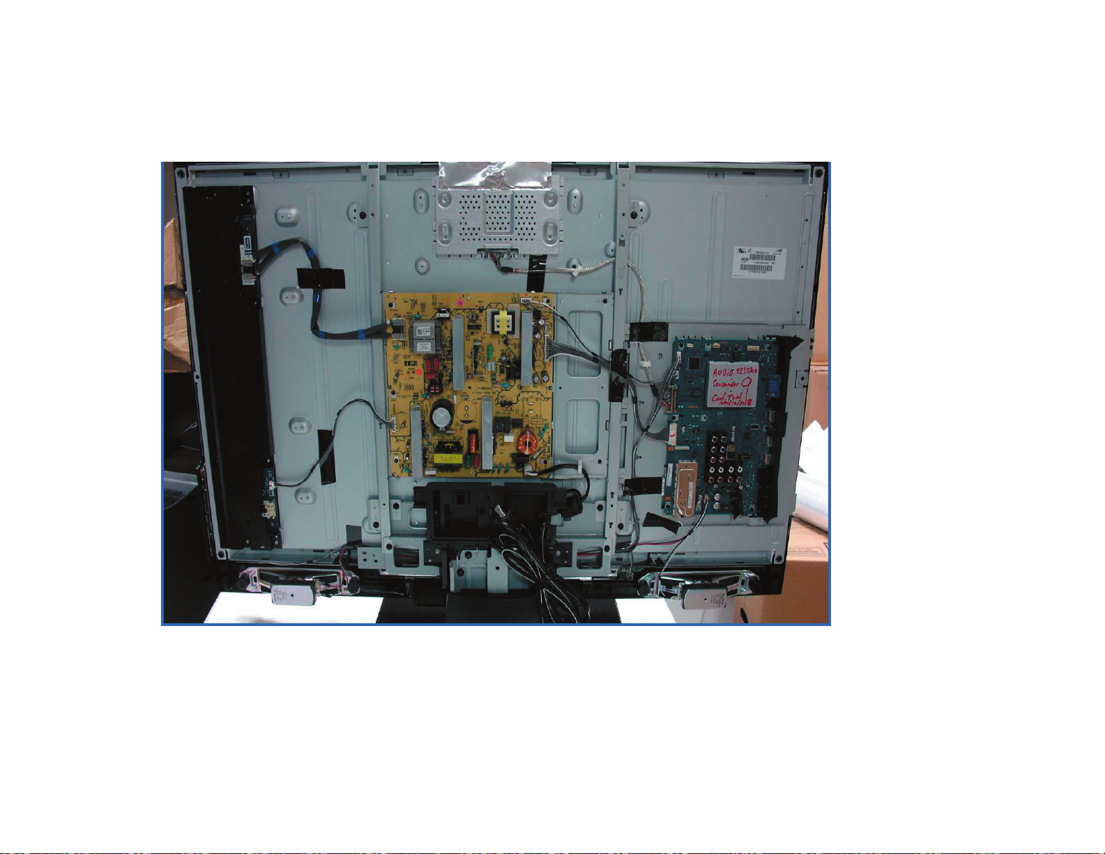
OVERALL ASSEMBLY
KDL-32S5100/40S5100/46S5100
NOTE: THE TAPE COLOR ON THE LVDS CONNECTOR IS TO HELP DETERMINE THE CORRECT
CONNECTION PLACEMENT
KDL-32S5100/40S5100/46S5100
30
 Loading...