

Page 1

HISTORYINFORMATIONFORTHEFOLLOWINGMANUAL:
SERVICE MANUAL
AZ2-F Chassis
ORIGINAL MANUAL ISSUE DATE: 2/2011
Version Date Subject
1.0 2/16/2011 No revisions or updates are applicable at this time.
Segment: 3a-2
LCD Digital Color TV
9-888-405-01
Page 2

SERVICE MANUAL
AZ2-F Chassis
Segment: 3a-2
Self Diagnosis
Supported model
KDL-40EX725
LCD Digital Color TV
9-888-405-01
Page 3

MODELLIST
MODEL COMMANDER DESTINATION MODEL COMMANDER DESTINATION
KDL-32EX725 RM-YD062 CHILE/PERU
KDL-55EX725 RM-YD062 CHILE/PERU
KDL-32EX725 RM-YD062 VENEZUELA
KDL-40EX725 RM-YD062 CHILE/PERU
KDL-40EX725 RM-YD062 VENEZUELA
KDL-55EX725 RM-YD062 VENEZUELA
9-888-405-01
Page 4

TABLEOFCONTENTS
Section 1 - Safety and Features.................................................1
Warnings and Cautions ..............................................................1
Handling the FFC Connector .....................................................3
Safety-Related Warnings ...........................................................4
Safety Check-Out .......................................................................5
Self Diagnosis Function .............................................................7
Overview ....................................................................................8
Features .....................................................................................8
See It All in 3D ............................................................................. 8
MotionFlow™ XR 240 ................................................................. 8
Navigation Made Easy ................................................................ 8
LightSensor™ Technology .......................................................... 8
X-Reality™ Engine ...................................................................... 8
Presence Sensor
USB Photos, Videos & Music
Edge LED Backlighting ................................................................ 9
Internet Streaming & Connectivity ............................................... 9
Faster Start-Up ............................................................................ 9
BRAVIA® Sync™ Compatible ..................................................... 9
Specications ...........................................................................10
Section 2 - Software Requirements.........................................12
Overview ..................................................................................12
Software Updates for Customers .............................................12
......................................................................... 9
...................................................... 9
Software Updates for Servicers ...............................................13
Software Update Responsibility ............................................... 13
Checking the Software Version ................................................. 14
Examples of Software Correctable Symptoms .......................... 14
Section 3 - Chassis Overview ..................................................15
Overview ..................................................................................15
Overall Circuit Description ........................................................17
Main Board ............................................................................... 17
Tuner ......................................................................................... 17
X-Reality Processor ................................................................... 17
Audio Amplier .......................................................................... 17
Temperature Sensor .................................................................. 17
Power Supply ...........................................................................18
Power Supply for Backlight System .........................................18
LD Board (LED Driver Board) ..................................................18
3D IR Emitter ............................................................................18
Switch Unit ...............................................................................18
Motion Sensor Board ...............................................................18
IR Board ...................................................................................18
LCD Panel Assembly ...............................................................19
T-CON Board ............................................................................. 19
Diagrams .................................................................................. 20
Block Diagram ........................................................................... 20
Connector Diagrams ................................................................. 22
KDL-32EX725/40EX725/55EX725 i
Page 5

TABLE OF CONTENTS
Section 4 - Troubleshooting .....................................................28
Overview ..................................................................................28
Updating the Software ............................................................... 28
Triage Chart .............................................................................29
Protection Shutdown ................................................................30
Standby LED Flash Count ......................................................... 30
Diagnostic Code Descriptions ..................................................34
Viewing the Self Check Diagnostic History ............................... 35
Section 5 - Flow Charts and Diagrams ................................... 36
Overview ..................................................................................36
No Power ................................................................................... 37
Standby LED Blinking ................................................................ 39
No Picture/No Sound ................................................................. 45
TV/Remote Commander Buttons Not Working ......................... 48
Network Not Connecting .......................................................... 50
3D Does not Display .................................................................. 52
Skype Accessory Not Working .................................................. 53
G10A/G4B/G6A/G8A (Power Supply) Board and
BATV (Main) Board Removal .............................................59
KDL-32EX725/40EX725 Only ................................................... 59
KDL-55EX725 Only ................................................................... 60
Panel Brackets and LCD Panel Removal ................................61
Cleaning the LCD Panel ............................................................ 61
Screws .....................................................................................62
Connectors ............................................................................... 62
KDL-32EX725 Only ................................................................... 62
KDL-40EX725 Only ................................................................... 63
KDL-55EX725 Only ................................................................... 63
Accessories and Packaging .....................................................64
Miscellaneous ..........................................................................64
Remote Commander ................................................................ 64
Wire Dressing ...........................................................................65
KDL-32EX725 Only ................................................................... 65
KDL-40EX725 Only ................................................................... 65
KDL-55EX725 Only ................................................................... 65
Section 6 - Disassembly/Part Number Information ............... 55
Section 7 - Service Adjustments .............................................66
Table-Top Stand Assembly Removal ........................................55
Overview ..................................................................................66
Rear Cover and AC Cover Removal ........................................ 56
Updating the Software ..............................................................66
Switch Unit and Speakers Removal ......................................... 57
Accessing Service Adjustment Mode ....................................... 66
LD Board, HEM2 Board, HLR2 Board and
HMS3 Board Removal ........................................................58
Viewing or Changing Service Data ............................................ 67
KDL-32EX725/40EX725/55EX725 ii
Page 6

TABLE OF CONTENTS
Verifying Service Adjustments .................................................. 68
Verifying the Segment Code ...................................................... 68
Verifying the Destination ............................................................ 69
Verifying the Model Name ......................................................... 69
Optional Adjustments ...............................................................70
Setting White Balance Adjustments .......................................... 70
Resetting the TV to Factory Condition .....................................71
Resetting the TV to Factory Condition Using Service Mode ..... 71
Appendix A - Removing the Rear Cover ............................... A-1
Removing the Power Cord from the Rear Cover ................... A-1
KDL-32EX725 ..........................................................................A-1
KDL-40EX725 ..........................................................................A-3
Appendix B - Attaching the Rear Cover ................................B-1
Reattaching the Rear Cover to the Bezel ............................... B-1
KDL-32EX725 ..........................................................................B-1
KDL-40EX725 ..........................................................................B-2
Appendix C - Replacing the LCD Panel ................................ C-1
Removing the LCD Panel from the Bezel ..............................C-1
Reattaching the LCD Panel onto the Bezel ............................ C-2
Appendix D - Rear Cover Caution ......................................... D-1
Appendix E - Setup Guide ...................................................... E-1
KDL-32EX725/40EX725/55EX725 iii
Page 7

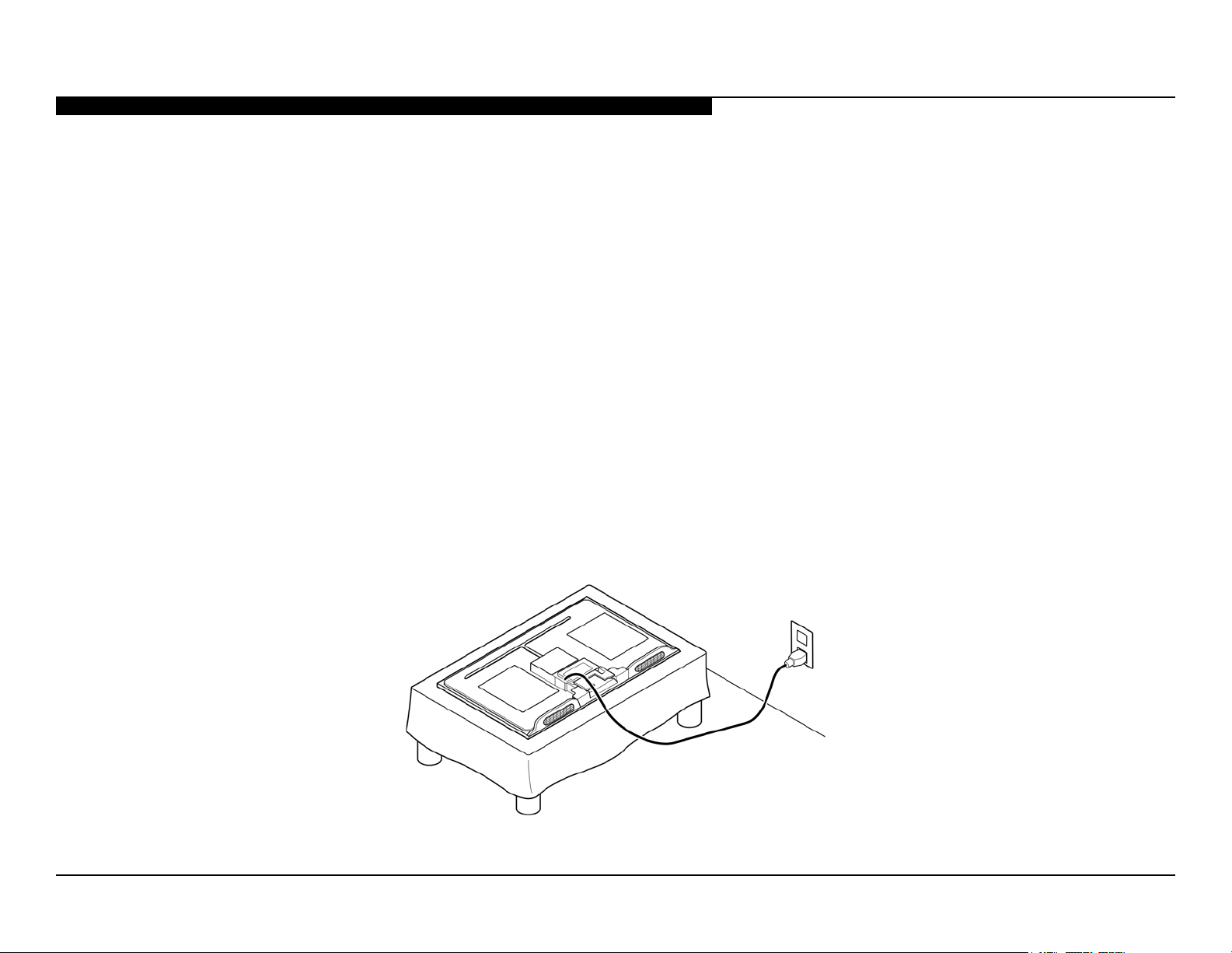
• Disconnect all cables when carrying the TV.
SECTION1-SAFETYANDFEATURES
WARNINGS AND CAUTIONS
CAUTION
These servicing instructions are for use by qualied service personnel only. To reduce the risk of electric shock, do not perform any servicing other
than that contained in the operating instructions unless you are qualied to do so.
CARRYING THE TV
• Carry the TV with the adequate number of people; larger size TVs require two or more people.
• Correct hand placement while carrying the TV is very important for safety and to avoid damage.
WARNING!!
An isolation transformer should be used during any service to avoid possible shock hazard, because of live chassis. The chassis of this receiver is
directly connected to the AC power line.
Components identied by shading and ! mark on the exploded views are critical for safe operation.
Replace all components with Sony parts whose part numbers appear as shown in this manual or in supplements published by Sony. It is essential
that all critical parts be replaced only with the part number specied in this manual to prevent electric shock, re, or other hazard.
Circuit adjustments that are critical for safe operation are identied in this manual.
Follow these procedures whenever critical components are replaced or improper operation is suspected.
NOTE: Do not modify the original design without obtaining written permission from the manufacturer or you will void the original parts and labor
guarantee.
KDL-32EX725/40EX725/55EX725 1
! SAFETY-RELATED COMPONENT WARNING!!
Page 8

SECTION 1 - SAFETY AND FEATURES
CAUTION
W Do Not use paper towels, any type of abrasive pad, rags, rubber or vinyl materials to clean the screen. Using these materials could easily
scratch the screen which may result in permanent damage.
Do Not use any cleaning product containing alkaline/acid cleaner, scouring powder, or volatile solvent, such as alcohol, ammonia,
W
benzene, thinner or insecticide. Using any of these harsh cleaners may result in permanent damage to the screen.
W Do Not spray water or detergent directly onto the TV screen . If liquid drips into the bottom of the screen it may cause a failure.
CLEANING THE LCD PANEL
CAUTION: When cleaning the TV, be sure to unplug the power cord to avoid any chance of electric shock.
Clean the cabinet of the TV with a dry soft cloth.
Wipe the LCD screen gently with a soft cloth.
Stubborn stains may be removed with a cloth slightly moistened with a solution of mild soap and warm water.
R
R If using a chemically pretreated cloth, please follow the instruction provided on the package.
R Never use strong solvents such as a thinner, alcohol or benzine for cleaning.
R Periodic vacuuming of the ventilation openings is recommended to ensure to proper ventilation.
KDL-32EX725/40EX725/55EX725 2
Page 9

SECTION 1 - SAFETY AND FEATURES
Correct Incorrect
DISCONNECTING THE FFC CONNECTOR CONNECTING THE FFC CONNECTOR
HANDLING THE FFC CONNECTOR
1. Gently press down on the release tab of the connector slot.
2. Holding onto the reinforcement tab of the FFC connector,
pull out the connector while continuing to hold down
the release tab of the connector slot.
(See caution below.)
Use the
2
Use caution when you connecting or removing the FFC connector.
Remove the connector by the reinforcement tab only.
tab to
remove
connector.
Press down
Main Board
1. Holding onto the reinforcement tab,
insert the FFC connector into the connector slot.
Use the
tab to
insert
connector.
Main Board
CAUTION: The FFC connector can be inserted into the Main Board upside down.
If it is inserted upside down, the pins on the FFC connector
will short-circuit and damage the board.
Reinforcement tab shows
Terminal side shows
Inserted Correctly Inserted Incorrectly
KDL-32EX725/40EX725/55EX725 3
Page 10
SECTION 1 - SAFETY AND FEATURES
SAFETY-RELATED WARNINGS
USE CAUTION WHEN HANDLING THE LCD PANEL
When repairing the LCD panel, be sure you are grounded by using a wrist band.
When installing the LCD panel on a wall, the LCD panel must be secured using the 4 mounting holes on the rear cover.
1. Do not press on the panel or frame edge to avoid the risk of electric shock.
2. Do not scratch or press on the panel with any sharp objects.
3. Do not leave the module in high temperatures or in areas of high humidity for an extended period of time.
4. Do not expose the LCD panel to direct sunlight.
5. Avoid contact with water. It may cause a short circuit within the module.
6. Disconnect the AC power when replacing the backlight or inverter circuit.
(High voltage occurs at the inverter circuit at 650Vrms.)
7. Always clean the LCD panel with a soft cloth material.
8. Use care when handling the wires or connectors of the inverter circuit. Damaging the wires may cause a short.
9. Protect the panel from ESD to avoid damaging the electronic circuit (C-MOS).
10. During the repair, DO NOT leave the Power On for more than 1 hour while the TV is face down on a cloth.
KDL-32EX725/40EX725/55EX725 4
Page 11

SECTION 1 - SAFETY AND FEATURES
SAFETY CHECK-OUT
After correcting the original service problem, perform the following safety checks before releasing the set to the customer:
1. Check the area of your repair for unsoldered or poorly soldered connections. Check the entire board surface for solder
splashes and bridges.
2. Check the interboard wiring to ensure that no wires are “pinched” or touching high-wattage resistors.
3. Check that all control knobs, shields, covers, ground straps, and mounting hardware have been replaced. Be absolutely
certain that you have replaced all the insulators.
4. Look for unauthorized replacement parts, particularly transistors, that were installed during a previous repair. Point them out
to the customer and recommend their replacement.
5. Look for parts which, though functioning, show obvious signs of deterioration. Point them out to the customer and
recommend their replacement.
6. Check the line cords for cracks and abrasion. Recommend the replacement of any such line cord to the customer.
7. Check the antenna terminals, metal trim, “metallized” knobs, screws, and all other exposed metal parts for AC leakage.
Check leakage as described below.
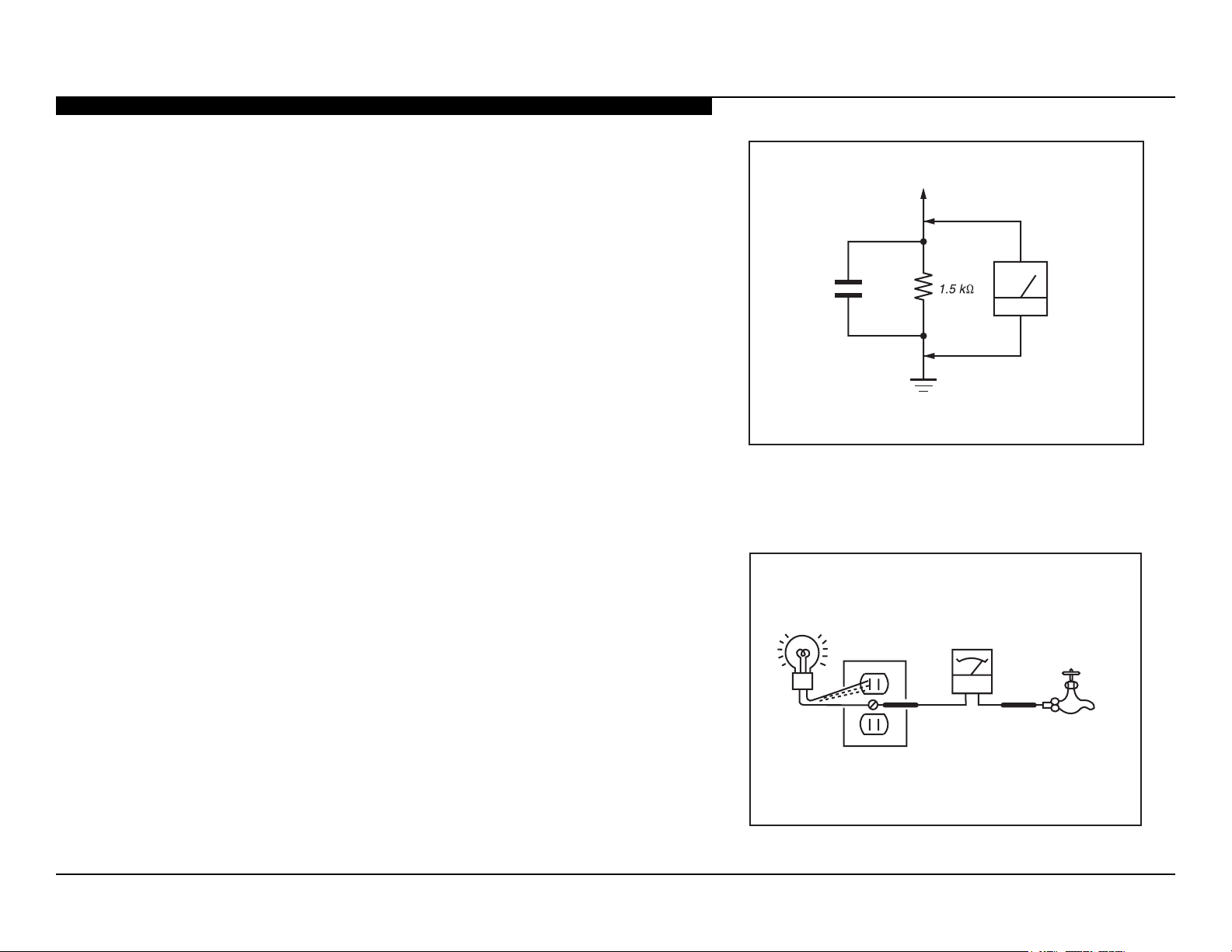
KDL-32EX725/40EX725/55EX725 5
Page 12
SECTION 1 - SAFETY AND FEATURES
Trouble Light
AC Outlet Box
Ohmmeter
Cold-water Pipe
To Exposed Metal
Parts on Set
0.15 µF
Earth Ground
AC
Voltmete
r
(0.75V)
LEAKAGE TEST
The AC leakage from any exposed metal part to earth ground and from all exposed
metal parts to any exposed metal part having a return to chassis, must not exceed
0.5 mA(500 microamperes). Leakage current can be measured by any one of three
methods.
1. A commercial leakage tester, such as the Simpson 229 or RCA
WT-540A. Follow the manufacturers’ instructions to use these
instructions.
2. A battery-operated AC milliampmeter. The Data Precision 245 digital
multimeter is suitable for this job.
3. Measuring the voltage drop across a resistor by means of a VOM
or battery-operated AC voltmeter. The “limit” indication is 0.75 V, so
analog meters must have an accurate low voltage scale.
4. The Simpson’s 250 and Sanwa SH-63TRD are examples of
passive VOMs that are suitable. Nearly all battery-operated digital
multimeters that have a 2 VAC range are suitable (see Figure A).
Figure A. Using an AC voltmeter to check AC leakage.
HOW TO FIND A GOOD EARTH GROUND
A cold-water pipe is a guaranteed earth ground; the cover-plate retaining screw on
most AC outlet boxes is also at earth ground.
If the retaining screw is to be used as your earth ground, verify that it is at ground
by measuring the resistance between it and a cold-water pipe with an ohmmeter.
The reading should be zero ohms.
If a cold-water pipe is not accessible, connect a 60-to 100-watt trouble-light (not a
neon lamp) between the hot side of the receptacle and the retaining screw. Try both
slots, if necessary, to locate the hot side on the line; the lamp should light at normal
brilliance if the screw is at ground potential (see Figure B).
KDL-32EX725/40EX725/55EX725 6
Figure B. Checking for earth ground.
Page 13

Self Diagnosis
Supported model
SECTION 1 - SAFETY AND FEATURES
SELF DIAGNOSIS FUNCTION
The TVs in this manual contain a self-diagnostic function. If an error occurs, the standby LED will automatically begin to ash. The number of
times the LED ashes translates to a probable source of the problem. A denition of the standby LED ash indicator is listed in the Operating
Instruction manual for the user’s reference.
If an error symptom cannot be reproduced, the remote commander can be used to review the failure occurrence data stored in memory to reveal
past problems and how often these problems occur.
For complete information, refer to “Section 4 - Troubleshooting” on page 28.
KDL-32EX725/40EX725/55EX725 7
Page 14

SECTION 1 - SAFETY AND FEATURES
OVERVIEW
The AZ2-F chassis is one of several designs for the 2011 model line
of Sony Bravia® LCD televisions. This manual covers the following
models:
KDL-32EX725
KDL-40EX725
KDL-55EX725
FEATURES
Several new features are introduced in this chassis model lineup
along with some carryovers from the previous year.
SEE IT ALL IN 3D
Enjoy incredible depth and a sharp, Full HD 1080p picture from the
leader in 3D technology. (3D Active Glasses required, sold separately)
MOTIONFLOW™ XR 240
See smooth and precise detail during fast-action scenes. Sony’s
Motionow XR 240 technology for fast action movies and sports by
reducing blur caused by quick camera movements, enhancing image
sharpness, and overall creates a clearer picture.
NAVIGATION MADE EASY
Enjoy an easy-to-use menu that allows you to navigate additional
content or adjust the picture settings while watching your favorite
program.
LIGHTSENSOR™ TECHNOLOGY
Enjoy customized picture brightness and save energy without lifting
a nger. The built-in Light Sensor automatically adjusts the picture
brightness based on the amount of light in the room.
X-REALITY™ ENGINE
Enjoy a vivid, lifelike picture experience. Sony’s X-Reality engine
brings out the best by analyzing each scene so you see sharpened
images, and amazing contrast detail.
KDL-32EX725/40EX725/55EX725 8
Page 15

SECTION 1 - SAFETY AND FEATURES
PRESENCE SENSOR
Save energy when you’re not around. The television’s built-in motion
sensor has the ability to scan the room and detect movement. If the
sensor detects no movement it automatically turns off the picture
leaving only sound. After more time and no movement, the TV turns
itself off minimizing any unnecessary power draw.
USB PHOTOS, VIDEOS & MUSIC
Share your photos on the big screen or listen to your favorite music.
Simply connect your digital camera, USB-enabled MP3 player, or
USB storage device directly to your HDTV’s USB input.
EDGE LED BACKLIGHTING
Experience the next level of picture quality and contrast with Sony’s
Edge LED Backlight technology. This technology sharpens image
contrast giving an amazingly crisp picture you can see. The ultra-thin
backlight system allows for a slimmer, sleeker design.
INTERNET STREAMING & CONNECTIVITY
Internet Streaming: Internet favorites now streaming on your
television. In addition to Qriocity™, watch hit movies with Netix®,
popular TV shows on Hulu Plus™ or user-generated video on
Skype™ Ready:Connect to friends and family all over the globe with
Internet voice and video calls using your TV. Make free video Skypeto-Skype calls and low-cost Skype-to-phone calls with a Sony®
compact microphone/camera (required, sold separately).
Wi-Fi® Ready:Going wireless is easy with the UWA-BR100 Wi-Fi®
adapter (sold separately). Just plug it in and get ready to stream
movies, photos, music and videos straight to your TV from the Internet
or your home network.
DLNA® Streaming:Access and share photos, videos and music on
your TV by streaming them from compatible DLNA® device like your
PC or Playstation®3 system.
2
FASTER START-UP
Quick Start & Viewing feature enables this Sony television to go from
‘OFF’ to ‘ON’ 2-3 times faster than previous Sony televisions.
BRAVIA® SYNC™ COMPATIBLE
Conveniently operate and control other BRAVIA® Sync™ compatible
devices - including BRAVIA® HDTVs, Blu-ray Disc™ Players,
surround sound systems, Handycam® camcorders and Cyber-shot®
digital still cameras, all with one remote control.
YouTube™. You can even listen to personalized music on Pandora®.
Enjoy the widest selection of internet content at your ngertips.
KDL-32EX725/40EX725/55EX725 9
Page 16

SECTION 1 - SAFETY AND FEATURES
System
Checking the accessories
SPECIFICATIONS
Television system Analog: NTSC 3.58/ PAL-M / PAL-N
Channel coverage VHF: 2-13, UHF: 14-69
Panel system LCD (Liquid Crystal Display) Panel
Speaker output 10 W + 10 W
Input/Output jacks
CABLE/ANTENNA 75-ohm external terminal for RF inputs
VIDEO IN 1/2 VIDEO / AUDIO
COMPONENT IN YP
HDMI IN 1/2/3/4 HDMI: Video: 480i, 480p, 576i, 576p, 720p, 720/24p/30p, 1080i, 1080p, 1080/24p/30p
AUDIO OUT/Headphones 500 mVrms (typical)
DIGITAL AUDIO OUT
(OPTICAL)
PC/HDMI 4 AUDIO IN Stereo mini jack
Digital: SBTVD
CATV (Analog): 1-135
BPR (Component Video)
Signal format: 480i, 480p, 576i, 576p,720p, 1080i, 1080p
AUDIO
HDMI:
Analog audio input (minijack) (HDMI IN 4 only)
ARC (Audio Return Channel) (HDMI IN 1 only)
Stereo mini jack
PCM/Dolby Digital optical signal
network environment. 10BASE-T/100BASE-TX communication rate and communication
quality are not guaranteed for this TV.)
Audio: Two channel linear PCM 32, 44.1 and 48 kHz, 16, 20 and 24 bits, Dolby Digital
BGR golana ,nip-51 bus-DNI CP
nnoC( rotcennoc XT-ESAB001/T-ESAB01NAL ection speed may differ depending on the
.tamrof detroppus rof launaM-i eht ot refeRANLD/BSU
Model name KDL- 55EX72x 40EX72x 32EX72x
Power and others
Power requirement 110-240 V AC, 50/60 Hz
Power consumption
in use
Screen size (cm)
(measured diagonally) (inches)
Speaker
Full range (mm)
Dimensions with stand (mm) 1,269 × 799 ×
without stand (mm) 1,269 × 769 ×
wall-mount hole pattern
wall-mount screw size
Mass with stand (kg) 25.4 14.4 10.4
without stand (kg) 20.2 11.2 7.9
Supplied accessories See “Checking the accessories”.
Optional accessories Connecting cables
Operating temperature 0 °C - 40 °C
Remote control (1)
(mm)
(mm)
*1
166 W 110 W 90 W
138.8
54.6
(55 class)
30 × 150 (2)
315
41
300 × 300
M6 (length: refer to Setup Guide.)
Support Belt Kit
Wall-Mount Bracket: SU-WL500
3D Glasses:
TDG-BR250/TDG-BR200/TDG-BR100/TDG-BR50
USB Wireless LAN Adapter
101.6
40
943 × 616 ×
250
943 × 586 × 42943 × 588 ×
W 3.0 naht sseLybdnats ni
80.1
31.5
(32 class)
943 × 604 ×
254
45
Size AAA batteries (2)
Table-Top Stand (1)
*2
Fixing screws for Table-Top Stand
(M5 × 16) (3)
Assembling screws for Table-Top
Stand (M6 × 14) (4) (for KDL-55EX72x)
Assembling screws for Table-Top
Stand (M6 × 14) (3) (for KDL-40/32EX72x)
*1Please refer to the model name printed on the
remote control.
*2Assembling the Table-Top Stand is required.
Refer to the supplied Table-Top Stand leaflet
to assemble the Table-Top Stand.
)lacitrev( senil 080,1 × )latnoziroh( stod 029,1 noituloser yalpsiD
)2( 001 × 03
002 × 002
KDL-32EX725/40EX725/55EX725 10
Page 17

SECTION 1 - SAFETY AND FEATURES
Información de licencias
Macintosh es una marca comercial de Apple Inc., registrada en EE. UU. y otros países.
HDMI, el logotipo de HDMI y High-Definition Multimedia Interface son marcas comerciales o marcas comerciales registradas de HDMI
Licensing, LLC. en EE. UU. y en otros países.
Fergason Patent Properties, LLC:
Nº de patente de EE. UU. 5.717.422
Nº de patente de EE. UU. 6.816.141
Fabricado bajo licencia de Dolby Laboratories. Dolby y el símbolo de la doble D son marcas comerciales de Dolby Laboratories.
Blu-ray Disc es una marca comercial.
“BRAVIA” y , S-Force, Motionflow, BRAVIA Sync y son marcas comerciales o marcas registradas de Sony Corporation.
“PlayStation” es una marca comercial registrada y “PS3” es una marca comercial de Sony Computer Entertainment Inc.
®
, el logotipo de DLNA y DLNA CERTIFIED® son marcas comerciales, marcas de servicio o marcas de certificación de Digital Living
DLNA
Network Alliance.
TrackID is a trademark or registered trademark of Sony Ericsson Mobile Communications AB.
Music and video recognition technology and related data are provided by Gracenot e
technology and related content delivery. For more information, please visit www.gracenote.com.
CD, DVD, Blu-ray Disc, and music and video-related data from Gracenote, Inc., copyri ght © 2000-present Gracenote. Gracenote Software,
copyright © 2000-present Gracenote. One or more patents owned by Gracenote apply to this product and service. See the Gracenote website for
a nonexhaustive list of applicable Gracenote patents. Gracenote, CDDB, MusicID, MediaVOCS, the Gracenote logo and logotype, and the
“Powered by Gracenote” logo are either registered trademarks or trademarks of Gracenote in the United States and/or other countries.
®
. Gracenote is the industry standard in music recognition
KDL-32EX725/40EX725/55EX725 11
Page 18

SECTION2-SOFTWAREREQUIREMENTS
OVERVIEW
There are 2 reasons for updating the software on the TVs.
● Software updates for customers
These updates are for enhancements or improvements that
have been made to the software after the TV was released.
● Software update for servicers
These updates are specically for servicers to use during a
service call.
SOFTWARE UPDATES FOR CUSTOMERS
The subject of software updates is a very important. The televisions
of today have advanced to the point where they are not simply a
television anymore. They are evolving into devices that are designed
to integrate with numerous other devices found in the home. Some
examples are: Portable audio and video devices, still cameras, home
computer networks and accessing the internet to name a few.
Communications with these varying devices requires that the
television be compatible with varying communications protocols.
Although standards are detailed for each of these protocols, the real
world dictates that occasional errors may occur that could prevent
devices from operating or communicating properly.
Keeping the software in the television up-to-date is a procedure that
is normally handled by the owner of the television. Most customers
who own computers and other digital devices are familiar with and are
accustomed to updating the software in their products. If a customer
contacts the Sony Customer Support Center and it is deemed to
be correctable with a software update, the issue is handled at the
customer level.
KDL-32EX725/40EX725/55EX725 12
Page 19

SECTION 2 - SOFTWARE REQUIREMENTS
SOFTWARE UPDATES FOR SERVICERS
The models in this manual utilize a “generic” type Main Board. In
the past, many different Main Boards needed to be stocked due to
differences in software requirements. The software loaded on the
board was specic to the model and its features along with the type
of LCD panel installed during production.
Replacement Main Boards are now stocked with basic software.
Once the replacement board is installed in the unit, the most current
software needs to be installed using a USB thumb drive containing
the necessary software downloaded.
This new method of supplying Main Boards signicantly reduces the
complexity of replacing LCD panels and Main Boards. Information
about the LCD panel is stored on the T-CON circuits. This information
is automatically loaded onto the Main Board when the TV is powered
up. With the correct software version the Main Board and/or the
T-CON or LCD panel can be replaced more efciently.
In addition to software installation, service adjustment information
may need to be modied or veried to complete the service of the
TV. Service adjustment information is covered in “Section 7 - Service
Adjustments” on page 66.
SOFTWARE UPDATE RESPONSIBILITY
Software updates are designed to be performed by the customer.
Warranty repairs in which the issue can be resolved by a software
update are not reimbursable. Most issues involving software
updates are handled by the customer service center and should not
be directed to an authorized service center. It is the responsibility
of the servicer to prevent service calls for issues that involve
software updates. Exceptions to this are certain cases whereby the
customer is unable or unwilling to perform the task. In this situation,
the servicer will be notied and receive the proper authorization for
reimbursement.
It is the servicer’s responsibility, however, to make certain that any
TV requiring a legitimate service is running the latest software
version and to install it if necessary.
KDL-32EX725/40EX725/55EX725 13
Page 20

SECTION 2 - SOFTWARE REQUIREMENTS
CHECKING THE SOFTWARE VERSION
The easiest way to check the version of software that is currently on
the TV is to access the Contact Sony screen by using the customer
menu.
FIGURE 2-1. EXAMPLE OF SOFTWARE VERSION
LOCATED ON THE CONTACT SONY SCREEN
EXAMPLES OF SOFTWARE CORRECTABLE SYMPTOMS
Most symptoms that are correctable by software updates involve
communications issues with other devices or minor glitches in
the operation of a specic function. Below is a list of some of the
symptoms that may be corrected with a software update:
● Fluctuations in picture brightness
● Intermittent picture freezing or noise
● Problems with certain inputs (especially HDMI)
● Intermittent or distorted audio
● Erratic remote control operation
● Unit turns on and off by itself
● Loss of color
● Internet connectivity
● Certain features not working correctly
(photo or video le viewing)
KDL-32EX725/40EX725/55EX725 14
Page 21

SECTION3-CHASSISOVERVIEW
OVERVIEW
The primary circuits contained in the AZ2-F chassis for the consists of a Main Board (designated as the BATV board), Power Supply Board
(designated as the G10A Board for the 32” models, G4B Board for the 40” models, and G6A Board and G8A Board for the 55” models), the Motion
Sensor (HMS3 Board), the IR Board (HLR2 Board), the Switch Unit, and the LCD Panel assembly.
NOTE: For connector part number information, refer to “Connectors” on page 62. For Wire Dressing information, refer to “Wire Dressing” on page 65.
LD
BATV
G10A
SWITCH
UNIT
TCON
HLR2HEM2 HMS3
FIGURE 3-1. BOARD LAYOUT FOR KDL-32EX725
KDL-32EX725/40EX725/55EX725 15
Page 22

SECTION 3 - CHASSIS OVERVIEW
SWITCH
UNIT
SWITCH
UNIT
G4B
BATV
LD
TCON
HLR2HEM2 HMS3
FIGURE 3-2. BOARD LAYOUT FOR KDL-40EX725
G8A
BATV
G6A
LD
TCON
HLR2HEM2 HMS3
FIGURE 3-3. BOARD LAYOUT FOR KDL-55EX725 ONLY
KDL-32EX725/40EX725/55EX725 16
Page 23

SECTION 3 - CHASSIS OVERVIEW
OVERALL CIRCUIT DESCRIPTION
“Figure 3-5. Overall Block Diagram” on page 20 provides an overview
of the AZ2-F chassis. The following are descriptions of the boards
and their functions.
MAIN BOARD
Common to all models the Main Board, designated as the BATV
Board, contains the TV control, video, and audio processing circuitry.
All these functions are accomplished using the X-Reality Processor.
TUNER
The tuner is a combination ATSC/NTSC unit. It can receive traditional
analog NTSC signals via cable or terrestrial along with ATSC digital
signals via terrestrial (8VSB) or cable (64 or 256 QAM).
X-REALITY PROCESSOR
IC9000 performs the majority of the necessary audio and video
processing on the main board.
TV Microprocessor: The CPU internal to the X-Reality processor
controls all aspects of the television functions. Input from the user
along with monitoring of critical circuits is also performed by this
CPU.
HDMI Input and Switching: The customer can select the HDMI1,
HDMI2, HDMI3, HDMI4 input. Each HDMI input contains a common
EDI NVM (not shown) to provide display information data to any
device connected via the HDMI inputs.
LVDS Transmitter: Integrated into IC9000 is a Low Voltage
Differential Signaling (LVDS) transmitter. This circuit converts the
8-bit parallel RGB video information into a set of high speed serial
lines for noise-free transmission to the T-CON circuits located
internally to the LCD panel.
Scan Converter: Signal processing circuit that performs resolution
conversion (aspect ratio) and interlaced to progressive scan (IP)
conversion
AUDIO AMPLIFIER
The audio amplier (IC4601) amplies the digital audio output of the
X-Reality processor and sends it to the speakers.
TEMPERATURE SENSOR
The temperature sensor detects over-temperature conditions on the
Main Board, LCD Panel, or ambient room temperature and sends
the shutdown signal to the processor.
Digital Audio and Video Decoder: The MPEG2 and Digital Dolby
audio streams are received from the tuner for decompression. All
video sources which are not native 1920 X 1080p 60HZ are scaled to
this resolution. Digital audio content is output to the class D amplier
for processing and amplication.
KDL-32EX725/40EX725/55EX725 17
Page 24

SECTION 3 - CHASSIS OVERVIEW
POWER SUPPLY
There are different Power Supply Boards used in the models in this
manual. The type of board depends on the size of LCD panel. They
are:
● G10A-Board (32”)
● G4B-Board (40”)
● G6A-Board (55”)
Note:the G8A in the 55” models is the Power Supply Board
for the Panel LED backlight system.
There are 2 distinct sections on the power supply:
Standby Supply: Continuously operational as long as AC power is
applied, the standby supply generates 3.3V for the circuits requiring
power while the unit is turned off. An unregulated 19V line is present
to provide power to the main relay, PFC and main power supply at
turn-on.
Main Supply: Once the power supply receives a power-on command
from the CPU on the Main Board, the main switching supply is turned
on to provide a regulated 12V source and an regulated 24V source
for the LED power supply circuits.
POWER SUPPLY FOR BACKLIGHT
LD BOARD (LED DRIVER BOARD)
The LED Driver Board is controlled by the T-CON/HFR Board to
perform overall backlight power-on, backlight level, and local dimming
functions. This board takes the 24V from the Power Supply Board
(or G8A Board for the 55” models) and develops the negative and
positive voltages to directly drive the LEDs in the panel assembly.
3D IR EMITTER
Designated as the HEM2 Board, this board is the internal 3D IR
Emitter.
SWITCH UNIT
This board contains the power, channel, and volume up/down and
menu buttons.
MOTION SENSOR BOARD
Designated as the HMS3 Board, the Motion Sensor Board contains
the circuits for the Motion Sensor. The Motion Sensor detects when
there is movement in front of the TV. If there is no movement in
front of the TV after a predetermine amount of time the backlight is
turned off (audio present). After an extended period of time the TV is
completely turned off.
SYSTEM
The G8A-Board is the Power Supply Board for the Panel LED
backlighting system (including the LED Driver Board) for the 55”
model only. 390V, 19V, and 12V are applied to the board from the
G6A Board to develop the 24V. The 24V is applied to the LD Driver
board.
KDL-32EX725/40EX725/55EX725 18
IR BOARD
Designated as the HLR2 Board, the IR Board contains the power,
standby, and timer LED’s are located on this board along with the IR
remote receiver and light level sensor.
Page 25

SECTION 3 - CHASSIS OVERVIEW
LCD PANEL ASSEMBLY
The LCD Panel Assembly includes the LCD Panel, T-CON Board,
and LED Backlight system.
NOTE: The LD Board is not included with the LCD Panel.
The LCD Panel contains the actual liquid crystals, color lters, and
polarizers. The liquid crystals are manipulated by the applied voltage
to pass a specic amount of light - from the backlight- depending on
the level of voltage applied.
The T-CON performs all the control, timing, charge, and discharge
functions driving the operation of the LCD Panel.
A new LCD Panel assembly from parts will include the following
items.
1. LCD Panel
2. LED Backlighting Components
3. T-CON Board
T-CON BOARD
The T-CON Board communicates between the LCD Panel and the
microprocessor on the Main Board. (NOTE: The T-CON Board is not
available as a replacement part for all models.)
KDL-32EX725/40EX725/55EX725 19
Page 26

SECTION 3 - CHASSIS OVERVIEW
Ether
DIAGRAMS
BLOCK DIAGRAM
Satellite
Satellite
Cable
Aerial
Aerial
HDMI1
(ARC)
HDMI2
HDMI3
HDMI4
CVBS
COMP
PCPC
HP/Line
Out
SPDIF
Assist
SPEAKER
Main
SPEAKER
Digital Video/TS/TMDS
Analog Video
X’tal
27M
LNA
[
SW
X’tal
4M
LNA
[
ASCOT2Sip
X_SYSTEM1_RST
TMDS1
DDC1
DDC_5V_1
HPD1
ARC
CEC1
TMDS2
DDC2
DDC_5V_2
HPD2
CEC2
TMDS3
DDC3
DDC_5V_3
HPD3
CEC3
TMDS4
DDC4
DDC_5V_4
HPD4
CEC4
VideoA_Det
VIDEO_CV
VIDEO1_LR
COMP_Y, Pb, Pr
VideoB_Det
COMP2_LR
ASPECT1
Cr_Det
PC_CON_Det
PC_R,PC_G,PC_B,PC_H,PC_V
PC_LR
PC_5V, PC_DDC
HP_/ Line Out Det
HP/Line Out LR
SPDIF
Assist Speaker_Out
X_SYSTEM1_RST
Main Speaker_Out_LR
X_FAULT
X_AUDIO_MUTE1
Digital Audio
Analog Audio Analog Signal
Silicon
Tuner
HORUS3
Silicon
Tuner
USB3
Wifi
TCON_RDY
DATA1
USB1
USB2
5V
Current
[
TPS2553DBV
BINT
H/L
Panelless
Limit
]
USB
HUB
[
GL850G
Crystal
12M
Atreyu
X_TCON_RST
SA_MODE
X_SYSTEM1_RST
]
PC_CON_DET
5V
Current
Limit
[
TPS2553DBV
VIDEOB_DET
CR_DET
TCON
P
DDR3
]
X_SYSTEM1_RST
Ether
PHY
[
RTL8201E
PFC_PWR
X_AUDIO_MUTE1
X_AUDIO_MUTE2
VIDEOA_DET
One–
NAND
]
Muxed
2Gb
POWER_LED
REC_LED
X_SYSTEM1_RST
BACKLIGHT_ON
NMI
–1333
2Gb
DDR3
–1333
2Gb
PFC_MON
POWER_KEY
DEBUG_LED1
X_RF_RST
X_HOTEL_PWR_CTRL
AC_MON
TIMER_LED
MAIN_PWR
MAIN_SS_MON
SYSTEM2_PWR
SYSTEM1_PWR
PIC_MUTE_LED
STBY_LED
BACKLIGHT
PANEL_SEL
BACKLIGHT_MON
PANEL_PWR_Det
KEY
Light_Sensor_Det
Human_Sensor_Det
LVDS
LVDS_ODD
LVDS_EVEN
X’tal
48M
Reset
Push
X’tal
AC_MON
32.76
8K
Reset
[
]
PST3629
GND
I2CA (EQSW, Temp Sensor, Hotel Clock)
I2CB (Ext Demod)
I2CC (Panel, RGB Sensor)
UARTA (LOG)
UARTB (RF-Remote)
UARTC (IR Blaster/ECS)
X_Hotel_PWR_CTRL
DIMMER
DMD_CLK_ENABLE2
DIMMER_DC
LOGO
DEBUG_LED2
DEBUG_LED3
PANEL_PWR
DMD_CLK_ENABLE1
DMD_RST
X_WIFI_RST
HP_DET
SPDIF_SEL
X_AUDIO_MON
HDMIEQ_INT
DC_MON
SYSTEM2_PWR
1.5V
SYSTEM2_PWR
3.3V
DDC
2.5V
LDO
I2CA
POWER_LED
TIMER_LED
PIC_MUTE_LED
Power_KEY
Human_Sensor_Det
STBY_LED
REC_LED
I2C_C
DDC
REG_12V
SYSTEM2_PWR
REG_12V
3.3V
LDO
SIRCS
KEY
UARTE
Light_Sensor_Det
PEL3
DDC
5V
3.4V
LDO
Temp
Sensor
[
]
LM75B
PEM_WDT/XBUSY/BINT
SA_MODE/LUT_SEL0
SYSTEM1_PWR
1.2V
REG_12V
SYSTEM2_PWR
S1.2V
LDO
T_PANEL_SEL
LUT_SEL1/X_TCON_RST/LR_FLAG
MODE_PEM/TCON_RDY
DDC
S1.8V
LDO
TCON-ON
DIMMER_DC
DIMMER
BACKLIGHT_ON
BACKLIGHT_MON
MAIN_PWR
AC_MON
PFC_PWR
DIMMER2
PEM_LOG
UARTA(LOG)
UARTD
MODE_PEM
UARTC(Hotel/ECS)
I2CA(Hotel_Clock)
SIRCS
Temp Sensor
Sircs
KEY
Light Sensor
Human Sensor
LED
REG_12V
T-CON_VCC
REG12V
REG12V
AUDIO_12V
AUDIO_12V
STBY 3.3V
Reset
A
N
E
L
Power_Control
TL-JIG
Hotel
/ECS
Power
SEKITO2
[GAIA1a]
X’tal
]
41M
DiSEqC_Out
DiSEqC_In
TS2
TS1
I2CA
DDC
[
]
LNBH23
I2CB
DMD_CLK_ENABLE2
DMD_CLK_ENABLE1
DMD_RST
0
0
I2CB
5V
Current
Limit
[
MIC2005
MS
]
H Con.
USB4
BD
27MHz
Zero-IF
Ext Demod
]
]
IFAGC
[
IF2
Ext Demod
IFAGC
IF1
EQ SW
TS
X’tal
41M
IF1
TMDS
DDC
CEC
COMP_Y
VIDEO_CV
COMP_Y
COMP_Pb
COMP_Pr
PC_G
PC_B
PC_R
PC_H
PC_V
Tuner_LR
VIDEO1_LR
COMP2_LR
PC_LR
Line Out_LR
Tuner_LR
Atreyu_SPDIF
Main Speaker_Out_LR
Assist Speaker_Out_LR
Audio
Power AMP
[
]
D–510D
PWM
[
Sil9287B
3.3->1
]
OPAMP
[
]
NJU72040V
Audio
Power AMP
[
D–510D
AUDIO_MON
X_SYSTEM1_RST
UART
I2C
]
SPI
FIGURE 3-5. OVERALL BLOCK DIAGRAM
KDL-32EX725/40EX725/55EX725 20
Page 27

SECTION 3 - CHASSIS OVERVIEW
Power Key
Function Keys
Switch Unit
LEDs
IR Sensor
Light Level
RF Input
Component/Composite
Composite
PC Input
4 HDMI Inputs
2 USB 2.0
RJ45 Ethernet
HLR2
Keys
Power/
SIRCS
Control
Power
X-Reality Processor
TV Microprocessor
Video Processing
HDMI Processing
HDCP Processing
IP (Image Processor)
Scan Converter (Scalar)
Audio Processing
Video Switcher
HDMI Switcher
ATSC/NTSC Tuner
Temperature Sensor
Audio Output Amplifier
Motion Sensor
HMS3
3D Emitter
HEM2
Optical Digital Audio Output
Headphone/Analog Audio Output
R
NOTE: The LD-Board is NOT included
in the LCD Panel Assembly
L
LVDS
LCD Panel Assembly
TCON/HFR
(120Hz)
LCD Panel
LCD PANEL
BATV
Main Power Supply
Standby Power Supply
AC Relay
LED Backlight Power Supply
Power
G8A LD
55" Models
Power &
Control
LED PowerLED 24V
LED
Backlight System
(32", 40", 46")
AC
Input
G10A-Board (32")
G4B-Board (40")
G5-Baord (46")
G6A-Board (55")
Power &
Control
32", 40", 46" Models
LED Power
LD
Power +
Power -
Control
FIGURE 3-6. OVERALL BLOCK DIAGRAM
KDL-32EX725/40EX725/55EX725 21
Page 28

CONNECTOR DIAGRAMS
Y
N
T
N
Y
F
Rch
(NOTE: 46” model not available)
SECTION 3 - CHASSIS OVERVIEW
HMS3 board
P-1/2 1
SW module
HLR boardHLR boardHLR boardHLR boardHLR boardHLR boar dHLR boardHLR2 board
RFRC moduleRFRC moduleRFRC moduleRFRC module
nly Japan 3MWP-3N_2DDO_LENAP4183N_2DDO_LENAPOGOL YNOS/ TED SMH832415XT
o
Wifi module
(US, EU deri 46” & 32”
R3 or RU board
SPEAKER
Front
Lch
SPEAKER
ront
JAM 3pin Straight To BAT
-821-130-11 4 4 BD GND Panel_Ctrl4 / X_FRC_RS
GND 1 37 TNIB / 9lrtC_lenaP349TNIB / 9lrtC_lenaPTATS_LD_U/2CSID DB9
532TNI_REWOPeludom WS SV_DT_T / 01lrtC_lenaP1YEK RDB /xT TRAU DB01
-822-693-11 LCS / 21lrtC_lenaP0421LCS / 21lrtC_lenaPV3.3+_YBTS RDB216
1
1
-821-139-11 4MWP-2P_4DDO_LENAP3292P_4DDO_LENAPCER_DEL RLH923
JAM SYT10-06-WL-ET 5MWP-3N_1DDO_LENAP2104N_1DDO_LENAPDNG OGOL /DNG SMH041
1-821-146-11 CN9006 6MWP-3P_0DDO_LENAP1114P_0DDO_LENAP
FIW 4-PWM7
SM05B-GHS-TB CN9005 NC
1-819-334-11 6pin connector 182113311 NC
STBY3.3V 1 1
RS232_RXD 2 2
RS232_TXD 3
3
SIRCS_IN 4 4
SIRCS_OUT 5
5
GND 6 6
CN101
182018311
L+ (Fasten # 187) 1 1
L- (Fasten #110) 2 2
R- (Fasten # 110) 2 rotcennoC rekaepSgnisuoH3
R+ (Fasten # 187) 1 4 2.0ch:4pin MOLEX 502439-0400 2.0ch:CN4601 4pin 1-821-614-11 MOLEX 502494-0470
G-B Harness
G-B Harness
G-B
G-B
BV - H Harness
H-B
BAT-V board
SUBV DB21832SNES_NOITOMrosneS noitoM Panel_Ctrl2 / TCON_RD
P_BSU DB33933V5+GER2/V/X-a3 Panel_Ctrl3 / T_TD_HSY
2 5 BD USB_N Panel_Ctrl5 / LR_FLAG
DNG RDB713331V3.3+YBTS 2MWP-1N_3NEVE_LENAP5371N_3NEVE_LENAP
DNG IFIW815132DNGrosneS_TPO/rosneS BGR/RI/DEL 3MWP-1DNG4381DNG
DNG IFIW021724YBTS_DELV-a3 5MWP-1N_KLC_NEVE_LENAP2302N_KLC_NEVE_LENAP
DNG IFIW22CN826REWOP_DEL1-P 7MWP-1P_2NEVE_LENAP0322P_2NEVE_LENAP
SUBV IFIW322037ETUM_CIP_DEL2-P 8MWP-1N_2NEVE_LENAP9232N_2NEVE_LENAP
2 31 HLR GND 6MWP-2P_3DDO_LENAP1213P_3DDO_LENAP
V3.3 RLH4311511CNYS DNGP_KLC_DDO_LENAP8143P_KLC_DDO_LENAP
YEK_WS633713DNGeludom CRFR 1
DNG WS731314XR1-P/2-a3/1-a3/3-b2/2-b2/1-b2 2MWP-3P_2DDO_LENAP5173P_2DDO_LENAP
-8 18- 69 2- 21 7MWP-3N_0DDO_LENAP0124N_0DDO_LENAP
1
TUO_SCRIS44913P_BSU I
NI_SCRIS55124M_BSU IFIW 1
DNG66815DNG IFIW GND
1 1 L+
2
2 L-
3 R-
2
4 R+
1
(Fo
(2NOTES / 7lrtC_lenaPNO RDB/TCEJE DB7
11lrtC_lenaPADS_ECIVED RLH/ 2YEK RDB /xR TRAU DB11CN6331YEKLLA ADS / 11lrtC_lenaP1411ADS /
LVDS-FFC
B-PEL3
51pin FFC
CN2001
-842-547-11 4-PWM8
FFC Direct in Connector
J
AE
T-con Board
CN / 1lrtC_lenaP151CN / 1lrtC_lenaPDNG BSU DB16041DNG
YDR_NOCT / 2lrtC_lenaP052
CNYSH_DT_T / 3lrtC_lenaP943
CN844
(For Asura)
GALF_RL / 5lrtC_lenaP745
EDOM_AS / 6lrtC_lenaP646EDOM_AS / 6lrtC_lenaPFIDPS BSU DB65
CN547
CN448ES_LENAP / 8lrtC_lenaP1OIPG RDB/1CSID DB8
CNYSV_DT_T / 01lrtC_lenaP2401
P_4NEVE_LENAP8341P_4NEVE_LENAPXR_TRAU_FR /xR_TRAU RDB415
P_KLC_NEVE_LENAP3391P_KLC_NEVE_LENAPP_BSU IFIW913923CER_DEL3-b2 1-PWM4
1NEVE_LENAP8242P1NEVE_LENAPLCS_ECIVED RLH 42CNCN8DNG/ADS_ECIVED DNGP
_LENAP7252N_1NEVE_LENAPREMIT_NO_DEL RLH525CN9RDB_DEL/LCS_ECIVED CPM_DELVN_1NEVE
PANEL FFC
SLCD : 96pin
SHARP : 80pin
AUO : ??pin
CMI :
32"~37" 60 pin
40"~55" 80pin
1-822-905-11 +OUT3 3
TCON_VCC
LD_STDBY
LED_ON
BLK Board
BLK Board
-OUT1 1
-OUT2 2
NC 3
-OUT3 4
-OUT4 5
CN1000
BL_TYPE3
BL_TYPE2
BL_TYPE1
LED_ON
LD_STDBY
TCON_VCC
4-PWM8
4-PWM7
4-PWM6
4-PWM5
4-PWM4
4-PWM3
4-PWM2
4-PWM1
3-PWM8
3-PWM7
3-PWM6
3-PWM5
3-PWM4
3-PWM3
3-PWM2
3-PWM1
LD_TYPE
2-PWM8
2-PWM7
2-PWM6
2-PWM5
2-PWM4
2-PWM3
2-PWM2
2-PWM1
VLED_MPC
1-PWM8
1-PWM7
1-PWM6
1-PWM5
1-PWM4
1-PWM3
1-PWM2
1-PWM1
REF
FAIL
NC
12V
NC
GND
NC
NC
NC
NC
GND
GND
GND
GND
GND
GND
JST SM05B-PASS-TBT
+OUT4 4
CN1001
JST SM04B-PASS-TBT
CN1003
0-844-179-01
LD - TC Harness
TCON - LD
KYOCERA ELCO +OUT1 1
04-6802-656-000-883 + +OUT2 2
11
22
33
44
55
66
77
88
99
0101
1111
2121
13
4141
5151
6161
7171
8181
9191
0202
1212
2222
3232
4242
5252
6262
7272
8282
9292
0303
1313
2323
3333
4343
5353
6363
7373
8383
9393
0404
1414
2424
3434
4444
5454
6464
7474
8484
9494
0505
1515
2525
3535
4545
5555
6565
nip65 CFF 11NCDNG9331DNGXT_TRAU FR /xT_TRAU RDB314
NGN_4NEVE_LENAP7351N_4NEVE_LENAPLES FR/NOCIM_YBTS_PUEKAW RDB511 D
1MWP-1P_3NEVE_LENAP6361P_3NEVE_LENAPTSR_FR /0OIPG RDB612
6MWP-1DNG1312DNGN_BSU IFIW124525REMIT_DEL2-a3
1MWP-2P_0NEVE_LENAP6262P_0NEVE_LENAPSCRIS RLH62212301SNES_TPO
2MWP-2N_0NEVE_LENAP5272N_0NEVE_LENAPYBTS_DEL RLH7244311V3.3+DV
56pin FFC
13
3MWP-2DNG4282DNGREWOP_DEL RLH8266221SCRIS
5MWP-2N_4DDO_LENAP2203N_4DDO_LENAPETUM_CIP_DEL RLH037
7MWP-2N_3DDO_LENAP0223N_3DDO_LENAPSNES_TPO RLH2301
8MWP-2DNG9133DNGV3.3_YBTS RLH331
PYT_DLN_KLC_DDO_LENAP7153N_KLC_DDO_LENAPYEK_REWOP WS532612TESER E
MWP-3DNG6163DNG
4MWP-3P1DDO_LENAP3193P1DDO_LENAPV5 OGOL/ V5 SMH933216DDV
8MWP-3DNG934DNGP04 YLBNESSA REDAEH
DNGDNG844DNG
DNGDNG75431lrtC_lenaP
1MWP-4CN664DNG
2MWP-4WS_CCV_LENAP574WS_CCV_LENAP
3MWP-4WS_CCV_LENAP484WS_CCV_LENAP
4MWP-4WS_CCV_LENAP394WS_CCV_LENAPV3.3YBTS11
5MWP-4WS_CCV_LENAP205WS_CCV_LENAPDXR_232SR22021DNG
6MWP-4WS_CCV_LENAP115WS_CCV_LENAPDXT_232SR33322CCV IFIW
NC
NC
DNG
NC
12V
NC
FAIL
FER
1EPYT_LB
2EPYT_LB
3EPYT_LB
[3a-2 32,46 1/2]
FIGURE 3-7. CONNECTOR DIAGRAM FOR KDL-32EX725 (1 OF 2)
KDL-32EX725/40EX725/55EX725 22
Page 29

(NOTE: 46” model not available)
SECTION 3 - CHASSIS OVERVIEW
HEM2 Board
Except EX720 Model 44DNG
CN6704 (32" G10A)
CN6151(46"G5D)SJM20-28WLB
T- con
T- con
Opt ion
Opt ion
B board
B board
11V21
22V21rettimE D3
28 NC
27
26 NC
25
24 1
23
22 NC
21
20 NC
19
13 6
12 9
11 7
9 1
7 9
5 NC
3 2
1 8
1 1
2 2
3 NC
4 NC
5 NC
6 NC
7 5
8 6
9 7
10 8
11 9
12 NC
13 11
14 12
33DNGV-a3
88CN
NC
NC
NC
NC
NC
B board
B board
AC pigtail
AC pigtail
GLS_CTR 5 5
GLS_CTRL2 6 6
EMI_FAIL 7 7
1-821-135-11
o B board (100106)
T
T-CON_Vcc12V
GND
T-CON_VCC12V
GND
T-CON_VCC_12V To B
GND
BDR_ASU_12V
GND
BDR_ASU_12V
GND
REG12V 18 2
GND 17 4
REG12V 16 3
GND 15 5
AU_12V 14 8
AU_GND
AU_12V
AU_GND
STBY3.3V 10 10
GND
T-CON_ON 8 3
AC_OFF_DET
BL_ERR 6 7
NC
NC 4 NC
PFC_ON
NC 2 NC
POWER_ON
VLED_VCC
VLED_VCC
VLED_VCC
VLED_VCC
NC
VLED_GND
VLED_GND
VLED_GND
VLED_GND
VLED_GND
LD_ERR
NC
GL_CTRL
LED_ON
1-822-339-11 CN6705 (32" G10A)
JST XA 14P
CN6801(46" G5D)
A
CIN
AC-N 1 1
AC-L 2 2
CN6001(46" G5D / 32"G10A)
SFP79-02WLB JAM
1-822-908-11
BLK
BLK
BAT-V board
V3.3+_YBTS0101
V5.21+OIDUA9
12
V5.21+OIDUA841
11
15
V5.21
+GER3
16
REG+12.5V
18 2
1 T-CON_VCC
24
CN6001
1-842-569-11
HEADER ASSEMBLY FOR PWB 10P
7 9 AC_OFF_DET
8 POWERON
1
6 7 BL_ERR
C
6 N
NC
NC 5 NC
C
4 N
NC
8 3 TCON_ON
2 PFC_PWR
3
1 GND
9
CN6002
11-955-248-1
T- con Board
NC 1 12V
NC 2 12V
NC 3 GND
NC 4 GND
1DNG
2XT_DTRAU
3XR_DTRAU
NC (MD2) 8
UARTC_RX 9
UARTC_TX 10
GND 11
UARTA_TX 12
ECS_MATRIX 13
4009NC
15-766-477-1
4TESER
5V3.3+_YBTS
6MVT_EDOM
7XR_ATRAU
TL- EX1JIG board
41V3.3+_YBTS
51MEP_EDOM
61XR_GOL_MEP
71XT_GOL_MEP
81DNG
P81 CPF/CFF,rotcennoC 1XE-LT
DNG_V5.21+OIDUA7
DNG_V5.21+OIDUA631
DNG_V5.21+GER5
DNG_V5.21+GER471
1-819-460-11
V2111
V2122
DNG33
DNG44
CN88
1-819-468-11
)NS()FL(TBT-SSAP-B40MS
LRTC_SLG55
2LRTC_SLG66
LIAF_IME77
BT-SHG-B80MS TSJ
BLK BoardBLK Board
VLED_VCC
1 1
2 2
VLED_VCC
NC 3 NC
NC
NC 4
VLED_GND
7 5
VLED_GND
8 6
9 7
VLED_GND
10 8
VLED_GND
11 9
LD_ERR
NC 10
NC
13 11
GL_CTRL
14 12
LED_ON
CN1002
0-844-177-01
JST
SM12B-PBVSS-TB(LF)(SN)
[3a-2 32,46 2/2]
FIGURE 3-8. CONNECTOR DIAGRAM FOR KDL-32EX725 (2 OF 2)
KDL-32EX725/40EX725/55EX725 23
Page 30

(NOTE: 37” model not available)
SPEAKER
SECTION 3 - CHASSIS OVERVIEW
HMS3 board
P-1/2 1
SW module
HLR boardHLR boardHLR boardHLR boardHLR boardHLR boardHLR boardHLR2 board
RFRC moduleRFRC moduleRFRC moduleRFRC module
o
nly Japan 3MWP-3N_2DDO_LENAP4183N_2DDO_LENAPOGOL YNOS/ TED SMH832415XT
Wifi module
(US & EU deri 40” Only)
SPEAKER
Front
Lch
Front
Rch
JAM 3pin St raight To BAT
-821-130-11 CN844TSR_CRF_X / 4lrtC_lenaPDNG DB44
GND 1 37 TNIB / 9lrtC_lenaP349TNIB / 9lrtC_lenaPTATS_LD_U/2CSID DB9
1
-822-693-11 LCS / 21lrtC_lenaP0421LCS / 21lrtC_lenaPV3.3+_YBTS RDB216
ED DNGP
-821-139-11 4MWP-2P_4DDO_LENAP3292P_4DDO_LENAPCER_DEL RLH923
1
JAM SYT10-06-WL-ET 5MWP-3N_1DDO_LENAP2104N_1DDO_LENAPDNG OGOL /DNG SMH041
1-821-146-11 6MWP-3P_0DDO_LENAP1114P_0DDO_LENAP6009NC
SM05B-GHS-TB CN9005 1
1-819-334-11 6pin connector 182113311 GND
L+ (Fasten # 187) rotcennoC rekaepSgnisuoH11 6MWP-10505YBDTS_DL
L- (Fasten #110) 2 2
R- (Fasten # 110) 2 3 3EPYT_LB
R+ (Fasten # 187) 1 4
532TNI_REWOPeludom WS 01lrtC_lenaP2401CNYSV_DT_T / 01lrtC_lenaP1YEK RDB /xT TRAU DB01 / T_TD_VSYNC
BV - H Harness
H-B
2.0ch: 4pin MOLEX 502439-040 2.
BAT-V boar d
GALF_RL / 5lrtC_lenaPN_BSU DB52
(For Asura)
11lrtC_lenaPADS_ECIVED RLH/ 2YEK RDB /xR TRAU DB11CN6331YEKLLA ADS / 11lrtC_lenaP1411ADS /
LVDS-FFC
B-PEL3
51pin FFC
LENAPV3.3YBTS11
N2001
DNG66815DNG IFIW 4-PWM7
1 1 L+ DNG
2 L- NC
2
3 R- V21
2
4 R+ NC
1
0ch: CN4601 4pin 1-821-614-11 MOLE
X 502494-0470 5MWP-11515NO_DEL
C
-842-547-11 4-PWM8
FFC Direct in Connect or
J
AE
T- con Board(PEL3)
CN / 1lrtC_lenaP151CN / 1lrtC_lenaPDNG BSU DB16041DNG
aP052YDR_NOCT / 2lrtC_lenaPSUBV DB21832SNES_NOITOMrosneS noitoM nel_Ctrl2 / TCON_RDY
rtC_lenaP943CNYSH_DT_T / 3lrtC_lenaPP_BSU DB33933V5+GER2/V/X-a3 l3 / T_TD_HSYNC
GALF_RL / 5lrtC_lenaP745
(For Asura)
EDOM_AS / 6lrtC_lenaP646EDOM_AS / 6lrtC_lenaPFIDPS BSU DB65
CN547)CN(2NOTES / 7lrtC_lenaPNO RDB/TCEJE DB7
CN448LES_LENAP / 8lrtC_lenaP1OIPG RDB/1CSID DB8
P_4NEVE_LENAP8341P_4NEVE_LENAPXR_TRAU_FR /xR_TRAU RDB415
P_KLC_NEVE_LENAP3391P_KLC_NEVE_LENAPP_BSU IFIW913923CER_DEL3-b2 1-PWM4
1NEVE_LENAP8242P1NEVE_LENAPLCS_ECIVED RLH 42CNCN8DNG/ADS_ECIV
_LENAP7252N_1NEVE_LENAPREMIT_NO_DEL RLH525CN9RDB_DEL/LCS_ECIVED CPM_DELVN_1NEVE
LENAP5173P_2DDO_LENAPDNG WS731314XR1-P/2-a3/1-a3/3-b2/2-b2/1-b2 2MWP-3P_2DDO_
PANEL FFC
SLCD : 96pin
SHARP : 80pin
AUO : ??pin
CMI :
32"~37" 60 pin
40"~55" 80pin
1-822-905-11 +OUT3 3
1N_KLC_NEVE_LENAP2302N_KLC_NEVE_LENAPDNG IFIW021724YBTS_DELV-a3 -PWM5
TCON_VCC
BLK Board
BLK Board
-OUT1 1
-OUT2 2
NC 3
-OUT3 4
-OUT4 5
CN1000
BL_TYPE3
BL_TYPE2
BL_TYPE1
LED_ON
LD_STDBY
TCON_VCC
4-PWM8
4-PWM7
4-PWM6
4-PWM5
4-PWM4
4-PWM3
4-PWM2
4-PWM1
3-PWM8
3-PWM7
3-PWM6
3-PWM5
3-PWM4
3-PWM3
3-PWM2
3-PWM1
LD_TYPE
2-PWM8
2-PWM7
2-PWM6
2-PWM5
2-PWM4
2-PWM3
2-PWM2
2-PWM1
VLED_MPC
1-PWM8
1-PWM7
1-PWM3
1-PWM2
1-PWM1
JST SM05B-PASS-TBT
+OUT4 4
CN1001
JST SM04B-PASS-TBT
REF
FAIL
NC
12V
NC
GND
NC
NC
NC
NC
GND
GND
GND
GND
GND
4MWP-12525LIAF
GND
CN1003
0-844-179-01
nip65 CFF 11NCDNG9331DNGXT_TRAU FR /xT_TRAU RDB314
NGN_4NEVE_LENAP7351N_4NEVE_LENAPLES FR/NOCIM_YBTS_PUEKAW RDB511 D
1MWP-1P_3NEVE_LENAP6361P_3NEVE_LENAPTSR_FR /0OIPG RDB612
2MWP-1N_3NEVE_LENAP5371N_3NEVE_LENAPDNG RDB713331V3.3+YBTS
3MWP-1DNG4381DNGDNG IFIW815132DNGrosneS_TPO/rosneS BGR/RI/DEL
6MWP-1DNG1312DNGN_BSU IFIW124525REMIT_DEL2-a3
LD - TC - Harness
7MWP-1P_2NEVE_LENAP0322P_2NEVE_LENAPDNG IFIW22CN826REWOP_DEL1-P
TCON - LD
P-1N_2NEVE_LENAP9232N_2NEVE_LENAPSUBV IFIW322037ETUM_CIP_DEL2-P WM8
1MWP-2P_0NEVE_LENAP6262P_0NEVE_LENAPSCRIS RLH62212301SNES_TPO
2MWP-2N_0NEVE_LENAP5272N_0NEVE_LENAPYBTS_DEL RLH7244311V3.3+DV
13
56pin FFC
3MWP-2DNG4282DNGREWOP_DEL RLH8266221SCRIS
5MWP-2N_4DDO_LENAP2203N_4DDO_LENAPETUM_CIP_DEL RLH037
6MWP-2P_3DDO_LENAP1213P_3DDO_LENAPDNG RLH132
7MWP-2N_3DDO_LENAP0223N_3DDO_LENAPSNES_TPO RLH2301
8MWP-2DNG9133DNGV3.3_YBTS RLH331
DNGP_KLC_DDO_LENAP8143P_KLC_DDO_LENAPV3.3 RLH4311511CNYS
PYT_DLN_KLC_DDO_LENAP7153N_KLC_DDO_LENAPYEK_REWOP WS532612TESER E
1MWP-3DNG6163DNGYEK_WS633713DNGeludom CRFR
4MWP-3P1DDO_LENAP3193P1DDO_LENAPV5 OGOL/ V5 SMH933216DDV
7MWP-3N_0DDO_LENAP0124N_0DDO_LENAP
8MWP-3DNG934DNGP04 YLBNESSA REDAEH
DNGDNG844DNG
DNGDNG75431lrtC_lenaP
1MWP-4CN664DNG
2MWP-4WS_CCV_LENAP574WS_CCV_
3MWP-4WS_CCV_LENAP484WS_CCV_LENAPDXR_232SR22021DNG
4MWP-4WS_CCV_LENAP394WS_CCV_LENAPDXT_232SR33322CCV IFIW
5MWP-4WS_CCV_LENAP205WS_CCV_LENAPTUO_SCRIS44913P_BSU IFIW
6MWP-4WS_CCV_LENAP115WS_CCV_LENAPNI_SCRIS55124M_BSU IFIW
NC
NC
NC
NC
FER
1EPYT_LB
2EPYT_LB
KYOCERA ELCO +OUT1 1
04-6802-656-000-883 + +OUT2 2
11
22
33
44
55
66
77
88
99
0101
1111
2121
13
4141
5151
6161
7171
8181
9191
0202
1212
2222
3232
4242
5252
6262
7272
8282
9292
0303
1313
2323
3333
4343
5353
6363
7373
8383
9393
0404
1414
2424
3434
4444
5454
6464
7474
8484
9494
3535
4545
5555
6565
R3 or RU board
STBY3.3V 1 1
RS232_RXD 2 2
RS232_TXD 3
SIRCS_IN 4 4
SIRCS_OUT 5
GND 6 6
CN101
182018311
3
5
G-B Harness
G-B Harness
[3a-2 37,40 1/2]
FIGURE 3-9. CONNECTOR DIAGRAM FOR KDL-40EX725 (1 OF 2)
KDL-32EX725/40EX725/55EX725 24
Page 31

(NOTE: 37” model not available)
SECTION 3 - CHASSIS OVERVIEW
HEM2 Board
Except EX720 Model GND 4 4
EMI_FAIL 7 7
1-821-135-11
CN6704 (37" G10A)
CN6151 (40" G4B) SJM20-28WLB
T
o B board (100106)
28 NC
T-CON_Vcc12V
GND
27
26 NC
T- con
Opt ion
B board
T-CON_VCC12V
GND
25
24 1
T-CON_VCC_12V To B
GND
23
22 NC
BDR_ASU_12V
GND
21
20 NC
BDR_ASU_12V
GND
19
REG12V 18 2
GND
17 4
REG12V 16 3
15 5
GND
AU_12V 14 8
AU_GND
13 6
12 9
AU_12V
AU_GND
11 7
STBY3.3V 10 10
GND
T-CON_ON 8 3
AC_OFF_DET
BL_ERR 6 7
NC
NC 4 NC
PFC_ON
NC 2 NC
POWER_ON
VLED_VCC
VLED_VCC
VLED_VCC
VLED_VCC
NC
VLED_GND
VLED_GND
VLED_GND
VLED_GND
VLED_GND
LD_ERR
NC
GL_CTRL
LED_ON
CN6801 (40" G4B) CN6705 (32" G10A)
1-822-339-11
JST XA 14P
A
AC-N 1 1
AC-L 2 2
CN6001
SFP79-02WLB JAM
1-822-908-11
9 1
7 9
5 NC
3 2
1 8
1 1
2 2
3 NC
4 NC
5 NC
6 NC
7 5
8 6
9 7
10 8
11 9
12 NC
13 11
14 12
C_IN
11V21
22V21rettimE D3
33DNGV-a3
55LRTC_SLG
662LRTC_SLG
88CN
NC
NC
NC
NC
NC
T- con
B board
BLK board
BLK board
AC pigtail
AC pigtail
BAT-V board
11
15
16
24
HEADER ASSEMBLY FOR PWB 10P
1
C 1-774-667-51
6 N
NC
NC 5 NC TL-EX1 Connector,FFC/FPC 18P
C
4 N
NC
NO_NOCT38
2 PFC_PWR
3
1 GND
9
2006NC
11-955-248-1
4009NCRRE_LB76
T- con Board(PEL3)
NC 1 12V
NC 2 12V
NC 3 GND
DNG4CN
SM04B-PASS-TBT(LF)(SN)
11-064-918-1
V2111
V2122
DNG33
DNG44
LRTC_SLG55
2LRTC_SLG66
LIAF_IME77
C
N88
BT-SHG-B80MSTSJ
1-819-468-11
1DNG
2XT_DTRAUV3.3+_YBTS0101
3XR_DTRAUV5.21+OIDUA921
4TESERV5.21+OIDUA841
5V3.3+_YBTSDNG_V5.21+OIDUA7
6MVT_EDOMDNG_V5.21+OIDUA631
7XR_ATRAUDNG_V5.21+GER5
8)2DM( CNDNG_V5.21+GER471
9XR_CTRAUV5.21+GER3
01XT_CTRAUV5.21+GER281
11DNGCCV_NOC-T1
21XT_ATRAU1006NC
31XIRTAM_SCE11-965-248-1
41V3.3+_YBTS
51MEP_EDOM
61XR_GOL_MEP
71XT_GOL_MEPTED_FFO_CA97
81DNGNOREWOP8
TL- EX1JIG board
BLK Board
BLK Board
1 1
2 2
NC 3
NC 4
7 5
8 6
9 7
10 8
11 9
NC 10
13 11
14 12
CN1002
0-844-177-01
JST
SM12B-PBVSS-TB(LF)(SN)
VLED_VCC
VLED_VCC
NC
NC
VLED_GND
VLED_GND
VLED_GND
VLED_GND
LD_ERR
NC
GL_CTRL
LED_ON
[3a-2 37,40 2/2]
FIGURE 3-10. CONNECTOR DIAGRAM FOR KDL-40EX725 (2 OF 2)
KDL-32EX725/40EX725/55EX725 25
Page 32

SECTION 3 - CHASSIS OVERVIEW
C
r
HMS3 board
P-1/2 1
SW module
HLR boardHLR boardHLR boardHLR boardHLR boardHLR boar dHLR boardHLR2 board
RFRC moduleRFRC moduleRFRC moduleRFRC module
Wifi module (US Only)
SPEAKER
Front
Lch
SPEAKER
Front
Rch
JAM 3pin St raight To BAT
-821-130-11 4 4 BD GND CN844TSR_CRF_X / 4lrtC_lenaP
-822-693-11 6 12 BDR STBY_+3.3V LCS / 21lrtC_lenaP0421LCS / 21lrtC_lenaP
1
STBY+3.3V 1 33 3 17 BDR GND 2MWP-1N_3NEVE_LENAP5371N_3NEVE_LENAP
DEVICE_SDA/GND 8 NC NC 24 HLR DEVICE_SCL DNGP1NEVE_LENAP8242P1NEVE_LENAP
DEVICE_SCL/LED_BDR 9 NC CPM_DELVN_1NEVE_LENAP7252N_1NEVE_LENAPREMIT_NO_DEL RLH525
OPT_SENS 10 32 12 26 HLR SIRCS 1MWP-2P_0NEVE_LENAP6262P_0NEVE_LENAP
VD+3.3V 11 34 4 27 HLR LED_STBY 2MWP-2N_0NEVE_LENAP5272N_0NEVE_LENAP
SIRCS 12 26 6 28 HLR LED_POWER 3MWP-2DNG4282DNG
1
-821-139-11 3 29 HLR LED_REC 4MWP-2P_4DDO_LENAP3292P_4DDO_LENAP
RESET 2 16 2 35 SW POWER_KEY EPYT_DLN_KLC_DDO_LENAP7153N_KLC_DDO_LENAP
M SYT10-06- WL-ET 5MWP-3N_1DDO_LENAP2104N_1DDO_LENAPDNG OGOL /DNG SMH041
JA
1-821-146-11 CN9006 6MWP-3P_0DDO_LENAP1114P_0DDO_LENAP
WIFI VCC 2 23 6MWP-4WS_CCV_LENAP115WS_CCV_LENAPTUO_SCRIS44
WIFI USB_P 3 19 NI_SCRIS55 4-PWM7
WIFI USB_M 4 21 DNG66 1
WIFI GND 5 18 CN9005 GND
SM05B-GHS-TB 6pin connector 182113311 NC
1-819-334-11 NC
L+ (Fasten # 187) 1 1 5MWP-11515NO_DEL
L- (Fasten #110) 2 2 4MWP-12525LIAF
R- (Fasten # 110) 2 rotcennoC rekaepSgnisuoH3
R+ (Fasten # 187) 1 4
041DNG 6 1 BD USB GND CN / 1lrtC_lenaP151CN / 1lrtC_lenaP
832SNES_NOITOMrosneS noitoM 1 2 BD VBUS YDR_NOCT / 2lrtC_lenaP052YDR_NOCT / 2lrtC_lenaP
933V5+GER2/V/X-a3 3 3 BD USB_P P anel_Ctrl3 / T_TD_HSYN
731DNG TNIB / 9lrtC_lenaP349TNIB / 9lrtC_lenaPTATS_LD_U/2CSID DB9
532TNI_REWOPeludom WS 01lrtC_lenaP2401NYSV_DT_T / 01lrtC_lenaP1YEK RDB /xT TRAU DB01 / T_TD_VSYNC
6331YEKLLA P1411ADS / 11lrtC_lenaPADS_ECIVED RLH/ 2YEK RDB /xR TRAU DB11CN anel_Ctrl11 / SDA
132DNGrosneS_TPO/rosneS BGR/RI/DEL 5 18 WIFI GND 3MWP-1DNG4381DNG
923CER_DEL3-b2 3 19 WIFI USB_P 4MWP-1P
724YBTS_DELV-a3 1 20
525REMIT_DEL2-a3 4 21 WIFI USB_N 6MWP-1DNG1312DNG
826REWOP_DEL1-P NC 22 WIFI GND 7MWP-1P_2NEVE_LENAP0322P_2NEVE_LENAP
037ETUM_CIP_DEL2-P 2 23 WIFI VBUS 8MWP-1N_2NEVE_LENAP9232N_2NEVE_LENAP
713DNGeludom CRFR 3 36 SW_KEY 1MWP-3DNG6163DNG
314XR1-P/2-a3/1-a3/3-b2/2-b2/1-b2 1 37 SW GND 2MWP-3P_2DDO_LENAP5
415XTnapaJ ylno 3MWP-3N_2DDO_LENAP4183N_2DDO_LENAPOGOL YNOS/ TED SMH832
216DDV 4MWP-3P1DDO_LENAP3193P1DDO_LENAPV5 OGOL/ V5 SMH933
021DNG 5MWP-4WS_CCV_LENAP205WS_CCV_LENAPDXT_232SR33
BV - H Harness
H-B
G-B Harness
G-B Harness
G-B
G-B
BAT-V board
2 5 BD USB_N Panel_Ctrl5 / LR_FLAG
5 6 BD USB SPDIF EDOM_AS / 6lrtC_lenaP646EDOM_AS / 6lrtC_lenaP
WIFI GND 5MWP-1N_KLC_NEVE_LENAP2302N_KLC_NEVE_LENAP
2 31 HLR GND 6MWP-2P_3DDO_LENAP1213P_3DDO_LENAP
10 32 HLR OPT_SENS 7MWP-2N_3DDO_LENAP0223N_3DDO_LENAP
1 33 HLR STBY_3.3V 8MWP-2DNG9133DNG
V3.3 RLH4311511CNYS DNGP_KLC_DDO_LENAP8143P_KLC_DDO_LENAP
1
- 81 8- 6 92- 2 1 7MWP-3N_0DDO_LENAP0124N_0DDO_LENAP
HEADER ASSENBLY 40P 8MWP-3DNG934DNG
1 1 L+ 3MWP-13535FER
2
2 L- 1EPYT_LB
2
3 R- 2EPYT_LB
4 R+ 3EPYT_LB
1
2.0ch: 4pin MOLEX 502 439-0 400 2.0ch:CN 4601 4pin 1-82 1-614 -11 M OLE
X 502494 -0470
(Fo
CN(2NOTES / 7lrtC_lenaPNO RDB/TCEJE DB7 ) CN547
LVDS-FFC
B-PEL3
51pin FFC
173P_2DDO_LENAP
CN2001
-842-547-11 4-PWM8
FFC Direct in Connector
J
AE
CN448LES_LENAP / 8lrtC_lenaP1OIPG RDB/1CSID DB8
T- con Board(PEL3)
CNYSH_DT_T / 3lrtC_lenaP943
(For Asura)
GALF_RL / 5lrtC_lenaP745
P_4NEVE_LENAP8341P_4NEVE_LENAPXR_TRAU_FR /xR_TRAU RDB415
_KLC_NEVE_LENAP3391P_KLC_NEVE_LENAP
PANEL FFC
SLCD : 96pin
SHARP : 80pin
AUO : ??pin
CMI :
32"~37 " 60 pin
40"~55 " 80pin
1-822-905-11 +OUT3 3
TCON_VCC
LD_STDBY
BLK Board
BLK Board
-OUT1 1
-OUT2 2
NC 3
-OUT3 4
-OUT4 5
CN1000
BL_TYPE3
BL_TYPE2
BL_TYPE1
LED_ON
LD_STDBY
TCON_VCC
4-PWM8
4-PWM7
4-PWM6
4-PWM5
4-PWM4
4-PWM3
4-PWM2
4-PWM1
3-PWM8
3-PWM7
3-PWM6
3-PWM5
3-PWM4
3-PWM3
3-PWM2
3-PWM1
LD_TYPE
2-PWM8
2-PWM7
2-PWM6
2-PWM5
2-PWM4
2-PWM3
2-PWM2
2-PWM1
VLED_MPC
1-PWM8
1-PWM7
1-PWM6
1-PWM2
1-PWM1
REF
FAIL
NC
12V
NC
GND
NC
NC
NC
NC
GND
GND
GND
GND
GND
GND
JST SM05B-PASS-TBT
+OUT4 4
CN1001
JST SM04B-PASS-TBT
CN1003
nip65 CFF 11NCDNG9331DNGXT_TRAU FR /xT_TRAU RDB314
NGN_4NEVE_LENAP7351N_4NEVE_LENAPLES FR/NOCIM_YBTS_PUEKAW RDB511 D
1MWP-1P_3NEVE_LENAP6361P_3NEVE_LENAPTSR_FR /0OIPG RDB612
LD - TC Harness
TCON - LD
56pin FFC
13
5MWP-2N_4DDO_LENAP2203N_4DDO_LENAPETUM_CIP_DEL RLH037
DNGDNG844DNG
DNGDNG75431lrtC_lenaP
1MWP-4CN664DNG
2MWP-4WS_CCV_LENAP574WS_CCV_LENAP
3MWP-4WS_CCV_LENAP484WS_CCV_LENAPV3.3YBTS11
4MWP-4WS_CCV_LENAP394WS_CCV_LENAPDXR_232SR22
NC
NC
DNG
NC
V21
NC
KYOCERA ELCO +OUT1 1
04-6802-656-000-883 + +OUT2 2
11
22
33
44
55
66
77
88
99
0101
1111
2121
13
4141
5151
6161
7171
8181
9191
0202
1212
2222
3232
4242
5252
6262
7272
8282
9292
0303
1313
2323
3333
4343
5353
6363
7373
8383
9393
0404
1414
2424
3434
4444
5454
6464
7474
8484
9494
0505
4545
5555
6565
R3 or RU board
STBY3.3V 1 1
RS232_RXD 2 2
RS232_TXD 3
SIRCS_IN 4 4
SIRCS_OUT 5
CN101
182018311
3
5
66DNG
[3a-2 55 1/2]
FIGURE 3-11. CONNECTOR DIAGRAM FOR KDL-55EX725 ONLY (1 OF 2)
KDL-32EX725/40EX725/55EX725 26
Page 33

SECTION 3 - CHASSIS OVERVIEW
HEM2 Board
Except EX720 Model 44DNG
N6101 SJM20-28WLB
C
T- con
T- con
Opt ion
Opt ion
B board
B board
GLS_CTRL 5 5
GLS_CTRL2 6 6
EMI_FAIL 7 7
1-821-135-11
o B board (100106)
T
28 1
T-CON_Vcc12V
GND
27
26 2
T-CON_VCC12V
GND
25
24 NC
T-CON_VCC_12V To B
GND
23
22 NC
BDR_ASU_12V
GND
21
20 NC
BDR_ASU_12V
GND
19
REG12V 18 2
GND
17 4
REG12V 16 3
GND
15 5
AU_12V 14 8
AU_GND
13 6
12 9
AU_12V
AU_GND
11 7
STBY3.3V 10 10
GND
9 1
T-CON_ON 8 3
AC_OFF_DET
7 9
BL_ERR 6 7
NC
5 NC
NC 4 NC
PFC_ON
3 2
NC 2 NC
POWER_ON
1 8
11V21
22V21rettimE D3
33DNGV-a3
88CN
T- con
3
4
NC
NC
NC
28 1 12V
26 2 12V
27 3 GND
B board
BAT-V board
10 10 STBY_+3.3V
9 A UDIO+12.5V
12
14 8 AUDIO+12.5V
7 A UDIO+12.5V_GND
11
13 6 AUDIO+12.5V_GND
5 R EG+12.5V_GND
15
17 4 REG+12.5V_GND
3 R EG+12.5V
16
18 2 REG+12.5V
1 T-CON_VCC
NC
CN6001
1-842-569-11
HEADER ASSEMBLY FOR PWB 10P
7 9 AC_OFF_DET
8 P OWERON
1
6 7 BL_ERR
C
6 N
NC
NC 5 NC
C
4 N
NC
8 3 TCON_ON
2 P FC_PWR
3
1 GND
9
CN6002
1-842-559-11
TL-EX1 Connector,FFC/FPC 18P
UARTC_RX 9
UARTC_TX 10
UARTA_TX 12
ECS_MATRIX 13
STBY_+3.3V 14
MODE_PEM 15
PEM_LOG_RX 16
PEM_LOG_TX 17
CN9004
1-774-667-51
1DNG
2XT_DTRAU
3XR_DTRAU
4TESER
5V3.3+_YBTS
6MVT_EDOM
7XR_ATRAU
8)2DM( CN
11DNG
81DNG
T-con Board(PEL3)
DNG452
SM04B-PASS-TBT(LF)(SN)
11-064-918-1
V2111
V2122
DNG33
DNG44
LRTC_SLG55
2LRTC_SLG66
LIAF_IME77
CN88
BT-SHG-B80MS TSJ
1-819-468-11
TL-EX1JIG board
[3a-2 55 2/2]
BLK BoardBLK Board
REG_12V 1 1 1 1 REG_12V
BL_ERR 4 4 4 4 BL_ERR
AC_OFF_DET 7 7 7 7 AC_OFF_DET
N6102 1-821-888-11 1-821-888-11
C
JST L 7p JST L 7p CN6701
PRI_VCC 1 1 1 1 PRI_VCC
PRI_GND 2 2 2 2 PRI_GND
C
N6502 1-817-207-11 1-817-207-11 CN6601
JST JST
PFC_GND 1 1 1 1 PFC_GND
PFC_OUT 2 2 2 2 PFC_OUT 1-822-339-11
SFP79-02WLB JAM
N6501 1-822-908-11
C
A
C_IN
AC-N 1 1
AC-L 2 2
CN6001
SFP79-02WLB JAM
1-822-908-11
22DNG 2 2 GND
33CN 3 3 NC
55CN 5 5 NC
66CN 6 6 NC
SFP79-02WLB JAM JST XA 14P CN6700
1-822-908-11 CN6600
AC pigtail
AC pigtail
VLED_VCC
VLED_VCC
NC
NC
NC
NC
VLED_GND
VLED_GND
VLED_GND
VLED_GND
LD_ERR
NC
GL_CTRL
LED_ON
1 1
2 2
3 NC
4 NC
5 NC
6 NC
7 5
8 6
9 7
10 8
11 9
12 NC
13 11
14 12
BLK board
BLK board
NC 3
NC 4
10 8
11 9
NC 10
13 11
14 12
1 1
2 2
7 5
8 6
9 7
VLED_VCC
VLED_VCC
NC
NC
VLED_GND
VLED_GND
VLED_GND
VLED_GND
LD_ERR
NC
GL_CTRL
LED_ON
CN1002
0-844-177-01
JST
SM12B-PBVSS-TB(LF)(SN)
FIGURE 3-12. CONNECTOR DIAGRAM FOR KDL-55EX725 ONLY (2 OF 2)
KDL-32EX725/40EX725/55EX725 27
Page 34

SECTION4-TROUBLESHOOTING
OVERVIEW
This chapter provides information regarding the Self Diagnosis
feature in our TVs.
UPDATING THE SOFTWARE
As mentioned in “Section 2 - Software Requirements” on page 12 there
are several issues that may be resolved by updating the software
to the latest version. For a list of possible correctable issues see
“Examples of Software Correctable Symptoms” on page 14.
Self Diagnosis
Supported model
KDL-32EX725/40EX725/55EX725 28
Page 35

SECTION 4 - TROUBLESHOOTING
TRIAGE CHART
Use this general Triage Chart to determine what may possibly be causing the error before going out to the customers location.
Before you make the service call…
1. Confirm the symptom from the customer.
2. Select that symptom from the chart. ▲
3. Bring all the boards listed for that symptom.
4. Follow the associated flowcharts in the Training Manual to isolate the board.
Protection Modes Video
Board Reference
2X 3X 4X* 4X** 5X 6X 7X
Main Board
Power Supply
HEM2
LD
LCD Panel
TCON
WIFI
*NOTE: REFER TO LCD PANEL SERVICE MANUAL IN REFERENCE
LIBRARY DATABASE FOR CORRECT REPLACEMENT PARTS
BASED ON SERIAL NUMBER.
▲* Sharp Vertical or Horizontal Lines, Missing Pixels
▲
*
3D
No 3DNo
▲
LAN Power Audio
WIFI
▲ ▲ ▲
5. Chart Color Code
RED DOT: (Primary) Most likely defective part
BLUE Triangle: (Secondary) Possible defective part
Whole
Dead set No Video
Screen
Distortion
* Immediate Shutdown After Power ON & 7X
4X* Momentary Backlight before Shut OFF
4X** No Backlight before Shut OFF
Isolated
Area
Distortion
No Audio
KDL-32EX725/40EX725/55EX725 29
Page 36

SECTION 4 - TROUBLESHOOTING
PROTECTION SHUTDOWN
Self Diagnosis
Supported model
The models in this manual contain a self-diagnostic function. If an
error occurs, the standby LED will automatically begin to ash. The
number of times the LED ashes translates to a probable source of
the problem.
A history of the errors is stored on the Self Check diagnostic page as
shown in ”Figure 4-4. Sample Self Check Diagnosis Page” on page
35. This page can be used to review the failure occurrence data stored
in memory to reveal past problems and how often these problems
occured. If there is more than one error, the standby LED will identify
the rst of the problem areas. If the Self Check screen displays a “0”,
no error has occurred.
STANDBY LED FLASH COUNT
Ambient Sensor/
(IR) Infrared Receiver
FIGURE 4-1. LED DISPLAY
2 times
5 times
Picture Off /
Timer LED
Standby LED Power LED
LED ON 0.3 sec.
LED OFF 0.3 sec.
FIGURE 4-2. BLINK COUNT
LED OFF
3 sec.
KDL-32EX725/40EX725/55EX725 30
Page 37

SECTION 4 - TROUBLESHOOTING
2X Blink - Main Power Error
A 2X protection mode blink pattern can be activated due one of the
following defects.
● Loss of REG12V (LVP)*
● Loss of -125V (Single Line)
● Excessive -125V Level (OVP)*
● Loss of Power-ON Signal
● Excessive PFC Voltage (OVP)
● Excessive PFC Temperature (OTP)
*Low Voltage Protection (LVP)
*Over Voltage Protection (OVP)
A loss or excessive condition of the REG12VDC secondary voltage
from the main power supply IC6351 will cause a 2X blink pattern on
the standby LED. The 12Vdc can be checked at CN6704/pin 16.
If the measurement is 0V or rises above 12Vdc (approaches 15V)
before the TV shuts down the Power Supply Board is defective.
regulate down to between 89V and 125V depending on the Backlight
adjustment in the User Menu. If one of the negative supplies is 0V
or rises above -175V before shut-off then the Power Supply Board is
defective, replace it to x the problem.
A defective X-Reality processor on the Main Board or Switch circuit
on the Power Supply Board will cause a loss of the Power-ON signal
(2X). To determine which component is defective check the PowerON voltage level at CN6704/pin 1. In normal operation 3V should be
measured. If the 3V is present before shut-off then the Power Supply
Board is defective. If 0V is measured before shut-off then the Main
Board is defective.
Finally, there are PFC protection circuits on the Power Supply Board
that when activated will cause a 2X blink protection mode. The PFC
circuit is monitored for both over-voltage and over-temperature.
Therefore, if all the previously discussed circuits checkout okay,
there could still be a problem on the Power Supply Board in the PFC
circuit causing the 2X blink. Replacing the Power Supply Board will
x the TV.
3X Blink- DC Regulator/Audio Error
The Audio error can occur due on of the following error conditions.
If approximately 12Vdc is present and remains below 12Vdc before
shutdown then further troubleshooting is necessary to determine the
defective component.
After conrming proper REG12V levels, check the Negative LED
Backlight supply levels. A loss or excessive condition of the negative
supply will cause a 2X blink failure. The voltage level can be checked
at CN6701/pins 1 & 3 before the TV shuts off. There will be 2 to 4
wires (Red & Blue) depending on the panel size. All individual wires
should be checked for proper voltage level. In normal operation the
voltage level will initially rise to approximately -175V and then should
● Defective DC Regulator on Main Board
● Shorted or Damaged Speaker Connections
● Defective Audio Amplier (Main Board)
● Loss of AU12V (Open F4200 on Main Board)
● Loss of AU12V (Open Fuse on Power Supply Board)
KDL-32EX725/40EX725/55EX725 31
Page 38

SECTION 4 - TROUBLESHOOTING
The rst thing to check when a 3X blink protection mode occurs is
the physical condition of the speakers and speaker connections. The
speakers should measure 8 ohms. Shorted speakers or connections
can cause a 3X blink protection mode.
If the speakers and connections check okay, then the defective
component is on the Main Board. Either an open F4200, defective
DC Regulator, or defective Audio amplier will cause a 3X blink
protection mode. In any of these cases, replace the Main Board to
x this condition.
A defect on the Power Supply Board can cause a 3X blink protection
mode and shut-off. Check the AU12V level at CN6704/pin 14. If 0V is
measure before shut-off the Power Supply Board is defective.
4X Blink – Balancer Error
The 4X error code is only used on models incorporating local dimming
LED backlighting. If a failure occurs on the LD board the TV will shut
down and display this diagnostic code. Models using conventional
non-local dimming LED backlighting do not utilize this error code.
5X Blink - T-CON Error
The 5X blink protection mode indicates a communications error
between the T-CON Board and the X-Reality microprocessor on
the Main Board. If the T-CON is available for replacement, replace
the T-CON. If the T-CON is not available, the LCD panel must be
replaced since the T-CON circuit is part of the LCD panel assembly.
In rare cases a loose or defective LVDS cable could also be the
cause.
6X Blink - Backlight System Failure
NOTE: All models will make two attempts to power up before a 6X is
activated. The SONY logo (Backlight) may or may not display on the
screen. However, the splash tones will be heard two times. After the
second attempt the TV will turn off and the standby LED will blink a
6X protection mode. (Note: The splash tone may not be heard if it is
turned off or the volume is set to minimum.)
If a 6X blink pattern is activated then a defect has occurred in one of
the following areas.
● Defective Panel LED(s)
● Defective Power Supply
When troubleshooting a 6X backlight system failure it is key to notice
if the backlights illuminate before the TV shuts off. The following
list shows the possible backlight status and blink pattern and the
possible failed components.
1) Momentary Backlight and 6X
a) Defective LED(s) (LCD Panel Assb.)
2) No Backlight and 6X
a) Replace Power Supply
In most cases, if the Sony logo (Backlight) momentarily illuminates
and the TV shuts off and a 6X is activated than one or more of the
backlight LEDs are defective. The LCD Panel assembly panel must
be replaced for a defective LED. However, before replacing the LCD
panel assembly check for a complete loss of the Negative Backlight
(-89V to -125V) power supply. The -89V to -125V power supply can
be checked at CN6702/pins 1 & 3.
KDL-32EX725/40EX725/55EX725 32
Page 39

SECTION 4 - TROUBLESHOOTING
If there is no backlight before the TV shuts off and activates a 6X,
than check the “Backlight ON” signal from the TV microprocessor
and the Positive (+145V) Backlight power supply from the Power
Supply Board. The BL-ON signal can be checked at CN6704/pin 5
and the +145V at CN6701/pins 1 & 3.
If the “Backlight-ON” signal is okay and the Positive Power supply
is missing then the Power Supply Board is defective. However, if
the Backlight-ON is missing then the X-Reality Microprocessor is
defective and the Main Board must be replaced to repair the problem.
7X Blink - Temperature Failure
These models do not display a temperature warning OSD dialogue
box before shutting off and going into a 7X standby LED blink pattern.
The main objective when a 7X blink pattern occurs is to determine
which of the following possible defects is causing the excessive
temperature condition indication.
● Excessive Ambient Room Temperature
● Dust or Debris Blocking the TV Ventilation Apertures
● Defective Temperature Sensor or X-Reality Microprocessor
(Main Board)
If the TV takes a considerable period of time to shut-off check the
following items:
● The TV should not be located too close to any heating
devices.
● The TV should have at least 4 inches of clearance around
the sides & rear, and 11 inches of clearance over the top to
ensure adequate ventilation.
● Check that all vented areas on the TV are clear of all dust
and debris.
● If the TV shuts off immediately after Power-ON then one
of the following components has failed (Not an Actual
Excessive Temperature Condition).
● X-Reality Microprocessor (Main Board)
● Temperature Sensor (Main Board)
In either case the Main Board must be replaced to x the
problem.
The rst step is to notice how long it takes the TV to shut off and
trigger a 7X blink protection mode.
If the TV has an actual excessive temperature condition it will
take a considerable period of time to shut off and indicate a 7X
blink protection mode. This is because it will take time for the TV
components to heat up and for the temperature sensor to detect the
excessive temperature and shut the TV off.
KDL-32EX725/40EX725/55EX725 33
Page 40

SECTION 4 - TROUBLESHOOTING
DIAGNOSTIC CODE DESCRIPTIONS
The Diagnostic Table provides an overview of the number of times the standby LED blinks and the possible location.
Diagnostic Item
Diagnostic Item
MAIN_POWER Main Power Error 2
DC_ALERT DC Regulator/Audio Error
AUD_PROT Audio Error Detection
BALANCER Balancer Error 4
T-CON ERR T-CON Error
P_ID_ERR Panel ID NVM Error
BACKLITE Backlight Error 6
TEMP_ERR Temperature Error 7
EMITTER Emitter Error 10 HEM2 Board
Description
Number of times
Standby LED blinks
3
5
Possible Location
G10A Board (32" Models Only)
G4B Board (40" Models Only)
G6A Board (55" Models Only)
BATV Board
BATV Board
G10A Board (32" Models Only)
G4B Board (40" Models Only)
G6A Board (55" Models Only)
LCD Panel
BATV Board
T-CON Control MT Board
BATV Board
G10A Board (32" Models Only)
G4B Board (40" Models Only)
G6A Board (55" Models Only)
LD Board
G8A Board (55" Models Only)
LCD Panel
BATV Board
Ventilation
BATV Board
FIGURE 4-3. DIAGNOSTIC TABLE
KDL-32EX725/40EX725/55EX725 34
Page 41

SECTION 4 - TROUBLESHOOTING
StandBy LED Flash Count
VIEWING THE SELF CHECK DIAGNOSTIC HISTORY
It is possible to bring up past occurrences of a failure for conrmation
on the Self Check diagnostic history screen. This feature is useful for
failures which are intermittent or when the customer is not sure what
is causing the television to shut down.
1. TV must be in standby mode. (Power off).
2. Press the following buttons on the Remote Commander
within a second of each other:
DISPLAY
3.
POWER
* NOTE: This differs from accessing Service Adjustments Mode
(Volume +)
SELF CHECK
000 RGB_SEN
000 RESERVED
000 RESERVED
002 MAIN_POWE
003 DC_ALERT
003 AUD_PROT
004 BALANCER
005 HFR_ERR
005 TCON_ERR
005 P_ID_ERR
006 BACKLITE
006 VLED
007 TEMP_ERR
007 FAN_ERR
010 EMITTER
012 IA
101 VPC_WDT
102 MEPS_WDT
103 HOST_WDT
104 STBY_WDT
Channel 5 Volume -
.
Diagnostic Item
-------------- -------------- -------------- 00
-------------- -------------- -------------- 00
-------------- -------------- -------------- 00
-------------- -------------- -------------- 01
-------------- -------------- -------------- 00
-------------- -------------- -------------- 00
-------------- -------------- -------------- 00
-------------- -------------- -------------- 00
-------------- -------------- -------------- 00
-------------- -------------- -------------- 00
-------------- -------------- -------------- 00
-------------- -------------- -------------- 00
-------------- -------------- -------------- 00
-------------- -------------- -------------- 00
-------------- -------------- -------------- 00
-------------- -------------- -------------- 00
-------------- -------------- -------------- 00
-------------- -------------- -------------- 00
-------------- -------------- -------------- 00
-------------- -------------- -------------- 00
Error Count
(00-99)
CLEARING THE SELF CHECK DIAGNOSTIC LIST
Since the diagnostic results displayed on the screen are not
automatically cleared, always check the self-diagnostic screen after
you have completed the repairs to be sure you have cleared the
result display to “0”.
1. To clear the Error history and Error count
8
press
0.
RESETTING THE LCD PANEL OPERATING HOURS
The 3 sets of numbers displayed on the lower left corner of the screen
indicates the total accumulated operating hours of the television and
the operating hours of the LCD panel. Total operating hours is on the
left, boot count in the center and panel hours in the right group (The
center numbers are not used.)
1. To clear the LCD Panel operating hours of the LCD
7
Panel after replacing the panel, press
0.
EXITING THE SELF CHECK DIAGNOSTIC SCREEN
1. To exit the Self Diagnostic screen, turn off the power to
the TV by pressing the
or the
POWER
button on the TV.
POWER
button on the remote
12345-00333-0678912345-00333-06789- -
Panel operation time by hour (MAX:65535)
Panel operation time by hour (MAX:65535)
Boot count (MAX:65535)
Boot count (MAX:65535)
Total operation time by hour (MAX:65535)
Total operation time by hour (MAX:65535)
FIGURE 4-4. SAMPLE SELF CHECK DIAGNOSIS PAGE
KDL-32EX725/40EX725/55EX725 35
Page 42

SECTION5-FLOWCHARTSANDDIAGRAMS
OVERVIEW
The following ow charts provide information to determine what repair parts to order based on the TV error.
KDL-32EX725/40EX725/55EX725 36
Page 43

NO POWER
AC
Input
CN6001
110VAC
SECTION 5 - FLOW CHARTS AND DIAGRAMS
These voltage levels will vary slightly due
to panel size (40" Panel Levels shown).
CN6102
CN6502
CN6501
CN6801
CN6704 (32")
CN6151 (40",46")
CN6101 (55")
55" Models
12V
1 18
19V
2 18
400V
1 18
CN6701
CN6601
CN6700
CN6600
14 1
G8A
LED-ON
24V
121
32", 40", 46" Models
1 1
14 12
1
7
8
10
12
16
AC-OFF-Detect 3V
24V
LED-ON
Power-ON 3V
TCON-ON 3V
STBY 3.3V
AU12V
REG 12V
TCON 12V
8
9
CN6002
3
10
8
CN6001
3
124
CN1001
CN1002
CN1000
CN1001
CN1002
CN1000
LD
LD
CN2001
CN9006
1
1
1
1
49
39
33
+109V
-61V to -82V
LED-ON &
BL Control
TCON 12V
5V
STBY 3.3V
Motion Sensor
3
1
LCD Panel Assembly
Backlights
LCD
Panel
HMS3
IR Sensor
HLR2
LED
LCD
PANEL
TCON
(120Hz)
12V
1
3D Emitter
HEM2
G10A (32")
G4B(40")
G5(46")
G6A(55")
23
BATV
5V
2
Wireless
WIFI
FIGURE 5-1. POWER SUPPLY DIAGRAM
KDL-32EX725/40EX725/55EX725 37
Page 44

SECTION 5 - FLOW CHARTS AND DIAGRAMS
Power Error
Is
“Standby” LED
illuminate steady
RED?
No
Confirm TV is
securely plugged into
an Active AC Outlet
OK
Is
110VAC Present
at CN6001
?
Yes
Check Main Fuse
F6101
Is Fuse
Yes
Open?
No
Check STBY 3.3V
(In STBY Mode)
Is
voltage
3.3V
Present
?
Yes
Yes
No
Power Supply
No
Repair AC Outlet or
Replace AC-Power Cord
Replace
Board
Replace
Power Supply
Board
Press Remote
Power Button
Does the
“Power” LED
Light Green
?
Yes
Initial Power-ON OK
Troubleshoot Video,
Backlight, Panel, or Audio
Problem
Check
AC-OFF-Detect
(In STBY Mode)
Is
voltage
3.3V
Present
?
No
Yes
No
Power Button
“Power” LED
Replace
Power Supply
Board
Press TV
Does the
Light?
No
Replace
Main Board
Yes
Remote Batteries or
Replace
Remote
Replace
Main Board
FIGURE 5-2. NO POWER
KDL-32EX725/40EX725/55EX725 38
Page 45

SECTION 5 - FLOW CHARTS AND DIAGRAMS
STANDBY LED BLINKING
Unit Shuts OFF
RED LED
Blinking
2X Blink Pattern
REG12V Error
Check REG12V
*Before Shutdown
Is voltage
12V
Present?
Yes
Check Power-ON
*Before Shutdown
Is
voltage
3V
Present
?
Yes
Replace
Power Supply
Board
No
No
Replace
Power Supply
Board
Replace
Main Board
FIGURE 5-3. 2 BLINK ERROR
KDL-32EX725/40EX725/55EX725 39
Page 46

SECTION 5 - FLOW CHARTS AND DIAGRAMS
Unit Shuts OFF
RED LED
Blinking
3X Blink Pattern
Audio Error
Check
Speakers &
Connections
Do
Speakers
Measure
8 ohms
?
Yes
Check AU12V
*Before Shutdown
No
Replace
Speaker(s)
Is voltage
12V
Present?
Yes
Replace
Main Board
No
Replace
Power Supply
Board
FIGURE 5-4. 3 BLINK ERROR
KDL-32EX725/40EX725/55EX725 40
Page 47

SECTION 5 - FLOW CHARTS AND DIAGRAMS
Unit Shuts OFF
RED LED
Blinking
4X Blink Pattern
(Balancer Error)
Replace
LCD Panel
Assembly
Is 4X still
occuring
?
No
Problem
Solved
Yes
Replace
Main Board
FIGURE 5-5. 4 BLINK ERROR
KDL-32EX725/40EX725/55EX725 41
Page 48

SECTION 5 - FLOW CHARTS AND DIAGRAMS
Unit Shuts OFF
RED LED
Blinking
5X Blink Pattern
TCON/HFR Error
Check LVDS connection
LCD Panel (TCON) & BATV Brds
between
Is
connection
OK?
Yes
Check
TCON 12V supply
Is
12V Present
?
No
Check TCON ON
Signal
Is
3V Present
?
No
Replace
Main Board
No
Yes
Yes
Repair
Connection
Replace
TCON Board
Replace
Power Supply
Board
FIGURE 5-6. 5 BLINK ERROR
KDL-32EX725/40EX725/55EX725 42
Page 49

SECTION 5 - FLOW CHARTS AND DIAGRAMS
Unit Shuts OFF
Is “SONY” logo
Displayed and
Tones Heard?
RED LED
Blinking
6X Blink Pattern
(Backlight Error)
Is
Backlight ON
Before Shut
Down?
Yes
No
Check +109V & -70V
LED Supplies
*Before Shutdown
Are
all voltage
Present
?
No
Check 24V to LD-Board
*Before Shutdown
Yes
Replace
LCD Panel
Assembly
Replace
LCD Panel
Assembly
Is
Issue
Resolved
?
Yes
Issue
Resolved
No
Replace
Main Board
Is
voltage
24V Before
Shutdown
?
No
Check LED-ON to LD-Board
*Before Shutdown
Is
voltage
3V Before
Shutdown
?
Yes
Check Dimmer signal
*Before Shutdown
Is
voltage
1V to 3V Before
Shutdown
?
Yes
Replace
Power Supply
Board
Yes
No
No
Replace
LD-Board
Replace
TCON-Board
Check for
Short
Replace
Main Board
FIGURE 5-7. 6 BLINK ERROR
KDL-32EX725/40EX725/55EX725 43
Page 50

SECTION 5 - FLOW CHARTS AND DIAGRAMS
Unit Shuts OFF
RED LED
Blinking
7X Blink Pattern
Temperature Error
Does
Yes
unit Shut-Down
Immediately after
Power ON
?
No
Clear unit ventilation areas
and confirm adequate local
room temperature
Does unit still
shutdown (7X)?
Yes
No
Issue
Resolved
Replace
Main Board
FIGURE 5-8. 7 BLINK ERROR
KDL-32EX725/40EX725/55EX725 44
Page 51

SECTION 5 - FLOW CHARTS AND DIAGRAMS
NO PICTURE/NO SOUND
User Menu (XMB) Service Mode
RF Input
Video 1 (Composite)
Video 2
(Component / Composite)
PC Input
HDMI IN 1
(ARC)
HDMI IN 2
HDMI IN 3
HDMI IN 4
USB 2.0
USB 2.0
RJ45 (Ethernent)
IC1404
NTSC/ATSC
Tuner IC
Video
Audio
Video
Audio
Video
Audio
Video
Audio
From SPDIF Output
(Optical)
IC5500
HDMI
Switch
&
Video
Audio
EQ
(EDID)
Interface
Interface
Interface
Video
Audio
Video
Audio
Video
Audio
IC9000
X-Reality
(HDCP)
NAND FLASH
User Data
White Balance
GAMMA
Digital Video
TCON 12V
To HDMI 1 for
ARC Output
SPDIF
LR
IC4502
OPAMP
Audio
LR
Audio
Amplifier
CN4602
IC4601
Output
CN2001
CN2700
J2702
LVDS Cable
14
/
42
49
Digital Audio
Output (Optical)
Headphone/Analog
Audio Output
L
R
LCD Panel Assembly
TCON/HFR
(120Hz)
LCD Panel
LCD
Panel
LED Backlight
System
F4200
AU12V
BATV
FIGURE 5-9. VIDEO/AUDIO DIAGRAM
KDL-32EX725/40EX725/55EX725 45
Page 52

SECTION 5 - FLOW CHARTS AND DIAGRAMS
Missing or
Distorted Video
Is
Video Missing or
Distorted on All
Inputs?
Yes
Is
Video Missing
or Distorted
?
Missing
Can
User Menu be
Displayed
?
No
Skew (or Rock) the LVDS
connector from its socket
at the TCON Brd.
Are
Flashes
of color
Yes
displayed
?
No
Replace
TCON Board
No
Distorted
Yes
Check External Device
and Connections
Swap Devices and
connections
Replace
Main Board
Replace
Main Board
Sharp Horizontal
or Vertical Lines
or Complete Line
Is
External Device
& connection OK
?
Repair External
Device
Is
Distortion
Present in
User Menu
OSD
?
Yes
Is
Single Pixels
of Pixels
missing?
Yes
Replace
LCD Panel
No
Yes
Replace
Main Board
No
Replace
Main Board
No
Check LVDS cable
for Physical Damage
Perform WIDE Mode Test
Distortion follow
picture size
when changing
WIDE mode
TCON Board
Cable OK
Does
?
No
Replace
Yes
NG
Replace
LVDS Cable
Replace
Main Board
FIGURE 5-10. NO VIDEO ERROR
KDL-32EX725/40EX725/55EX725 46
Page 53

SECTION 5 - FLOW CHARTS AND DIAGRAMS
Missing or Distorted Audio
Is Audio
Missing or Distorted
on All Inputs?
Yes
Check
HP Audio Output
Is Audio
Present?
Yes
Check
AU12V from Power Supply
Is 12V
Present?
Yes
No
No
No
Main Board
Power Supply
Check External Device
and Connections
Swap Devices and
Replace
Replace
Board
connections
Is
External Device
& connection OK
?
No
Repair External
Device
Check
Speaker Resistance at
(across Speakers)
& Connections
8 ohms
&
Connections
OK?
Yes
No
Replace
Main Board
Replace
Speaker(s)
Yes
Replace
Main Board
FIGURE 5-11. AUDIO ERROR
KDL-32EX725/40EX725/55EX725 47
Page 54

SECTION 5 - FLOW CHARTS AND DIAGRAMS
TV/REMOTE COMMANDER BUTTONS NOT WORKING
TV POWER
Button
not working
Replace the Harness
between Main Board to
Switch Unit
NG
Replace Harness
FIGURE 5-12. REMOTE COMMANDER MALFUNCTIONING
OK
Switch Unit change
NG
Replace
Main Board
OK
Replace
Switch Unit
KDL-32EX725/40EX725/55EX725 48
Page 55

SECTION 5 - FLOW CHARTS AND DIAGRAMS
Remote Commander
Buttons not working
Green LED light
at power indicator
NG
Check the Harness
between the Main Board
and the HLR Board
NG
Replace the Harness
NG
Replace the
HLR Board
NG
OK
OK
OK
OK
When using the
remote commander
Green LED blinks
at power indicator
near sensor’s window
NG
Sensor is broken
Replace Harness
Replace
HLR Board
OK
Mechanical
(ex. bezel)
Replace
Main Board
FIGURE 5-13. IR MALFUNCTIONING
KDL-32EX725/40EX725/55EX725 49
Page 56

SECTION 5 - FLOW CHARTS AND DIAGRAMS
NETWORK NOT CONNECTING
Wired Network
on the TV
Check
Cable Connection
OK
Check
Local Access
OK
Check
Internet Access
NG
NG
NG
NG
Check Ethernet Cable Ethernet Cable
OK
Replace Main Board
Wired Set-up
IP address setting
Manual
Check IP address
and
Local router setting
Proxy setting
Auto
Check Local router DHCP server
FIGURE 5-14. WIRELESS NETWORK MALFUNCTIONING
KDL-32EX725/40EX725/55EX725 50
Page 57

SECTION 5 - FLOW CHARTS AND DIAGRAMS
Wireless Network
on the TV
Error Message
displays when the
Wireless Network
is selected?
NO
Is the signal field
strength too weak
or is there No signal?
NO
Replace
Main Board
FIGURE 5-15. USB DEVICE MALFUNCTIONING
YES
Replace USB Dongle
YES
Access Point
KDL-32EX725/40EX725/55EX725 51
Page 58

SECTION 5 - FLOW CHARTS AND DIAGRAMS
3D DOES NOT DISPLAY
3D Error
*IR has output
on HEM Board,
while 3D is displayed
No
Yes
Verify nothing
is blocking
the signal from
the Emitter
to the glasses
Yes
No
Are the 3D glasses
turned on?
No
Yes
Replace
3D glasses
Replace HEM2 Board
NG
Replace
LCD Panel
(T-CON)
View different
3D content
* To confirm there is IR Output from the HEM Board,
FIGURE 5-16. 3D NOT WORKING
Turn glasses on
or
change battery
look at the IR-LED through CCD/CMOS camera.
KDL-32EX725/40EX725/55EX725 52
Page 59

SECTION 5 - FLOW CHARTS AND DIAGRAMS
SKYPE ACCESSORY NOT WORKING
Skype accessory
not working
No
USB plugged in? Insert USB
Yes
Able to run
Skype App?
Yes
Network connected?
Yes
Next page
No
No
-Unplug another
USB device
-AC OFF/ON
OK
Spec. USB overload.
Reset network
NG
Connect to
a different
USB port
OK
Replace Main Board
NG
FIGURE 5-17. SKYPE NOT WORKING PROPERLY (PAGE 1 OF 2)
Insert another
Skype unit
or
USB dongle
OK
Skype unit
NG
Replace Main Board
KDL-32EX725/40EX725/55EX725 53
Page 60

SECTION 5 - FLOW CHARTS AND DIAGRAMS
Previous page
Far end
Video/Audio quality?
Yes
Auto-Focus work?
Yes
Sound quality?
No video?
Audio
problem
Call Skype
sound test
NG
Move unit away
from speaker
No
Network speed
or
far end system issue
No
network speed?
No
Manual Focus work?
Yes
Check Auto-Focus area
Video problem
Enough
Yes
Skype unit
Far end setting/system
FIGURE 5-18. SKYPE NOT WORKING PROPERLY (PAGE 2 OF 2)
OK NG
Skype unit
KDL-32EX725/40EX725/55EX725 54
Page 61

SECTION6-DISASSEMBLY/PARTNUMBERINFORMATION
TABLE-TOP STAND ASSEMBLY REMOVAL
A
Remove 3 screws from Table-Top Stand Assembly
A
Components not identied by a part number or
description are not stocked because they are seldom
required for routine service.
NOTE: The components identied by shading
and ! mark are critical for safety. Replace only
with part number specied.
The component parts of an assembly are indicated by the
reference numbers in the far right column of the parts list
and within the dotted lines of the diagram.
NOTE: The components identied by a red outline and a mark contain
condential information. Specic instructions must be adhered to whenever
these components are repaired and/or replaced.
See Appendix A: Encryption Key Components in the back of this manual.
4
2
5
Items marked with an asterisk are not stocked since
*
they are seldom required for routine service. Expect
some delay when ordering these components.
1
3
B
Lift up TV set to detach from Table-Top Stand Assembly
C
Gently place the LCD TV set face down onto a soft cloth
C
B
Soft Cloth
4
REF. NO. PART NO. DESCRIPTION [ASSEMBLY INCLUDES] REF. NO. PART NO. DESCRIPTION [ASSEMBLY INCLUDES]
1 4-267-490-01 STAND, HEAD(M9)
(KDL-32EX725 ONLY)
1 4-267-497-01 STAND, HEAD(ML9)
(KDL-40EX725/55EX725 ONLY)
2 4-259-177-02 NECK (M9)
(KDL-32EX725 ONLY)
2 4-259-180-02 NECK (ML9)
(KDL-40EX725 ONLY)
2 4-259-186-02 NECK (LL9)
(KDL-55EX725 ONLY)
3 4-267-555-01 STAND, BASE(M2)
(KDL-32EX725 ONLY)
3 4-267-560-01 STAND, BASE(ML2)
(KDL-40EX725 ONLY)
3 4-267-566-01 STAND, BASE(LL2)
(KDL-55EX725 ONLY)
4 4-259-541-01 USER SCREW ST
(SCREWS TO ATTACH HEAD STAND AND BASE STAND TO NECK)
5 2-580-608-01 SCREW, +PSW M5X16
(SCREWS TO ATTACH TABLE-TOP STAND TO LCD TV)
For product protection and safety reasons, Sony strongly recommends
that you use the screws provided with the TV
CAUTION: These screws cannot be used to secure the TV to
the Wall Mount Brackets
2-580-608-01 SCREW, +PSW M5X16
(SCREWS TO ATTACH TABLE-TOP STAND TO LCD TV)
For product protection and safety reasons, Sony strongly recommends
that you use the screws provided with the TV
CAUTION: These screws cannot be used to secure the TV to
the Wall Mount Brackets
KDL-32EX725/40EX725/55EX725 55
Page 62

SECTION 6 - DISASSEMBLY/PART NUMBER INFORMATION
REAR COVER AND AC COVER REMOVAL
CAUTION: Do not damage the Power Board Connector and Power Supply Cord when removing the
Rear Cover. Refer to “Appendix A - Removing the Rear Cover” on page A-1 for complete instructions.
A
Remove screws from Rear Cover
5 from KDL-32EX725
4 from KDL-40EX725
14 from KDL-55EX725 Only
B
Remove screws from Rear Cover
2 from all models except KDL-55EX725
4 from KDL-55EX725 Only
C
Remove 1 screw and release clips from AC Cover to detach from Rear Cover
(Refer to “Appendix A - Removing the Rear Cover” on page A-1.)
D
Remove 2 screws from Rear Cover
E
Remove 1 screw from Terminal Area position
F
Remove 7 screws from Rear Cover
G
Gently lift up Rear Cover form bottom side to detach from Bezel
NOTE: The components identied by shading
and ! mark are critical for safety. Replace only
with part number specied.
NOTE: The components identied by a red outline and a mark contain
condential information. Specic instructions must be adhered to whenever
these components are repaired and/or replaced.
See Appendix A: Encryption Key Components in the back of this manual.
51
52
A
B
D
C
G
FROM ALL
MODELS
EXCEPT
E
KDL-55EX725
(KDL-55EX725
ONLY)
F
REF. NO. PART NO. DESCRIPTION [ASSEMBLY INCLUDES] REF. NO. PART NO. DESCRIPTION [ASSEMBLY INCLUDES]
51 4-275-430-12 REAR COVER(32)
(KDL-32EX725 ONLY)
51 4-275-420-12 REAR COVER(40)
(KDL-40EX725 ONLY)
51 4-268-007-02 REAR COVER (55 CAS) A
(KDL-55EX725 ONLY)
52 4-266-269-01 COVER, AC(M)
4-256-393-01 SCREW, +PSW M3X6 W12
7-685-648-79 SCREW +BVTP 3X12 TYPE2 IT-3
2-580-639-01 SCREW, +BVTP 4X12 TYPE2 IT-3
4-257-907-01 JOINT, STAND
4-268-126-02 SCREW, ORNAMENTAL M6X12
7-685-646-79 SCREW +BVTP 3X8 TYPE2 IT-3
KDL-32EX725/40EX725/55EX725 56
Page 63

SECTION 6 - DISASSEMBLY/PART NUMBER INFORMATION
SWITCH UNIT AND SPEAKERS REMOVAL
A
Lift up Switch Unit and disconnect 1 connector to detach from Bezel
B
Lift up AC Power Cord and disconnect 1 connector to detach from LCD Panel
C
Slide-out right side Speaker to detach from Bezel
D
Slide-out left side Speaker to detach from Bezel
NOTE: The components identied by shading
and ! mark are critical for safety. Replace only
with part number specied.
NOTE: The components identied by a red outline and a mark contain
condential information. Specic instructions must be adhered to whenever
these components are repaired and/or replaced.
See Appendix A: Encryption Key Components in the back of this manual.
102
103
101
D
B
A
C
REF. NO. PART NO. DESCRIPTION [ASSEMBLY INCLUDES] REF. NO. PART NO. DESCRIPTION [ASSEMBLY INCLUDES]
101 1-489-582-11 SWITCH UNIT
102 1-858-597-12 LOUDSPEAKER (3X10CM)
(KDL-32EX725 ONLY)
102 1-858-594-12 LOUDSPEAKER (3X15CM)
(KDL-40EX725/55EX725 ONLY)
102
! 103 1-838-797-11 POWER-SUPPLY CORD (WITH CONN.)
(FOR VENEZUELA)
! 103 1-838-268-11 POWER-SUPPLY CORD (WITH CONN.)
(FOR CHILE/PERU)
KDL-32EX725/40EX725/55EX725 57
Page 64

SECTION 6 - DISASSEMBLY/PART NUMBER INFORMATION
LD BOARD, HEM2 BOARD, HLR2 BOARD AND HMS3 BOARD REMOVAL
A
Remove screws and lift-up LD Shield to detach from LCD Panel
4 from KDL-32EX725/40EX725
2 from KDL-55EX725 Only
B
Disconnect 2 connectors and lift-up LD Board to detach from LCD Panel
C
Release clips and disconnect 1 connector to detach HEM2 Board from Emitter Holder
D
Release clips and disconnect 1 connector to detach HLR2 Board from LED Guide
E
Remove 1 screw from HMS3 Board
F
Release clips and disconnect 1 connector to detach HMS3 Board from LED Guide
G
Lift up Frenel Lens to detach from HMS3 Board
NOTE: The components identied by shading
and ! mark are critical for safety. Replace only
with part number specied.
NOTE: The components identied by a red outline and a mark contain
condential information. Specic instructions must be adhered to whenever
these components are repaired and/or replaced.
See Appendix A: Encryption Key Components in the back of this manual.
155
154
153
152
G
F
E
D
B
C
A
REF. NO. PART NO. DESCRIPTION [ASSEMBLY INCLUDES] REF. NO. PART NO. DESCRIPTION [ASSEMBLY INCLUDES]
151 A-1792-512-A HEM2 BOARD, MOUNTED
152 A-1796-818-A LD BOARD, MOUNTED
(KDL-32EX725/40EX725 ONLY)
152 A-1804-042-A LD BOARD, MOUNTED
(KDL-55EX725 ONLY)
151
153 A-1792-877-A HLR2 BOARD, MOUNTED
154 A-1806-495-A HMS3 BOARD, MOUNTED
* 155 1-856-184-11 FRENEL LENS
2-990-421-41 SCREW (+PSW) (M3X6)
7-685-646-79 SCREW +BVTP 3X8 TYPE2 IT-3
KDL-32EX725/40EX725/55EX725 58
Page 65

SECTION 6 - DISASSEMBLY/PART NUMBER INFORMATION
G10A/G4B/G6A/G8A (POWER SUPPLY) BOARD AND BATV (MAIN) BOARD REMOVAL
NOTES
Refer to “Handling the FFC Connector” on page 3 to disconnect the LVDS Connector.
The Insulation Sheet (G10), Insulation Sheet (G4), Insulation Sheet (G7), and Side Jack Label
(Label BAT-V Mold Side) are not included with the LCD Panel and must be replaced when replacing
the LCD Panel.
KDL-32EX725/40EX725 ONLY
A
Remove 5 screws and disconnect 3 connectors from G10A/G4B/G5D Board
B
Disconnect 5 connectors from BATV Board (Refer to “Handling the FFC Connector” on page 3)
C
Remove 5 screws from BATV Board
D
Release 2 clips to detach Side Jack Bracket from BATV Board
NOTE: The components identied by shading
and ! mark are critical for safety. Replace only
with part number specied.
NOTE: The components identied by a red outline and a mark contain
condential information. Specic instructions must be adhered to whenever
these components are repaired and/or replaced.
See Appendix A: Encryption Key Components in the back of this manual.
201
202
203
204
205
D
C
A
B
REF. NO. PART NO. DESCRIPTION [ASSEMBLY INCLUDES] REF. NO. PART NO. DESCRIPTION [ASSEMBLY INCLUDES]
201 4-258-701-01 LABEL, (BAT-V MOLD SIDE) (SIDE JACK LABEL)
(KDL-32EX725 ONLY)
ORDER THIS PART WHEN REPLACING THE LCD PANEL.
201 4-256-435-11 LABEL, (BAT-V MOLD SIDE) (SIDE JACK LABEL)
(KDL-40EX725 ONLY)
ORDER THIS PART WHEN REPLACING THE LCD PANEL.
202 4-265-832-02 BRACKET SIDE (BAT-V32)
(KDL-32EX725 ONLY)
202 4-265-828-01 BRACKET SIDE (BAT-V MOLD)
(KDL-40EX725 ONLY)
203 A-1818-648-B BATV BOARD, COMPLETE
AFTER REPLACING THE MAIN BOARD OR THE LCD PANEL, YOU
MUST UPDATE THE SOFTWARE TO THE LATEST VERSION.
204 NA G10A BOARD, COMPLETE
(KDL-32EX725 ONLY)
FOR ALL POWER BOARD PART NUMBER INFORMATION
REFER TO THE LCD PANELS SERVICE MANUAL.
204 1-474-300-11 G4B BOARD, COMPLETE
(KDL-40EX725 ONLY)
205 4-268-446-01 SHEET, INSULATION (G10)
(KDL-32EX725 ONLY)
ORDER THIS PART WHEN REPLACING THE LCD PANEL.
205 4-268-443-01 SHEET, INSULATION (G4)
(KDL-40EX725/55EX725 ONLY)
ORDER THIS PART WHEN REPLACING THE LCD PANEL.
2-990-421-41 SCREW (+PSW) (M3X6)
KDL-32EX725/40EX725/55EX725 59
Page 66

SECTION 6 - DISASSEMBLY/PART NUMBER INFORMATION
KDL-55EX725 ONLY
A
Remove 2 screws and disconnect 4 connectors from G8A Board
B
Remove 4 screws and disconnect 5 connectors from G6A Board
C
Disconnect 5 connectors from BATV Board (Refer to “Handling the FFC Connector” on page 3)
D
Remove 5 screws from BATV Board
E
Release 2 clips to detach Side Jack Bracket from BATV Board
NOTE: The components identied by shading
and ! mark are critical for safety. Replace only
with part number specied.
251
252
A
E
NOTE: The components identied by a red outline and a mark contain
condential information. Specic instructions must be adhered to whenever
these components are repaired and/or replaced.
See Appendix A: Encryption Key Components in the back of this manual.
253
254
256
D
B
C
257
REF. NO. PART NO. DESCRIPTION [ASSEMBLY INCLUDES] REF. NO. PART NO. DESCRIPTION [ASSEMBLY INCLUDES]
251 1-474-302-11 G8A BOARD, COMPLETE
(KDL-55EX725 ONLY)
252 4-268-445-01 SHEET, INSULATION (G7)
(KDL-55EX725 ONLY)
253 4-256-437-01 LABEL (BAT-V METAL SIDE) (SIDE JACK LABEL)
(KDL-55EX725 ONLY)
ORDER THIS PART WHEN REPLACING THE LCD PANEL.
254 4-265-834-01 BRACKET SIDE (BAT-V METAL)
(KDL-55EX725 ONLY)
255 A-1818-648-B BATV BOARD, COMPLETE
AFTER REPLACING THE MAIN BOARD OR THE LCD PANEL, YOU MUST
UPDATE THE SOFTWARE TO THE LATEST VERSION.
256 1-474-303-11 G6A BOARD, COMPLETE
(KDL-55EX725 ONLY)
257 4-268-443-01 SHEET, INSULATION (G4)
(KDL-40EX725/55EX725 ONLY)
ORDER THIS PART WHEN REPLACING THE LCD PANEL.
2-990-421-41 SCREW (+PSW) (M3X6)
255
KDL-32EX725/40EX725/55EX725 60
Page 67

SECTION 6 - DISASSEMBLY/PART NUMBER INFORMATION
PANEL BRACKETS AND LCD PANEL REMOVAL
NOTES:
The LD Board is NOT included with the replacement LCD Panel.
Remove the LCD Board from the original LCD panel to use on the replacement LCD Panel.
The LCD Panel is securely attached to the Bezel using double-sided tape.
(Refer to “Appendix C - Replacing the LCD Panel” on page C-1)
A
Remove 3 screws from Top Horizontal Panel Brackets
(KDL-55EX725 Only)
B
Lift up Top Horizontal Panel Brackets to detach from Bezel
2 from All Models Except KDL-55EX725
7 from KDL-55EX725 Only
C
Remove 2 screws from Side Vertical Panel Brackets
(KDL-55EX725 Only)
D
Lift up Side Vertical Panel Brackets to detach from Bezel
3 from KDL-32EX725
4 from KDL-40EX725
8 from KDL-55EX725 Only
E
Gently lift-up LCD Panel to detach from Bezel
NOTE: The components identied by shading
and ! mark are critical for safety. Replace only
with part number specied.
301
B
A
302
304
NOTE: The components identied by a red outline and a mark contain
condential information. Specic instructions must be adhered to whenever
these components are repaired and/or replaced.
See Appendix A: Encryption Key Components in the back of this manual.
305
305
303
D
C
E
CLEANING THE LCD PANEL
CAUTION: When cleaning the TV, be sure to unplug the power cord to avoid any chance of electric shock.
REF. NO. PART NO. DESCRIPTION [ASSEMBLY INCLUDES] REF. NO. PART NO. DESCRIPTION [ASSEMBLY INCLUDES]
301 4-266-695-01 BEZEL(32 CAS)
(KDL-32EX725 ONLY)
301 4-266-689-01 BEZEL(40 CAS)
(KDL-40EX725 ONLY)
301 4-266-680-01 BEZEL (55 CAS)
(KDL-55EX725 ONLY)
302 NA LCD PANEL
FOR ALL LCD PANEL AND T-CON BOARD PART NUMBER INFORMATION
REFER TO THE LCD PANELS SERVICE MANUAL
303 4-266-012-01 BRACKET, PANEL (C)
(KDL-32EX725/40EX725 ONLY)
304 4-266-016-01 BRACKET, PANEL (H)
(KDL-32EX725/40EX725 ONLY)
305 4-266-019-01 BRACKET, PANEL (M)
(KDL-55EX725 ONLY)
4-256-393-01 SCREW, +PSW M3X6 W12
Clean the cabinet of the TV with a dry soft cloth.
Wipe the LCD screen gently with a soft cloth.
Stubborn stains may be removed with a cloth slightly moistened with a solution of mild soap and warm water.
If using a chemically pretreated cloth, please follow the instruction provided on the package.
Never use strong solvents such as a thinner, alcohol or benzine for cleaning.
Periodic vacuuming of the ventilation openings is recommended to ensure to proper ventilation.
KDL-32EX725/40EX725/55EX725 61
Page 68

SECTION 6 - DISASSEMBLY/PART NUMBER INFORMATION
SCREWS
KDL-32EX725
P/N DESCRIPTION REMARKS TOTAL
2-580-608-01 SCREW, +PSW M5X16 TABLE-TOP STAND(3) 3
▲
4-256-393-01 SCREW, +PSW M3X6 W12 RC(5), AC COVER(1) 6
△
7-685-648-79 SCREW +BVTP 3X12 TYPE2 IT-3 TERMINAL AREA(1) 1
■
2-580-639-01 SCREW, +BVTP 4X12 TYPE2 IT-3 RC(7) 7
□
4-257-907-01 JOINT, STAND RC(2) 2
◆
4-268-126-02 SCREW, ORNAMENTAL M6X12 RC(2)
◇
2-990-421-41 SCREW (+PSW) (M3X6) BATV(5), G10A(5), BLK(4) 14
●
7-685-646-79 SCREW +BVTP 3X8 TYPE2 IT-3 HMS3(1) 1
★
4-259-541-01 USER SCREW ST HEAD STAND to NECK(1), NECK to BASE STAND(2) 3
☆
KDL-40EX725
P/N DESCRIPTION REMARKS TOTAL
2-580-608-01 SCREW, +PSW M5X16 TABLE-TOP STAND(3) 3
▲
4-256-393-01 SCREW, +PSW M3X6 W12 RC(4), AC COVER(1) 5
△
7-685-648-79 SCREW +BVTP 3X12 TYPE2 IT-3 TERMINAL AREA(1) 1
■
2-580-639-01 SCREW, +BVTP 4X12 TYPE2 IT-3 RC(7) 7
□
4-257-907-01 JOINT, STAND RC(2) 2
◆
4-268-126-02 SCREW, ORNAMENTAL M6X12 RC(2) 2
◇
2-990-421-41 SCREW (+PSW) (M3X6) BATV(5), G4B(5), BLK(4) 14
●
7-685-646-79 SCREW +BVTP 3X8 TYPE2 IT-3 HMS3(1) 1
★
4-259-541-01 USER SCREW ST HEAD STAND to NECK(1), NECK to BASE STAND(2) 3
☆
KDL-55EX725
NOTE: The components identied by shading
and ! mark are critical for safety. Replace only
with part number specied.
NOTE: The components identied by a red outline and a mark contain
condential information. Specic instructions must be adhered to whenever
these components are repaired and/or replaced.
See Appendix A: Encryption Key Components in the back of this manual.
CONNECTORS
KDL-32EX725 ONLY
2
352
353
354
351
355
P/N DESCRIPTION REMARKS TOTAL
2-580-608-01 SCREW, +PSW M5X16 TABLE-TOP STAND(3) 3
▲
4-256-393-01 SCREW, +PSW M3X6 W12 RC(14), AC COVER(1), PNL BRKT(5) 20
△
7-685-648-79 SCREW +BVTP 3X12 TYPE2 IT-3 NOT IN THIS MODEL 0
■
2-580-639-01 SCREW, +BVTP 4X12 TYPE2 IT-3 RC(7) 7
□
4-257-907-01 JOINT, STAND RC(2) 2
◆
4-268-126-02 SCREW, ORNAMENTAL M6X12 RC(4) 4
◇
2-990-421-41 SCREW (+PSW) (M3X6) BATV(5), G6A(4), G8A(2), BLK(2) 13
●
7-685-646-79 SCREW +BVTP 3X8 TYPE2 IT-3 TERMINAL AREA(1), HMS3(1) 2
★
4-259-541-01 USER SCREW ST HEAD STAND to NECK(1), NECK to BASE STAND(3) 4
☆
REF. NO. PART NO. DESCRIPTION [ASSEMBLY INCLUDES] REF. NO. PART NO. DESCRIPTION [ASSEMBLY INCLUDES]
* 351 1-910-801-02 CONNECTOR ASSEMBLY 28P
* 352 1-910-800-99 CONNECTOR ASSEMBLY 14P
* 354 1-910-801-40 (LVDS) FLEXIBLE FLAT CABLE 56 PIN
* 355 1-910-801-06 HARNESS ASSEMBLY
* 353 1-838-866-11 (LVDS) FLEXIBLE FLAT CABLE N4 32S
KDL-32EX725/40EX725/55EX725 62
Page 69

SECTION 6 - DISASSEMBLY/PART NUMBER INFORMATION
NOTE: The components identied by shading
and ! mark are critical for safety. Replace only
with part number specied.
KDL-40EX725 ONLY KDL-55EX725 ONLY
401
402
403
451
452
453
454
NOTE: The components identied by a red outline and a mark contain
condential information. Specic instructions must be adhered to whenever
these components are repaired and/or replaced.
See Appendix A: Encryption Key Components in the back of this manual.
454
404
405
REF. NO. PART NO. DESCRIPTION [ASSEMBLY INCLUDES]
* 401 1-910-801-12 CONNECTOR ASSEMBLY 28P
* 402 1-838-865-11 (LVDS) FLEXIBLE FLAT CABLE N4 40S
* 403 1-910-801-10 CONNECTOR ASSEMBLY 14P
* 404 1-910-801-41 (LVDS) FLEXIBLE FLAT CABLE 56 PIN
* 405 1-910-801-16 HARNESS ASSEMBLY
456
457
REF. NO. PART NO. DESCRIPTION [ASSEMBLY INCLUDES] REF. NO. PART NO. DESCRIPTION [ASSEMBLY INCLUDES]
* 451 1-838-919-11 CONNECTOR ASSEMBLY 2P
* 452 1-838-920-11 CONNECTOR ASSEMBLY 2P
* 453 1-910-801-45 CONNECTOR ASSEMBLY 7P
* 454 1-910-801-30 CONNECTOR ASSEMBLY 14P
* 455 1-910-801-33 CONNECTOR ASSEMBLY 28P
* 456 1-838-863-11 (LVDS) FLEXIBLE FLAT CABLE N4 55S
* 457 1-910-801-43 (LVDS) FLEXIBLE FLAT CABLE 56 PIN
* 458 1-910-801-38 HARNESS ASSEMBLY
458
KDL-32EX725/40EX725/55EX725 63
Page 70

SECTION 6 - DISASSEMBLY/PART NUMBER INFORMATION
ACCESSORIES AND PACKAGING
3-299-071-05 FLYER, SAFETY (ENGLISH VERSION)
4-273-074-11 FLYER, SAFETY (ENGLISH/FRENCH/SPANISH VERSION)
4-273-010-31 MANUAL, INSTRUCTION
* 4-270-904-11 SUPPLEMENT(STAND INSTALLATION)
MISCELLANEOUS
X-2560-379-1 BAG, SCREW ASSEMBLY (L)
(KDL-55EX725 ONLY)
X-2549-819-1 BAG, SCREW ASSEMBLY (M)
(KDL-32EX725/40EX725 ONLY)
4-262-708-01 CLAMPER, CABLE
* 4-270-467-11 CUSHION, T32 (BAT-V)
(KDL-32EX725 ONLY)
4-281-014-01 DOUBLE SIDED TAPE (PANEL 10)
(KDL-55EX725 ONLY)
ORDER THIS PART WHEN REPLACING THE LCD PANEL.
4-272-200-01 DOUBLE SIDED TAPE (PANEL)
(KDL-32EX725/40EX725 ONLY)
ORDER THIS PART WHEN REPLACING THE LCD PANEL.
4-188-302-11 HEX WRENCH
REMOTE COMMANDER
1-489-474-11 REMOTE COMMANDER (RM-YD062)
4-100-136-01 SHEET (CORE), C
(KDL-40EX725/55EX725 ONLY)
4-256-443-01 SHEET, RADIATION (BAT-L/V)
4-256-454-02 SPACER (G A)
(KDL-55EX725 ONLY)
4-279-121-11 SPACER (GA) +C
(KDL-32EX725/40EX725 ONLY)
X-2549-230-1 SUPPORT BELT KIT
7-600-031-96 TAPE (3M 1350FW-1)15MMX66M WHT
(KDL-32EX725/40EX725 ONLY)
7-632-452-24 TAPE (NO.303) 18MMX35M YEL
KDL-32EX725/40EX725/55EX725 64
Page 71

SECTION 6 - DISASSEMBLY/PART NUMBER INFORMATION
WIRE DRESSING
KDL-32EX725 ONLY
FIGURE 6-1. KDL-32EX725 OVERALL WIRE DRESSING
KDL-40EX725 ONLY
KDL-55EX725 ONLY
FIGURE 6-3. KDL-55EX725 OVERALL WIRE DRESSING
FIGURE 6-2. KDL-40EX725 OVERALL WIRE DRESSING
KDL-32EX725/40EX725/55EX725 65
Page 72

SECTION7-SERVICEADJUSTMENTS
OVERVIEW
As mentioned in “Section 2 - Software Requirements” on page 12, the
models in this manual utilize a “generic” type Main Board, therefore
certain service adjustments settings must be changed or conrmed
when either the Main Board, LCD Panel, or T-CON Board are
replaced.
UPDATING THE SOFTWARE
After replacing the Main Board, LCD Panel, or T-CON Board, you
MUST UPDATE the SOFTWARE to the latest version.
ACCESSING SERVICE ADJUSTMENT MODE
1. TV must be in standby mode. (Power off).
2. Access Service Mode by pressing the following buttons
on the Remote Commander within a second of each
other:
DISPLAY
Channel 5 Volume +
POWER
DISPLAY
5
VOLUME+
POWER
.
RM-YD062
KDL-32EX725/40EX725/55EX725 66
Page 73

SECTION 7 - SERVICE ADJUSTMENTS
Category Name
3. The DIGITAL Service Menu displays.
NOTE: There are 3 Service Menus for this model,
DIGITAL, CHASSIS, and VPC. If the DIGITAL Service
Menu is not displayed, press
JUMP
OPTIONS
or
on the
Remote Commander.
DIGITAL SERVICE
001 OP
000 VERS ---
<MAIN> <EXT>
DM1.301W00AA RF:01.05
WF1.003W00AA WF:2.0.0.99
DF1.001W00AA WF:0B
YM1.010W00AA CAN:X.XXX
DB2.105W00AA FDlXXXX
(DM1.301W00A)
DD1.016W00AA
WP0.521W00AA <PEM>
MID:1C117081 PM1.012W00LU
PID:0402000 PB1.000W00LU
PNL:LTY320AB01
POP:X.XXX
Figure 7-4. Sample Digital Service Menu
CHASSIS SERVICE
000
000
Figure 7-5. Sample Chassis Service Menu
PL1.011J46LUX
PD1.011J46LUX
JUMP
press
OPTIONS
or
WYVERN
S2_NOISE_TH 32
VIEWING OR CHANGING SERVICE DATA
Within each Service Menu are Categories and data information.
CHASSIS SERVICE
Category Number
Item Number
Figure 7-6. Service Data Denitions
Use the buttons on the Remote Commander to review or change the
service data.
4. To change the Category, press 2 to move to the
Next Category or press 5 to go back to the Previous
Category.
Note: Pressing 2 or 5 only changes the Categories
within the Service Menu displayed.
5. To change the adjustment item, press 1 to move to
the Next Item or 4 to go back to the Previous Item.
6. To change the Data Value, press 3 to increase the
Data Value or 6 to decrease the Data Value.
7. Press
MUTING
changes.
8. To exit service mode, press
power off.
000
000
WYVERN
S2_NOISE_TH 32
Item Name
Data Value
then press 0 to WRITE (Save) the
HOME
or turn the TV
KDL-32EX725/40EX725/55EX725 67
Page 74

SECTION 7 - SERVICE ADJUSTMENTS
VERIFYING SERVICE ADJUSTMENTS
The following procedures should be performed after updating the
software to ensure that the service adjustment data is accurate.
● Verify the Segment Code
● Verify the Destination
● Verify the Model Name
VERIFYING THE SEGMENT CODE
After updating the software, go into Service Mode to verify the
Segment Code data value is set.
CAUTION: Selecting the incorrect destination may requiring replacing
the Main Board.
1. TV must be in standby mode. (Power off).
2. Access Service Mode by pressing the following buttons
on the Remote Commander within a second of each
other:
DISPLAY
Channel 5 Volume +
POWER
3. Press 2 to move to the 002 MODEL category.
DIGITAL SERVICE
002 MODEL
000 SEG
N4
4. Using the table, press 3 to increase the data value or
6
to decrease the data value, to select the correct
segment code data value.
ModelName CodeName
KDL‐32EX725 3a‐2 N4 CHILE/PERU
KDL‐32EX725 3a‐2 N4 VENEZUELA
KDL‐40EX725 3a‐2 N4 CHILE/PERU
KDL‐40EX725 3a‐2 N4 VENEZUELA
KDL‐55EX725 3a‐2 N4 CHILE/PERU
KDL‐55EX725 3a‐2 N4 VENEZUELA
.
5. Proceed to “Verifying the Destination”.
Segment
Code
Region
DIGITAL SERVICE
001 OP
000 VERS ---
<MAIN> <EXT>
DM1.301W00AA RF:01.05
WF1.003W00AA WF:2.0.0.99
DF1.001W00AA WF:0B
YM1.010W00AA CAN:X.XXX
DB2.105W00AA FDlXXXX
(DM1.301W00A)
DD1.016W00AA
WP0.521W00AA <PEM>
MID:1C117081 PM1.012W00LU
PID:0402000 PB1.000W00LU
PNL:LTY320AB01
POP:X.XXX
PL1.011J46LUX
PD1.011J46LUX
KDL-32EX725/40EX725/55EX725 68
Page 75

SECTION 7 - SERVICE ADJUSTMENTS
VERIFYING THE DESTINATION
The correct model may need to be selected after updating the
software.
6. Press 1 to move to the 001 DEST item.
DIGITAL SERVICE
002 MODEL
001 DEST
7. Using the table, press 3 to increase the data value or
6
to decrease the data value, to select the correct
destination of the TV.
DESTINATION DATAVALUE
CHILE/PERU LTN/ATSC
VENEZULA LTN/ATSC
LTN-ATSC
VERIFYING THE MODEL NAME
The correct model may need to be selected after updating the
software.
9. Press 1 to move to the 002 MODEL item.
DIGITAL SERVICE
002 MODEL
002 MODELNAME KDL-40EX725
10. If the correct model does not display, press 3 until the
model displayed matches the model of the TV.
11. Press
changes.
12. To exit service mode, press
power off.
MUTING
then press 0 to WRITE (Save) the
HOME
or turn the TV
CAUTION: Verify the DESTINATION is set correctly
before proceeding to the next step. If another
destination Data Value is selected, it may possibly
corrupt the software which would require a Main Board
replacement.
8. Proceed to “Verifying the Model Name”.
KDL-32EX725/40EX725/55EX725 69
Page 76

SECTION 7 - SERVICE ADJUSTMENTS
OPTIONAL ADJUSTMENTS
All Sony TVs are set for optimal viewing performance. Refer to the
following instructions if the customer requests additional adjustments.
SETTING WHITE BALANCE ADJUSTMENTS
White Balance adjustment data is located on the Digital Service
Menu.
1. TV must be in standby Mode. (POWER off).
2. Press the following buttons on the Remote Commander
within a second of each other:
DISPLAY
POWER
Channel 5 Volume +
.
DIGITAL SERVICE
001 OP
000 VERS ---
<MAIN> <EXT>
DM1.301W00AA RF:01.05
WF1.003W00AA WF:2.0.0.99
DF1.001W00AA WF:0B
YM1.010W00AA CAN:X.XXX
DB2.105W00AA FDlXXXX
(DM1.301W00A)
DD1.016W00AA
WP0.521W00AA <PEM>
MID:1C117081 PM1.012W00LU
PID:0402000 PB1.000W00LU
PNL:LTY320AB01
POP:X.XXX
PL1.011J46LUX
PD1.011J46LUX
3. Press
JUMP
OPTIONS
or
on the Remote Commander
until the VPC menu displays.
VPC SERVICE
000
000
DATA_COPY
BU_TRANS 0
4. Press 2 to move to “006 WB” Category.
VPC SERVICE
006
000
WB
R_DRV 128
5. To change the data value of the R_DRV, press 3 to
increase the value or 6 to decrease the value.
NOTE: The data value must be set between the range
1 to 255.
6. Press 1 to move to the next item (001 G_DRV).
7. To change the data value, press 3 to increase the
value or 6 to decrease the value.
8. Repeat steps 6 and 7 for each of the following items:
002 B_DRV
003 R_BKG
004 G_BKG
005 B_BKG
9. To save the changes, press
10. To exit service mode, press
MUTING
HOME
or turn the TV
then press 0.
power off.
KDL-32EX725/40EX725/55EX725 70
Page 77

SECTION 7 - SERVICE ADJUSTMENTS
RESETTING THE TV TO FACTORY CONDITION
Use the following instructions to restore the User Adjustments and
Channel Memory settings to the preset factory conditions.
1. While holding down the on the Remote Commander,
press the POWER button on the TV Switch Unit of the
set.
2. The set restarts and displays the Initial Setup screen.
This may take several minutes.
RESETTING THE TV TO FACTORY CONDITION USING SERVICE MODE
1. TV must be in standby Mode. (POWER off).
2. Press the following buttons on the Remote Commander
within a second of each other:
DISPLAY
3. If necessary, press
mode.
4. Press 8.
“SERVICE” changes to green RST.
5. Press
RST executes the command and displays EXE.
6. Press 0.
EXE-RST displays green, then red indicating the TV is
writing the data.
When the process is complete the green SERVICE text
displays and the LED display as shown below:
Channel 5 Volume +
MUTING
JUMP
.
OPTIONS
or
POWER
to go to DIGITAL
.
TIMER Standby POWERTIMER Standby POWER
7. Cycle AC Power (Unplug and Plug AC Cord from the
AC Outlet).
The set restarts and displays the Initial Setup screen.
This may take several minutes.
KDL-32EX725/40EX725/55EX725 71
Page 78

is a trademark of Sony Electronics
Reproduction in whole or part without written permission is prohibited. All rights reserved
English
Printed in USA
© 2011.2
9-888-405-01
Sony Corporation
Sony Technology Center
Technical Services
Service Publication Department
2011BJ74WEB-1
KDL-32EX725/40EX725/55EX725 72
Page 79

APPENDIXA-REMOVINGTHEREARCOVER
REMOVING THE POWER CORD FROM THE REAR COVER
The AC Power Cord is connected to the Power Supply Board and
then routed out through the Rear Cover. When removing the Rear
Cover use caution to avoid pulling the AC Power Cord which may
damage the cord.
Caution: These instructions should be followed whenever
removing the Rear Cover.
KDL-32EX725
1. Using the instructions provided in the “Rear Cover and
AC Cover Removal” on page 56, remove the screws from
the Rear Cover.
2. Remove 1 screw from AC Cover.
3. Using the illustration to locate the clips that secure the
Rear Cover to the Bezel, gently start to lift the Rear
Cover to detach it from the Bezel.
KDL-32EX725/40EX725/55EX725 A-1
Page 80

APPENDIX A - REMOVING THE REAR COVER
4. Gently start to lift the Rear Cover to detach it from the
Bezel.
5. Continue pulling the Rear Cover up from the Bezel one
section at a time.
Cover. Do not pull the AC Power Cord or damage the
connector on the Power Board.
7. Disconnect the AC Power Cord to detach from Power
Supply Board.
6. Lift up Rear Cover with AC Cover and AC Power Cord
attached.
NOTE: Hold AC Power Cord while lifting up Rear
KDL-32EX725/40EX725/55EX725 A-2
Page 81

APPENDIX A - REMOVING THE REAR COVER
8. Release the clips on the inside of the rear cover to
detach the AC Cover.
KDL-40EX725
1. Using the instructions provided in the “Rear Cover and
AC Cover Removal” on page 56, remove the screws from
the Rear Cover.
2. Remove 1 screw from AC Cover.
3. Using the illustration to locate the clips that secure the
Rear Cover to the Bezel, gently start to lift the Rear
Cover to detach it from the Bezel.
KDL-32EX725/40EX725/55EX725 A-3
Page 82

APPENDIX A - REMOVING THE REAR COVER
4. Gently start to lift the Rear Cover to detach it from the
Bezel.
5. Continue pulling the Rear Cover up from the Bezel one
section at a time.
7. Disconnect the AC Power Cord to detach from Power
Supply Board.
6. Lift up Rear Cover with AC Cover and AC Power Cord
attached.
NOTE: Hold AC Power Cord while lifting up Rear
Cover. Do not pull the AC Power Cord or damage the
connector on the Power Board.
KDL-32EX725/40EX725/55EX725 A-4
Page 83

APPENDIX A - REMOVING THE REAR COVER
8. Release the clips on the inside of the rear cover to
detach the AC Cover.
KDL-32EX725/40EX725/55EX725 A-5
Page 84

APPENDIXB-ATTACHINGTHEREARCOVER
REATTACHING THE REAR COVER TO THE BEZEL
The following instructions provide additional information for re-attaching the Rear Cover to the LCD Panel.
KDL-32EX725
1. Gently place the LCD Panel face down onto a soft cloth.
2. Re-attach the Rear Cover.
3. Using the illustration below, ensure that the Rear Cover is securely attached by aligning the slots on the Rear Cover with the
clips on the Bezel and then press the Rear Cover onto the Bezel.
KDL-32EX725/40EX725/55EX725 B-1
Page 85

KDL-40EX725
1. Gently place the LCD Panel face down onto a soft
cloth.
2. Re-attach the Rear Cover.
3. Using the illustration below, ensure that the Rear Cover
is securely attached by aligning the slots on the Rear
Cover with the clips on the Bezel and then press the
Rear Cover onto the Bezel.
APPENDIX B - ATTACHING THE REAR COVER
KDL-32EX725/40EX725/55EX725 B-2
Page 86

APPENDIXC-REPLACINGTHELCDPANEL
REMOVING THE LCD PANEL FROM THE BEZEL
The LCD Panel is adhered to the Bezel using double sided tape.
When replacing the panel, you should also replace the tape.
Caution: These instructions should be followed whenever
separating the LCD Panel from the Bezel.
1. Using the instructions provided in “Rear Cover and AC
Cover Removal” on page 56, remove the rear cover, all of
the boards, and connectors.
CAUTION: To avoid damaging the panel and bezel,
always lay the TV with the bezel face down on the cloth
to pull the panel off of the bezel. Placing the panel face
down on the cloth and attempting to pull the bezel off of
the panel may cause damage to the panel.
2. Remove the Panel Brackets.
NOTE: A at head screw driver can be used to remove
the brackets.
Panel Bracket
3. Remove the HMS3 Board and the HLR2 Board.
NOTE: The LED Bracket is part of the bezel assembly.
KDL-32EX725/40EX725/55EX725 C-1
Page 87

APPENDIX C - REPLACING THE LCD PANEL
4. Placing one hand between the LCD Panel and the
bezel, gently start to lift the panel away from the bezel.
Lift up by
holding the
portion of
the panel.
DO NOT
hold onto
the LCD cells
5. Continue the process until the panel is removed from
the bezel.
Lift slowly
removing
one section
at a time.
REATTACHING THE LCD PANEL ONTO THE BEZEL
The double-sided tape used to adhere the LCD Panel to the Bezel
should be replace whenever the panel or the bezel is replaced.
1. Place the replacement bezel face down on a soft cloth.
2. Ensure that all of the original tape has been removed
from the LCD panel and the bezel.
KDL-32EX725/40EX725/55EX725 C-2
Page 88

APPENDIX C - REPLACING THE LCD PANEL
3. Using the following illustrations, place the double-sided
tape onto the bezel.
32”
32” models use 2 pieces
40”
4. Place the top of the LCD Panel onto the bezel.
a. Adjust the right and left side so the panel ts
securely onto the bezel.
b. Slowly place the bottom of the panel within the
bezel.
a
b
5. Ensure the panel is securely placed inside the bezel.
40” models use 2 pieces
55” models use 3 pieces
KDL-32EX725/40EX725/55EX725 C-3
Page 89

APPENDIXD-REARCOVERCAUTION
Refer to the following illustration when handling the Rear Cover for the KDL-55EX725 Models.
Handle the
Rear Cover
using these
areas.
Areas with
yellow have
sharp edges.
Use caution
with these
areas.
Areas with red
have sharp
edges and are
not
reinforced .Use
caution with
these areas to
avoid damaging
the Rear Cover.
KDL-32EX725/40EX725/55EX725 D-1
Page 90

APPENDIXE-SETUPGUIDE
The Setup Guides (Operating Instructions) are the documents that are included with the television. Sony’s BRAVIA TVs now come with an
on-screen i-Manual. To learn more about the TVs features access the i-Manual using the customers remote control.
KDL-32EX725/40EX725/55EX725 E-1
Page 91

4-273-010-E1(1)
LCD
Digital Color TV
Setup Guide (Operating Instructions)
Getting Started
Using Your BRAVIA TV
Network Setup
Additional Information
Sony Customer Support
http://esupport.sony.com/ES/LA/
Call the number on the warranty card.
Please Do Not Return
the Product to the Store
KDL-55EX727 / 55EX725 / 46EX727 / 46EX527 / 46EX525 / 40EX727 / 40EX725 / 40EX527
KDL-40EX525 / 40CX527 / 40CX525 / 32EX727 / 32EX725 / 32EX527 / 32EX525 / 32EX427
KDL-32EX425 / 32CX527 / 32CX525
Page 92

Owner’s Record
The model and serial numbers are
located at the side and rear of the
TV. Record these numbers in the
spaces provided below. Refer to
them whenever you call upon your
Sony dealer regarding this TV.
Model Name
Serial No.
ADVERTENCIA
Para reducir el riesgo de incendio o
descarga eléctrica, no exponga este
televisor a la humedad ni la lluvia.
CAUTION
RISK OF ELECTRIC SHOCK
DO NOT OPEN
ATTENTION
RISQUE DE CHOC ELECTRIQUE,
NE PAS OUVRIR
PRECAUCION
RIESGO DE CHOQUE ELECTRICO
NO ABRIR
Este símbolo pone sobre
aviso al usuario de la
presencia de “voltaje
peligroso” sin aislamiento en
el interior del televisor, el
cual puede ser de tal
intensidad que podría
presenter riesgo de descarga
eléctrica.
Este símbolo tiene por objeto
advertir al usuario que la
documentación que
acompaña a este televisor
contiene instrucciones
importantes de operación y
mantenimiento (servicio).
El televisor no debe estar expuesto a
goteos ni salpicaduras, ni se deben
colocar sobre él objetos con líquidos
como floreros.
PRECAUCIÓN
Para evitar las descargas eléctricas, no
utilice este enchufe polarizado de
corriente alterna con un cable de
extensión, receptáculo u otro
tomacorriente a menos que, al
conectarse, los contactos queden
completamente introducidos y no
queden expuestos.
Seguridad
❑ Algunas personas pueden
experimentar molestias (como
cansancio visual, fatiga o náuseas) al
mirar imágenes de video 3D o al
jugar con juegos 3D
estereoscópicos. Sony recomienda
que los usuarios descansen
regularmente al mirar videos 3D o al
jugar con juegos 3D
estereoscópicos. La duración y la
frecuencia de los descansos
necesarios varían según cada
persona. Usted debe decidir lo que
mejor funciona en su caso. Si
experimenta molestias, debe dejar de
mirar imágenes de video 3D o de
jugar juegos 3D estereoscópicos
hasta que éstas desaparezcan.
Consulte a su médico si lo considera
necesario. También se recomienda
leer nuevamente (i) el manual de
instrucciones de cualquier otro
dispositivo o medio que se utilice
con el televisor y (ii) nuestro sitio
(http://esupport.sony.com/ES/LA/)
web
para obtener la última información.
La vista de los niños pequeños (en
especial los menores de seis años)
todavía está en desarrollo. Consulte
con su médico (a un pediatra o a un
oftalmólogo) antes de permitir que
niños pequeños miren imágenes de
video 3D o jueguen juegos 3D
estereoscópicos. Los adultos deben
supervisar a los niños pequeños para
asegurarse de que sigan las
recomendaciones anteriores.
❑ Cuando utilice la función 3D
simulado, tenga en cuenta que la
imagen que se muestra se encuentra
modificada de la imagen original
debido a la conversión realizada por
este televisor.
❑ Use el televisor únicamente con ca
de 110 - 240 V
❑ Utilice el cable de alimentación de
ca especificado por Sony y que
corresponda al voltaje de la zona
donde vaya a utilizarlo.
❑ Por razones de seguridad, el enchufe
está diseñado de tal forma que sólo
puede conectarse en una dirección
en los tomacorrientes de pared. Si
no puede introducir completamente
los contactos del enchufe en el
tomacorriente, póngase en contacto
con su distribuidor.
❑ Si se introduce algún objeto sólido o
cae líquido en la unidad, desenchufe
el televisor inmediatamente y haga
que sea revisado por personal
especializado antes de volver a
operarlo.
❑ Desconecte el televisor si no va a
utilizarlo durante algunos días. Para
ello, tire del enchufe, nunca del
cable.
❑ Consulte la información sobre
seguridad en Folleto de
instrucciones de seguridad.
Audio
Evite el uso prolongado del aparato con
volumen superior a 85 decibeles, porque
esto podrá perjudicar su audición.
Nota sobre Closed
Captions
El uso del televisor con finalidades
distintas a la visualización privada de
emisiones de programas en UHF o VHF
o transmisiones vía cable dirigidas al
público en general puede requerir la
autorización de la compañía de emisión
por cable y/o del propietario del
programa.
La clase 32 ofrece un tamaño de
imagen de 31,5 pulgadas (80,1/
80,0 cm) y la clase 55 ofrece un
tamaño de imagen visible de 54,6
pulgadas (138,8 cm), medidos en
sentido diagonal.
~
• The “x” that appears in the model
name corresponds to a numeric digit,
related to design, color or TV system.
• The illustrations of the remote control
used in this manual are of the
RM-YD062 unless otherwise stated.
• The illustrations used in this manual
may differ depending on your TV
model.
• Retain this manual for future
reference.
2
Page 93

La experiencia de alta
definición asombrosa de
BRAVIA
¡Gracias por elegir a Sony! Su nuevo TV
BRAVIA® le brinda una “Experiencia de alta
definición asombrosa”. Este documento le
ayudará a aprovechar su TV al máximo.
Registre su TV en:
Cuatro pasos para una experiencia
de alta definición asombrosa
TV, fuente, sonido y configuración.
®
http://esupport.sony.com/LA/perl/
registration.pl
1 TV
Ahora que ya hizo la mejor elección en
tecnología LCD de TV, retire todos los
accesorios del empaque antes de configurar su
TV.
2 Fuente
Para disfrutar los increíbles detalles de su TV
BRAVIA debe tener acceso a programación
HD.
• Mejore la señal o la fuente de contenido,
solicite la alta definición (HD) a su
proveedor de servicios de HD.
• Reciba las emisiones de HD por aire a
través de una antena para TV de alta
definición (HD) conectada directamente a
la parte posterior del TV.
Visite www.antennaweb.org para
recibir más información sobre la selección
y configuración de antena.
• Descubra la riqueza del entretenimiento
disponible en la actualidad a través de los
reproductores Blu-ray Disc™ de súper alta
resolución y demás equipos HD de Sony.
3 Sonido
Complete la experiencia de alta definición
con un sistema de sonido envolvente
BRAVIA Sync™ o un receptor de audio/
video de Sony.
4 Ajustes
Instale su TV y conecte sus fuentes. Consulte
la página 12 para ver diagramas de conexión
de muestra. Para obtener la más alta calidad
de experiencia HD, utilice los cables de
HDMI (Interfaz multimedia de alta
definición) de Sony.
Este TV muestra todas las señales de entrada de video en una resolución de 1.920 puntos × 1.080
líneas excepto el KDL-32EX427 y KDL-32EX425, los cuales las muestran en una resolución de
1.366 puntos × 768 líneas.
(Continued)
3
Page 94

The following chart shows the high-definition (HD) and standard-definition (SD) video
formats supported by your BRAVIA TV inputs.
1
*
576i, 576p: Not available with EX727, EX527, EX427 and CX527 model series.
2
*
For supported PC formats refer to the i-Manual.
4
Page 95

5
Page 96

Table of Contents
Getting Started
Checking the accessories ........................................................................................... 8
Inserting batteries into the remote control...................................................................8
Before setting up your TV ........................................................................................... 9
1: Attaching the Table-Top Stand ............................................................................. 10
2: Adjusting the viewing angle of the TV ................................................................... 11
3: Connecting the TV ................................................................................................12
4: Securing the TV .................................................................................................... 15
5: Organizing the AC power cord/Bundling the cables.............................................. 16
6: Running initial setup..............................................................................................17
Using a Wall-Mount Bracket......................................................................................18
Installing the TV Against a Wall or Enclosed Area .................................................... 19
Using Your BRAVIA TV
Watching the TV........................................................................................................ 20
Selecting various functions and settings (Home Menu) ............................................22
Displaying Operating Instructions (i-Manual) ............................................................24
Network Setup
Preparing a wired network ........................................................................................ 26
Preparing a wireless LAN..........................................................................................26
Setting up the Internet connection ............................................................................ 27
If you cannot connect to the Internet......................................................................... 28
Adjusting the server display settings......................................................................... 29
Additional Information
Troubleshooting ........................................................................................................30
Specifications............................................................................................................ 32
6
Page 97

After setting up your BRAVIA TV and learning basic
operations with this manual, see the built-in manual (i-Manual)
for further explanation of the features of your TV.
This TV has a built-in manual (i-Manual). To access the i-Manual, press i-MANUAL on the
remote control, and select an item. For details, see page 24 of this manual. Contents of the
i-Manual may differ depending on the model/region/area.
Contents of the i-Manual
How to Use i-Manual
“BRAVIA” TV Features
3D Feature
Presence Sensor
“BRAVIA” Internet Video
Internet Widgets
Wireless LAN Ready
“BRAVIA” Sync with “Control for
HDMI”
TrackID™/Music Search/Video Search
Watching TV
3D Feature
Digital Electronic Program Guide
Favorites
Wide Mode
Picture Mode
Photos/Music/Videos
Twin Picture (PIP)
Twin Picture (P&P)
Settings/Home Menu
About the Home Menu
Settings
Picture & Display
Sound
Preferences
i-Manual
Digital Setup
Analog Setup
External Inputs
Channels & Inputs
Network
Product Support
Using Other Equipment/
Internet
VCR/DVD Player
Audio System
USB Device (e.g. Digital Camera)
Picture Frame
HDMI Equipment
Internet/Wireless LAN
Home Network
PC
Parts Description
Remote Control
TV Controls and Indicators
Terminals
Troubleshooting
Index
Bookmarks
7
Page 98

Getting Started
Checking the accessories
Remote control (1)
Size AAA batteries (2)
Table-Top Stand (1)
Fixing screws for Table-Top Stand
(M5 × 16) (3)
Assembling screws for Table-Top
Stand (M6 × 14) (4) (for
KDL-55/46EX72x/KDL-46EX52x)
Assembling screws for Table-Top
Stand (M6 × 14) (3) (for
KDL-40/32EX72x/KDL-40/32CX52x)
Assembling screws for Table-Top
Stand (M5 × 16) (2) (for
KDL-40/32EX52x/KDL-32EX42x)
Hexagon wrench (1) (except
KDL-40/32EX52x/KDL-32EX42x)
Operating Instructions (this manual)
and other documents
*1Please refer to the model name printed on the
remote control.
*2Assembling the Table-Top Stand is required.
Refer to the supplied Table-Top Stand leaflet
to assemble the Table-Top Stand.
*1
*2
Inserting batteries into the remote control
B KDL-55/46/40/32EX72x
1 Remove the protection sheet.
2 Push and slide the cover upward.
B Except KDL-55/46/40/32EX72x
Push to
open
1 Remove the protection sheet.
2 Push and lift the cover to open.
8
Page 99

Guidelines for Remote Control
• Point your remote control directly at the
IR sensor located on your TV.
• Make sure that no objects are blocking
the path between the remote control and
the IR sensor on your TV.
• Fluorescent lamps can interfere with
your remote control; try turning off the
fluorescent lamps.
• If you are having problems with the
remote control, reinsert or replace your
batteries and make sure that they are
correctly inserted.
Before setting up your TV
Some TV models are packaged with a
detached Table-Top Stand so you can
mount your TV to a wall right away. If you
are not mounting the TV to a wall, you will
need to attach the Table-Top Stand. You
will need a Phillips screwdriver (not
supplied) or a hexagon wrench (supplied to
some models) and the supplied screws to
complete the task. Look for the supplied
Table-Top Stand instruction leaflet.
Be sure to consider the following while
setting up your TV:
• Disconnect all cables when carrying the
TV.
• Carry the TV with the adequate number
of people; larger size TVs require two or
more people.
• Correct hand placement while carrying
the TV is very important for safety and
to avoid damage.
Getting Started
• Ensure your TV has adequate
ventilation, see page 19.
• For best picture quality, do not expose
the screen to direct illumination or
sunlight.
• Avoid installing the TV in a room with
reflective wall and floor materials.
• Avoid moving the TV from a cold area
to a warm area. Sudden room
temperature changes may cause moisture
condensation. This may cause the TV to
show poor picture and/or poor color.
Should this occur, allow moisture to
evaporate completely before powering
the TV on.
• Ensure that there are no objects in front
of the TV.
• Do not expose the Presence Sensor to
direct sunlight or other strong light, as
malfunction may occur.
IR Sensor
3D Sync Transmitter
(KDL-55/46/40/
32EX72x only)
Presence Sensor
9
Page 100

1: Attaching the Table-Top
Stand
Refer to the supplied Table-Top Stand
instruction leaflet for proper attachment.
1 Place the TV unit on the Table-Top
Stand.
~
• Do not put stress on the LCD panel or the
frame around the screen.
• Be careful to not pinch your hands or the AC
power cord when you install the TV unit to the
Table-Top Stand.
B KDL-55/46/40/32EX72x, KDL-46EX52x
and KDL-40/32CX52x
Guide
pins
B KDL-40/32EX52x and KDL-32EX42x
B KDL-55/46/40/32EX72x, KDL-46EX52x
and KDL-40/32CX52x
B KDL-40/32EX52x and KDL-32EX42x
~
• If you use an electric screwdriver, set the
torque at approximately 1.5 N·m {15 kgf·cm}.
Guide
pins
~
• Align the TV from the top, slide it in until the
guide pins cannot be seen.
2 Use the supplied screws to attach the
TV unit to the Table-Top Stand.
10
 Loading...