

Sony KDL-26L5000, KDL-32L5000 Service Manual
HISTORY INFORMATION FOR THE FOLLOWING MANUAL:
SERVICE MANUAL
MODEL NAME REMOTE COMMANDER DESTINATION
KDL-26L5000
KDL-26L5000
KDL-26L5000
KDL-32L5000
KDL-32L5000
KDL-32L5000
RM-YD028 US
RM-YD028 CANADA
RM-YD028 MEXICO
RM-YD028 US
RM-YD028 CANADA
RM-YD028 MEXICO
EX2K
CHASSIS
ORIGINAL MANUAL ISSUE DATE: 12/2008
:UPDATED ITEM
☛
REVISION DATE SUBJECT
12/2008 No revisions or updates are applicable at this time.
1/2009 Updated Disassembly Section. Replaced pages 13-20.
Updated A Board Conductor Side PWB. Replaced page 42.
Updated Self-Diagnostic Function. Replaced page 12.
4/2009 Added Self-Diagnostic Logo to Front Cover.
Updated Table of Contents, Description of LED Indicators, Self Check Table, Disassembly Section,
Service Adjustments and Exploded View Section.Replaced pages 2, 3, 11, 12, 13, 21, 50.
Updated Exploded View Section. Added Bezel Assembly and Rear Cover Assembly P/Ns for
Canada/Mexico destinations. Added ETC-Inverter MT Board P/Ns. Replaced pages 49-51.
8/2009 Updated Exploded View Section to remove LCD Panel specifi c information. Replaced pages 50 & 51.
LCD DIGITAL COLOR TELEVISION
9-883-809-04
Self Diagnosis
Supported model
SERVICE MANUAL
MODEL NAME REMOTE COMMANDER DESTINATION
KDL-26L5000
KDL-26L5000
KDL-26L5000
KDL-32L5000
KDL-32L5000
KDL-32L5000
RM-YD028 US
RM-YD028 CANADA
RM-YD028 MEXICO
RM-YD028 US
RM-YD028 CANADA
RM-YD028 MEXICO
EX2K
CHASSIS
9-883-809-04
KDL-32L5000 RM-YD028
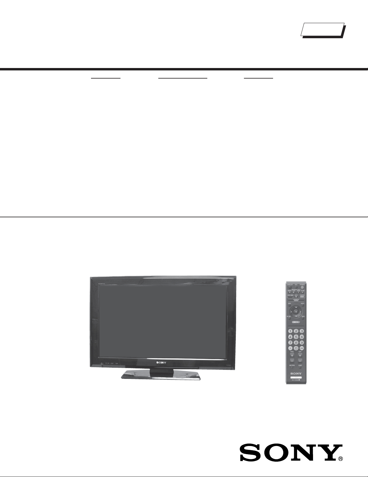
LCD DIGITAL COLOR TELEVISION

KDL-26L5000/32L5000
TABLE OF CONTENTS
SECTION TITLE PAGE SECTION TITLE PAGE
Specifi cations ................................................................................. 4
Warnings and Cautions - ENGLISH ............................................... 6
Warnings and Cautions - FRENCH ................................................ 7
Safety-Related Component Warning .............................................. 8
Safety Check-Out ......................................................................... 10
Self-Diagnostic Function ................................................................11
SECTION 1: DISASSEMBLY ............................................................... 13
1-1. Rear Cover Removal ............................................................ 13
1-2. Switch Unit Removal (Contains H1 Board) .......................... 13
1-3. A Board and G2BE (Power Supply) Board Removal ........... 14
1-4. Table-Top Stand Assembly and Under Cover Removal ....... 14
1-5. Loudspeaker Removal ......................................................... 15
1-6. Brackets and Spine Removal ............................................... 16
1-6-1. Brackets and Spine Removal
(KDL-26L5000 Only) ................................................ 16
1-6-2. Brackets and Spine Removal
(KDL-32L5000 Only) ................................................ 16
1-7. H2 Board and LCD Panel Removal ..................................... 17
1-7-1. Cleaning the LCD Panel ............................................ 17
1-8. Balancer (MT Inverter) Board Removal
(KDL-26L5000 Only) ............................................................ 18
1-9. Balancer (MT Inverter) Board Removal
(KDL-32L5000 Only) ............................................................ 19
WIRE DRESSING ........................................................................ 20
SECTION 2: SERVICE ADJUSTMENTS ............................................. 21
2-1. Resetting to Factory Defaults ............................................... 21
SECTION 3: DIAGRAMS ..................................................................... 22
3-1. Circuit Boards Location ........................................................ 22
3-2. Printed Wiring Boards and
Schematic Diagrams Information ......................................... 22
3-3. Block Diagram ...................................................................... 24
3-4. Schematics and Supporting Information .............................. 25
A Board Schematic Diagram (1 of 17) .................................. 25
A Board Schematic Diagram (2 of 17) .................................. 26
A Board Schematic Diagram (3 of 17) .................................. 27
A Board Schematic Diagram (4 of 17) .................................. 28
A Board Schematic Diagram (5 of 17) .................................. 29
A Board Schematic Diagram (6 of 17) .................................. 30
A Board Schematic Diagram (7 of 17) .................................. 31
A Board Schematic Diagram (8 of 17) .................................. 32
A Board Schematic Diagram (9 of 17) .................................. 33
A Board Schematic Diagram (10 of 17) ................................ 34
A Board Schematic Diagram (11 of 17) ................................ 35
A Board Schematic Diagram (12 of 17) ................................ 36
A Board Schematic Diagram (13 of 17) ................................ 37
A Board Schematic Diagram (14 of 17) ................................ 38
A Board Schematic Diagram (15 of 17) ................................ 39
A Board Schematic Diagram (16 of 17) ................................ 40
A Board Schematic Diagram (17 of 17) ................................ 41
G2BE Board Schematic Diagram ......................................... 43
H1 Board Schematic Diagram .............................................. 45
H2 Board Schematic Diagram .............................................. 47
SECTION 4: EXPLODED VIEWS ........................................................ 49
4-1. Rear Cover Assembly and Table-Top Stand Assembly ....... 49
4-2. Chassis ................................................................................ 50
4-3. Bezel Assembly and LCD Panel .......................................... 51
4-4. Screw Legend ...................................................................... 52
KDL-26L5000/32L5000
APPENDIX A: ENCRYPTION KEY COMPONENTS ..........................A-1
3
KDL-26L5000/32L5000
KDL-26L5000/32L5000
SPECIFICATIONS
Design and specifi cations are subject to change without notice.
VIDEO (IN) 1/2:
S Video (4-Pin Mini DIN) (Video 2 only)
Y: 1.0 Vp-p, 75 ohms unbalanced, sync negative
C: 0.286 Vp-p (Burst signal), 75 ohms
Video
1 Vp-p, 75 ohms unbalanced, sync negative
Audio
500 mVrms (Typical)
Impedance:47 kilohms
YP
(Component Video)
Y:1.0 Vp-p, 75 ohms unbalanced, sync negative
P
Signal format: 480i, 480p, 720p, 1080i, 1080p
Audio
500 mVrms (Typical)
Impedance: 47 kilohms
Video: 480i, 480p, 720p, 1080i, 1080p, 1080/24p
Audio: Two channel linear PCM 32, 44.1, and 48 kz,
16, 20 and 24 bits, Dolby Digital
Audio (HDMI IN 1 only):
500 mVrms (Typical)
Impedance: 47 kilohms
AUDIO OUT
500 mVrms (Typical)
PCM/Dolby Digital optical signal
Analog RGB (D-sub 15-pin):
0.7 Vp-p, 75 ohms, positive
Stereo mini jack
500 mVrms (Typical)
Impedance: 47 kilohms

KDL-26L5000 KDL-32L5000
)
Power Consumption
in use
in standby
Speaker Output (W)
75W 135W
Less than 0.5 W
8W + 8W 10W + 10W
Speaker/Full Range(2
mm 40 X 100 mm 34 X 160 mm
5/8
1
in
x 4 in 1
Dimensions (W x H x D)
with stand
679 x 485 x 222 mm 807 x 557 x 222 mm
mm
in
26
3/4
x 19
1/8
x 8
3/4
in 31
7/8
without stand
679 x 435 x 93 mm 807 x 508 x 94 mm
mm
in
26
3/4
x 17
1/4
x 3
3/4
in 31
7/8
wall-mount hole pattern (mm) 200 x 100 200 x 200
wall-mount screw size (mm) M4 8-12 M6 8-12
Mass
with stand
kg
lbs
10.0 kg 12.7 kg
22 lbs 1 oz 28 lbs 0 oz
without stand
kg
8.7 kg 11.4 kg
lbs 19 lbs 3 oz 25 lbs 3 oz
All measurements are approximations.
3/8
1/3
x 6
x 22 x 8
x 20 x 3
in
3/4
3/4
KDL-26L5000/32L5000
in
in
Television system
NTSC American TV Standard
ATSC (8VSB terrestrial) ATSC compliant 8VSB
QAM on cable ANSI/SCTE 07 2000
Channel coverage
Analog Digital
Terrestrial 2-69 2-69
Cable 1-135 1-135
Antenna
75-ohm external terminal for RF inputs
Panel System
LCD (Liquid Crystal Display) Panel
Display Resolution (horizontal x vertical):
1,366 dots x 768 lines
Screen Size (measured diagonally)
approx. 26 inches (KDL-26L5000 only)
approx. 31.5 inches (KDL-32L5000 only)
Supplied Accessories
Remote Commander RM-YD028
Two Size AA (R6) Batteries
Operating Instructions
Quick Setup Guide
Warranty Card
Safety and Regulatory Booklet
Attaching to the Table-Top Stand
Screws (4)
Optional Accessories
Connecting Cables
Support Belt Kit
Wall-Mount Bracket
SU-WL100 (KDL-26L5000 only)
SU-WL500 (KDL-32L5000 only)
KDL-26L5000/32L5000
5
KDL-26L5000/32L5000
WARNINGS AND CAUTIONS - ENGLISH
CAUTION
These servicing instructions are for use by qualifi ed service personnel only. To reduce the risk of electric shock, do not perform any servicing other
than that contained in the operating instructions unless you are qualifi ed to do so.
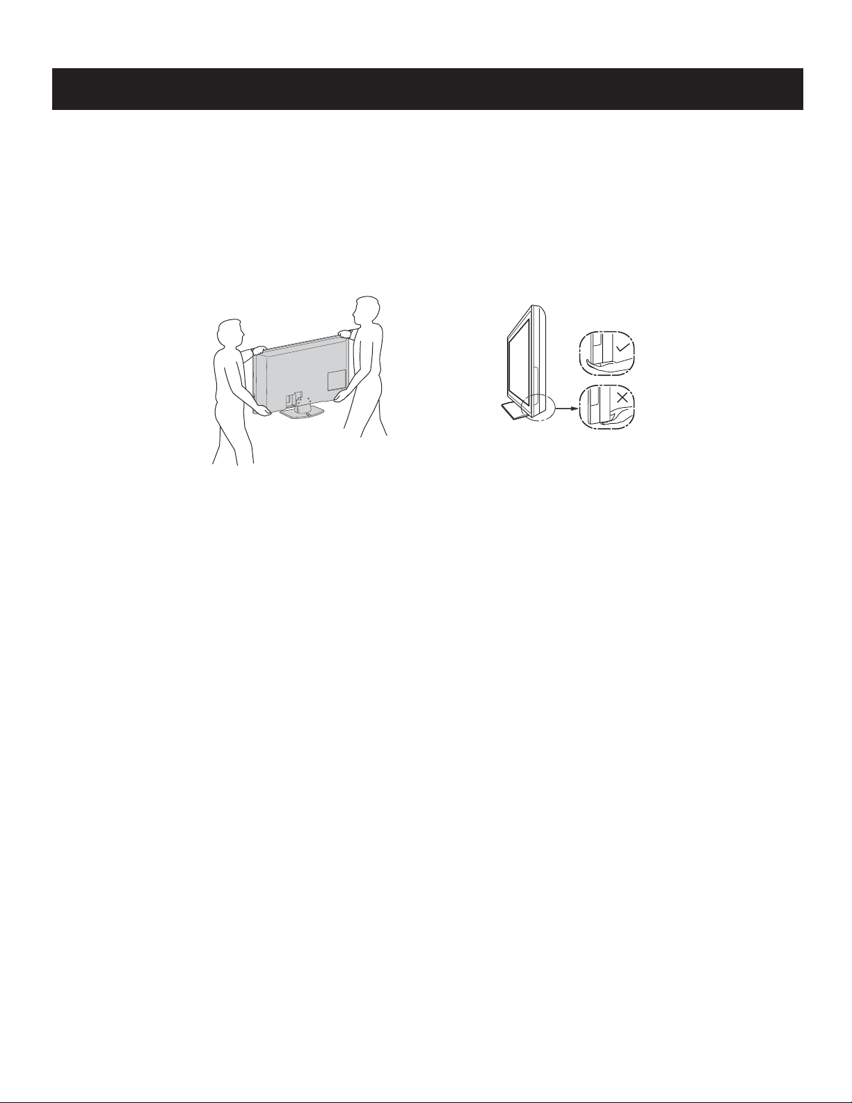
CARRYING THE TV
• Disconnect all cables when carrying the TV.
• Carry the TV with the adequate number of people; larger size TVs require two or more people.
• Placement of the hands carrying the TV is very important for safety and to avoid damage.
WARNING!!
An isolation transformer should be used during any service to avoid possible shock hazard, because of live chassis. The chassis of this receiver is
directly connected to the ac power line.
! SAFETY-RELATED COMPONENT WARNING!!
Components identifi ed by shading and ! mark on the schematic diagrams, exploded views, and in the parts list are critical for safe operation. Replace
these components with Sony parts whose part numbers appear as shown in this manual or in supplements published by Sony. Circuit adjustments that
are critical for safe operation are identifi ed in this manual. Follow these procedures whenever critical components are replaced or improper operation is
suspected.
KDL-26L5000/32L5000
6

KDL-26L5000/32L5000
WARNINGS AND CAUTIONS - FRENCH
ATTENTION!!
Ces instructions de service sont à l’usage du personnel de service qualifi é seulement. Pour prévenir le risque de choc électrique, ne pas faire
l’entretien autre que celui contenu dans le Mode d’emploi à moins que vous soyez qualifi é faire ainsi.
TRANSPORTER LE TÉLÉVISEUR
• Débranchez tous les câbles avant de transporter le téléviseur.
• Transportez le téléviseur avec le nombre de personnes approprié ; un téléviseur de grande
taille doit être transporté par au moins deux personnes.
• Lors du transport du téléviseur, l’emplacement des mains est très important pour votre
sécurité, ainsi que pour éviter de causer des dommages.
Afi n d’eviter tout risque d’electrocution provenant d’un chássis sous tension, un transformateur d’isolement doit etre utilisé lors de tout dépannage. Le
chássis de ce récepteur est directement raccordé à l’alimentation du secteur.
! ATTENTION AUX COMPOSANTS RELATIFS A LA SECURITE!!
Les composants identifi es par une trame et par une marque ! sur les schemas de principe, les vues explosees et les listes de pieces sont d’une
importance critique pour la securite du fonctionnement. Ne les remplacer que par des composants Sony dont le numero de piece est indique dans le
present manuel ou dans des supplements publies par Sony. Les reglages de circuit dont l’importance est critique pour la securite du fonctionnement
sont identifi es dans le present manuel. Suivre ces procedures lors de chaque remplacement de composants critiques, ou lorsqu’un mauvais
fonctionnement suspecte.
KDL-26L5000/32L5000
7
SAFETY-RELATED COMPONENT WARNING
KDL-26L5000/32L5000
There are critical components used in LCD color TVs that are important for safety. These components are identifi ed with shading and
mark on the schematic diagrams and the electrical parts list. It is essential that these critical parts be replaced only with the part number
specifi ed in the electrical parts list to prevent electric shock, fi re, or other hazard.
NOTE: Do not modify the original design without obtaining written permission from the manufacturer or you will void the original parts and
labor guarantee.
!
USE CAUTION WHEN HANDLING THE LCD PANEL
When repairing the LCD panel, be sure you are grounded by using a wrist band.
When installing the LCD panel on a wall, the LCD panel must be secured using the 4 mounting holes on the rear cover.
To avoid damaging the LCD panel:
do not press on the panel or frame edge to avoid the risk of electric shock.
do not scratch or press on the panel with any sharp objects.
do not leave the module in high temperatures or in areas of high humidity for an extended period of time.
do not expose the LCD panel to direct sunlight.
avoid contact with water. It may cause a short circuit within the module.
disconnect the AC adapter when replacing the backlight (CCFL) or inverter circuit.
(High voltage occurs at the inverter circuit at 650Vrms.)
always clean the LCD panel with a soft cloth material.
use care when handling the wires or connectors of the inverter circuit. Damaging the wires may cause a short.
protect the panel from ESD to avoid damaging the electronic circuit (C-MOS).
LEAKAGE CURRENT HOT CHECK CIRCUIT
KDL-26L5000/32L5000
8
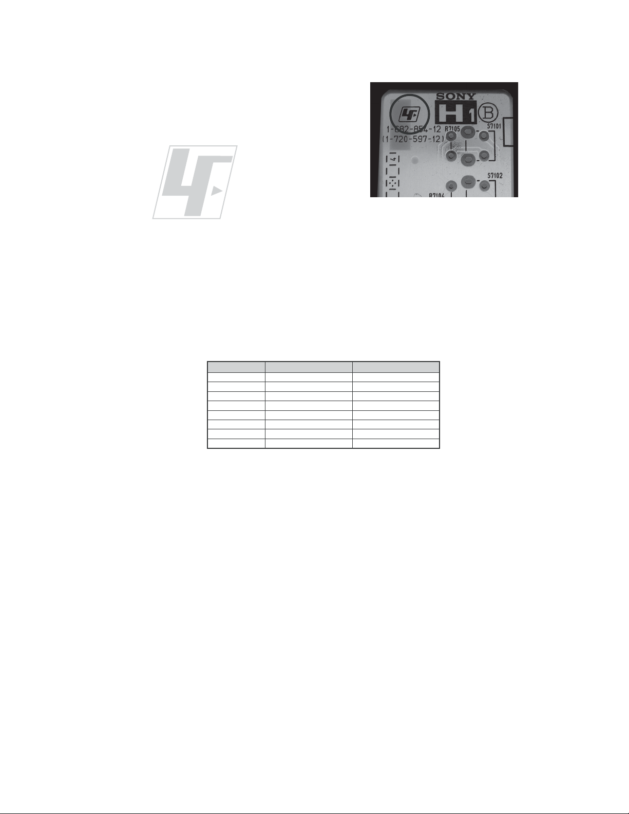
The circuit boards used in these models have been processed using
Lead Free Solder. The boards are identified by the LF logo located
close to the board designation e.g. H1 etc [ see example ]. The
servicing of these boards requires special precautions to be taken as
outlined below.
KDL-26L5000/32L5000
example 1
It is strongly recommended to use Lead Free Solder material in order to guarantee optimal quality of new solder joints.
Lead Free Solder is available under the following part numbers :
rebmuntraP retemaiD skrameR
91-500-046-7mm3.0gK52.0
02-500-046-7mm4.0gK05.0
12-500-046-7mm5.0gK05.0
22-500-046-7mm6.0gK52.0
32-500-046-7mm8.0gK00.1
42-500-046-7mm0.1gK00.1
52-500-046-7mm2.1gK00.1
62-500-046-7mm6.1gK00.1
Due to the higher melting point of Lead Free Solder the soldering iron tip temperature needs to be set to 370 degrees centigrade.
This requires soldering equipment capable of accurate temperature control coupled with a good heat recovery characteristics.
For more information on the use of Lead Free Solder, please refer to
http://www.sony-training.com
KDL-26L5000/32L5000
9
SAFETY CHECK-OUT
KDL-26L5000/32L5000
After correcting the original service problem, perform the following
safety checks before releasing the set to the customer:
1. Check the area of your repair for unsoldered or poorly soldered
connections. Check the entire board surface for solder splashes and
bridges.
2. Check the interboard wiring to ensure that no wires are “pinched” or
touching high-wattage resistors.
3. Check that all control knobs, shields, covers, ground straps, and
mounting hardware have been replaced. Be absolutely certain that
you have replaced all the insulators.
4. Look for unauthorized replacement parts, particularly transistors,
that were installed during a previous repair. Point them out to the
customer and recommend their replacement.
5. Look for parts which, though functioning, show obvious signs of
deterioration. Point them out to the customer and recommend their
replacement.
6. Check the line cords for cracks and abrasion. Recommend the
replacement of any such line cord to the customer.
7. Check the antenna terminals, metal trim, “metallized” knobs, screws,
and all other exposed metal parts for AC leakage. Check leakage as
described below.
The AC leakage from any exposed metal part to earth ground and
from all exposed metal parts to any exposed metal part having a
return to chassis, must not exceed 0.5 mA (500 microamperes).
Leakage current can be measured by any one of three methods.
1. A commercial leakage tester, such as the Simpson 229 or RCA
WT-540A. Follow the manufacturers’ instructions to use these
instructions.
2. A battery-operated AC milliampmeter. The Data Precision 245
digital multimeter is suitable for this job.
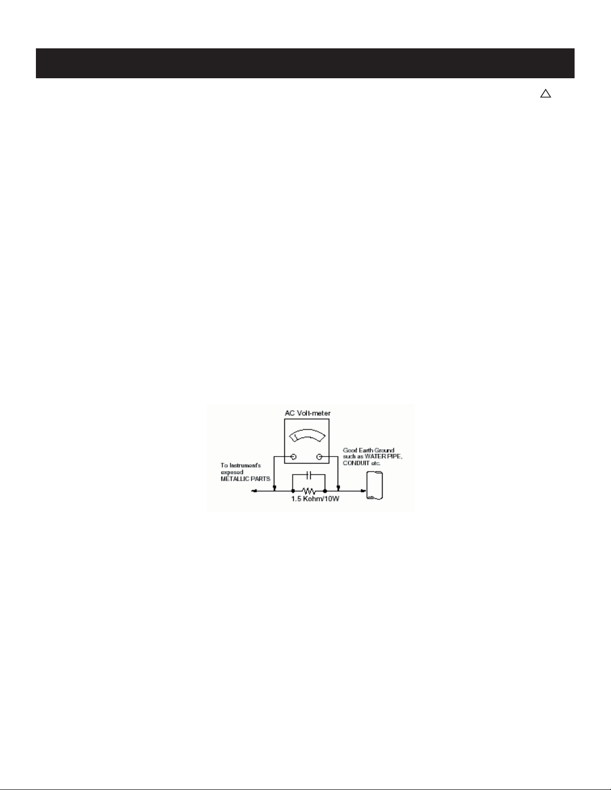
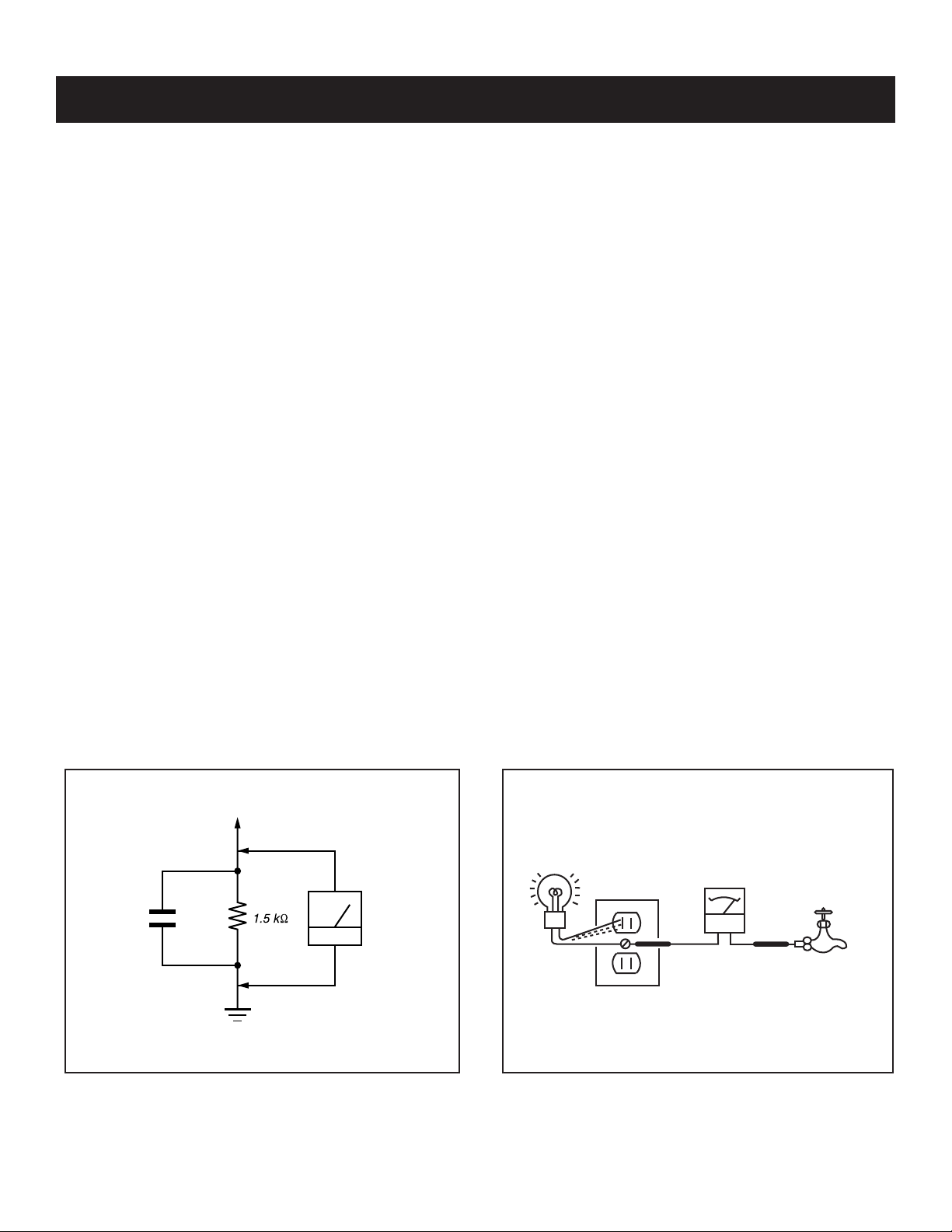
3. Measuring the voltage drop across a resistor by means of a VOM
or battery-operated AC voltmeter. The “limit” indication is 0.75
V, so analog meters must have an accurate low voltage scale.
The Simpson’s 250 and Sanwa SH-63TRD are examples of
passive VOMs that are suitable. Nearly all battery-operated digital
multimeters that have a 2 VAC range are suitable (see Figure A).
How to Find a Good Earth Ground
A cold-water pipe is a guaranteed earth ground; the cover-plate
retaining screw on most AC outlet boxes is also at earth ground. If the
retaining screw is to be used as your earth ground, verify that it is at
ground by measuring the resistance between it and a cold-water pipe
with an ohmmeter. The reading should be zero ohms.
If a cold-water pipe is not accessible, connect a 60- to 100-watt
trouble- light (not a neon lamp) between the hot side of the receptacle
and the retaining screw. Try both slots, if necessary, to locate the hot
side on the line; the lamp should light at normal brilliance if the screw
is at ground potential (see Figure B).
Leakage Test
0.15 μF
Figure A. Using an AC voltmeter to check AC leakage. Figure B. Checking for earth ground.
To Exposed Metal
Parts on Set
Earth Ground
AC
Voltmeter
(0.75V)
Trouble Light
AC Outlet Box
Ohmmeter
Cold-water Pipe
KDL-26L5000/32L5000
10
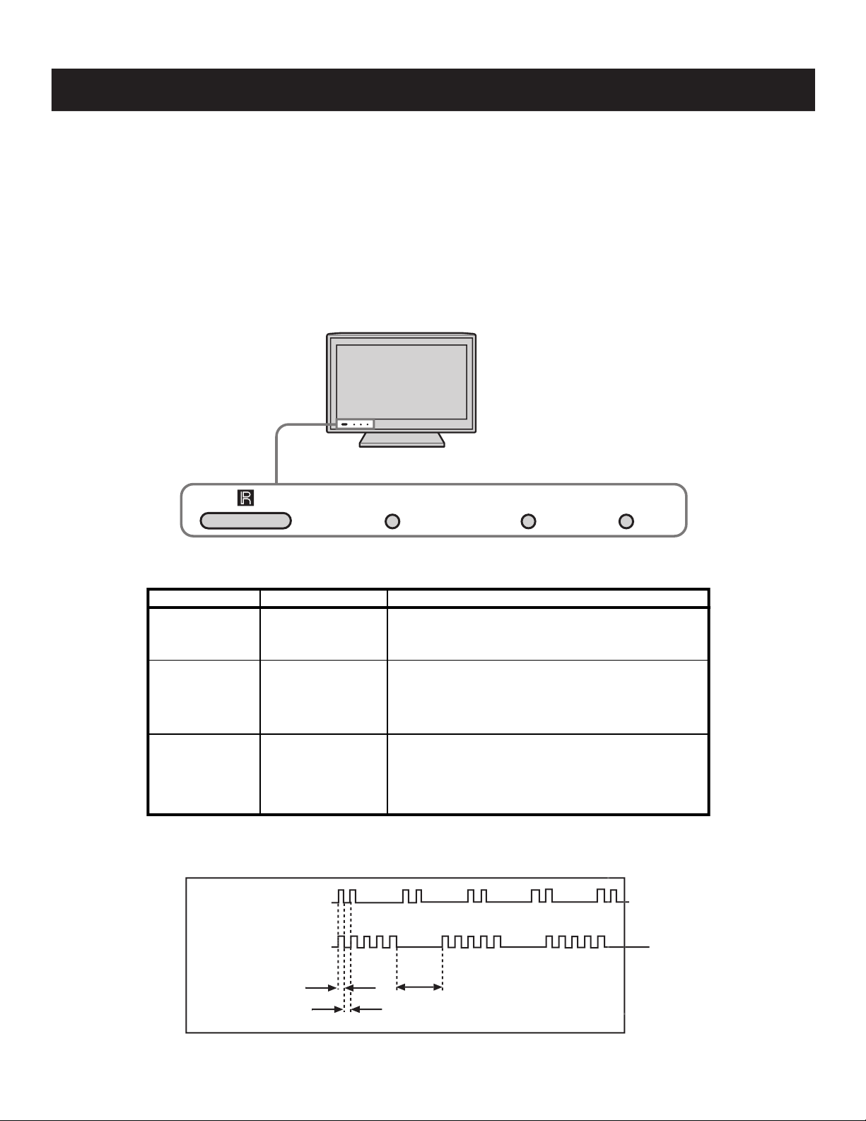
SELF-DIAGNOSTIC FUNCTION
When an error occurs, the STANDBY LED indicator will fl ash a set number of times to indicate the possible cause of the problem. If there is more than
LED LED Type Description
* Lights up in green wh
en the TV set is turned on.
* If LED blinks continuously, this may indicate
that the TV needs servicing.
STANDBY LED
P
IC OF
F/
TIMER
LED
* Lights up in red when TV is in PC standby mode.
* Lights up in green when Picture Off is activated.
*
Lights up in orange when the timer is set.
When timer is set, this LED remains lit even
when the TV is turned off.
POWER LED
Green or Orange
LED
Gre
en LED
Red LE
D
☛
KDL-26L5000/32L5000
Diagnostic Item
Description
Number of times
STANDBY lamp
flashes
Possible Location
Low B error
3 times
A (Main) Board
T-CON power error
5 times LCD Panel
Backlight error 6 times
LCD Panel
G (Power) Board
Audio abnormal detection 8 times
A
(Main) Board
Speaker
SELF CHECK
003 LOW B ERROR 1 000
1
indicates an error was detected
005 T-CON POWER ERROR 000
0
indicates no error was detected
006 BACKLIGHT ERROR 000
008 AUDIO ABNORMAL DETECTOR 000
00000 00012 00000 [Menu]Exit
00000: Panel Operation Time by Hour (max 99999)
Deletion of Penal Operation Time by <7> - > <0> ke
y
00012: Boot Count (max 99999)
00000: Total Operation Time by Hour (max 99999)
BACK
☛
☛
LED Indicators
Viewing the Self Check Diagnostic List
1. TV must be in standby mode. (Power off).
2. Press the following buttons on the Remote Commander within a second of each other:
DISPLAY
The Self Check list displays.
Results for all of the following diagnostic items are displayed on screen. No error has occurred if the screen displays a “0”.
NOTE: If the Service Menu display text is not completely visible, press the Menu
Channel 5
Volume -
TV POWER
This differs from accessing Service Adjustments.
.
button on the Remote Commander to refresh the display.
HOME
3. To exit Self Check display, turn the power off. Press [Menu] Exit.
Clearing the Self Check Diagnostic List
1. In Service Mode, press the Channel
Channel 0.
8
KDL-26L5000/32L5000
12

SECTION 1: DISASSEMBLY
KDL-26L5000/32L5000
1-1. REAR COVER REMOVAL
1
Remove 12 screws from Rear Cover
Remove 1 screw from Side Jack position
2
Remove 2 screws from Terminal position
3
Remove 2 screws from Rear Cover
4
Push side of Power Button to release tab
5
☛
while removing Rear Cover
☛
5
Bezel
Rear Cover
1
2
3
4
1-2. SWITCH UNIT REMOVAL (CONTAINS H1 BOARD)
Slide out Switch unit from Bezel
1
Disconnect 1 connector from Switch Unit (Contains H1 Board)
2
Push side of Power Switch and release Bezel tab while lifting up Switch Unit
3
☛
from Bezel
☛
Bezel
1
2
KDL-26L5000/32L5000
Switch Unit
13

1-3. A BOARD AND G2BE (POWER SUPPLY) BOARD REMOVAL
Lift top and bottom latches from Side Jack Bracket to unhook from Main Bracket
1
Disconnect 7 connectors from A Board
2
Remove 9 screws from A Board
3
Disconnect 3 connectors from G2BE Board (Power Supply)
4
Remove 6 screws from G2BE Board (Power Supply)
5
Main Bracket
Latches
2
Side Jack Cover
1
A Boar d
Main Shield
4
KDL-26L5000/32L5000
3
G2BE Board (Power Supply)
5
1-4. TABLE-TOP STAND ASSEMBLY AND UNDER COVER REMOVAL
Gently place the TV set face down onto soft cloth
1
Remove 1 screw from Under Cover
2
Remove 4 screws Table-Top Stand Assembly
3
Slide Table-Top Stand Assembly out away from Bottom Bracket
4
2
Under Cover
Bottom Bracket
1
3
Ta bl e -To p
Stand Assembly
4
KDL-26L5000/32L5000
14
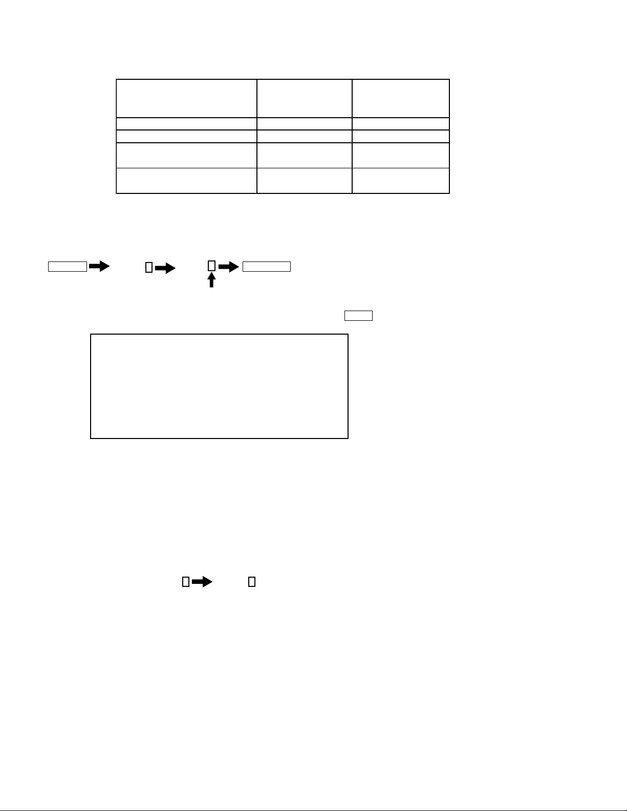
1-5. LOUDSPEAKER REMOVAL
)
Remove 1 screw from each Speaker Baffl e Plate (2 total)
1
Remove 4 screws from each loudspeaker (8 total)
2
Disconnect speaker wire
3
KDL-26L5000/32L5000
Speaker Baffle Plate (L)
1
2
Loudspeakers
Speaker Baffle Plate (R
3
3
KDL-26L5000/32L5000
15
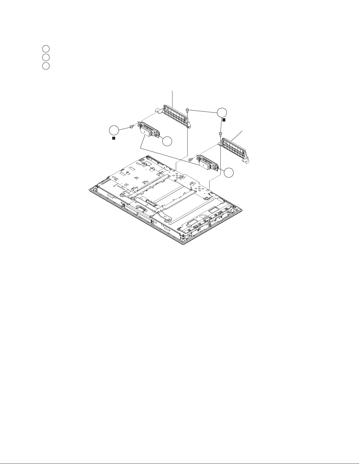
1-6. BRACKETS AND SPINE REMOVAL
1-6-1. BRACKETS AND SPINE REMOVAL (KDL-26L5000 ONLY)
Remove 1 screw from Main Bracket and Bezel
1
Remove 2 screws from Main Bracket and LCD Panel
2
Remove 2 screws from Spine
3
Remove 1 screw from Bottom Bracket
4
1
KDL-26L5000/32L5000
Main Bracket
3
Spine
2
4
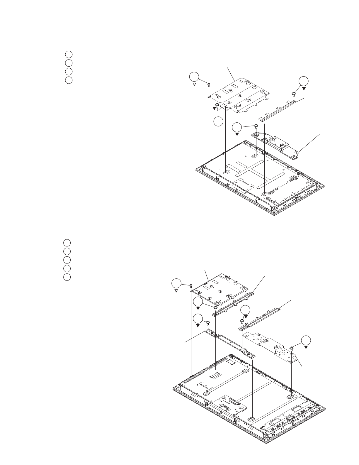
1-6-2. BRACKETS AND SPINE REMOVAL (KDL-32L5000 ONLY)
Remove 1 screw from Main Bracket and Bezel
1
Remove 2 screws from Spine (L) and Top Bracket
2
Remove 2 screws from Top Bracket
3
Remove 2 screws from Spine (R)
4
Remove 2 screws from Bottom Bracket
5
Main Bracket
1
Bottom Bracket
Spine (L)
KDL-26L5000/32L5000
Top Bracket
2
4
3
Spine (R)
5
Bottom Bracket
16
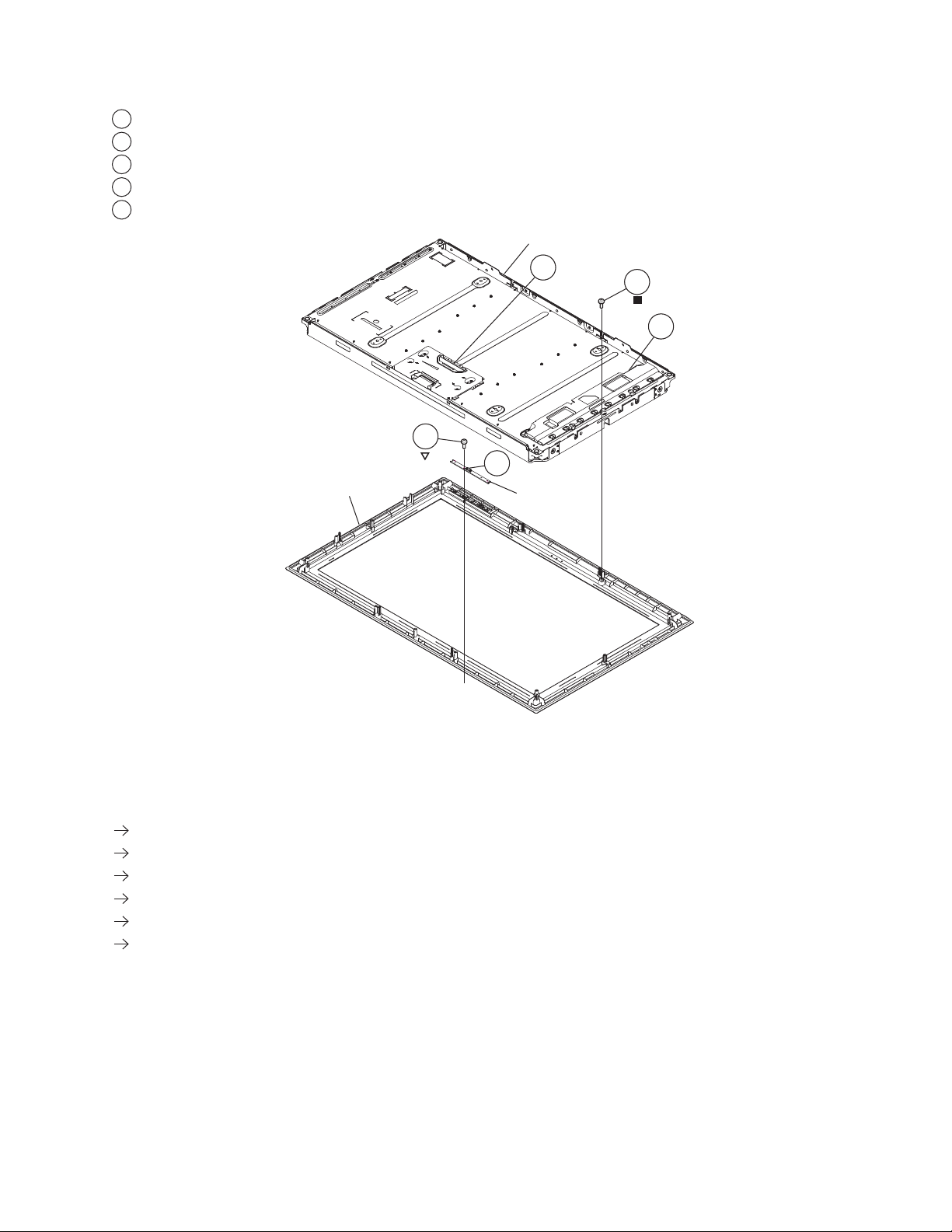
1-7. H2 BOARD AND LCD PANEL REMOVAL
Disconnect LVDS connector from T-con
1
Remove 2 screws from bottom of panel and release LCD panel from Bezel
2
Disconnect 1 connector from Inverter Board
3
Disconnect 1 connector from H2 Board
4
Remove 1 screw from H2 Board
5
KDL-26L5000/32L5000
LCD Panel
Bezel
1
2
3
5
4
H2 Board
1-7-1. CLEANING THE LCD PANEL
CAUTION: When cleaning the TV, be sure to unplug the power cord to avoid any chance of electric shock.
Clean the cabinet of the TV with a dry soft cloth.
Wipe the LCD screen gently with a soft cloth.
Stubborn stains may be removed with a cloth slightly moistened with a solution of mild soap and warm water.
If using a chemically pretreated cloth, please follow the instruction provided on the package.
Never use strong solvents such as a thinner, alcohol or benzine for cleaning.
Periodic vacuuming of the ventilation openings is recommended to ensure to proper ventilation.
KDL-26L5000/32L5000
17
 Loading...