

Sony KDL-22BX300, KDL-26BX300, KDL-32BX300, KLV-22BX300, KLV-26BX300 Service Manual
...
HISTORY
Model Name: KDL-22/26/32BX300
KDL-40BX400
SERVICE MANUAL
Click on Page Number to display details of change
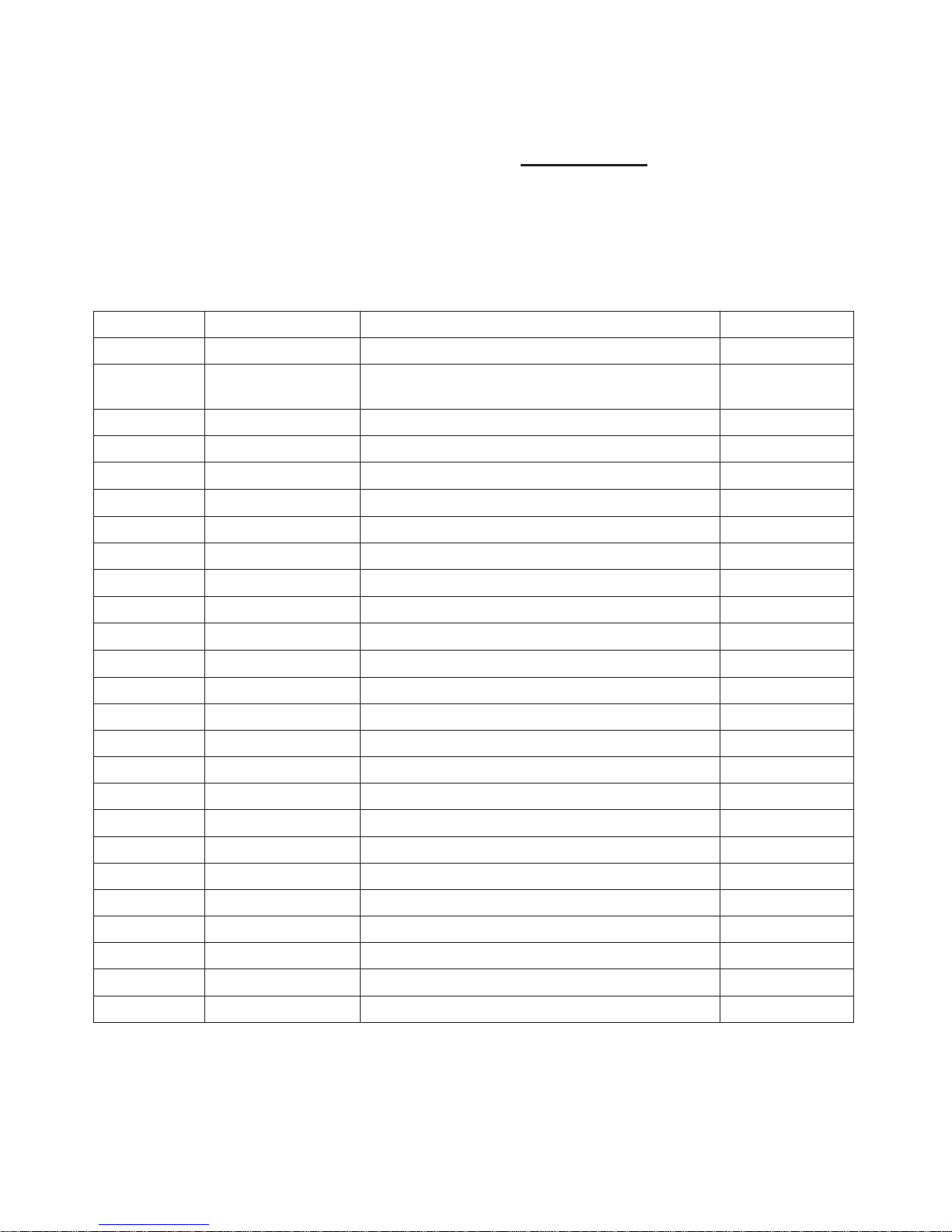
Date Part Number Description of Revisions Version
2010.02 9-883-484-01 Original Manual 1.0
2010.06 9-883-484-02
Part number changes (BAA Board)
P18, P19.
P20, P21
2.0

- 1 -
SERVICE MANUAL
AZ1-A(5-2) CHASSIS
RM-GA019
MODEL DEST MODEL DEST
KLV-22BX300 RUSS
KLV-26BX300 RUSS
KLV-32BX300 RUSS
KLV-40BX400 RUSS

– 2 –
KLV -22, 26, 32 BX300, 40 BX400
RM-GA019
TABLE OF CONTENTS
1. SAFETY NOTES
1-1. Caution Handling of LCD Panel .....................................3
1-2. Safety Check Out.............................................................3
1-3. Leakage Test ....................................................................3
1-4. WARNING ! ....................................................................3
1-5. Lead Free Information..................................................... 4
1-6. Attachment & Detachment of MDF61 Connector ......... 4
1-7. Attachment, Detachment & Confirmation of Lock
Condition of JST IBH Connector....................................4
2. SELF DIAGNOSTIC FUNCTION
2-1. Overview of Control Buttons .......................................... 5
2-2. LED Display Specification..............................................5
2-3. LED Display Control.......................................................5
2-4. LED Pattern ..................................................................... 5
2-5. Standby LED Error Display and Board
Replacement Order .......................................................... 6
2-6. Triage Chart .....................................................................7
3. TROUBLE SHOOTING
3-1. Flowchart ......................................................................... 8
3-1-1. No Power.......................................................................8
3-1-2. Video Problem............................................................... 9
3-1-3. Audio Problem .............................................................. 9
4. SERVICE ADJUSTMENTS
4-1. Accessing Self Diagnostic Menu .................................. 10
4-2. Accessing Service Mode ............................................... 10
4-3. GAISOU Adjustment .................................................... 10
Section Title P age
Section Title Pa g e
5. DIAGRAMS
5-1. Block Diagram............................................................... 11
5-1-1. KLV-22, 26, 32 BX300 .....................................11
5-1-2. KLV-40BX400 .................................................12
5-2. Wire Dressing and Connector Diagram ....................... 13
5-2-1. KLV-22BX300................................................... 13
5-2-2. KLV-26BX300................................................... 14
5-2-3. KLV-32BX300................................................... 15
5-2-4. KLV-40BX400................................................... 16
5-3. Circuit Board Location.................................................. 17
5-3-1. KLV-22BX300................................................... 17
5-3-2. KLV-26BX300................................................... 17
5-3-3. KLV-32BX300................................................... 17
5-3-4. KLV-40BX400................................................... 17
6. DISASSEMBLY, EXPLODED VIEWS AND
OTHER PARTS
6-1. Disassembly & Exploded Views ...................................18
6-1-1. KLV-22BX300 ....................................................18
6-1-2. KLV-26BX300 ....................................................19
6-1-3. KLV-32BX300 ....................................................20
6-1-4. KLV-40BX400 ....................................................21
6-2. Other Parts ..................................................................... 22
6-2-1. KLV-22BX300 ....................................................22
6-2-2. KLV-26BX300 ....................................................22
6-2-3. KLV-32BX300 ....................................................23
6-2-4. KLV-40BX400 ....................................................24
– 3 –
KLV -22, 26, 32 BX300, 40 BX400
RM-GA019
1-1. Caution Handling of LCD Panel
When installing the LCD Panel, make sure you are grounded
with a wrist band.
When installing the LCD Panel on the wall, the panel must be
secured using the 4 mounting holes on the rear cover.
1) Do not press the panel or frame edge to avoid the risk of
electric shock.
2) Do not scratch or press on the panel with any sharp
objects.
3) Do not leave the module in high temperature or in areas of
high humidity for an extended period of time.
4) Do not expose the LCD panel to direct sunlight.
5) Avoid contact with water. It may cause short circuit within
the module.
6) Disconnect the AC adapter when replacing the backlight
(CCFL) or inverter circuit. (High voltage occurs at the inverter
circuit at 650Vrms)
7) Always clean the LCD panel with a soft cloth material.
8) Use care when handling the wires or connectors of the
inverter circuit. Damaging the wires may cause a short circuit.
9) Protect the panel from ESD to avoid damaging the electronic circuit (C-MOS).
1-2. Safety Check-Out
After correcting the original service problem, perform the
following safety checks before releasing the set to the
customer:-
1) Check the area of your repair for unsoldered or poorly
soldered connections. Check the entire board surface for
solder splashes and bridges.
2) Check the interboard wiring to ensure that no wires are
"pinched" or contact high-wattage resistors.
3)Check all control knobs, shields, covers, ground straps and
mounting hardware have been replaced. Be absolutely certain
you have replaced all the insulators.
4) Look for unauthorized replacement parts, particularly
transistors that were installed during a previous repair. Point
them out to the customer and recommend their replacement.
5) Look for parts which, though functioning show obvious
signs of deterioration. Point them out to the customer and
recommend their replacement.
6) Check the line cords for cracks and abrasion.
Recommend the replacement of any such line cord to the
customer.
7) Check the antenna terminals, metal trim, "metallized"
knobs, screws and all other exposed metal parts for AC
leakage. Check leakage test as described next.
8) Live chassis can cause electric shock as its
connected to the AC power line. Therefore, use
isolation transformer and gloves when changing parts
or removing plug. Please remember high voltage is
there during servicing.
9) To follow safety after servicing, please make sure
the removed screws, parts and wires are as original
condition.
1-3. Leakage Test
The AC leakage from any exposed metal part to earth
ground and from all exposed metal parts to any exposed
metal part having a return to chassis must not exceed 0.5mA
(500 microamperes). Leakage current can be measured by
any one of the three methods:-
1. A commercial leakage tester such as the SIMPSON 229 or
RCA WT-540A. Follow the manufacturers instructions to use
those instructions.
2. A battery-operated AC milliampmeter. The DATA
PRECISION 245 digital multimeter is suitable for this job.
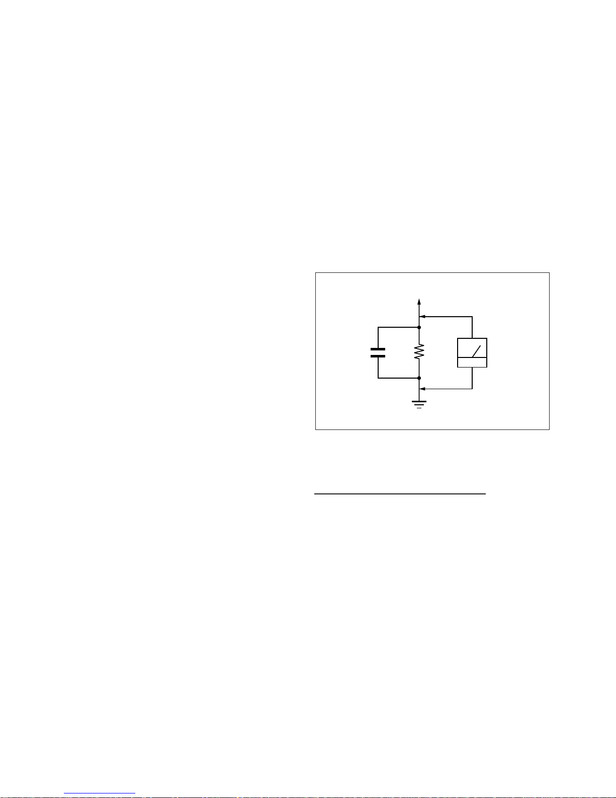
3. Measuring the voltage drop across a resistor by means of
a VOM or battery operated AC voltmeter. The 'limit' indication
is 0.75V so analog meters must have an accurate low voltage
scale. The SIMPSON'S 250 and SANWA SH-63TRD are
examples of passive VOMs that are suitable. Nearly all battery
operated digital multimeters that have a 2 VAC range are
suitable. (see Figure 1.)
1.5 k
1
0.15 μF
AC
Voltmeter
(0.75 V)
To Exposed Metal
Parts on Set
Earth Ground
SECTION 1
SAFETY NOTES
Figure 1. AC voltmeter to check AC leakage
1-4. W ARNING !
SAFETY-RELATED COMPONENT WARNING!
COMPONENTS IDENTIFIED BY SHADING AND MARK
!
ON THE EXPLODED VIEWS ARE CRITICAL FOR SAFE
OPERATION. REPLACE THESE COMPONENTS WITH
SONY PARTS WHOSE PART NUMBERS APPEAR AS
SHOWN IN THIS MANUAL OR IN SUPPLEMENTS
PUBLISHED BY SONY. CIRCUIT ADJUSTMENTS THAT ARE
CRITICAL FOR SAFE OPERATION ARE IDENTIFIED IN
THIS MANUAL. FOLLOW THESE PROCEDURES
WHENEVER CRITICAL COMPONENTS ARE REPLACED
OR IMPROPER OPERATION IS SUSPECTED.
– 4 –
KLV -22, 26, 32 BX300, 40 BX400
RM-GA019
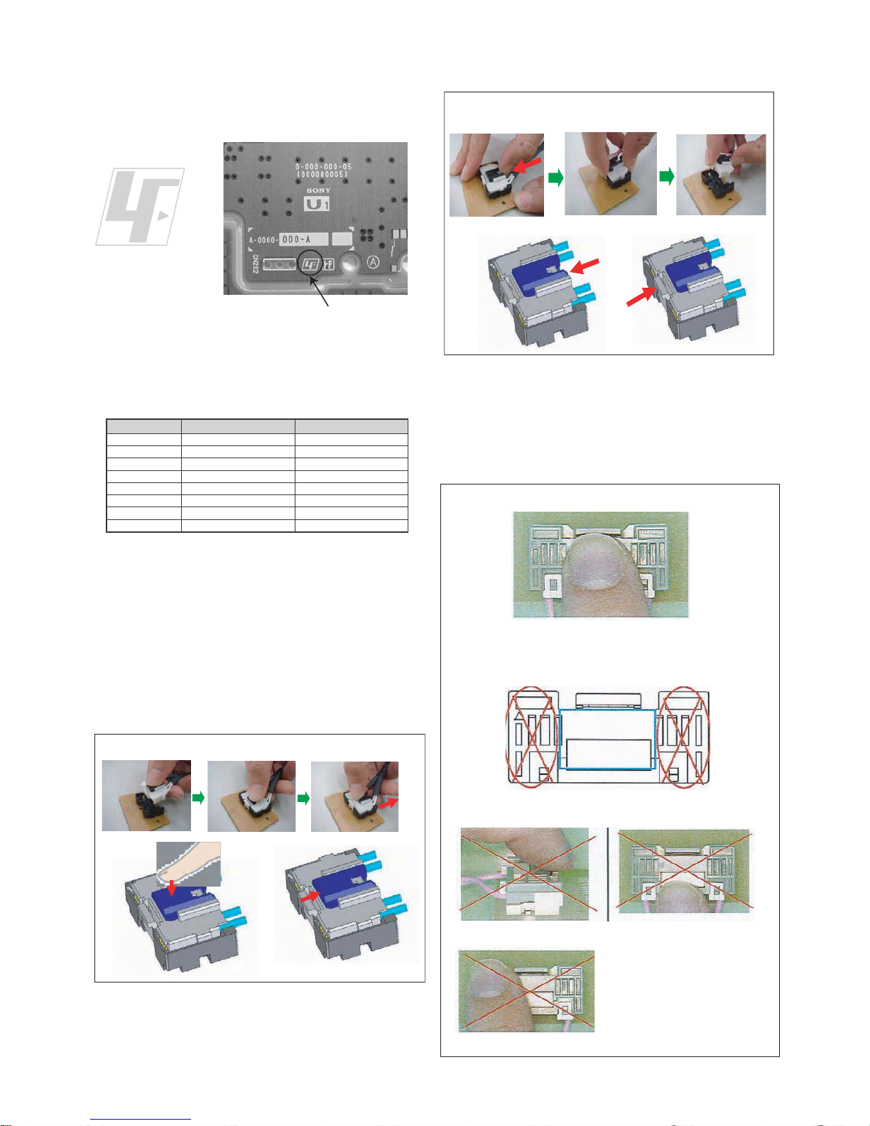
1-5. Lead Free Information
The circuit boards used in these models have been processed
using Lead Free Solder. The boards are identified by the LF
logo located close to the board designation.
The servicing of these boards requires special precautions. It
is strongly recommended to use Lead Free Solder material in
order to guarantee optimal quality of new solder joints. Lead
Free Solder is available under the following part numbers:-
Due to high melting point of Lead Free Solder, the soldering
iron tip temperature needs to be set to 370 degrees
centigrade. This requires soldering equipment capable of
accurate temperature control coupled with a good heat
recovery characteristics.
For more information on the use of Lead Free Solder,
please refer to
http://www.sony-training.com
1-6. Attachment & Detachment of MDF61 Connector
(If applicable for these models)
a) Insertion
rebmuntraP retemaiD skrameR
91-500-046-mm
m
m
m
m
m
m
m
3.0Kg52.0
02-500-046-7m4.0Kg05.0
12-500-046-7m5.0Kg05.0
22-500-046-7m6.0Kg52.0
32-500-046-7m8.0Kg00.1
42-500-046-7m0.1Kg00.1
52-500-046-7m2.1Kg00.1
62-500-046-7m6.1Kg00.1
7
Figure 2: LF logo
Figure 3: LF logo on circuit board
(1) Hold the center of a
connector.
(2) Press the center of the
connector to insert it.
(3) Slide the slider to lock the
connector.
Lock
b) Detachment
(1)
Slide the slider to release
the slider lock.
(2) Press the center lock tab
to release the lock and pull
the connector up.
Unlock
1-7. Attachment, Detachment & Confirmation of Lock
Condition of JST IBH Connector
(If applicable for these models)
Attention: This is a SAFETY CRITICAL PROCESS.
a) Attachment
(1) Press the center of the connector to insert it.
(2) Press position
(NG for red marking portion)
(3) Prohibited matter (Refer Figure A~C explanation)
Figure A
Figure B
Figure C
Figure A: Do not press lock
portion.
Figure B: Do not press the
front side of the
connector.
Figure C: Do not press the side
of the connector.
– 5 –
KLV -22, 26, 32 BX300, 40 BX400
RM-GA019
SECTION 2
SELF DIAGNOSTIC FUNCTION
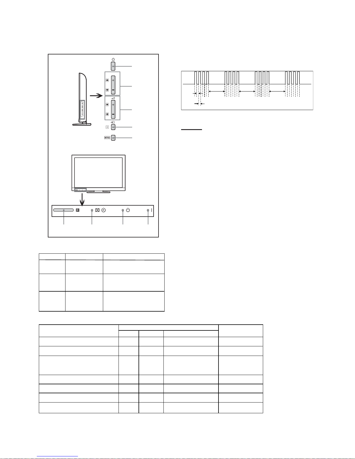
2-4. LED Pattern
When safety shutdown occurs, Standb y LED display reports the
cause by using the lightning patterns as indicated below.
Example:
The figure above shows LED display when
SHUTDOWN is caused by Balancer Error. It repeats
flashing for a specified number of times in 0.5sec/
cycle and has a 3 seconds interval of lighting off.
Please note that a 3 seconds interval of lighting off
is fixed regardless of abnormal state types.
2-1. Overview of Control Buttons
2-2. LED Display Specification
2-3. LED Display Control
PROG
Power
Program
Volume
Input Select/
Enter
Menu
Remote
Sensor
Picture
Timer
Off/Standby
Indicator
Power
Indicator
3.0 sec 3.0 sec 3.0 sec
0.5 sec
0.5 sec
LED T yp e Description
Remark
Status
LED Display
Power
Remark
POWER Green: L E D
Gr een lights at power O N.
ST ANDB
Timer/
Pic off
Y Red: One LED Red lights during standby.
Orange/Green :
Two LEDs
Gr een Lights during Picture
Off and Orange Lights during
Tim er a ctivation.
Po wer On
Green Off Off
Off
Off
Standby
Off
Off
Red
Red
Green
Off
Self Diagnosis
Orange
Red
Off
Orange
Err or of panel ID
Others (Example)
[REC][Sleep Timer][Power ON]
Red
Off
Green
[Picture O ff][On Timer][REC][Power On]
Re fer to Blinking
pattern selfdiagnosis
mode
0.5sec On / 0.5sec Off
Stand By Pic Off/Connecting/Timer
– 6 –
KLV -22, 26, 32 BX300, 40 BX400
RM-GA019
Blinking times Error Countermeasure
(Replace either/all according to sequence)
2 Main Power Error 1. GD1 (22”), POWER UNIT(G1LS) (26"), G2LE (32”),
G2HE (40”)
2. BAA board
3 DC_ALERT1/ 1. BAA board
Audio Error/ 2. GD1 (22”), POWER UNIT(G1LS) (26"),G2LE (32”),
Motionflow Error G2HE (40”)
3. TCON
4. Speaker
4 Balancer Error 1. Inverter board
2. Panel
3. GD1 (22”) , POWER UNIT(G1LS) (26"), G2LE (32”),
G2HE (40”)
4. BAA board
5 T-CON Error/ 1. T-CON
Panel ID NVM Error 2. BAA
3. LVDS Cable
4. GD1 (22”) , POWER UNIT(G1LS) (26"),G2LE (32”),
G2HE (40”)
6 Backlight Error 1. Inverter board
2. GD1 (22”) , POWER UNIT(G1LS) (26"),G2LE (32”),
G2HE (40”)
3. BAA
7 Temp Error 1. BAA
2. GD1 (22”) , POWER UNIT(G1LS) (26"), G2LE (32”),
G2HE (40”)
2-5. Standby LED Error Display and Board Replacement Order
Perform below countermeasure according Standby LED blinking times
Note1: Each of the above blinking repeats 3 seconds.
Note2: Countermeasure is list out by priority.

– 7 –
KLV -22, 26, 32 BX300, 40 BX400
RM-GA019
No Video No Video No Video No Tuner Tuner OK No HDMI No Audio
BL OK No BL BL OK Video OK Video 1-3
OSD OK No OSD Bad
BAA board
GD1 (22")
G1LS (26")
G2LE (32")
G2HE (40")
GD2 (46")
T-con board
Speaker unit
RF module
Panel module
FFC cable
Joint connector
Problem No Power BAA board Balancer TCON, Panel ID Inverter Temperature No Power BAA board BAA board BAA board BAA board BAA board BAA board BAA board
Doubtful part
few possibility
No Power
Symptom (dead set) Video distored or missing
Reference
6Blinks 7Blinks2Blinks 3Blinks 4Blinks 5Blinks
2-6. T riage Chart
 Loading...