

Sony KDL-22P5500, KDL-32P5500 Schematic

SERVICE MANUAL
SERVICE MANUAL
Ver 2.0
NEX09 CHASSIS
MODEL
MODEL
DEST
DEST
KDL-22P5500
WE / OIRT
MODEL
MODEL
DEST
DEST
KDL-32P5500
WE / OIRT
- 1 -
RM-ED017
RM-ED017
FLAT PANEL COLOR TV
FLAT PANEL COLOR TV

TABLE OF CONTENTS
Section Title Page Section Title Page
1. GENERAL ................................................................... 3
Caution................................................................ 3
Specifications ..................................................... 4
Connectors .......................................................... 5
Self Diagnosis ..................................................... 6
2. DISASSEMBLY
2-1. Rear Cover & Stand Removal (22 inches) ........ 7
2-2. Rear Cover & Stand Removal (32 inches) ........ 7
2-3. Button Bracket Removal .................................... 7
2-4. H1 Board Removal ............................................. 7
2-5. Cover, Under Removal (32 inches) ................... 8
2-6. Speaker Removal (22 inches) ............................ 8
2-7. Speaker Removal (32 inches) ............................ 8
2-8. H2 Board Removal ............................................. 8
2-9. Side Jack bracket Removal ................................ 8
2-10. A Board Removal ............................................... 9
2-11. G Board Removal (22 inches) ............................ 9
2-12. G2BE Board Removal (32 inches) .................... 9
3. ADJUSTMENTS
3-1. How to enter the Service Mode ........................ 10
3-2. Service Menu Structure ..................................... 10
3-2-1. Service General Menu ................................. 10
3-2-2. Service Alignments Menu ........................... 10
3-2-3. OSD Service Menu ...................................... 11
3-2-4. Country Selection Menu .............................. 11
3-2-5. Reset ............................................................. 11
3-3. White Balance Adjustment ............................... 12
3-3-1. Preparation ................................................... 12
3-3-2. “COOL” White Balance Adjustment .......... 12
3-3-3. “NEUTRAL” White Balance Adjustment .. 12
3-3-4. “WARM” White Balance Adjustment ........ 12
4. DIAGRAMS
4-1. Block Diagram 1 (22 inches) ............................. 13
Block Diagram 2 (32 inches) ............................. 14
4-2. Circuit Board Location ....................................... 15
4-3. Schematic Diagrams and Printed Wiring
Boards ................................................................. 15
A Board Schematic Diagram ............................. 16
G Board Schematic Diagram (22 inches) .......... 28
G2BE Board Schematic Diagram (32 inches) ... 30
H1 Board Schematic Diagram ........................... 31
H2 Board Schematic Diagram ........................... 31
A Printed Wiring Board ..................................... 32
G Printed Wiring Board (22 inches) .................. 34
G2BE Printed Wiring Board (32 inches) ........... 36
H1 Printed Wiring Board ................................... 38
H2 Printed Wiring Board ................................... 38
5. EXPLODED VIEWS
5-1a. Chassis (22 inches) ............................................. 39
5-1b. Chassis (32 inches) ............................................. 40
5-2. Bezel & Stand Assy ............................................ 41
5-3a. Rear Cover & Power Supply Cords (22 inches) 42
5-3b. Rear Cover & Power Supply Cords (32 inches) 43
Accessories & Connectors ................................. 47
Remote Commander ........................................... 47
WARNING !!
AN ISOLATION TRANSFORMER SHOULD BE USED DURING ANY
SERVICE WORK TO AVOID POSSIBLE SHOCK HAZARD DUE TO
LIVE CHASSIS, THE CHASSIS OF THIS RECEIVER IS DIRECTLY
CONNECTED TO THE POWER LINE.
SAFETY-RELATED COMPONENT WARNING !!
COMPONENTS IDENTIFIED BY SHADING AND MARKED
THE EXPLODED VIEWS AND IN THE PARTS LIST ARE CRITICAL
FOR SAFE OPERATION. REPLACE THESE COMPONENTS WITH
SONY PARTS WHOSE PART NUMBERS APPEAR AS SHOWN IN
THIS MANUAL OR IN SUPPLEMENTS PUBLISHED BY SONY.
- 2 -
ON
SECTION 1 GENERAL
How to replace the fuse.
Open the fuse compartment with
a screwdriver blade and replace
the fuse.
FUSE
SECTION 1 GENERAL
CAUTION
Lead Free Soldered Boards
example
The circuit boards used in these models have been processed using
Lead Free Solder. The boards are identified by the LF logo located
close to the board designation e.g. H1 etc [ see example ]. The
servicing of these boards requires special precautions to be taken as
outlined below.
Lead Free Solder material must be used to comply with environmental requirements of new solder joints. Lead Free Solder is available under
the following part numbers :
rebmuntraP retemaiD skrameR
91-500-046-7mm3.0gK52.0
02-500-046-7mm4.0gK05.0
12-500-046-7mm5.0gK05.0
22-500-046-7mm6.0gK52.0
32-500-046-7mm8.0gK00.1
42-500-046-7mm0.1gK00.1
52-500-046-7mm2.1gK00.1
62-500-046-7mm6.1gK00.1
Due to the higher melting point of Lead Free Solder the soldering iron tip temperature needs to be set to 370 degrees centigrade. This requires
soldering equipment capable of accurate temperature control coupled with a good heat recovery characteristics.
For more information on the use of Lead Free Solder, please refer to http://www.sony-training.com
UK PLUG WARNING
WARNING (UK Models only)
The flexible mains lead is supplied connected to a B.S. 1363 fused
plug having a fuse of the correct rating for the set. Should the fuse
need to be replaced, use a fuse of the same rating approved by ASTA
to BS 1362, ie one that carries the
IF THE PLUG SUPPLIED WITH THIS APPLIANCE IS NOT SUITABLE
FOR THE OUTLET SOCKETS IN YOUR HOME, IT SHOULD BE CUT
OFF AND AN APPROPRIATE PLUG FITTED. THE PLUG SEVERED
FROM THE MAINS LEAD MUST BE DESTROYED AS A PLUG WITH
BARED WIRES IS DANGEROUS IF ENGAGED IN A LIVE SOCKET.
ASA
T
mark.
When an alternative type of plug is used, it should be fitted with the
correct rating fuse, otherwise the circuit should be protected by the
same rating fuse at the distribution board.
LCD PANEL CAUTION
Whilst working on this product, it is not recommended to lay the TV set face down when powered up, as this can result in panel problems. If
it is necessary to power up the TV set when face down, the time should be minimised as much as possible.
- 3 -
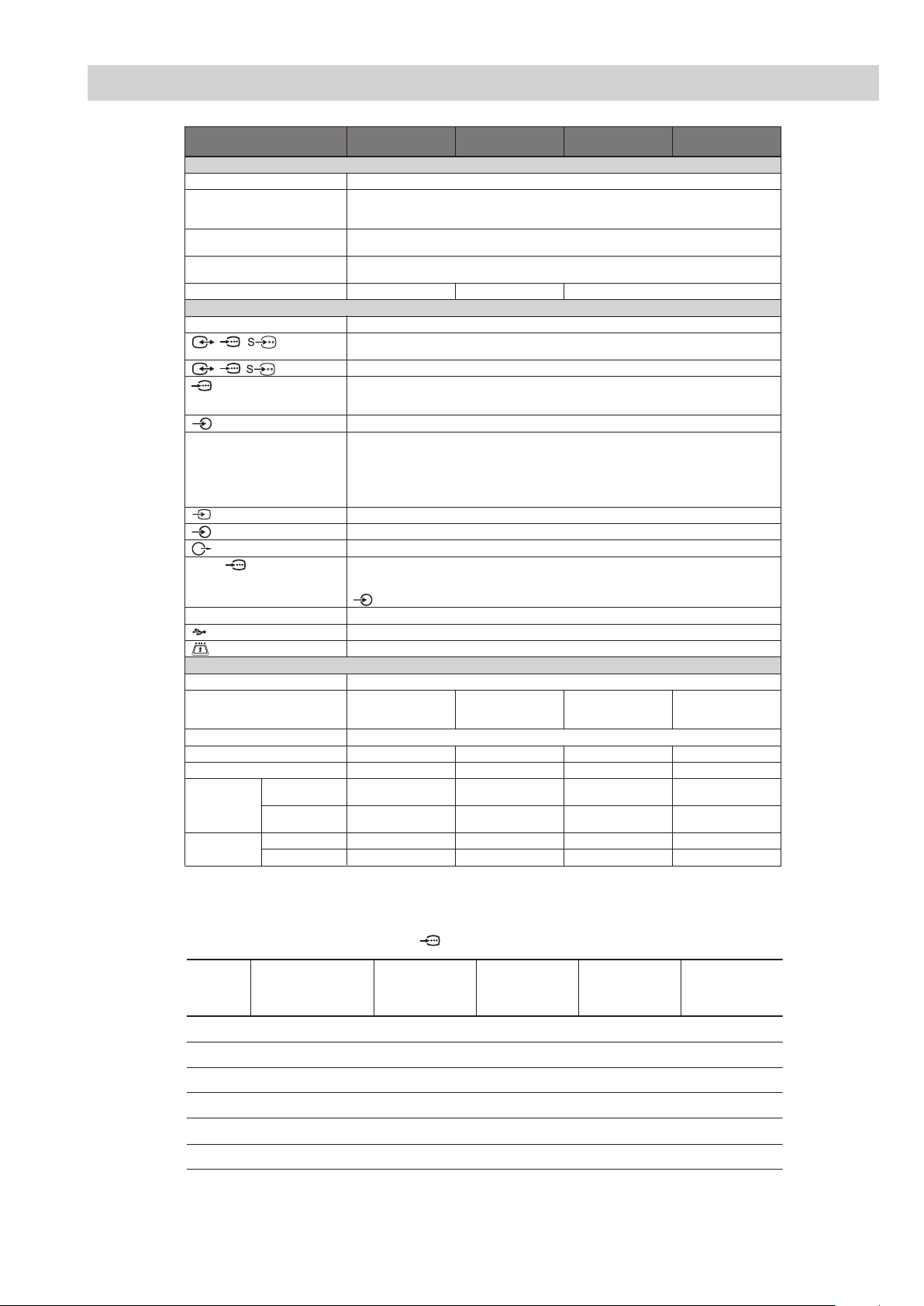
SPECIFICATIONS
Model name KDL-32S55xx/
KDL-32P55xx
KDL-26S55xx/
KDL-26P55xx
KDL-22S55xx/
KDL-22P55xx
System
Panel System
TV System
Colour/Video System
Channel Coverage
Sound Output
LCD (Liquid Crystal Display) Panel
Depending on your country/region selection
Analogue: B/G/H, D/K, L, I
Digital: DVB-T
Analogue: PAL, SECAM, NTSC 3.58, 4.43 (only Video In)
Digital: MPEG-2 MP@ML
Analogue:48.25 - 855.25 MHz
Digital: VHF Band III (177.5 - 226.5 MHz)/UHF E21 - E69 (474 - 858 MHz)
10 W + 10 W (RMS) 8 W + 8 W (RMS) 5 W + 5 W (RMS)
Input/Output jacks
Aerial
/ / AV1*
/ / AV2*
COMPONENT IN
COMPONENT IN
HDMI IN 1, 2, 3*
AV3
AV3
PC IN
i
4
75 ohm external terminal for VHF/UHF
1
21-pin scart connector including audio/video input, RGB input, S-Video input, and Analogue TV
audio/video output.
2
21-pin scart connector including audio/video input, RGB input, S-Video input, and audio/video output.
Supported formats: 1080i, 720p, 576p, 576i, 480p, 480i
Y: 1 Vp-p, 75 ohms, 0.3V negative sync/P
P
R/CR: 0.7 Vp-p, 75 ohms
Audio input (phono jacks)
Video: 1080i, 720p, 576p, 576i, 480p, 480i
Audio: Two channel linear PCM
32, 44.1 and 48 kHz, 16, 20 and 24 bits
PC (See below)
Analogue audio (minijack) (HDMI2 only) (KDL-32S55xx, KDL-32P55xx, KDL-26S55xx, KDL-26P55xx)
Analogue audio (minijack) (HDMI1 only) (KDL-22S55xx, KDL-22P55xx, KDL-19S55xx, KDL-19P55xx)
Video input (phono jack)
Audio input (phono jacks)
Audio output (Left/Right) (phono jacks)
PC Input (15 Dsub) (see page 35)
G: 0.7 Vp-p, 75 ohms, non Sync on Green/B: 0.7 Vp-p, 75 ohms/
R: 0.7 Vp-p, 75 ohms, H/V Sync: TTL level
PC audio input (minijack)
Headphones jack
USB port
CAM (Conditional Access Module) slot
B/CB: 0.7 Vp-p, 75 ohms/
Power and others
Power Requirements
Screen Size
Display Resolution
Power Consumption
Standby Power Consumption*
Dimensions
(with stand)
(w × h × d)
(without stand)
Mass (with stand)
(without stand)
*1AV1 outputs available only for analogue TV.
2
*
AV2 outputs watching screen (except PC, HDMI, Component 1080i).
3
*
Specified standby power is reached after the TV finishes necessary internal processes.
4
*
HDMI3 is available only for KDL-32S55xx, KDL-32P55xx, KDL-26S55xx and KDL-26P55xx.
220–240 V AC, 50 Hz
32 inches
(Approx. 80.0 cm
measured diagonally)
1,366 dots (horizontal) × 768 lines (vertical)
135 W 110 W 60 W 55 W
3
0.5 W or less 0.5 W or less 1 W or less 1 W or less
Approx. 80.7 × 55.7 ×
22.2 cm
Approx. 80.7 × 50.8 ×
9.4 cm
Approx. 12.7 kg Approx. 10.0 kg Approx. 6.9 kg Approx. 5.8 kg
Approx. 11.4 kg Approx. 8.7 kg Approx. 6.1 kg Approx. 5.0 kg
26 inches
(Approx. 66.1 cm
measured diagonally)
Approx. 67.9 × 48.5 ×
22.2 cm
Approx. 67.9 × 43.5 ×
9.3 cm
22 inches
(Approx. 54.8 cm
measured diagonally)
Approx. 55.8 × 41.7 ×
21.5 cm
Approx. 55.8 × 37 ×
7.9 cm
PC Input Signal Reference Chart for PC IN , HDMI IN 1, 2 and 3 *
KDL-19S55xx/
KDL-19P55xx
19 inches
(Approx. 47.0 cm
measured diagonally)
Approx. 48.7 × 37.5 ×
21.5 cm
Approx. 48.7 × 32.8 ×
7.9 cm
Signals Horizontal (Pixel) Vertical (Line)
Horizontal
frequency
(kHz)
Ver tical
frequency (Hz)
Standard
VGA 640 480 31.5 60 VGA
SVGA 800 600 37.9 60 VESA Guidelines
XGA 1024 768 48.4 60 VESA Guidelines
WXGA 1280 768 47.4 60 VESA
WXGA 1280 768 47.8 60 VESA
WXGA 1360 768 47.7 60 VESA
• This TV’s PC input does not support Sync on Green or Composite Sync.
• This TV’s PC input does not support interlaced signals.
• This TV’s PC input supports signals in the above chart with a 60 Hz vertical frequency.
* HDMI3 is available only for KDL-32S55xx, KDL-32P55xx, KDL-26S55xx and KDL-26P55xx.
- 4 -

21 Pin Connector (SCART)
1
21
19
17
15
13
11
9
7
5
3
1
20
18
16
14
12
10
CONNECTORS
Pin No 1 Signal Signal level
1 Audio output B
(right)
Audio input B
2
(right)
Audio output A
3
(left)
4 Ground (audio)
5 Ground (blue)
6 Audio input A
(left)
7 Blue input 0.7 +/- 3dB, 75 ohms positive
8 Function select
(AV control)
9 Ground (green)
10 AVlink
11 Gre en Green signal : 0.7 +/- 3d B, 75 ohms,
12 Ope n
8
6
4
2
13 Ground (red)
14 Gro und (blanking)
_ _ Red input 0.7 +/- 3dB, 75 ohms, positive
15
_ (S signal Chroma
-
input)
16 B lanking input
(Ys signal)
17 Ground (video
output)
18 Ground (video
input)
19 V ideo output 1V +/- 3dB, 75ohms, positive sync 0.3V
Video input 1V +/- 3dB, 75ohms, po sitive sync 0.3V
20
Video input
-
Y (S signal)
21 C ommon ground
(plug, shield)
Connected Not Connected (open) * at 20Hz - 20 kHz
Standard level : 0.5V rms
Output impedence : Less tha n 1kohm*
Standard level : 0.5V rms
Output impedence : More than 10kohm*
Standard level : 0.5V rms
Output impedence : Less tha n 1kohm*
Standard level : 0.5V rms
Output impedence : More than 10kohm*
High state (9.5-12V) : Par t mode
Low state (0-2V) : TV mode
Input impedence : More than 10K ohms
Input capacitance : Less than 2n F
positive
0.3 +/- 3dB, 75 ohms, positive
High state (1-3V) Low stat e (0-0.4V)
Input impedence : 75 ohms
(-3+10dB)
(-3+10dB)
1V +/- 3dB, 75ohms, positive sync 0.3V
(-3+10dB)
HDMI Connector
15 Pin D Sub Connector (PC)
Pin No Signal Assignment Pin No Signal Assignment
1 TMDS Da ta2+ 11 TMDS Cl ock Shiel d
2 TMDS Data2 Shield 12 TMDS Clock-
3TMDS Data2- 13CEC
4 TMDS Data1+ 14 Reserved (N.C. on device)
5 TMDS Data1 Shield 15 SCL
6TMDS Data1- 16SDA
7 TMDS Data0+ 17 DDC/CEC Ground
8 TMDS Data0 Shield 18 +5V Power
9 TMDS Data0- 19 Hot Plug Detect
10 TMDS Clock+
Pin No Signal Assignment Pin No Signal Assignment
1Red Out 9 +5V DC
2 Green Out 10 Sync Return (Ground)
3 Blue Out 11 Monitor ID0 in Display
4 Unused 12 DCC Serial Data
5 Ground 13 Horizontal Sync
6 Red Re turn 14 Vertical Sync
7 Green Return (Ground) 15 DCC Serial Clock
8 Blue Return (Ground)
- 5 -
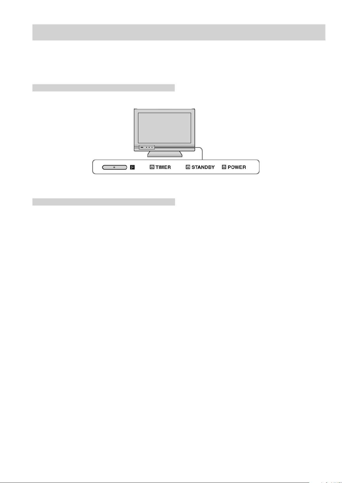
NEX SELF DIAGNOSTIC SOFTWARE
IMPORTANT:
The TV sets in this manual DO NOT contain a self-diagnostic function. If an error occurs, the TV will not stay on.
Control LED’s
LED Error Codes and Descriptions
The TV sets in this manual DO NOT contain a self-diagnostic function.
- 6 -
SECTION 2 DISASSEMBLY
2-2. Rear Cover & Stand Removal (32 inches)2-1. Rear Cover & Stand Removal (22 inches)
See Appendix-A.See Appendix-A.
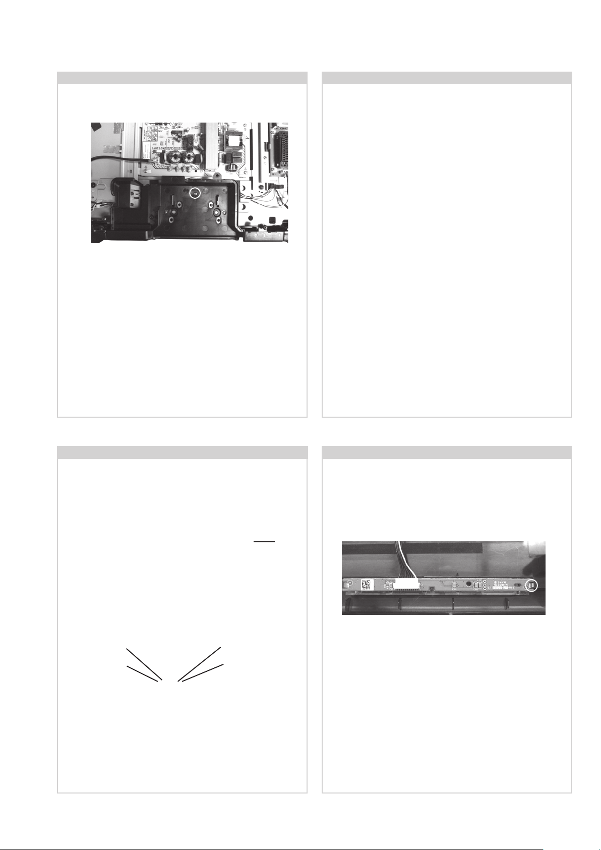
2-3. Button Bracket Removal
To remove the Button Bracket, lift the bottom of the bracket
towards the TV set. Push the top of the bracket in the
shaded area in the photograph. The bracket will then release from its boss and can be removed from the TV set.
2-4. H1 Board Removal
To remove the H1 board from the bracket, disconnect the
wire harness, remove the 2 screws circled and lift the board
out of the bracket.
Screw Part number(s) and Description(s)
7-685-504-19 SCREW, +BTP 2 X 6 2 Screws
- 7 -
2-5. Cover, Under Removal (32 inches)
To remove the Cover, Under, remove the screw circled
and ease the cover away from the TV set.
Screw Part number(s) and Description(s)
7-682-961-09 SCREW, +PSW M4X8 1 Screw
2-6. Speaker Removal (22 inches)
To remove the speakers disconnect the speaker wire harnesses from each speaker , remove the 4 screws circled from
the bracket and ease the complete assy away from the TV set.
Screw Part number(s) and Description(s)
7-685-661-79 SCREW, +BVTP2 4 X 12 4 Screws
To remove the speakers from the speaker bracket, remove
the 4 screws circled on each speaker and separate the
speakers from the bracket.
Screw Part number(s) and Description(s)
7-685-661-79 SCREW, +BVTP2 4 X 12 8 Screws
2-7. Speaker Removal (32 inches)
To remove the speakers disconnect the speaker wire
harness , remove the 1 screw circled from the bracket
and ease the complete assy away from the TV set.
Screw Part number(s) and Description(s)
2-580-640-01 SCREW, +BVTP2 4 X 16 1 Screw
Screw
To remove the speakers from the speaker bracket,
remove the 4 screws circled and separate the speaker
from the bracket.
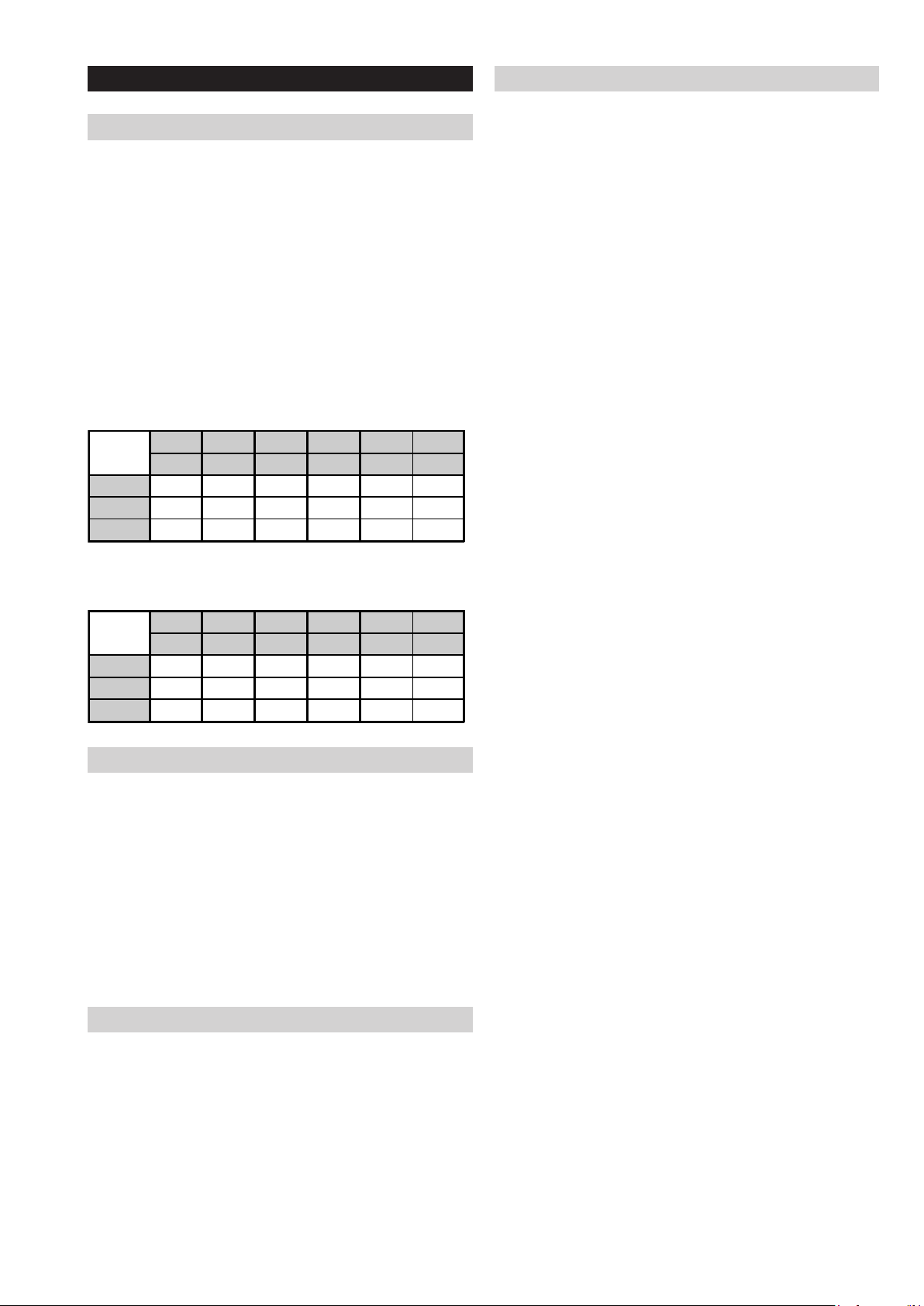
2-8. H2 Board Removal
Remove the Speakers (See Sec 2-4 2-5).
Screw
Disconnect the wire harness, release the clip circled and
ease the H2 board away from the TV set.
Screw Part number(s) and Description(s)
2-580-640-01 SCREW, +BVTP2 4 X 16 4 Screws
The procedure is identical for both speakers.
- 8 -

2-9. Side Jack Bracket Removal
2-10. A Board Removal
Clip
Clip
Release the 2 clips indicated and gently pull the bracket
away from the A board in the direction of the arrow.
2-11. G Board Removal (22 inches)
Disconnect the 6 harnesses from the board. Remove the 9
screws circled. The board can then be carefully lifted from the
TV.
Screw Part number(s) and Description(s)
4-382-854-01 SCREW, +PSW M3 X 8 9 Screws
2-12. G2BE Board Removal (32 inches)
Disconnect the 3 harnesses from the board. Remove the 6
screws circled and ease the board gently away from the back
of the TV set.
Screw Part number(s) and Description(s)
4-382-854-01 SCREW, +PSW M3 X 8 6 Screws
Disconnect the 3 harnesses from the board. Remove the 6
screws circled and ease the board gently away from the back
of the TV set.
Screw Part number(s) and Description(s)
4-382-854-01 SCREW, +PSW M3 X 8 6 Screws
- 9 -

SECTION 3 ADJUSTMENTS
3-1. How to enter the Service Mode
Service adjustments to this model can be performed using the
supplied Remote Commander RM-ED017.
1. Turn on the power to the TV set.
2. Press the following sequence of buttons on the Remote
Commander.
i+
(ON SCREEN
DISPLAY)
3. The following menu appears on the screen (See Pic.1).
Pic.1
5
(DIGIT 5) (VOLUME +)
+
I/
3-2. Service Menu Structure
The following description shows the items that can be
viewed and/or adjusted using the Service Menu.
3-2-1. Service General Menu
The following menu appears on the screen when you enter
the ‘Service General Menu’ (See Pic.2). This menu allows
you to view the product information, set the TV into Aging
Mode and perform Software Upgrade to the TV set.
Pic.2
4. Move to the corresponding adjustment item using the
‘ ’ or ‘ ’ arrow buttons on the Remote Commander.
5. Press the ‘ ’ arrow button to enter into the required menu
item.
6. Adjust the data value using the ‘ ’ or ‘ ’ arrow buttons on
on the Remote Commander.
7. To go back at any time press the ‘ ’ button on the Remote
Commander.
8. Ensure you return to the top level menu, shown above in
Pic 1, and press the Green button on the Remote
Commander to Store all the adjustments.
9. Press the Red button or ‘Menu’ button on the Remote
Commander to quit the Service Mode when all adjustments
have been completed.
• After carrying out the service adjustments, to prevent the
customer accessing the ‘Service Menu’ switch the TV set
OFF and then ON again.
3-2-2. Service Alignments Menu
The following menu appears on the screen when you enter
the ‘Service Alignments Menu’ (See Pic.3). This menu
allows adjustment of the TV picture levels. These adjustments
are set during manufacture and should not normally require
further adjustment.
Pic.3
- 10 -

3-2-3. OSD Service Menu
3-2-4. Country Selection Menu
The following menu appears on the screen when you enter
the ‘OSD Service Menu’ (See Pic.4). This menu
allows viewing and adjustment of the AGC and viewing of the
Sound Status.
Pic.4
The following menu appears on the screen when you enter
the ‘Country Selection Menu’ (See Pic.5). Using this menu
the destination country of the TV can be set.
Pic.5
3-2-5. Reset
Selection of ‘Reset’ (See Pic.6) allows the TV to be reset to
factory shipping condition. This will restore all settings to those
which were contained in the TV on first shipment.
Pic.6
- 11 -
3-3. White Balance adjustment
3-3-4. “WARM ” White Balance Adjustment
3-3-1. Preparation
1. Allow approximately 30 minutes for the set to warm up
before proceeding with the white balance adjustment.
2. Connect the signal source to the 3 terminals of the
Component In input (Y/Pb/Pr).
3. Set the Picture Mode to “VIVID” in the user menu.
4. Select the Component In input.
5. Open the Factory Service Menu (see section 3-1.) and select
“Service Alignments Menu”.
6. Set “White Point Red”, “White Point Green”, “White Point
Blue” and “Black Level Offset Red”, “Black Level Offset
Green”, “Black Level Offset Blue” to average values as
shown in Table 1 (22 inches) and Table 2 (32 inches).
Table 1
22 inches
Red Green Blue Red Green Blue
Gain Gain Gain Offset Offset Offset
Cool 121.8 115.05 125 7.55 7 2.5
Neutral 120.65 114 110.25 7.55 7 2.2
Warm 123.25 104.1 81.0 9.3 7 3.45
1. Select “WARM” from Color Tone in Service Alignments
Menu.
2. Input 70IRE full white pattern signal into Component In.
3. Adjust “White Point Red”, “White Point Green”, “White Point
Blue” in Service Alignments Menu if needed.
4. Input 25IRE full white pattern signal into Component In.
5. Adjust “Black Level Offset Red”, “Black Level Offset Green”,
“Black Level Offset Blue” in Service Alignments Menu if
needed.
6. Repeat steps 2 to 5 to achieve desired White Balance.
7. Save the settings.
Table 2
32 inches
Red Green Blue Red Green Blue
Gain Gain Gain Offset Offset Offset
Cool 127 107.6 115.15 7.9 7 10.9
Neutral 127 102.75 111.75 7 7 8.3
Warm 126.85 90.8 59.7 5.55 5 10.15
3-3-2. “Cool ” White Balance Adjustment
1. Select “COOL” from Color Tone in Service Alignments
Menu.
2. Input 70IRE full white pattern signal into Component In.
3. Adjust “White Point Red”, “White Point Green”, “White Point
Blue” in Service Alignments Menu if needed.
4. Input 25IRE full white pattern signal into Component In.
5. Adjust “Black Level Offset Red”, “Black Level Offset Green”,
“Black Level Offset Blue” in Service Alignments Menu if
needed.
6. Repeat steps 2 to 5 to achieve desired White Balance.
3-3-3. “NEUTRAL ” White Balance Adjustment
1. Select “NEUTRAL” from Color Tone in Service Alignments
Menu.
2. Input 70IRE full white pattern signal into Component In.
3. Adjust “White Point Red”, “White Point Green”, “White Point
Blue” in Service Alignments Menu if needed.
4. Input 25IRE full white pattern signal into Component In.
5. Adjust “Black Level Offset Red”, “Black Level Offset Green”,
“Black Level Offset Blue” in Service Alignments Menu if
needed.
6. Repeat steps 2 to 5 to achieve desired White Balance.
- 12 -
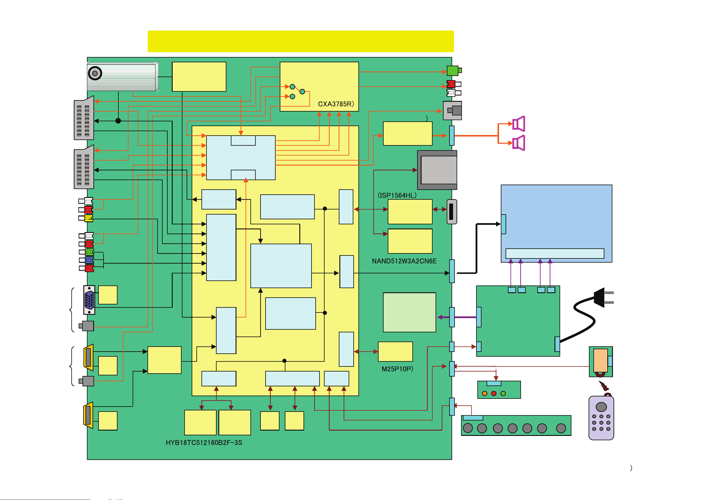
4-1. BLOCK DIAGRAM 1
RF in
TV Tuner
NAND Flash
4MB
DDR2
32MB
Main board
Micro
processor
DC-DC/
Reg. ICs
18.5“/21.6”WXGA DVB-T TV System Architecture
Line Out
LCD Panel
Power
&Inverter
Speaker
5W+5W
Remote
Controller
Analog Front End
I/O
Panasonic
ENG37E10KF
Audio
Processor
AC in
YPbPr
HDMI 1
PC
Video 1
I2S
Keyboard
VOL + CH +Enter/
Input
VOL - CH-
Power
Menu
EEP
ROM
USB 2.0
TS
HDMI
LVDS
EEP
ROM
(PNX8541)
( x2)
()
(cxb1444R)
8bit
Video 2
SIF
SPDIF
Digital
Front End
HDMI
Switch
I2S
Ir
Rx
LED
Ir
EEP
ROM
(
PCMCIA
Flash
HP Out
(TDA10048HN)
(
EEP
ROM
(M24C64)
(M24C04)
(
HDMI 2
(side)
EEP
ROM
Video 3
(side)
PCI
controller
CVBS
Power AMP
(TFA9810T
AMPs &
Selector
DDR2
32MB
PCI
SPI
MCU
Memory
Controller
I/O
Digital Video
Processor
Demodulator
18.5“ : CMO M185 B1- L01
21.6“: CMO V216B1- L01
CVBS/YC/
RGB
CVBS/YC/
RGB
Back Light
RRS1002-8902E
- 13 -
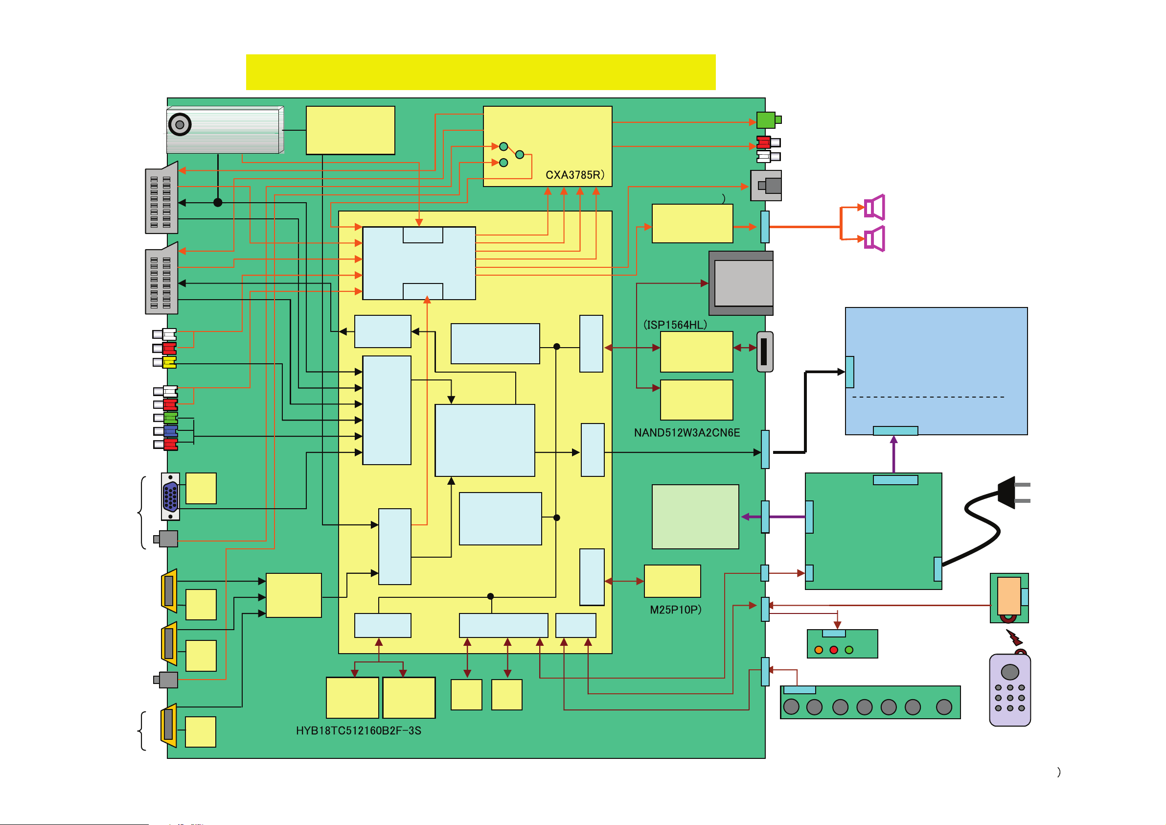
4-1. BLOCK DIAGRAM 2
RF in
TV Tuner
NAND Flash
4MB
DDR2
32MB
Main board
Micro
processor
DC-DC/
Reg. ICs
26“/32” WXGA DVB-T TV System Architecture
Line Out
LCD Panel
Power supply
unit (PSU)
(G2)
Inverter
Speaker
10W+10W (32”)
8W+8W (26”)
Remote
Controller
Analog Front End
I/O
Panasonic
ENG37E10KF
Audio
Processor
AC in
YPrPb
HDMI 1
PC
Video 1
I2S
HDMI 3
Keyboard
VOL + CH +Enter/
Input
VOL - CH-
Power
Menu
EEP
ROM
USB 2.0
TS
HDMI
LVDS
EEP
ROM
EEP
ROM
(PNX8541)
( x2)
()
(cxb1444R)
8bit
Video 2
SIF
SPDIF
Digital
Front End
HDMI
Switch
I2S
Ir
Rx
LED
Ir
EEP
ROM
(
PCMCIA
Flash
HP Out
(TDA10048HN)
(
EEP
ROM
(M24C64)
(M24C04)
(
HDMI 2
(side)
EEP
ROM
Video 3
(side)
PCI
controller
CVBS
Power AMP
(TFA9810T
AMPs &
Selector
DDR2
32MB
PCI
SPI
MCU
Memory
Controller
I/O
Digital Video
Processor
Demodulator
32“: SL C D
26“: CMO V260B1-L11
CVBS/YC/
RGB
CVBS/YC/
RGB
RRS1002-8902E
LTZ320AA03
- 14 -
4-2. CIRCUIT BOARD LOCATION
5-2. CIRCUIT BOARD LOCATION
A (MAIN)
G (POWER) 22 inches
G2BE (POWER) 32 inches
C
C
N
VM
CVM Board
H
D1
4-3. SCHEMATIC DIAGRAMS AND
5-3. SCHEMATIC DIAGRAMS AND
PRINTED WIRING BOARDS
PRINTED WIRING BOARDS
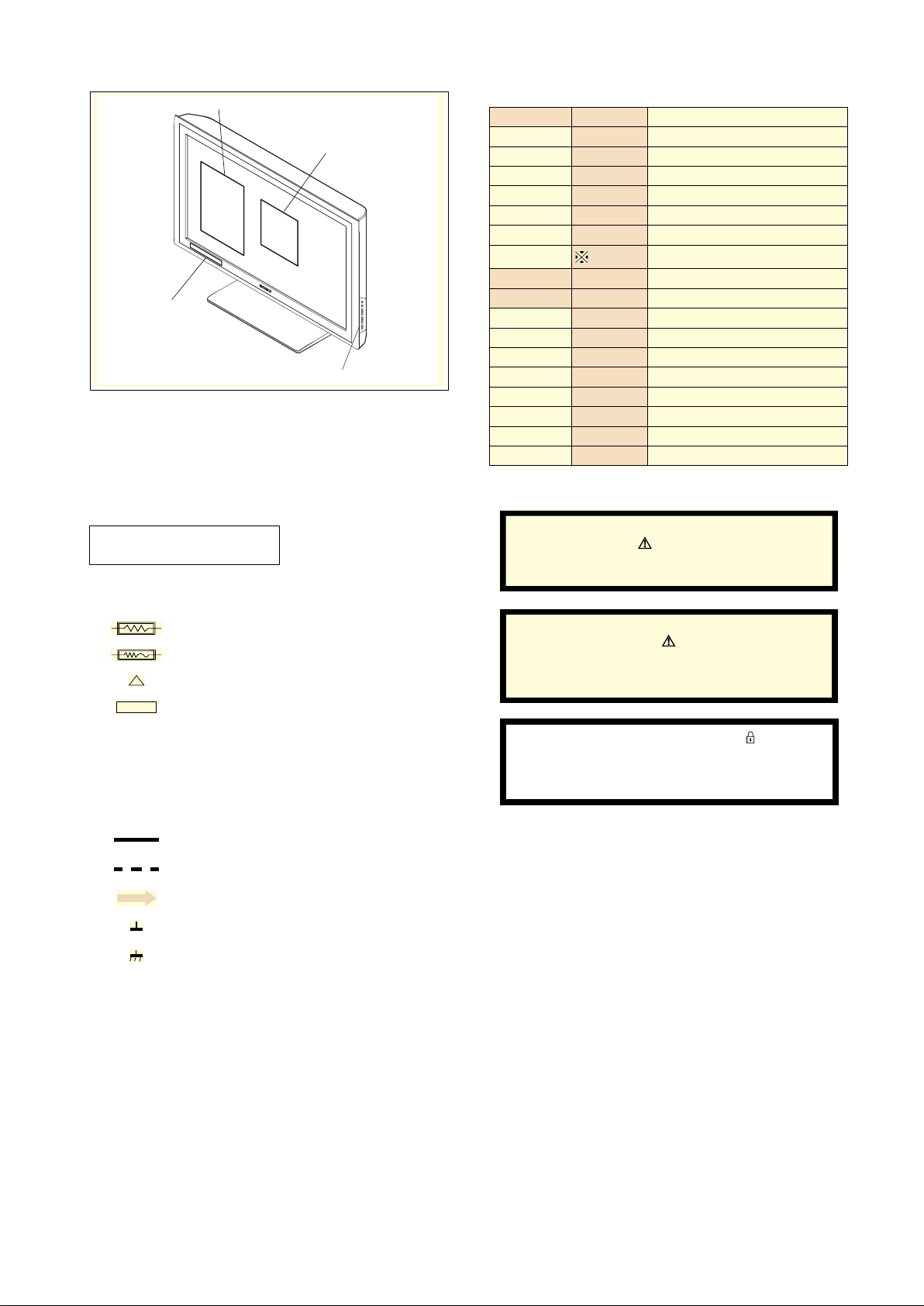
Note :
• All capacitors are in µF unless otherwise noted.
• pF : µµF 50WV or less are not indicated except for
electrolytic types.
• Indication of resistance, which does not have one for
rating electrical power, is as follows.
Pitch : 5mm
Electrical power rating : 1/4W
• Chip resistors are 1/10W
• All resistors are in ohms.
k = 1000 ohms, M = 1000,000 ohms
• : nonflammable resistor.
• : fusible resistor.
• : internal component.
• : panel designation or adjustment for repair.
• All variable and adjustable resistors have
characteristic curve B, unless otherwise noted.
• All voltages are in Volts.
• Readings are taken with a 10Mohm digital mutimeter.
• Readings are taken with a color bar input signal.
• Voltage variations may be noted due to normal production
tolerences.
•: B + bus.
A
H2 (IR & LED)
A Board
D2
D
H1 (KEY)
S1 Board
A
J
A1
A2
Reference Information
RESISTOR RN
RC
FPRD
FUSE
RS
RB
RW
COIL LF-8L
CAPACITOR TA
PS
PP
PT
MPS
MPP
ALB
ALT
ALR
Note :
The components identified by shading
and marked are critical for safety.
Replace only with the part numbers
specified in the parts list.
Note :
Les composants identifiés par une trame et
par une marque sont d'une importance
critique pour la sécurité. Ne les remplacer
que par des pièces de numéro spécifié.
specified.
Note :
The components identified by mark
confidential information.
Strictly follow the instructions whenever the
components are repaired and/or replaced.
: METAL FILM
: SOLID
: NON FLAMMABLE CARBON
: NON FLAMMABLE FUSIBLE
: NON FLAMMABLE METAL OXIDE
: NON FLAMMABLE CEMENT
: NON FLAMMABLE WIREWOUND
: ADJUSTMENT RESISTOR
: MICRO INDUCTOR
: TANTALUM
: STYROL
: POLYPROPYLENE
: MYLAR
: METALIZED POLYESTER
: METALIZED POLYPROPYLENE
: BIPOLAR
: HIGH TEMPERATURE
: HIGH RIPPLE
contain
• : B - bus.
• : RF signal path.
• : earth - ground.
• : earth - chassis.
- 15 -
 Loading...