

Page 1

HISTORY INFORMATION FOR THE FOLLOWING MANUAL:
SERVICE MANUAL
MODEL NAME REMOTE COMMANDER DESTINATION
KDL-22L4000
KDL-22L4000
KDL-22L4000
KDL-22L4000
RM-YD025 US
RM-YD025 CANADA
RM-YD025 MEXICO
RM-YD025 LATIN AMERICA
CZ1R
CHASSIS
ORIGINAL MANUAL ISSUE DATE: 9/2008
:UPDATED ITEM
☛
REVISION DATE SUBJECT
9/2008 No revisions or updates are applicable at this time.
10/2008 Removed Self Diagnosis logo from Front Cover and Self Diagnostic Function page.
Replaced pages 2 and 11.
LCD DIGITAL COLOR TELEVISION
9-883-801-02
Page 2
SERVICE MANUAL
MODEL NAME REMOTE COMMANDER DESTINATION
CZ1R
CHASSIS
KDL-22L4000
KDL-22L4000
KDL-22L4000
KDL-22L4000
RM-YD025 US
RM-YD025 CANADA
RM-YD025 MEXICO
RM-YD025 LATIN AMERICA
9-883-801-02
KDL-22L4000 RM-YD025
LCD DIGITAL COLOR TELEVISION
Page 3

KDL-22L4000
TABLE OF CONTENTS
SECTION TITLE PAGE SECTION TITLE PAGE
Specifi cations ................................................................................. 4
Warnings and Cautions .................................................................. 6
Safety-Related Component Warning .............................................. 8
Safety Check-Out ......................................................................... 10
Self-Diagnostic Function ................................................................11
SECTION 1: DISASSEMBLY ............................................................... 12
1-1. Rear Cover Removal ............................................................ 12
1-2. Function Key and H1 Board Removal .................................. 12
1-3. A Board and G Board Removal ............................................ 13
1-4. Table-Top Stand Assembly and Under Cover Removal ....... 13
1-5. Loudspeaker Removal ......................................................... 14
1-6. Bottom Cover, H2 Board, H3 Board, IR Lens and
LED Lens Removal .............................................................. 14
1-7. LCD Panel Removal ............................................................. 15
1-7-1. Cleaning the LCD Panel ............................................ 15
Wire Dressing ............................................................................... 16
SECTION 2: SERVICE ADJUSTMENTS ............................................. 17
2-1. Accessing Service (Factory) Mode ...................................... 17
2-2. Reviewing Service (Factory) Mode ...................................... 18
2-3. Resetting to Factory Defaults after Board Replacement ...... 18
2-4. Viewing Model Information ................................................... 19
SECTION 3: DIAGRAMS ..................................................................... 20
3-1. Circuit Boards Location ........................................................ 20
3-2. Printed Wiring Boards and
Schematic Diagrams Information ......................................... 20
3-3. Block Diagram ...................................................................... 22
3-4. Schematics and Supporting Information .............................. 23
A Board Schematic Diagram (1 of 21) .................................. 23
A Board Schematic Diagram (2 of 21) .................................. 24
A Board Schematic Diagram (3 of 21) .................................. 25
A Board Schematic Diagram (4 of 21) .................................. 26
A Board Schematic Diagram (5 of 21) .................................. 27
A Board Schematic Diagram (6 of 21) .................................. 28
A Board Schematic Diagram (7 of 21) .................................. 29
A Board Schematic Diagram (8 of 21) .................................. 30
A Board Schematic Diagram (9 of 21) .................................. 31
A Board Schematic Diagram (10 of 21) ................................ 32
A Board Schematic Diagram (11 of 21) ................................ 33
A Board Schematic Diagram (12 of 21) ................................ 34
A Board Schematic Diagram (13 of 21) ................................ 35
A Board Schematic Diagram (14 of 21) ................................ 36
A Board Schematic Diagram (15 of 21) ................................ 37
A Board Schematic Diagram (16 of 21) ................................ 38
A Board Schematic Diagram (17 of 21) ................................ 39
A Board Schematic Diagram (18 of 21) ................................ 40
A Board Schematic Diagram (19 of 21) ................................ 41
A Board Schematic Diagram (20 of 21) ................................ 42
A Board Schematic Diagram (21 of 21) ................................ 43
G Board Schematic Diagram (1 of 2) ................................... 45
G Board Schematic Diagram (2 of 2) ................................... 46
H1 Board Schematic Diagram .............................................. 48
H2 Board Schematic Diagram .............................................. 50
H3 Board Schematic Diagram .............................................. 52
KDL-22L4000
SECTION 4: EXPLODED VIEWS ........................................................ 54
4-1. Rear Cover Assembly and Table-Top Stand Assembly ....... 54
4-2. Chassis ................................................................................ 55
4-3. Screw Legend ...................................................................... 56
APPENDIX A: ENCRYPTION KEY COMPONENTS ..........................A-1
3
Page 4
SPECIFICATIONS
KDL-22L4000
Power Requirements
Power Consumption
In Use (Max)
In Standby
110V - 240 V AC, 50/60Hz
55W
Less than 1.0 W
VIDEO (IN) 1/2:
S VIDEO (4-Pin Mini DIN) (VIDEO 2 only):
Y: 1.0 Vp-p, 75 ohms unbalanced, sync negative
C: 0.286 Vp-p (Burst signal), 75 ohms
VIDEO:
1.0 Vp-p, 75 ohms unbalanced, sync negative
AUDIO:
500 mVrms (100% modulation)
Impedance: 47 kilohms
COMPONENT IN:
YP
(Component Video):
BPR
Y: 1.0 Vp-p, 75 ohms unbalanced, sync negative
PB: 0.7 Vp-p, 75 ohms
PR: 0.7 Vp-p, 75 ohms
Signal format: 480i, 480p, 720p, 1080i
AUDIO:
500 mVrms (100% modulation)
Impedance: 47 kilohms
HDMI IN:
HDMI: Video: 480i, 480p, 720p, 1080i, 1080p
Audio: Two channel linear PCM 32, 44.1
and 48 kHz, 16, 20 and 24 bits
AUDIO: 500 mVrms (100% modulation)
Impedance: 47 kilohms
AUDIO OUT:
500 mVrms (100% modulation)
DIGITAL AUDIO OUT (OPTICAL):
Optical Digital Audio Output (PCM/Dolby Digital)
PC IN:
Analog RGB (D-sub 15-pin):
0.7 Vp-p, 75 ohms, positive
AUDIO (Stereo mini jack):
500 mVrms (100% modulation)
Impedance: 47 kilohms
HEADPHONES:
Stereo mini jack
Impedance: > kilohms
4RADEMARK)NFORMATION
-ACINTOSHISATRADEMARKOF!PPLE)NCREGISTEREDINTHE53ANDOTHER
COUNTRIES
($-)THE($-)LOGOAND(IGH$EFINITION-ULTIMEDIA)NTERFACEARE
TRADEMARKSORREGISTEREDTRADEMARKSOF($-),ICENSING,,#
&ERGASON0ATENT0ROPERTIES,,#
530ATENT.O
530ATENT.O
-ANUFACTUREDUNDERLICENSEFROM$OLBY,ABORATORIES$OLBYANDTHE
DOUBLE$SYMBOLARETRADEMARKSOF$OLBY,ABORATORIES
"LURAY$ISCISATRADEMARK
h"2!6)!v AND ARETRADEMARKSORREGISTEREDTRADEMARKSOF
3ONY#ORPORATION
h0,!934!4)/.vISAREGISTEREDTRADEMARKANDh03vISATRADEMARKOF
3ONY#OMPUTER%NTERTAINMENT)NC
KDL-22L4000
Design and specifi cations are subject to change without notice.
4
Page 5
)
SPECIFICATIONS (CONTINUED)
KDL-22L4000
Power Consumption
in use
in standby Less than 1.0 W
Speaker Output (W)
Speaker/Full Range(2
mm 50 x 90 mm
in
Dimensions (W x H x D)
with stand
mm
in
without stand
mm
in
wall-mount hole pattern (mm) 100 x 100
wall-mount screw size (mm) M4 10-12
Mass
with stand
kg
lbs
without stand
kg
lbs
5W + 5W
2 x 3
551 x 430 x 214 mm
3/4
21
x 17 x 8
551 x 392 x 76 mm
3/4
21
x 15
16 lbs 12
14 lbs 1
55W
5/8
1/2
7.6 kg
6.4 kg
in
1/2
x 3 in
1/8
oz
3/4
oz
KDL-22L4000
in
Television System:
NTSC American TV Standard
ATSC (8VSB Terrestrial) ATSC compliant 8VSB
QAM on cable ANSI/SCTE 07 2000
Channel Coverage
Analog Digital
Terrestrial 2-69 2-69
Cable 1-135 1-135
Antenna
75-ohm external terminal for VHF/UHF
Panel System
LCD (Liquid Crystal Display) Panel
Display Resolution (horizontal x vertical):
1,366 dots x 768 lines
Screen Size (measured diagonally)
approx. 21.6 inches
Supplied Accessories
Remote Commander RM-YD025
Size AA Batteries (2)
AC Power Cord
Table-Top Stand
Screws (3)
Cable Band
Operating Instructions
Quick Setup Guide
Warranty Card
Online Registration Card
Optional Accessories
Headphones Plug Adapter
Connecting Cables
Support Belt Kit
Wall-Mount Bracket
SU-WL100
KDL-22L4000
5
Page 6

KDL-22L4000
WARNINGS AND CAUTIONS
CAUTION
These servicing instructions are for use by qualifi ed service personnel only. To reduce the risk of electric shock, do not
perform any servicing other than that contained in the operating instructions unless you are qualifi ed to do so.
WARNING!!
An isolation transformer should be used during any service to avoid possible shock hazard, because of live chassis.
The chassis of this receiver is directly connected to the ac power line.
! SAFETY-RELATED COMPONENT WARNING!!
Components identifi ed by shading and ! mark on the schematic diagrams, exploded views, and in the parts list are
critical for safe operation. Replace these components with Sony parts whose part numbers appear as shown in this
manual or in supplements published by Sony. Circuit adjustments that are critical for safe operation are identifi ed in
this manual. Follow these procedures whenever critical components are replaced or improper operation is suspected.
ATTENTION!!
Ces instructions de service sont à l’usage du personnel de service qualifi é seulement. Pour prévenir le risque de choc
électrique, ne pas faire l’entretien autre que celui contenu dans le Mode d’emploi à moins que vous soyez qualifi é
faire ainsi.
Afi n d’eviter tout risque d’electrocution provenant d’un chássis sous tension, un transformateur d’isolement doit etre
utilisé lors de tout dépannage. Le chássis de ce récepteur est directement raccordé à l’alimentation du secteur.
! ATTENTION AUX COMPOSANTS RELATIFS A LA SECURITE!!
Les composants identifi es par une trame et par une marque ! sur les schemas de principe, les vues explosees et
les listes de pieces sont d’une importance critique pour la securite du fonctionnement. Ne les remplacer que par des
composants Sony dont le numero de piece est indique dans le present manuel ou dans des supplements publies par
Sony. Les reglages de circuit dont l’importance est critique pour la securite du fonctionnement sont identifi es dans le
present manuel. Suivre ces procedures lors de chaque remplacement de composants critiques, ou lorsqu’un mauvais
fonctionnement suspecte.
KDL-22L4000
6
Page 7
WARNINGS AND CAUTIONS (CONTINUED)
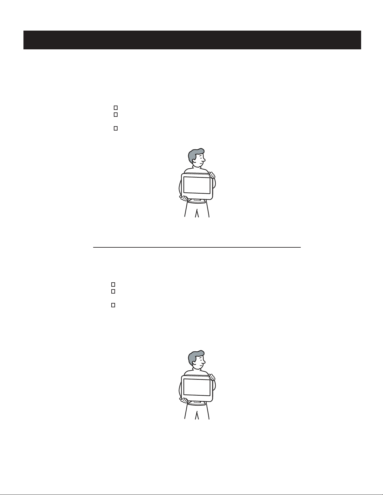
CARRYING THE TV
To avoid dropping the TV and causing serious injury, be sure to follow these guidelines:
Before carrying the TV, disconnect all cables.
When you carry the TV, place your hand as illustrated and hold it securely.
Do not put stress on the LCD panel.
When carrying the TV, do not subject it to shocks or vibration, or excessive force.
KDL-22L4000
TRANSPORTER LE TÉLEVISÉUR
Pour éviter d échapper le téleviséur et de causer des blessures graves, assurez-vous
de suivre ces directives:
Avant de transporter le téleviséur, débranchez tous les càbles.
Lorsque vous transportez le téleviséur, placez votre main tel qu’ illustré et tenez-le
fermement. N’imposez pas de charge sur le panneau ACL.
Lorsque vous transportez le téleviséur ne le soumettez pas à des chocs,
à des vibrations ou à une force excessive.
KDL-22L4000
7
Page 8
SAFETY-RELATED COMPONENT WARNING
KDL-22L4000
There are critical components used in LCD color TVs that are important for safety. These components are identifi ed with shading and
mark on the schematic diagrams and the electrical parts list. It is essential that these critical parts be replaced only with the part number
specifi ed in the electrical parts list to prevent electric shock, fi re, or other hazard.
NOTE: Do not modify the original design without obtaining written permission from the manufacturer or you will void the original parts and
labor guarantee.
!
USE CAUTION WHEN HANDLING THE LCD PANEL
When repairing the LCD panel, be sure you are grounded by using a wrist band.
When installing the LCD panel on a wall, the LCD panel must be secured using the 4 mounting holes on the rear cover.
To avoid damaging the LCD panel:
do not press on the panel or frame edge to avoid the risk of electric shock.
do not scratch or press on the panel with any sharp objects.
do not leave the module in high temperatures or in areas of high humidity for an extended period of time.
do not expose the LCD panel to direct sunlight.
avoid contact with water. It may cause a short circuit within the module.
disconnect the AC adapter when replacing the backlight (CCFL) or inverter circuit.
(High voltage occurs at the inverter circuit at 650Vrms.)
always clean the LCD panel with a soft cloth material.
use care when handling the wires or connectors of the inverter circuit. Damaging the wires may cause a short.
protect the panel from ESD to avoid damaging the electronic circuit (C-MOS).
LEAKAGE CURRENT HOT CHECK CIRCUIT
KDL-22L4000
8
Page 9
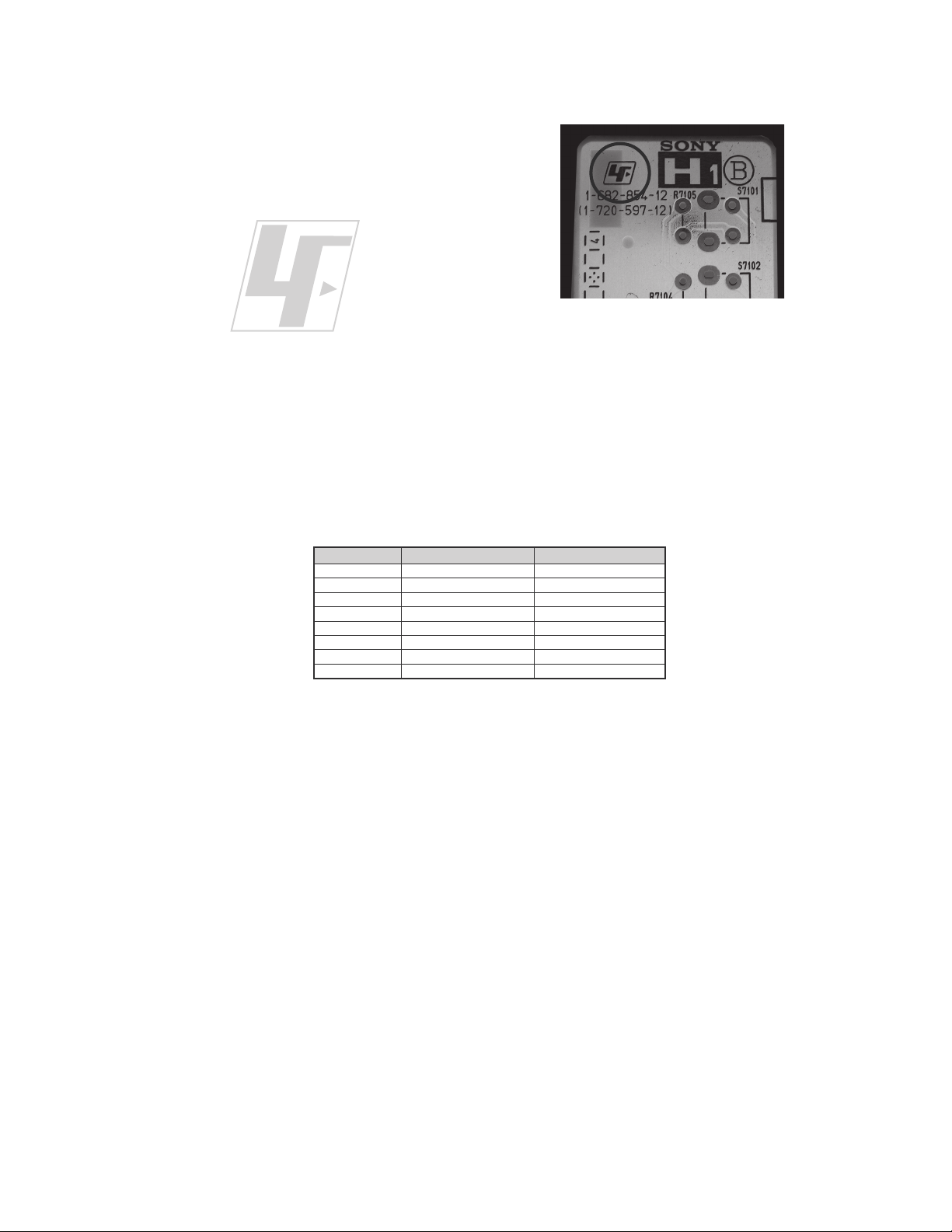
The circuit boards used in these models have been processed using
Lead Free Solder. The boards are identified by the LF logo located
close to the board designation e.g. H1 etc [ see example ]. The
servicing of these boards requires special precautions to be taken as
outlined below.
KDL-22L4000
example 1
It is strongly recommended to use Lead Free Solder material in order to guarantee optimal quality of new solder joints.
Lead Free Solder is available under the following part numbers :
rebmuntraP retemaiD skrameR
91-500-046-7mm3.0gK52.0
02-500-046-7mm4.0gK05.0
12-500-046-7mm5.0gK05.0
22-500-046-7mm6.0gK52.0
32-500-046-7mm8.0gK00.1
42-500-046-7mm0.1gK00.1
52-500-046-7mm2.1gK00.1
62-500-046-7mm6.1gK00.1
Due to the higher melting point of Lead Free Solder the soldering iron tip temperature needs to be set to 370 degrees centigrade.
This requires soldering equipment capable of accurate temperature control coupled with a good heat recovery characteristics.
For more information on the use of Lead Free Solder, please refer to
http://www.sony-training.com
KDL-22L4000
9
Page 10

SAFETY CHECK-OUT
KDL-22L4000
After correcting the original service problem, perform the following
safety checks before releasing the set to the customer:
1. Check the area of your repair for unsoldered or poorly soldered
connections. Check the entire board surface for solder splashes and
bridges.
2. Check the interboard wiring to ensure that no wires are “pinched” or
touching high-wattage resistors.
3. Check that all control knobs, shields, covers, ground straps, and
mounting hardware have been replaced. Be absolutely certain that
you have replaced all the insulators.
4. Look for unauthorized replacement parts, particularly transistors,
that were installed during a previous repair. Point them out to the
customer and recommend their replacement.
5. Look for parts which, though functioning, show obvious signs of
deterioration. Point them out to the customer and recommend their
replacement.
6. Check the line cords for cracks and abrasion. Recommend the
replacement of any such line cord to the customer.
7. Check the antenna terminals, metal trim, “metallized” knobs, screws,
and all other exposed metal parts for AC leakage. Check leakage as
described below.
The AC leakage from any exposed metal part to earth ground and
from all exposed metal parts to any exposed metal part having a
return to chassis, must not exceed 0.5 mA (500 microamperes).
Leakage current can be measured by any one of three methods.
1. A commercial leakage tester, such as the Simpson 229 or RCA
WT-540A. Follow the manufacturers’ instructions to use these
instructions.
2. A battery-operated AC milliampmeter. The Data Precision 245
digital multimeter is suitable for this job.
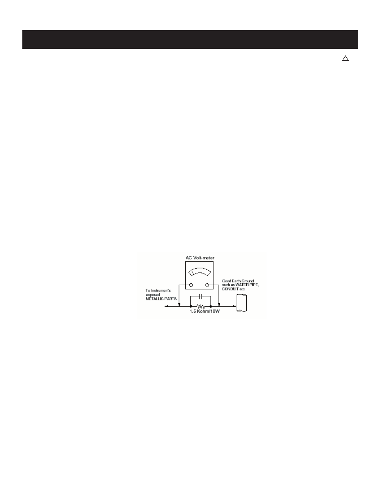
3. Measuring the voltage drop across a resistor by means of a VOM
or battery-operated AC voltmeter. The “limit” indication is 0.75
V, so analog meters must have an accurate low voltage scale.
The Simpson’s 250 and Sanwa SH-63TRD are examples of
passive VOMs that are suitable. Nearly all battery-operated digital
multimeters that have a 2 VAC range are suitable (see Figure A).
How to Find a Good Earth Ground
A cold-water pipe is a guaranteed earth ground; the cover-plate
retaining screw on most AC outlet boxes is also at earth ground. If the
retaining screw is to be used as your earth ground, verify that it is at
ground by measuring the resistance between it and a cold-water pipe
with an ohmmeter. The reading should be zero ohms.
If a cold-water pipe is not accessible, connect a 60- to 100-watt
trouble- light (not a neon lamp) between the hot side of the receptacle
and the retaining screw. Try both slots, if necessary, to locate the hot
side on the line; the lamp should light at normal brilliance if the screw
is at ground potential (see Figure B).
Leakage Test
0.15 F
Figure A. Using an AC voltmeter to check AC leakage. Figure B. Checking for earth ground.
To Exposed Metal
Parts on Set
Earth Ground
AC
Voltmeter
(0.75V)
Trouble Light
AC Outlet Box
Ohmmeter
Cold-water Pipe
KDL-22L4000
10
Page 11
KDL-22L4000
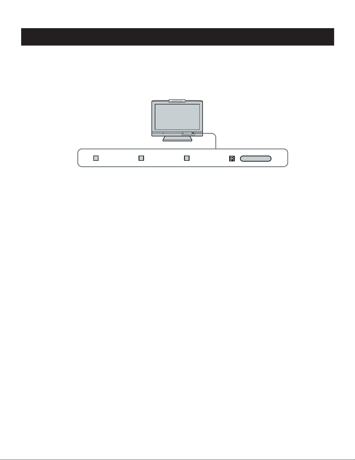
SELF-DIAGNOSTIC FUNCTION
IMPORTANT:
The units in this manual DO NOT contain a self-diagnostic function. If an error occurs, the TV will not stay on. It is our recommendation that if a repair
is required for these sets, the technician should bring both the A Board and the G Board to the customer location.
Control Buttons
4)-%2 34!.$"9 0/7%2
Description of LED Indictors
The units in this manual DO NOT contain a self-diagnostic function.
KDL-22L4000
11
Page 12
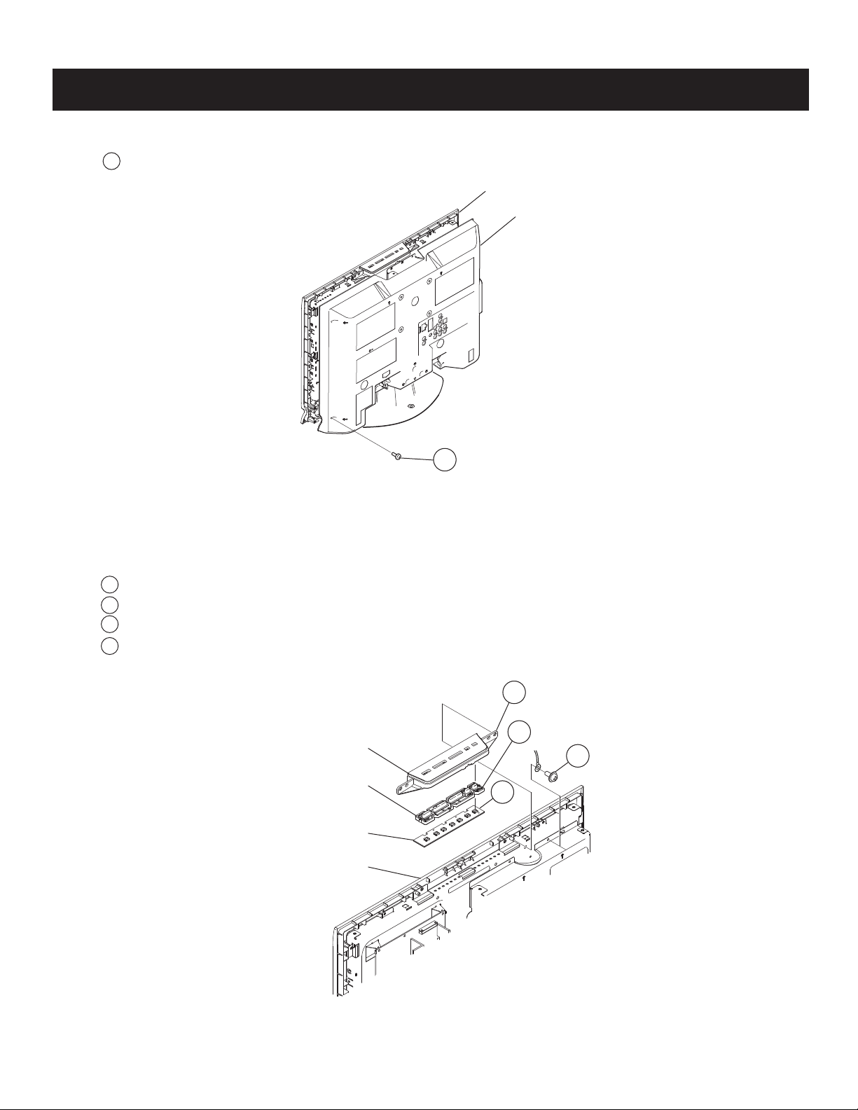
1-1. REAR COVER REMOVAL
1
Remove 13 screws from Rear Cover
KDL-22L4000
SECTION 1: DISASSEMBLY
Bezel
Rear Cover
1-2. FUNCTION KEY AND H1 BOARD REMOVAL
1
Slide out Function Key unit from Bezel
2
Release hooks and remove Function Key and H1 Board
3
Disconnect 1 connector
4
Remove 1 screw and release ground wire
Key Cover
Function Key
H1 Board
Bezel
1
1
2
4
3
KDL-22L4000
12
Page 13
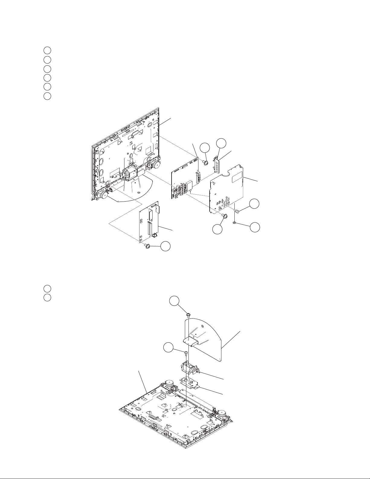
1-3. A BOARD AND G BOARD REMOVAL
1
Remove 2 HEX screws
2
Remove Hexagon Nut from tuner
3
Remove 8 screws from Main Shield
4
Release hooks and slide out Side Bracket
5
Disconnect 6 connectors and remove 7 screws from A Board
Disconnect 5 connectors and remove 5 screws from G Board
6
KDL-22L4000
Main Bracket
A Board
G Board
6
4
5
Side Jack Bracket
3
1
2
1-4. TABLE-TOP STAND ASSEMBLY AND UNDER COVER REMOVAL
1
Remove 3 screws
2
Remove 3 screws
1
Main Shield
KDL-22L4000
Ta bl e -To p
Stand Assembly
2
Main Bracket
Under Cover
Bottom Frame
13
Page 14
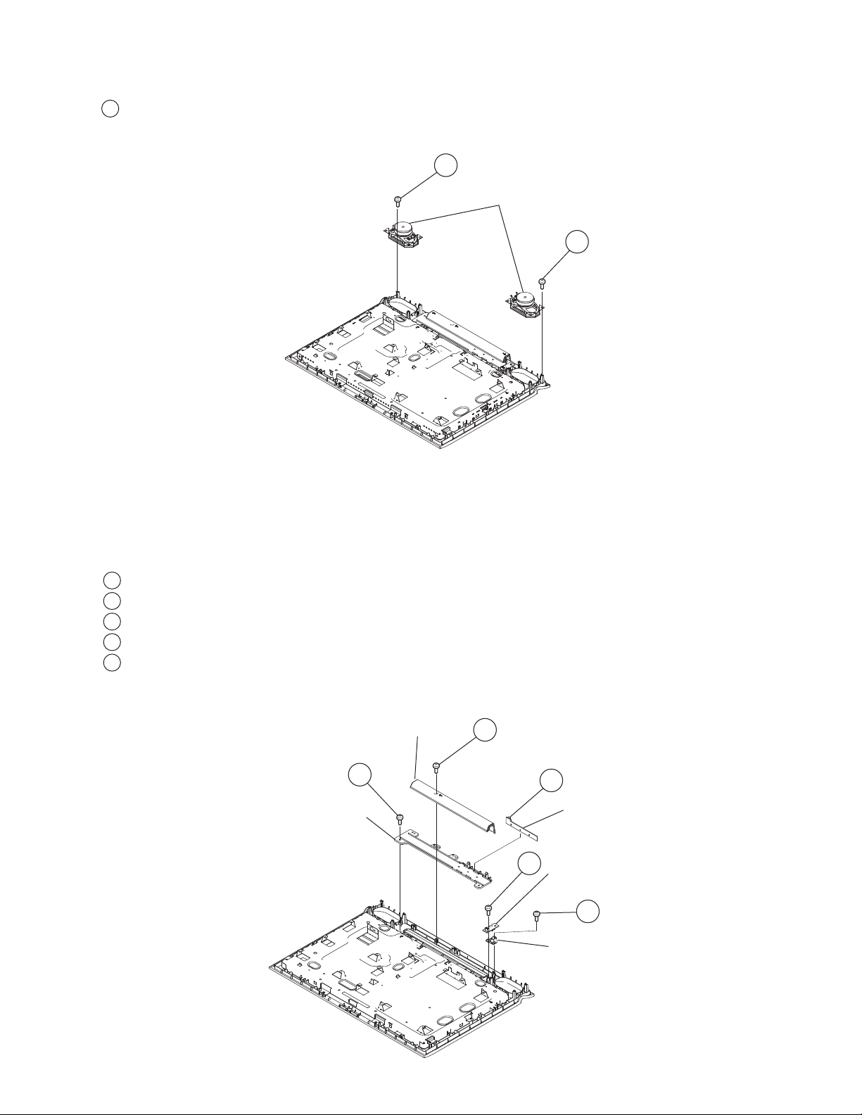
1-5. LOUDSPEAKER REMOVAL
1
Remove 6 screws from each Speaker
KDL-22L4000
1
Speakers
1
1-6. BOTTOM COVER, H2 BOARD, H3 BOARD, IR LENS AND LED LENS REMOVAL
1
Remove 1 screw from Bottom Cover
2
Disconnect 1 connector and slide out H3 (LED) Board
3
Disconnect 1 connector and remove 1 screw from H2 (IR) Board
4
Remove 1 screw from IR Lens and slide out from Bezel
5
Remove 2 screws from LED Lens
Bottom Cover
5
LED Lens
1
2
H3 Board
3
H2 Board
4
IR Lens
KDL-22L4000
14
Page 15
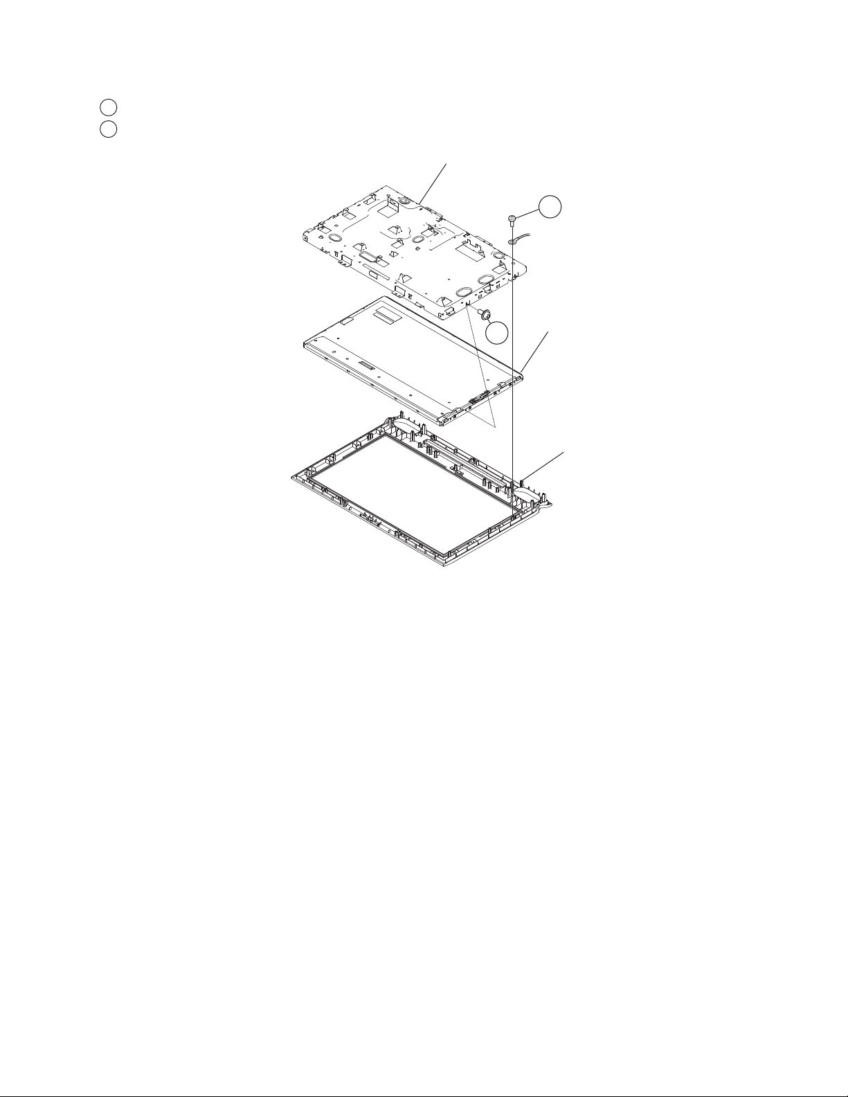
1-7. LCD PANEL REMOVAL
1
Remove 2 screws from Main Bracket and Bezel
Remove 4 screws and release LCD panel from Main Bracket
2
Main Bracket
2
KDL-22L4000
1
LCD Panel
Bezel
1-7-1. CLEANING THE LCD PANEL
CAUTION: When cleaning the TV, be sure to unplug the power cord to avoid any chance of electric shock.
Clean the cabinet of the TV with a dry soft cloth.
Wipe the LCD screen gently with a soft cloth.
→ Stubborn stains may be removed with a cloth slightly moistened with a solution of mild soap and warm water.
→ If using a chemically pretreated cloth, please follow the instruction provided on the package.
→ Never use strong solvents such as a thinner, alcohol or benzine for cleaning.
→ Periodic vacuuming of the ventilation openings is recommended to ensure to proper ventilation.
KDL-22L4000
15
Page 16
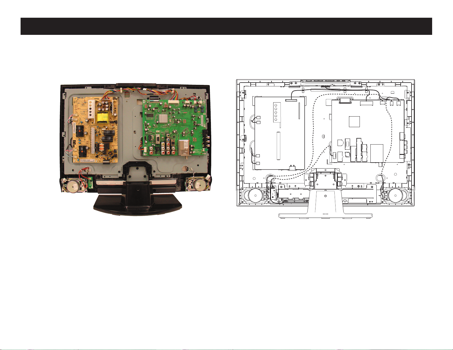
WIRE DRESSING
OVERALL VIEW
KDL-22L4000
CN202
CN201
CN204
CN203
CN1101
CN13
CN9
CN3
CN12
CN15 CN16
KDL-22L4000
16
Page 17
SECTION 2: SERVICE ADJUSTMENTS
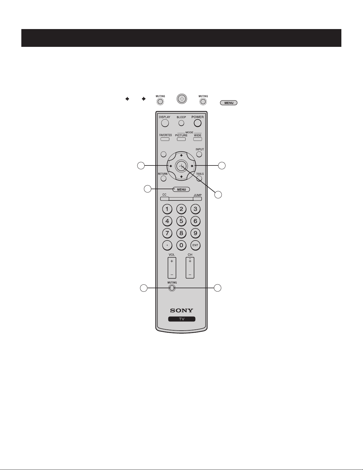
2-1. ACCESSING SERVICE (FACTORY) MODE
Use the remote commander to access Service (Factory) mode after completing a repair to the TV set.
1. TV must be in standby mode. (Power on) mode.
2. To display the service menu, quickly press the following buttons on the Remote Commander:
➔ ➔ ➔ ➔ ➔
KDL-22L4000
1
6
3
2
4
5
KDL-22L4000
RM-YD025
17
Page 18
KDL-22L4000
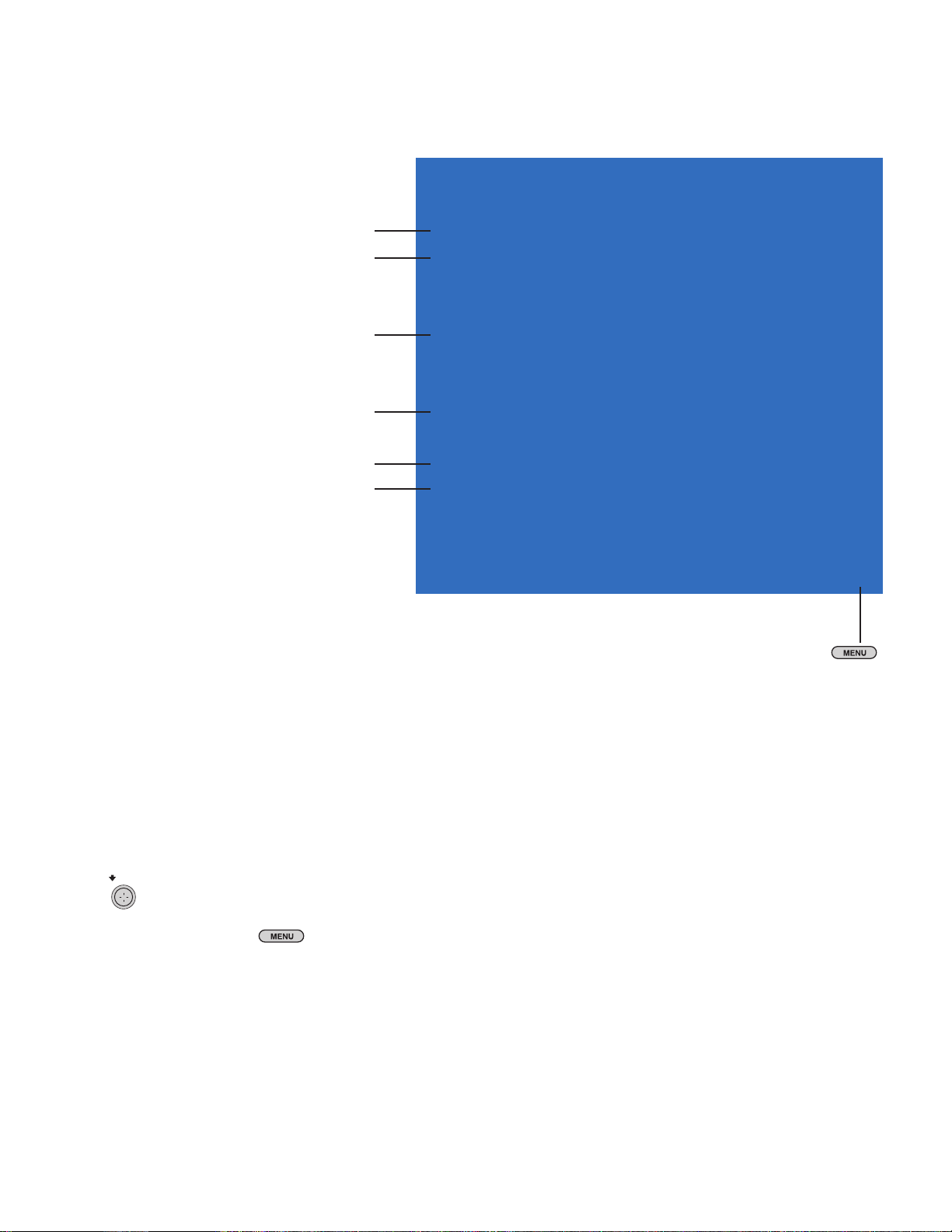
2-2. REVIEWING SERVICE (FACTORY) MODE
All of the necessary adjustment are contained in the boards for these models, therefore the following information is for informational purposes.
Factory Mode
Change source between
Video1,Video2 ,Component, PC, HDMI, & TV
Set “On” for White Balance adjust
Input Source <[ TV ]>
White Balance <[ Off ]>
Internal Pattern <[ 20 ]>
Color Temp.... >>
Set “On” for Aging mode start
Set “Off” to end aging mode.
Aging Mode <[ Off ]>
ADC Calibration >>
Auto Phase <[ Off ]>
Reset to Factory Defaults
Reset TV to Factory Defauts without resetting
Parental lock , Channel lists and other User settings.
To scan preset channels from
cable or antenna
Factory Reset <[ Off ]>
EDED WP <[ Protection ]>
User Reset <[ Off ]>
Recall Preset Ch <[ Off ]>
[</>]Set[EXIT]Exit
To Exit Service Mode, press
2-3. RESETTING TO FACTORY DEFAULTS AFTER BOARD REPLACEMENT
Traditional Service Mode is not available in this chassis, however, after replacing a board you should reset all of the settings to the Factory Default
from Service (Factory) Mode.
CAUTION: Resetting the
contact the customer to determine what adjustments they have made.
1. TV must be in Service (Factory) Mode.
2. Press
3. Press
4. When the Reset is complete, the text changes to No.
5. To exit “service mode”, press the
to select Factory Reset.
to select Yes.
TV to the Factory Defaults will over-write all customer settings including Parental Lock setting. Before performing this reset,
button
KDL-22L4000
18
Page 19

2-4. VIEWING MODEL INFORMATION
Use the Setup settings menu to display information about the TV.
1. TV must be On.
2. Press the
button to display the User Menus.
KDL-22L4000
Setup
Closed Captions (CC)
Info Banner
Label Video Inputs
Language
Sleep Timer
Power Saving
Product Information
CineMotion
Off
On
English
Off
Off
Off
TV
3. Press until the Settings icon is selected,
and then press
4. Press
until Product Information is selected, and then press .
Setup
Product Information
1: LD:-32L4000
2: XXXXXXXX
3: v1.001
4: RRT01
.
TV
Model Name
Serial Number of TV
Software Version
RRT Closed Caption Information
5. To exit, press the button
KDL-22L4000
19
Page 20

3-1. CIRCUIT BOARDS LOCATION
KDL-22L4000
SECTION 3: DIAGRAMS
A
H1
G
H3 (LED)
3-2. PRINTED
WIRING BOARDS AND
SCHEMATIC DIAGRAMS INFORMATION
All capacitors are in μF unless otherwise noted. pF : μμF 50WV or
less are not indicated except for electrolytics and tantalums.
All electrolytics are in 50V unless otherwise specifi ed.
All resistors are in ohms. kΩ=1000Ω, MΩ=1000kΩ
Indication of resistance, which does not have one for rating
electrical power, is as follows: Pitch : 5mm
Rating electrical power :
1
/
W in resistance, 1/
4
W and 1/
10
W in chip resistance.
16
: nonfl ammable resistor
: fusible resistor
: internal component
: panel designation and adjustment for repair
: earth ground
: earth-chassis
All variable and adjustable resistors have characteristic curve B,
unless otherwise noted.
Readings are taken with a color-bar signal input.
Readings are taken with a 10MΩ digital multimeter.
Voltages are DC with respect to ground unless otherwise noted.
Voltage variations may be noted due to normal production
tolerances.
1
/
W
4
H2 (IR)
All voltages are in V.
S : Measurement impossibility.
: B+line.
: B-line. (Actual measured value may be different).
: signal path. (RF)
Circled numbers are waveform references.
The components identifi ed by shading and ! symbol are critical for safety. Replace
only with part number specifi ed.
The symbol indicates a fast operating fuse and is displayed on the component
side of the board. Replace only with fuse of the same rating as marked.
!
Les composants identifi es per un trame et une marque
securite. Ne les remplacer que par une piece portant le numero specifi e.
Le symbole indique une fusible a action rapide. Doit etre remplace par une
fusible de meme yaleur, comme maque.
NOTE: The components identifi ed by a red outline and a mark contain confi dential
information. Specifi c instructions must be adhered to whenever these components
are repaired and/or replaced.
See Appendix A: Encryption Key Components in the back of this manual.
sont critiques pour la
KDL-22L4000
20
Page 21

KDL-22L4000
REFERENCE INFORMATION
RESISTOR
: RN METAL FILM
: RC SOLID
: FPRD NONFLAMMABLE CARBON
: FUSE NONFLAMMABLE FUSIBLE
: RW NONFLAMMABLE WIREWOUND
: RS NONFLAMMABLE METAL OXIDE
: RB NONFLAMMABLE CEMENT
: ADJUSTMENT RESISTOR
COIL
: LF-8L MICRO INDUCTOR
CAPACITOR
: TA TANTALUM
: PS STYROL
: PP POLYPROPYLENE
: PT MYLAR
: MPS METALIZED POLYESTER
: MPP METALIZED POLYPROPYLENE
: ALB BIPOLAR
: ALT HIGH TEMPERATURE
: ALR HIGH RIPPLE
Terminal name of semiconductors in silk screen
printed circuit ( )
Device Printed symbol Terminal name
Transistor
1
Transistor
2
3
Diode
4
Diode
Diode
5
Diode
6
Diode
7
8
Diode
Diode
9
Diode
0
Diode
!¡
Diode
!™
Transistor
!£
(FET)
Transistor
!¢
(FET)
Transistor
!?
(FET)
Transistor
!§
Transistor
!¶
Transistor
!•
Transistor
!ª
Transistor
@º
Transistor
@¡
Transistor
@™
Transistor
@£
Discrete semiconductot
–
(Chip semiconductors that are not actually used are included.)
*
Collector
Base
Collector
Base
Cathode
Cathode
Anode
Cathode
Anode
Common
Anode
Common
Anode Cathode
Common
Anode
Common
Anode Anode
Common
Cathode
Common
Cathode
Anode
Anode
Cathode
Drain
Drain
B1 E1
C2
B2 C1E2
B2 E2
C1
B1 C2
E1
B2 E2
C1
B1 C2E1
B2 E2
C1
B1 C2E1
E2
B1 E1
C2
(B2)
E1
B1
C1
(B2)
E1
E2
C2
Emitter
Emitter
Anode
(NC)
(NC)
Cathode
Anode
Cathode
Cathode
Cathode
Anode
Anode
Source
Gate
Source
Gate
Source
Drain
Gate
Emitter
Collector
Base
C1(B2)
E2
C2
B1
C1
Circuit
D
G
D
S
B1
B1
B1
B1
B1
B1
D
G
S
S
D
G
C1
E1
C1
E1
E1
C1
E2
C1
C1
G
S
C2
B2
E2
C2
B2
E2
E2
B2
C2
C2C1(B2)
E2
E2E1(B2)
C2
C2E1(B2)
C2
Ver.1.6
KDL-22L4000
21
Page 22

3-3. BLOCK DIAGRAM
H2
Board
H3 Board
H1 Board
CN5
CN6
1X4
HDMI IN
CN24
CN7
VGA AUDIO IN
CN21
VGA IN
CN10
VIDEO 2 AUDIO R/L
USB2.0
Code download/debug U0TX/RX
U16
A Board
CN13
IR/LED
CN12
KEY PAD
DV33
U11
AT24C32
24C02
U15
HDMI R/L
PC AUDIO IN
+5V
24C02
7
6
ADCX2;POWER X 1
I2C
HDMI IN
+5V
U21
12VA
HEF4052
CMO 21.6'
V216B1-L01
LVDS
U9
MT5380
DV10 DVRV
U22
NJM4558
DV33
CN9
1V3D
U30
NT5DS16M16CS-5T (GP)
16M x16
DDRI SDRAM
AL2/AR2
U14
DV33
MX25L32
SERIAL FLASH
DDRV
U20
I2S
STA559BW
U34
NJM4556
HEAD PHONE O/P
+12OPA_A
12V
U12
ALPS TDQU4-528A
SIDE INPUT
CN22
CN14
CN23
8 Ohm 5W
KDL-22L4000
TV IN
VIDEO 1 & AUDIO R/L
S-VIDEO IN
OR OPTION CN2
HEADPHONE OUT
CN20
CN11
KDL-22L4000
VIDEO 2
COMPONENT 1
COMPONENT1 AUDIO R/L
LINE OUT
CN18
CN1
8 Ohm 5W
22
Page 23

3-4. SCHEMATICS AND SUPPORTING INFORMATION
A BOARD SCHEMATIC DIAGRAM (1 OF 21)
1 | 2 | 3 | 4 | 5 | 6 | 7 | 8 | 9 | 10 | 11 | 12 | 13 | 14 | 15 | 16 | 17 | 18 | 19 | 20 |
A
—
B
—
C
—
KDL-22L4000
D
—
E
—
F
—
G
—
H
SWITCH POWER: 5.5V-->SW_55V
5.5V
22KR3J-L-GPR122KR3J-L-GP
12
R1
+3V3SB
12
R3
R3
10KR2J-3-GP
10KR2J-3-GP
R4
R4
1 2
47KR2J-2-GP
47KR2J-2-GP
OPWRSB[7,8]
Power on
10KR2J-3-GPR610KR2J-3-GP
12
R6
R5
R5
1 2
47KR2J-2-GP
47KR2J-2-GP
OPWRSB_Q3
1
PMBS3904-1-GP
PMBS3904-1-GP
POWER_ON_MOS
3
Q3
Q3
2
SC1U16V5KX-3GPC1SC1U16V5KX-3GP
C1
12
POWER_ON_SW_1
POWER_ON_SW
12
C5
C5
SC1U10V3KX-4GP
SC1U10V3KX-4GP
1
PMBS3904-1-GP
PMBS3904-1-GP
1
2
3
4 5
12
R2
R2
2K2R3J-1-GP
2K2R3J-1-GP
POWER_ON_SW_01
3
Q2
Q2
2
Q1
Q1
S
S
S
S
S
S
GD
GD
AO4435-GP
AO4435-GP
D
D
8
D
D
7
D
D
6
E100U16VM-25-GP
E100U16VM-25-GP
C501
C501
12
SW_55V
12
C2
SCD1U25V3KX-GPC2SCD1U25V3KX-GP
SW_55V
L1
L1
12
HCB3216KF-121T40-GP
HCB3216KF-121T40-GP
SW_55V_IN_U1
SCD1U16V2KX-3GPC3SCD1U16V2KX-3GP
SW_55V-->AV25
U1
U1
VIN3GND
VOUT
1
2
E100U16VM-25-GP
E100U16VM-25-GP
C503
C503
12
C3
12
G1117-25T63UF-GP
G1117-25T63UF-GP
12
C502
C502
E100U16VM-25-GP
E100U16VM-25-GP
AV25
SCD1U16V2KX-3GPC4SCD1U16V2KX-3GP
C4
12
SW_55V-->AV33
U2
U2
G1117-33T63UF-GP
G1117-33T63UF-GP
—
I
—
J
—
K
—
L
—
5.5V
L3
L3
HCB3216KF-121T40-GP
HCB3216KF-121T40-GP
12
SCD1U16V2KX-3GPC8SCD1U16V2KX-3GP
5.5V_IN_U3
C8
12
VIN3GND
VOUT
1
2
AV33_U88_ADJ
SW_55V
R292
L2
L2
HCB3216KF-121T40-GP
HCB3216KF-121T40-GP
U3
U3
G1117-33T63UF-GP
G1117-33T63UF-GP
VIN3GND
VOUT
1
2
+3V3SB
E100U16VM-25-GP
E100U16VM-25-GP
C506
C506
12
E100U16VM-25-GP
E100U16VM-25-GP
C507
C507
12
SCD1U16V2KX-3GPC9SCD1U16V2KX-3GP
C9
12
HCB3216KF-121T40-GP
HCB3216KF-121T40-GP
SW_55V_IN_U10
12
L4
L4
12
SCD1U16V2KX-3GP
SCD1U16V2KX-3GP
C10
C10
12
R292
1 2
4D7RJ-GP-U
4D7RJ-GP-U
E100U16VM-25-GP
E100U16VM-25-GP
C508
C508
12
SW_55V_IN_U101
U4
U4
G1117-33T63UF-GP
G1117-33T63UF-GP
VIN3GND
VOUT
1
2
E100U16VM-25-GP
SCD1U16V2KX-3GPC6SCD1U16V2KX-3GP
C6
12
E100U16VM-25-GP
C504
C504
12
SW55V-->DV33
DV33_OUTSW_55V_IN_U11
E100U16VM-25-GP
E100U16VM-25-GP
C509
C509
12
SCD1U16V2KX-3GP
SCD1U16V2KX-3GP
C11
C11
12
E100U16VM-25-GP
E100U16VM-25-GP
12
C505
C505
SCD1U16V2KX-3GPC7SCD1U16V2KX-3GP
DV33SW_55V
C7
12
AV33
M
—
N
A 1/21
—
DC CONVERTER 1
O
—
1-857-229-A <L4> A-P1
P
KDL-22L4000 23
Page 24

A BOARD SCHEMATIC DIAGRAM (2 OF 21)
1 | 2 | 3 | 4 | 5 | 6 | 7 | 8 | 9 | 10 | 11 | 12 | 13 | 14 | 15 | 16 | 17 | 18 | 19 | 20 |
A
—
B
—
C
—
KDL-22L4000
D
—
E
—
F
—
G
—
H
SW_55V--> +5V FOR PANEL USE
U17
U17
LD29150PT-GP
5.5V
5.5V
L5
L5
1 2
HCB3216KF-121T40-GP
HCB3216KF-121T40-GP
R10
R10
100R3J-4-GP
100R3J-4-GP
LD2951_01
LD2951_01
12
R14
R14
DUMMY-R2
DUMMY-R2
1 2
SW_55V_IN_IC4
C511
C511
12
E100U16VM-25-GP
E100U16VM-25-GP
LD29150PT-GP
INPUT4INH
3
5
12
C14
C14
SCD1U25V3KX-GP
SCD1U25V3KX-GP
TO263
ADJ/NC#1
OUTPUT2GND
1
+5V_IC4_ADJ
12
R15
R15
887R3-GP
887R3-GP
12
R12
R12
2K8R2F-GP
2K8R2F-GP
SCD1U25V3KX-GP
SCD1U25V3KX-GP
2.5V-->DV10_IN FOR 5380 USE
DV33
R379
R379
D51RJ-GP
D51RJ-GP
R400
R400
D51RJ-GP
D51RJ-GP
2.5V
12
D67
D67
AK
RGP20A-E3-23-GP
RGP20A-E3-23-GP
12
R7
R7
1 2
1KR3J-L1-GP
1KR3J-L1-GP
R8
DV10_IN
12
R9
R9
910R2F-1-GP
+5V
12
C13
C13
12
C510
C510
E470U16VM-L8-GP
E470U16VM-L8-GP
910R2F-1-GP
12
R11
R11
2KR2F-3-GP
2KR2F-3-GP
G966_FB
U5
U5
7
ADJ
5
NC#5
8
GND
9
GND
G966A-25ADJF11U-GP
G966A-25ADJF11U-GP
POK
VEN
VPP
VIN
VO
1
2
4
2.5V_G966A_1.1V_1
3
6
SCD1U16V2KX-3GP
SCD1U16V2KX-3GP
C16
C16
12
R8
1 2
4K7R2J-2-GP
4K7R2J-2-GP
G966_VEN_1
G966_5.5V_2
DV10_IN
E470U16VM-L8-GP
E470U16VM-L8-GP
C513
C513
12
C538
C538
G966_5.5V_1
12
C12
C12
12
E100U16VM-25-GP
E100U16VM-25-GP
SCD1U16V2KX-3GP
SCD1U16V2KX-3GP
12
C15
C15
12
2
SCD1U16V2KX-3GP
SCD1U16V2KX-3GP
L6
L6
1 2
HCB2012KF-121T50-GP
HCB2012KF-121T50-GP
C512
C512
E470U16VM-L8-GP
E470U16VM-L8-GP
R399
R399
1 2
100R3J-4-GP
100R3J-4-GP
1
D54
D54
BAV70-F-GP
BAV70-F-GP
3
2.5V_G966A_1.1V
5.5V
—
I
—
J
—
K
—
L
—
12VA--> +5V_TUNER FOR TUNER USE
U18
U18
VOUT2VIN3ADJ/GND
1
IC2_GND
R20
R20
1 2
0R2J-2-GP
0R2J-2-GP
C17
C17
12
E470U16VM-L8-GP
E470U16VM-L8-GP
+5V_TUNER
SCD1U16V2KX-3GP
SCD1U16V2KX-3GP
C18
C18
12
12VA
R16
R16
1 2
10RJ-2-GP-U
10RJ-2-GP-U
R17
R17
1 2
10RJ-2-GP-U
10RJ-2-GP-U
AP1084D50G-13-GP
AP1084D50G-13-GP
+12V_IC210+12V_R1846
E470U16VM-L8-GP
C21
C21
12
E470U16VM-L8-GP
1 2
120R3F-L-GP
120R3F-L-GP
12
R19
R19
0R2J-2-GP
0R2J-2-GP
IC2_GND1
R18
R18
NC
NC
SW_55V-->AV12_IN FOR 5380 USE
U6
U6
G1117T63UF-GP
G1117T63UF-GP
IN3ADJ/GND1OUT
SW_55V
R366
R366
1 2
4D7RJ-GP-U
4D7RJ-GP-U
5.5V_IN_U21
R392
R392
1 2
4D7RJ-GP-U
4D7RJ-GP-U
L7
L7
HCB3216KF-121T40-GP
HCB3216KF-121T40-GP
12
5.5V_IN_U2
12
C514
C514
E470U16VM-L8-GP
E470U16VM-L8-GP
SCD1U16V2KX-3GP
SCD1U16V2KX-3GP
C19
C19
12
2
AV12
AV12
E100U16VM-25-GP
E100U16VM-25-GP
C515
C515
12
SCD1U16V2KX-3GP
SCD1U16V2KX-3GP
C20
C20
12
M
—
N
A 2/21
—
DC CONVERTER 2
O
—
1-857-229-A <L4> A-P2
P
KDL-22L4000 24
Page 25

A BOARD SCHEMATIC DIAGRAM (3 OF 21)
1 | 2 | 3 | 4 | 5 | 6 | 7 | 8 | 9 | 10 | 11 | 12 | 13 | 14 | 15 | 16 | 17 | 18 | 19 | 20 |
A
—
B
—
C
—
KDL-22L4000
D
—
E
—
F
—
G
—
SW_55V
L8
L8
12
HCB3216KF-121T40-GP
HCB3216KF-121T40-GP
SW_55V_IN_DDRV1
12
10RJ-2-GP-U
10RJ-2-GP-U
R43
R43
12
R407
R407
10RJ-2-GP-U
10RJ-2-GP-U
SW_55V_IN_DDRV
SCD1U16V2KX-3GP
C517
C517
12
SCD1U16V2KX-3GP
E470U16VM-L8-GP
E470U16VM-L8-GP
U7
U7
APL1084UC-GP
APL1084UC-GP
1
C23
C23
12
DDRV_ADJ
12
INPUT3OUTPUT2ADJ/GND
R21
R21
12
110R3F-GP
110R3F-GP
12
R22
R22
120R2F-GP
120R2F-GP
C518
C518
E22U16VM-11-GP
E22U16VM-11-GP
Screw Hole
DDRV_IN
SCD1U16V2KX-3GP
E220U16VM-L8-GP
E220U16VM-L8-GP
C516
C516
12
C22
C22
12
SCD1U16V2KX-3GP
GP1
GP1
NP1
567
8
9
MISC-3041005800-GP-U1
MISC-3041005800-GP-U1
4
3
2
1
GP2
GP2
NP1
567
8
9
MISC-3041005800-GP-U1
MISC-3041005800-GP-U1
4
3
2
1
GP3
GP3
NP1
567
8
9
MISC-3041005800-GP-U1
MISC-3041005800-GP-U1
4
3
2
1
GP4
GP4
NP1
567
8
9
MISC-3041005800-GP-U1
MISC-3041005800-GP-U1
4
3
2
1
GP5
GP5
NP1
567
8
9
MISC-3041005800-GP-U1
MISC-3041005800-GP-U1
4
3
2
1
H
—
I
—
J
—
K
—
L
VTT
SCD1U16V2KX-3GP
SCD1U16V2KX-3GP
12
C24
C24
DDRV
R26
NCR26
NC
12
DUMMY-R2
DUMMY-R2
DUMMY-R2
DUMMY-R2
12
C25
C25
SC4D7U16V5KX-1-GP
SC4D7U16V5KX-1-GP
SCD1U16V2KX-3GP
R29
R29
NC
NC
12
SCD1U16V2KX-3GP
C29
C29
12
MEM_VREF
8
3
4
VTT
VSENSE
VREF
U8U8
12V
R23
R23
C393
C393
+12V_C210
1
12
12
24KR3-GP
24KR3-GP
R27
1
9
7
PVIN
GND
PGND
AVIN
VDDQ
SD#
6
5
2
MEM_VREF
U7_SD
SCD1U16V2KX-3GP
SCD1U16V2KX-3GP
12
C27
C27
R28
R28
12
4K7R2J-2-GP
4K7R2J-2-GP
DDRV
E220U16VM-L8-GP
E220U16VM-L8-GP
12
C519
C519
MEM_VREF [11]
DDRV
SCD1U16V2KX-3GP
SCD1U16V2KX-3GP
OPWM0[8]
C386
C386
12
C387
C387
12
R27
12
47KR2J-2-GP
47KR2J-2-GP
C389
C389
C388
C388
12
12
SCD1U16V2KX-3GP
SCD1U16V2KX-3GP
C390
C390
SCD1U16V2KX-3GP
SCD1U16V2KX-3GP
OPWM0_1
C391
C391
C392
C392
12
12
12
SCD1U16V2KX-3GP
SCD1U16V2KX-3GP
C26
C26
12
SC10U16V5ZY-GP
SC10U16V5ZY-GP
12
R24
R24
3KR3F-GP
3KR3F-GP
3
Q4
Q4
PMBS3904-1-GP
PMBS3904-1-GP
2
C394
C394
C395
C395
12
+12V_D202
3
C396
C396
12
D1
D1
BAV99-4-GP
BAV99-4-GP
C397
C397
12
1
SC10U10V5ZY-1GP
SC10U10V5ZY-1GP
C28
C28
12
2
C398
C398
12
12
12
C399
C399
12
R25
R25
47KR3J-L-GP
47KR3J-L-GP
C400
C400
ESD_N
C401
C401
12
12
SCD1U16V2KX-3GP
SCD1U16V2KX-3GP
—
M
—
N
—
O
—
P
SCD01U16V2KX-3GP
SCD01U16V2KX-3GP
SCD01U16V2KX-3GP
SCD01U16V2KX-3GP
SCD01U16V2KX-3GP
SCD01U16V2KX-3GP
SCD01U16V2KX-3GP
SCD01U16V2KX-3GP
SC470P50V2JN-GP
SC470P50V2JN-GP
SC1KP50V2KX-1GP
SC1KP50V2KX-1GP
SC1KP50V2KX-1GP
SC1KP50V2KX-1GP
SC1KP50V2KX-1GP
SC1KP50V2KX-1GP
SC1KP50V2KX-1GP
SC1KP50V2KX-1GP
SC1KP50V2KX-1GP
SC1KP50V2KX-1GP
SCD01U16V2KX-3GP
SCD01U16V2KX-3GP
A 3/21
DC CONVERTER 3
1-857-229-A <L4> A-P3
KDL-22L4000 25
Page 26

A BOARD SCHEMATIC DIAGRAM (4 OF 21)
1 | 2 | 3 | 4 | 5 | 6 | 7 | 8 | 9 | 10 | 11 | 12 | 13 | 14 | 15 | 16 | 17 | 18 | 19 | 20 |
A
—
B
—
C
—
D
—
E
—
F
—
1 L_DET
2 ON/OFF INV
3 DIMM
4+12
5+12
6GND
7 +5.5V
8 +5.5V
9GND
10 2.5V
11 2.5V
12 GND
13 E_DET
CN3
CN3
JWT-CON14-GP
JWT-CON14-GP
1
2
3
4
5
6
7
8
9
10
11
12
13
14
BL_ON/OFF
Dimming
POWER12_CN
PGND
POWER5V5_CN
PGND
POWER2V5_CN
PGND
R237
R237
1 2
SCD1U16V2KX-3GP
SCD1U16V2KX-3GP
12
C328
C328
L9 HCB2012KF-121T50-GPL9 HCB2012KF-121T50-GP
1 2
L10 HCB2012KF-121T50-GPL10 HCB2012KF-121T50-GP
1 2
L11 HCB2012KF-121T50-GPL11 HCB2012KF-121T50-GP
1 2
L12 HCB2012KF-121T50-GPL12 HCB2012KF-121T50-GP
1 2
L13 HCB2012KF-121T50-GPL13 HCB2012KF-121T50-GP
1 2
L14 HCB2012KF-121T50-GPL14 HCB2012KF-121T50-GP
AC_DET0
1 2
SCD1U16V2KX-3GP
SCD1U16V2KX-3GP
12
C327
C327
R107
R107
1KR2J-1-GP
1KR2J-1-GP
1 2
1KR2J-1-GP
1KR2J-1-GP
AC_DET
L_DET [8]
POWER12_IN
POWER55_IN
POWER25_IN
GND
AC_DET [8]
POWER12_IN
POWER55_IN
POWER25_IN
C520
C520
12
C31
C31
12
C33
C33
12
KDL-22L4000
12V
E470U16VM-L8-GP
E470U16VM-L8-GP
E470U16VM-L8-GP
E470U16VM-L8-GP
E470U16VM-L8-GP
E470U16VM-L8-GP
SCD1U25V2ZY-1GP
SCD1U25V2ZY-1GP
C30
C30
12
5.5V
12
C32
C32
SCD1U25V3KX-GP
SCD1U25V3KX-GP
12
C34
C34
SCD1U25V3KX-GP
SCD1U25V3KX-GP
3
D55
D55
2
BAV70-F-GP
BAV70-F-GP
1
R391
R391
4K7R3J-2-GP
4K7R3J-2-GP
12
2.5V
R401
R401
10KR3F-L-GP
10KR3F-L-GP
1 2
VCCRESET [8]
G
—
H
—
I
—
J
—
K
—
L
—
DV33
Q5
Q5
S
S
12V
E47U25VM-5-GP
E47U25VM-5-GP
12
47KR2J-2-GP
47KR2J-2-GP
R30
R30
12
R32
12VA_SW_1
1
PMBS3904-1-GP
PMBS3904-1-GP
R32
47KR2J-2-GP
47KR2J-2-GP
3
Q6
Q6
2
+3V3SB
12
R33
R33
10KR2J-3-GP
10KR2J-3-GP
R37
12VA_SW_0
R40
R40
OPWRSB_Q9
10KR2J-3-GP
10KR2J-3-GP
R41
R41
1 2
12
47KR2J-2-GP
47KR2J-2-GP
OPWRSB[4,8]
1
PMBS3904-1-GP
PMBS3904-1-GP
3
Q9
Q9
2
R37
1 2
47KR2J-2-GP
47KR2J-2-GP
C521
C521
12
12
12VA_SW_2
1
S
S
2
S
S
3
GD
GD
4 5
C522
C522
E100U16VM-25-GP
E100U16VM-25-GP
GPIO_1[8]
AO4435-GP
AO4435-GP
D
D
8
D
D
7
D
D
6
DV33
R34
R34
10KR2J-3-GP
10KR2J-3-GP
1 2
R39
R39
12
10KR2J-3-GP
10KR2J-3-GP
12VA
BL_ON/OFF_1
12
C37
C37
SC1U10V3KX-4GP
SC1U10V3KX-4GP
NC
NC
LVDSVDD
1
PMBS3904-1-GP
PMBS3904-1-GP
R35
R35
12
47KR3J-L-GP
47KR3J-L-GP
BL_ON/OFF
3
Q8
Q8
2
12
R31
R31
1KR2F-3-GP
1KR2F-3-GP
R36
R36
1 2
10KR3J-L1-GP
10KR3J-L1-GP
1
PMBS3904-1-GP
PMBS3904-1-GP
3
Q7
Q7
2
R38
R38
Dimming_1
OPWM1[8]
12
10KR2J-3-GP
10KR2J-3-GP
C36
C36
NC
NC
DUMMY-C2
DUMMY-C2
1 2
DimmingDimming_2
12
C35
C35
SC10U10V5ZY-1GP
SC10U10V5ZY-1GP
M
—
N
A 4/21
—
POWER CONN
O
—
1-857-229-A <L4> A-P4
P
KDL-22L4000 26
Page 27

A BOARD SCHEMATIC DIAGRAM (5 OF 21)
1 | 2 | 3 | 4 | 5 | 6 | 7 | 8 | 9 | 10 | 11 | 12 | 13 | 14 | 15 | 16 | 17 | 18 | 19 | 20 |
A
—
B
—
C
—
D
—
E
—
F
KDL-22L4000
2OF11
U9B
OSDA0[21]
OSCL0[21]
OSDA1[14]
OSCL1[14]
OPWM0[6]
OPWM1[7]
OPWM2[15]
TP1TPAD30 TP1TPAD30
ADIN4[19]
Tuner_AFT[10]
ADIN2[19]
1
TP26TPAD30 TP26TPAD30
OPWRSB[4,7]
OSDA0
OSCL0
OPWM2
GPIO_67
OXTALO
OXTALI
AVCC_SRV
AVDD33_XTAL
1
PWRDET
AVDD33_REG
C_XREG
ORESET#
OPWRSB
U9B
206
OSDA0
207
OSCL0
63
OSDA1
62
OSCL1
193
OPWM0
204
OPWM1
205
OPWM2
148
VCXO
145
XTALO
146
XTALI
149
AVDD33_SRV
147
AVDD33_XTAL
154
ADIN4
153
ADIN3
152
ADIN2
151
ADIN1
150
ADIN0
88
AVDD33_REG
87
C_XREG
71
ORESET#
72
OPWRSB
MT5380AU-GP
MT5380AU-GP
2OF11
GPIO_0
GPIO_1
GPIO_3
GPIO_4
GPIO_5
GPIO_6
GPIO_7
GPIO_8
GPIO_9
GPIO_10
GPIO_11
GPIO_12
GPIO_13
OPCTRL0
OPCTRL1
OPCTRL2
OPCTRL3
OPCTRL4
OPCTRL5
245
246
209
210
211
59
60
212
213
214
216
217
218
92
91
76
75
90
89
GPIO_0
GPIO_1
GPIO_3_1
SW_GPIO4
GPIO_5
GPIO_6
GPIO_7
GPIO_8
GPIO_9_1
GPIO_10_1
GPIO_11
GPIO_12
GPIO_13
SV1_DET
OPCTRL2
OPCTRL4
OPCTRL5
GPIO_0 [14,17]
GPIO_1 [7]
SW_GPIO4 [23]
L_DET [7]
GPIO_7 [14]
GPIO_8 [24]
LED_Amber(SLEEP) [19]
RESET_AMP [21]
GPIO_13 [16]
TUNER_SYNC [23]
AC_DET [7]
OPCTRL3 [19]
12
12
0R2J-2-GP
0R2J-2-GP
0R2J-2-GP
0R2J-2-GP
OPCTRL4 [15]
OPCTRL5 [15]
R274 100R2J-2-GPR274 100R2J-2-GP
R291 100R2J-2-GP
R291 100R2J-2-GP
12
1
R256
R256
R315
R315
12
R265
R265
100R2J-2-GP
100R2J-2-GP
NC
NC
TP27TP27
R243 0R2J-2-GPR243 0R2J-2-GP
LED_GREEN_POWER [19]
LED_RED(STANDBY) [19]
12
12
GPIO_3 [22]
HP_DET [22]
GPIO_9 [21]
OIRI [12,19]
—
G
—
H
—
I
—
J
—
DV33
R44
R44
1KR2J-1-GP
1KR2J-1-GP
12
PWRDET
C_XREG
DV33 DV33
R45
R45
4K7R2J-2-GP
4K7R2J-2-GP
12
OSDA0
R48
R48
C_XREG_01
12
0R2J-2-GP
0R2J-2-GP
R46
R46
4K7R2J-2-GP
4K7R2J-2-GP
12
OSCL0
12
C40
C40
SC4D7U10V5ZY-3GP
SC4D7U10V5ZY-3GP
U10
U10
1
GND
RESET#/RESET2MR#
G692L263TCUF-GP
G692L263TCUF-GP
VCC
R47
NCR47
NC
12
820KR2F-GP
820KR2F-GP
X1
X1
12
XTAL-60MHZ-2-GP
XTAL-60MHZ-2-GP
SC10P50V2JN-4GP
SC10P50V2JN-4GP
C41
C41
12
4
MCU_RESET_ISPORESET#
3
R402
R402
33K2R3F-GP
33K2R3F-GP
SCD1U25V2ZY-1GP
SCD1U25V2ZY-1GP
C39
C39
12
12
SC1KP50V2KX-1GP
SC1KP50V2KX-1GP
C38
C38
12
DV33
VCCRESET [7]
DV33
C42
C42
12
OXTALOOXTALI
SC10P50V2JN-4GP
SC10P50V2JN-4GP
L18
L18
12
XTAL_1
12
C43
C43
COIL-820NH-GP
COIL-820NH-GP
SC1000P50V3JN-GP
SC1000P50V3JN-GP
K
—
L
—
M
—
N
—
+3V3SB +3V3SB +3V3SB
L20
L19
L19
12
FCM1608CF-121T03-GP
FCM1608CF-121T03-GP
SC1U10V3KX-4GP
SC1U10V3KX-4GP
AVCC_SRV AVDD33_REG AVDD33_XTAL
FCM1608CF-121T03-GP
FCM1608CF-121T03-GP
SCD1U16V2KX-3GP
SCD1U16V2KX-3GP
C45
C44
C44
12
C45
12
L20
12
AVDD33_REG AVDD33_XTAL
C46
C46
12
SC1U10V3KX-4GP
SC1U10V3KX-4GP
SCD1U16V2KX-3GP
SCD1U16V2KX-3GP
C47
C47
12
FCM1608CF-121T03-GP
FCM1608CF-121T03-GP
L21
L21
12
C48
C48
12
SC1U10V3KX-4GP
SC1U10V3KX-4GP
C49
C49
SCD1U16V2KX-3GP
SCD1U16V2KX-3GP
12
12
SCD1U16V2KX-3GP
SCD1U16V2KX-3GP
C372
C372
U11
U11
1
2
3
AT24C32CN-SH-T-GP
AT24C32CN-SH-T-GP
VCC
A0
WP
A1
SCL
A2
GND4SDA
R50
8
OSD_WP_1 OSD_WP
7
6
5
OSCL0
OSDA0
R50
33R2J-2-GP
33R2J-2-GP
R49
R49
12
10KR2F-2-GP
10KR2F-2-GP
12
Q10
Q10
PMBS3904-1-GP
PMBS3904-1-GP
3
2
GPIO_0_OSD
1
R51
R51
12
47KR2J-2-GP
47KR2J-2-GP
GPIO_0 [14,17]
A 5/21
GPIO INTERFACE
O
—
1-857-229-A <L4> A-P5
P
KDL-22L4000 27
Page 28

A BOARD SCHEMATIC DIAGRAM (6 OF 21)
1 | 2 | 3 | 4 | 5 | 6 | 7 | 8 | 9 | 10 | 11 | 12 | 13 | 14 | 15 | 16 | 17 | 18 | 19 | 20 |
A
—
B
—
C
—
KDL-22L4000
D
—
E
—
F
—
G
—
H
USB_VRT
USB_DM
USB_DP
AVDD33_USB
AVDD12_USB
TP3
TP3
TP2
TP2
TPAD30
TPAD30
TPAD30
TPAD30
AV33
L22
L22
12
FCM1608CF-121T03-GP
FCM1608CF-121T03-GP
1
1
SC4D7U16V5ZY-GP
SC4D7U16V5ZY-GP
C50
C50
12
68
65
66
67
TP_01
TP_02
AVDD33_USB
69
159
160
SCD1U16V2KX-3GP
SCD1U16V2KX-3GP
U9D
U9D
USB_VRT
USB_DM
USB_DP
AVDD33_USB
AVDD12_USB
TP0
TN0
MT5380AU-GP
MT5380AU-GP
C51
C51
12
USB_VRT
4OF11
4OF11
AVDD12_ADCPLL
AVDD12_TVDPLL
AVDD12_HDMIPLL
AVDD12_APLL
AVDD12_SYSPLL
AVDD12_DMPLL
AVDD12_DTDPLL
R52
R52
12
5K1R2F-2-GP
5K1R2F-2-GP
162
157
155
163
161
158
156
AVDD12_PLL
USB_DP
USB_DM
R53 0R2J-2-GPR53 0R2J-2-GP
12
R54 0R2J-2-GPR54 0R2J-2-GP
12
USB_DP0
USB_DM0
56
CN5
CN5
4
3
2
1
FOX-USB-2-GP
FOX-USB-2-GP
—
I
—
J
—
K
—
L
AV12
L23
L23
12
FCM1608CF-121T03-GP
FCM1608CF-121T03-GP
C523
C523
E100U16VM-25-GP
E100U16VM-25-GP
12
AV12
12
FCM1608CF-121T03-GP
FCM1608CF-121T03-GP
C54
C54
SC1U10V3KX-4GP
SC1U10V3KX-4GP
12
L24
L24
AVDD12_USB
AVDD12_USB
SC4D7U16V5ZY-GP
SC4D7U16V5ZY-GP
C52
C52
12
C55
C55
C53
C53
12
AVDD12_PLL
12
SC4D7U16V5KX-1-GP
SC4D7U16V5KX-1-GP
SCD1U16V2KX-3GP
SCD1U16V2KX-3GP
C57
C57
C56
C56
SCD01U25V2KX-3GP
SCD01U25V2KX-3GP
12
12
SCD1U16V2KX-3GP
SCD1U16V2KX-3GP
+5V
F1
F1
1 2
FUSE-1A6V-2-GP
FUSE-1A6V-2-GP
USB+5V
USB_DP0 USB_DM0
USB+5V
12
C536
C536
E470U16VM-L8-GP
E470U16VM-L8-GP
3
BAV99-4-GP
BAV99-4-GP
D2
D2
USB+5V USB+5V
2
1
3
2
D3
D3
BAV99-4-GP
BAV99-4-GP
1
—
M
—
N
—
O
—
P
A 6/21
USB
1-857-229-A <L4> A-P6
KDL-22L4000 28
Page 29

A BOARD SCHEMATIC DIAGRAM (7 OF 21)
1 | 2 | 3 | 4 | 5 | 6 | 7 | 8 | 9 | 10 | 11 | 12 | 13 | 14 | 15 | 16 | 17 | 18 | 19 | 20 |
A
—
B
—
C
—
KDL-22L4000
D
—
E
—
F
—
G
—
H
—
I
MPX0P_1
MPX0N_1
12
R55
R55
0R5J-5-GP
0R5J-5-GP
AV25
C58
C58
C59
C59
TUNER_DATA
L94
L94
12
FCM1608K-151T06-GP
FCM1608K-151T06-GP
C61
C61
SC1U10V3KX-4GP
SC1U10V3KX-4GP
12
AVSS25_SADC
MPX0
12
SCD01U25V2KX-3GP
SCD01U25V2KX-3GP
12
SCD01U25V2KX-3GP
SCD01U25V2KX-3GP
TUNER_CLK
AVDD25_SADC
12
C62
C62
SC4D7U16V5KX-1-GP
SC4D7U16V5KX-1-GP
R66 0R2J-2-GPR66 0R2J-2-GP
12
NC
NC
U19
U19
1
INPUT
2
GROUND
3
OUTPUT
SFSRA4M50DF00-GP
SFSRA4M50DF00-GP
TP4TP4
MPX0P
MPX0N
TP_03
1
R58
R58
4K7R2J-2-GP
R57
R57
12
SCD1U16V2KX-3GP
SCD1U16V2KX-3GP
C65
C65
12
4K7R2J-2-GP
4K7R2J-2-GP
4K7R2J-2-GP
12
C63
C63
U9H
U9H
166
SIFP
168
SIFN
169
AF
197
TUNER_DATA
196
TUNER_CLK
MT5380AU-GP
MT5380AU-GP
U12
U12
+5V
12
SCD01U25V2KX-3GP
SCD01U25V2KX-3GP
TUNER-21P-10-GP
TUNER-21P-10-GP
MPX0P_1
8OF11
8OF11
AVDD25_SADC
AVSS25_SADC
RF_AGC
IF_AGC
VIDEO_OUTPUT
B2/ANALOG_+5V
T/P/TU_MONITOR
GND25GND24GND23GND
13
22
165
167
195
194
SIF_OUTPUT
B1/+5V
T/P/RF_AGC
NC#7
NC#1
T/P/A-IF_OUT
NC#19
SDA
IF_AGC
IF_OUT2
IF_OUT1
GND
GND
12
AVDD25_SADC
AVSS25_SADC
RF_AGC
1
IF_AGC1
4
3
8
2
5
6
AFT
7
1
11
16
AS
17
19
15
14
SCL
18
20
21
R56
R56
TP5TP5
12
10KR2J-3-GP
10KR2J-3-GP
VIDEO_OUT
+5V_TUNER_IF
+5V_TUNER_RF
Tuner_AFT_0
SIF_OUT
TUNER_DATA_T
TUNER_CLK_T
IF_AGC0
IF_AGC
SCD047U10V2KX-2GP
SCD047U10V2KX-2GP
C60
C60
12
C262
C262
SCD1U16V2KX-3GP
SCD1U16V2KX-3GP
SCD01U16V2KX-3GP
SCD01U16V2KX-3GP
12
SC1000P50V3JN-GP
SC1000P50V3JN-GP
SC1000P50V3JN-GP
SC1000P50V3JN-GP
12
C268
C268
C261
C261
12
IF-
IF+
L90 BLM18HE152SN1D-GPL90 BLM18HE152SN1D-GP
L91 BLM18HE152SN1D-GPL91 BLM18HE152SN1D-GP
12
C269
C269
R262
NC R262
NC
12
L87 BLM18HE152SN1D-GPL87 BLM18HE152SN1D-GP
12
L89 BLM18HE152SN1D-GPL89 BLM18HE152SN1D-GP
12
12
NC
NC
L86 BLM18HE152SN1D-GPL86 BLM18HE152SN1D-GP
12
12
R88
R88
68K1R2F-1-GP
68K1R2F-1-GP
L78 BLM18HE152SN1D-GPL78 BLM18HE152SN1D-GP
12
L77 BLM18HE152SN1D-GPL77 BLM18HE152SN1D-GP
12
L84 BLM18HE152SN1D-GPL84 BLM18HE152SN1D-GP
12
R264
R264
0R3-0-U-GP
0R3-0-U-GP
0R3-0-U-GP
0R3-0-U-GP
12
12
+5V_TUNER_IF1
SCD01U25V2KX-3GP
SCD01U25V2KX-3GP
12
C373
C373
C318
C318
12
+5V_TUNER_RF1
R64
Tuner_AFT_1
12
R64
12
0R2J-2-GP
0R2J-2-GP
DUMMY-R2
DUMMY-R2
TUNER_DATA1
TUNER_CLK1
C64
C64
SCD01U25V2KX-3GP
SCD01U25V2KX-3GP
MPX_0
L93 FCM1608K-151T06-GPL93 FCM1608K-151T06-GP
12
SCD1U16V2KX-3GP
SCD1U16V2KX-3GP
E470U16VM-L8-GP
E470U16VM-L8-GP
C525
C525
12
Tuner_AFT
12
R65
R65
R59
R59
12
4K7R2J-2-GP
4K7R2J-2-GP
SCD1U16V2KX-3GP
SCD1U16V2KX-3GP
C374
C374
12
Tuner_AFT [8]
12
C67
C67
SCD01U25V2KX-3GP
SCD01U25V2KX-3GP
R364 100R2J-2-GPR364 100R2J-2-GP
12
R365 100R2J-2-GPR365 100R2J-2-GP
12
12
12
C317
C317
SC33P50V2JN-3GP
SC33P50V2JN-3GP
L25 FCM1608K-151T06-GPL25 FCM1608K-151T06-GP
E470U16VM-L8-GP
E470U16VM-L8-GP
C526
C526
12
C316
C316
SC33P50V2JN-3GP
SC33P50V2JN-3GP
12
CVBS_TUNER
R62 330R2J-3-GPR62 330R2J-3-GP
12
TUNER_DATA
TUNER_CLK
IF_AGCIF_AGC_R59
MPX0
CVBS_TUNER [23]
+5V_TUNER
+5V_TUNER
—
J
—
K
—
L
—
M
OG-321610G-GP
OG-321610G-GP
+5V_TUNER
SW1
SW1
63.10233.15L
63.10233.15L
R74
R74
12
33K2R3F-GP
C535
C535
CVBS_T[23]
CVBS_T
12
SC4D7U16V5KX-1-GP
SC4D7U16V5KX-1-GP
33K2R3F-GP
CVBS_T01
12
R261
R261
22KR3J-L-GP
22KR3J-L-GP
L71
L71
12
IND-33UH-35-GP
IND-33UH-35-GP
R372
R372
12
1K8R3J-GP
1K8R3J-GP
63.18233.15L
63.18233.15L
C76
C76
12
SC39P50V2JN-1GP
SC39P50V2JN-1GP
78.39034.1FL
78.39034.1FL
C77
C77
12
SC15P50V2JN-2-GP
SC15P50V2JN-2-GP
NC
NC
12
3
CVBS_T02
12
CVBS_T08
12
Q11
Q11
1
PMBS3904-1-GP
PMBS3904-1-GP
2
12
C78
C78
SC100P50V2JN-3GP
SC100P50V2JN-3GP
R280
R280
3K3R2F-2-GP
3K3R2F-2-GP
R69
R69
1KR3J-L1-GP
1KR3J-L1-GP
L29
CVBS_T03 CVBS_T05
CVBS_T04
R71
R71
1KR3J-L1-GP
1KR3J-L1-GP
L29
12
IND-22UH-95-GP
IND-22UH-95-GP
12
CVBS_T07
12
SC33P50V2JN-3GP
SC33P50V2JN-3GP
R72
R72
12
470R3J-2-GP
470R3J-2-GP
63.47133.15L
63.47133.15L
R377
R377
2K2R3J-1-GP
2K2R3J-1-GP
C377
C377
SC5P50V2CN-2GP
SC5P50V2CN-2GP
C275
C275
12
CVBS_T06
B
78.10421.2FL
78.10421.2FL
12
R73
R73
12
1KR3J-L1-GP
1KR3J-L1-GP
E
C
SCD1U16V2KX-3GP
SCD1U16V2KX-3GP
MMBT3906-3-GP
MMBT3906-3-GP
Q12
Q12
84.03906.R11
84.03906.R11
C75
C75
CVBS_T07
E22U16VM-11-GP
E22U16VM-11-GP
C533
C533
12
C537
C537
12
E470U16VM-L8-GP
E470U16VM-L8-GP
IF- IF-_1
C68 SC1KP50V2KX-1GPC68 SC1KP50V2KX-1GP
IF+
C72 SC1KP50V2KX-1GPC72 SC1KP50V2KX-1GP
12
12
CVBS0T
IF+_1
CVBS0T [13]
TP6TP6
1
R67 200R3-GPR67 200R3-GP
TP8TP8
1
R68 200R3-GPR68 200R3-GP
IF-_2
12
IF+_2 IF+_3
12
12
12
SC33P50V2JN-3GP
SC33P50V2JN-3GP
IF-_3
C69
C69
SC33P50V2JN-3GP
SC33P50V2JN-3GP
C73
C73
OG-321610G-GP
NC
NC
SW2
SW2
1
12
L26
L26
12
L28
L28
OG-321610G-GP
OG-321610G-GP
SW3
SW3
1
IF-_4
COIL-390NH-2-GP
COIL-390NH-2-GP
IF+_4
COIL-390NH-2-GP
COIL-390NH-2-GP
OG-321610G-GP
OG-321610G-GP
NC
NC
SW4
SW4
1
TP7TP7
1
L27
L27
TP9TP9
IND-D33UH-6-GP
IND-D33UH-6-GP
12
1
OG-321610G-GP
OG-321610G-GP
SW5
SW5
1
12
C71
C71
SC33P50V2JN-3GP
SC33P50V2JN-3GP
OG-321610G-GP
NC
NC
SW6
SW6
1
12
SCD01U25V2KX-3GP
SCD01U25V2KX-3GP
12
SCD01U25V2KX-3GP
SCD01U25V2KX-3GP
C70
C70
C74
C74
1
OG-321610G-GP
OG-321610G-GP
FAT_IN2- [13]
FAT_IN2+ [13]
—
CVBS_T CVBS0T
R281
R281
12
0R3-0-U-GP
0R3-0-U-GP
NC
NC
N
A 7/21
—
TUNER
O
—
1-857-229-A <L4> A-P7
P
KDL-22L4000 29
Page 30

A BOARD SCHEMATIC DIAGRAM (8 OF 21)
1 | 2 | 3 | 4 | 5 | 6 | 7 | 8 | 9 | 10 | 11 | 12 | 13 | 14 | 15 | 16 | 17 | 18 | 19 | 20 |
A
—
B
—
C
—
D
—
E
—
F
—
G
—
H
—
I
—
J
—
MEM_VREF[6]
RDQS0
RDQM0
RDQ0
RDQ1
RDQ2
RDQ3
RDQ4
RDQ5
RDQ6
RDQ7
RDQS1
RDQM1
RDQ8
RDQ9
RDQ10
RDQ11
RDQ12
RDQ13
RDQ14
RDQ15
RCS#
MEM_ADDR12
MEM_ADDR11
MEM_ADDR9
MEM_ADDR8
MEM_ADDR7
MEM_ADDR6
MEM_ADDR5
MEM_ADDR4
MEM_WE#
MEM_CAS#
MEM_RAS#
MEM_CS#
MEM_BA0
MEM_BA1
MEM_ADDR10
MEM_ADDR0
MEM_ADDR1
MEM_ADDR2
MEM_ADDR3
U9A
U9A
11
RDQS0
13
RDQM0
9
RDQ0
8
RDQ1
7
RDQ2
6
RDQ3
5
RDQ4
4
RDQ5
3
RDQ6
2
RDQ7
17
RDQS1
15
RDQM1
19
RDQ8
20
RDQ9
21
RDQ10
22
RDQ11
23
RDQ12
24
RDQ13
25
RDQ14
26
RDQ15
53
RVREF0
46
RCS#
MT5380AU-GP
MT5380AU-GP
RN7
RN7
1
2
3
45
1
2
3
45
1
2
3
45
1
2
3
45
SRN47J-5-GP
SRN47J-5-GP
1
2
3
45
GP7
GP7
8
7
6
SRN47J-4-GP
SRN47J-4-GP
RN10
RN10
8
7
6
SRN47J-4-GP
SRN47J-4-GP
RN11
RN11
8
7
6
SRN47J-4-GP
SRN47J-4-GP
RN13
RN13
8
7
6
RN15
RN15
8
7
6
SRN47J-4-GP
SRN47J-4-GP
1OF11
1OF11
RWE#
RBA0
RBA1
RRAS#
RCAS#
RCKE
RCLK0#
RCLK0
R83
R83
33R2J-2-GP
33R2J-2-GP
R84
R84
33R2J-2-GP
33R2J-2-GP
R86
R86
33R2J-2-GP
33R2J-2-GP
C88
C88
C87
C87
12
RA0
RA7
RA6
RA5
RA8
RA10
RA4
RA12
RA11
RA9
RA3
RA1
RA2
12
47
RA0
36
RA7
40
RWE#
43
RBA0
37
RA6
44
RBA1
38
RA5
42
RRAS#
35
RA8
45
RA10
39
RA4
41
RCAS#
32
RA12
31
RCKE
33
RA11
34
RA9
51
RA3
49
RA1
50
RA2
RCLK0#
RA12
RA11
RA9
RA8
RA7
RA6
RA5
RA4
RWE#
RCAS#
RRAS#
RCS#
RBA0
RBA1
RA10
RA0
RA1
RA2
RA3
DDRV_IN DDRV
L30
L30
12
HCB2012KF-121T50-GP
HCB2012KF-121T50-GP
28
29
RCLK0
RCLK0
RCLK0# MEM_CLK0#
C527
C527
E220U16VM-L8-GP
E220U16VM-L8-GP
12
MEM_CLKENRCKE
12
MEM_CLK0
12
12
C89
C89
C90
C90
12
C91
C91
12
12
MEM_ADDR12
MEM_ADDR11
MEM_ADDR10
MEM_ADDR9
MEM_ADDR8
MEM_ADDR7
MEM_ADDR6
MEM_ADDR5
MEM_ADDR4
MEM_ADDR3
MEM_ADDR2
MEM_ADDR1
MEM_ADDR0
MEM_BA1
MEM_BA0
MEM_CLK0
MEM_CLK0#
MEM_CLKEN
MEM_CS#
MEM_RAS#
MEM_CAS#
MEM_WE#
NT5DS16M16CS-5T-GP
NT5DS16M16CS-5T-GP
R85
R85
100R2J-2-GP
100R2J-2-GP
12
C94
C94
C93
C93
C92
C92
12
12
12
C95
C95
42
41
28
40
39
38
37
36
35
32
31
30
29
27
26
45
46
44
24
23
22
21
12
18
U30
U30
A12
A11
A10/AP
A9
A8
A7
A6
A5
A4
A3
A2
256Mbit
256Mbit
A1
A0
DDR
DDR
SDRAM
SDRAM
BA1
BA0
16Mx16
16Mx16
CLK
CLK#
CKE
CS#
RAS#
CAS#
WE#
VSS34VSS48VSS66VSSQ6VSSQ
MEM_VREF
C79
C79
12
SCD1U16V2KX-3GP
SCD1U16V2KX-3GP
12
C355
C355
DDRV
VDD33VDD1VDD
61
VDDQ9VDDQ15VDDQ3VDDQ55VDDQ
VSSQ12VSSQ
VSSQ
58
64
52
12
SCD1U16V2KX-3GP
SCD1U16V2KX-3GP
SCD1U16V2KX-3GP
SCD1U16V2KX-3GP
+1V3D
C82
C82
12
NC#50
NC#53
UDQS
NC#14
NC#17
NC#19
NC#25
NC#43
C80
C80
VREF
DQ15
DQ14
DQ13
DQ12
DQ11
DQ10
DQ9
DQ8
DQ7
DQ6
DQ5
DQ4
DQ3
DQ2
DQ1
DQ0
LDQS
UDM
LDM
C83
C83
50
53
49
65
63
62
60
59
57
56
54
13
11
10
8
7
5
4
2
51
16
47
20
14
17
19
25
43
12
C84
C84
12
12
MEM_VREF
MEM_DQ15
MEM_DQ14
MEM_DQ13
MEM_DQ12
MEM_DQ11
MEM_DQ10
MEM_DQ9
MEM_DQ8
MEM_DQ7
MEM_DQ6
MEM_DQ5
MEM_DQ4
MEM_DQ3
MEM_DQ2
MEM_DQ1
MEM_DQ0
MEM_DQS1
MEM_DQS0
MEM_DQM1
MEM_DQM0
C81
C81
C85
C85
12
C86
C86
12
C379
C379
C378
C378
12
C381
C381
C380
C380
12
12
KDL-22L4000
+1V3D
RN2
RN1
RDQ0
RDQ1
RDQ2
RDQ3
RDQ4
RDQ5
RDQ6
RDQ7
RDQS0
RDQM0
RDQM1
RDQS1
RDQ11
RDQ10
RDQ9
RDQ8
RDQ15
RDQ14
RDQ13
RDQ12
C382
C382
C383
C383
C384
C384
12
12
12
12
RN1
1
2
3
45
SRN47J-4-GP
SRN47J-4-GP
RN3
RN3
1
2
3
45
SRN47J-4-GP
SRN47J-4-GP
R75
R75
47R2J-2-GP
47R2J-2-GP
R77
R77
47R2J-2-GP
47R2J-2-GP
R79
R79
47R2J-2-GP
47R2J-2-GP
R81
R81
47R2J-2-GP
47R2J-2-GP
RN5
RN5
1
2
3
45
SRN47J-4-GP
SRN47J-4-GP
RN8
RN8
1
2
3
45
SRN47J-5-GP
SRN47J-5-GP
C385
C385
12
8
7
6
8
7
6
12
12
12
12
8
7
6
8
7
6
MEM_ADDR10
MEM_BA1
MEM_BA0
MEM_CLKEN
MEM_DQ0
MEM_DQ1
MEM_DQ2
MEM_DQ3
MEM_DQ4
MEM_DQ5
MEM_DQ6
MEM_DQ7
MEM_DQS0
MEM_DQM0
MEM_DQM1
MEM_DQS1
MEM_DQ11
MEM_DQ10
MEM_DQ9
MEM_DQ8
MEM_DQ15
MEM_DQ14
MEM_DQ13
MEM_DQ12
MEM_CS#
MEM_RAS#
MEM_CAS#
MEM_WE#
MEM_ADDR7
MEM_ADDR6
MEM_ADDR5
MEM_ADDR4
RN2
45
3
2
1
SRN75J-3-GP
SRN75J-3-GP
RN4
RN4
45
3
2
1
SRN75J-3-GP
SRN75J-3-GP
12
75R2J-1-GP
75R2J-1-GP
12
75R2J-1-GP
75R2J-1-GP
12
75R2J-1-GP
75R2J-1-GP
12
75R2J-1-GP
75R2J-1-GP
1
2
3
45
SRN75J-1-GP
SRN75J-1-GP
1
2
3
45
1
2
3
45
1
2
3
45
1
2
3
45
SRN75J-3-GP
SRN75J-3-GP
12
6
7
8
6
7
8
R76
R76
R78
R78
R80
R80
R82
R82
RN6
RN6
8
7
6
RN9
RN9
8
7
6
SRN75J-3-GP
SRN75J-3-GP
RN12
RN12
SRN75J-1-GP
SRN75J-1-GP
RN14
RN14
SRN75J-1-GP
SRN75J-1-GP
RN16
RN16
R87
R87
NC
NC
75R2J-1-GP
75R2J-1-GP
8
7
6
8
7
6
8
7
6
+1V3D
K
—
L
—
M
—
N
—
2
3
4
5
6
7
GEN315R140-8-F-A
GEN315R140-8-F-A
SC470P50V2JN-GP
SC470P50V2JN-GP
SC470P50V2JN-GP
SC470P50V2JN-GP
SC470P50V2JN-GP
SC470P50V2JN-GP
SC470P50V2JN-GP
1
8
VTT +1V3D
L31
L31
12
HCB3216KF-121T40-GP
HCB3216KF-121T40-GP
C528
C528
12
E100U16VM-25-GP
E100U16VM-25-GP
C97
C97
C96
C96
12
SC1KP50V2KX-1GP
SC1KP50V2KX-1GP
SC470P50V2JN-GP
SC470P50V2JN-GP
SC470P50V2JN-GP
SC470P50V2JN-GP
SC470P50V2JN-GP
C98
C98
12
SC1KP50V2KX-1GP
SC1KP50V2KX-1GP
SC470P50V2JN-GP
C99
C99
12
SC470P50V2JN-GP
SC470P50V2JN-GP
SC470P50V2JN-GP
SC470P50V2JN-GP
C100
C100
12
SCD1U16V2KX-3GP
SCD1U16V2KX-3GP
SC470P50V2JN-GP
SC470P50V2JN-GP
C101
C101
12
SCD1U16V2KX-3GP
SCD1U16V2KX-3GP
SC470P50V2JN-GP
SC470P50V2JN-GP
12
SC470P50V2JN-GP
SC470P50V2JN-GP
SC470P50V2JN-GP
SC470P50V2JN-GP
C102
C102
SC470P50V2JN-GP
SC470P50V2JN-GP
12
SC4D7U16V5KX-1-GP
SC4D7U16V5KX-1-GP
SC470P50V2JN-GP
SC470P50V2JN-GP
SC4D7U16V5KX-1-GP
SC4D7U16V5KX-1-GP
12
C292
C292
C293
C293
12
SC470P50V2JN-GP
SC470P50V2JN-GP
SC1KP50V2KX-1GP
SC1KP50V2KX-1GP
C294
C294
C348
C348
12
12
SC1KP50V2KX-1GP
SC1KP50V2KX-1GP
SC1KP50V2KX-1GP
SC1KP50V2KX-1GP
12
C349
C349
SCD01U16V2KX-3GP
SCD01U16V2KX-3GP
SCD01U16V2KX-3GP
SCD01U16V2KX-3GP
SC470P50V2JN-GP
12
C350
C350
SCD01U16V2KX-3GP
SCD01U16V2KX-3GP
SC1KP50V2KX-1GP
SC1KP50V2KX-1GP
SC1KP50V2KX-1GP
SC1KP50V2KX-1GP
SC4D7U16V5KX-1-GP
SC4D7U16V5KX-1-GP
12
C352
C352
SCD01U16V2KX-3GP
SCD01U16V2KX-3GP
SCD01U16V2KX-3GP
SCD01U16V2KX-3GP
SCD01U16V2KX-3GP
SCD01U16V2KX-3GP
SCD1U16V2KX-3GP
SCD1U16V2KX-3GP
RN17
MEM_ADDR12
MEM_ADDR11
SCD1U16V2KX-3GP
SCD1U16V2KX-3GP
SCD1U16V2KX-3GP
SCD1U16V2KX-3GP
MEM_ADDR9
MEM_ADDR8
MEM_ADDR3
MEM_ADDR2
MEM_ADDR1
MEM_ADDR0
RN17
1
2
3
45
SRN75J-3-GP
SRN75J-3-GP
1
2
3
45
8
7
6
RN18
RN18
8
7
6
SRN75J-1-GP
SRN75J-1-GP
A 8/21
DDR1
O
—
1-857-229-A <L4> A-P8
P
KDL-22L4000 30
Page 31

A BOARD SCHEMATIC DIAGRAM (9 OF 21)
1 | 2 | 3 | 4 | 5 | 6 | 7 | 8 | 9 | 10 | 11 | 12 | 13 | 14 | 15 | 16 | 17 | 18 | 19 | 20 |
A
—
B
—
C
—
KDL-22L4000
D
—
E
—
F
—
G
—
POCE0#
POOE#
PDD0
PDD1
U9J
U9J
252
POCE0#
251
POOE#
250
PDD0
249
PDD1
MT5380AU-GP
MT5380AU-GP
R91
R91
12
4K7R2J-2-GP
4K7R2J-2-GP
DV33
R94
R94
4K7R2J-2-GP
4K7R2J-2-GP
9OF11
DV10
U9I
U9I
10 OF 11
10 OF 11
95
U0RX
94
U0TX
93
OIRI
253
JTMS
JTCK
JTDO
JTDI
DV33
U14_NC
POOE#
PDD1
1
256
255
254
JTRST#
12
FRESET#
U0RX
U0TX
JTMS
JTRST#
JTCK
JTDO
JTDI
U14
U14
8
VCC
7
NC#7
6
SCK
5
SI
MX25L3205DM2I-12G-GP
MX25L3205DM2I-12G-GP
CS#
SO
WP#
GND
U0RX [17]
U0TX [17]
OIRI [8,19]
1
PDD0_1DV33
2
3
4
POCE0#
12
FRESET#
R92
R92
0R2J-2-GP
0R2J-2-GP
PDD0
JOWLE-CON4-1-GP-U
JOWLE-CON4-1-GP-U
CN6
CN6
SCD1U16V2KX-3GP
SCD1U16V2KX-3GP
1
2
3
4
+3V3SB
C103
C103
12
U0RX
U0TX
12
R89
R89
12
R90
R90
4K7R2J-2-GP
4K7R2J-2-GP
4K7R2J-2-GP
4K7R2J-2-GP
U0RX [17]
U0TX [17]
DV10_IN
C104
C104
12
SC4D7U16V5KX-1-GP
SC4D7U16V5KX-1-GP
DV10
C105
C105
12
14
48
57
58
61
70
164
215
208
247
SC1U10V3KX-4GP
SC1U10V3KX-4GP
VCCK
VCCK
VCCK
VCCK
VCCK
DVDD10
DVDD10
VCCK
VCCK
VCCK
MT5380AU-GP
MT5380AU-GP
SCD1U16V2KX-3GP
SCD1U16V2KX-3GP
SCD1U16V2KX-3GP
SCD1U16V2KX-3GP
12
12
C106
C106
C107
C107
SCD1U16V2KX-3GP
SCD1U16V2KX-3GP
12
C108
C108
9OF11
VCC2IO
VCC2IO
VCC2IO
VCC2IO
VCC2IO
VCC2IO
VCC2IO
VCC2IO
VCC2IO
VCC2IO
VCC3IO_3
VCC3IO_3
VCC3IO_3
E-PAD
SCD1U16V2KX-3GP
SCD1U16V2KX-3GP
SC1U10V3KX-4GP
SC1U10V3KX-4GP
12
12
C109
C109
C110
C110
DDRV
10
12
16
18
27
30
52
54
55
56
64
199
248
257
SCD1U16V2KX-3GP
SCD1U16V2KX-3GP
SCD1U16V2KX-3GP
SCD1U16V2KX-3GP
12
12
C111
C111
C112
C112
DV33
SCD1U16V2KX-3GP
SCD1U16V2KX-3GP
SCD1U16V2KX-3GP
SCD1U16V2KX-3GP
12
12
C114
C114
C113
C113
H
—
I
—
J
—
K
—
L
R95
R95
R96
R96
12
10KR2J-3-GP
10KR2J-3-GP
JTRST#
JTDI
R100
JTDO JTDO_1
R100
12
33R2J-2-GP
33R2J-2-GP
JTMS
JTCK
12
10KR2J-3-GP
10KR2J-3-GP
10KR2J-3-GP
10KR2J-3-GP
10KR2J-3-GP
10KR2J-3-GP
R97
R97
12
DV33
10KR2J-3-GP
10KR2J-3-GP
R99
R99
1KR2J-1-GP
R98
R98
12
R103
R103
1KR2J-1-GP
12
12
TVTREF#1
CN25
CN25
JWT-CONN12D-GP
JWT-CONN12D-GP
NC
NC
12
34
56
78
910
1112
JTAG_GND_01
JTAG_GND
10KR2J-3-GP
10KR2J-3-GP
12
R101
R101
DDRV
C116
C116
C117
C115
C115
12
SC4D7U16V5KX-1-GP
SC4D7U16V5KX-1-GP
C124
C124
12
10KR2J-3-GP
10KR2J-3-GP
12
R102
R102
SC4D7U16V5KX-1-GP
SC4D7U16V5KX-1-GP
C117
12
12
SC1U10V3KX-4GP
SC1U10V3KX-4GP
DV33
C125
C125
12
SC1U10V3KX-4GP
SC1U10V3KX-4GP
SCD1U16V2KX-3GP
SCD1U16V2KX-3GP
C126
C126
12
C118
C118
12
SCD1U16V2KX-3GP
SCD1U16V2KX-3GP
C127
C127
12
SCD1U16V2KX-3GP
SCD1U16V2KX-3GP
SCD1U16V2KX-3GP
SCD1U16V2KX-3GP
C119
C119
12
SCD1U16V2KX-3GP
SCD1U16V2KX-3GP
C128
C128
12
C120
C120
12
SCD1U16V2KX-3GP
SCD1U16V2KX-3GP
SCD1U16V2KX-3GP
SCD1U16V2KX-3GP
C121
C121
C122
C122
12
12
SCD1U16V2KX-3GP
SCD1U16V2KX-3GP
SCD1U16V2KX-3GP
SCD1U16V2KX-3GP
C123
C123
12
SCD1U16V2KX-3GP
SCD1U16V2KX-3GP
—
M
—
N
—
O
—
P
A 9/21
FLASH INTERFACE
1-857-229-A <L4> A-P9
KDL-22L4000 31
Page 32

A BOARD SCHEMATIC DIAGRAM (10 OF 21)
1 | 2 | 3 | 4 | 5 | 6 | 7 | 8 | 9 | 10 | 11 | 12 | 13 | 14 | 15 | 16 | 17 | 18 | 19 | 20 |
A
—
B
—
C
KDL-22L4000
—
D
—
E
—
F
—
G
—
H
Near Tuner Near IC
R104
R104
CVBS0T[10]
12
0R2J-2-GP
0R2J-2-GP
R403
R403
620R3F-GP
620R3F-GP
NC
NC
FAT_IN2+[10]
FAT_IN2-[10]
C132
C132
12
12
SC47P50V2JN-3GP
SC47P50V2JN-3GP
FAT_IN2+ FAT_IN2+_1
FAT_IN2-
CVBS0T_A
R108
R108
12
0R2J-2-GP
0R2J-2-GP
R60
R60
12
0R3-0-U-GP
0R3-0-U-GP
R61
R61
12
0R3-0-U-GP
0R3-0-U-GP
C321
C321
12
SC47P50V2JN-3GP
SC47P50V2JN-3GP
43P 43P
NC
NC
R105
R105
12
100R2J-2-GP
100R2J-2-GP
FAT_IN2-_1
CVBS0T_A0
GND_TUNER_A GND_TUNER
C324
C324
12
SC47P50V2JN-3GP
SC47P50V2JN-3GP
NC
NC
Near MTK5380
L95
R109
AV1_IN[20]
AV1_IN
R109
12
27R3F-GP
27R3F-GP
AV1_IN_A
12
L95
FCM1608CF-121T03-GP
FCM1608CF-121T03-GP
R111
R111
47R5F-1-GP
47R5F-1-GP
12
R145
R145
12
0R2J-2-GP
0R2J-2-GP
12
C141
C141
SC47P50V2JN-3GP
SC47P50V2JN-3GP
C131
C131
12
SCD047U10V2KX-2GP
SCD047U10V2KX-2GP
C133
C133
12
SC1U10V3KX-4GP
SC1U10V3KX-4GP
12
12
R112
R112
12
0R2J-2-GP
0R2J-2-GP
CVBS1
C322
C325
C325
SCD01U25V2KX-3GP
SCD01U25V2KX-3GP
C320
C320
SCD01U25V2KX-3GP
SCD01U25V2KX-3GP
GND_CVBS_A
C322
C323
C323
VIP_ATV
12
SC100P50V2JN-3GP
SC100P50V2JN-3GP
100P
NC
NC
12
SC100P50V2JN-3GP
SC100P50V2JN-3GP
NC
NC
VIN_ATV
NEARLY MT5380
NEARLY AV CONNECTOR
R110
R110
12
CVBS1_A
100R2J-2-GP
100R2J-2-GP
TP19
TP19
TPAD30
TPAD30
TP20TPAD30 TP20TPAD30
SCD1U16V2KX-3GP
SCD1U16V2KX-3GP
Near chip
C140
C140
12
SCD047U10V2KX-2GP
SCD047U10V2KX-2GP
C144
C144
12
SC1U10V3KX-4GP
SC1U10V3KX-4GP
GND_CVBS
CVBS0
CVBS1
SY0
TP_20
1
SY1
SC1
VIP_ATV
VIN_ATV
VINDC
D2SA
1
CVBS0
6OF11
U9F
U9F
131
CVBS0
129
CVBS1
128
SY0
127
SC0
126
SY1
125
SC1
135
VIP_ATV
133
VIN_ATV
134
VINDC
138
12
C136
C136
D2SA
MT5380AU-GP
MT5380AU-GP
71.05380.00G
6OF11
DVDD25_VADC
DVSS25_VADC
GND_TUNER
GD_CVBS
GND_SV
AVDD25_VADC
AVSS25_VADC
AVDD25_REF
AVSS25_REF
AVDD25_VFE
AVSS25_VFE
141
142
132
130
124
143
144
139
140
137
136
DVDD25_VADC
DVSS25_VADC
GND_CVBS
GND_TUNER
GND_SV
AVDD25_VADC
AVSS25_VADC
AVDD25_REF
AVSS25_REF
AVDD25_VFE
AVSS25_VFE
SCD1U16V2KX-3GP
SCD1U16V2KX-3GP
SCD1U16V2KX-3GP
SCD1U16V2KX-3GP
SCD1U16V2KX-3GP
SCD1U16V2KX-3GP
SCD1U16V2KX-3GP
SCD1U16V2KX-3GP
DVDD25_VADC
12
C129
C129
DVSS25_VADC
AVDD25_VADC
12
C134
C134
AVSS25_VADC
AVDD25_REF
12
C138
C138
AVSS25_REF
AVDD25_VFE
12
C142
C142
AVSS25_VFE
12
68.00108.201
12
C130
C130
SC1U10V3KX-4GP
SC1U10V3KX-4GP
68.00108.201
L33
C135
C135
12
MLB201209-1-GP
MLB201209-1-GP
12
C139
C139
SC1U10V3KX-4GP
SC1U10V3KX-4GP
12
C143
C143
SC1U10V3KX-4GP
SC1U10V3KX-4GP
L33
12
SC1U10V3KX-4GP
SC1U10V3KX-4GP
L34
L34
12
FCM2012KF-3-GP
FCM2012KF-3-GP
L35
L35
12
MLB201209-1-GP
MLB201209-1-GP
AV25
L32
L32
FCM2012KF-3-GP
FCM2012KF-3-GP
AV25
12
C137
C137
AV25
AV25
SC4D7U16V5KX-1-GP
SC4D7U16V5KX-1-GP
—
I
—
J
—
K
—
L
—
M
SC1_IN[20]
CN20
CN20
YELLOW
A
A
B
B
WHITE
RED
C
C
RCA-JACK105-GP-U
RCA-JACK105-GP-U
R114
R113
SY1_IN[20]
SY1_IN
SC1_IN
R113
12
27R3F-GP
27R3F-GP
R117
R117
12
27R3F-GP
27R3F-GP
SY1_IN_A
SC1_IN_A
12
12
R128
R128
12
0R3-0-U-GP
0R3-0-U-GP
R115
R115
47R5F-1-GP
47R5F-1-GP
R161
R161
12
0R3-0-U-GP
0R3-0-U-GP
R120
R120
47R5F-1-GP
47R5F-1-GP
R180
R180
12
0R2J-2-GP
0R2J-2-GP
12
R238
R238
12
0R2J-2-GP
0R2J-2-GP
12
C146
C146
SC47P50V2JN-3GP
SC47P50V2JN-3GP
R116
R116
12
0R2J-2-GP
0R2J-2-GP
C149
C149
SC47P50V2JN-3GP
SC47P50V2JN-3GP
GND_SV_A
R114
12
100R2J-2-GP
100R2J-2-GP
R118
R118
12
100R2J-2-GP
100R2J-2-GP
SY1_A
SCD047U10V2KX-2GP
SCD047U10V2KX-2GP
SC1_A
SCD047U10V2KX-2GP
SCD047U10V2KX-2GP
C145
C145
12
C147
C147
12
SC1U10V3KX-4GP
SC1U10V3KX-4GP
C148
C148
12
SY1
GND_SV
SC1
CVBSR
C298
C298
12
SC1U10V2KX-1GP
SC1U10V2KX-1GP
D7
D7
12
EZJZ0V800AA-GP-U1
EZJZ0V800AA-GP-U1
12
R293
R293
470KR3J-L-GP
470KR3J-L-GP
R202
R202
12
39KR3F-GP
39KR3F-GP
AIN2_R [15]
NEARLY MT5380NEARLY AV CONNECTOR
R123
R123
12
SCD047U10V2KX-2GP
100R2J-2-GP
100R2J-2-GP
SCD047U10V2KX-2GP
SC1U10V3KX-4GP
SC1U10V3KX-4GP
C150
C150
12
C153
C153
12
SY0
GND_SVGND_SB_SV_A
CVBSL
12
R294
R294
470KR3J-L-GP
D9
D9
12
EZJZ0V800AA-GP-U1
EZJZ0V800AA-GP-U1
470KR3J-L-GP
C300
C300
12
SC1U10V2KX-1GP
SC1U10V2KX-1GP
R203
R203
12
39KR3F-GP
39KR3F-GP
AIN2_L [15]
1
2
3
4
5
6
13
NP1
NP2
NP3
DUMMY-C2
DUMMY-C2
R246
R122
CVBSO SY0_A_01
12
CVBSL
CVBSR
C154
C154
NC
NC
C155
C155
DUMMY-C2
DUMMY-C2
12
12
NC
NC
C151
C151
DUMMY-C2
DUMMY-C2
NC
NC
CVBSO
3
BAV99-4-GP
BAV99-4-GP
R122
12
27R3F-GP
27R3F-GP
+3V3SB
2
D56
D56
CVBSO_N
1
SY0_A
12
R63
R63
12
0R3-0-U-GP
0R3-0-U-GP
R124
R124
47R5F-1-GP
47R5F-1-GP
D60
D60
2
3
BAV70-F-GP
BAV70-F-GP
1
R246
12
0R2J-2-GP
0R2J-2-GP
C152
C152
12
SC47P50V2JN-3GP
SC47P50V2JN-3GP
12
R125
R125
0R2J-2-GP
0R2J-2-GP
—
VIDEO2
N
A 10/21
—
AV IN/CVBS IN
O
—
1-857-229-A <L4> A-P10
P
KDL-22L4000 32
Page 33

A BOARD SCHEMATIC DIAGRAM (11 OF 21)
1 | 2 | 3 | 4 | 5 | 6 | 7 | 8 | 9 | 10 | 11 | 12 | 13 | 14 | 15 | 16 | 17 | 18 | 19 | 20 |
A
—
B
—
C
—
D
—
E
—
HDMI_PLUGPWR0
C159
F
—
C159
12
SCD1U16V2KX-3GP
SCD1U16V2KX-3GP
DUMMY-R2
DUMMY-R2
FUSE-D75A32V-GP
FUSE-D75A32V-GP
12
R134
R134
G
—
GPIO_7[8]
F2
F2
1 2
NC
NC
12
R1361KR2J-1-GPR1361KR2J-1-GP
RX0_2
RX0_2B
RX0_1
RX0_1B
RX0_0
RX0_0B
RX0_C
RX0_CB
HDMIDDCSCL_0 TP_37
HDMIDDCSDA_0
D13
D13
AK
MBR0520LT1G-GP
MBR0520LT1G-GP
D14
D14
21
1N4148W-7-F-GP
1N4148W-7-F-GP
GPIO_7_A
R132
R132
12
100R2J-2-GP
100R2J-2-GP
12
R133
R133
100R2J-2-GP
100R2J-2-GP
+5V
HDMICAB0
3
Q14
Q14
1
PMBS3904-1-GP
PMBS3904-1-GP
2
HDMIDDCSCL_0_A
HDMIDDCSDA_0_A
OPWR0_5V
12
R135
R135
1KR2J-1-GP
1KR2J-1-GP
12
R137
R137
100KR2J-1-GP
100KR2J-1-GP
TP21
TP21
TPAD30
TPAD30
1
12
C160
C160
3K9R2J-1-GP
3K9R2J-1-GP
CN24
CN24
20
1
2
3
4
5
6
7
8
9
10
11
12
13
14
15
16
17
18
19
23
SKT-HDMI19P-23-GP
SKT-HDMI19P-23-GP
KDL-22L4000
HDMI_PLUGPWR0
12
R129 10KR2J-3-GPR129 10KR2J-3-GP
R130
R130
33R2J-2-GP
33R2J-2-GP
21
GPIO_0[8,17]
GPIO_0
R131
R131
12
4K7R2J-2-GP
4K7R2J-2-GP
3
Q13
Q13
1
PMBS3904-1-GP
PMBS3904-1-GP
2
HDMI_PLUGPWR0
HDMIDDCSCL_0
HDMIDDCSDA_0
47KR2J-2-GP
47KR2J-2-GP
R139
R139
12
HDMIDDCWP0
12
HDMIDDCSCL_0
HDMIDDCSDA_0
47KR2J-2-GP
47KR2J-2-GP
R140
R140
12
OSCL1 [8]
OSDA1 [8]
For ESD
2
22
AV33
HDMIDDCSCL_0_A HDMIDDCSDA_0_A
For ESD
OPWR0_5V HDMICAB0
3
3
D15
D15
BAV99-4-GP
BAV99-4-GP
D18
D18
BAV99-4-GP
BAV99-4-GP
1
2
1
HDMI_PLUGPWR0
U15
U15
8
VCC
7
WP
6
SCL
5
SDA
AT24C02BN-SH-T-GP
AT24C02BN-SH-T-GP
D16
D16
3
BAV99-4-GP
BAV99-4-GP
D19
D19
3
BAV99-4-GP
BAV99-4-GP
HDMI_PLUGPWR0HDMI_PLUGPWR0
HDMI_PLUGPWR0HDMI_PLUGPWR0
A0
A1
A2
GND
2
1
2
1
C156
C156
1
2
3
4
E100U16VM-25-GP
E100U16VM-25-GP
SCD1U25V2ZY-1GP
SCD1U25V2ZY-1GP
SCD1U25V2ZY-1GP
SCD1U25V2ZY-1GP
12
C332
C332
12
C333
C333
12
H
—
I
—
J
—
K
—
L
—
M
HDMI_RX0_CB
HDMI_RX0_C
HDMI_RX0_0B
HDMI_RX0_0
HDMI_RX0_1B
HDMI_RX0_1
HDMI_RX0_2B
HDMI_RX0_2
HDMI_RX0_2
RX0_2
HDMI_RX0_0
RX0_0
11 OF 11
U9K
U9K
79
RX0_CB
80
RX0_C
81
RX0_0B
82
RX0_0
83
RX0_1B
84
RX0_1
85
RX0_2B
86
RX0_2
MT5380AU-GP
MT5380AU-GP
L38
L38
34
2
FILTER-129-GP
FILTER-129-GP
L40
L40
34
2
FILTER-129-GP
FILTER-129-GP
1
1
11 OF 11
EXT_RES
OPWR0_5V
AVDD33_HDMI
AVDD12_CVCC
HDMI_RX0_2B
HDMI_RX0_0B
RX0_0B
77
73
78
74
TP_05
OPWR0_5V
AVDD33_H
AVDD12_CVCC
71.05380.00G
HDMI_RX0_1B
RX0_1B
HDMI_RX0_CB
RX0_CB
TP22
TP22
TPAD30
TPAD30
1
1
FILTER-129-GP
FILTER-129-GP
1
FILTER-129-GP
FILTER-129-GP
DUMMY-C2
DUMMY-C2
DUMMY-C2
C157
C157
12
NC
NC
L36
L36
L37
L37
FCM2012KF-3-GP
FCM2012KF-3-GP
SCD1U16V2KX-3GP
SCD1U16V2KX-3GP
12
C165
C165
SCD1U16V2KX-3GP
SCD1U16V2KX-3GP
SC4D7U16V5ZY-GP
SC4D7U16V5ZY-GP
SC4D7U16V5ZY-GP
SC4D7U16V5ZY-GP
12
C162
C162
12
C166
C166
FCM2012KF-3-GP
FCM2012KF-3-GP
C163
C163
12
12
12
C164
C164
SC1U10V2KX-1GP
SC1U10V2KX-1GP
12
12
C167
C167
SC1U10V2KX-1GP
SC1U10V2KX-1GP
AV33
AV12
DUMMY-C2
C158
C158
12
NC
NC
HDMI_RX0_2
HDMI_RX0_2B
HDMI_RX0_1
HDMI_RX0_1B
HDMI_RX0_0
HDMI_RX0_0B
HDMI_RX0_C
HDMI_RX0_CB
+3V3SB
D12
D12
1
LINE1
2
NC#2
3
VCC
LINE34NC#7
NC#55LINE4
AOZ8006FI-GP
AOZ8006FI-GP
D17
D17
1
LINE1
2
NC#2
3
VCC
LINE34NC#7
NC#55LINE4
AOZ8006FI-GP
AOZ8006FI-GP
NC#10
LINE2
GND
NC#10
LINE2
GND
10
9
8
7
6
10
9
8
7
6
HDMI_RX0_2
HDMI_RX0_2B
HDMI_RX0_1
HDMI_RX0_1B
HDMI_RX0_0
HDMI_RX0_0B
HDMI_RX0_C
HDMI_RX0_CB
HDMI1 Analog Audio
L39
L39
L41
L41
34
2
34
2
HDMI_RX0_1
RX0_1RX0_2B
HDMI_RX0_C
RX0_C
CN7
CN7
RCA-JACK124-GP-U1
RCA-JACK124-GP-U1
1
2
3
4
NP1
NP2
C169
C169
DUMMY-C2
DUMMY-C2
HDMI0_AUDIO_L
HDMI0_AUDIO_R
NC
NC
12
12
NC
NC
DUMMY-C2
DUMMY-C2
HDMI0_AUDIO_R
C170
C170
EZJZ0V800AA-GP-U1
EZJZ0V800AA-GP-U1
D20
D20
12
HDMI0_AUDIO_L
EZJZ0V800AA-GP-U1
EZJZ0V800AA-GP-U1
D21
D21
12
12
12
C297
C297
12
SC1U10V2KX-1GP
SC1U10V2KX-1GP
R321
R321
1MR3J-L-GP
1MR3J-L-GP
C299
C299
12
SC1U10V2KX-1GP
SC1U10V2KX-1GP
R320
R320
1MR3J-L-GP
1MR3J-L-GP
R222
R222
12
2K2R2J-2-GP
2K2R2J-2-GP
R221
R221
12
2K2R2J-2-GP
2K2R2J-2-GP
HDMI_AUDIO_R [23]
HDMI_AUDIO_L [23]
—
N
A 11/21
—
HDMI
O
—
1-857-229-A <L4> A-P11
P
KDL-22L4000 33
Page 34

A BOARD SCHEMATIC DIAGRAM (12 OF 21)
1 | 2 | 3 | 4 | 5 | 6 | 7 | 8 | 9 | 10 | 11 | 12 | 13 | 14 | 15 | 16 | 17 | 18 | 19 | 20 |
A
—
B
—
C
—
D
—
E
—
F
KDL-22L4000
7OF11
U9G
U9G
AIN0_L[20]
AIN0_R[20]
AIN2_L[13]
AIN2_R[13]
AIN3_L[18]
AIN3_R[18]
AIN0_L
AIN0_R
AIN1_L
AIN1_R
AIN2_L
AIN2_R
AIN3_L
AIN3_R
AVDD33_AADC
AVSS33_AADC
VIMD_AADC
REFP_AADC
REFN_AADC
AIN1_L_SW[23]
179
AIN0_L
178
AIN0_R
177
AIN1_L
176
AIN1_R
175
AIN2_L
174
AIN2_R
173
AIN3_L
172
AIN3_R
171
AVDD33_AADC
183
AVSS33_AADC
181
VMID_AADC
182
REFP_AADC
180
REFN_AADC
MT5380AU-GP
MT5380AU-GP
12
C173
C173
SC1U10V3KX-4GP
SC1U10V3KX-4GP
AIN1_L_1
7OF11
ASPDIF
AOMCLK
AOLRCK
AOBCK
AOSDATA0
AVDD33_ADAC0
AVDD33_ADAC1
AVSS33_ADAC0
AVSS33_ADAC1
ADAC_VCM
AVDD33_DIG
71.05380.00G
R148
R148
12
39KR3F-GP
39KR3F-GP
AL1
AR1
AL2
AR2
203
200
201
202
198
188
187
191
189
192
184
190
186
185
170
ASPDIF
AOMCLK
AOLRCK
AOBCK
AOSDATA0
AL2O
AR2O
AL1O
AR1O
AVDD33_ADAC0
AVDD33_ADAC1
AVSS33_ADAC0
AVSS33_ADAC1
ADAC_VCM
AVDD33_DIG
AIN1_L
R142 100R3J-4-GPR142 100R3J-4-GP
12
AOMCLK [21]
AOLRCK [21]
AOBCK [21]
AOSDATA0 [21]
SCD1U16V2KX-3GP
SCD1U16V2KX-3GP
C271
C271
12
C331
C331
12
E10U25VM-11-GP
E10U25VM-11-GP
SPDIF_OUT [20]
R164 100R3J-4-GPR164 100R3J-4-GP
12
R165 100R3J-4-GPR165 100R3J-4-GP
12
R167 100R3J-4-GPR167 100R3J-4-GP
12
R168 100R3J-4-GPR168 100R3J-4-GP
12
AL2O_OPAL2O_1
SC3300P50V2KX-1GP
SC3300P50V2KX-1GP
SC3300P50V2KX-1GP
SC3300P50V2KX-1GP
C310
C310
C311
C311
12
12
AL1O_1
AR1O_1
SC3300P50V2KX-1GP
SC3300P50V2KX-1GP
12
12
C334
C334
C335
C335
SC3300P50V2KX-1GP
SC3300P50V2KX-1GP
AR2O_OPAR2O_1
OUT3BIN
OUT4BIN
AL2O_OP [24]
AR2O_OP [24]
OUT3BIN [22]
OUT4BIN [22]
—
G
—
H
—
I
—
J
—
K
+3V3SB
DV33
R150
R150
12
4K7R2J-2-GP
4K7R2J-2-GP
R152
R152
12
4K7R2J-2-GP
4K7R2J-2-GP
R154
NCR154
NC
12
4K7R2J-2-GP
4K7R2J-2-GP
R156
R156
12
4K7R2J-2-GP
4K7R2J-2-GP
R158
R158
12
4K7R2J-2-GPNC
4K7R2J-2-GPNC
AV33
12
L42
L42
12
FCM2012KF-3-GP
FCM2012KF-3-GP
C529
C529
E100U16VM-25-GP
E100U16VM-25-GP
AIN1_R_SW[23]
OPCTRL4
OPCTRL5
OPWM2
AOLRCK
AOBCK
12
R151
R151
12
4K7R2J-2-GPNC
4K7R2J-2-GPNC
R153
R153
12
4K7R2J-2-GP
4K7R2J-2-GP
NC
NC
R155
R155
12
4K7R2J-2-GP
4K7R2J-2-GP
R157
NCR157
NC
12
4K7R2J-2-GP
4K7R2J-2-GP
12
R159
R159
4K7R2J-2-GP
4K7R2J-2-GP
AVDD33_AADC
12
C177
C177
SC1U10V3KX-4GP
SC1U10V3KX-4GP
AVSS33_AADC
C176
C176
SC1U10V3KX-4GP
SC1U10V3KX-4GP
12
AIN1_R_1
C178
C178
SCD1U16V2KX-3GP
SCD1U16V2KX-3GP
R149
R149
12
39KR3F-GP
39KR3F-GP
AIN1_R
AV33
L43
L43
12
FCM2012KF-3-GP
FCM2012KF-3-GP
AVDD33_ADAC0
12
C179
C179
SC1U10V3KX-4GP
SC1U10V3KX-4GP
AVSS33_ADAC0
12
C180
C180
SCD1U16V2KX-3GP
SCD1U16V2KX-3GP
OPWM2
OPCTRL4
OPCTRL5
OPWM2 [8]
OPCTRL4 [8]
OPCTRL5 [8]
—
L
—
M
—
N
—
O
VIMD_AADC
12
C181
C181
SC4D7U16V5KX-1-GP
AV33
FCM2012KF-3-GP
FCM2012KF-3-GP
SC4D7U16V5KX-1-GP
L45
L45
12
12
C182
C182
SCD1U16V2KX-3GP
SCD1U16V2KX-3GP
REFP_AADC
12
C185
C185
SC1U10V3KX-4GP
SC1U10V3KX-4GP
REFN_AADC
12
C186
C186
SCD1U16V2KX-3GP
SCD1U16V2KX-3GP
AV33
L44
L44
12
FCM2012KF-3-GP
FCM2012KF-3-GP
AV33
L46
L46
12
FCM2012KF-3-GP
FCM2012KF-3-GP
12
C187
C187
SC4D7U16V5KX-1-GP
SC4D7U16V5KX-1-GP
AVDD33_ADAC1
12
C183
C183
SC1U10V3KX-4GP
SC1U10V3KX-4GP
AVSS33_ADAC1
AVDD33_DIG
12
C188
C188
SC1U10V3KX-4GP
SC1U10V3KX-4GP
AVSS33_DIG
COAXIAL
12
C184
C184
SCD1U16V2KX-3GP
SCD1U16V2KX-3GP
12
C189
C189
SCD1U16V2KX-3GP
SCD1U16V2KX-3GP
A 12/21
AUDIO I/O
—
1-857-229-A <L4> A-P12
P
KDL-22L4000 34
Page 35

A BOARD SCHEMATIC DIAGRAM (13 OF 21)
1 | 2 | 3 | 4 | 5 | 6 | 7 | 8 | 9 | 10 | 11 | 12 | 13 | 14 | 15 | 16 | 17 | 18 | 19 | 20 |
A
—
B
—
C
—
D
—
E
—
F
—
A0P
A1N
A1P
A2N
A2P
CK1N
CK1P
A3N
A3P
U9C
U9C
244
A0N
243
A0P
242
A1N
241
A1P
239
A2N
238
A2P
237
CK1N
236
CK1P
235
A3N
234
A3P
233
A4N
232
A4P
230
A5N
229
A5P
228
A6N
227
A6P
226
CK2N
225
CK2P
224
A7N
223
A7P
MT5380AU-GP
MT5380AU-GP
3OF11
3OF11
AVDD33_LVDSA
AVDD33_LVDSB
AVDD33_LVDSC
AVDD33_VPLL
71.05380.00G
TP2
TN2
222
231
240
219
220
221
AVDD33_LVDSA0N
AVDD33_LVDS
AVDD33_LVDS
AVDD33_VPLL
TP_07
TP_08
1
1
TP24
TP24
TP25
TP25
TPAD30
TPAD30
TPAD30
TPAD30
2
3
4
5
6
7
GEN315R140-8-F-A
GEN315R140-8-F-A
KDL-22L4000
GP6
GP6
A0N
1
8
A0P
A1N
A1P
A2N
A2P
CK1N
CK1P
A3N
A3P
L15
L15
1
23
TCM1210-301-2P-T000-GP
TCM1210-301-2P-T000-GP
L16
L16
1
23
TCM1210-301-2P-T000-GP
TCM1210-301-2P-T000-GP
L17
L17
1
23
TCM1210-301-2P-T000-GP
TCM1210-301-2P-T000-GP
L79
L79
1
23
TCM1210-301-2P-T000-GP
TCM1210-301-2P-T000-GP
L80
L80
1
23
TCM1210-301-2P-T000-GP
TCM1210-301-2P-T000-GP
A0N_C
4
A0P_C
A1N_C
4
A1P_C
A2N_C
4
A2P_C
CK1N_C
4
CK1P_C
A3N_C
4
A3P_C
G
—
H
—
I
—
J
—
K
—
+5V
GPIO_13[8]
100KR2J-1-GP
100KR2J-1-GP
2A
L47
L47
12
HCB3216KF-121T40-GP
HCB3216KF-121T40-GP
12
C193
C193
SCD1U16V2KX-3GP
SCD1U16V2KX-3GP
HI = > LVDS POWER ON
LO = > LVDS POWER OFF
GPIO_13
12
R184
R184
+5V_A
LVDS OUT
+5V_B
43KR2J-GP
43KR2J-GP
SCD1U16V2KX-3GP
SCD1U16V2KX-3GP
C191
C191
12
R183
R183
12
1KR2J-1-GP
1KR2J-1-GP
GPIO_13_A
12
12
C195SCD1U16V2KX-3GP C195SCD1U16V2KX-3GP
R181
R181
1
C190
C190
SC10U10V5ZY-1GP
SC10U10V5ZY-1GP
12
+5V_C
+5V_C
12
R182
R182
10KR2F-2-GP
10KR2F-2-GP
+5V_D
3
Q16
Q16
PMBS3904-1-GP
PMBS3904-1-GP
2
Q15
Q15
AP2305N-GP
AP2305N-GP
SD
SCD1U25V2ZY-1GP
SCD1U25V2ZY-1GP
G
DV33
12
C194
C194
LVDSVDD
E470U16VM-L8-GP
E470U16VM-L8-GP
C192
C192
12
R313
R313
12
10KR2F-2-GP
10KR2F-2-GP
R323
R323
12
0R2J-2-GP
0R2J-2-GP
CN9 for 22" PANEL
JEIDA
VESA
LVDSVDD
NC
NC
Select LVDS data
R313 R323
10KNCNC
SET_LVDS
0
CN9_1
CN9_2
CN9_3
CN9_20
CN9_22
R328 0R2J-2-GPNCR328 0R2J-2-GPNC
12
R329 0R2J-2-GPNCR329 0R2J-2-GPNC
12
R330 0R2J-2-GPNCR330 0R2J-2-GPNC
12
R331 0R2J-2-GPNCR331 0R2J-2-GPNC
12
R332 0R2J-2-GPNCR332 0R2J-2-GPNC
12
LVDSVDD
CN9_1
CN9_2
CN9_3
A0N_C
A0P_C
A1N_C
A1P_C
A2N_C
A2P_C
CK1N_C
CK1P_C
A3N_C
A3P_C
CN9_20
SET_LVDS
CN9_22
PTWO-CON30-GP-U
PTWO-CON30-GP-U
32
30
29
28
27
26
25
24
23
22
21
20
19
18
17
16
15
14
13
12
11
10
9
8
7
6
5
4
3
2
1
31
CN9
CN9
L
—
M
—
N
—
O
—
AV33 AV33
C196
C196
12
SC1U10V3KX-4GP
SC1U10V3KX-4GP
L48
L48
12
FCM2012KF-3-GP
FCM2012KF-3-GP
AVDD33_LVDS
12
C197
C197
SC4D7U16V5KX-1-GP
SC4D7U16V5KX-1-GP
6/20 CHANGE C196 1uF 78.10523.5FL TO 1uF 78.10523.2BL
12
C198
C198
SCD1U16V2KX-3GP
SCD1U16V2KX-3GP
12
C530
C530
E100U16VM-25-GP
E100U16VM-25-GP
L49
L49
12
FCM2012KF-3-GP
FCM2012KF-3-GP
AVDD33_VPLL
12
C199
C199
SC1U10V3KX-4GP
SC1U10V3KX-4GP
12
C200
C200
SCD1U16V2KX-3GP
SCD1U16V2KX-3GP
A13/21
LVDS
1-857-229-A <L4> A-P13
P
KDL-22L4000 35
Page 36

A BOARD SCHEMATIC DIAGRAM (14 OF 21)
1 | 2 | 3 | 4 | 5 | 6 | 7 | 8 | 9 | 10 | 11 | 12 | 13 | 14 | 15 | 16 | 17 | 18 | 19 | 20 |
A
—
B
—
C
—
D
GP[18]
—
E
GN[18]
—
F
BN[18]
—
G
—
H
—
I
—
CN21
J
—
CN21
PHONE-JK303-GP
PHONE-JK303-GP
1
8
7
2
3
4
5
NP1
NP2
K
—
L
—
M
NEARLY IC
R185
R185
0R2J-2-GP
SOG_A
C201
C201
C202
C202
C205
C205
C206
C206
C212
C212
C213
C213
C217
C217
D24
D24
BAV99-4-GP
BAV99-4-GP
D29
D29
VGAL_IN
VGAR_IN
D33
D33
R127
R127
DUMMY-R2
DUMMY-R2
12
SC4700P50V2KX-1GP
SC4700P50V2KX-1GP
GP_A
12
GN_A
12
BP_A
12
R192100R2J-2-GPR192100R2J-2-GP
BN_A
12
RP_A
12
RN_A
12
R197100R2J-2-GPR197100R2J-2-GP
2
1
12
12
12
R209
R209
12
4K7R2J-2-GP
4K7R2J-2-GP
SOG[18]
SCD01U16V2KX-3GP
SCD01U16V2KX-3GP
SCD01U16V2KX-3GP
SCD01U16V2KX-3GP
BP[18]
SCD01U16V2KX-3GP
SCD01U16V2KX-3GP
SCD01U16V2KX-3GP
SCD01U16V2KX-3GP
RP[18]
SCD01U16V2KX-3GP
SCD01U16V2KX-3GP
RN[18]
SCD01U16V2KX-3GP
SCD01U16V2KX-3GP
GRN BLU RED
GPIO_0[8,14]
3
EZJZ0V800AA-GP-U1
EZJZ0V800AA-GP-U1
12
12
EZJZ0V800AA-GP-U1
EZJZ0V800AA-GP-U1
GPIO_0
0R2J-2-GP
12
12
R186 68R2-GPR186 68R2-GP
R188
R188
12
100R2J-2-GP
100R2J-2-GP
12
R19068R2-GPR19068R2-GP
12
12
R19468R2-GPR19468R2-GP
12
D26
D26
3
BAV99-4-GP
BAV99-4-GP
R121
R121
DUMMY-R2
DUMMY-R2
R319
R319
1MR3J-L-GP
1MR3J-L-GP
12
R206
R206
10KR2J-3-GP
10KR2J-3-GP
3
Q17
Q17
1
PMBS3904-1-GP
PMBS3904-1-GP
2
VGAROMWP
GP_B
SC5P50V2CN-2GP
SC5P50V2CN-2GP
R189
GN_B
BP_B
SC5P50V2CN-2GP
SC5P50V2CN-2GP
BN_B
RP_B
SC5P50V2CN-2GP
SC5P50V2CN-2GP
RN_B
+5V+5V +5V
2
1
12
R318
R318
1MR3J-L-GP
1MR3J-L-GP
VGA_PLUGPWR
VGASCL
VGASDA
R189
0R2J-2-GP
0R2J-2-GP
R193
R193
0R2J-2-GP
0R2J-2-GP
R198
R198
0R2J-2-GP
0R2J-2-GP
D28
3
12
12
D28
BAV99-4-GP
BAV99-4-GP
C219
C219
SC1U10V2KX-1GP
SC1U10V2KX-1GP
C220
C220
SC1U10V2KX-1GP
SC1U10V2KX-1GP
U16
U16
8
VCC
7
WP
6
SCL
5
SDA
AT24C02BN-SH-T-GP
AT24C02BN-SH-T-GP
NEARLY VGA CON.
L50
L50
12
NBQ201209T-750Y-N-GP
NBQ201209T-750Y-N-GP
C203
C203
12
12
C209
C209
12
12
12
C215
C215
12
2
SCD1U25V2ZY-1GP
SCD1U25V2ZY-1GP
1
2K2R2J-2-GP
2K2R2J-2-GP
VGA_PLUGPWR
12
R187
R187
75R5F-1-GP
75R5F-1-GP
L51
L51
12
NBQ201209T-750Y-N-GP
NBQ201209T-750Y-N-GP
12
R191
R191
75R5F-1-GP
75R5F-1-GP
L53
L53
12
NBQ201209T-750Y-N-GP
NBQ201209T-750Y-N-GP
12
R196
R196
75R5F-1-GP
75R5F-1-GP
C295
C295
12
R119
R119
12
2K2R2J-2-GP
2K2R2J-2-GP
R126
R126
12
1
A0
2
A1
3
A2
4
GND
C221
C221
SCD1U25V2ZY-1GP
SCD1U25V2ZY-1GP
12
VGAL_INA [23]
VGAR_INA [23]
12
C204
C204
DUMMY-C2
DUMMY-C2
NC
NC
12
C210
C210
DUMMY-C2
DUMMY-C2
NC
NC
12
C216
C216
DUMMY-C2
DUMMY-C2
NC
NC
VGA_U0TX
VGA_U0RX
+5V
D22
VGA_PLUGPWR
GRN
GRN_GND
VGA_A
BLU
C211
C211
DUMMY-C2 NC
BLU_GND
RED
RED_GND
R199 100R2F-L1-GP-UR199 100R2F-L1-GP-U
12
R200 100R2F-L1-GP-UR200 100R2F-L1-GP-U
12
VGA_U0TX VGA_U0RX
VGASCL_IN VGASDA_IN VGASDA
VGASCL_IN VGASDA_IN
3
BAV99-4-GP
BAV99-4-GP
DUMMY-C2 NC
2
D31
3
R207
R207
12
100R2J-2-GP
100R2J-2-GP
2
D34
D34
1
D31
BAV99-4-GP
BAV99-4-GP
1
VGA_PLUGPWR
3
12
U0TX [12]
U0RX [12]
12
12
NC
NC
BAV99-4-GP
BAV99-4-GP
D10
D10
EZJZ0V800AA-GP-U1
EZJZ0V800AA-GP-U1
12
HSYNC#
VSYNC#
+5V +5V
3
R204
R204
10KR2J-3-GP
10KR2J-3-GP
C222
C222
DUMMY-C2
DUMMY-C2
+5V+5V
2
SCD1U25V2ZY-1GP
SCD1U25V2ZY-1GP
D35
D35
1
1N4148W-7-F-GP
1N4148W-7-F-GP
D25
D25
EZJZ0V800AA-GP-U1
EZJZ0V800AA-GP-U1
12
D41
D41
EZJZ0V800AA-GP-U1
EZJZ0V800AA-GP-U1
12
2
D32
D32
BAV99-4-GP
BAV99-4-GP
1
VGASCL
C330
C330
12
D22
21
1N4148W-7-F-GP
1N4148W-7-F-GP
D23
D23
21
SCD1U25V2ZY-1GP
SCD1U25V2ZY-1GP
C279
C279
12
12
RED_GND
VGA_U0RX
GRN_GND
VGASDA_IN
BLU_GND
HSYNC#
VGA_A
VSYNC#
VGASCL_IN
L52
L52
12
12
MLB201209-1-GP
MLB201209-1-GP
R195
R195
2KR2-GP
2KR2-GP
L54
L54
12
MLB201209-1-GP
MLB201209-1-GP
R201
R201
2KR2-GP
2KR2-GP
VGA_PLUGPWR
R208
R208
12
100R2J-2-GP
100R2J-2-GP
19
17
11
12
13
14
10
15
16
18
12
R205
R205
10KR2J-3-GP
10KR2J-3-GP
12
C223
C223
DUMMY-C2
DUMMY-C2
NC
NC
CN10
CN10
6
7
8
9
VIDEO-15-97-GP
VIDEO-15-97-GP
NC
NC
DUMMY-C2
DUMMY-C2
HSYNC
12
C214
C214
SC5P50V2CN-2GP
SC5P50V2CN-2GP
VSYNC
12
C218
C218
SC5P50V2CN-2GP
SC5P50V2CN-2GP
1
2
3
4
5
C208
C207
C207
C208
12
DUMMY-C2
DUMMY-C2
HSYNC [18]
VSYNC [18]
3
4
5
6
GEN315R140-8-F-A
GEN315R140-8-F-A
RED
GRN
BLU
VGA_U0TX
VSYNC#HSYNC#
NC
NC
12
GP8
GP8
2
1
8
7
KDL-22L4000
—
N
A14/21
—
VGA IN / L/R IN
O
—
1-857-229-A <L4> A-P14
P
KDL-22L4000 36
Page 37

A BOARD SCHEMATIC DIAGRAM (15 OF 21)
1 | 2 | 3 | 4 | 5 | 6 | 7 | 8 | 9 | 10 | 11 | 12 | 13 | 14 | 15 | 16 | 17 | 18 | 19 | 20 |
A
—
B
—
C
—
KDL-22L4000
D
—
E
—
F
—
G
—
H
COMPONENT
CN11
CN11
GREEN
BLUE
RED
WHITE
RED
22.10304.041
1
2
3
4
5
6
7
8
9
10
NP1
NP2
NP3
RCA-JACK128-GP-U1
RCA-JACK128-GP-U1
DUMMY-C2
DUMMY-C2
Y0_IN
Y_GND
PB0_IN
PB_GND
PR0_IN
PB_GND
YPBPR0L_IN
PB_GND
YPBPR0R_IN
PB_GND
C233
C233
C234
C234
12
12
DUMMY-C2
DUMMY-C2
NC
NC
NC
NC
12
C226
C226
DUMMY-C2NC
DUMMY-C2NC
12
C230
C230
DUMMY-C2NC
DUMMY-C2NC
12
C235
C235
DUMMY-C2 NC
DUMMY-C2 NC
NEARLY YPBPR CONNECTOR
L55
L55
12
NBQ201209T-750Y-N-GP
NBQ201209T-750Y-N-GP
L56
L56
12
NBQ201209T-750Y-N-GP
NBQ201209T-750Y-N-GP
L57
L57
12
NBQ201209T-750Y-N-GP
NBQ201209T-750Y-N-GP
R248
R248
12
0R2J-2-GP
0R2J-2-GP
12
R212
R212
75R5F-1-GP
75R5F-1-GP
R249
R249
12
0R2J-2-GP
0R2J-2-GP
12
R216
R216
75R5F-1-GP
75R5F-1-GP
12
R219
R219
75R5F-1-GP
75R5F-1-GP
R254
R254
12
0R2J-2-GP
0R2J-2-GP
SC15P50V2JN-2-GP
SC15P50V2JN-2-GP
SC15P50V2JN-2-GP
SC15P50V2JN-2-GP
SC15P50V2JN-2-GP
SC15P50V2JN-2-GP
SOY0_B
C227
C227
12
R213
R213
12
0R2J-2-GP
0R2J-2-GP
C231
C231
12
R217
R217
12
0R2J-2-GP
0R2J-2-GP
C236
C236
12
12
12
Y0N_B
PB0P_B
PBR0N_B
12
PR0P_B
NEARLY MT5380
SOY0_A
R210
R210
0R2J-2-GP
0R2J-2-GP
R211 68R2-GPR211 68R2-GP
12
R214100R2J-2-GPR214100R2J-2-GP
12
R215 68R2-GPR215 68R2-GP
R218100R2J-2-GPR218100R2J-2-GP
12
R220 68R2-GPR220 68R2-GP
Y0P_A
Y0N_A
PB0P_A
PBR0N_A
PR0P_A
SOY0
C224
C224
12
SC4700P50V2KX-1GP
SC4700P50V2KX-1GP
12
C225SCD01U16V2KX-3GPC225SCD01U16V2KX-3GP
12
C228SCD01U16V2KX-3GPC228SCD01U16V2KX-3GP
12
C229SCD01U16V2KX-3GPC229SCD01U16V2KX-3GP
12
C232SCD01U16V2KX-3GPC232SCD01U16V2KX-3GP
12
C237SCD01U16V2KX-3GPC237SCD01U16V2KX-3GP
Y0P
PBR0N
PR0P
SOY0
Y0P
Y0N
PB0P
TP44TP44
TP45TP45
TP46TP46
TP47TP47
TP48TP48
TP49TP49
107
108
109
114
115
116
118
1
119
1
120
1
121
1
122
1
123
1
112
111
U9E
U9E
SOY0
AVSS12_RGBADC
Y0P
AVDD12_RGBADC
Y0N
PB0P
PBR0N
PR0P
SOY1
Y1P
Y1N
PB1P
PBR1N
PR1P
TN1
TP1
MT5380AU-GP
MT5380AU-GP
5OF11
5OF11
DVDD12_VGA
AVSS12_RGBFE
AVDD12_RGBFE
RP
RN
BP
BN
GP
GN
VSYNC
HSYNC
SOG
71.05380.00G
117
113
110
105
101
104
106
98
99
102
103
96
97
100
DVDD12_VGA
AVSS12_RGBADC
AVDD12_RGBADC
AVSS12_RGBFE
AVDD12_RGBFE
RP [17]
RN [17]
BP [17]
BN [17]
GP [17]
GN [17]
VSYNC [17]
HSYNC [17]
SOG [17]
—
I
—
J
—
K
—
L
—
YPBPR0L_IN
EZJZ0V800AA-GP-U1
EZJZ0V800AA-GP-U1
YPBPR0R_IN
D39
D39
12
D40
D40
EZJZ0V800AA-GP-U1
EZJZ0V800AA-GP-U1
12
R295
R295
470KR3J-L-GP
470KR3J-L-GP
12
R296
R296
470KR3J-L-GP
470KR3J-L-GP
C168
C168
12
SC1U10V2KX-1GP
SC1U10V2KX-1GP
C161
C161
12
SC1U10V2KX-1GP
SC1U10V2KX-1GP
YPBPR0L_IN0
YPBPR0R_IN0
R141
R141
12
39KR3F-GP
39KR3F-GP
R138
R138
12
39KR3F-GP
39KR3F-GP
AIN3_L [15]
AIN3_R [15]
Y0_IN
PB0_IN
PR0_IN
BAV99-4-GP
BAV99-4-GP
3
BAV99-4-GP
BAV99-4-GP
3
BAV99-4-GP
BAV99-4-GP
3
D36
D36
D37
D37
D38
D38
+3V3SB
2
1
+3V3SB
2
1
+3V3SB
2
1
ESD_N
ESD_N
ESD_N
12
C277
C277
SC1U10V2KX-1GP
SC1U10V2KX-1GP
12
C276
C276
SC1U10V2KX-1GP
SC1U10V2KX-1GP
AV12
L58
L58
12
FCM2012KF-3-GP
FCM2012KF-3-GP
AV12
12
AV12
L60
L60
12
FCM2012KF-3-GP
FCM2012KF-3-GP
AVDD12_RGBFE
12
C238
C238
SC1U10V3KX-4GP
SC1U10V3KX-4GP
AVSS12_RGBFE
L59
L59
FCM2012KF-3-GP
FCM2012KF-3-GP
AVDD12_RGBADC
12
C240
C240
SC1U10V3KX-4GP
SC1U10V3KX-4GP
AVSS12_RGBADC
DVDD12_VGA
12
C242
C242
SC1U10V3KX-4GP
SC1U10V3KX-4GP
12
C239
C239
SCD1U16V2KX-3GP
SCD1U16V2KX-3GP
12
C241
C241
SCD1U16V2KX-3GP
SCD1U16V2KX-3GP
12
C243
C243
SCD1U16V2KX-3GP
SCD1U16V2KX-3GP
M
12
—
N
A 15/21
—
YPbPr/LR
O
—
1-857-229-A <L4> A-P15
P
KDL-22L4000 37
Page 38

A BOARD SCHEMATIC DIAGRAM (16 OF 21)
1 | 2 | 3 | 4 | 5 | 6 | 7 | 8 | 9 | 10 | 11 | 12 | 13 | 14 | 15 | 16 | 17 | 18 | 19 | 20 |
A
—
B
—
C
KDL-22L4000
—
D
—
E
—
F
—
G
—
H
—
KEY PAD CONN.
CN12
CN12
1
2
3
4
5
6
JWT-CON6-4-GP
JWT-CON6-4-GP
R93 0R2J-2-GPR93 0R2J-2-GP
R166 0R2J-2-GPR166 0R2J-2-GP
12
12
12
C319
C319
SCD1U25V3KX-GP
SCD1U25V3KX-GP
ADC_IN1
ADC_IN2
POWER_Key
IR/LED CONN.
R229
R229
12
220R3J-1-GP
220R3J-1-GP
R230
R230
12
1KR3J-L1-GP
1KR3J-L1-GP
LED_GREEN_POWER_1
12
12
12
C246
C246
SCD1U25V3KX-GP
SCD1U25V3KX-GP
C_Q23
C244
C244
SCD1U25V3KX-GP
SCD1U25V3KX-GP
C245
C245
SCD1U25V3KX-GP
SCD1U25V3KX-GP
12
R227
R227
10KR3J-L1-GP
10KR3J-L1-GP
C
E
Q19
Q19
2SA1235A-T112-1F-GP
2SA1235A-T112-1F-GP
B
B_Q23
R224 100R3J-4-GPR224 100R3J-4-GP
R225 100R3J-4-GPR225 100R3J-4-GP
R226 100R3J-4-GPR226 100R3J-4-GP
12
R228
R228
10KR3J-L1-GP
10KR3J-L1-GP
12
12
12
+3V3SB
12
C248
NCC248
NC
SC1U10V3KX-4GP
SC1U10V3KX-4GP
2SA1235A-T112-1F-GP
2SA1235A-T112-1F-GP
C_Q24
12
C
R232
R232
10KR2J-3-GP
10KR2J-3-GP
ADIN4 [8]
ADIN2 [8]
E
Q18
Q18
B
B_Q24
LED_RED(STANDBY)
+3V3SB
12
R223
R223
4K7R2J-2-GP
4K7R2J-2-GP
OPCTRL3 [8]
12
C247
NCC247
NC
SC1U10V3KX-4GP
SC1U10V3KX-4GP
12
+3V3SB
+3V3SB
R231
R231
10KR2J-3-GP
10KR2J-3-GP
LED_GREEN_POWER
I
—
J
—
K
—
L
—
JWT-CON8-1-GP
JWT-CON8-1-GP
8
7
6
5
4
3
2
1
CN13
CN13
IR
12
C249
C249
LED_RED(STANDBY)_1
+3Vsb_keypad
12
C250
C250
R235
R235
560R3J-1-GP
560R3J-1-GP
LED_Amber(SLEEP)_1
12
C252
C252
12
L61
L61
12
FCM2012KF-3-GP
FCM2012KF-3-GP
L76
NC L76
NC
12
FCM2012KF-3-GP
FCM2012KF-3-GP
C254
C254
12
C253
C253
12
12
R240
R240
10R3J-3-GP
10R3J-3-GP
+3V3SB
+5V
12
C255
C255
SC100P50V2JN-3GP
SC100P50V2JN-3GP
C_Q125
12
C251
C251
SC1U10V3KX-4GP
SC1U10V3KX-4GP
+3V3SB
12
PMBS3904-1-GP
PMBS3904-1-GP
2
R239
R239
4K7R2J-2-GP
4K7R2J-2-GP
3
Q27
Q27
1
OIRI [8,12]
<Core Design><Core Design><Core Design>
+3V3SB
R233
R233
12
47KR2J-2-GP
47KR2J-2-GP
LED_Amber(SLEEP)B_Q125
LED_GREEN_POWER [8]
LED_RED(STANDBY) [8]
LED_Amber(SLEEP) [8]
M
SCD1U25V3KX-GP
SCD1U25V3KX-GP
SCD1U25V3KX-GP
SCD1U25V3KX-GP
SCD1U25V3KX-GP
SCD1U25V3KX-GP
SCD1U25V3KX-GP
SCD1U25V3KX-GP
SC100P50V2JN-3GP
SC100P50V2JN-3GP
—
N
A 16/21
—
KEYPAD/IR
O
—
1-857-229-A <L4> A-P16
P
KDL-22L4000 38
Page 39

A BOARD SCHEMATIC DIAGRAM (17 OF 21)
2
A BOARD SCHEMATIC DIAGRAM (17 OF 21)
1 | 2 | 3 | 4 | 5 | 6 | 7 | 8 | 9 | 10 | 11 | 12 | 13 | 14 | 15 | 16 | 17 | 18 | 19 | 20 |
A
—
B
—
KDL-22L4000
C
—
D
—
E
—
F
—
G
CN22
CN22
YELLOW
WHITE
RED
RCA-JACK134-GP
RCA-JACK134-GP
3T
3S
2T
2S
1T
1B
1S
NP1
NP2
VIDEO1
SIDE BOARD
R162
R162
DUMMY-R2
DUMMY-R2
12
R163
R163
DUMMY-R2
DUMMY-R2
12
AV1L_IN
AV1R_IN
EZJZ0V800AA-GP-U1
EZJZ0V800AA-GP-U1
EZJZ0V800AA-GP-U1
Nearly connector
EZJZ0V800AA-GP-U1
D43
D43
12
12
R316
R316
470KR3J-L-GP
D44
D44
12
470KR3J-L-GP
C257
C257
12
R317
R317
470KR3J-L-GP
470KR3J-L-GP
2
D57
3
C256
C256
12
SC1U10V2KX-1GP
SC1U10V2KX-1GP
12
SC1U10V2KX-1GP
SC1U10V2KX-1GP
D57
BAV99-4-GP
BAV99-4-GP
1
AV1L_IN_A
AV1R_IN_A
+3V3SB
AV1_IN_N
D61
D61
2
3
BAV70-F-GP
BAV70-F-GP
1
R241
R241
12
R242
R242
12
AIN0_L
39KR3F-GP
39KR3F-GP
AIN0_R
39KR3F-GP
39KR3F-GP
AV1_IN [13]
AIN0_L [15]
AIN0_R [15]
—
H
—
I
—
J
—
K
—
S-VIDEO
CN14
CN14
SKT-JACK-270-GP-U
SKT-JACK-270-GP-U
NP1
5
2
1
3
4
6
NP2
5/5 NETCHANGE
SY1_IN
SC1_IN
SY1_IN
SY1_IN [13]
SC1_IN
SC1_IN [13]
2
D58
3
D58
BAV99-4-GP
BAV99-4-GP
1
Nearly connector
2
D59
3
D59
BAV99-4-GP
BAV99-4-GP
1
+3V3SB
SY1_IN_N
+3V3SB
SC1_IN_N
D62
D62
3
BAV70-F-GP
BAV70-F-GP
D63
D63
3
BAV70-F-GP
BAV70-F-GP
SPDIF
2
1
2
1
L
—
M
—
N
—
O
—
DV33
SKT-OPTIC-2-GP
SKT-OPTIC-2-GP
7
100R3J-4-GP
100R3J-4-GP
R371
SPDIF_OUT[15]
SPDIF_OUT
SPDIF_OUT1
R371
12
12
FCM2012KF-3-GP
FCM2012KF-3-GP
L99
L99
SPDIF_OUT2
12
C376
C376
SCD1U16V2KX-3GP
SCD1U16V2KX-3GP
6
5
4
3
2
1
CN1
CN1
DRIVE IC
DRIVE IC
LED
LED
A17/21
SIDE BOARD INPUT
1-857-229-A <L4> A-P17
P
KDL-22L4000 39
Page 40

A BOARD SCHEMATIC DIAGRAM (18 OF 21)
1 | 2 | 3 | 4 | 5 | 6 | 7 | 8 | 9 | 10 | 11 | 12 | 13 | 14 | 15 | 16 | 17 | 18 | 19 |
A
—
B
—
C
—
D
—
E
—
+3V3VD
F
+3V3VD
—
G
—
H
—
I
—
J
—
K
—
L
—
12V
HCB2012KF-121T50-GP
HCB2012KF-121T50-GP
R306
R306
12
0R3-0-U-GP
0R3-0-U-GP
R308
R308
12
0R3-0-U-GP
0R3-0-U-GP
+3V3VD
SCD1U16V2KX-3GP
SCD1U16V2KX-3GP
L62
L62
12
FCM2012KF-3-GP
FCM2012KF-3-GP
RESET_AMP[8]
POWERDN[22]
DV33
L83
L83
FCM1608CF-121T03-GP
FCM1608CF-121T03-GP
12
L67
L67
12
C353
C353
SC1U16V3KX-5GP
SC1U16V3KX-5GP
L63
L63
12
FCM2012KF-3-GP
FCM2012KF-3-GP
PLL_GND
12
C343
C343
SC4700P50V2KX-1GP
SC4700P50V2KX-1GP
12
C329
C329
RESET_AMP
+3V3VD
12
C281
C281
12
R259
R259
12
47KR2J-2-GP
47KR2J-2-GP
C282
C282
12
SC1U25V5KX-1GP
SC1U25V5KX-1GP
SC1U25V5KX-1GP
SC1U25V5KX-1GP
12
C357
C357
SC1U16V3KX-5GP
SC1U16V3KX-5GP
AOSDATA0[15]
PLL_VDD
SC100P50V2JN-3GP
SC100P50V2JN-3GP
12
2KR2-GP
C264
C264
12
R360
R360
12
1KR2J-1-GP
1KR2J-1-GP
2KR2-GP
OSDA0[8]
OSCL0[8]
AOMCLK[15]
AOBCK[15]
AOLRCK[15]
R247
R247
12
12V
C340
C340
SCD1U25V3KX-GP
SCD1U25V3KX-GP
PLL_GND
RESET_A
------------
C338
C339
C339
12
RN19
RN19
C338
12
SCD1U25V3KX-GP
SCD1U25V3KX-GP
SCD1U25V3KX-GP
SCD1U25V3KX-GP
R346 100R2J-2-GPR346 100R2J-2-GP
12
R347 100R2J-2-GPR347 100R2J-2-GP
12
1
2
3
45
SRN100J-5-GP
SRN100J-5-GP
12
C326
C326
SC680P50V2KX-2GP
SC680P50V2KX-2GP
C407
C407
12
8
7
6
5.5V
SW_55V
SC1000P50V3JN-GP
SC1000P50V3JN-GP
47KR2J-2-GP
47KR2J-2-GP
VCC_AMP
E470U25VM-9-GP
E470U25VM-9-GP
C541
C541
12
VDD_DIG
VDD_DIG1
SDA_AMP
SCL_AMP
XTI
BICKI
LRCKI
SDI
PLL_GND
TP50TP50
R245
R245
12
100R3J-4-GP
100R3J-4-GP
R250
R250
12
E470U25VM-9-GP
E470U25VM-9-GP
C542
C542
12
U20
U20
21
VDD_DIG
22
GND_DIG
36
VDD_DIG
35
GND_DIG
33
SDA
34
SCL
27
XTI
28
BICKI
29
LRCKI
30
SDI
24
VDD_PLL
25
FILTER_PLL
26
PLL_GND
31
RESET
23
PWRDN
32
1
INT_LINE
16
CONFIG
STA559BW13TR-1-GP-U
STA559BW13TR-1-GP-U
D48
D48
1
2
BAV70-F-GP
BAV70-F-GP
VCC_AMP
8
7
1
GPIO_9[8]
VCC_AMP
11
OUT3A/DDX3A
VCC
VCC
OUT3B/DDX3B
EAPD/OUT4B
TWARN/OUT4A
TEST_MODE
GND
GND
GND
12
37
3
2
PMBS3906-GP
PMBS3906-GP
Q23
Q23
3
12
R252
R252
1KR3J-L1-GP
1KR3J-L1-GP
OUT1A
OUT1B
OUT2A
OUT2B
VSS
VCC_REG
GND_REG
VDD
GND_SUB
SA
OFF_MUTE
OFF_MUTE
+3V3VD
VSS
VCC_REG
VDD
GND_REG
C66
C66
NC
NC
18
12
17
12
NC
NC
OUT1A
13
OUT1B
10
C172
C172
NC
NC
19
12
20
12
NC
NC
OUT2A
9
OUT2B
6
4
VCC_REG
5
GND_REG
14
15
1
2
3
12
C265
C265
E100U16VM-25-GP
E100U16VM-25-GP
12
R335
R335
10KR2F-2-GPNC
10KR2F-2-GPNC
RESET_AMP
12
C346
C346
SCD1U16V2KX-3GP
SCD1U16V2KX-3GP
12
C356
C356
SCD1U16V2KX-3GP
SCD1U16V2KX-3GP
SCD1U25V3KX-GP
SCD1U25V3KX-GP
SCD1U25V3KX-GP
SCD1U25V3KX-GP
C171
C171
SCD1U25V3KX-GP
SCD1U25V3KX-GP
C174
C174
VSS
VDD
D53
D53
1
2
BAV70-F-GP
BAV70-F-GP
OFF_MUTE [22,24]
NC
NC
12
C263
C263
SCD01U16V2KX-3GP
SCD01U16V2KX-3GP
SCD1U25V3KX-GP
SCD1U25V3KX-GP
12
POW_D_1
3
R255
R255
47KR2J-2-GP
47KR2J-2-GP
POW_D_2
OUT1B
1
PMBS3904-1-GP
PMBS3904-1-GP
OUT1A
OUT2A
OUT2B
3
Q24
Q24
2
L66
L66
IND-22UH-74-GP-U
IND-22UH-74-GP-U
R42
R42
12
22R6J-GP
22R6J-GP
SC330P50V3JN-GP
SC330P50V3JN-GP
L68
L68
IND-22UH-74-GP-U
IND-22UH-74-GP-U
C345
C345
12
R143
R143
12
22R6J-GP
22R6J-GP
SC330P50V3JN-GP
SC330P50V3JN-GP
C358
C358
12
R394
NC R394
NC
12
12
R393
R393
0R2J-2-GP
0R2J-2-GP
0R2J-2-GP
0R2J-2-GP
A 18/21
S1S2
F1F2
S1S2
F1F2
1
2
SCD1U50V5KX-1GP
SCD1U50V5KX-1GP
13R3F-GP
13R3F-GP
13R3F-GP
S1S2
S1S2
1
L69
L69
IND-22UH-74-GP-U
IND-22UH-74-GP-U
S1S2
S1S2
1
L70
L70
IND-22UH-74-GP-U
IND-22UH-74-GP-U
S1S2
S1S2
1
13R3F-GP
F1F2
F1F2
2
SCD1U50V5KX-1GP
SCD1U50V5KX-1GP
F1F2
F1F2
2
SCD1U50V5KX-1GP
SCD1U50V5KX-1GP
13R3F-GP
13R3F-GP
13R3F-GP
13R3F-GP
F1F2
F1F2
2
SCD1U50V5KX-1GP
SCD1U50V5KX-1GP
RESET_A
POWERDN
12
R349
R349
12
R337
R337
12
R339
R339
12
R342
R342
12
C341
C341
SCD22U50V5KX-3GP
SCD22U50V5KX-3GP
12
R348
R348
13R3F-GP
13R3F-GP
SCD22U50V5KX-3GP
SCD22U50V5KX-3GP
12
R336
R336
13R3F-GP
13R3F-GP
12
C347
C347
12
C354
C354
SCD22U50V5KX-3GP
SCD22U50V5KX-3GP
12
R338
R338
13R3F-GP
13R3F-GP
SCD22U50V5KX-3GP
SCD22U50V5KX-3GP
12
R341
R341
13R3F-GP
13R3F-GP
12
C360
C360
12
C286
C286
SCD22U50V5ZY-GP
SCD22U50V5ZY-GP
C342
C342
12
12
C289
C289
12
C287
C287
C359
C359
12
SCD22U50V5ZY-GP
SCD22U50V5ZY-GP
12
C288
C288
L_A
SCD22U50V5ZY-GP
SCD22U50V5ZY-GP
C344
C344
12
L_B
R_A
SCD22U50V5ZY-GP
SCD22U50V5ZY-GP
C371
C371
12
R_B
L_B
L_A
L channel
R_B
R_A
Rchannel
CN16
CN16
3
2
1
JWT-CON3-4-GP
JWT-CON3-4-GP
CN15
CN15
1
2
JWT-CON2-GP
JWT-CON2-GP
KDL-22L4000
M
STA559 AMP
—
1-857-229-A <L4> A-P18
N
—
O
—
P
KDL-22L4000 40
Page 41

A BOARD SCHEMATIC DIAGRAM (19 OF 21)
1 | 2 | 3 | 4 | 5 | 6 | 7 | 8 | 9 | 10 | 11 | 12 | 13 | 14 | 15 | 16 | 17 | 18 | 19 | 20 |
A
—
B
—
C
KDL-22L4000
—
D
—
E
—
F
—
G
—
H
—
I
—
J
AUDIO H.P AMP
12VA +12OPA_A
L88 HCB2012KF-121T50-GPL88 HCB2012KF-121T50-GP
12
C363
C363
E47U25VM-5-GP
E47U25VM-5-GP
R356
R356
12
12
47KR3J-L-GP
47KR3J-L-GP
OPA_B
R357
R357
12
C364
C364
12
E47U25VM-5-GP
E47U25VM-5-GP
47KR3J-L-GP
47KR3J-L-GP
OUT4B_3
R270
R270
68KR3-GP
68KR3-GP
OUT4B_2
OPA_B
R272
R272
68KR3-GP
68KR3-GP
OPA_B
12
OUT3B_3
12
48
-
-
2
3
+12OPA_A
6
5
+12OPA_A
1
+
+
U34A
U34A
NJM4556AM-GP
NJM4556AM-GP
12
C370
C370
SCD1U16V2KX-3GP
SCD1U16V2KX-3GP
HP_MUTE HPMUTE_Q40
-
-
7
+
+
U34B
U34B
84
NJM4556AM-GP
NJM4556AM-GP
HP_MUTE HPMUTE_Q41
C531
C531
12
E100U16VM-25-GP
E100U16VM-25-GP
R358
R358
12
56KR3J-2-GP
56KR3J-2-GP
12
NC
NC
C366
C366
SCD01U25V2KX-3GP
SCD01U25V2KX-3GP
C532
C532
12
E100U16VM-25-GP
E100U16VM-25-GP
R359
R359
12
56KR3J-2-GP
56KR3J-2-GP
12
NC
NC
C367
C367
SCD01U25V2KX-3GP
SCD01U25V2KX-3GP
E2R_1
E2L_1
10KR3J-L1-GP
10KR3J-L1-GP
R355
R355
12
12
10KR3J-L1-GP
10KR3J-L1-GP
R354
R354
12
12
R361
R361
220R6J-1-GP
220R6J-1-GP
R404NC R404NC
R362
R362
12
220R6J-1-GP
220R6J-1-GP
R405NC R405NC
12
E2R_2
B
E2L_2
B
L64
L64
FCM1608CF-121T03-GP
FCM1608CF-121T03-GP
C
Q40
Q40
2SC5938B-GP
2SC5938B-GP
E
L65
FCM1608CF-121T03-GP
FCM1608CF-121T03-GP
C
E
L65
Q41
Q41
2SC5938B-GP
2SC5938B-GP
12
SC100P50V3JN-2GP
SC100P50V3JN-2GP
C368
C368
12
C
NC
NC
E
12
SC100P50V3JN-2GP
SC100P50V3JN-2GP
C
NC
NC
E
E2R
Q43
Q43
2SC5938B-GP
2SC5938B-GP
B
E2L
C369
C369
12
Q44
Q44
2SC5938B-GP
2SC5938B-GP
HP_MUTE_Q44
B
DV33
12
56KR3J-2-GP
56KR3J-2-GP
R367
R367
R290
R290
10KR2J-3-GP
10KR2J-3-GP
R368
R368
NC
NC
NC
NC
HP_MUTEHP_MUTE_Q43
12
56KR3J-2-GP
56KR3J-2-GP
HP_MUTE
12
C258
C258
SC47P50V2JN-3GP
SC47P50V2JN-3GP
12
C266
C266
OUT4BIN[15]
OUT3BIN[15]
12
SC4D7U10V5ZY-3GP
SC4D7U10V5ZY-3GP
C267
C267
12
SC4D7U10V5ZY-3GP
SC4D7U10V5ZY-3GP
OUT4B_1
OUT3B_1
R253
R253
12
12KR2J-L-GP
12KR2J-L-GP
C260
C260
SC47P50V2JN-3GP
SC47P50V2JN-3GP
12
R266
R266
12
12KR2J-L-GP
12KR2J-L-GP
OUT3B_2
—
K
—
L
—
M
—
N
—
+3V3SB
47KR2J-2-GP
47KR2J-2-GP
12
R350
R350
NC
NC
D49
D49
GPIO_3[8]
OFF_MUTE[21,24]
OFF_MUTE
1
2
HP_MUTE_1
3
BAV70-F-GP
BAV70-F-GP
R1
R1
2
IN
IN
R2
R2
Q38
DTC144EKA-1-GP
DTC144EKA-1-GP
Q38
5/12 ADD R397
OUT
OUT
HP_MUTE_2
3
GND
GND
1
10KR2F-2-GP
10KR2F-2-GP
12V
12
R397
R397
12
R395
R395
3K3R2-GP
3K3R2-GP
12
C524
C524
E100U16VM-25-GP
E100U16VM-25-GP
E
R2
R2
B
DTA144EKA-GP
DTA144EKA-GP
Q39
Q39
R1
R1
ESD_N
CN23
12
100KR2J-1-GP
100KR2J-1-GP
R351
R351
C
HP_MUTE
E2R
E2L
POWERDN[21]
PMBS3904-1-GP
PMBS3904-1-GP
EZJZ0V800AA-GP-U1
EZJZ0V800AA-GP-U1
EZJZ0V800AA-GP-U1
EZJZ0V800AA-GP-U1
D51
D51
12
D52
D52
12
HP_DET[8]
3
NC
NC
2
Q25
Q25
R363
R363
1
12
NC
NC
100KR2J-1-GP
100KR2J-1-GP
E2R
E2L
1A
7G
6F
3C
2B
4D
5E
NP1
SKT-JACK-249-GP
SKT-JACK-249-GP
CN23
A 19/21
HEADPHONE AMP
O
—
1-857-229-A <L4> A-P19
P
KDL-22L4000 41
Page 42

A BOARD SCHEMATIC DIAGRAM (20 OF 21)
1 | 2 | 3 | 4 | 5 | 6 | 7 | 8 | 9 | 10 | 11 | 12 | 13 | 14 | 15 | 16 | 17 | 18 | 19 | 20 | 21 | 22 | 23
A
—
B
—
C
—
KDL-22L4000
D
—
E
—
F
—
G
—
H
—
I
—
J
—
Audio Switch
HDMI_AUDIO_R[14]
VGAR_INA[17]
HDMI_AUDIO_L[14]
VGAL_INA[17]
R285
R285
R381
R381
DV33
12VP
12
R284
12VA
12VP
L72
L72
12
FCM1608CF-121T03-GP
FCM1608CF-121T03-GP
12
12
12
R286
R286
R287
R287
680KR3J-GP
680KR3J-GP
680KR3J-GP
680KR3J-GP
12
12
R382
R382
R383
R383
680KR3J-GP
680KR3J-GP
680KR3J-GP
680KR3J-GP
12
R288
R288
680KR3J-GP
680KR3J-GP
680KR3J-GP
680KR3J-GP
AIN1R
AIN2R
AIN1L
AIN2L
12
12
R384
R384
680KR3J-GP
680KR3J-GP
680KR3J-GP
680KR3J-GP
12
12VP
C534
C534
E100U16VM-25-GP
E100U16VM-25-GP
U21
U21
HEF4052BT-GP
HEF4052BT-GP
12
X0
14
X1
15
X2
11
X3
1
Y0
5
Y1
2
Y2
4
Y3
6
INH
C296
C296
SCD1U25V3KX-GP
SCD1U25V3KX-GP
12
10
A
9
B
13
X-COM
3
Y-COM
16
VDD
8
VSS
7
VEE
GPIO4_1
AIN_R_SW
AIN_L_SW
12VP
AIN_L_SW
AIN_R_SW
GPIO4_1
PMBS3904-1-GP
PMBS3904-1-GP
R234
R234
12
100R3J-4-GP
100R3J-4-GP
R236
R236
12
100R3J-4-GP
100R3J-4-GP
12
R289
R289
100KR3J-L-GP
100KR3J-L-GP
3
Q29
Q29
1
2
C403
C403
NC
NC
12
SC1U16V5KX-3GP
SC1U16V5KX-3GP
R385
R385
12
0R3-0-U-GP
0R3-0-U-GP
C402
C402
12
NC
NC
SC1U16V5KX-3GP
SC1U16V5KX-3GP
SW_GPIO4_Q29
12
R387
R387
180KR3-GP
180KR3-GP
NC
NC
12
R388
R388
300KR3-GP
300KR3-GP
NC
NC
12
R389
R389
180KR3-GP
180KR3-GP
NC
NC
AIN_L_SW_Q31
12
R390
R390
300KR3-GP
300KR3-GP
NC
NC
AIN_R_SW_Q30
1
1
R106
R106
12
10KR3J-L1-GP
10KR3J-L1-GP
C404
C404
NC
NC
12
3
Q30
Q30
SCD1U16V2KX-3GP
SCD1U16V2KX-3GP
PMBS3904-1-GP
PMBS3904-1-GP
2
12
R297
R297
1KR3J-L1-GP
1KR3J-L1-GP
NC
NC
3
Q31
Q31
PMBS3904-1-GP
PMBS3904-1-GP
2
12
R298
R298
1KR3J-L1-GP
1KR3J-L1-GP
12
NC
NC
NC
NC
NC
NC
NC
NC
R284
10KR3J-L1-GP
10KR3J-L1-GP
12VP
C405
C405
12
NC
NC
E100U16VM-25-GP
E100U16VM-25-GP
AIN1_R_SW [15]
C406
C406
SCD1U16V2KX-3GP
SCD1U16V2KX-3GP
AIN1_L_SW [15]
SW_GPIO4 [8]
K
—
L
—
M
—
N
—
CVBS SYNC DETECT
L92
L92
12
COIL-33UH-10-GP
COIL-33UH-10-GP
R70
R70
12
100R3J-4-GP
100R3J-4-GP
2
31
Q42
Q42
2SC4081-U-GP
2SC4081-U-GP
R370
R370
CVBS_T
12
R380
R380
470R3J-2-GP
470R3J-2-GP
100R3J-4-GP
100R3J-4-GP
2SA1037AK-1-GP
2SA1037AK-1-GP
CVBS_T [10]
CVBS_TUNER[10]
+5V_TUNER
CVBS_TUNER
R386
R386
12
0R3-0-U-GP
0R3-0-U-GP
AV33AV33
+5V_TU3
12
C285
12
R375
R375
1KR3J-L1-GP
1KR3J-L1-GP
C290
C290
12
SCD022U50V3KX-GP
SCD022U50V3KX-GP
E
Q22
Q22
12
B
C
R373
R373
12
4K7R2D-GP
4K7R2D-GP
B
12
R369
R369
1MR3J-L-GP
1MR3J-L-GP
C285
SC10U10V5KX-2GP
SC10U10V5KX-2GP
E
Q20
Q20
2SA1037AK-1-GP
2SA1037AK-1-GP
C
C283
C283
12
R283
R283
SC4700P50V2KX-1GP
SC4700P50V2KX-1GP
12
2K2R3J-1-GP
2K2R3J-1-GP
C284
C284
SCD1U25V3KX-GP
SCD1U25V3KX-GP
12
12
R378
R378
2K7R2J-GP
2K7R2J-GP
R376
R376
12
3K9R2J-1-GP
3K9R2J-1-GP
12
C291
C291
SC2200P50V2KX-2GP
SC2200P50V2KX-2GP
SD103AWS-1-GP
SD103AWS-1-GP
D27
D27
KA
12
R374
R374
1MR3J-L-GP
1MR3J-L-GP
12
C280
C280
SCD22U50V5ZY-GP
SCD22U50V5ZY-GP
B
12
R282
R282
3K3R2F-2-GP
3K3R2F-2-GP
Q21
Q21
C
MMBTA05-7-F-GP
MMBTA05-7-F-GP
E
R160
R160
12
100R3J-4-GP
100R3J-4-GP
12
C278
C278
SC4D7U16V5ZY-GP
SC4D7U16V5ZY-GP
R333
R333
12
2K2R3J-1-GP
2K2R3J-1-GP
E
Q26
Q26
B
2SA1037AK-1-GP
2SA1037AK-1-GP
C
TUNER_SYNC [8]
A 20/21
O
AUDIO SWITCH/CVBS DET
—
P
1-857-229-A <L4> A-P20
KDL-22L4000 42
Page 43

A BOARD SCHEMATIC DIAGRAM (21 OF 21)
1 | 2 | 3 | 4 | 5 | 6 | 7 | 8 | 9 | 10 | 11 | 12 | 13 | 14 | 15 | 16 | 17 | 18 | 19 | 20 | 21 | 22 | 23
A
—
B
—
C
KDL-22L4000
—
D
—
E
—
F
—
G
—
LINE OUT
AR2O_OP[15]
12VA
L73 HCB2012KF-121T50-GPL73 HCB2012KF-121T50-GP
12
12
C301
C301
E10U25VM-11-GP
E10U25VM-11-GP
C309
C309
12
SC4D7U16V5ZY-GP
SC4D7U16V5ZY-GP
12
R299
R299
100KR3F-GP
100KR3F-GP
+12OPA
12
C540
C540
NC
NC
SCD01U25V2KX-3GP
SCD01U25V2KX-3GP
AU_R1
12
33KR3J-1-GP
33KR3J-1-GP
+12OPA
C305
C305
R305
R305
12
AU_R2
OPA_P2
C302
C302
12
12
150KR2J-GP
150KR2J-GP
3
2
MUTE_1
AU_R4
SC33P50V2JN-3GP
SC33P50V2JN-3GP
R300
R300
84
+
+
-
-
NJM4558M-GP
NJM4558M-GP
12
NC
NC
U22A
U22A
1
12
C314
C314
SCD01U25V2KX-3GP
SCD01U25V2KX-3GP
C307
C307
AU_R5
12
SC4D7U16V5ZY-GP
SC4D7U16V5ZY-GP
R311
R311
56KR3J-2-GP
56KR3J-2-GP
R303
R303
470R3J-2-GP
470R3J-2-GP
12
R309
R309
470KR3J-L-GP
470KR3J-L-GP
MUTE_1_Q812
B
12
C
Q32
Q32
2SC5938B-GP
2SC5938B-GP
E
ROUT
12
C312
C312
SC100P50V2JN-3GP
SC100P50V2JN-3GP
C303
C303
12
+12OPA
C306
C306
AU_L1
AL2O_OP[15]
12
SC4D7U16V5ZY-GP
SC4D7U16V5ZY-GP
R307
R307
12
33KR3J-1-GP
33KR3J-1-GP
OPA_P2
AU_L2
12
150KR2J-GP
150KR2J-GP
5
+
+
6
-
-
AU_L4
SC33P50V2JN-3GP
SC33P50V2JN-3GP
R301
R301
U22B
U22B
84
7
NJM4558M-GP
NJM4558M-GP
C308
C308
AU_L5
12
SC4D7U16V5ZY-GP
SC4D7U16V5ZY-GP
12
R310
R310
470KR3J-L-GP
470KR3J-L-GP
R304
R304
470R3J-2-GP
470R3J-2-GP
12
12
LOUT
C313
C313
H
—
I
—
J
—
K
—
L
SC100P50V2JN-3GP
OPA_P2
12
R302
R302
100KR3F-GP
E470U16VM-L8-GP
E470U16VM-L8-GP
OFF_MUTE[21,22]
100KR3F-GP
GPIO_8[8]
12
C304
C304
SC1U25V5ZY-4GP
SC1U25V5ZY-4GP
OFF_MUTE
NC
NC
+3V3SB
R322
R322
12V
47KR2J-2-GP
47KR2J-2-GP
12
D45
D45
1
ON_MUTE_1
DTC144EKA-1-GP
DTC144EKA-1-GP
2
3
BAV70-F-GP
BAV70-F-GP
5/12 ADD R398
R1
R1
2
IN
IN
R2
R2
Q35
Q35
R398
R398
10KR2F-2-GP
10KR2F-2-GP
OUT
OUT
3
GND
GND
1
12
E
B
12
DTA144EKA-GP
DTA144EKA-GP
R396
R396
3K3R2-GP
3K3R2-GP
12
C539
C539
E100U16VM-25-GP
E100U16VM-25-GP
Q34
Q34
R2
R2
C
R1
R1
MUTE_1
R314
R314
100KR2J-1-GP
100KR2J-1-GP
12
ESD_N
LOUT
ROUT
MUTE_1
L74
L74
FCM1608CF-121T03-GP
FCM1608CF-121T03-GP
L75
L75
FCM1608CF-121T03-GP
FCM1608CF-121T03-GP
AR2
AL2
12
12
NC
NC
C315
C315
SCD01U25V2KX-3GP
SCD01U25V2KX-3GP
12
12
EZJZ0V800AA-GP-U1
EZJZ0V800AA-GP-U1
EZJZ0V800AA-GP-U1
EZJZ0V800AA-GP-U1
D47
D47
AL2
AR2
D50
D50
MUTE_1_Q813
R312
R312
56KR3J-2-GP
56KR3J-2-GP
1
2
3
4
NP1
NP2
C
Q33
Q33
B
2SC5938B-GP
2SC5938B-GP
E
CN18
CN18
RCA-JACK124-GP-U1
RCA-JACK124-GP-U1
SC100P50V2JN-3GP
—
M
—
N
—
O
—
P
12
12
A21/21
AUDIO LINE OUT
1-857-229-A <L4> A-P21
KDL-22L4000 43
Page 44

[DC CONVERTER I, DC CONVERTER II, DC CONVERTER III, POWER CONN, GPIO INTERFACE, USB, TUNER, DDR1, FLASH INTERFACE, AV INPUT/CVBS IN, HDMI, AUDIO IN I/O, LVDS, VGA IN /LR IN, YPBPR/LR, KEYPAD/IR, SIDE BOARD INPUT, STA559 AMP, HEADPHONE AMP, AUDIO SWITCH/CVBS_DET, AUDIO LINE OUT]
A
COMPONENT SIDE
CONDUCTOR SIDE
KDL-22L4000
A
—
B
—
C
—
D
—
E
—
1 | 2 | 3 | 4 | 5 | 6 |
R93
C246
R166
R224
R226
R225
C501
L8
GP1
R407
R43
C2
C512
R399
R7
D54
R8
C538
C15
C12
C99
C101
C294
C348
C352
C350
C349
C292
C293
C102
RN12
RN18
C527
RN14
C116
C355
C95
R87
RN17
RN16
C83
C98
C97
C82
C96
C528
L30
C24
L31
C516
C25
U8
R29
C517
C332
R54
D3
CN5
C536
F1
C247
Q18
C27C29
R53
D2
F1:6V/1A
C248
R231
GP2
U7
R21
F2:32V/0.75A
C518
C38
C39
R402
U10
R139
R140
R132
R133
D15
R232
Q19
CN13
L76
Q27
GP8
R22
R136
D16
CN9
R329
R328
R330
R331
R323
R332
L6
L15
U5
C16
RN4
R76
C100
R78
C89
C94
R80
R82
RN6
C85
C84
C86
C79
C22
F2
D14
D13
C159
R134
Q14
R137
D18
D19
TP21
Q17
C221
C222C223
R207R208
R204R205
U16
C405
CN7
R313
L17
L79
L80
L16
R101
R102
CN25
C513
R99
R95
R96
R98
R103
R100
C104
C105
RN2
C87C88
L41
R386
R390
RN3
R75
R77
U30
R81
R79
RN5
RN8
R86
R85
R83
R84
RN7
RN9
RN10
RN11
C81
RN13
C519
RN15
C523
C50
L22
C51
R52
C52
L23
C53
C166
TP22
C167
C165
C162
C163
C157
L37
C158
C164
L36
CN6
C160
R135
D12
D17
R90
R199
R200
D31
D32
CN10
L39
L38
L40
CN24
R209
D34
D35
R206
C534
L72
CN21
R287
R383
C296
C402
R236
R389
U21
Q31
Q29
R298
C406
L47
GP7
Q15
C191
C193
R181
C190
C194
R97
RN1
R89
R286
R234
R289
R106
R182
Q16
R400
C192
R184
R183
C195
D67
R379
R94
R92
R91
U9
C218
L54
R201
C208
C103
D41
D26
D28
R382
R385
R388
R387
C403
U11
C530
U14
R152
R315
R243
D25
D24
R154
C196
R284
L49
C199
L48
R265
R291
C263
TP24
TP25
R274
C200
TP44
TP45
TP46
TP47
R151
R153
C201
C202
C213
C217
C206
C205
C212
R150
R256
R190
R185
R192
R186
R188
R197
R194
C214
R248
L52
R212
R193
D23
D22
L55
C209
R191
R195
R189
C207
L51
C203
R187
D10
C211
L50
C215
L53
R196
GP6
R198
C210
C204
R124
D56
C152
R63
R125
R246
C151
R122
C216
CN20
L13
C327
R237
C34
C33
R46
C372
R45
R167
R168
L43
C331
R371
R155
R142
R56
TP5
R38
TP19
TP48
TP49
C225
C228
C224
C232
C229
R218
R211
R214
R215
R210
R220
R217
R249
C231
R216
L56 L57
R213
C227
C226
D36
R164
C60
R165
L44
C179
C183
C180
L45
C185
R148
C173
C186
C184
C176
C271
R149
C187
L42
C59
L46
C58
C55
C56
L24
L94
C57
X1
L19
C43
C41
L21
TP26
C134
L33
C135
R47
L32
C42
L18
L34
C321
C324
L35
C325
C322
R60
C323
C515
R61
C320
C144
R110
C140
C133
X1:60MHZ
C131
R105
C145
C148
C150
C237
C153
C147
R114
R123
R118
R254
C236
R219
C230
D37
C301
C540
C235
D38
C315
C306
R312
Q33
CN11
R307
R301
R304
C303
R310
C308
L74
C313
D47
CN3
C32
L11
C35
C36
C509
C11
C505
C529
C54
C503
C4
C137
C20
L73
C539
R314
C309
C304
R299
R302
U22
C305
L75D50
C312
R59
CN1
R364
R365
CN18
L9
R35
C30
R34
C328
R36
R107
Q8
Q7
R31
R39
C37
C508
U4
C10
L4
C504
C502
U1
C19
C3
U6
R396
R303
R309
C67
R65
L86
L90
R70
R55
R62
L7 L1
C514
R322
C314
R311
R88
D45
Q35
Q34
TP7
Q32
L26
C69 C73
R67
TP6
C68
C537
R108
C132
C70
C74
R403
C71
TP9
L27
L28
R68
TP8
C72
SW6
SW5
R398
R305
R300
C302
C307
C64
L84
C317
L78
L77
C316
R64
L91
CN12
C1
R1
Q1
R2
Q3
R5
R4
R3
R6
C520
L2
R366
R392
R333
Q26
C275
R72
Q12
C377
R73
R69
R377
R71
Q11
C78
L71
C75
R104
R281
C535
C76
C77
R372
C533
R74
R261
SW3
SW2
SW1
R10 R14
C319
C14
R223
L5
C31
C511
R292
Q21
R160
R282
C278
C280
L29
R374
D27
R376
R378
C291
C283
R280
Q22
Q20
R283
R369
R370
R373
R375
C290
R30
Q42
U19
R380
C284
C285
L92
C21
C17
C18
L93
C525
SW4
U12
U17
C13
C510
C506
C507
C521
C522
R32
Q5
L25
R15
C371
C360
R12
C359
L69
L3
C8
U3
C9
C364
R357
R356
L88
D49
C524
R395
R397
R41
R40
Q9
R33
R37
Q6
R16
R17
R20
R18 R19
U18
S8102-1B
SO22ATSC
C526
48.72H01.01B
MAIN BOARD
MADE IN TAIWAN
CN15
C354
R245
C363
C531
R350
Q38
Q39
CN16
C541
C542
R143
R42
C358
L70
C407
R259
R394
R393
Q24
Q23
R250
R252
D53
D48
C265
C532
R351
D62
D63
1 | 2 | 3 | 4 | 5 | 6 |
GP4
C344
C342
C347
C341
C345
L68
L66
R255
A
—
B
—
GP5
C
CN14
—
CN22
D
—
E
CN23
GP3
—
C501
L8
GP1
R407
R43
C2
C512
R399
R7
D54
R8
C538
C15
C12
C99
C101
C294
C348
C352
C350
C349
C292
C293
C102
RN12
RN18
C527
RN14
C116
C355
C95
R80
R87
RN17
RN16
C83
C98
C97
C82
C96
C528
L30
C24
L31
C516
C25
C22
U8
R29
C517
C332
R54
D3
CN5
C536
F1
C247
Q18
C248
GP2
C27C29
U7
R402
R53
D15
D2
F1:6V/1A
Q19
R231
CN13
L76
Q27
R21
R22
F2:32V/0.75A
C518
C38
C39
R136
U10
R139
R140
R132
R133
D16
R232
GP8
R134
CN9
R329
R328
R330
R331
R323
R332
L6
L15
U5
C16
RN4
R76
C100
R78
C89
C94
R82
RN6
C85
C84
C86
C79
F2
D14
D13
C159
Q14
R137
D18
D19
TP21
Q17
C221
C222C223
R207R208
R204R205
U16
C405
CN7
R313
L17
L79
L80
L16
R101
R102
CN25
C513
R99
R95
R96
R97
R98
R103
R100
C104
C105
RN2
C87C88
L41
R386
R390
RN3
R75
RN1
R77
U30
R81
R79
RN5
RN8
R86
R85
R83
R84
RN7
RN9
RN10
RN11
C81
RN13
C519
RN15
C523
C50
L22
C51
R52
C52
L23
C53
C166
TP22
C167
C165
C162
C163
C157
L37
C158
C164
L36
CN6
C160
R135
D12
D17
R90
R199
R200
D31
D32
CN10
L39
L38
L40
CN24
R209
D34
D35
R206
C534
L72
CN21
R287
R383
C296
C402
R236
R389
U21
Q31
Q29
R298
C406
L47
GP7
Q15
C191
C193
R181
C190
C194
U9
R89
R286
R382
R234
R289
R106
R182
Q16
R400
C192
R184
R183
C195
D67
R379
R94
R92
U14
R91
R153
R152
R315
R243
C214
C218
L52
L54
R201
R195
C208
C207
C103
D41
D25
D26
D24
CN20
D28
R385
R388
R387
C403
C372
U11
C530
R154
C196
R284
L49
C199
R265
L48
R155
R291
C263
TP24
TP25
R274
C200
TP44
TP45
TP46
TP47
R151
C201
C202
C213
C217
C206
C224
C205
C212
R150
R256
R190
R185
R192
R186
R188
R197
R210
R194
C227
R248
R212
R193
D23
D22
L55
C209
R191
R189
L51
C203
R187
D10
C211
L50
C215
L53
R196
GP6
R198
C210
C204
R124
D56
C152
R63
R125
R246
C151
R122
C216
L13
C327
R237
C34
C33
R46
R45
R167
R168
L43
C331
R371
R142
R56
TP5
R38
TP19
TP48
TP49
C225
C228
C232
C229
R218
R211
R214
R215
R220
R217
R249
C231
R216
L56 L57
R213
C226
D36
R164
C60
R165
L44
C179
C183
C180
L45
C185
R148
C173
C186
C184
C176
C271
R149
C187
L42
C59
L46
C58
C55
C56
L24
L94
C57
X1
L19
C43
C41
L21
TP26
C134
L33
C135
R47
L32
C42
L18
L34
C321
C324
L35
C325
C322
R60
C323
C515
R61
C320
C144
R110
C140
C133
X1:60MHZ
C131
R105
C145
C148
C150
C237
C153
C147
R114
R123
R118
R254
C236
R219
C540
C230
C235
D38
D37
C315
C306
R312
Q33
CN11
R307
R301
R304
C303
R310
C308
L74
C313
D47
CN3
L11
C35
C36
C509
C11
C505
C529
C54
C503
C4
C137
C20
L73
C539
C301
R314
C309
C304
R299
R302
U22
C305
L75D50
C312
R59
CN1
R364
R365
CN18
L9
R35
C30
R34
C328
R36
R107
Q8
Q7
R31
R39
C37
C508
U4
C10
L4
C504
C502
U1
C19
C3
U6
C514
R322
R398
D45
R396
Q35
Q34
C70
C74
C314
R311
C71
TP9
TP7
L27
Q32
R305
L26
L28
R300
C69 C73
C302
R68
R67
C307
TP8
TP6
C68
C72
R303
R309
C64
L84
C317
L78
L77
C316
C67
R65
R64
R88
L86
L90
R70
R55
L91
R62
C1
Q1
C32
Q3
R4
R3
C520
L2
R366
R392
L7 L1
C275
R72
Q12
C377
R73
R377
C537
R71
R108
C132
L71
R403
C75
R104
R281
C535
C533
SW2
SW6
SW1
SW5
R93
C246
R166
R224
R226
R225
CN12
R1
R2
R5
R6
R333
Q26
L29
R69
Q11
C78
C76
C77
R372
R74
R261
SW3
R10 R14
C319
C14
R223
L5
C31
C511
R292
Q21
R160
R282
C278
C280
R374
D27
R376
R378
C291
C283
R280
Q22
Q20
R283
R369
R370
R373
R375
C290
R30
Q42
U19
R380
C284
C285
L92
C21
C17
C18
L93
C525
SW4
U12
U17
C13
C507
C521
C522
L25
R15
R12
C510
L3
C506
C9
R357
R356
L88
C524
R41
R40
R32
Q6
Q5
R17
U18
C526
CN15
C541
C371
C360
C354
C359
L69
L70
C8
R245
R250
D48
U3
C364
C363
C531
R350
D49
Q38
R395
R397
Q39
R351
Q9
R33
R37
R16
R20
R18 R19
S8102-1B
SO22ATSC
48.72H01.01B
MAIN BOARD
MADE IN TAIWAN
GP4
CN16
C344
C342
C347
C341
C345
C542
R143
R42
C358
C407
R259
R394
R393
Q23
R252
C265
C532
D62
D63
L68
L66
Q24
R255
D53
GP5
CN14
CN22
CN23
GP3
F
—
G
—
H
—
I
KDL-22L4000
F
—
G
—
H
—
I
44
Page 45

G BOARD SCHEMATIC DIAGRAM (1 OF 2)
1 | 2 | 3 | 4 | 5 | 6 | 7 | 8 | 9 | 10 | 11 | 12 | 13 | 14 | 15 | 16 | 17 | 18 | 19 | 20 | 21 | 22 | 23
A
—
B
—
C
—
KDL-22L4000
D
—
E
—
F
—
G
—
H
—
I
—
J
—
K
—
L
—
M
—
T 4A H 250V
CN1
L NTC101
R125
270K
ZD101 R112
1uF 16V 0603
1.2K 0603
C112
R116
F101
SCK13084LSY751
N
N
270K
R124
BAV70
1uF 16V 0603
22nF 50V 0603
C111
C110
274K 1206
D107
**
R115
18K 0603
R126
1nF 50V 0603
LFV-DP8189
Z101
TNR14SE621K
R103
274K 1206
R106
274K 1206
C109
100nF 50V 0603
C115
FL101
C114
CX101
274K 1206
R102
274K 1206
R105
274K 1206
DAP011
WSDAP011
IC101
100pF 50V 0603
R121
10
470nF V
R101
C131
100nF 50V 0603
220pF V
CY103
CY102
R104
**
C113 C106
SSM3K09FU
Q131
R131
51K 0603
LFH-CE7246
FL102
220pF V
274K 1206
C105
100nF 50V 0603
C108
22uF 50V
IC104
PS2561BL1-1-V-A(G)
12K
R132
D108 BAS316
200 0603
R111
N
470pF 1KV K
5.1K
R123
470pF 1KV K
C119
BD101
C120
Q102
MMBT4401LT1G
51 1206
C107
100nF 50V 0603
D3SB60-7000
R110
ZD102
R114
D104
BAS316
R127
680K
CY104
3.3nF V
2K 0603
CB-4.0-15
L151
*
C168
C177
100nF 50V 0603
R195
3.01K 0603
R192
4.32K 0603
100nF 50V 0603
C191
C157
470uF 25V
Q191
MMBT4403LT1G
R190
5.1K 0603
+12V
C156
100nF 50V 0603
+12V
+5.5V
+2.5V
INV
C159
470uF 25V
ON/OFF
D_CON
L_DET
E_DET
R193
R194
CN101
3.57K 0603
3.32K 0603
T101
C11733pF 1KV J
ZD105
STPS20H100CFP
TZX5 V1B- TAP
IC103
1.5nF V
CY101
CR151
R151
51 1W
SBT150-06JS
CR161
R161
10 1W
SBT150-06JS
CR171
R171
10 1W
C151
1nF 100V 0603
C162
1nF 100V 0603
C161
1nF 100V 0603
C172
1nF 100V 0603
C171
1nF 100V 0603
5.5V
300
R181
PS2561BL1-1-V-A(G)
IC102
C152
1nF 100V 0603
SCR181
BT169D,126
C153
680uF 25V
C163
680uF 16V
C173
680uF 16V
R182
4.3K 0603
IC181
KIA431A-AT/P
R183
620 1206
R187
2K 0603
R186
C154
680uF 25V
C164
680uF 16V
C174
680uF 16V
10K 0603
C181
100nF 50V 0603
C155
680uF 25V
C166
100nF 50V 0603
R172
3.9K 0603
R174
1K 0603
10nF 50V 0603
D181
BAS316
C183
470uF 25V
C182
MMBT4401LT1G
R158
51K 0603
5.5V
*
13V
Q151
2.5V
R173
Q171
MMBT4401LT1G
13V
R189
R185
10.5K 0603
1N4148TA
D152
L161
CB-4.0-15
L171
CB-4.0-15
100 1206
R154
3K 1206
10K
R156
R155
ZD151
1N4148TA
2K 1206
TZX12B-TAP
+5.5V
5.5V
D161
C165
C176
R184
ZD161
TZX6V2B-TAP
R162
C184
220nF 25V 0603
SRW32EC-T08H118
C103
R107
100K 1W
1nF 1KV K
100uF 450V
100uF 450V
C102
C101
D101
RGP10MAMP
10 1206
R108
R109
10 1206
C116
C118
TZX16A-TAP
330K
R120
**
R113
2.21K 1/4W
680K
C104
47uF 50V
2SK4101LS
51K 0603
R118
300K 1206
R119
R128
CY105
3.3nF V
ZD104
Q101
PDZ18B,135
0.36
R117
D102
RGP10DTAMP
FB101
3.5 0.8
PS2561BL1-1-V-A( G)
680uF 16V
680uF 16V
13.3K 1/4W
51 0603
R157
*
C158
0.15 1W
13V
C167
IC151
100nF 50V 0603
*
F151
J44
D151
1N4006-E3/73
5.5V5.5V
PS2561BL1-1-V-A(G)
IC104
2.5V
N
—
G1/2
O
POWER
—
P
1-857-230-A <L4> G-P1
KDL-22L4000 45
Page 46

G BOARD SCHEMATIC DIAGRAM (2 OF 2)
1 | 2 | 3 | 4 | 5 | 6 | 7 | 8 | 9 | 10 | 11 | 12 | 13 | 14 | 15 | 16 | 17 | 18 | 19 | 20 | 21 | 22 | 23
A
—
B
—
C
KDL-22L4000
—
D
—
E
—
F
—
G
—
H
—
I
—
ON/OFF
C250
100nF 50V 0603
B
1uF 16V 0805
B
100K 0603
22 0603
R221
C248
3.3uF 50V
C308
R301
C226
1uF 16V 0805
R231
H
C241 100nF 50V 0603
C246 100nF 50V 0603
C249 220nF 25V 0603
C247 1uF 16V 0603
100nF 50V 0603
FB
0
R230 1M 0603
R224
C222
6.8nF 50V 0603
C219
*
C251
PIN7
PIN4
110K 1/4W
C221
1.5nF 50V 0603
R215
Q208
KRC109S-RTK/P
WSOZ964GN-TR
{Value}
IC201
R214
33.2K 0603
Q209
RN2402(T5L,F)
*
R243
D_CON
E
PIN17
220pF 50V 0805
4.7nF 50V 0603
100nF 50V 0603
C231
R228
100K 1/4W
R205
10 1206
R236
C232
R22764.9K 0603
C227
R242
1.5K
ZD206
TZX6 V2B- TAP
340K 1/4W
R239
*C220
R235
107K 0603
2N7002K,215
100nF 50V 0603
Q307
INV
R238
Q210
FB
100
MMBT4401LT1G
100nF 50V 0603
C244
100nF 50V 0603
C245
100nF 50V 0603
R233
10
R229
C235
10K 0603
F
R234
C234
10K 0805
0 0603
TMS93769CT
T201
C242
C2401uF 25V 0805
C239
ZD205TZX 5V6B -TAP
680uF 25V
R232
R237
10K 0603
*
10K 0805
D208
R241
ZD204
G
TZX5 V6B- TAP
0 1206
R240
D205
WSAP4511GH
*
Q206
AP4511GH
INV
680uF 25V
D206
D207
*
*
C2431uF 25V 0805
C255
C257
8.2nF 50V 0603
8.2nF 50V 0603
H
D254
BAV99
D255
BAV99
D256
BAV99
C223
Q205
AP4511GH
WSAP4511GH
D203
C238
4.7uF 25V 1206
PIN7
*
R223
4.7uF 25V 1206
4.7uF 25V 1206
C225
4.7uF 25V 1206
C237
TMS93769CT
T202
CY266
C256
CY267
C262
CY268
5pF 6KV D
1nF 50V 0603
5pF 6KV D
1nF 50V 0603
5pF 6KV D
AFOUT4
AFOUT3
AFOUT2
487 0603
487 0603
R263
R265
R262
R261
1K 0805
487 0603
R264
1K 0805
R266
1K 0805
CN201
O1
CN202
O2
CN203
O3
J
—
K
—
L
—
M
—
O4
O3
O2
O1
B
D301
1N4148TA
1N4148TA
1uF 16V 0805
C309
1N4148TA
D304
1N4148TA
D302
R315 100K 0603
D303
R302
20K 0603
R303
20K 0603
R304
20K 0603
R305
20K
1M 0603
1M 0603
1M 0603
1M 0603
R308
R309
R310
R311
C301
100nF 50V 0603
C302
100nF 50V 0603
C303
100nF 50V 0603
C304
100nF 50V 0603
Q301
2N7002K,215
Q302
2N7002K,215
Q303
2N7002K,215
Q304
2N7002K,215
2N7002K,215
Q309
D313
BAV70
2N7002K,215
Q308
R321
*
Q207
100pF 50V 0603
PIN17
C310
2K 0603
C
R324
BB
R317
4.99K 0603
R316
6.2K 1206
FB
L_DET
C307
100nF 50V 0603
51.1K 0603
0 0603
BAV99
R314
R334
D310
15K 1/4W
D
R333
0 0603
D309
BAV99
AFO UT1
R323
AFO UT2
0 0603
BAV99
B
R332
D308
PIN4
R331
0 0603
BAV99
AFO UT3
D307
232 0603
AFO UT4
C261
CY269
C260
8.2nF 50V 0603
5pF 6KV D
1nF 50V 0603
C258
C259
1nF 50V 0603
8.2nF 50V 0603
D257
CN204
AFOUT1
1K 0805
BAV99
R267
487 0603
R268
O4
N
—
G2/2
O
POWER
—
P
1-857-230-A <L4> G-P2
KDL-22L4000 46
Page 47

KDL-22L4000
[POWER]
G
COMPONENT SIDE
1 | 2 | 3 | 4 | 5 | 6 | 7 | 8 | 9 |
A
—
B
—
C
—
[POWER]
G
CONDUCTOR SIDE
1 | 2 | 3 | 4 | 5 | 6 | 7 | 8 | 9 |
A
—
B
—
C
—
D
—
E
—
F
—
G
—
H
D
—
E
—
F
—
G
—
H
—
I
—
J
—
K
—
L
—
—
I
—
J
—
K
—
L
—
M
—
N
—
KDL-22L4000 47
M
—
N
—
Page 48

H1 BOARD SCHEMATIC DIAGRAM
1 | 2 | 3 | 4 | 5 | 6 | 7 | 8 | 9 | 10 | 11 | 12 | 13 | 14 | 15 | 16 | 17 | 18 | 19 | 20 | 21 | 22 | 23 | 24 |
A
—
B
—
C
—
KDL-22L4000
D
—
E
—
F
—
G
—
H
—
TV KEY BOARD
CN9103
CN9103
8
7
6
5
4
3
2
1
9
JST-CON7-13-GP
JST-CON7-13-GP
3V3_KEY
KEY_DET
ADC_IN2
ADC_IN1
12
C9114
C9114
SCD1U50V3ZY-GP
SCD1U50V3ZY-GP
3V3_KEYPAD
C9113
C9113
3V3_KEYPAD
FCM1608CF-121T03-GP
FCM1608CF-121T03-GP
12
12
C9115
C9115
SCD1U50V3ZY-GP
SCD1U50V3ZY-GP
12
SC10U10V5ZY-1GP
SC10U10V5ZY-1GP
L9102
L9102
1
3
5
12
R9117
R9117
0R3-0-U-GP
0R3-0-U-GP
12
C9116
C9116
SCD1U50V3ZY-GP
SCD1U50V3ZY-GP
12
R9109
R9109
4K7R3J-2-GP
4K7R3J-2-GP
POWER C+ SOURCE V+ C- V-
SW9102
SW9101
SW9101
2
4
SW-TACT-125-GP
SW-TACT-125-GP
R9116
R9116
12
0R3-0-U-GP
0R3-0-U-GP
NC
NC
SCD1U50V3ZY-GP
SCD1U50V3ZY-GP
SW9102
1
3
5
SW-TACT-125-GP
SW-TACT-125-GP
12
C9117
C9117
12
R9110
R9110
113R3F-GP
113R3F-GP
2
4
12
R9118
R9118
113R3F-GP
113R3F-GP
12
R9111
R9111
68D1R5F-GP
68D1R5F-GP
SW9103
SW9103
1
3
5
SW-TACT-125-GP
SW-TACT-125-GP
2
4
R9112
R9112
0R3-0-U-GP
0R3-0-U-GP
12
SW9104
SW9104
1
3
5
SW-TACT-125-GP
SW-TACT-125-GP
2
4
12
R9119
R9119
113R3F-GP
113R3F-GP
12
R9113
R9113
787R3F-GP
787R3F-GP
SW9105
SW9105
1
3
5
SW-TACT-125-GP
SW-TACT-125-GP
2
4
12
C9118
C9118
SCD1U50V3ZY-GP
SCD1U50V3ZY-GP
SW9106
SW9106
1
3
5
SW-TACT-125-GP
SW-TACT-125-GP
2
4
12
R9114
R9114
37D4R5F-GP
37D4R5F-GP
MENU
SW9107
SW9107
1
3
5
SW-TACT-125-GP
SW-TACT-125-GP
2
4
R9115
R9115
0R3-0-U-GP
0R3-0-U-GP
12
I
—
J
—
K
—
L
—
M
D9109
D9109
BAV99-7-F-GP
BAV99-7-F-GP
3
D9110
D9110
BAV99-7-F-GP
BAV99-7-F-GP
2
3
1
2
1
D9111
D9111
BAV99-7-F-GP
BAV99-7-F-GP
3
3V3_KEYPAD
2
1
H1
H1
HOLE
HOLE
1
H1
KEYPAD
—
N
—
1-857-231-A <L4> H1
O
—
P
KDL-22L4000 48
Page 49

KDL-22L4000
H1
$
²
H1
[KEYPAD]
COMPONENT SIDE
_ _ _ _ _
H1
SW9107
[KEYPAD]
SW9103
SW9106 SW9104 SW9105 SW9102
SW9101
07496-2
48.71H02.021
KEYPAD BOARD
MADE IN TAIWAN
CONDUCTOR SIDE
$
²
KDL-22L4000
_ _ _ _ _
R9109
R9116
R9110
D9109
R9117
R9113
L9102
C9114
C9116
C9113
C9115
CN9103
R9112
D9110
R9118
C9117
R9114
R9119
D9111
C9118
R9111
R9115
CN9104
49
Page 50

H2 BOARD SCHEMATIC DIAGRAM
1 | 2 | 3 | 4 | 5 | 6 | 7 | 8 | 9 | 10 | 11 | 12 | 13 | 14 | 15 | 16 | 17 | 18 | 19 | 20 |
A
—
B
—
C
—
IRM9101
IRM9101
IRM-40KHZ-GP
IRM-40KHZ-GP
KDL-22L4000
D
—
E
—
F
—
G
—
CN9101
CN9101
5
4
JWT-CON3-6-GP
JWT-CON3-6-GP
1
2
3
GND_IR
L9101
3V3_IR 3V3_IR_1
IR_DET
12
C9102
C9101
C9101
GND_IRGND_IRGND_IR
C9102
SC10U10V5KX-2GP
SC10U10V5KX-2GP
12
SCD1U16V3KX-3GP
SCD1U16V3KX-3GP
L9101
12
MHC2012S121UB-GP
MHC2012S121UB-GP
C9103
C9103
12
SC100P50V3JN-2GP
SC100P50V3JN-2GP
R9101
R9101
12
10R3J-3-GP
10R3J-3-GP
R9102
R9102
12
22R6J-GP
22R6J-GP
R9103
R9103
12
10KR3F-L-GP
10KR3F-L-GP
IR_DET_1
R9104
R9104
12
22R6J-GP
22R6J-GP
12
C9104
C9104
C9105
C9105
SC10U10V5KX-2GP
SC10U10V5KX-2GP
GND_IR GND_IRGND_IR
12
SC10U10V5KX-2GP
SC10U10V5KX-2GP
GND_IRGND_IR
C9106
C9106
SC10U10V5KX-2GP
SC10U10V5KX-2GP
12
C9107
C9107
3V3_IR_33V3_IR_2
12
C9108
C9108
SC10U10V5KX-2GP
SC10U10V5KX-2GP
SC10U10V5KX-2GP
SC10U10V5KX-2GP
GND_IR
12
GND2OUT1VCC
3
H
—
I
—
J
—
K
—
L
IR_DET
D9101
D9101
3
BAV99-7-F-GP
BAV99-7-F-GP
3V3_IR
2
1
GND_IR
H2
IR
—
M
—
N
—
O
—
P
1-857-232-A <L4> H2
KDL-22L4000 50
Page 51

KDL-22L4000
H2
[IR]
COMPONENT SIDE
07497-2
48.71H03.021
$
IR CONTROL BD
MADE IN TAIWAN
²
%
H2
[IR]
CONDUCTOR SIDE
_ _ _
IRM9101
C9105
L9101
R9103
C9104
C9101
R9101
C9102
D9101
C9103
$
²
%
KDL-22L4000
_ _ _
CN9101
R9104
R9102
C9106
C9107
C9108
51
Page 52

H3 BOARD SCHEMATIC DIAGRAM
1 | 2 | 3 | 4 | 5 | 6 | 7 | 8 | 9 | 10 | 11 | 12 | 13 | 14 | 15 | 16 | 17 | 18
A
—
B
KDL-22L4000
—
C
—
D
—
E
—
F
—
CN9102
CN9102
LED_GREEN(POWER)
1
LED_RED(STANDBY)
2
LED_AMBER(TIMER)
3
4
5
+3V3_SB
6
C9109
C9109
SCD1U16V3KX-3GP
SCD1U16V3KX-3GP
12
C9110
C9110
SCD1U16V3KX-3GP
SCD1U16V3KX-3GP
12
C9111
C9111
SCD1U16V3KX-3GP
SCD1U16V3KX-3GP
LED_GREEN(POWER)_1
LED_RED(STANDBY)_1
LED_AMBER(TIMER)_1
Amber
AK
D9103
D9102
D9102
12
LED-O-42-GP-U
LED-O-42-GP-U
KA
D9103
LED-R-55-GP
LED-R-55-GP
AK
D9104
D9104
LED-G-156-GP
LED-G-156-GP
G
—
H
—
I
—
J
—
K
LED_GREEN(POWER)
NC
NC
D9105
D9105
3
BAV99-7-F-GP
BAV99-7-F-GP
JWT-CON6-4-GP
JWT-CON6-4-GP
+3V3_SB
2
1
LED_RED(STANDBY)
NC
NC
D9106
D9106
3
BAV99-7-F-GP
BAV99-7-F-GP
D9107
D9107
2
1
2
+3V3_SB
+3V3_SB
—
L
—
M
—
N
—
O
LED_AMBER(TIMER)
NC
NC
3
BAV99-7-F-GP
BAV99-7-F-GP
1
H3
LED
1-857-233-A <L4> H3
—
P
KDL-22L4000 52
Page 53

KDL-22L4000
H3
$
D9102
²
H3
[LED]
COMPONENT SIDE
_ _ _ _
D9114
D9115
07498-2
48.71H04.021
LED BOARD
MADE IN TAIWAN
D9103
D9113
D9104
D9112
C9112
C9109
D9108
C9111
D9106
D9107
D9105 C9110
[LED]
CONDUCTOR SIDE
$
²
KDL-22L4000
_ _ _ _
CN9102
53
Page 54

SECTION 4: EXPLODED VIEWS
KDL-22L4000
Components not identifi ed by a part number or
description are not stocked because they are seldom
required for routine service.
NOTE: The components identifi ed by shading
and ! mark are critical for safety. Replace only
with part number specifi ed.
The component parts of an assembly are indicated by the
reference numbers in the far right column of the parts list
and within the dotted lines of the diagram.
NOTE: Les composants identifi es per un trame et
une marque ! sont critiques pour la securite.
Ne les remplacer que par une piece portant le
numero specifi e.
NOTE: The components identifi ed by a red outline and a mark contain
confi dential information. Specifi c instructions must be adhered to whenever
these components are repaired and/or replaced.
See Appendix A: Encryption Key Components in the back of this manual.
Items marked with an asterisk are not stocked since
*
they are seldom required for routine service. Expect
some delay when ordering these components.
4-1. REAR COVER ASSEMBLY AND TABLE-TOP STAND ASSEMBLY
(Check the Sony Electronics Service Information website for any additional service related issues for this model.)
7-685-648-71 SCREW, +BVTP 3X12 TYPE2 IT-3
7-685-646-21 SCREW, +BVTP 3X8 TYPE2 SLIT
7-682-962-09 SCREW, +PSW 4X10
1
2
3
5
6
REF. NO. PART NO. DESCRIPTION [ASSEMBLY INCLUDES]
4
1 4-117-337-01 COVER, REAR (22)
* 2 4-117-348-01 LABEL, INFOMATION
3 4-117-340-01 COVER, UNDER (22)
4 X-2320-635-1 TABLE-TOP STAND ASSY (22) [5-6]
5 4-117-339-01 COVER, STAND (22)
6 2-668-639-01 FOOT, STAND
7 2-580-602-01 SCREW, +PSW M4X12
(SCREWS TO ATTACH TABLE-TOP STAND TO LCD TV)
For product protection and safety reasons, Sony strongly recommends that
you use the screws provided with the TV
CAUTION: These screws cannot be used to secure the TV to
the Wall Mount Brackets.
7
54
KDL-22L4000
Page 55

KDL-22L4000
NOTE: The components identifi ed by shading
and ! mark are critical for safety. Replace only
with part number specifi ed.
NOTE: Les composants identifi es per un trame et
une marque ! sont critiques pour la securite.
Ne les remplacer que par une piece portant le
numero specifi e.
NOTE: The components identifi ed by a red outline and a mark contain
confi dential information. Specifi c instructions must be adhered to whenever
these components are repaired and/or replaced.
See Appendix A: Encryption Key Components in the back of this manual.
4-2. CHASSIS
(Check the Sony Electronics Service Information website for any additional service related issues for this model.)
4-382-854-01 SCREW, (M3X8), P, SW (+)
2-580-590-01 SCREW, +PSW M3X5
7-685-648-19 SCREW, +BVTP 3X12 TYPE2 N-S
4-635-966-21 SCREW (HEX)
3-682-691-21 NUT, WASHER HEXAGON
51
54
52
53
55
56
62
59
57
58
56
REF. NO. PART NO. DESCRIPTION [ASSEMBLY INCLUDES] REF. NO. PART NO. DESCRIPTION [ASSEMBLY INCLUDES]
61
51 4-117-423-01 COVER,KEY
52 3-874-655-01 FUNCTION KEY
53 1-857-231-11 H1 BOARD, MOUNTED
54 X-2320-627-1 BEZEL (22) ASSY [55]
55 4-103-599-21 EMBLEM, SONY NO.7
60
64
65
63
66
61 1-857-233-11 H3 BOARD, MOUNTED
62 1-802-818-11 LCD PANEL (21.6 WXGA TFT)
63 1-910-050-47 CONNECTOR ASSY FFC 22
64 1-857-229-11 A BOARD, MOUNTED
65 4-117-338-01 BRACKET, SIDE JACK (22)
66 1-857-230-11 G BOARD, MOUNTED
56 1-858-085-11 SPEAKER (9.0X5.0CM)
57 1-857-232-11 H2 BOARD, MOUNTED
58 4-117-336-01 LENS, IR
59 4-117-347-01 LENS, LED
60 4-117-335-01 COVER, BOTTOM (22)
55
KDL-22L4000
Page 56

KDL-22L4000
NOTE: The components identifi ed by shading
!
mark are critical for safety. Replace only
and
with part number specifi ed.
4-3. SCREW LEGEND
P/N DESCRIPTION LOCATION TOTAL
KDL-22L4000
7-685-648-71
2-580-601-01
7-685-646-21
7-682-962-09
4-382-854-01
2-580-590-01
7-685-648-19
4-635-966-21
3-682-691-21
SCREW, +BVTP 3X12 TYPE2 IT-3 REAR COVER-13 13
SCREW, +PSW M4X12 TABLE-TOP STAND-3 3
SCREW, +BVTP 3X8 TYPE2 SLIT VESA BRACKET-4 4
SCREW, +PSW 4X10 STAND BRACKET-3 3
SCREW (M3X8), P, SW (+) A-7 G-5 LCD-4 16
SCREW , +PSW M3X5 MAIN SHIELD-8 8
SCREW, +BVTP 3X12 TYPE2 N-S SPEAKER-6 H2-1 BOTTOM COVER-1 LED-2 LCD-2 IR LENS-1 13
SCREW (HEX) MAIN SHIELD-2 2
NUT, WASHER HEXAGON MAIN SHIELD-1 1
NOTE: Les composants identifi es per un trame et
une marque
Ne les remplacer que par une piece portant le
numero specifi e.
!
sont critiques pour la securite.
NOTE: The components identifi ed by a red outline and a mark contain
confi dential information. Specifi c instructions must be adhered to whenever
these components are repaired and/or replaced.
See Appendix A: Encryption Key Components in the back of this manual.
KDL-22L4000
56
Page 57

KDL-22L4000
NOTE: The components identifi ed by shading
and ! mark are critical for safety. Replace only
with part number specifi ed.
REF. NO. PART NO. DESCRIPTION VALUES
NOTE: Les composants identifi es per un trame et
une marque ! sont critiques pour la securite.
Ne les remplacer que par une piece portant le
numero specifi e.
ACCESSORIES AND PACKING
* 3-213-734-01 BAG PROTECTION
* 4-122-450-01 BAG,PROTECTION STAND(22)
* 4-122-449-01 CUSHION BOTTOM
* 4-122-448-01 CUSHION UPPER
4-115-439-11 GUIDE, SIMPLE ESTABLISHMENT
4-115-439-21 GUIDE, SIMPLE ESTABLISHMENT
(KDL-22L4000 CANADA ONLY)
4-115-439-31 GUIDE, SIMPLE ESTABLISHMENT
(KDL-22L4000 LATIN AMERICA ONLY)
* 4-121-569-01 INDIVIDUAL,CARTON
(KDL-22L4000 US/LATIN AMERICA ONLY)
* 4-121-091-01 INDIVIDUAL,CARTON
(KDL-22L4000 CANADA ONLY)
NOTE: The components identifi ed by a red outline and a mark contain
confi dential information. Specifi c instructions must be adhered to whenever
these components are repaired and/or replaced.
See Appendix A: Encryption Key Components in the back of this manual.
REF. NO. PART NO. DESCRIPTION VALUES
4-115-438-11 MANUAL, INSTRUCTION (English Version)
4-115-438-21 MANUAL, INSTRUCTION (French Version)
(KDL-22L4000 CANADA ONLY)
4-115-438-31 MANUAL, INSTRUCTION (Spanish Version)
(KDL-22L4000 LATIN AMERICA ONLY)
4-121-064-11 MANUAL,INSTRUCTION (WALL MOUNT)
!
1-835-077-11 POWER-SUPPLY CORD SET
MISCELLANEOUS
2-580-602-01 SCREW, +PSW M4X12
(SCREWS TO ATTACH TABLE-TOP STAND TO LCD TV)
For product protection and safety reasons, Sony strongly recommends that
you use the screws provided with the TV
CAUTION: These screws cannot be used to secure the TV to
the Wall Mount Brackets.
X-2186-601-1 SUPPORT BELT KIT
REMOTE COMMANDER
1-480-722-12 REMOTE COMMANDER (RM-YD025)
9-885-110-88 COVER, BATTERY (for RM-YD025)
9-883-801-02
KDL-22L4000
Sony Corporation
Sony Technology Center
Technical Services
Service Promotion Department
English
2008IJ74WEB-1
Printed in USA
© 2008.09
57
Page 58

APPENDIX A: ENCRYPTION KEY COMPONENTS
Encryption key components developed by Sony Corporation contain confi dential
information, and shall be handled under the non-disclosure obligations provided in the
applicable agreement with Sony Corporation (and/or its subsidiary).
As part of this agreement specifi c instructions must be adhered to whenever a Circuit
Board containing encryption key components is repaired and/or replaced pursuant to the
following:
1) In the service manual the Circuit Board(s) containing encryption key components
shall be identifi ed with a red outline and a
.
2) Only repair boards or components listed in the service manual shall be utilized for
replacement and/or repair.
3) Disassembly, decryption, or reverse-engineering component(s) is strictly prohibited.
KDL-22L4000
4) Any board in which the Servicer replaces an encryption key component must be
placed back into the set it orignally came from and the replaced defective component
MUST BE DESTROYED. Boards cannot be swapped.
5) If a Circuit Board identifi ed with a red outline and a
in the service manual is deemed
to be defective:
a) and if a core charge is imposed and is covered under the product warranty, the
defective un-repaired or modifi ed board MUST BE RETURNED to Sony.
b) and if the core charge is NOT covered under the product warranty, the defective
un-repaired or modifi ed board MUST BE DESTROYED.
5) If a unit is destroyed (such as fi eld scrap), the Circuit Board identifi ed with a
red outline and a
in the service manual MUST BE DESTROYED.
KDL-22L4000
A-1
 Loading...