

Sony KDL-22EX357, KDL-40EX457, KDL-40EX458, KDL-32EX358, KDL-32EX357 Service And Training Manual
SERVICE / TRAINING MANUAL
LCD Digital Color TV
AZ3FK Chassis
Segment: P-2L
9-883-894-02
Self Diagnosis
Supported model
Version Date Subject
1.0 6/20/2012 Original Manual Release Date.
2.0 7/18/2012 New Caution added on page ii.
Updated Service Adjustments section. Replaced pages 17 - 21.
ORIGINAL MANUAL ISSUE DATE: 6/2012
HISTORY INFORMATION FOR THE FOLLOWING MANUAL:

SERVICE / TRAINING MANUAL
LCD Digital Color TV
AZ3FK Chassis
Segment: P-2L
9-883-894-02
Self Diagnosis
Supported model
KDL-32EX357

MODEL LIST
MODEL COMMANDER DESTINATION MODEL COMMANDER DESTINATION
9-883-894-02
KDL-22EX357 RM-YD081 COLOMBIA
KDL-32EX357 RM-YD081 COLOMBIA
KDL-32EX358 RM-YD081 COLOMBIA
KDL-40EX457 RM-YD081 COLOMBIA
KDL-40EX458 RM-YD081 COLOMBIA
KDL-22EX357/32EX357/32EX358/40EX457/40EX458 i
TABLE OF CONTENTS
Cautions and Warnings ...................................................................................ii
Section 1 - Features and Overview ................................................................1
Features ........................................................................................................1
Specications ................................................................................................1
Chassis Overview ..........................................................................................3
Overall Circuit Description .............................................................................4
Main Board ...............................................................................................4
Power Supply Board .................................................................................4
IR Board ....................................................................................................4
Switch Unit ................................................................................................4
LCD Panel Assembly ................................................................................ 5
Section 2 - Troubleshooting ...........................................................................6
Overview .......................................................................................................6
Updating the Software ..............................................................................6
Self Diagnosis Function .................................................................................6
Standby LED Blink Count .........................................................................6
Viewing the Self Check Diagnosis History ................................................7
Triage Chart ...................................................................................................8
Section 3 - Flow Charts and Diagrams ..........................................................9
Block Diagram ...............................................................................................9
No Power .....................................................................................................10
Standby LED Blinking ..................................................................................12
No Video ......................................................................................................13
Section 4 - Disassembly/Part Number Information ....................................15
Table-Top Stand and Rear Cover Removal .................................................15
Main Board (A) and Power Supply Board (GE22/GL5/GL8) Removal ........ 16
KDL-22EX357 Only ................................................................................16
KDL-32EX357/32EX358/40EX457/40EX458 Only ................................. 17
LCD Panel Removal ....................................................................................18
KDL-22EX357 Only ................................................................................18
KDL-32EX357/32EX358/40EX457/40EX458 Only ................................. 19
Reattaching the Bezel to the LCD Panel ................................................20
Cleaning the LCD Panel .........................................................................20
Connectors ..................................................................................................21
Screws ........................................................................................................21
Accessories and Packaging ........................................................................22
Optional Accessories ...................................................................................22
Wire Dressing ..............................................................................................23
Section 5 - Updates and Adjustments .........................................................24
Overview .....................................................................................................24
Software Updates for Customers ................................................................24
Software Updates for Servicers ...................................................................24
Software Update Responsibility ..............................................................25
Checking the Software Version ...............................................................25
Examples of Software Correctable Symptoms .......................................25
Overview .....................................................................................................26
Updating the Software .................................................................................26
Completing Service Requirements When Replacing the Main Board ......... 27
Viewing the Status Information ...............................................................27
Selecting the Panel ID Code ...................................................................28
Adding the Serial Number .......................................................................29
Adding the Model Name .........................................................................30
Completing Service Requirements When Replacing the LCD Panel .......... 31
Verifying the Panel ID Code ....................................................................32
Resetting Panel Operation Time .............................................................32
Accessing Factory Adjustment Mode ..........................................................33
Adjusting the Color Temperature ............................................................34
Appendix A: Encryption Key Components ...............................................A-1

KDL-22EX357/32EX357/32EX358/40EX457/40EX458 ii
CAUTION
These servicing instructions are for use by qualied service personnel only.
To reduce the risk of electric shock, do not perform any servicing other than
that contained in the operating instructions unless you are qualied to do so.
WARNING!!
An isolation transformer should be used during any service to avoid possible
shock hazard, in case of live chassis.
!
SAFETY-RELATED COMPONENT WARNING!!
There are critical components used in LCD color TVs that are important for
safety. These components are identied with shading and
!
mark on the
schematic diagrams and the parts list. It is essential that these critical parts
be replaced only with the part number specied in the parts list to prevent
electric shock, re, or other hazard.
NOTE: Do not modify the original design without obtaining written permission
from the manufacturer or you will void the original parts and labor warranty.
ATTENTION
For safety reasons, component level repair of the Power Supply Boards
and/or the Inverter Boards is prohibited.
CAUTIONS AND WARNINGS
KDL-22EX357/32EX357/32EX358/40EX457/40EX458 iii
CAUTIONS AND WARNINGS
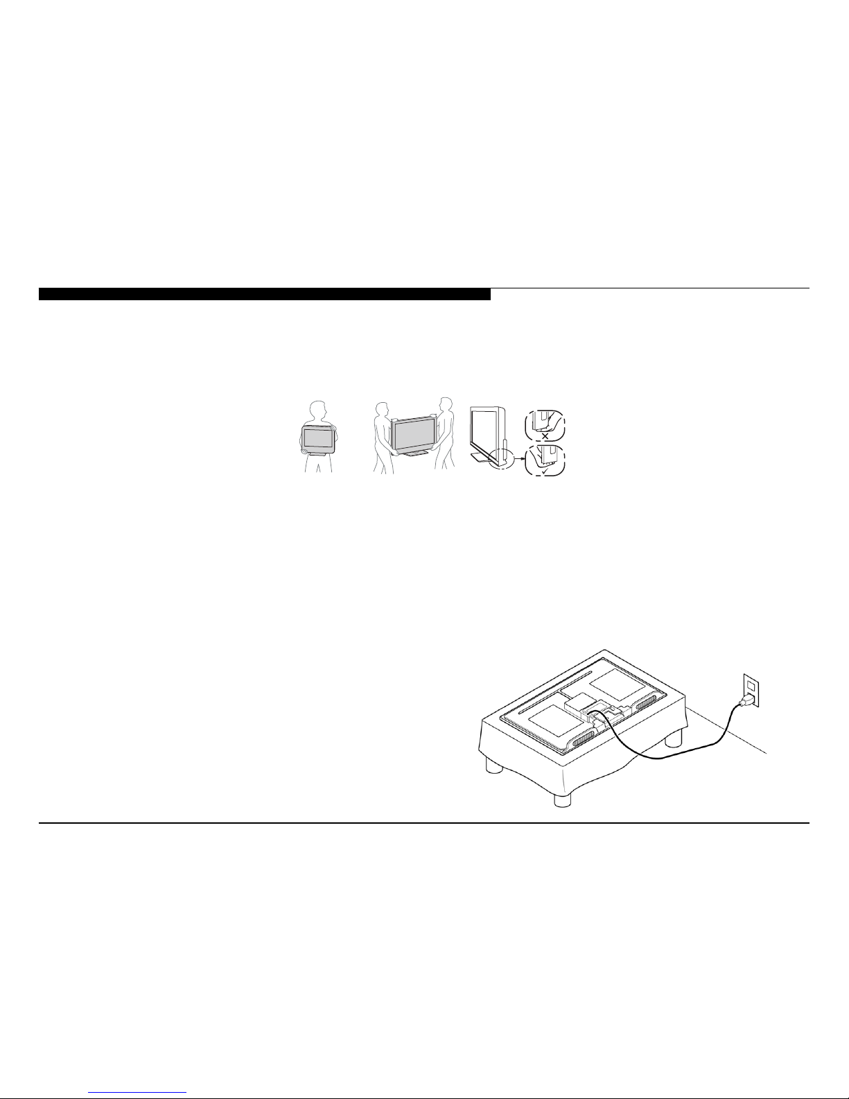
SETTING UP AND CARRYING THE TV
● Disconnect all cables when carrying the TV.
● Carry the TV with the adequate number of people; larger size TVs require two or more people.
● Correct hand placement while carrying the TV is very important for safety and to avoid damage.
ALL EXCEPT 22” MODELS
A
LL 22” MODELS
USE CAUTION WHEN HANDLING THE LCD PANEL
When repairing the LCD panel, be sure you are grounded by using a wrist band.
When installing the LCD panel on a wall, the LCD panel must be secured using the 4 mounting holes on the rear cover.
1. Do not press on the panel or frame edge to avoid the risk of electric shock.
2. Do not scratch or press on the panel with any sharp objects.
3. Do not leave the module in high temperatures or in areas of high humidity for an extended period of time.
4. Do not expose the LCD panel to direct sunlight.
5. Avoid contact with water. It may cause a short circuit within the module.
6. Disconnect the AC power when replacing the backlight or inverter circuit.
(High voltage occurs at the inverter circuit at 650Vrms.)
7. Always clean the LCD panel with a soft cloth material.
8. Use care when handling the wires or connectors of the inverter circuit.
Damaging the wires may cause a short.
9. Protect the panel from ESD to avoid damaging the electronic circuit
(C-MOS).
10. During the repair, DO NOT leave the Power On for more than 1 hour
while the TV is face down on a cloth.

KDL-22EX357/32EX357/32EX358/40EX457/40EX458 iv
CAUTIONS AND WARNINGS
CLEANING THE LCD PANEL
CAUTION: When cleaning the TV, be sure to unplug the power cord to avoid any chance of electric shock.
Clean the cabinet of the TV with a dry soft cloth.
Wipe the LCD screen gently with a soft cloth.
; Stubborn stains may be removed with a cloth slightly moistened with a solution of mild soap and warm water.
; If using a chemically pretreated cloth, please follow the instruction provided on the package.
; Never use strong solvents such as a thinner, alcohol or benzine for cleaning.
; Periodic vacuuming of the ventilation openings is recommended to ensure proper ventilation.
; Do Not use paper towels, any type of abrasive pad, rags, rubber or vinyl materials to clean the screen. Using these materials could easily scratch the
screen which may result in permanent damage.
; Do Not use any cleaning product containing alkaline/acid cleaner, scouring powder, or volatile solvent, such as alcohol, ammonia, benzine, thinner or
insecticide. Using any of these harsh cleaners may result in permanent damage to the screen.
; Do Not spray water or detergent directly onto the TV screen. If liquid drips into the bottom of the screen it may cause a failure.
KDL-22EX357/32EX357/32EX358/40EX457/40EX458 v
CAUTIONS AND WARNINGS
SAFETY CHECK-OUT
After correcting the original service problem, perform the following safety
checks before releasing the set to the customer:
1. Check the area of your repair for unsoldered or poorly soldered
connections. Check the entire board surface for solder splashes
and bridges.
2. Check the interboard wiring to ensure that no wires are pinched or
touching high-wattage resistors.
3. Check that all control knobs, shields, covers, ground straps, and
mounting hardware have been replaced. Be absolutely certain that
you have replaced all the insulators.
4. Look for unauthorized replacement parts, particularly transistors,
that were installed during a previous repair. Point them out to the
customer and recommend their replacement.
5. Look for parts which, though functioning, show obvious signs of
deterioration. Point them out to the customer and recommend their
replacement.
6. Check the line cords for cracks and abrasion. Recommend the
replacement of any such line cord to the customer.
7. Check the antenna terminals, metal trim, metallized knobs, screws,
and all other exposed metal parts for AC leakage. Check leakage
as described in “Leakage Test”.
LEAKAGE TEST
The AC leakage from any exposed metal part to earth ground and from all
exposed metal parts to any exposed metal part having a return to chassis,
must not exceed 0.5 mA (500 microamperes). Leakage current can be
measured by any one of three methods.
1. A commercial leakage tester.
Follow the manufacturers’ instructions provided with the tester.
2. A battery-operated AC milliammeter.
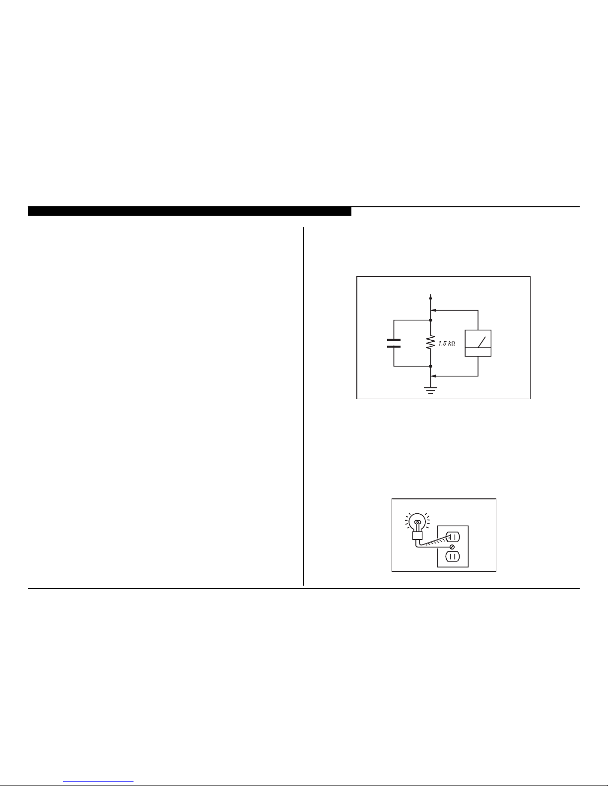
3. Measuring the voltage drop across a resistor by means of a VOM
or battery-operated AC voltmeter. The limit indication is 0.75 V, so
analog meters must have an accurate low voltage scale. Nearly all
battery-operated digital multimeters that have a 2 VAC range are
suitable. (see Figure A)
To Exposed Metal
Parts on Set
0.15 µF
Earth Ground
AC
Voltmete
r
(0.75V)
Figure A. Use an AC voltmeter to check AC leakage.
HOW TO FIND A GOOD EARTH GROUND
The cover-plate retaining screw on most AC outlet boxes is at earth ground.
Verify the AC outlet box retaining screw ground by connecting a 60W to
100W incandescent (not a neon or uorescent lamp) between the hot side of
the receptacle and the retaining screw. Try both slots, if necessary, to locate
the hot side on the line; the lamp should light at normal brilliance if the screw
is at ground potential. (see Figure B)
Figure B. Checking for earth ground.
Trouble Light
AC Outlet Box
KDL-22EX357/32EX357/32EX358/40EX457/40EX458 1
FEATURES
The AZ3FK chassis is one of several designs for the 2012 model line of
Sony Bravia® LCD televisions. This manual covers the following models:
KDL-22EX357
KDL-32EX357
KDL-32EX358
KDL-40EX457
KDL-40EX458
The BRAVIA® Sync™ EX35x and EX45x series LED LCD HDTV
● Brilliant Full HD (1080p) picture quality
● Four HD inputs for a cable box, PS3™ and more1
● Share your pictures on the big screen via USB input
● Crisp detail & contrast w/ Clear Resolution Enhancer
● Optimized picture based on what you’re watching
● Less grain & a clear picture w/ Digital Noise Reduction
● Theater-like movie viewing with 24p True Cinema
● One remote for multiple devices with BRAVIA® Sync™2
SECTION 1 - FEATURES AND OVERVIEW
SPECIFICATIONS
Sistema
Sistema de TV Analógico: NTSC
Digital: DVB-T
Cobertura de canales VHF: 2-13
UHF: 14-69
CATV (Analógico): 1-135
Sistema del panelPanel LCD (pantalla de cristal líquido) Iluminación LED de fondo
Salida de bocinasKDL-40EX458/40EX457: 8 W + 8 W
KDL-32EX358/32EX357: 8 W + 8 W
KDL-22EX357: 5 W + 5 W
Tomas de entrada/salida
CABLE/ANTENNA Terminal externo de 75 ohm para entrada de señal de ra diofrecuencia
VIDEO IN 1/2VIDEO: 1 Vp-p, 75 ohm no equilibrado, sincronización negativa
AUDIO: 500 mVrms (Típico) / Impedancia: 47 kiloohmios
COMPONENT IN YP
BPR
(video componente): Y: 1,0 Vp-p, 75 ohm no equilibrado, sincronización negativa /
P
B
: 0,7 Vp-p, 75 ohm / PR: 0,7 Vp-p, 75 ohm
Formato de señal: 480i, 480p, 720p, 1080i, 1080p
AUDIO: 500 mVrms (Típico) / Impedancia: 47 kiloohmios
HDMI: Video: 480i, 480p, 720p, 1080i, 1080p, 1080/24p
Audio: PCM lineal de dos canales 32; 44,1 y 48 kHz; 16; 20 y 24 bits, Dolby Digital
Entrada de PC
AUDIO OUT Salida de audio, Auriculares (miniconector)
DIGITAL AUDIO OUT
(OPTICAL)
Salida de audio óptica digital (PCM/Dolby Digital)
avitisop ,mho 57 ,p-pV 7,0 ,ocigólana BGR ,sotcatnoc 51 ed D arutainimbuS
Consulte la tabla de referencia de la señal de entrada de la PC para PC y HDMI IN
PC/HDMI IN 1 AUDIO IN Minitoma estéreo, 500 mVrms, (Típico) /
Impedancia: 47 kiloohmios
oediv y acisúm ,otoF :753XE22/753XE23/754XE04-LDKUSB
KDL-40EX458/32EX358: Foto y video
HDMI IN 1/2
PC IN
1. Cables sold separately.
2. Syncs with BRAVIA® Sync or Theatre Sync™ products.
KDL-22EX357/32EX357/32EX358/40EX457/40EX458 2
SECTION 1 - FEATURES AND OVERVIEW
• La disponibilidad de los accesorios opcionales dependerá de las existencias.
•El diseño y las especicaciones están sujetos a cambios sin previo aviso.
* Las dimensiones y la masa son valores aproximados.
Nombre de modelo KDL-40EX458
KDL-40EX457
KDL-32EX358
KDL-32EX357
KDL-22EX357
Corriente y otras especicaciones
Requisitos de alimentación 110-240 V CA, 50/60 Hz
Consumo energético
W 43W 97W 401
en uso
en espera Menos de 0,2 W con 120 V CA y con 240 V CA menos de 0,3 W
Tamaño de pantalla*
(medido diagonalmente)
(cm)
40
101,6
31,5
(32 clase)
80,0
21,6
(22 clase)
54,8
Resolución del monitor 1920 puntos (horizontales) ×
1080 líneas (verticales)
1366 puntos (horizontales) × 768 líneas (verticales)
Bocina/Gama completa (2)
(mm)
001 × 53001 × 04
Dimensiones*con soporte (mm) 941 × 617 × 233753 × 509 × 213 534 × 376 × 147
sin soporte (mm) 941 × 577 × 72 753 × 471 × 71 534 × 348 × 64
patrón de los oricios de
montaje mural (mm)
300 × 300200 × 100100 × 100
tamaño de tornillos de
montaje mural (mm)
M6 (8~12 mm) M4 (6,5~10 mm)
7,48,79,11 )gk( etropos noc*oseP
4,42,71,11 )gk( etropos nis
Accesorios suministradosControl remoto RM-YD081 (1) / Pilas tipo AA (2) / Manual de instrucciones (1 ) / Guía de
cong
uración rápida (1) / Manual de seguridad (1) / Licencia del software (1 ) / Guía de
ensamble de la base de soporte (1) / Soporte de sobremesa (1 juego) / Tornillos (3)
Accesorios opcionales Cables de conexión / Kit de correa de soporte / Soporte de montaje mural: SU-WL500
(solo KDL-40EX458/40EX457) / SU-WL100 (solo KDL-32EX35 8/32EX357/22EX357)
KDL-22EX357/32EX357/32EX358/40EX457/40EX458 3
SECTION 1 - FEATURES AND OVERVIEW
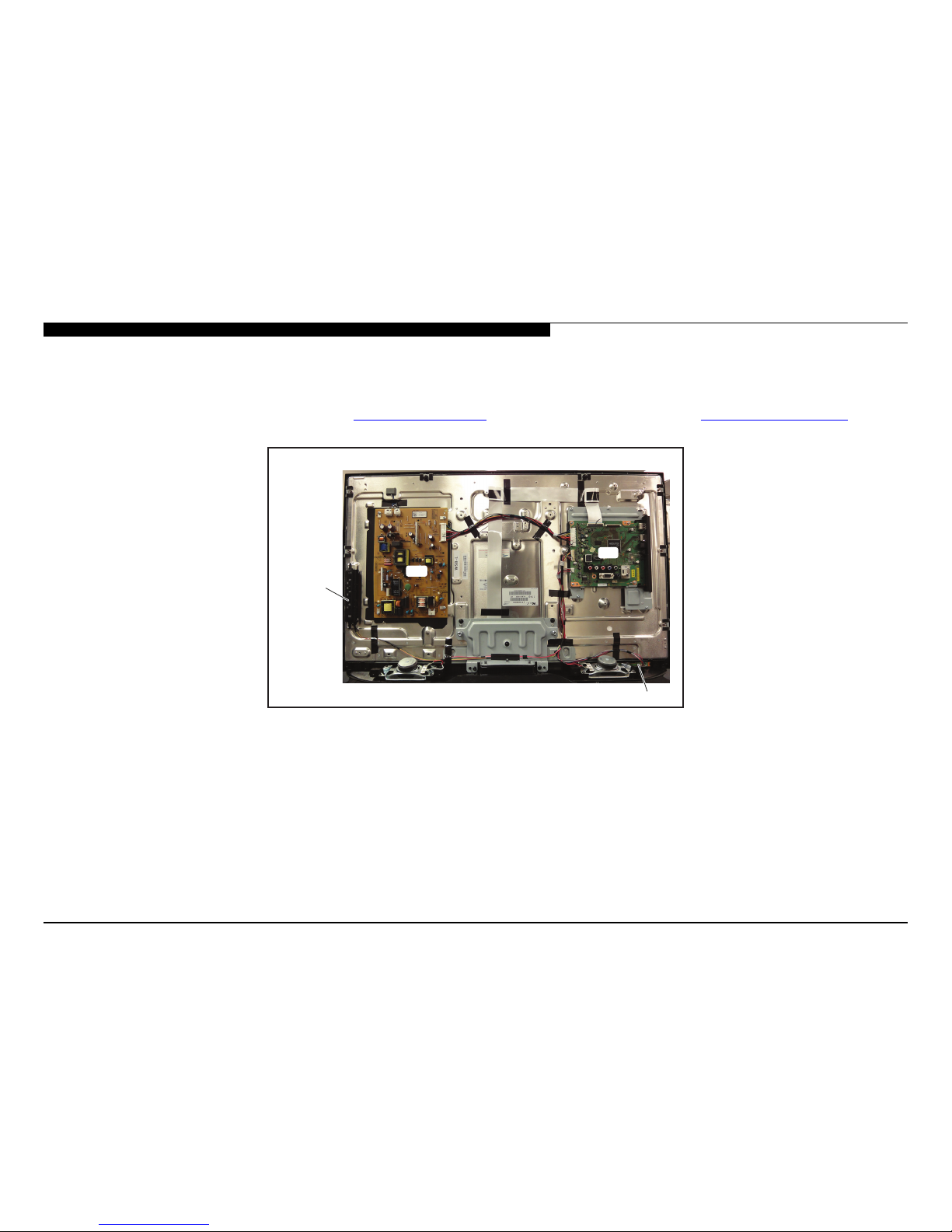
CHASSIS OVERVIEW
The primary circuits in the AZ3FK chassis consist of a Main Board (A Board), Power Supply Board (GE22 Board for the 22” models, GL8 Board for the 32”
models, and GL5 Board for the 40” models), the IR Board (H Board), the Switch Unit, and the LCD Panel Assembly which includes the TCON Board.
NOTE: For connector part number information, refer to “Connectors” on page 21. For Wire Dressing information, refer to “Wire Dressing” on page 23.
SWITCH
UNIT
H
G
A
BOARD LAYOUT FOR ALL MODELS
KDL-22EX357/32EX357/32EX358/40EX457/40EX458 4
SECTION 1 - FEATURES AND OVERVIEW
CPU: The CPU internal to the MT5367 processor controls all aspects of
the television functions. Input from the user along with monitoring of critical
circuits is also performed by this CPU.
LVDS Transmitter: Integrated into the MT5367 is a Low Voltage Differential
Signaling (LVDS) transmitter. This circuit converts the 8-bit parallel RGB
video information into a set of high speed serial lines for noise-free
transmission to the TCON circuits located internally to the LCD panel.
POWER SUPPLY BOARD
There are 3 different Power Supply boards used in the models in this
manual. The type of board depends on the size of LCD panel. They are:
● GE22 for the 22” models
● GL8 for the 32” models
● GL5 for the 40” models
There are 2 distinct sections on the power supply:
Standby Supply: Continuously operational as long as AC power is applied,
the standby supply generates 3.3VDC for the circuits requiring power while
the unit is turned off. An unregulated 15-volt line is present to provide power
to the main relay, PFC and main power supply at turn-on.
Main Supply: Once the power supply receives a power-on command from
the CPU on the A board, the main switching supply is turned on to provide
a regulated 12V source, a dedicated un-regulated 15V for the audio circuits
and an unregulated 24V source for the inverter circuit.
IR BOARD
Designated as the H Board, the IR Board contains the power, standby, and
timer LED’s that is located on this board along with the IR remote receiver
and light level sensor.
SWITCH UNIT
This board contains the power, channel and volume up/down, and menu
buttons.
OVERALL CIRCUIT DESCRIPTION
The “Block Diagram” on page 9 provides an overview of the AZ3FK
chassis. The following are descriptions of the boards and their functions.
MAIN BOARD
Common to all models utilizing the AZ3FK chassis, the Main Board (A
Board) contains most of the video processing circuitry along with all audio
processing. Control of the television is accomplished via a CPU embedded
within the MT5367 processor. Below is a list of the key components located
on the Main Board.
TUNER
The tuner is a combination ATSC/NTSC unit. It can receive traditional
analog NTSC signals via cable or terrestrial along with ATSC digital signals
via terrestrial (8VSB) or cable (64 or 256 QAM).
MT5367 PROCESSOR
This IC performs the majority of the necessary audio and video processing
on the Main Board.
Analog Video Input Switch: All analog video sources are selected and
A/D converted and scaled (if necessary) to 1920 X 1080p 60HZ resolution.
Digital Audio and Video Decoder: The MPEG2 and Digital Dolby audio
streams are received from the tuner for decompression. All video sources
which are not native 1920 X 1080p 60HZ are scaled to this resolution.
Digital audio content is output to the class D amplier for processing and
amplication.
Audio Processing: Analog audio sources are selected and A/D converted
directly by the MT5367. The audio information is then processed digitally.
Digital audio from the tuner and HDMI sources is also input and processed.
Class D amplier provides the drive for the speakers.
HDMI Input and Switching: The customer can select the HDMI1 through
HDMI4 input. Each HDMI input contains a dedicated EDI NVM (not shown)
to provide display information data to any device connected via the HDMI
inputs.

KDL-22EX357/32EX357/32EX358/40EX457/40EX458 5
SECTION 1 - FEATURES AND OVERVIEW
LCD PANEL ASSEMBLY
The LCD Panel Assembly includes the LCD Panel, TCON Board, and LED
Backlight system.
The LCD Panel contains the actual liquid crystals, color lters, and
polarizers. The liquid crystals are manipulated by the applied voltage to
pass a specic amount of light - from the backlight - depending on the level
of voltage applied.
The TCON performs all the control, timing, charge, and discharge functions
driving the operation of the LCD Panel.
A new LCD Panel Assembly from parts will include the following items.
● LCD Panel
● TCON Board
● LED Backlight system.
TCON BOARD
The TCON Board communicates between the LCD Panel and the
microprocessor on the Main Board.
NOTE: The TCON Board is not available as a replacement part for all
models. To determine if the TCON Board is available as a replacement
part, refer to the LCD Panels Manual.
KDL-22EX357/32EX357/32EX358/40EX457/40EX458 6
OVERVIEW
This chapter provides information regarding the Self Diagnosis feature in
our TVs.
UPDATING THE SOFTWARE
The Self Diagnosis function is designed to provide information regarding
the problem with the TV, however, there are several issues that may be
resolved by updating the TV software to the latest version. Most symptoms
that are correctable by software updates involve communications issues
with other devices or minor glitches in the operation of a specic function.
Below is a list of some of the symptoms that may be corrected with a
software update:
● Fluctuations in picture brightness
● Intermittent picture freezing or noise
● Problems with certain inputs (especially HDMI)
● Intermittent or distorted audio
● Erratic remote control operation
● TV turns on and off by itself
● Loss of color
● Internet connectivity
● Certain features not working correctly
(photo or video le viewing)
SECTION 2 - TROUBLESHOOTING
Self Diagnosis
Supported model
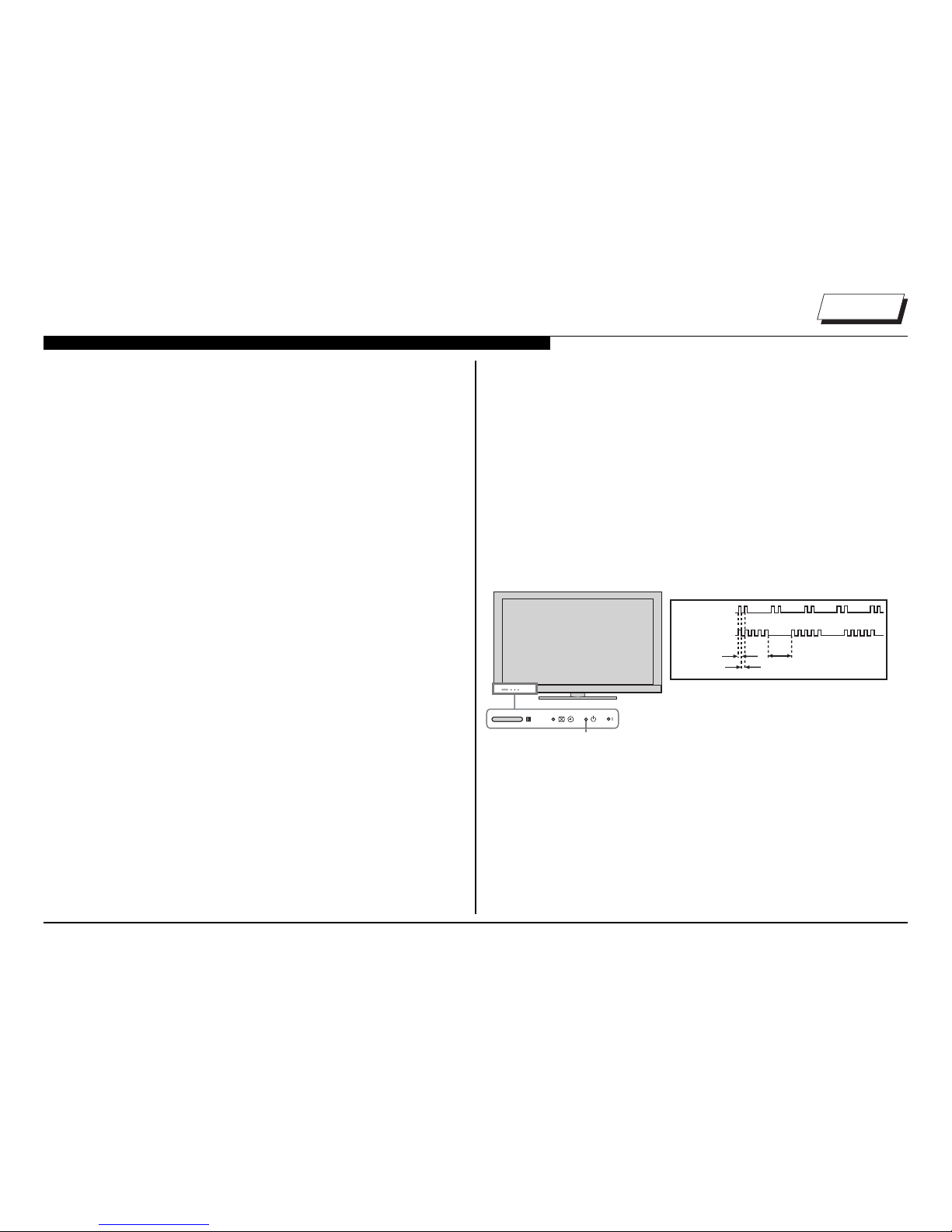
SELF DIAGNOSIS FUNCTION
Critical voltages and circuit operations are monitored by the CPU on the
Main Board. If an error is detected the Self Diagnosis function in the TV will
force the TV to shut down by the CPU. The monitored circuit in which the
fault occurred will automatically cause the CPU to blink the Standby LED
in groups of repeating sequences. The number of times the Standby LED
blinks indicates the possible cause of the problem.
Not all of the available protect codes are used in every model. For example,
models that don’t have the local dimming feature do not use the 4X blink
error as this circuit is found in models that are backlit with uorescent lamps.
The information in this section provides guidance in locating the possible
component causing the shutdown.
STANDBY LED BLINK COUNT
Standby LED
2 times
5 times
LED ON 0.3 sec.
LED OFF 0.3 sec.
LED OFF
3 sec.
LED DISPLAY & BLINK COUNT
 Loading...