

Sony KDL32EX308, KDL22EX308 User Manual
Training Manual
KDL32EX308
AZ1L Direct-View LCD Television Chassis
Circuit Description and Troubleshooting Guide
MODELS: KDL22EX308
KDL32EX308
Course : CTV-68

Table of Contents
Chapter 1 – Introduction ..................................................... 1
Overview .......................................................................... 1
Features .......................................................................... 1
720p Panel ........................................................................... 1
CCFL Backlighting ............................................................... 1
BRAVIA™ Internet Video ..................................................... 1
Enhanced Cross Media Bar (XMB) ...................................... 1
USB2.0 Side Input ............................................................... 2
HDMI 1.3 .............................................................................. 2
Consumer Electronics Control (CEC) ..................................... 2
xvYCC ..................................................................................... 2
Deep Color .............................................................................. 2
Bravia® Sync ....................................................................... 2
Advanced Contrast Enhancer (ACE) ................................... 2
Interactive Program Guide (IPG) ......................................... 2
Digital Living Network Alliance (DLNA) ................................ 2
RGB Ambient Sensor ........................................................... 2
Chapter 2 – Overall Circuit Descriptions ........................... 3
Overview .......................................................................... 3
Overall Circuit Description ............................................... 3
BAL Board ........................................................................... 3
A/V Decoder IC9000 ............................................................... 3
Audio Processing .................................................................... 3
HDMI Switch ........................................................................... 3
CPU ........................................................................................ 3
LVDS Transmitter .................................................................... 3
Power Supply ....................................................................... 4
KDL22EX308 .......................................................................... 4
KDL32EX308 .......................................................................... 4
Inverter ................................................................................. 4
Switch Unit ........................................................................... 4
HLR Board ........................................................................... 4
Chapter 3 – Troubleshooting .............................................. 7
Introduction ...................................................................... 7
Software Updates ............................................................ 7
Software Update Responsibility ........................................... 8
Examples of Software Correctable Symptoms .................... 8
Checking the Software Version ............................................ 8
Special Software Instructions for BAL Board or LCD Panel
Replacement ............................................................... 9
No Video ............................................................................ 10
Audio Troubleshooting ................................................... 14
Power Supply Troubleshooting ...................................... 14
Completely Dead Set ............................................................ 14
Won’t Power On .................................................................... 14
Backlight Issues ............................................................. 18
No Backlight, No Shutdown ............................................... 18
Diagnostics History ........................................................ 18
Circuit Board and Connector Locations ......................... 19
Chapter 4 – Appendix ........................................................ 24
TCON Troubleshooting .................................................. 24
CTV-63 i

Table of Contents (Continued)
Introduction .................................................................... 24
LCD Panel Basics .............................................................. 24
Gate Drivers ....................................................................... 27
Source Drivers ................................................................... 27
Diagnosing a Failed TCON ............................................ 27
TCON Failures ................................................................... 29
Troubleshooting a “DEAD” TCON ......................................... 29
Examples of Actual TCON Failures ................................... 31
LCD Panel Failures ............................................................ 33
CTV-63 ii

Chapter 1 – Introduction
Overview
The AZ1L chassis is one of several designs for the 2010 model line of Sony
Bravia® LCD televisions. Several models will be released incorporating
this chassis. This training manual will cover the EX308 series consisting
of the following models:
KDL22EX308
KDL32EX308
The chassis design revolves around the video processing circuits located
on the BAL board. The key difference between models is determined by
the size of the LCD panel and its manufacturing source. This manual will
describe the new circuit features and individually describe the models
based on these differences.
Features
Several new features are introduced in the EX-M chassis model lineup
along with some carryovers from the previous year.
720p Panel
The EX308 models incorporate a native 1366 X 768 (WXGA) resolution
panel. All video signals exit the video process circuits as 720p 60HZ. The
RGB resolution is 8-bit to provide 256 levels of gray scale.
CCFL Backlighting
Many of the 2010 Sony television models are introducing edge-lit LED
backlighting. The EX308 series incorporates traditional cold-cathode
fluorescent lamps (CCFL) to generate the necessary backlighting for the
LCD panel. A self contained (direct) inverter circuit supplies the necessary
high voltage to drive the backlight lamps.
Wireless Internet Ready
An optional wireless network adapter is available to connect the television
to a home network. These models have an Ethernet port on the rear for
direct connection to the home network. Plugging the optional wireless
network adapter into the USB2.0 port on the side of the television allows
for wireless connectivity when conditions do not allow direct connections.
The wireless adapter supports up to 802.11N.
BRAVIA™ Internet Video
Once available as an optional device to connect to the television, this
feature is now an integral part of the product. The rear of the television
contains an Ethernet port to connect to a high speed network. Access to
online music and video through partnered websites is possible.
Personalized “widgets” are small applications that can be placed on the
screen and accessed with the touch of a button to bring up programming
such as weather, stocks and sports information.
Enhanced Cross Media Bar (XMB)
A new graphics user interface with rich 3-D graphics allowing the user to
customize the setup of the television and to access various adjustments
and control optional devices. Optional external devices can also be
detected and displayed. One example would be when a USB storage
device is plugged into the USB2.0 side input that contains JPEG format
photos. The detection of the device will appear in the XMB graphics icons
along with thumbnail views of the photos stored on the device. The photos
can be viewed individually or be displayed as a slide show.
CTV-68 1

Chapter 1 - Introdcution
USB2.0 Side Input
This feature was available in selected 2008 models and allowed the
viewing of JPEG formatted pictures and playback of MP3 audio files. The
media content has been expanded this year to allow playback of MPEG1
and MPEG2 format video content. An optional wireless network adapter
can be inserted to connect to a wireless home network.
HDMI 1.3
This new version of HDMI introduces several new enhancements and
features and the EX-1 chassis supports 3 of the new features.
Consumer Electronics Control (CEC)
A standardized protocol for the control of consumer electronics devices
allows for communication and control via the HDMI cable on products that
have this feature. Any brand of electronic equipment that is CEC compliant
can communicate with another to generate operational commands. The
Bravia Sync feature uses the CEC format to control other Sony devices
in the system.
xvYCC
The previous color bandwidth limitations applied for compatibility with
analog signals are no longer present with digital signals. This allows for
1.8 times more colors.
Deep Color
Bravia® Sync
By utilizing the CEC feature of HDMI 1.3, this feature allows the customer
to easily control the various Sony devices within their home entertainment
system provided that all of the other devices have this feature included.
Advanced Contrast Enhancer (ACE)
By monitoring the overall level of the video signal, the backlights are
dynamically controlled and reduced during low light level scenes to
enhance the contrast ratio.
Interactive Program Guide (IPG)
An interactive guide is included to provide continuously updated program
information at no charge to the customer. The guide (provided by TV
Guide) is part of the XMB graphics feature. Program material is updated
from the local PBS station when the television is off.
Digital Living Network Alliance (DLNA)
An industry standard networking protocol has been developed by leading
manufacturers to allow other devices such as a compatible computer
to communicate with the television via an Ethernet connection to your
home network. This gives the ability to view photos, audio and movie
content directly from your computer via the network. Future plans include
the ability to download software updates for the television via the home
network.
The previous HDMI specifications limited the RGB sample level to 24-bit.
Deep Color expands this up to 48-bit giving the ability to generate a color
depth of 2.8 trillion levels.
RGB Ambient Sensor
A sensor located on the lower left portion of the front bezel monitors ambient
light levels to adjust the brightness and contrast level of the picture. This
new version is also capable of measuring the color temperature of the
ambient light to adjust the white balance of the displayed picture based
on what type of light source is present in the room.
CTV-68 2

Chapter 2 – Overall Circuit Descriptions
Overview
The primary circuits contained in the AZ1L chassis consists of a main
circuit board (designated as the BAL board), power supply (GD1 Or
G2LE) which varies based on the size of the LCD display, and the LCD
panel assembly. The TCON circuit (normally mounted external to the
LCD panel) is contained inside the panel assembly. The remaining small
boards contain switches, sensors and LED’s.
Overall Circuit Description
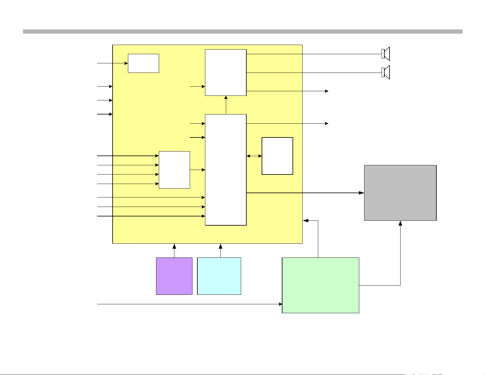
Figure 2-1 illustrates an overall block diagram of the KDL22EX308.
Figure 2-2 illustrates an overall block diagram for the KDL32EX308. Both
chassis designs share most of the same circuits with the power supply
and high voltage circuits to supply the lamp voltages being the significant
difference. Below is a description of the components and their function for
the KDL22EX308.
BAL Board
Common to all models utilizing the AZ1L chassis, the BAL board contains
most of the video processing circuitry along with all audio processing.
Control of the television is accomplished via CPU IC5000. Below is a list
of the key components located on the BAL board.
Digital Audio and Video Decoder: The MPEG2 and Digital Dolby audio
streams are received from the tuner for decompression. All video sources
which are not native 1280 X 720p 60HZ are scaled to this resolution. Digital
audio content is output to IC4200 for processing and amplification.
Audio Processing
IC4200 selects and processes all audio sources. The audio content is
processed digitally, amplified and sent to the speakers.
HDMI Switch
IC2000 functions as a switch for the 4 HDMI inputs. It also serves as
an equalizer to match the low impedance of the input jacks to the high
impedance of the input to IC9000. IC2000 also contains a shared memory
for the EDID information for each HDMI input. When a particular HDMI
input is selected, IC9000 loads the proper EDID information into the
shared memory.
CPU
IC5000 controls most of the operation of the television. All user inputs
are processed here. IC5000 also monitors key voltages and protection
circuits to shut the unit down if a problem is detected.
A/V Decoder IC9000
This IC performs several functions including the following:
Tuner: The tuner is a combination ATSC/NTSC unit. It can receive
traditional analog NTSC signals via cable or terrestrial along with ATSC
digital signals via terrestrial (8VSB) or cable (64 or 256 QAM).
Analog Video Input Switch: The analog video is A/D converted and
scaled (if necessary) to a 1920 X 1080p 60HZ resolution.
LVDS Transmitter
Integrated into IC9000 is a Low Voltage Differential Signaling (LVDS)
transmitter. This circuit converts the 8-bit parallel RGB video information
into a set of high speed serial lines for noise-free transmission to the
TCON board.
CTV-68 3

Chapter 2 - Overall Circuit Description
Power Supply
KDL22EX308
The KDL22EX308 utilizes the GD1 power supply board. There are 3
distinct sections on the power supply:
Standby Supply: Continuously operational as long as AC power is
applied, the standby supply generates 3.3VDC for the circuits requiring
power while the unit is turned off. An unregulated 15-volt line is present to
provide power to the main relay, PFC and main power supply at turn-on.
Main Supply: Once the power supply receives a power-on command
from the CPU on the BAL board, the main switching supply is turned on to
provide a regulated 12V source, along with a dedicated un-regulated 15V
for the audio circuits.
Inverter: The high voltage for the fluorescent backlights is generated by this
circuit. Out-of-phase AC voltage of approximately 1000VRMS is applied
to the balancer circuit. If the inverter circuit fails to start, for whatever
reason, the unit will shut down with a 6-blink error code displayed by the
timer LED.
KDL32EX308
Inverter
The inverter receives the unreg24V from the G2LE board and generates
the required high voltage AC to power the backlight lamps. As of the
writing of this manual, the inverter is not available as a replacement part.
The LCD panel assembly must be replaced.
Switch Unit
This board contains the power, channel and volume up/down and menu
buttons.
HLR Board
The power, standby and timer LED’s are located on this board along
with the IR remote receiver and ambient room light sensor for controlling
backlight and RGB levels.
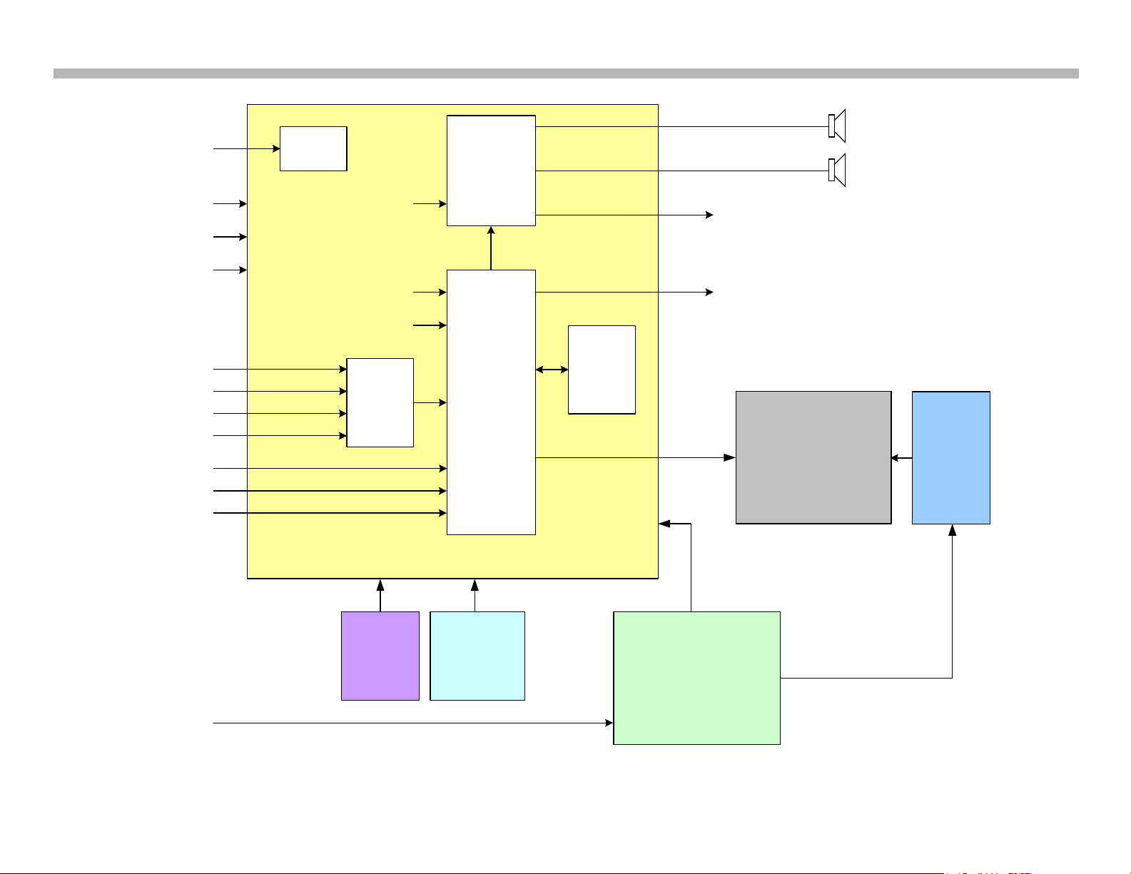
Referring to Figure 2-2 the KDL32EX308 utilizes the G2LE power supply
board. All of the other circuits are the same as the KDL22EX308 except
for the following circuits:
There are 2 distinct sections on the power supply:
Standby Supply: Continuously operational as long as AC power is
applied, the standby supply generates 3.3VDC for the circuits requiring
power while the unit is turned off. An unregulated 15-volt line is present to
provide power to the main relay, PFC and main power supply at turn-on.
Main Supply: Once the power supply receives a power-on command
from the CPU on the BAL board, the main switching supply is turned on
to provide a regulated 12V source, a dedicated un-regulated 15V for the
audio circuits and an unregulated 24V source for the inverter circuit.
CTV-68 4
COMPOSITE OR
COMPONENT
1
RF
COMPOSITE 3
COMPONENT 2
HDMI 1
PC HD15
POWER SUPPLY
INVERTER
SWITCH
UNIT
LED
IR RX
RGB SENSOR
LCD PANEL
BAL
GD1
HLR
L
R
ANALOG AUD IO OUT
OPTICAL AU DIO OUT
HDMI 3
IC4200
AUD IO SW
D/A
AMP
IC9000
A/V
DEC ODER
VIDEO
PROCESS
IC2200
HDMI
SWITCH
EQ
TUNER
ANALOG
VIDEO IN
EITHERNET
USB
2.0
ANALOG
AUD IO IN
HDMI 2
HDMI
4
LVDS
CCFL HV
AC IN
DIGITAL
TUNER IN
DIGITAL
AUD IO
IC5000
SUB
-
MICRO
Chapter 2 - Overall Circuit Description
CTV-68 5
22EX308 OVERALL BLOCK DIAGRAM
FIGURE 2-1
COMPOSITE OR
COMPONENT 1
RF
COMPOSITE 3
COMPONENT 2
HDMI 1
PC HD15
POWER SUPPLY
SWITCH
UNIT
LED
IR RX
RGB SENSOR
LCD PANEL
BAL
G2LE
HLR
L
R
ANALOG AUD IO OUT
OPTICAL AU DIO OUT
HDMI 3
IC4200
AUD IO SW
D/A
AMP
IC9000
A/V
DEC ODER
VIDEO
PROCESS
IC2200
HDMI
SWITCH
EQ
TUNER
ANALOG
VIDEO IN
EITHERNET
USB
2.0
ANALOG
AUD IO IN
HDMI 2
HDMI 4
LVDS
B+/CONTROL
AC IN
DIGITAL
TUNER IN
DIGITAL
AUD IO
IC5000
SUB-
MICRO
INVERTER
Chapter 2 - Overall Circuit Description
CTV-68 6
32EX308 OVERALL BLOCK DIAGRAM
FIGURE 2-2
Chapter 3 – Troubleshooting
Introduction
Most troubleshooting of this chassis focuses on the 3 major components
used:
• The Main Board (BAL)
• Power Supply (G1D or G2LE)
• LCD Panel
This chapter will provide practical troubleshooting procedures based on
the various symptoms that will appear when a particular circuit fails to
operate properly. Typical failure symptoms will be discussed along with
troubleshooting flowcharts for each symptom.
Always remember to log on to the Sony technical support site at http://
www.sony.com/asp to access the latest technical bulletins along with
triage charts to quickly identify the most likely part to complete the repair
based on the symptom.
Software Updates
The subject of software updates is a very important item to point out at
this point. The televisions of today have advanced to the point where they
are not simply a television anymore. They are evolving into devices that
are designed to integrate with numerous other devices found in the home.
Some examples are: Portable audio and video devices, still cameras,
home computer networks and accessing the internet to name a few.
Communications with these varying devices requires that the television be
compatible with varying communications protocols. Although standards
are detailed for each of these protocols, the real world dictates that
occasional errors may occur that could prevent devices from operating or
communicating properly.
Keeping the software in the television up-to-date is a procedure that is
normally handled by the owner of the television. Most customers who own
computers and other digital devices are familiar with and are accustomed
to updating the firmware and software in their products. If a customer
contacts the Sony Customer Support Center and it is deemed to be
correctable with a software update, the issue is handled at the customer
level.
Software updates can be performed in the following ways:
• Manual Downloads: Software updates can be retrieved from the
Sony Support Site at http://esupport.sony.com where they can be
downloaded and placed on a USB thumb drive to be loaded into
the product. The instructions for downloading the software file vary
from chassis to chassis and sometimes from model to model. Read
the instructions included with the software file to properly format
the USB device, unzip the file (if necessary) and the procedure for
loading the software into the television.
• Network Downloads: Internet software updates are becoming
more prevalent as more and more models incorporate home
network capabilities. This method is the most practical since the
television will check for the latest version of software. The models
using the AZ1L chassis provide the customer with a choice of
turning the automatic software update feature on or off. If set to
on, the television will lookup software information while the unit is
in standby. If a newer version is available, it will be downloaded
and installed without any input from the customer
• Built-in Tuner: OTA or cable sources having the proper station that
is transmitting software update data packets. Although the ability
to transmit software update is possible in this way, it is the least
common and is reserved for particular situations where a critical
update is “forced”, thereby updating the unit without any input from
the customer.
CTV-68 7
Chapter 3 - Troubleshooting
INSTALLED
SOFTWARE VERSION
Software Update Responsibility
Software updates are designed to be performed by the customer. Warranty
repairs in which the issue can be resolved by a software update are not
reimbursable. Most issues involving software updates are handled by
the customer service center and should not be directed to an authorized
service center. It is the responsibility of the servicer to prevent service
calls for issues that involve software updates. Exceptions to this are
certain cases whereby the customer is unable or unwilling to perform the
task. In this situation, the servicer will be notified and receive the proper
authorization for reimbursement.
It is the servicer’s responsibility, however, to make certain that any unit
requiring a legitimate service is running the latest software version
and to install it if necessary.
Examples of Software Correctable Symptoms
Always check the Sony Technical Support site for any known and listed
issues that are software related. Most symptoms that are correctable by
software updates involve communications issues with other devices or
minor glitches in the operation of a specific function. Below is a list of
some of the symptoms that may be corrected with a software update:
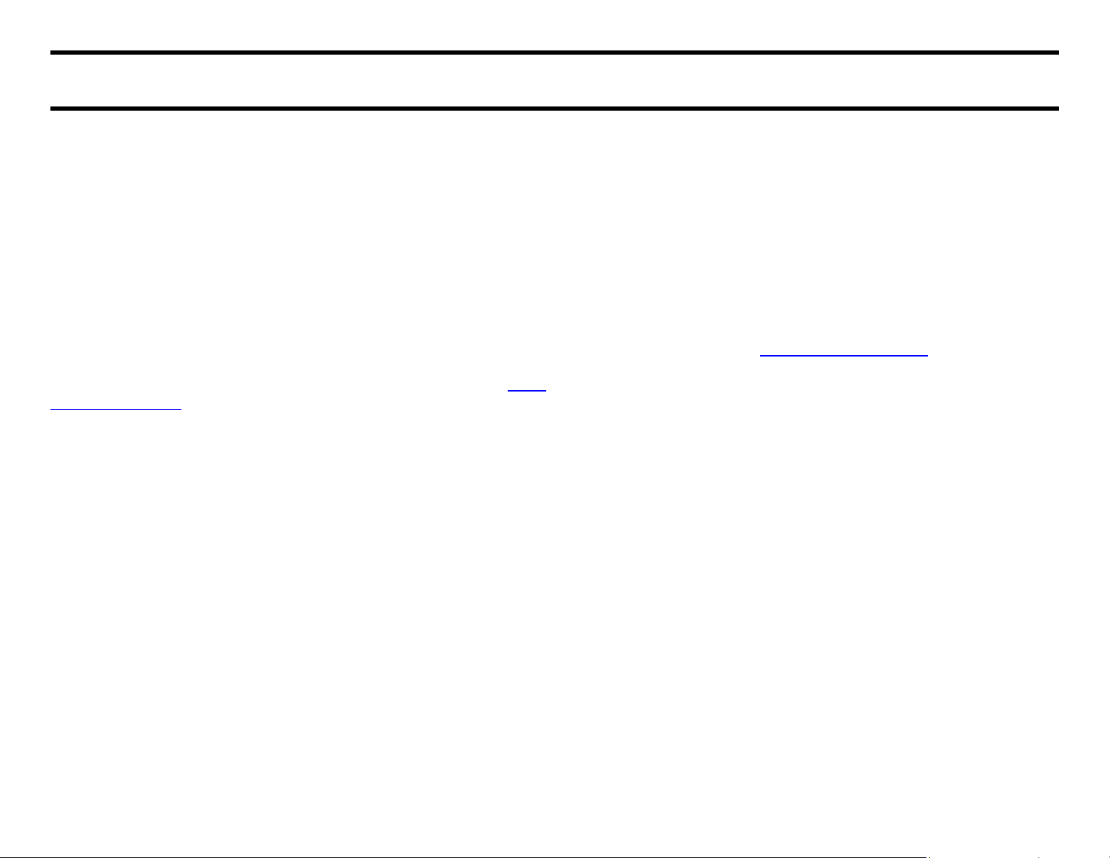
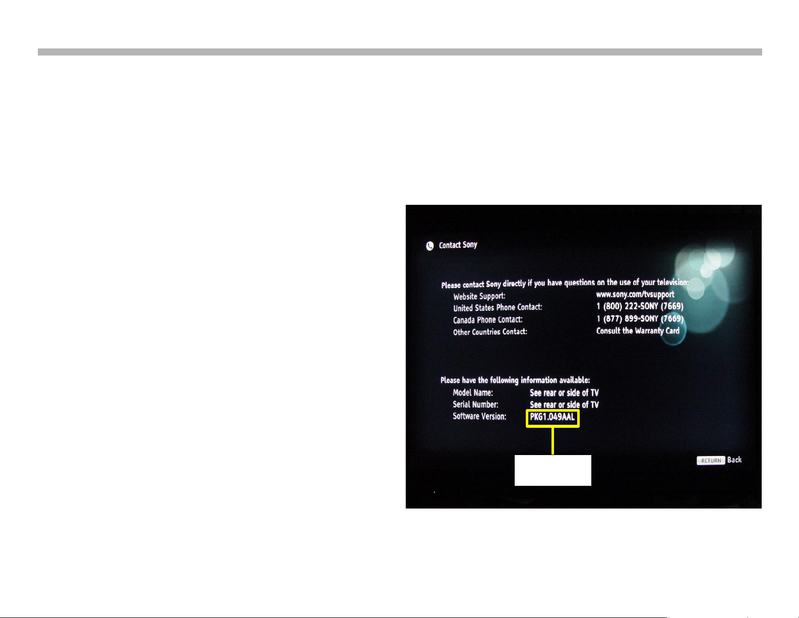
Checking the Software Version
The easiest way to check the version of software is to use the customer
menu. Engage the XMB graphics by pressing “HOME” on the remote
commander. Scroll left on the graphics icons until the end is reached.
Scroll up and select the “Product Support” icon. Select “Contact Sony”.
The information illustrated in Figure 3-1 will appear. Compare the package
version listed on the screen with the version available on line. Install the
software if the on line version is a higher numbered version.
• Fluctuations in picture brightness
• Intermittent picture freezing or noise
• Problems with certain inputs (especially HDMI)
• Intermittent or distorted audio
• Erratic remote control operation
• Unit turns on and off by itself
• Loss of color
• Internet connectivity
• Certain features not working correctly
CTV-68 8
CHECKING THE SOFTWARE VERSION
FIGURE 3-1

Special Software Instructions for BAL Board or LCD Panel Replacement
The 2010 models utilize a “generic” type BAL board. In the past, many
different main boards needed to be stocked due to differences in software
requirements. The software loaded on the board was specific to the
model and its features along with the type of LCD panel installed during
production.
Replacement BAL boards will now be stocked with basic software. Once
the replacement board is installed in the unit, the most current software
is to be installed using a USB storage device containing the necessary
software downloaded from the ASC support web page.
In addition to software installation for specific models, 2 items must be
checked and adjusted in the service mode. The adjustments are Segment
Data (model ID) and Destination (region ID). The procedures for the
software installation are located on the ASC website (http://www.sony.
com/asp). The adjustment procedures are located in the service manual.
This new method of supplying main boards significantly reduces the
complexity of replacing LCD panels and main boards. Information
about the LCD panel is stored on the TCON circuits. This information is
automatically loaded onto the main board when the unit is powered up.
The need to lookup data in the LCD panel manual is no longer necessary.
With the correct software version and proper settings of the Segment and
Destination data the BAL board and/or the TCON or LCD panel can be
replaced more efficiently.
Chapter 3 - Troubleshooting
CTV-68 9
 Loading...