

Sony KDL-22CX520, KDL 32CX520, KDL-32CX523, KDL-40CX520 Service Manual
MODEL
KDL
-
32CX520
KDL
-
46CX520
KDL-22CX520
KDL-32CX523
KDL-40CX520
KDL-40CX523
KDL-46CX523
NO SUFFIX DATE SUPP/CORR DESCRIPTION
SEGMENT.: P-2
PART NO. : 9-888-127-01
1 -01 2011/1 --
1st Issue

SEGMENT
.: P-
2
0
Phillipines, India, Thailand, Malaysia, South Africa
KDL 32CX520
RM GD020,
Hong Kong, SOGUL, Singapore, Indonesia, Vetnam,
RM-CD013
Phillipi
MODEL COMMANDER DEST
KDL-22CX520
KDL-32CX52
KDL-32CX523
KDL-40CX520
KDL-40CX523
RM-GD020 Hong Kong
RM-CD013 Phillipines, India, Thailand, Malaysia, South Africa,
(Taiwan) Australia, New Zealand, Taiwan, Iran, Pakistan
RM-GD020 SOGUL, Saudi Arabia, Nigeria
RM-GD020, Hong Kong, SOGUL, Singapore, Vetnam,
(Taiwan) Australia, New Zealand, Taiwan, Pakistan
RM-GD020 SOGUL, Saudi Arabia, Nigeria
nes, India, Thailand, Malaysia, South Africa,
MODEL COMMANDER DEST
KDL-46CX520
KDL-46CX523
RM-GD020 SOGUL, Singapore, Indonesia, Vetnam,
,
Iran,Pakistan
RM-GD020 SOGUL, Saudi Arabia, Nigeria
TABLE OF CONTENTS
g
y
g
.
Secti
Titl
P
g
g
g
)
g
4-5. Change data by S
(Digital S
)
37
g
g
pping
.
2. SELF DIAGNOSTIC FUNCTION
play Sp
y
y
g
4-12. Ind
42
g
(
(
g
y
g
g
g
g
5-2-1. KDL-22CX520
.
46
g
.
.
.
3-2-4.4 Times Blinking
12
g
g
g
g
g
5-4. Circuit Board Location
52
.
.
3-3.P
Blinking
.
16
.
.
6-1. KDL-22CX520
.
53
.
.
.
.
y
g
6-6-3. KDL-40CX520, 40CX523
.
62
Section Title Page
on
KDL- 22, 32, 40, 46 CX520
RM-GD020, CD013
KDL-32, 40, 46 CX523
RM-GD020
e
age
1. SAFETY NOTES
1-1. Caution Handlin
1-2. Safet
1-3. Le aka
Check Out ......................................……………........................3
e Test ......................................................................................3
of LCD Panel ...........……………............................. 3
1-4. How to Find a Good Earth Ground………………………………………
1-5. Wa rning and Caution .......................................................................... 4
1-6. Lead Free Information ........................................................................ 4
1-7. Ha ndlin
the FLEXIBLE FLAT CABLE (FFC) 5
1-8. How to release Cover AC ................................................................... 6
2-1. Overview of Control Buttons ............................................................... 7
2-2. L ED Dis
2-3. L ED Displa
ecification ...................................................................7
Control ........................................................................... 7
2-4. LED Pattern ........................................................................................ 7
2-5. Sta ndb
2-6. Tria
Led Error Display .................................................................. 8
e Chart ........................................................................................9
3. TROUBLE SHOOTING
3-1. Power Problem ................................................................................... 10
3-2. Standb
3-2-1. 2 Times Blinkin
3-2-2. 3 Times Blinkin
3-2-3. 4 Times Blinkin
LED Blinkin
........................................…………………................. 10
........................................…………………................. 11
........................................…………………................. 12
.......................................…………………..................
3-2-5. 5 Times Blinking........................................…………………................. 13
3-2-6. 6 Times Blinkin
3-2-7. 6 Times Blinkin
3-2-8. 7 Times Blinkin
3-2-9. 8 Times Blinkin
3-2-10. 10 Times Blinkin
ower (Green) Led
........................................…………………................. 14
........................................…………………................. 14
........................................…………………................. 15
........................................…………………................. 15
. ........................................…………………............. 16
................................................................
3-4. No Picture............................................................................................17
3-5. No Sound…………………………………………………………………… 19
3-6. TV Commander and Buttons Malfunction............................................ 19
3-7. Network Malfunction............................................................................ 22
3-8. Camera Malfunction............................................................................
3-9. 3D Malfunction....................................................................................
3-10. HDD-Rec Malfunction.......................................................................... 26
3-11. Sk
3-12. Troubleshootin
pe Troubleshooting........................................................................ 27
Reference................................................................. 28
10
24
25
4. SERVICE ADJUSTMENTS
4-1. Ac cessin
4-2. Ac cessin
4-3. Transistion of .each module in Service Mode...................................... 35
4
4-4. Cha n
4-6. White Balance Adjustment...................................................................38
4-7. Restore White Balance........................................................................ 39
4-8. Cha n
4-9. Vi ewin
4-10. Set to Shi
4-11. Remote Commander Function............................................................
5. DIAGRAMS
5-1. Bl ock Dia
5-1-1. B AT-S
5-1-2. B AT-V
5-2. Con nector Dia
5-2-2. K DL-(32", 40", 46").............................................................................. 47
5-3. Wi re Dressin
5-3-1. KDL-22CX520, 22CX523 ...................................................................
5-3-2. KDL-32CX520, 32CX523 ...................................................................
5-3-3. KDL-40CX520, 40CX523…………………………………………...........
5-3-4. KDL-46CX520, 46CX523……………………………. ........................... 51
5-3-1. KDL-22CX520, 22CX523 ....................................................................52
5-3-2. KDL-32CX520, 32CX523 ...................................................................
5-3-3. KDL-40CX520, 40CX523…………………………………………...........
5-3-4. KDL-46CX520, 46CX523……………………………. ........................... 52
6. DISASSEMBLY, EXPLODED VIEWS AND OTHER PARTS
6-2. KDL-32CX520, 32CX523.....................................................................55
6-3. KDL-40CX520, 40CX523....................................................................
6-4. KDL-46CX520, 46CX523....................................................................
6-6. Other Parts .....................................................……………………….... 61
6-6-1. KDL-22CX520, 22CX523 ...................................................................
6-6-2. KDL-32CX520, 32CX523 ...................................................................
6-6-4. KDL-46CX520, 46CX523……………………………. ........................... 62
Self Diagnostic Menu .........................................................34
Service Mode .................................................................... 35
e data by Service Model (Chassis & VPC module
e Emitter Output........................................................................ 39
Vcom Test Pattern................................................................. 40
ex Flow of Service Control..............................................................
22")......................................................................................... 44
32",40",46") ............................................................................ 45
ervice Model
Condition.................................................................... 41
ram .................................................................................... 44
ram……………………………………….. ..................... 46
.....................................................................................
..................................................................................... 48
........................................................................
.....................................................................................
…………………………………………...........
ervice Mode
36
41
48
49
50
52
52
57
59
61
61
OPERATING INSTRUCTION
-2-
SECTION 1
LCD
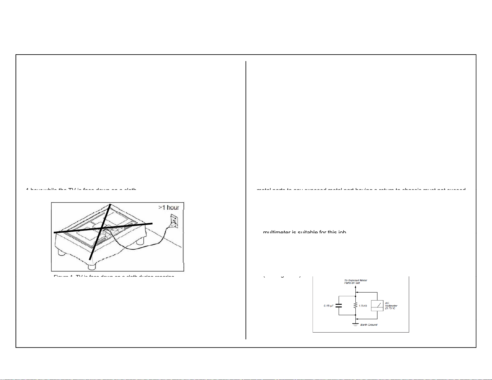
1 hour while
the TV is face down on a cloth
metal parts to any exposed metal part having a return to chassis must not exceed
multimeter
is suitable for this job
(
)
(g)
Figure 1
face down on a cloth during
reparing
SAFETY NOTES
KDL- 22, 32, 40, 46 CX520
RM-GD020, CD013
KDL-32, 40, 46 CX523
RM-GD020
1-1. Caution Handling of LCD Panel
When repairing the LCD Panel, make sure you are grounded with a wrist band.
When repairing the LCD Panel on the wall, the panel must be secured using the 4
mounting holes on the rear cover.
1) Do not press the panel or frame edge to avoid the risk of electric shock.
2) Do not scratch or press on the panel with any sharp objects.
3) Do not leave the module in high temperature or in areas of high humidity for
an extended period of time.
4) Do not expose the LCD panel to direct sunlight.
5) Avoid contact with water. It may cause short circuit within the module.
6) Disconnect the AC power when replacing the backlight (CCFL) or
inverter circuit. (High voltage occurs at the inverter circuit at 650Vrms)
7) Always clean the
8) Use care when handling the wires or connectors of the inverter circuit.
Damaging the wires may cause a short circuit.
9) Protect the panel from ESD to avoid damaging the electronic circuit
(C-MOS).
10) During the repair, DO NOT leave the Power On or Burn-in period for more than
panel with a soft cloth material.
.
. TV is
3)Check all control knobs, shields, covers, ground straps and mounting
hardware have been replaced. Be absolutely certain you have replaced all
the insulators.
4) Look for unauthorized replacement parts, particularly transistors that were
installed during a previous repair. Point them out to the customer and
recommend their replacement.
5) Look for parts which, though functioning show obvious signs of deterioration.
Point them out to the customer and recommend their replacement.
6) Check the line cords for cracks and abrasion. Recommend the replacement
of any such line cord to the customer.
7) Check the antenna terminals, metal trim, metallized knobs, screws and all
other exposed metal parts for AC leakage. Check leakage test as described
next.
8. For safety reasons, repairing the Power board and/or Inverter board is prohibited.
1-3. Leakage Test
The AC leakage from any exposed metal part to earth ground and from all exposed
0.5mA (500 microamperes).
Leakage current can be measured by any one of the three methods:-
1. A commercial leakage tester such as the SIMPSON 229 or RCA WT-540A.
Follow the manufacturers instructions to use those instructions.
2. A battery-operated AC milliampmeter. The DATA PRECISION 245 digital
.
3. Measuring the voltage drop across a resistor by means of a VOM or battery
operated AC voltmeter. The 'limit' indication is 0.75V so analog meters must
have an accurate low voltage scale. The SIMPSON'S 250 and SANWA
SH-63TRD are examples of passive VOMs that are suitable. Nearly all
battery operated digital multimeters that have a 2 VAC range are suitable.
see Figure 1.
1-2. Safety Check-Out
After correcting the original service problem, perform the following safety checks
before releasing the set to the customer:-
1) Check the area of your repair for unsoldered or poorly soldered connections.
Check the entire board surface for solder splashes and bridges.
2) Check the interboard wiring to ensure that no wires are pinched or contact
high-wattage resistors.
Figure 2. AC voltmeter to check AC leakage
-3-
Safety Notes
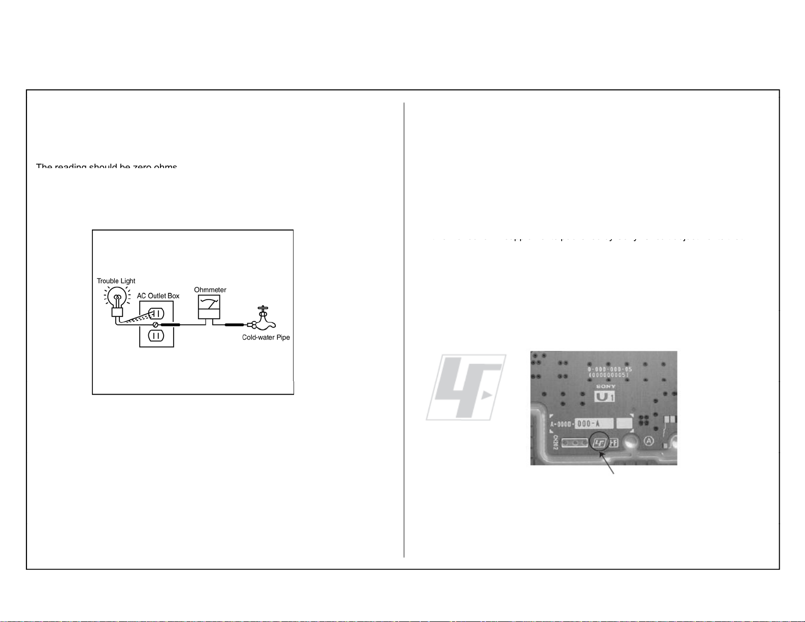
The reading should be zero ohms
this manual or in supplements published by Sony. Circuit adjustments that
1-4. How to Find a Good Earth Ground
A cold-water pipe is a guaranteed earth ground; the cover-plate retaining screw
on most AC outlet boxes is also at earth ground.
If the retaining screw is to be used as your earth ground, verify that it is at ground
by measuring the resistance between it and a cold-water pipe with an ohmmeter.
.
If a cold-water pipe is not accessible, connect a 60- to 100-watt trouble- light (not
a neon lamp) between the hot side of the receptacle and the retaining screw. Try
both slots, if necessary, to locate the hot side on the line; the lamp should light at
normal brilliance if the screw is at ground potential (see Figure B).
KDL- 22, 32, 40, 46 CX520
RM-GD020, CD013
KDL-32, 40, 46 CX523
RM-GD020
c) Be sure to follow these guidelines to protect your property and avoid causing
serious injury.
• Carry the TV with an adequate number of people; larger size TVs require
two or more people.
• Correct hand placement while carrying the TV is very important for safety
and to avoid damages.
d) Components identified by shading and ! mark on the schematic diagrams,
exploded views, and in the parts list are critical for safe operation. Replace
these components with Sony parts whose part numbers appear as shown in
are critical for safe operation are identified in this manual. Follow these
procedures whenever critical components are replaced or improper
operation is suspected.
1-6. Lead Free Information
The circuit boards used in these models have been processed using Lead Free
Solder. The boards are identified by the LF logo located close to the board
designation.
Figure 3. Checking for earth ground.
1-5. Warnings and Caution
a) These servicing instructions are for use by qualified service personnel only.
To reduce the risk of electric shock, do not perform any servicing other than
that contained in the operating instructions unless you are qualified to do so.
b) An isolation transformer should be used during any service to avoid possible
shock hazard, because of live chassis. The chassis of this receiver is directly
connected to the ac power line.
Figure 2: LF
Logo
Figure 3: LF logo on circuit board
-4-
Safety Notes
gg g
KDL- 22, 32, 40, 46 CX520
RM-GD020, CD013
KDL-32, 40, 46 CX523
RM-GD020
The servicing of these boards requires special precautions. It is strongly
recommended to use Lead Free Solder material in order to guarantee optimal
quality of new solder joints. Lead Free Solder is available under the following
part numbers:-
Part Number Diameter Remarks
7-640-005-19 0.3mm 0.25Kg
7-640-005-20 0.4mm 0.50Kg
7-640-005-21 0.5mm 0.50Kg
7-640-005-22 0.6mm 0.25Kg
7-640-005-23 0.8mm 1.00Kg
7-640-005-24 1.0mm 1.00Kg
7-640-005-25 1.2mm 1.00Kg
7-640-005-26 1.6mm 1.00Kg
Due to high melting point of Lead Free Solder, the soldering iron tip
temperature needs to be set to 370 degrees centigrade. This requires
soldering equipment capable of accurate temperature control coupled
with a good heat recovery characteristics.
For more information on the use of Lead Free Solder,
please refer to http://www.sony-training.com
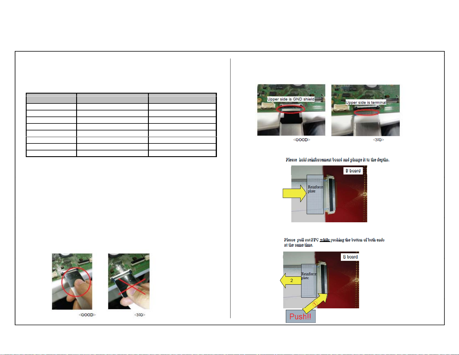
1-7. Handling the FLEXIBLE FLAT CABLE (FFC)
When you insert / pull out FFC, please grasp a reinforcement board
and main body of FFC.
FFC can reverse insertion to connector of B board.
If reverse insertion FFC, all pins short-circuit, and board is broken.
< Insertion>
<Pull out>
-5-
Safety Notes
Note:
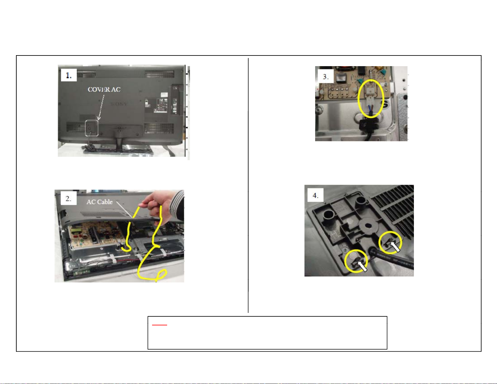
1-8. How to release COVER AC (Service and repair information)
KDL- 22, 32, 40, 46 CX520
RM-GD020, CD013
KDL-32, 40, 46 CX523
RM-GD020
1. Remove screw for Rear Cover and “COVER AC”.
( Refer Section 6 for screw information).
2. Open Rear Cover with “COVER AC” and AC cable are attached.
Make sure to hold cable not to give any tension to connector
and scratch damage for cable.
Take care not to cut your hand when release hook, especially metal Rear Cover.
Confirm if the hook broken before reuse COVER AC.
In case hook broken is occurred, replace with new one.
3. Release AC cable connector.
4. Release hook of “COVER AC” and remove it.
-6-
SECTION 2
g
y
ggy
( by
)
Connecting/Tim
5
Home
Diagnosis mode
p
Blink
p
0.5sec
SELF DIAGNOSTIC FUNCTION
KDL- 22, 32, 40, 46 CX520
RM-GD020, RM-CD013
KDL-32, 40, 46 CX523
RM-GD020
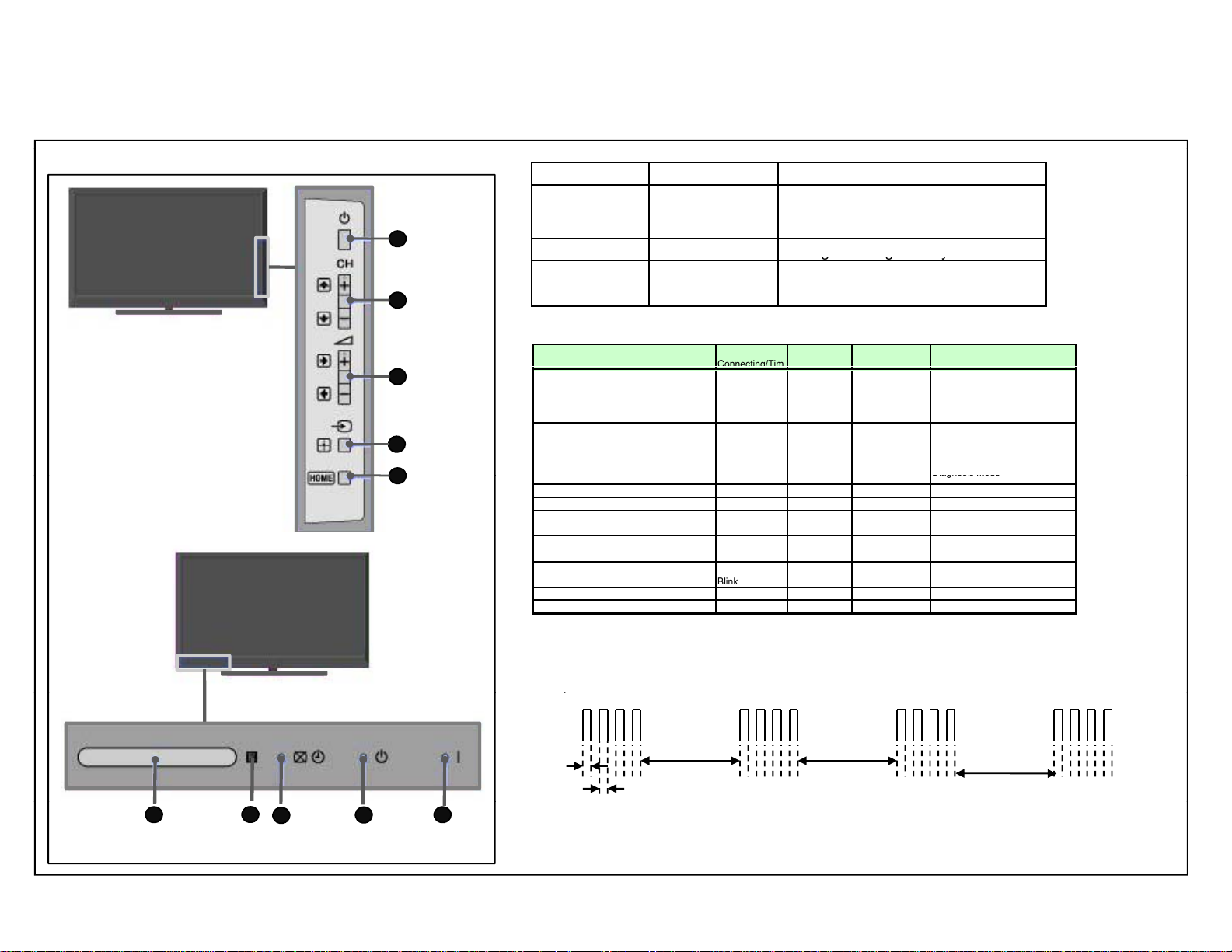
2-1. Overview of Control Buttons
Power
1
Program
2
Volume
3
Input Select/
4
Enter
2-2 LED Display Specification
LED Type Description Remark
Green Lights at Power On
POWER GREEN:LED
RED: LED
STANDBY RED: One LED Red Li
ORANGE/GREEN:
TIMER/PIC OFF
Red Lights when recording ( only
applicable in Japan and Europe models)
hts during standb
Orange Lights during Timer activation
and Green Lights during Picture Off.Two LEDs
2-3. LED Display Control
Picture Off/
Power Off
( by power button or AC off )
Power On Off Off
Standby
remote control off only
Self Diagnosis Off RED Blink Off
Aging mode Off Off
Software Updating
Software Updating finish ORANGE Lit Off GREEN Lit
Test Reset finish ORANGE Lit
Error of panel ID
[REC][Sleep Timer][Power ON]
[Picture Off][On Timer][REC][Power ON] GREEN Off RED
Off Off
Off RED Lit
OffEnd of Aging mode Off
ORANGE
Blink
ORANGE
ORANGE
Standby LED Power /REC
Off
GREEN
Off
GREEN Blink Blinking:0.5sec On / 0.5sec Off
GREEN Blink
RED Lit
Red
Off GREEN Blink
Off
Off
GREEN Lit
RED
Blinking PatternStatus
Refer to Blinking pattern of Self
Blinking:3sec On / 3sec Off
Blinking:5sec On / 1sec Off
Blinking:0.5sec On / 0.5sec Off
6
Remote
Sensor
2-4. LED Pattern
When safety shutdown occurs, Standby LED display reports the cause by using the lightning
atterns as indicated below.
0.5sec
6
6
7
IR Logo
8
Picture
Timer
9
Off/Standby
Indicator
10
Power
Indicator
Example: The figure above shows LED display when SHUTDOWN is caused by Balancer
Error. It repeats flashing for a specified number of times in 0.5sec/cycle and has a 3 seconds
interval of lighting off. Please note that a 3 seconds interval of lighting off is fixed regardless of abnormal state types.
3.0sec 3.0sec
3.0sec
-7-
Self Diagnostic Function
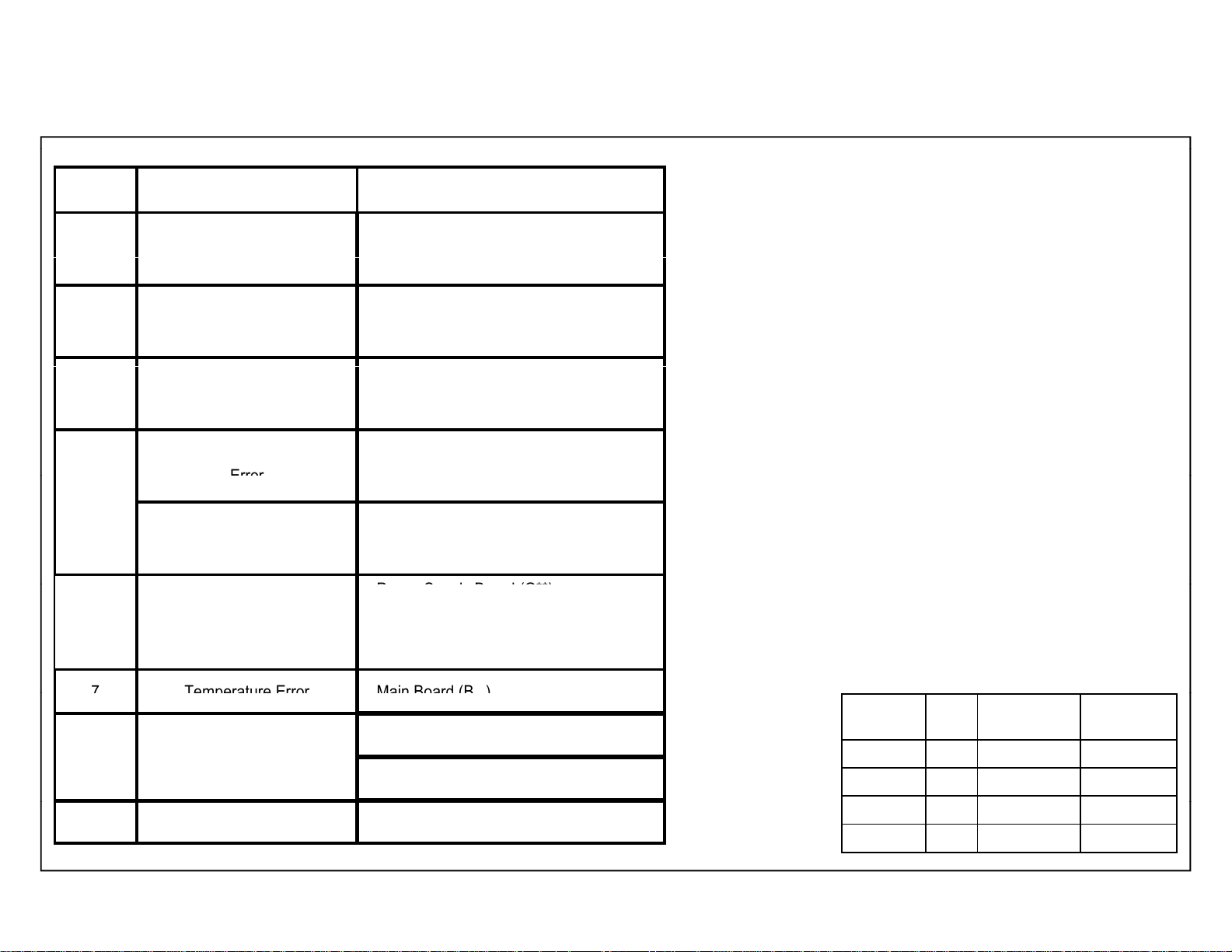
2-5. Standby LED Error Display
Error
P
(G**)
7
Temperature Error
Main Board (B )
KDL- 22, 32, 40, 46 CX520
RM-GD020, RM-CD013
KDL-32, 40, 46 CX523
RM-GD020
.
Blinking
Times
Error
Countermeasure to replaced either/all
2 Main Power Error Power Supply Board (G**)
Main Board (B**)
3
4 Not applicable for this model
Main Board/ DC Alert Error/
Audio Error
Balancer Error/ MM SPI Error/
VLED Error
T Con Error/ HFR Error/ FRC
Main Board (B**)
Not applicable for this model
5
TCon
Panel ID NVM Error
Backlight Error6
Panel Module
ower Supply Board
Main Board (B**)
Panel Module
8 Software Error
10 EmItter Error (3D models) Not applicable for this model
.
**
Main Board (B**)
Wifi (Not applicable for this model)
–8–
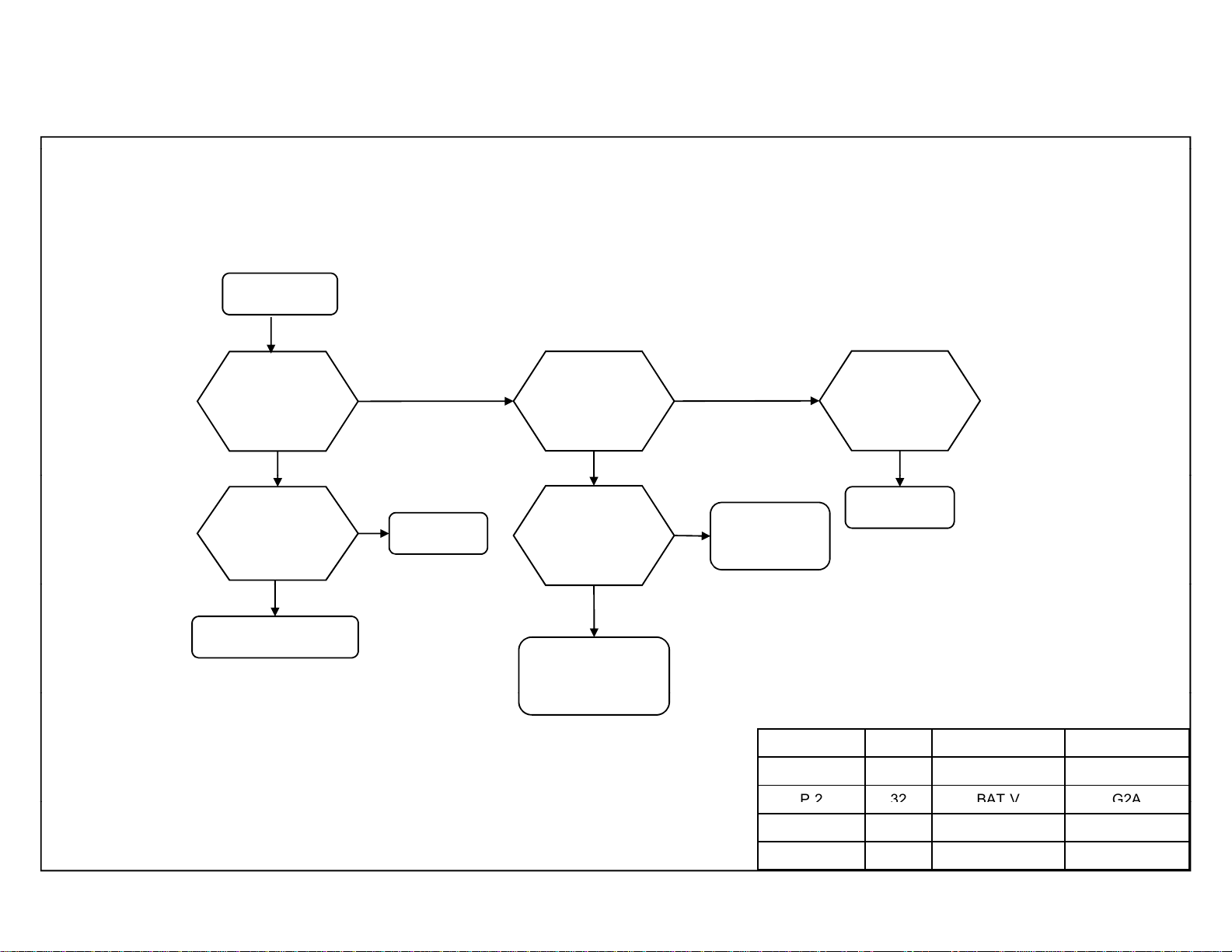
Segment Size B* Board
Type
P-2 22 BAT-S GD1
P-2 32 BAT-V G2A
P-2 40 BAT-V G2B
P-2 46 BAT-V G3
G* Board
Type
Self Diagnostic Function
g
(
)
p
g
()
p
p
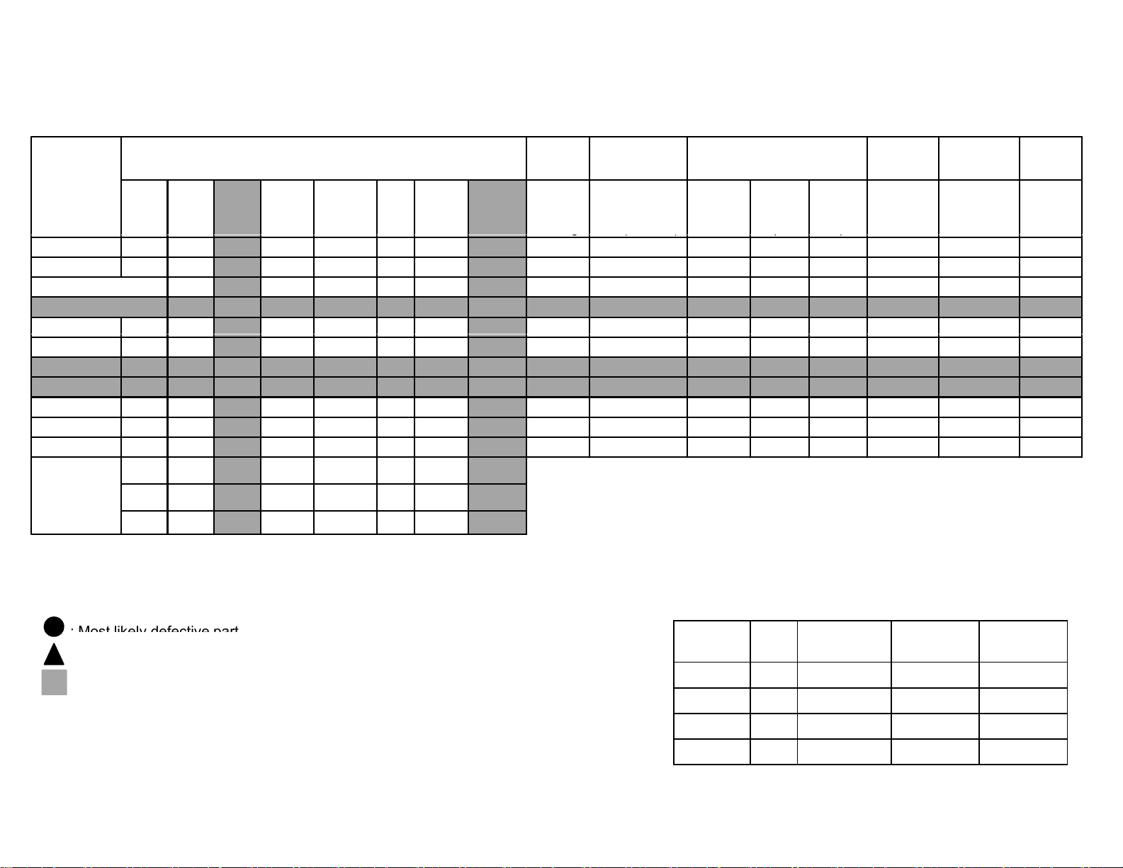
: Most likely defective
part
2-6. Triage Chart
KDL- 22, 32, 40, 46 CX520
RM-GD020, RM-CD013
KDL-32, 40, 46 CX523
RM-GD020
Reference
B* BOARD
G* BOARD
H* BOARD(IR)
RF Module(RF)
SPEAKER
Skype Module
Wifi Module
LD* BOARD
LVDS CABLE
TCON
LCD Panel
Problem
Symptoms - Shutdown. Power LED
blinking red diagnostics sequences
234 5 6 78 10
▲
▲▲ ▲
▲▲ ▲
▲
▲
▲
▲▲ ▲ ▲
POWER POWER POWER
AUDIO
PANEL
(TCON)
▲
PANEL
(Backlight) TEMP Software EMIT-TER
FAN
(N/A)
▲
Green LED
Blinking
Green LED
non-stop
Blinkin
▲▲▲
▲
No
Power Remote Network Audio
Stationary
colored
No Green Power
Dead Set
LED
lines or
dots
Video
- missing or distorted
No video
One of
In
No video
uts
all Inputs No Remote
Wireless
can't connect No Audio
▲▲
▲
: Secondary possible defective part.
: Not Applicable for this model.
.
Segment Size B* Board G* Board H* Board
Segment Size B* Board
Type
G* Board
Type
H* Board
Type
P-2 22 BAT-S GD1 HLR
P-2 32 BAT-V G2A HLR
P-2 40 BAT-V G2B HLR
0 G
P-2 46 BAT-V G3 HLR
LD* Board not use for this model.
–9–

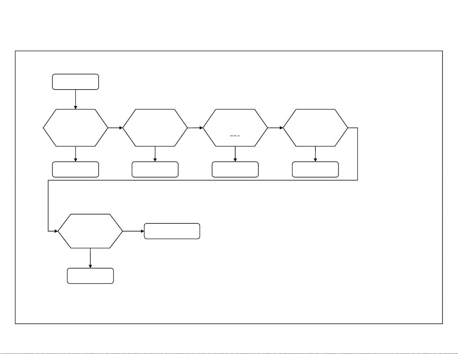
3-1. Power Problem
Turn on the Switch
NG
the B* Board
No Power
SECTION 3
TROUBLESHOOTING
3-2. Standby Led Blinking
3-2-1. 2-times blinking (Main Power Error)
KDL- 22, 32, 40, 46 CX520
RM-GD020, RM-CD013
KDL-32, 40, 46 CX523
RM-GD020
Check
** Power Saving Switch
SW ON
Check STBY 3.3V
at 10 pin of CN6001
on the B* Board
OK
B* Board
SW OFF
Replace the Harness
Between G* Board and
B* Board
Symptom
improvement
Harness
**Power Saving Switch:Only for BAT-L model
Segment Size B* Board Type G* Board Type
NG
G* Board
P-2 22 BAT-S GD1
2-times blinking
Check REG12V
at pins 2/3 of
CN6001 on
12V OK
B* Board
NO 12V
Replace the Harness
Between G* Board and
B* Board
Symptom
improvement
Harness
NG
G* Board
P-2 32 BAT-V G2A
P-2 40 BAT-V G2B
P-2 46 BAT-V G3
-10-
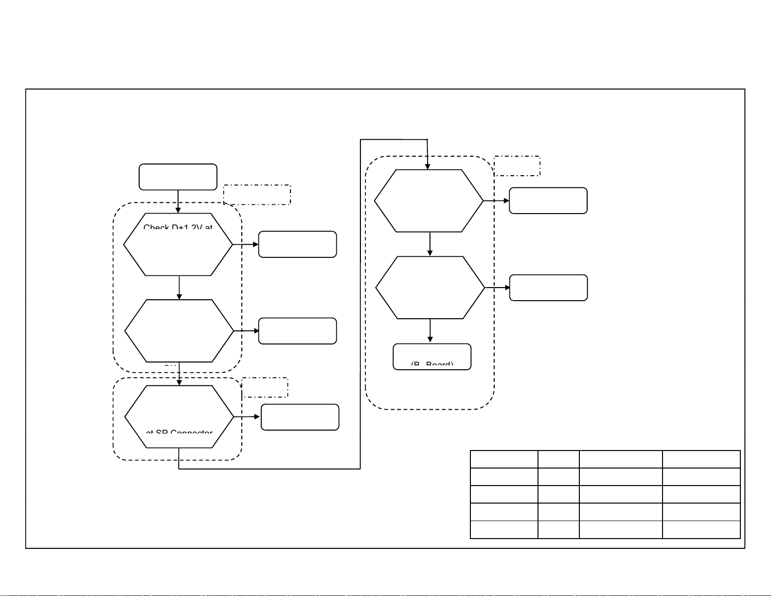
Self Diagnostic Function
A
Check D+1.2V at
(BBoard)
(B Board)
OK
at SP Connector
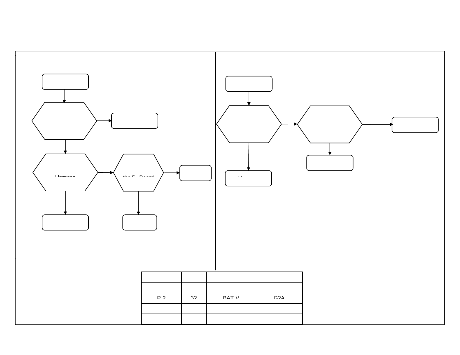
3-2-2. 3-times blinking( DC Alert & Audio Error)
3-times blinking
DC_ALERT
NG
JL6007
on the B* Board
OK
Check +3.3V_MAIN
at JL9234 on
the B* Board
NG
F6001,IC6005,etc
(B*Board)
F6003,IC6003,etc
(B*Board)
CheckAUDIO+12.5V
atpin8/9of
CN6001on
theB*Board
OK
Check +12.5V
at F4601 on
the B* Board
OK
IC4601,etc
*
NG
NG
KDL- 22, 32, 40, 46 CX520
RM-GD020, RM-CD013
KDL-32, 40, 46 CX523
RM-GD020
UDIO
G* Board
F4601,IC4601,etc
*
Check
Speaker Impedance
OK
AUDIO
NG
Speaker
Segment Size B* Board Type G* Board Type
P-2 22 BAT-S GD1
P-2 32 BAT-V G2A
P-2 40 BAT-V G2B
P-2 46 BAT-V G3
-11-
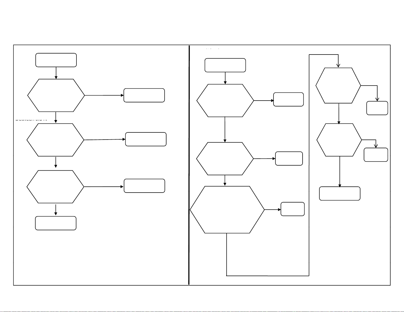
Self Diagnostic Function
F
(
2
b-1
)
Between
Between
0.84
V
Check the h
the LED driver board
3-2-3. 4-times blinking (Balancer Error)
3-2-4. 4-times blinking (Including SPI Error)
KDL- 22, 32, 40, 46 CX520
RM-GD020, RM-CD013
KDL-32, 40, 46 CX523
RM-GD020
4-times blinking
Check
PANEL_FAIL at
JL6017
on the B* Board
to 2.65V
Change G* Board
NG
Change LED Driver Board
Panel
For (3a-1,3a-2,2b-2, 2b-3)
* Not applicable for these model
Below 0.84V
B* Board
Symptom
improvement
Symptom
improvement
G* Board
LED Driver Board
or
0.84V to
2.65V
between the T-con board and
the LED driver board,
between the G board and
* Not applicable for these model
4-times blinking
Check
PANEL_FAIL at
JL6017
on the B* Board
Symptom
improvement
Change G* Board
NG
arness
.
Below
0.84V
NG
B* Board
G* Board
Harness
Change
T-CON Board
NG
Change
LED Driver
Board
Panel
Symptom
improvement
T-con
Board
Symptom
improvement
LEDDriver
Board
-12 -
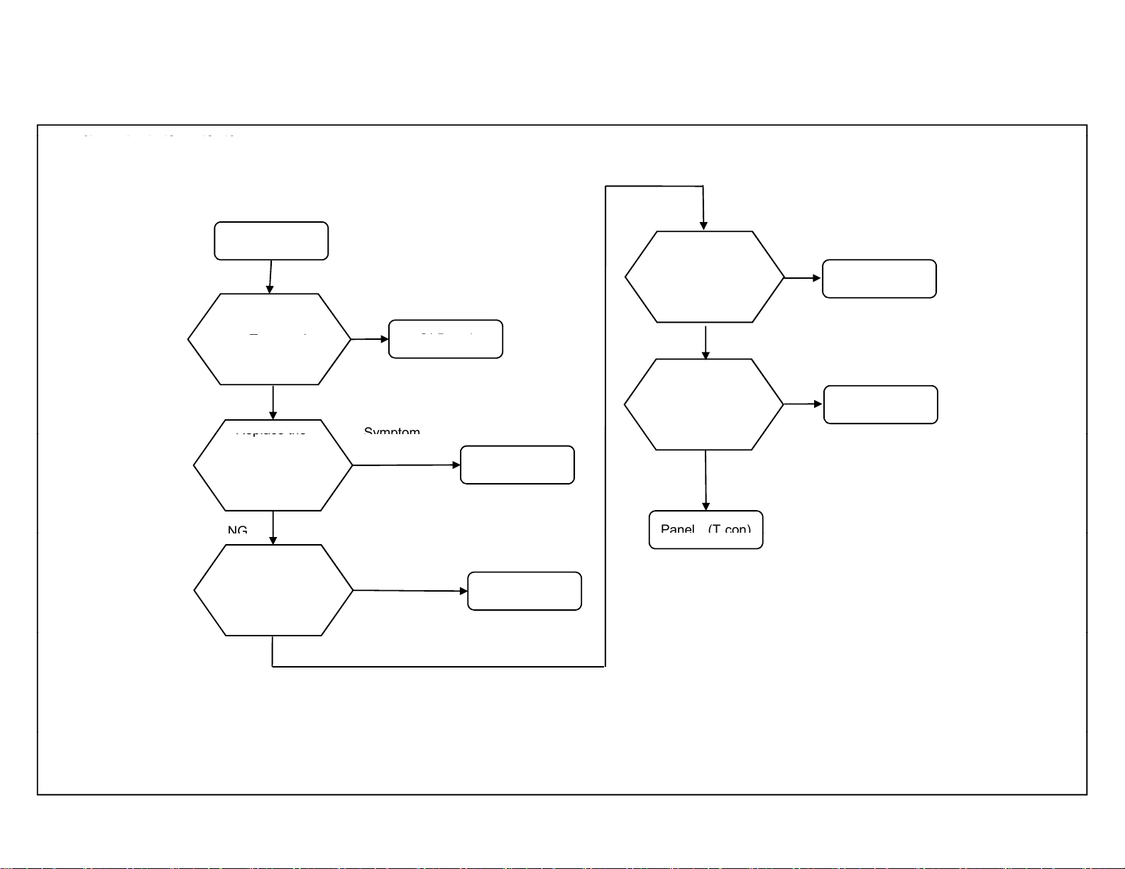
Self Diagnostic Function
F
2)
_
_p
G* B
d
Replace the
Symptom
Panel
(T
con)
NG
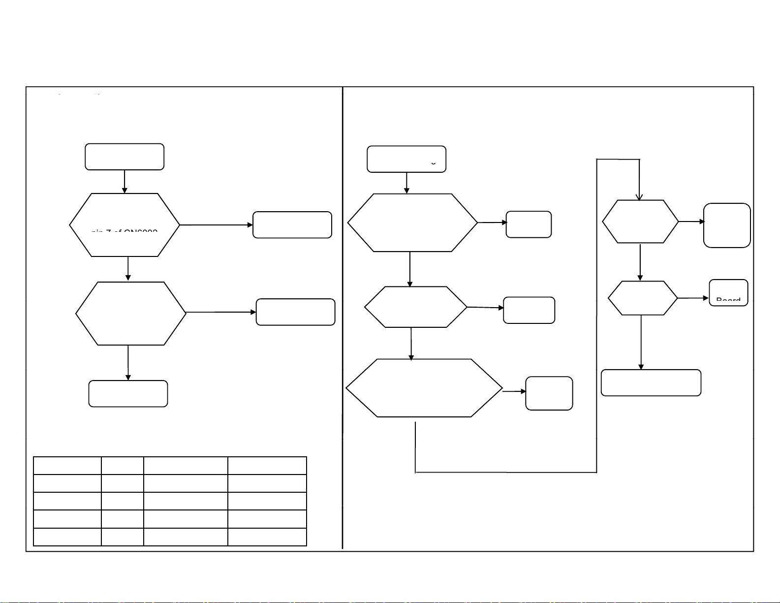
3-2-5. 5-times blinking (T-con Error)
or (3a-1, 3a-2, 2b-1, 2b-
* Not applicable for these model
5-time blinking
KDL- 22, 32, 40, 46 CX520
RM-GD020, RM-CD013
KDL-32, 40, 46 CX523
RM-GD020
Symptom
improvement
Check
PANEL
VCC at pin 1
of CN6001 on
on the B* Board
OK
Harness Between
G* and Panel
(a)
Replace
the LVDS Harness
NG
RGB sensor Change
NG
oar
Panel (T-con)
improvement
Harness
(a) exclude 60Hz Panel Model
Symptom
improvement
LVDS Harness
change
Symptom
improvement
-
(b) Only for (2b-1, 2b-2)
NG
RGB Sensor
B* Board
-13 -
Self Diagnostic Function
g
F
2
)
g
pin 7 of CN6002
theT
conboardandthe
Board
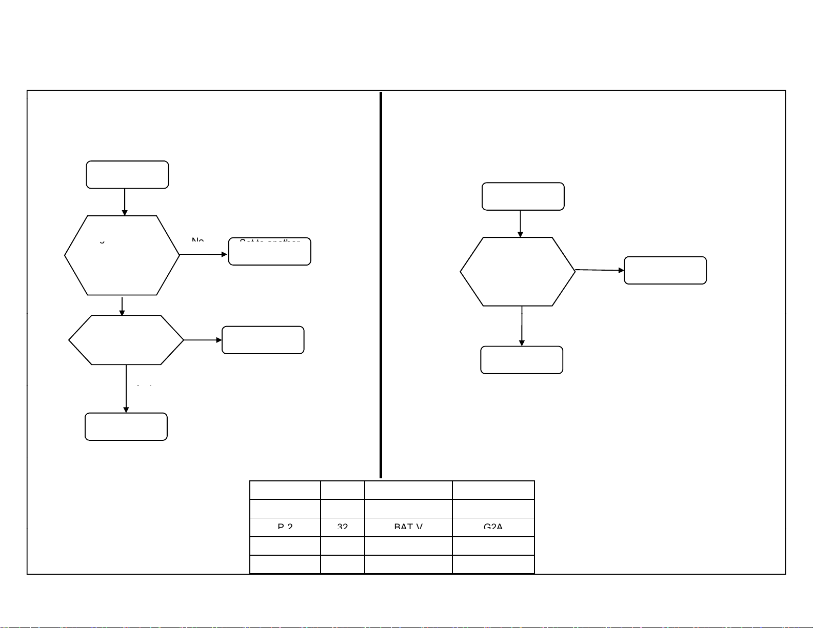
3-2-6. 6-times blinking (Backlight Error)
3-2-7. 6-times blinking (Backlight Error)
KDL- 22, 32, 40, 46 CX520
RM-GD020, RM-CD013
KDL-32, 40, 46 CX523
RM-GD020
or (P-1, P-
6-time blinking
Check
BL_ERR at
on the B* Board
Over 2.65V
Change G* Board
NG
Panel
under 2.65V
Symptom
improvement
B* Board
G* board
For (3a-1, 3a-2, 2b-1, 2b-2)
* Not applicable for these model
6-time blinkin
Check
theharnessbetween
‐
LEDdriverboard.
OK
Change G* board
NG
CheckFFCconnection
betweentheLEDdriverboard
Andthelightsource
(insidethepanelmodule)
NG
Symptom
improvement
Harness
G* Board
NG
Connection
FFC
Symptom
Change
LED driver
board
NG
Change B*
board
Light Source
(Inside Panel Module)
improvement
Symptom
improvement
LED
Driver
Board
B*
Segment Size B* Board Type G* Board Type
P-2 22 BAT-S GD1
P-2 32 BAT-V G2A
P-2 40 BAT-V G2B
P-2 46 BAT-V G3
OK
-14 -
Self Diagnostic Function
g
Set
to another
No
yp
P232
BAT
V G2A
3-2-8. 7-times blinking (Temperature Error)
7-times blinking
Setting Circumstance
Is OK?
Temperature,
Ventilation, etc.
Yes
NG
Change B* Board,
and Aging a few hours
location, etc.
Panel
3-2-9. 8-times blinking (Software Error)
8-times blinking
If the Symptom
Improved by changing
the WIFI module
Symptom
improvement
WIFI Module
NG
KDL- 22, 32, 40, 46 CX520
RM-GD020, RM-CD013
KDL-32, 40, 46 CX523
RM-GD020
B* Board
Symptom
improvement
B* Board
Segment Size B* Board Type G* Board Type
P-2 22 BAT-S GD1
-
P-2 40 BAT-V G2B
P-2 46 BAT-V G3
-
-15 -
Self Diagnostic Function
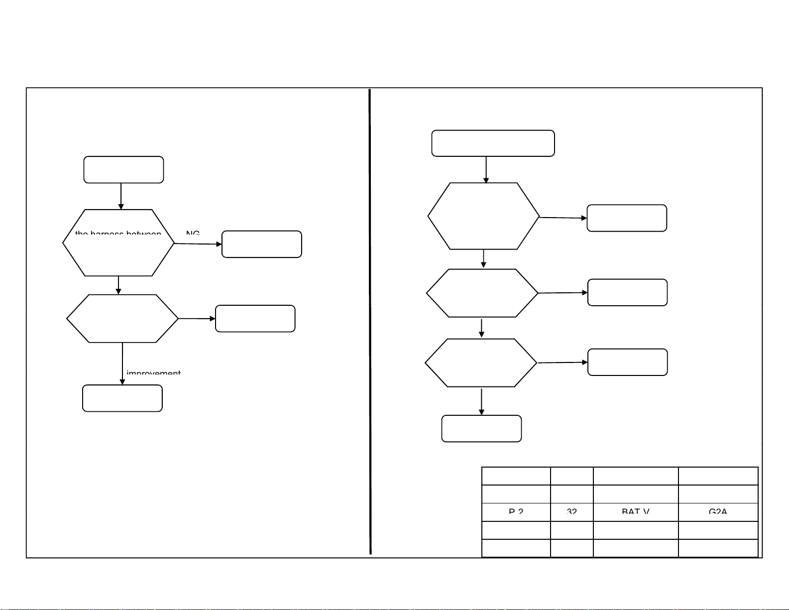
the harness between
NG
improvement
P232
BAT
V G2A
3-2-10. 10-times blinking (Emitter error) (3D) Models only
3-3. POWER(Green) LED BLINKING
3-3-1. Non-Stop blinking
KDL- 22, 32, 40, 46 CX520
RM-GD020, RM-CD013
KDL-32, 40, 46 CX523
RM-GD020
For (3a-1, 3a-2, 2b-1, 2b-2)
* Not applicable for these model
10-time blinking
Check
the T-con board and
the HEM2 board
OK
Change HEM2 Board
Symptom
NG
harness
T-CON board
For (P-1, P-2)
POWER (Green) blinking
Check
the harness between
the G* board and
Panel
OK
Check Panel
OK
Check G* board
NG
NG
NG
harness
Panel
G* Board
HEM2 Board
-16-
B* Board
OK
Segment Size B* Board Type G* Board Type
P-2 22 BAT-S GD1
-
P-2 40 BAT-V G2B
P-2 46 BAT-V G3
-
Self Diagnostic Function
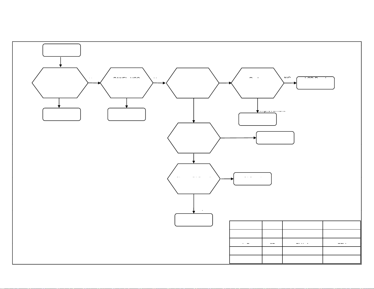
N
Repl
LCD Panel
NG
PANEL_VCC
Y
)
improvement
)
Ch
d)
G* B
d
p
pP232BAT
V G2A
3-4. NO PICTURE
3-4-1. (Except HFR Model)
KDL- 22, 32, 40, 46 CX520
RM-GD020, RM-CD013
KDL-32, 40, 46 CX523
RM-GD020
No Picture
Press HOME Key.
XMB(Menu)
displayed?
Yes
B* Board
about 5V : 22”(WXGA))Model,
about 12V : except 22” ”(WXGA)) Model
Check
o
at JL6004
on the B* Board
No
G* Board
es
BL_ON:L
Check
BL_ON at JL6018
on the B* Board
Replace Harness
(Between G* Board
to B* Board)
NG
ange B* Boar
BL_ON:H
Symptom
improvement
NG
ace
the LVDS Harness
Symptom
Harness
(LVDS)
Harness
(G* to B*
oar
(T-con)
B* Board
-17-
Symptom
im
rovement
Segment Size B* Board Type G* Board Type
P-2 22 BAT-S GD1
-
P-2 40 BAT-V G2B
P-2 46 BAT-V G3
-
Self Diagnostic Function
FFC
3-4. NO PICTURE
3-4-. (HFR Model Only)
* Not applicable for these model
No Picture
KDL- 22, 32, 40, 46 CX520
RM-GD020, RM-CD013
KDL-32, 40, 46 CX523
RM-GD020
Press HOME Key.
OSD displayed?
Yes
B* Board
Change G* Board
Symptom
improvement
G* Board
No
Check the G*- LD*
Harness
NG
NG
(T‐con,LD*)
LCDPanel
OK
the B-Tcon, Tcon-LD*
Symptom
improvement
Replace
B‐Tcon,Tcon‐LD*
FFC
NG
Symptom
improvement
NG
Change B* Board
B* BoardHarness
-18-
Self Diagnostic Function
Harness
the B Board
H
P232
BAT
V G2A
3.5. NO SOUND
KDL- 22, 32, 40, 46 CX520
3.6. TV COMMANDER & BUTTONS MALFUNCTION
3-6-1. TV key Malfunction
RM-GD020, RM-CD013
KDL-32, 40, 46 CX523
RM-GD020
“Speakers setting”
“TV Speakers”
Change the Speaker
Speaker Harness Speaker
No Sound
Check the
improvement
“Audio System”
Change to
“TV Speaker”
NG
Replace
*
NGSymptom
Symptom
improvement
B* Board
Buttonmalfunction
ontheTV
Replace the harness
between B*
to Switch Unit
Symptom
improvement
arness
NG
Switch Unit change
NG
B* Board
Symptom
improvement
Switch Unit
Segment Size B* Board Type G* Board Type
P-2 22 BAT-S GD1
-
P-2 40 BAT-V G2B
P-2 46 BAT-V G3
-
-19-
Self Diagnostic Function
betweentheBBoard
Sensorisbroken
p
Exch
H
p
P232
BAT
V G2A
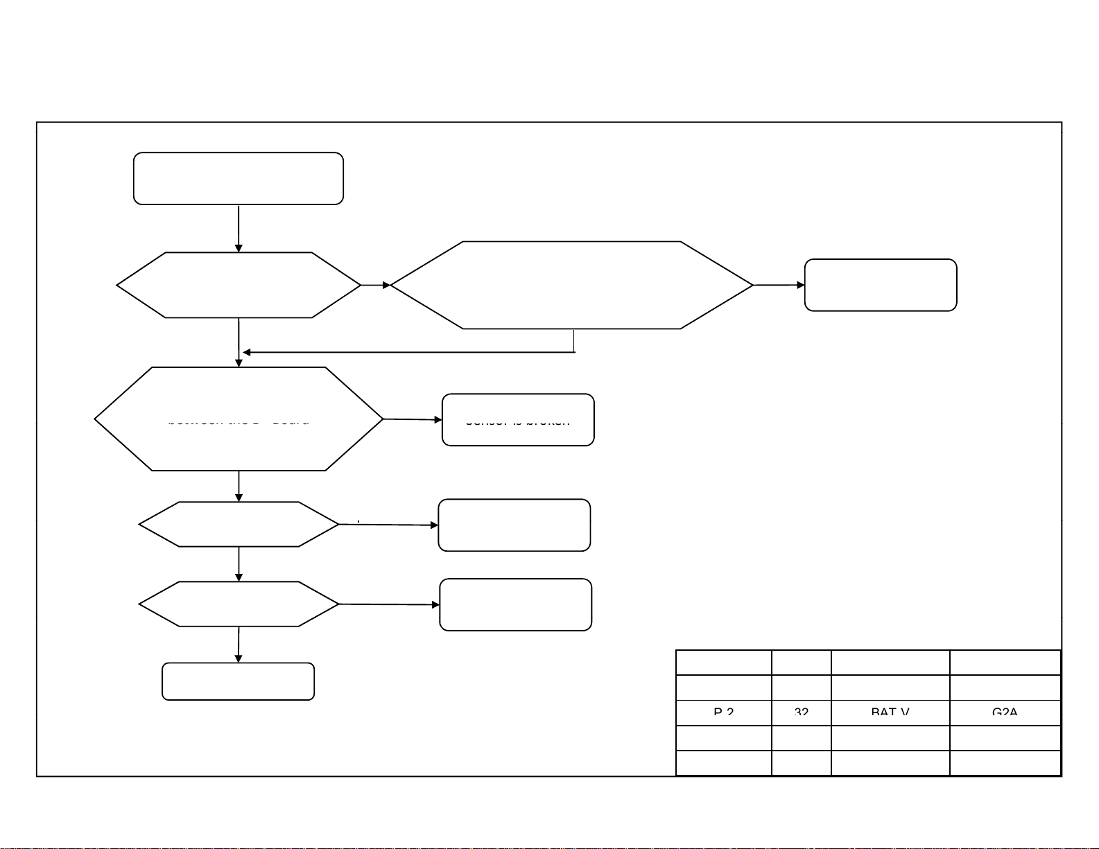
3-6-2. IR remote commander malfunction
TVisn’tcontrolled
byremotecommander
KDL- 22, 32, 40, 46 CX520
RM-GD020, RM-CD013
KDL-32, 40, 46 CX523
RM-GD020
GreenLEDlight
atpowerindicator
NG
ChecktheHarness
*
andtheHLRBoard
NG
angeHarness
NG
ExchangeHLRboard
NG
OK
OK
Symptom
im
rovement
Symptom
improvement
GreenLEDblinksatpower
Indicatorwhenusingcommander
nearsensor’swindow
NG
arness
HLRboard
OK
Mechanical
(ex.bezel)
B*board
-20-
Segment Size B* Board Type G* Board Type
P-2 22 BAT-S GD1
-
P-2 40 BAT-V G2B
P-2 46 BAT-V G3
-
Self Diagnostic Function
Un
registered
Repl
NG
NG
improvement
improvement
3-6-3. RF remote commander malfunction
* Not applicable for these model.
Commander
malfunction
KDL- 22, 32, 40, 46 CX520
RM-GD020, RM-CD013
KDL-32, 40, 46 CX523
RM-GD020
Re‐Pairingaction
Symptomimprovement
RFremotecommanderis
‐
ReplacetheHarness
betweentheB*Board
andtheRFModule
Symptom
NG
Usenewbatteries
Symptomimprovement
Batterieslowpower
theRFModule
RFModuleHarness
ace
Symptom
NG
Symptomimprovement
Usenewremote
andnewbatteries
Remote
Bboard
NG
-21-
Self Diagnostic Function
NG
P232
BAT
V G2A
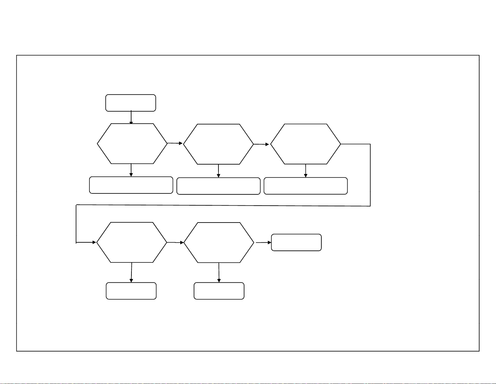
3-7. Network MALFUNCTION
3-7-1. Wired Network malfunction
WiredNetwork
ontheTV
KDL- 22, 32, 40, 46 CX520
RM-GD020, RM-CD013
KDL-32, 40, 46 CX523
RM-GD020
Connectionresult
CableConnection
NG
Checkcable Bboard
NG
EthernetCable
OK
OK
Connectionresult
LocalAccess
WiredSet‐up
IPaddresssetting
Manual
CheckIPaddress
&
Localroutersetting
OK
Auto
Check Localrouter
DHCPserver
Connectionresult
InternetAccess
NG
Proxysetting
Segment Size B* Board Type G* Board Type
P-2 22 BAT-S GD1
-
P-2 40 BAT-V G2B
-
P-2 46 BAT-V G3
-22-
Self Diagnostic Function
3-7-2. Internal Wireless Network malfunction
* Not applicable for these model.
3-7-3. USB Wireless Network malfunction
KDL- 22, 32, 40, 46 CX520
RM-GD020, RM-CD013
KDL-32, 40, 46 CX523
RM-GD020
WirelessNetwork
ontheTV
ErrorMessageappear
whentheWireless
Networkisselected?
Yes
WirelessModule,Harness
No
Istheradiofield
Strengthtooweak
orevenNosignal?
Yes
AccessPoint
No
B*Board
WirelessNetwork
ontheTV
ErrorMessageappear
whentheWireless
Networkisselected?
Yes
USBDongle
No
Istheradiofield
Strengthtooweak
orevenNosignal?
Yes
AccessPoint
No
B*Board
Segment Size B* Board Type G* Board Type
P-2 22 BAT-S GD1
P-2 32 BAT-V G2A
P-2 40 BAT-V G2B
P-2 46 BAT-V G3
-23-
Self Diagnostic Function
E
r
Is image is clear on
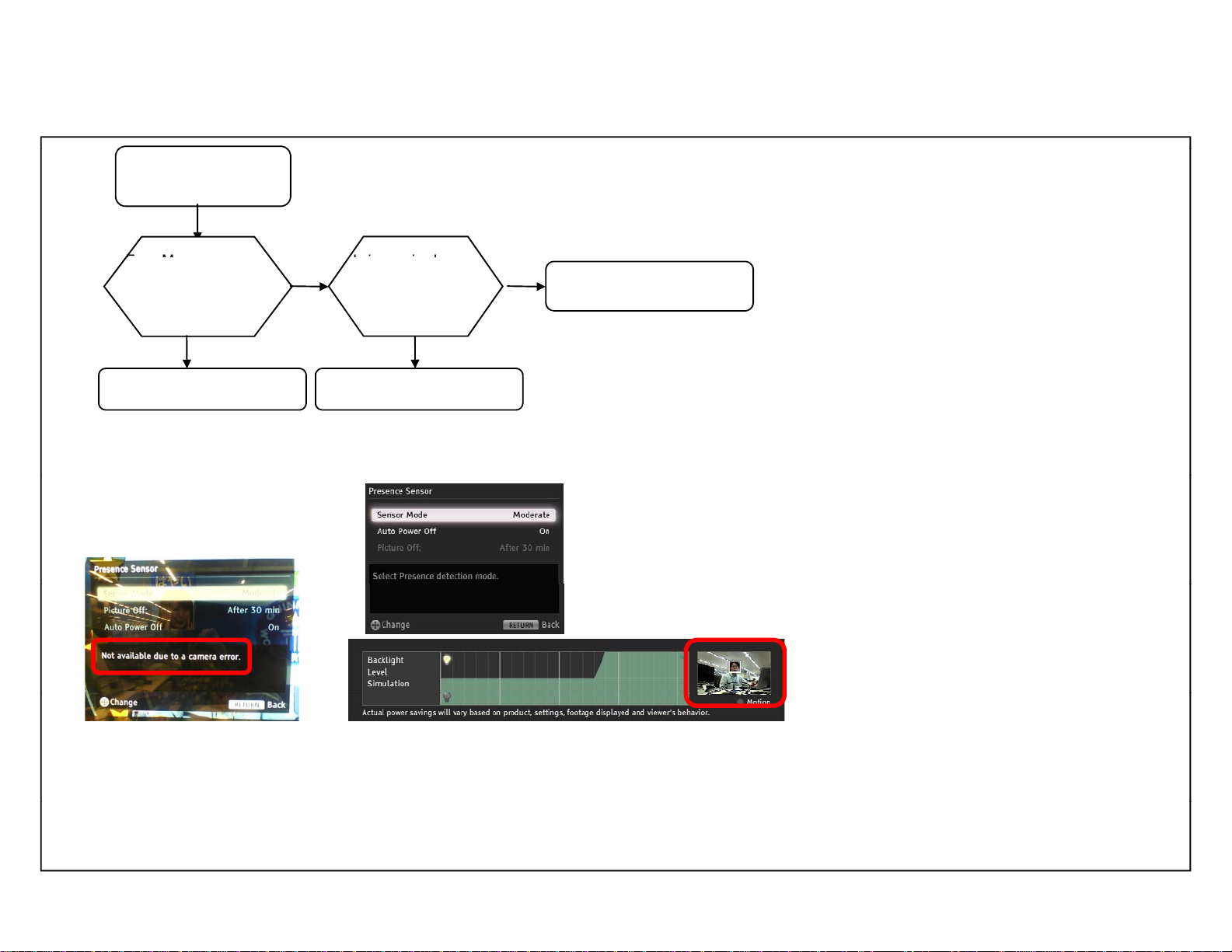
3-8. CAMERA MALFUNCTION
KDL- 22, 32, 40, 46 CX520
RM-GD020, RM-CD013
KDL-32, 40, 46 CX523
RM-GD020
Enter
Presence sensor settings
rror Message appea
when the Presences
Sensor setting?
Yes
Module, Harness Mechanical Problem
No
* Not applicable for these model.
setting menu
at module unit only?
Yes
Setting Menu
Error message
No
Module optical problem
(change module)
image
Presence Sensor Setting:
Press HOME, then select > System Settings > Eco > Presence Sensor
-24-
Self Diagnostic Function
* N
l
p
r
p
Change
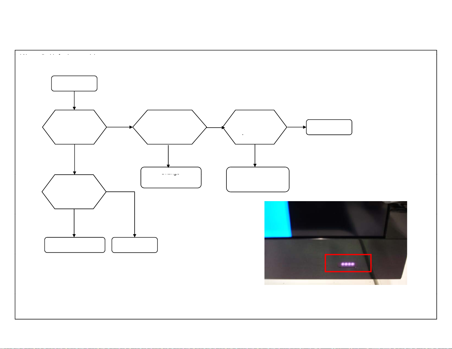
3-9. 3D MALFUNCTION
ot applicable for these mode
3D malfunction
KDL- 22, 32, 40, 46 CX520
RM-GD020, RM-CD013
KDL-32, 40, 46 CX523
RM-GD020
IR has been output
on HEM board,
during 3D displaying.
Replace HEM2 board
Symptom
improvement
HEM2 Board
Check whether
there is interception thing
between Emitte
and glasses.
No Yes
Watching environment
NG
Panel (T-con)
No
Is 3D glasses
ower on?
No
Power on
or
Charge battery
YesYes
3D glasses
[How to confirm IR-output.]
ex) Look IR-LED through CCD/CMOS camera.
-25-
Self Diagnostic Function
Malfunction
pprop
pp p p
in between the
than 32
GB and
All the setups and
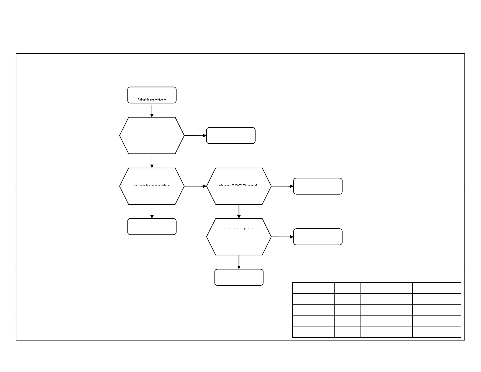
3-10. HDD-Rec MALFUNCTION
KDL- 22, 32, 40, 46 CX520
RM-GD020, RM-CD013
KDL-32, 40, 46 CX523
RM-GD020
HDD Rec
HDD is connected
to the appropriate
USB port?
Yes
USB Hub is inserted
USB port and HDD?
Yes
USB Hub is
NOT supported
No
No
Connect to the
a
riate port
Is the drive size larger
Smaller than 2TB??
Yes
restrictions listed in
iManual are cleared?
Yes
B* board
No
No
Only 32GB~2TB
is supported
Check the iManual
Segment Size B* Board Type G* Board Type
P-2 22 BAT-S GD1
P-2 32 BAT-V G2A
P-2 40 BAT-V G2B
P-2 46 BAT-V G3
-26-
Self Diagnostic Function
NO
Farend
NO
NO
p
ManualFocus
InsertotherCMU
Works?
RepairBATPWB
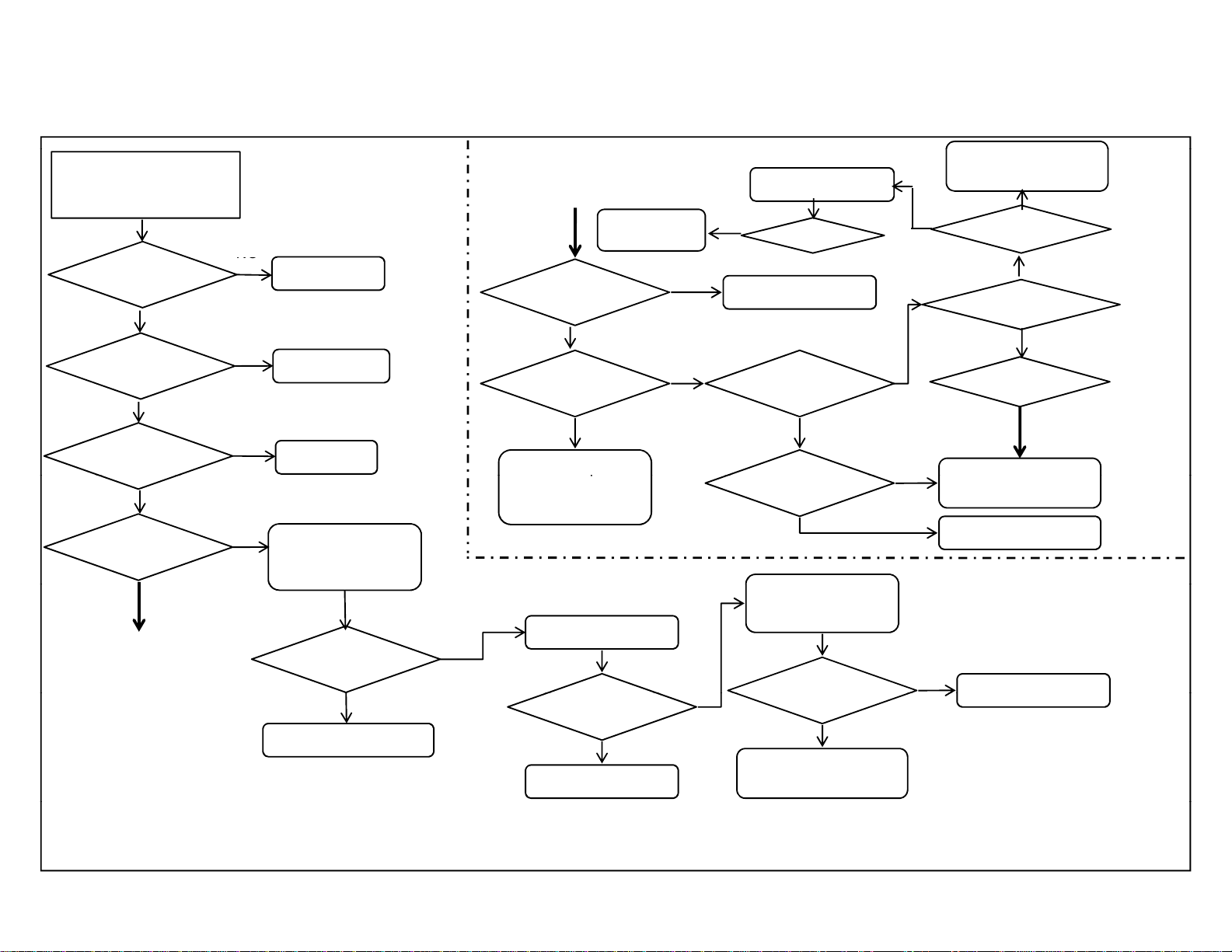
3-11. Skype Trouble Shooting Flow
Problem!
IsitSkype
readyTV?
YES
Doyouhave
CMU‐BR100?
YES
USBplugged?
YES
Abletorun
SkypeApp?
YES
NO
NO
NO
BuyreadyTV
Buy
CMU‐BR100
InsertUSB
‐UnplugotherUSB
device.
‐ACOff/On
* Continue
YES
Spec.USBoverload.
Abletorun
SkypeApp?
NO
* Continue
CMU-BR100
Network
connected?
YES
PIC/AUD
quality?
YES
Networkspeed.
OrFarendsystem
issue.
ChangeUSBport.
Abletorun
SkypeApp?
YES
RepairBATPWB
is NG.
NO
NO
Moveunitaway
fromspeaker.
NG
Testagain.
Donetworksetup
Auto‐Focus
doesn’twork?
YES
work?
BR100orUSB
dongle.
YES
CMU‐BR100isNG.
Swaptonewone.
YES
KDL- 22, 32, 40, 46 CX520
RM-GD020, RM-CD013
KDL-32, 40, 46 CX523
RM-GD020
Farend
setting/system.
NG
OK
CallSkype
soundtest.
Soundquality?
Soundquality?
Novideo?
Novideo
EnoughNET
speed?
Yes
NO
‐
CMU‐BR100isNG.
Swaptonewone.
SPEC.Focusarea.
NO
-27-
3-12. T roubleshooting Reference
-
E
-
E
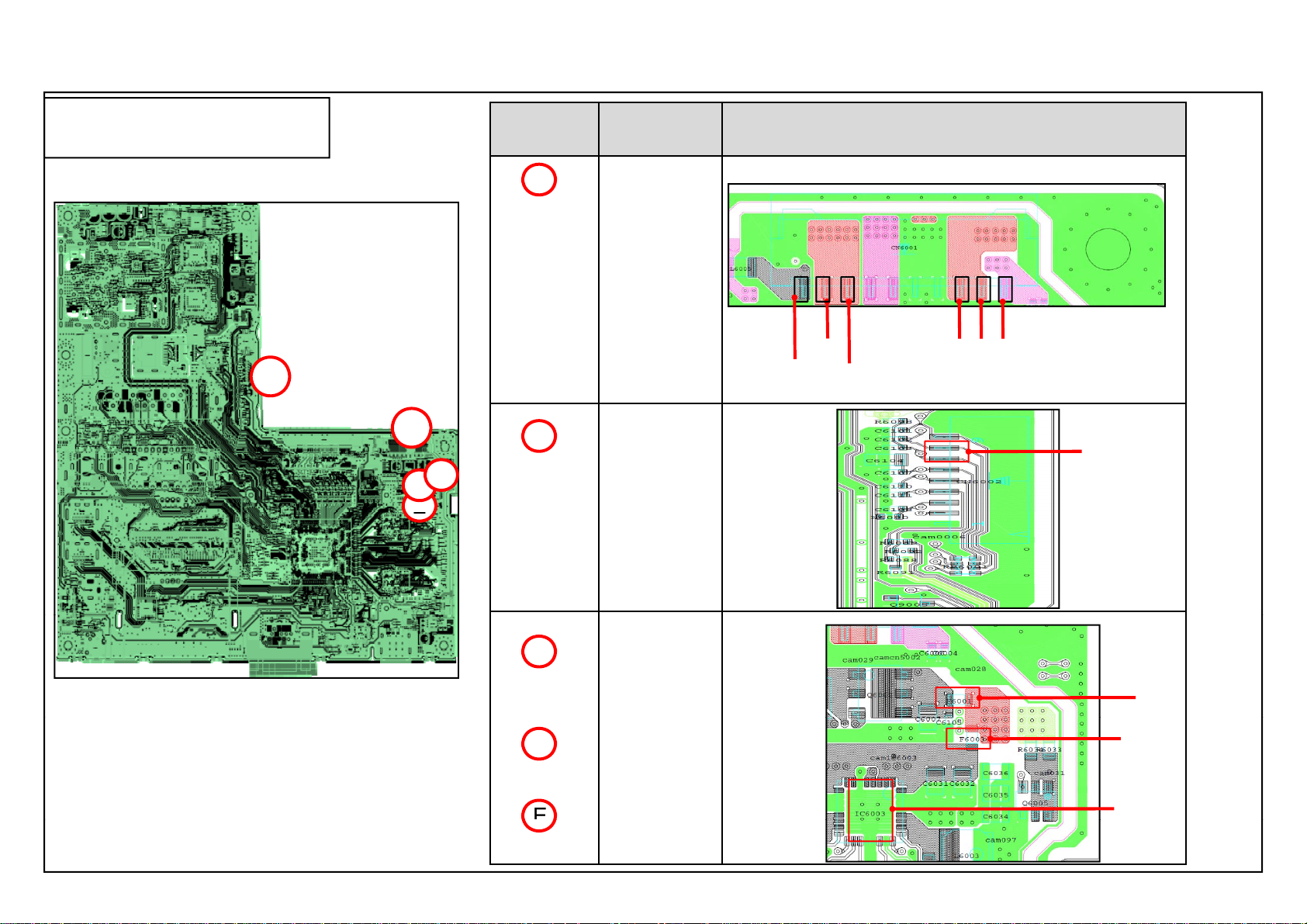
3-12-1. BAT-S ( A Side) (22”)
KDL- 22, 32, 40, 46 CX520
RM-GD020, RM-CD013
KDL-32, 40, 46 CX523
RM-GD020
Note: Refer to each Troubleshooting
for details information.
BAT-S < A Side>
A
B
A
D
C
Parts
Location
A
B
Parts PWB Drawing Parts Location
CN6001
i) Pin 1
ii) Pin 2
iii) Pin 3
iv) Pin 8
CN6001
v) Pin 9
vi) Pin 10
Pin 9
Pin 10
Pin 8
CN6002
i) Pin 7
Pin 3
Pin 1Pin 2
Pin 7
CN6002
BAT
S
C
D
F6001
F6003
IC6003
F6001
F6003
IC6003
– 28 –
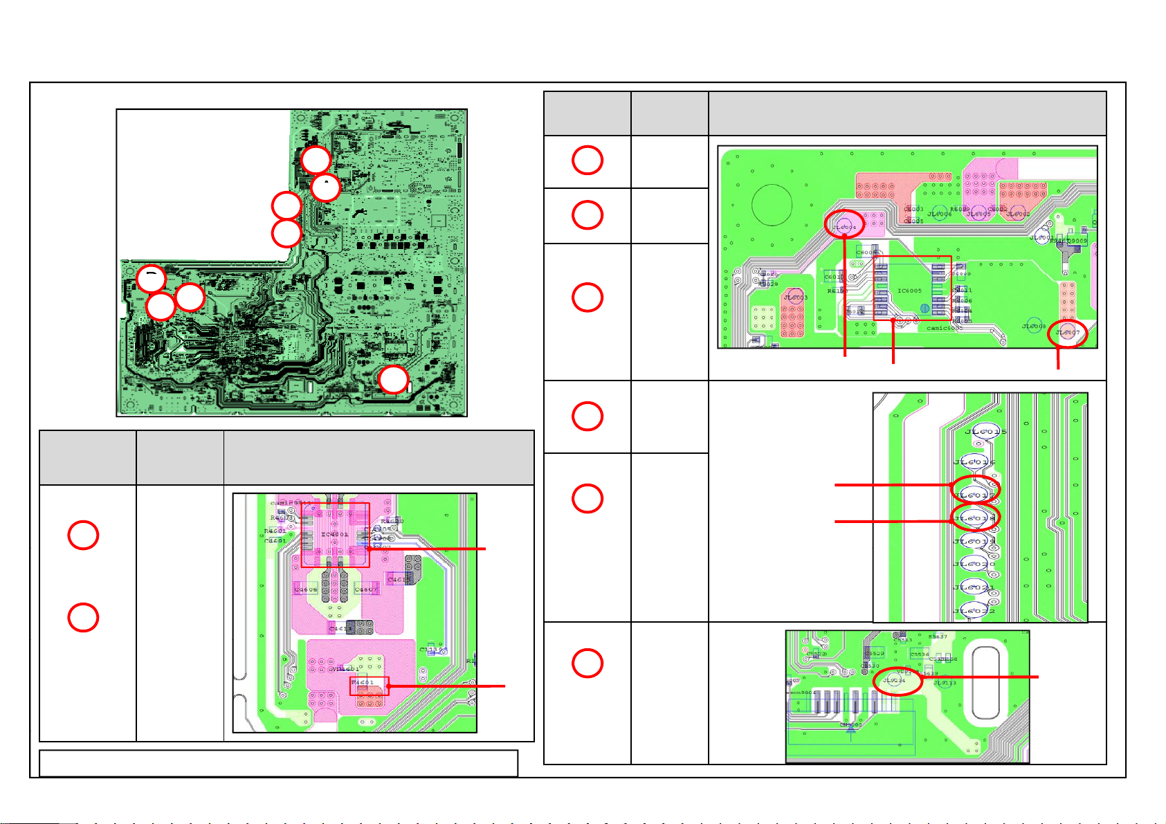
3-12-2. BAT-S ( B Side) (22”)
A
D
L
C
KDL- 22, 32, 40, 46 CX520
RM-GD020, RM-CD013
KDL-32, 40, 46 CX523
RM-GD020
Parts
ocation
A
BAT-S
< B Side>
F
B
B
G
E
C
H
Parts PWB Drawing Parts Location
F4601
c
BAT-S
IC4601
Parts
Location
C
D
E
F
G
Parts PWB Drawing Parts Location
IC6005
*JL6004
JL6007
JL6004 IC6005
*JL6017
(near
F4601)
*JL6018
(near
F4601)
JL6017
JL6018
c
JL6007
B
Note: Parts marked (*) Refer to 3-12-3 for ( Alternative Location) information
IC4601
F4601
– 29 –
H
*JL9234
(near
CN9003)
JL9234
N9003
 Loading...