

Sony KDL-22BX321, KDL-22BX320 User Manual
HISTORY INFORMATION FOR THE FOLLOWING MANUAL:
SERVICE MANUAL
AZ2-UK Chassis
ORIGINAL MANUAL ISSUE DATE: 12/2010
Version Date Subject
1.0 12/21/2010 No revisions or updates are applicable at this time.
2.0 1/25/2011 Added KDL-22BX320 MX/LA models, and KDL-22BX321 Mexico models.
Reissue entire manual.
3.0 7/26/2011 Corrected Ref. numbers for Main Board and Power Supply Board. Replaced page 16.
LCD Digital Color TV
9-883-850-03
SERVICE MANUAL
AZ2-UK Chassis
Self Diagnosis
Supported model
KDL-22BX320
LCD Digital Color TV
9-883-850-03
MODEL LIST
MODEL COMMANDER DESTINATION MODEL COMMANDER DESTINATION
KDL-22BX320 RM-YD065 US/CND
KDL-22BX320 RM-YD065 MX/LA
KDL-22BX321 RM-YD065 MX
TABLE OF CONTENTS
Warnings and Cautions ..................................................................................................................................................................1
Safety-Related Warning ..................................................................................................................................................................3
Safety Check-Out ............................................................................................................................................................................5
Self Diagnosis Functions ...............................................................................................................................................................7
Specications................................................................................................................................................................................11
Sec 1. Software Requirements ....................................................................................................................................................12
1-1. Overview ........................................................................................................................................................................12
1-2. Software Updates ..........................................................................................................................................................12
1-3. Software Update Responsibility.....................................................................................................................................13
1-3-1. Checking the Software Version ............................................................................................................................................... 13
1-3-2. Examples of Software Correctable Symptoms ........................................................................................................................ 13
Sec 2. Disassembly/Part Number Information ...........................................................................................................................14
2-1. Table-Top Stand Assembly Removal .............................................................................................................................14
2-2. Rear Cover, Speakers, Switch Unit, and H Board Removal .........................................................................................15
2-3. A Board, GD8 (Power) Board and Panel Removal .......................................................................................................16
2-4. Cleaning the LCD Panel Assembly................................................................................................................................17
2-5. Screw Legend................................................................................................................................................................17
2-6. Connectors ....................................................................................................................................................................17
2-7. Accessories and Packing ..............................................................................................................................................18
2-8. Remote Commander .....................................................................................................................................................18
2-9. Wire Dressing Diagram .................................................................................................................................................19
KDL-22BX320/22BX321 i
TABLE OF CONTENTS
Sec 3. Service Adjustments .........................................................................................................................................................20
3-1. Accessing Service Adjustment Mode ............................................................................................................................20
3-2. Accessing Factory Adjustment Mode ............................................................................................................................21
3-2-1. Selecting the Panel Code ........................................................................................................................................................ 21
3-2-2. Adjusting the Color Temperature ............................................................................................................................................. 22
Sec 4. Diagrams ............................................................................................................................................................................24
4-1. Circuit Boards Location .................................................................................................................................................24
4-2. Block Diagram ...............................................................................................................................................................25
KDL-22BX320/22BX321 ii
WARNINGS AND CAUTIONS
CAUTION
These servicing instructions are for use by qualied service personnel only. To reduce the risk of electric shock, do not perform any servicing
other than that contained in the operating instructions unless you are qualied to do so.
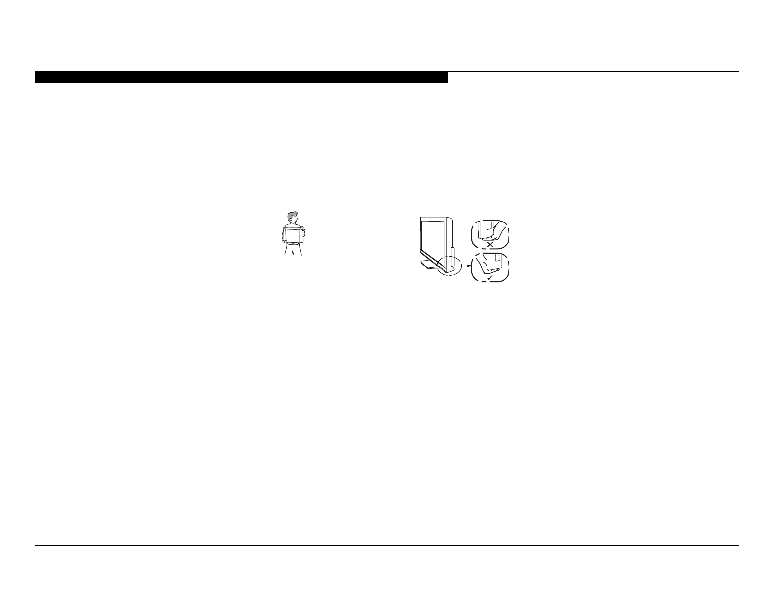
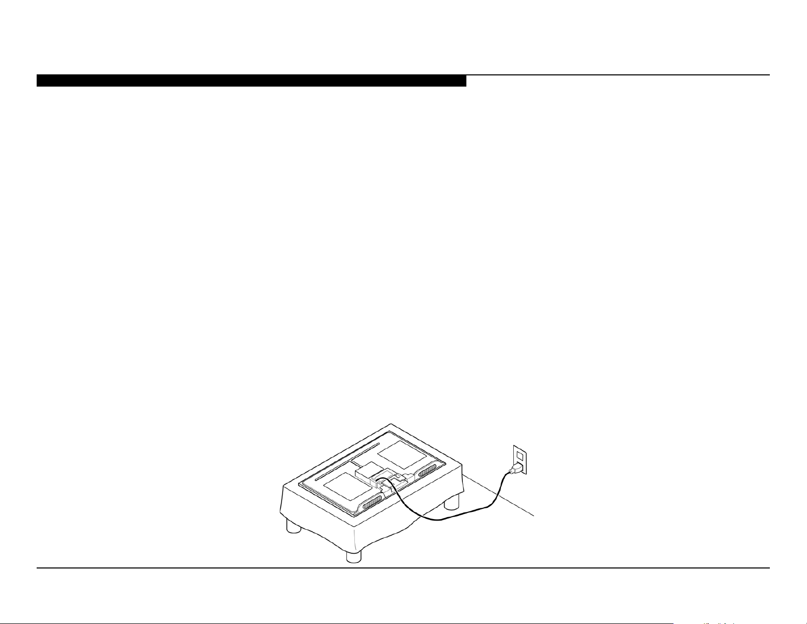
CARRYING THE TV
•Disconnect all cables when carrying the TV.
•Carry the TV with the adequate number of people; larger size TVs require two or more people.
•Correct hand placement while carrying the TV is very important for safety and to avoid
damage.
KDL-22BX320
WARNING!!
An isolation transformer should be used during any service to avoid possible shock hazard, because of live chassis. The chassis of this
receiver is directly connected to the AC power line.
! SAFETY-RELATED COMPONENT WARNING!!
Components identied by shading and ! mark on the exploded views are critical for safe operation.
Replace all components with Sony parts whose part numbers appear as shown in this manual or in supplements published by Sony. It is
essential that all critical parts be replaced only with the part number specied in this manual to prevent electric shock, re, or other hazard.
Circuit adjustments that are critical for safe operation are identied in this manual.
Follow these procedures whenever critical components are replaced or improper operation is suspected.
NOTE: Do not modify the original design without obtaining written permission from the manufacturer or you will void the original parts and
labor guarantee.
KDL-22BX320/22BX321 1
Tenez compte de ce qui suit pendant l’installation du téléviseur :
WARNINGS AND CAUTIONS
ATTENTION!!
Ces instructions de service sont à l’usage du personnel de service qualié seulement. Pour prévenir le risque de choc électrique, ne pas faire
l’entretien autre que celui contenu dans le Mode d’emploi à moins que vous soyez qualié faire ainsi.
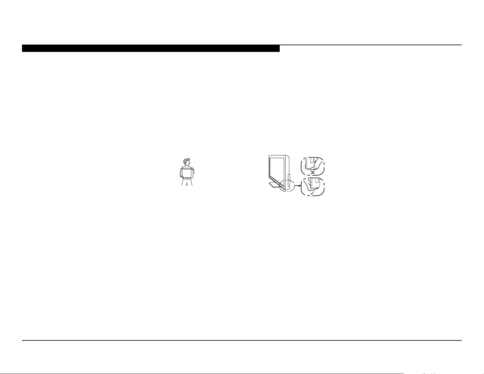
POUR TRANSPORTER LE TÉLÉVISEUR
•Débranchez tous les câbles avant de transporter le téléviseur.
•Transportez le téléviseur avec le nombre de personnes approprié ; un téléviseur de grande
taille doit être transporté par au moins deux personnes.
•Lors du transport du téléviseur, le bon emplacement des mains est très important pour votre
sécurité, ainsi que pour éviter de causer des dommages.
KDL-22BX320
ALERTE!!
An d’eviter tout risque d’electrocution provenant d’un chássis sous tension, un transformateur d’isolement doit etre utilisé lors de tout
dépannage. Le chássis de ce récepteur est directement raccordé à l’alimentation du secteur.
! ATTENTION AUX COMPOSANTS RELATIFS A LA SECURITE!!
Les composants identies par une trame et par une marque ! sur les schemas de principe, les vues explosees et les listes de pieces sont
d’une importance critique pour la securite du fonctionnement. Ne les remplacer que par des composants Sony dont le numero de piece est
indique dans le present manuel ou dans des supplements publies par Sony. Les reglages de circuit dont l’importance est critique pour la
securite du fonctionnement sont identies dans le present manuel. Suivre ces procedures lors de chaque remplacement de composants
critiques, ou lorsqu’un mauvais fonctionnement suspecte.
KDL-22BX320/22BX321 2
SAFETY-RELATED WARNING
USE CAUTION WHEN HANDLING THE LCD PANEL
When repairing the LCD panel, be sure you are grounded by using a wrist band.
When installing the LCD panel on a wall, the LCD panel must be secured using the 4 mounting holes on the rear cover.
1) Do not press on the panel or frame edge to avoid the risk of electric shock.
2) Do not scratch or press on the panel with any sharp objects.
3) Do not leave the module in high temperatures or in areas of high humidity for an extended period of time.
4) Do not expose the LCD panel to direct sunlight.
5) Avoid contact with water. It may cause a short circuit within the module.
6) Disconnect the AC power when replacing the backlight (CCFL) or inverter circuit.
(High voltage occurs at the inverter circuit at 650Vrms.)
7) Always clean the LCD panel with a soft cloth material.
8) Use care when handling the wires or connectors of the inverter circuit. Damaging the wires may cause a short.
9) Protect the panel from ESD to avoid damaging the electronic circuit (C-MOS).
10) During the repair, DO NOT leave the Power On for more than 1 hour while the TV is face down on a cloth.
KDL-22BX320/22BX321 3
SAFETY-RELATED WARNING
AVERTISSEMENTS DE SÉCURITÉ
FAITES ATTENTION LORS DE LA MANIPULATION DE L’ÉCRAN ACL
Au moment de réparer l’écran ACL, assurez-vous d’être mis à la terre à l’aide d’un bracelet à cet effet.
Au moment d’installer le panneau ACL sur un mur, il doit être maintenant en place à l’aide des 4 orices de xation présents au
couvercle arrière.
1) N’appuyez par sur le bord du panneau ou du cadre an d’éviter le risque de choc électrique.
2) Ne rayez pas ou n’appuyez pas sur le panneau avec des objets pointus.
3) Ne laissez pas le module exposé à des températures élevées ou dans des secteurs à haut niveau d’humidité pour une période prolongée.
4) N’exposez pas le panneau ACL à l’ensoleillement direct.
5) Évitez le contact avec l’eau, car elle peut causer un court-circuit dans le module.
6) Déconnectez l’alimentation c.a. au moment de remplacer le rétroéclairage ou le circuit inverseur (Un voltage élevé se produit dans le
circuit inverseur à 650Vrms).
7) Nettoyez toujours le panneau ACL avec un chiffon doux.
8) Faites attention lors de la manipulation des ls ou connecteurs du circuit inverseur. Le fait d’endommager les lms peut causer un court-
circuit.
9) Protégez le panneau des décharges électrostatiques an d’éviter d’endommager le circuit électronique (C-MOS).
10) Pendant la réparation, NE LAISSEZ PAS l’alimentation en fonction pendant plus de 1 heure pendant que l’écran du téléviseur repose sur
un tissu.
KDL-22BX320/22BX321 4
SAFETY CHECK-OUT
To Exposed Metal
Parts on Set
0.15 µF
Earth Ground
AC
Voltmete
r
(0.75V)
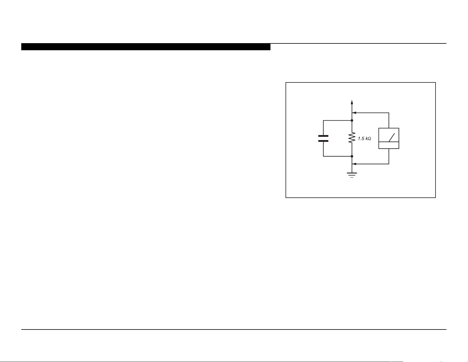
After correcting the original service problem, perform the following safety checks before releasing the set to the customer:
1. Check the area of your repair for unsoldered or poorly soldered connections.
Check the entire board surface for solder splashes and bridges.
2. Check the interboard wiring to ensure that no wires are “pinched” or touching
high-wattage resistors.
3. Check that all control knobs, shields, covers, ground straps, and mounting
hardware have been replaced. Be absolutely certain that you have replaced
all the insulators.
4. Look for unauthorized replacement parts, particularly transistors, that
were installed during a previous repair. Point them out to the customer and
recommend their replacement.
5. Look for parts which, though functioning, show obvious signs of deterioration.
Point them out to the customer and recommend their replacement.
6. Check the line cords for cracks and abrasion. Recommend the replacement
of any such line cord to the customer.
Figure A. Using an AC voltmeter to check AC leakage.
7. Check the antenna terminals, metal trim, “metallized” knobs, screws, and
all other exposed metal parts for AC leakage. Check leakage as described
below.
KDL-22BX320/22BX321 5
SAFETY CHECK-OUT
Trouble Light
AC Outlet Box
Ohmmeter
Cold-water Pipe
LEAKAGE TEST
The AC leakage from any exposed metal part to earth ground and from all
exposed metal parts to any exposed metal part having a return to chassis, must
not exceed 0.5 mA(500 microamperes). Leakage current can be measured by
any one of three methods.
1. A commercial leakage tester, such as the Simpson 229 or RCA WT-540A.
Follow the manufacturers’ instructions to use these instructions.
2. A battery-operated AC milliampmeter. The Data Precision 245 digital
multimeter is suitable for this job.
3. Measuring the voltage drop across a resistor by means of a VOM or
battery-operated AC voltmeter. The “limit” indication is 0.75 V, so analog
meters must have an accurate low voltage scale.
The Simpson’s 250 and Sanwa SH-63TRD are examples of passive VOMs
that are suitable. Nearly all battery-operated digital multimeters that have a
2 VAC range are suitable (see Figure A).
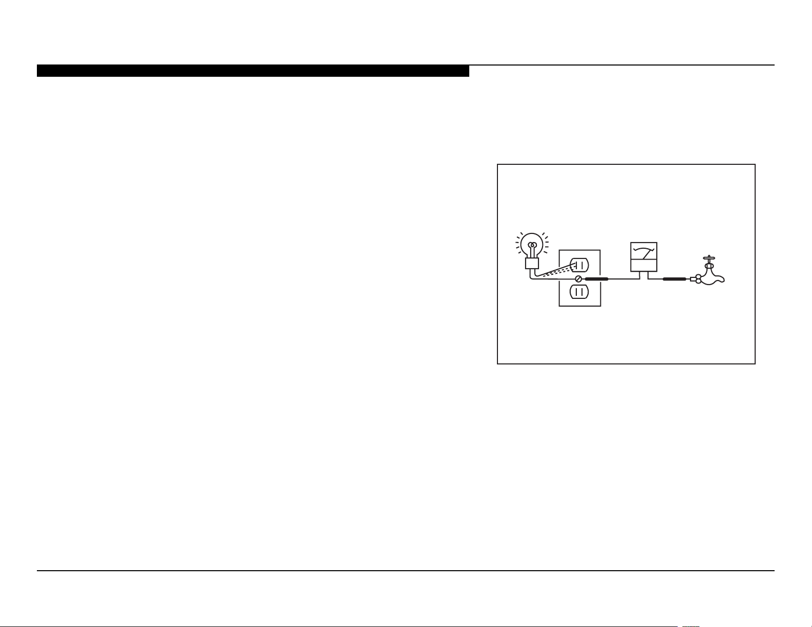
HOW TO FIND A GOOD EARTH GROUND
A cold-water pipe is a guaranteed earth ground; the cover-plate retaining screw
on most AC outlet boxes is also at earth ground.
Figure B. Checking for earth ground.
If the retaining screw is to be used as your earth ground, verify that it is at
ground by measuring the resistance between it and a cold-water pipe with an
ohmmeter. The reading should be zero ohms.
If a cold-water pipe is not accessible, connect a 60-to 100-watt trouble-light (not
a neon lamp) between the hot side of the receptacle and the retaining screw.
Try both slots, if necessary, to locate the hot side on the line; the lamp should
light at normal brilliance if the screw is at ground potential (see Figure B).
KDL-22BX320/22BX321 6
SELF DIAGNOSIS FUNCTIONS
y
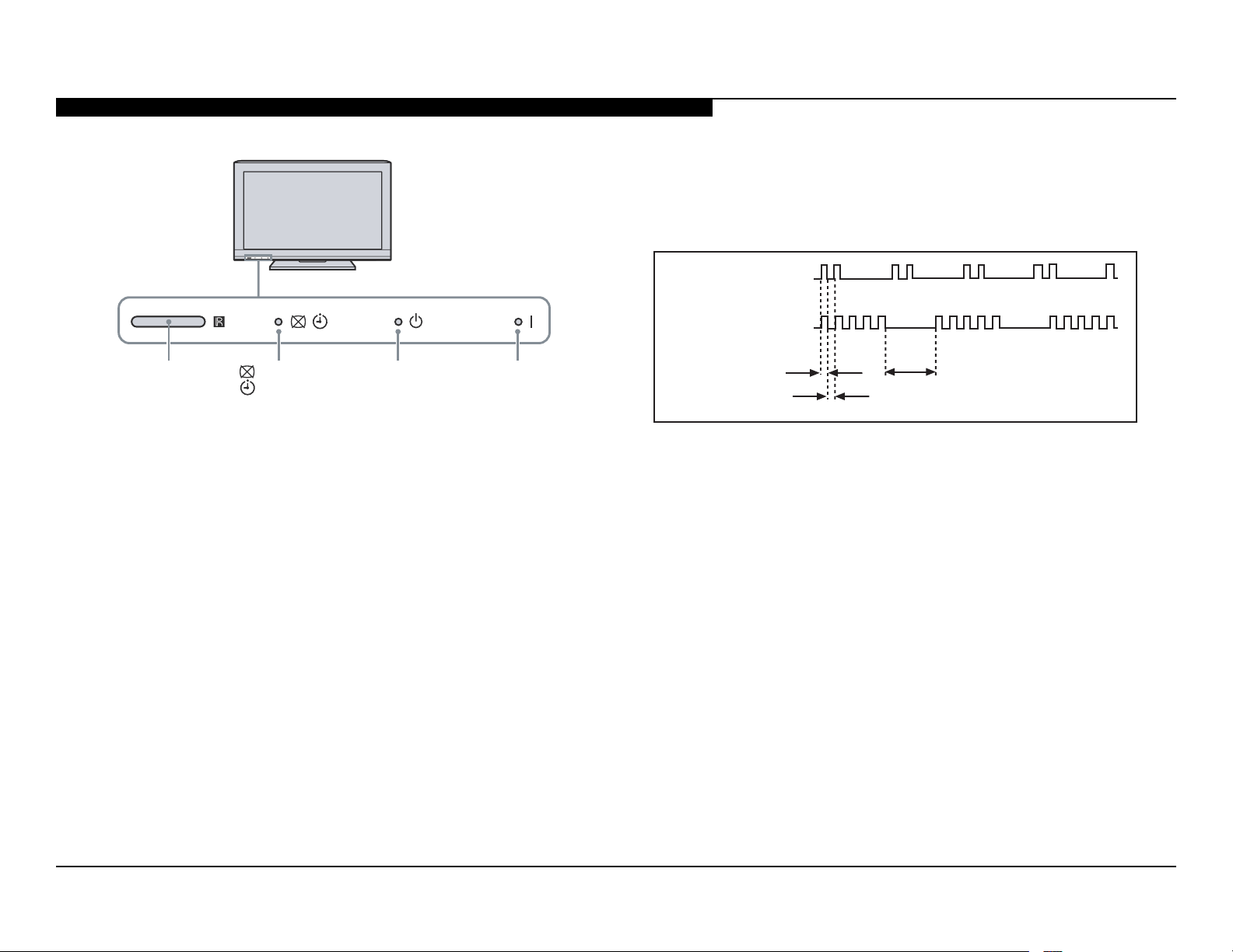
SELF DIAGNOSIS FUNCTION
The units in this manual contain a self-diagnostic function. If an error occurs, the STANDBY LED will automatically begin to ash. The number
of times the LED ashes translates to a probable source of the problem. A denition of the STANDBY LED ash indicators is listed in the
instruction manual for the user’s knowledge and reference. If an error symptom cannot be reproduced, the remote commander can be used to
review the failure occurrence data stored in memory to reveal past problems and how often these problems occur.
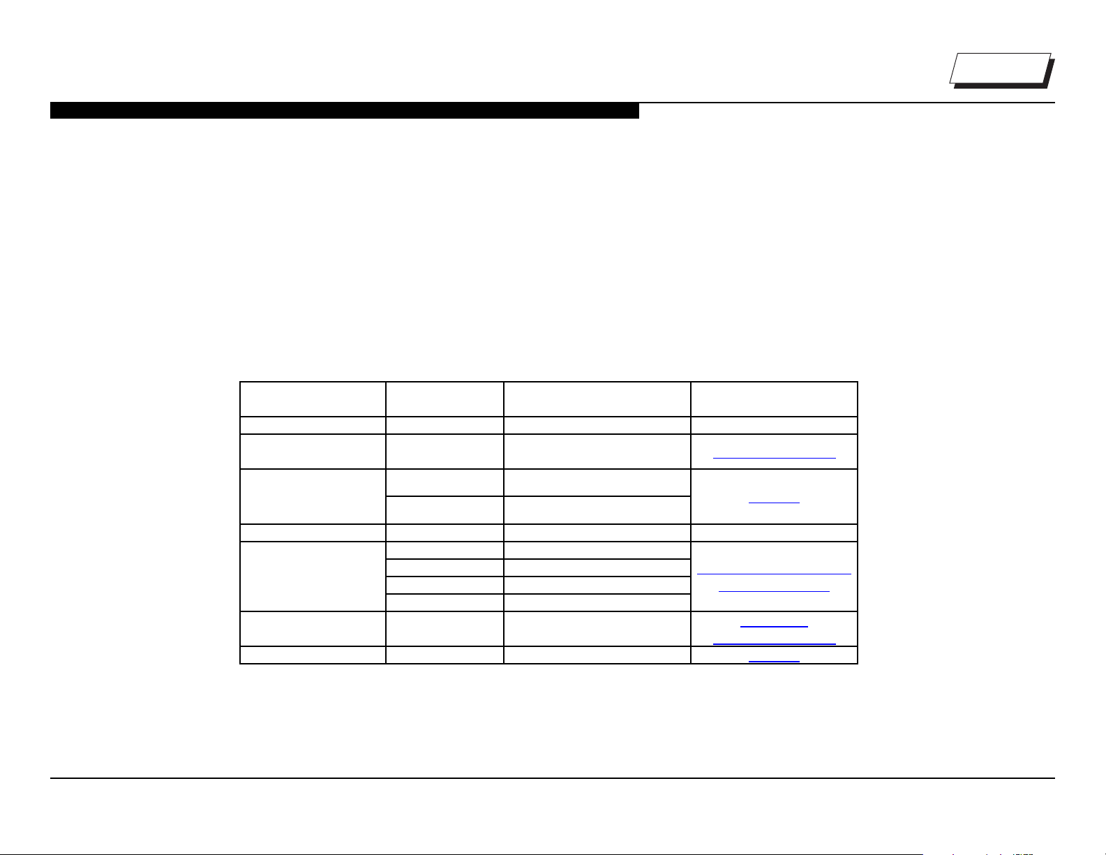
DIAGNOSTIC TEST INDICATORS
When an error occurs, the STANDBY LED will ash a set number of times to indicate the possible cause of the problem. If there is more than
one error, the LED will identify the rst of the problem areas.
Result for all of the following diagnostic items are displayed on screen.
If the screen displays a “0”, no error has occurred .
Self Diagnosis
Supported model
Number of times
Standb
LED blinks
NA RGB_SEN RGB Sensor ACK Error NA
2 MAIN_POWER
3
4 BALANCER Panel Balancer Error NA
5
6 BACKLITE Backlight Error
7 TEMP_ERR Temperature Error A Board
Diagnostic Item Possible Causes Possible Location
Main Power
Over Voltage Protection
AUD_PROT Audio Error Detection
DC_ALERT DTT Error
TCON ERR TCON Error
HFR ERR HFR Error
P_ID_ERR Panel ID NVM Error
PANEL_POWE Panel Error
GD8 (Power) Board
A Board
TCON Control MT Board
LVDS Connection
LCD Panel
GD8 (Power) Board
KDL-22BX320/22BX321 7
STANDBY LED FLASH COUNT
SELF DIAGNOSIS FUNCTIONS
2 times
5 times
(IR) Infrared
Receiver
Picture Off/
Timer LED
Standby LED
Power LED
LED ON 0.3 sec.
LED OFF 0.3 sec.
LED OFF
3 sec.
KDL-22BX320/22BX321 8
VIEWING THE SELF CHECK DIAGNOSTIC LIST
R
R
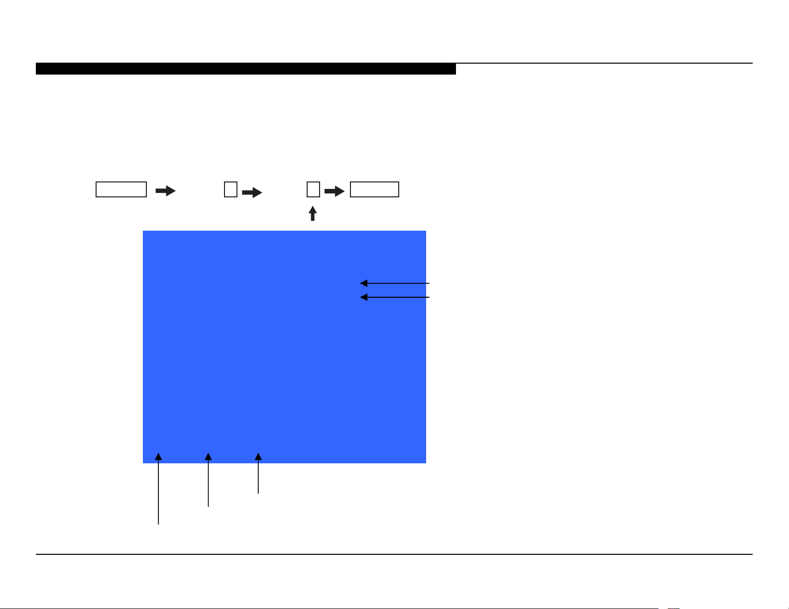
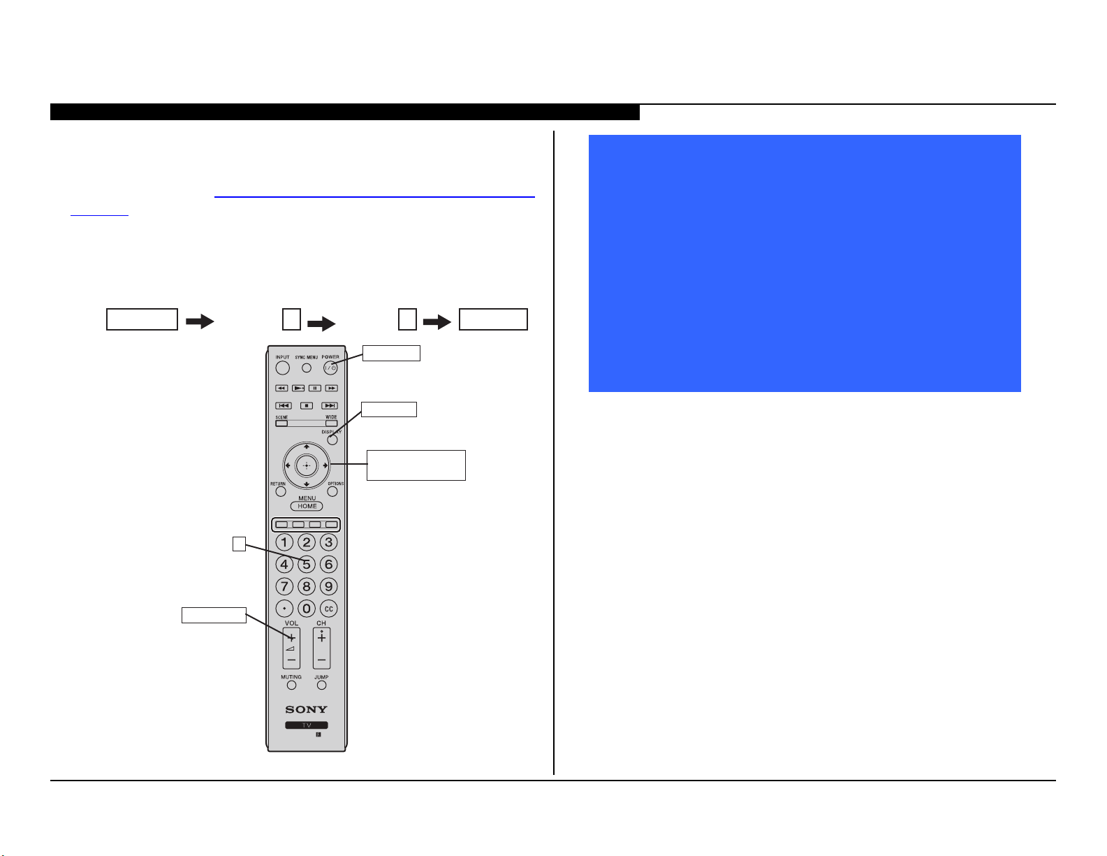
For errors with symptoms such as “power sometimes shuts off” or “screen sometimes goes out” that cannot be conrmed, it is possible to
bring up past occurrences of a failure for conrmation on the Self Check diagnostic screen:
1. TV must be in standby mode. (Power off).
2. Press the following buttons on the Remote Commander within a second of each other:
SELF DIAGNOSIS FUNCTIONS
DISPLAY
* NOTE: This differs from accessing Service Adjustments Mode (Volume +)
Channel 5 Volume -
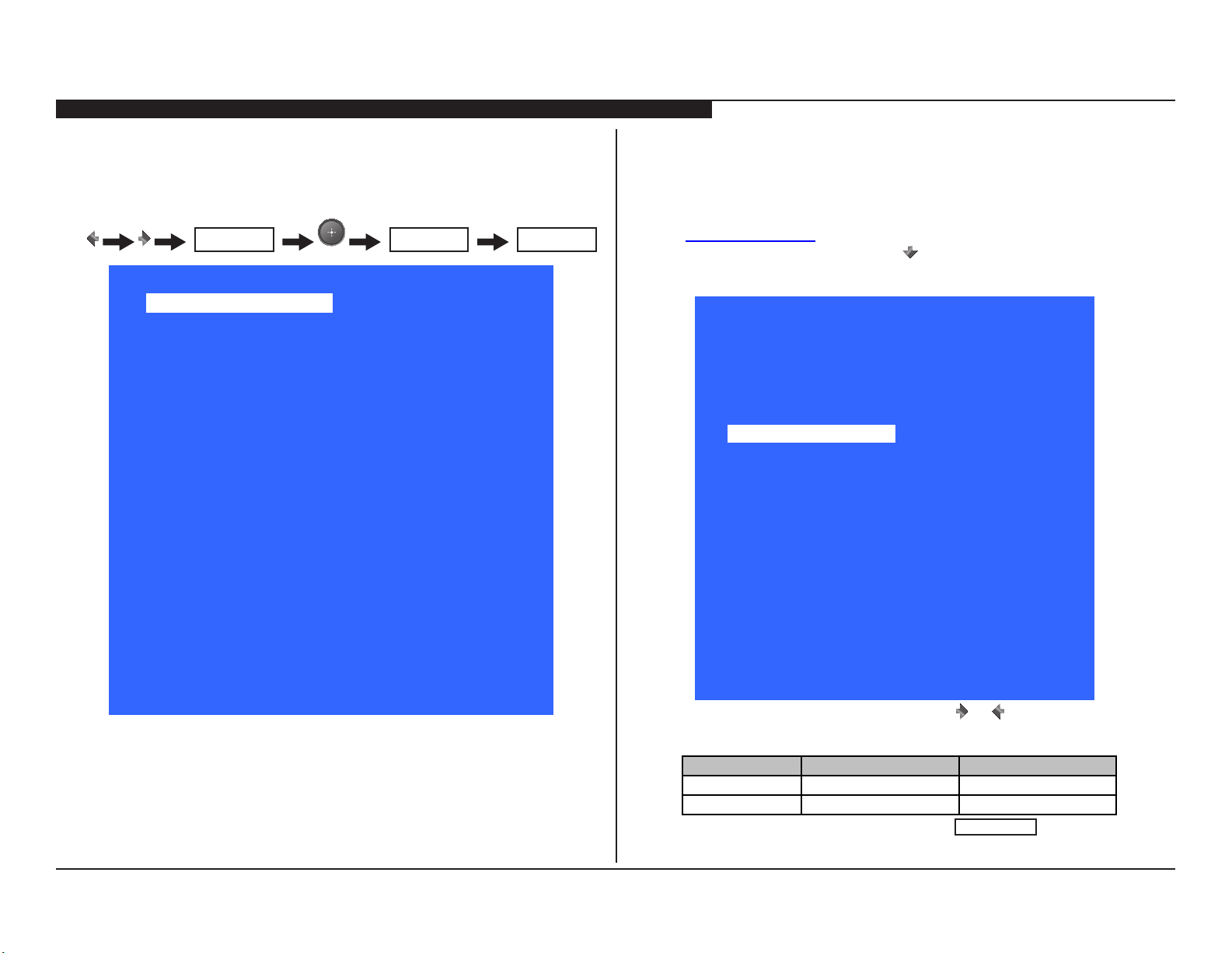
SELF CHECK
Back <<
002 MAIN_POWE 001 001 indicates an error was detected
003 AUD_PORT 000 000 indicates no error was detected
003 DC_ALERT 000
004 BALANCE
005 TCON_ERR 000
005 HFR_ERR 000
005 P_ID_ER
005 PANEL_POWE 000
006 BACKLITE 000
007 TEMP_ERR 000
00000 00010 00000 [Menu] Exit
POWER
000
000
.
Panel Operation Time by Hour (max 99999)
Boot Count (max 99999)
Total Operation Time by Hour (max 99999)
KDL-22BX320/22BX321 9
SELF DIAGNOSIS FUNCTIONS
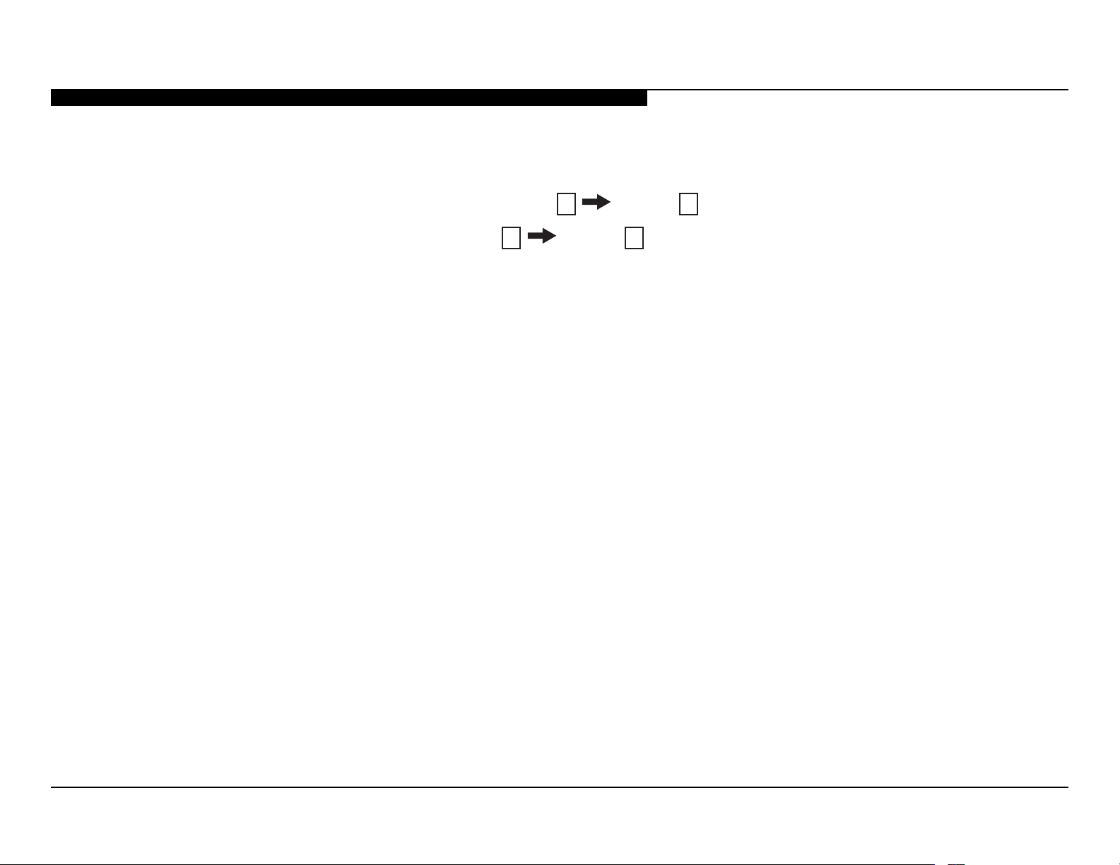
CLEARING THE SELF CHECK DIAGNOSTIC LIST
Since the diagnostic results displayed on the screen are not automatically cleared, always check the self-diagnostic screen after you have
completed the repairs to be sure you have cleared the result display to “0”.
1. To clear the Error history and Error count: Press the Channel 8 Channel 0.
2. To clear the Panel operation time: Press the Channel 7 Channel 0.
EXITING THE SELF CHECK DIAGNOSTIC SCREEN
1. To exit the Self Diagnostic screen, turn off the power to the TV by pressing the POWER button on the remote or the POWER button on
the TV.
KDL-22BX320/22BX321 10

SPECIFICATIONS
Licensing Information
Macintosh is a trademark of Ap
ot
HDM
ar
in
Fer
U.S.
U.S.
Manufa
th
Blu-ray Disc
“BRAVIA”
or
“PlayStati
S
System
Te levision system NTSC: American TV standard
Channel coverage Analog terrestrial: 2 - 69 / Digital terrestrial: 2 - 69
Panel system LCD (L iquid Crystal Dis play) Panel
Speaker output 5 W + 5 W
Input/Output jacks
CABLE/ANTENNA 75-ohm external terminal for RF inputs
VIDEO IN 1/2VID EO : 1 Vp- p, 75 ohms unbalanced, sync negative
COMPONENT IN YP
HDMI IN HDM I: Video: 480i, 480p, 720p, 1080i, 1080p, 1080/24p
AU DIO OUT 500 mVrms (typi cal)
DIGITA L AUDIO OUT
(OPTICAL )
PC IN D- sub 15-pin, analog RGB, 0.7 Vp-p, 75 ohms, posi tive
PC/HDMI IN 1 AUDIO INPUT Stereo mini jack, 500 mV rms, (Typical) / Im pedance: 47 kilohms
Power and others
Power requirement 110-240 V AC, 50/60 Hz (U .S.A./Canada/Mexico 120 V AC, 60 Hz)
Power consumption
in use
in standby Less than 0.28 W with 120 V AC and with 240 V
Screen size
(inches measured diagonally)
Speaker/Full range (2) (mm)
Dimensions with stand (mm)
without stand (mm)
wall-mount hole pattern (mm)
wall-mount screw size (mm) M4 (length: refer Operating Instruction manual)
Mass with stand (kg)
without stand (kg)
Supplied accessories Remote control RM-Y D065 (1)/Size AA batteries (2)/Operating Instructions (1)/Quick Setup Guide
common to all models
individual modelsScrew (7)
Optional accessories Connecting cables / Support Belt Kit / Wall-Mount Bracket: SU-WL100
•Optional accessories availability depends on its stock.
•Design and specications are subject to change without notice.
(inches)
(inches)
(inches)
ATSC (8VSB terr estrial): ATSC compli ant 8V SB
QAM on cable: ANS I/SC TE 07 2000 (D oes not include CableCARD functionality)
Analog Cable: 1 - 135 / Di gital Ca ble: 1 - 135
AUDI O: 500 mVrms (Typical) / Impedance: 47 kilohms
BP R (Component Video): Y: 1.0 Vp-p, 75 ohms unbalanced, sync negative / PB : 0.7 Vp- p, 75 ohms
R
P
: 0.7 Vp- p, 75 ohms / Signal format: 480i, 480p, 720p, 1080i, 1080p
AUDI O: 500 mVrms (Typical) / Impedance: 47 kilohms
Audio: Two channel linear PCM 32, 44.1 and 48 kHz, 16, 20 and 24bits, Dolby Digital
PC Input (see Operating Instruction manual)
PCM/ Dolby Digital optical signal
See the PC Input Si gnal Reference Chart for PC and HDMI IN in Operating Instruction manual)
W 55
AC less than 0.40 W
22
40 × 100
5
(1
/8 × 4)
22BX321: 551 × 393 × 190
21 3/4 × 15 1/2 × 7 1/2
22BX320: 551 × 393 × 215
3
21
/4 × 15 1/2 × 8 1/2
551 × 363 × 61
3
21
/4 × 14 3/8 × 2 1/2
001 × 001
(lb.)
(lb.)
(1)/Warranty Card (1)/Safety and Regulatory Booklet (1)/Software License (1)/Stand installatio n
guide (1)/Table-Top Stand (1 set)
6.2
13.7
5.6
12.4
)lacitrev( senil 867 × )latnoziroh( stod 883,1 noituloser yalpsiD
her countries.
ple Inc., registered in the U.S. and
I, the HDMI logo, and High-Definition Multimedia Interface
e trademarks or registered trademarks of HDMI Licensing, LLC
the United States and other countries.
gason Patent Properties, LLC:
Patent No. 5,717,422
Patent No. 6,816,141
ctured under license from Dolby Laboratories. Dolby and
e double-D symbol are trademarks of Dolby Laboratories.
is a trademark.
and , BRAVIA Sync, and are trademarks
registered marks of Sony Corporation.
on” is a registered trademark and “PS3” is a trademark of
ony Computer Entertainment Inc.
®
Your BRAVIA TV is ENERGY STAR
in the “Home” mode. It meets strict energy
efficiency guidelines set by the U.S.
qualified
Environmental Protection Agency and
Department of Energy.
ENERGY STAR is a joint program of these
government agencies, designed to promote energy
efficient products and practices. Changes to certain features,
settings, and functionalities of this TV (i.e. Picture/Sound, Power
Savings) can increase or change the power consumption. Dependin g
upon such changed settings, the power consumption may exceed the
limits required for the ENERGY STAR qualification in the “Home”
mode.
KDL-22BX320/22BX321 11
SEC 1. SOFTWARE REQUIREMENTS
1-1. OVERVIEW
The models in this manual utilize a “generic” type main board. In
the past, many different main boards needed to be stocked due to
differences in software requirements. The software loaded on the
board was specic to the model and its features along with the type
of LCD panel installed during production.
Replacement main boards are now stocked with basic software.
Once the replacement board is installed in the unit, the most current
software needs to be installed using a USB thumb drive containing
the necessary software downloaded.
This new method of supplying main boards signicantly reduces the
complexity of replacing LCD panels and main boards. Information
about the LCD panel is stored on the TCON circuits. This information
is automatically loaded onto the main board when the TV is powered
up. With the correct software version the main board and/or the
TCON or LCD panel can be replaced more efciently. The software
update and procedures for the software installation are located on
the Sony Authorized Servicer Portal at www.sony.com/asp.
In addition to software installation, service adjustment information
may need to be modied or veried to complete the service of the
TV. Service adjustment information is covered in Sec 3. Service
Adjustments on page 20.
1-2. SOFTWARE UPDATES
The subject of software updates is a very important. The televisions
of today have advanced to the point where they are not simply a
television anymore. They are evolving into devices that are designed
to integrate with numerous other devices found in the home. Some
examples are: Portable audio and video devices, still cameras, home
computer networks and accessing the internet to name a few.
Communications with these varying devices requires that the
television be compatible with varying communications protocols.
Although standards are detailed for each of these protocols, the real
world dictates that occasional errors may occur that could prevent
devices from operating or communicating properly.
Keeping the software in the television up-to-date is a procedure that
is normally handled by the owner of the television. Most customers
who own computers and other digital devices are familiar with and are
accustomed to updating the software in their products. If a customer
contacts the Sony Customer Support Center and it is deemed to
be correctable with a software update, the issue is handled at the
customer level.
Software updates can be performed by:
• Customer Manual Downloads: Software updates can be
accessed by the customer from the Sony Support Site at http://
esupport.sony.com where they can be downloaded and placed
on a USB thumb drive to be loaded onto the TV. The instructions
for downloading the software le vary from chassis to chassis
and sometimes from model to model. The customer is provided
with the instructions to properly format the USB thumb drive,
unzip the le, and the procedures for loading the software into
the television.
KDL-22BX320/22BX321 12
SEC 1. SOFTWARE REQUIREMENTS
1-3. SOFTWARE UPDATE RESPONSIBILITY
Software updates are designed to be performed by the customer.
Warranty repairs in which the issue can be resolved by a software
update are not reimbursable. Most issues involving software
updates are handled by the customer service center and should not
be directed to an authorized service center. It is the responsibility
of the servicer to prevent service calls for issues that involve
software updates. Exceptions to this are certain cases whereby the
customer is unable or unwilling to perform the task. In this situation,
the servicer will be notied and receive the proper authorization for
reimbursement.
It is the servicer’s responsibility, however, to make certain that any
TV requiring a legitimate service is running the latest software
version and to install it if necessary.
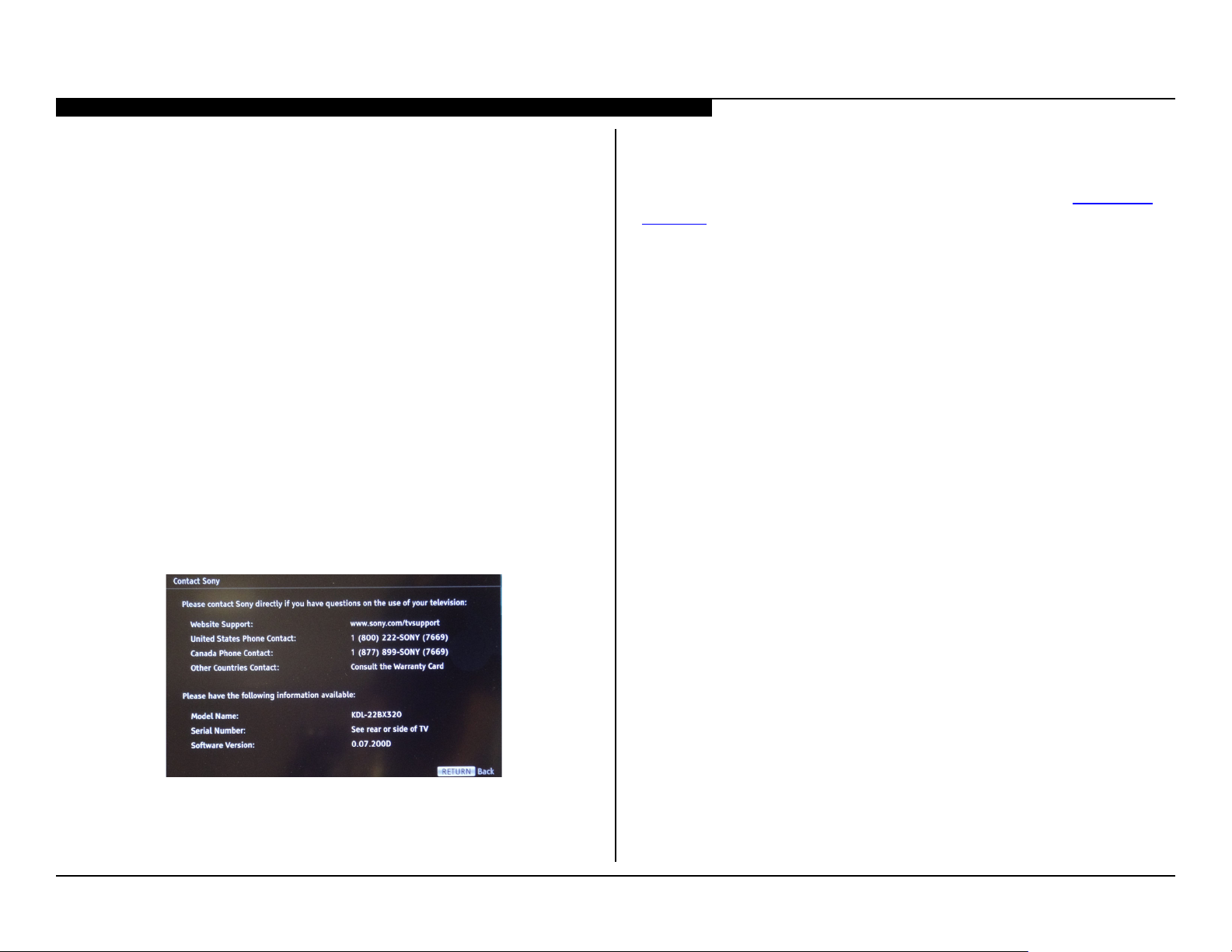
1-3-1. CHECKING THE SOFTWARE VERSION
The easiest way to check the version of software that is currently on
the TV is to access the Contact Sony screen by using the customer
menu.
1-3-2. EXAMPLES OF SOFTWARE CORRECTABLE
SYMPTOMS
Always check the Sony Authorized Servicer Portal at www.sony.
com/asp site for any known and/or listed issues that are software
related. Most symptoms that are correctable by software updates
involve communications issues with other devices or minor glitches
in the operation of a specic function. Below is a list of some of the
symptoms that may be corrected with a software update:
Î Fluctuations in picture brightness
Î Intermittent picture freezing or noise
Î Problems with certain inputs (especially HDMI)
Î Intermittent or distorted audio
Î Erratic remote control operation
Î Unit turns on and off by itself
Î Loss of color
Î Internet connectivity
Î Certain features not working correctly
(photo or video le viewing)
SAMPLE SOFTWARE VERSION ON THE CONTACT SONY SCREEN
KDL-22BX320/22BX321 13

SEC 2. DISASSEMBLY/PART NUMBER INFORMATION
2-1. TABLE-TOP STAND ASSEMBLY REMOVAL
Remove 3 screws from Table-Top Stand Assembly
A
Lift up TV set to detach from Table-Top Stand Assembly
B
Components not identied by a part number or
description are not stocked because they are seldom
required for routine service.
NOTE: The components identied by shading
and ! mark are critical for safety. Replace only
with part number specied.
The component parts of an assembly are indicated by the
reference numbers in the far right column of the parts list
and within the dotted lines of the diagram.
NOTE: Les composants identies per un trame et
une marque ! sont critiques pour la securite.
Ne les remplacer que par une piece portant le
numero specie.
Items marked with an asterisk are not stocked since
*
they are seldom required for routine service. Expect
some delay when ordering these components.
NOTE: The components identied by a red outline and a mark contain
condential information. Specic instructions must be adhered to whenever
these components are repaired and/or replaced.
See Appendix A: Encryption Key Components in the back of this manual.
(Check the Sony Authorized Servicer Portal at www.sony.com/asp for any additional service related issues for this model.)
1
A
B
4
5
Gently place the TV set face down onto a soft cloth
C
Soft Cloth
2
3
C
REF. NO. PART NO. DESCRIPTION [ASSEMBLY INCLUDES] REF. NO. PART NO. DESCRIPTION [ASSEMBLY INCLUDES]
1 X-2580-705-1 BASE (S3B) ASSY
(KDL-22BX320 ONLY)
1 X-2580-706-1 BASE (S5B) ASSY
(KDL-22BX321 ONLY)
2 4-266-619-01 COVER, NECK (S3B)
3 4-266-620-01 NECK (S5)
4 4-159-298-01 SCREW, +PSW M4X10
(SCREWS TO ATTACH NECK TO BASE ASSY)
5 2-580-608-01 SCREW, +PSW M5X16
(SCREWS TO ATTACH TABLE-TOP STAND TO LCD TV)
For product protection and safety reasons, Sony strongly recommends
that you use the screws provided with the TV
CAUTION: These screws cannot be used to secure the TV to
the Wall Mount Brackets
2-580-608-01 SCREW, +PSW M5X16
KDL-22BX320/22BX321 14
SEC 2. DISASSEMBLY/PART NUMBER INFORMATION
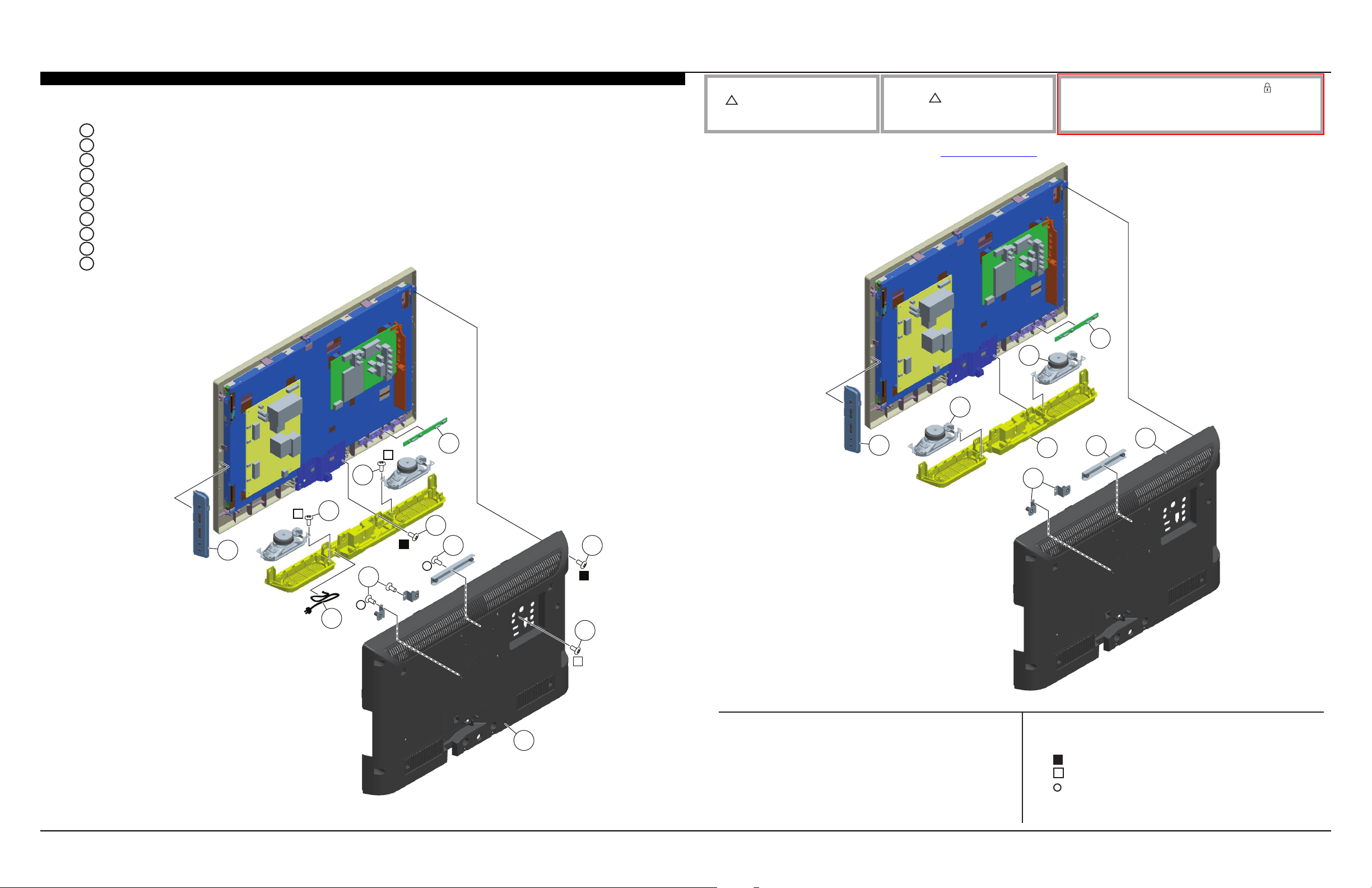
2-2. REAR COVER, SPEAKERS, SWITCH UNIT, AND H BOARD REMOVAL
Remove 6 screws from Rear Cover
A
Remove 2 screws Terminal and Side Jack position
B
Lift up Rear Cover to detach from Bezel
C
Remove 1 screw to detach Vesa Bracket (GW22T) from Rear Cover
D
Remove 2 screws to detach Vesa Brackets (GW22B) from Rear Cover
E
Lift up AC Power Cord and disconnect 1 connector from GD8 Board to detach from Under Cover
F
Remove 2 screws to detach Under Cover from Bezel
G
Remove 8 screws from Speakers to detach from Under Cover
H
Release clips and disconnect 1 connector to detach H Board from LED Guide
I
Lift up Switch Unit and disconnect 1 connector to detach from Bezel
J
NOTE: The components identied by shading
and ! mark are critical for safety. Replace only
with part number specied.
NOTE: Les composants identies per un trame et
une marque ! sont critiques pour la securite.
Ne les remplacer que par une piece portant le
numero specie.
NOTE: The components identied by a red outline and a mark contain
condential information. Specic instructions must be adhered to whenever
these components are repaired and/or replaced.
See Appendix A: Encryption Key Components in the back of this manual.
(Check the Sony Authorized Servicer Portal at www.sony.com/asp for any additional service related issues for this model.)
56
55
55
I
H
H
G
J
E
F
D
C
A
B
REF. NO. PART NO. DESCRIPTION [ASSEMBLY INCLUDES] REF. NO. PART NO. DESCRIPTION [ASSEMBLY INCLUDES]
51 4-270-687-01 REAR COVER (GW22)
52 4-270-698-01 BRACKET, VESA (GW22T)
53 4-266-623-01 BRACKET, VESA (GW22B)
54 4-264-687-01 COVER, UNDER (GW22)
55 1-858-339-21 LOUDSPEAKER (4X10CM)
57
54
53
56 1-857-898-21 H BOARD, MOUNTED
57 1-489-627-11 SWITCH UNIT
2-580-637-01 SCREW, +BVST 4X12
7-685-648-79 SCREW +BVTP 3X12 TYPE2 IT-3
7-685-647-79 SCREW +BVTP 3X10 TYPE2 IT-3
52
51
KDL-22BX320/22BX321 15
SEC 2. DISASSEMBLY/PART NUMBER INFORMATION
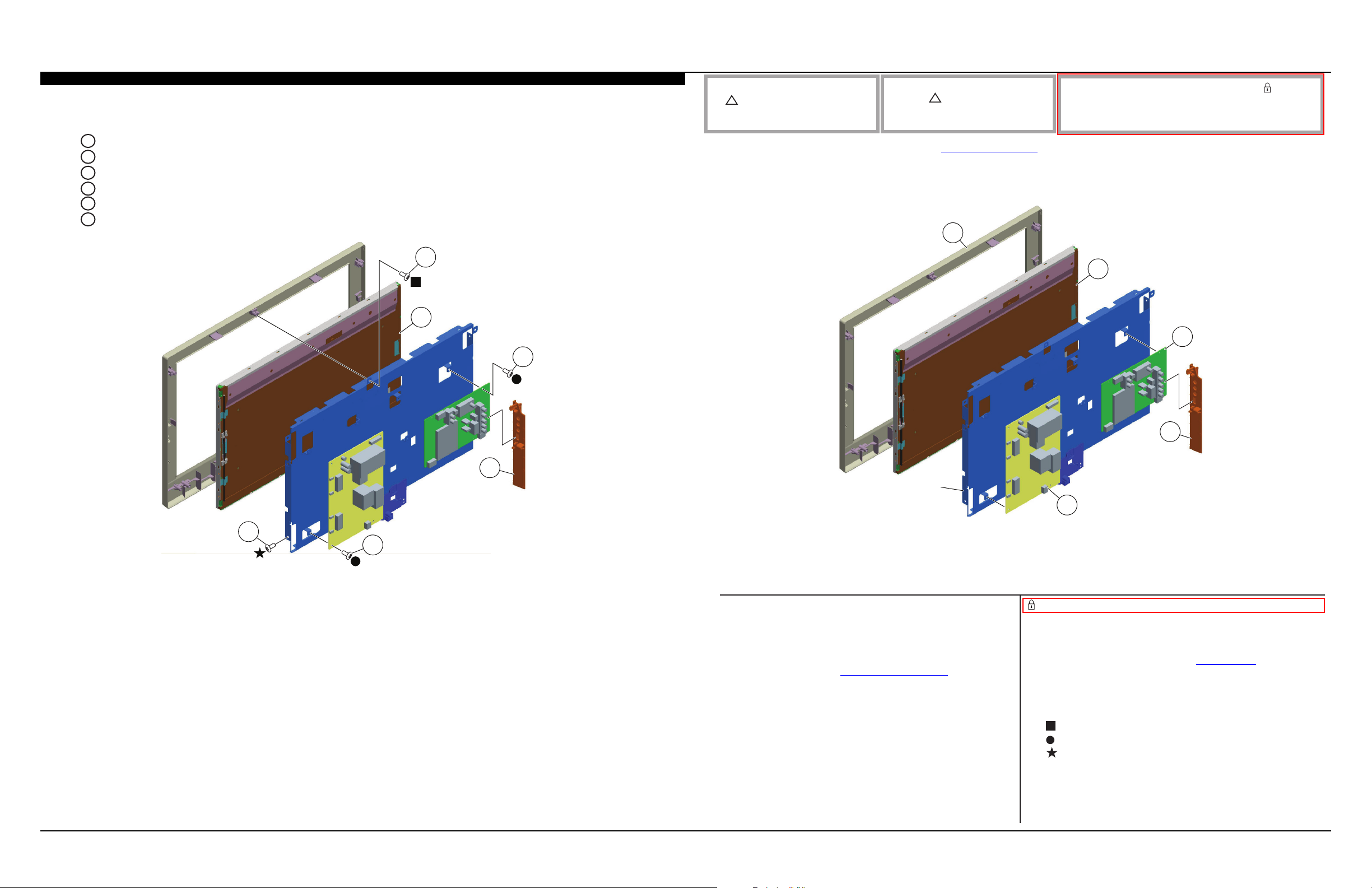
2-3. A BOARD, GD8 (POWER) BOARD AND PANEL REMOVAL
A
Remove 4 screws and disconnect 5 connectors from A Board to detach from Panel Bracket
B
Release 2 clips and slide-out Side Jack Bracket to detach from A Board
Remove 5 screws and disconnect 5 connectors from GD8 (Power) Board to detach from Panel Bracket
C
Remove 4 screws from Panel Bracket to detach from Panel
D
Remove 1 screw from Panel Bracket to detach from Bezel
E
Carefully Lift up Panel to remove from Bezel
F
E
F
NOTE: The components identied by shading
and ! mark are critical for safety. Replace only
with part number specied.
NOTE: Les composants identies per un trame et
une marque ! sont critiques pour la securite.
Ne les remplacer que par une piece portant le
numero specie.
NOTE: The components identied by a red outline and a mark contain
condential information. Specic instructions must be adhered to whenever
these components are repaired and/or replaced.
See Appendix A: Encryption Key Components in the back of this manual.
(Check the Sony Authorized Servicer Portal at www.sony.com/asp for any additional service related issues for this model.)
101
102
103
A
104
B
Panel
Bracket
105
D
C
REF. NO. PART NO. DESCRIPTION [ASSEMBLY INCLUDES] REF. NO. PART NO. DESCRIPTION [ASSEMBLY INCLUDES]
101 4-270-686-11 BEZEL (GW22) (FOR US/CND ONLY)
101 4-270-686-21 BEZEL (GW22) (FOR MX ONLY)
102 NA LCD PANEL
FOR ALL LCD PANEL PART NUMBER INFORMATION
REFER TO THE LCD PANELS SERVICE MANUAL
103 1-857-903-11 A BOARD, COMPLETE
After replacing the Main Board or the LCD Panel, you must update
the software to the latest version. Instructions for updating the
software are included with the software package on the
Sony Authorized Servicer Portal at www.sony.com/asp website
104 4-264-318-01 BRACKET, SIDE (US) (GW)
105 1-857-895-11 GD8 (POWER) BOARD, COMPLETE
2-580-637-01 SCREW, +BVST 4X12
2-580-592-01 SCREW, +PSW M3X8
4-256-393-01 SCREW, +PSW M3X6 W12
KDL-22BX320/22BX321 16
SEC 2. DISASSEMBLY/PART NUMBER INFORMATION
SWITCH UNIT
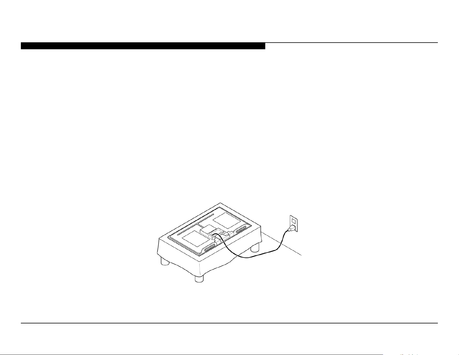
2-4. CLEANING THE LCD PANEL ASSEMBLY
CAUTION: When cleaning the TV, be sure to unplug the power cord to avoid any chance of electric shock.
Clean the cabinet of the TV with a dry soft cloth.
Wipe the LCD screen gently with a soft cloth.
® Stubborn stains may be removed with a cloth slightly moistened with a solution of mild soap and warm
water.
® If using a chemically pretreated cloth, please follow the instruction provided on the package.
® Never use strong solvents such as a thinner, alcohol or benzine for cleaning.
® Periodic vacuuming of the ventilation openings is recommended to ensure the proper ventilation.
2-5. SCREW LEGEND
KDL-22BX320/22BX321
P/N DESCRIPTION REMARKS TOTAL
2-580-637-01 SCREW, +BVST 4X12 RC(6), UNDER COVER(2), PANEL BRKT to BEZEL(1) 9
■
7-685-648-79 SCREW +BVTP 3X12 TYPE2 IT-3 TRMNL AREA(1), RC to SIDE JACK BRKT(1), LEFT SPKR(4), RIGHT SPKR(4) 10
□
4-159-298-01 SCREW, +PSW M4X10 NECK to BASE ASSY(3) 3
▼
2-580-608-01 SCREW, +PSW M5X16 TABLE-TOP STAND(3) 3
▽
2-580-592-01 SCREW, +PSW M3X8 A BOARD(4), GD8 BOARD(5) 9
●
7-685-647-79 SCREW +BVTP 3X10 TYPE2 IT-3 VESA BRKTS to RC(3) 3
○
4-256-393-01 SCREW, +PSW M3X6 W12 PANEL BRKT to PANEL(4) 4
★
NOTE: The components identied by shading
and ! mark are critical for safety. Replace only
with part number specied.
NOTE: Les composants identies per un trame et
une marque ! sont critiques pour la securite.
Ne les remplacer que par une piece portant le
numero specie.
NOTE: The components identied by a red outline and a mark contain
condential information. Specic instructions must be adhered to whenever
these components are repaired and/or replaced.
See Appendix A: Encryption Key Components in the back of this manual.
(Check the Sony Authorized Servicer Portal at www.sony.com/asp for any additional service related issues for this model.)
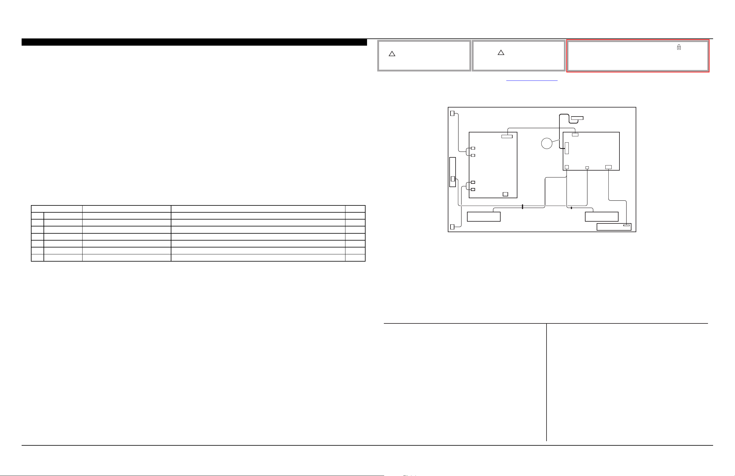
2-6. CONNECTORS
CN204
CN203
CN202
CN201
GD8
CN101
CN1
151
CN4151
CN8151
CN202
CN950
A
H
CN901
SPSP
CN9101
REF. NO. PART NO. DESCRIPTION [ASSEMBLY INCLUDES] REF. NO. PART NO. DESCRIPTION [ASSEMBLY INCLUDES]
151 1-910-103-37 CONNECTOR ASSY 22 FFC 30P
KDL-22BX320/22BX321 17

SEC 2. DISASSEMBLY/PART NUMBER INFORMATION
2-7. ACCESSORIES AND PACKING
3-299-071-05 FLYER, SAFETY (SPANISH VERIONS)
4-275-988-11 GUIDE, QUICK SET UP (ENGLISH VERSION)
4-275-988-21 GUIDE, QUICK SET UP (FRENCH VERSION)
4-275-988-31 GUIDE, QUICK SET UP (SPANISH VERISON)
4-270-476-11 MANUAL, INSTRUCTION (ENGLISH VERSION)
4-270-476-21 MANUAL, INSTRUCTION (FRENCH VERSION)
4-270-476-31 MANUAL, INSTRUCTION (SPANISH VERSION)
!
1-838-979-11 POWER SUPPLY CORD (WITH CORE)
* 4-275-368-11 SUPPLEMENT(STAND INSTALLATION) (SPANISH VERISON)
4-159-298-01 SCREW, +PSW M4X10
(SCREWS TO ATTACH NECK TO BASE ASSY)
2-580-608-01 SCREW, +PSW M5X16
(SCREWS TO ATTACH TABLE-TOP STAND TO LCD TV)
For product protection and safety reasons, Sony strongly recommends
that you use the screws provided with the TV
CAUTION: These screws cannot be used to secure the TV to
the Wall Mount Brackets
2-8. REMOTE COMMANDER
1-489-459-11 REMOTE COMMANDER (RM-YD065)
KDL-22BX320/22BX321 18
SEC 2. DISASSEMBLY/PART NUMBER INFORMATION
2-9. WIRE DRESSING DIAGRAM
KDL-22BX320/22BX321 19
SEC 3. SERVICE ADJUSTMENTS
t
3-1. ACCESSING SERVICE ADJUSTMENT MODE
This set does not use Service Mode for adjustments. To make
adjustments, refer to 3-2. Accessing Factory Adjustment Mode on
page 21. You can access the Self diagnosis history page from Service
Mode.
1. TV must be in Standby mode. (Power On).
2. Press the following buttons on the Remote Commander
within a second of each other:
DISPLAY
Channel 5 Volume +
POWER
DISPLAY
Onscreen cursor
and select button
POWER
Service Mode
Sound Adjust… >>
Wide Band Tuning >>
Range Scan… >>
Self diagnosis history >>
Status Information… >>
LVDS Spectrum(%0) <[ 20 ]>
DPMS <[ Off ]>
Low of HPD <[ 5 ]>
TVD_MCDONE_CNT <[ 20 ]>
Demo Special >>
Bypass AVI Info Detec
Panel Selection <[ W-CM22 ]>
3. To exit service mode, turn the power off.
<[ Off ]>
[</>]Set [Menu] Exit
Sample Service Menu
5
VOLUME+
RM-YD065
KDL-22BX320/22BX321 20
SEC 3. SERVICE ADJUSTMENTS
r
V
y
r
V
y
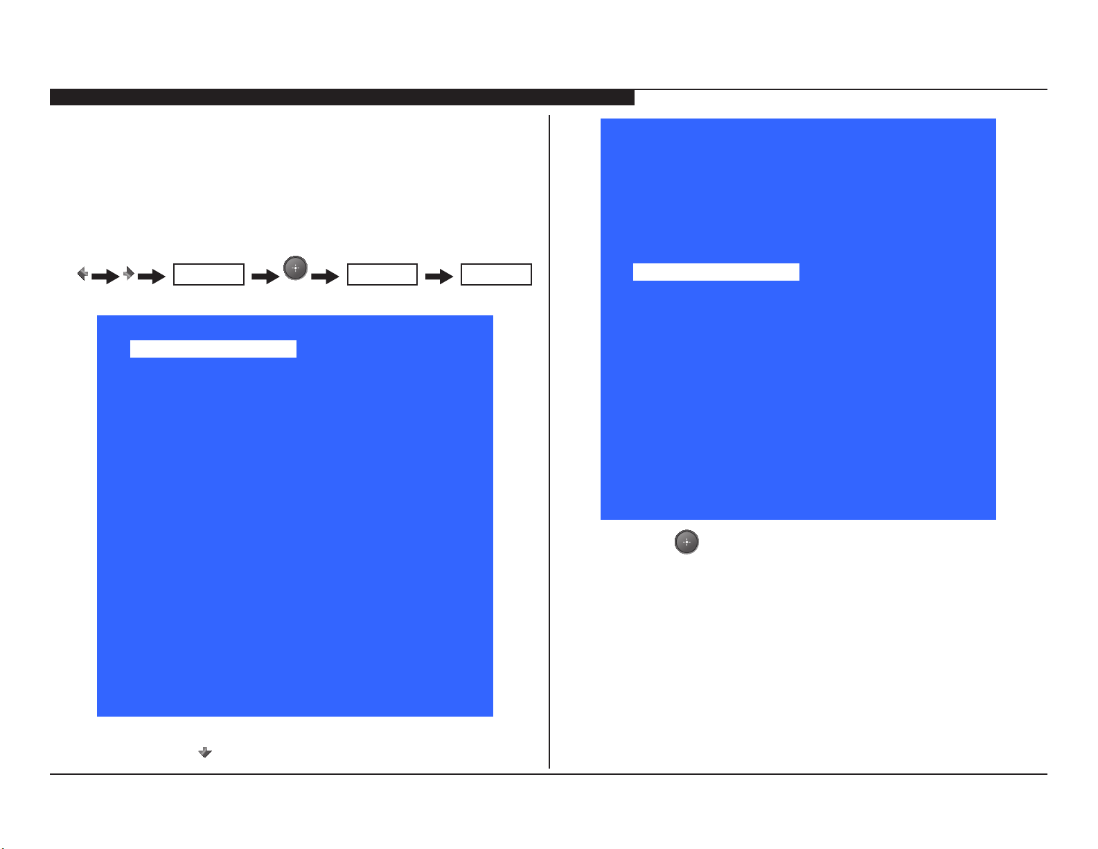
3-2. ACCESSING FACTORY ADJUSTMENT MODE
1. TV must be ON.
2. Press the following buttons on the Remote Commander
within a second of each other:
Input Source <[ TV ]>
Aging Mode <[ Off ]>
Internal Pattern <[ Off ]>
EDID WP Protection
Site Air Channels <[ Off ]>
Site Cable Channels <[ Off ]>
Panel_ID Off
Color Temp >>
ADC Calibration Off
Factory Reset (limited) <[ Off ]>
Auto Phase <[ Off ]>
Factory Reset (default) <[ Off ]>
System 0.07.200D
Model Name KDL-22BX320
Serial Numbe
Picture Quality PQ1.003
Audio Qualit
Panel W_CM22
Panel Info MT0001.0025.00007V2
MUTING
Factory Mode
See rear or side of T
AQ4.0002
Sample Factory Menu
MUTING
[</>]Set [Menu] Exit
MENU
3-2-1. SELECTING THE PANEL CODE
After replacing the main Board or the LCD Panel, you must update the
software to the latest version and then select the Panel ID from Factory
Mode. Instructions for updating the software are included with the
software package on the Sony Authorized Servicer Portal at:
.
www.sony.com/asp.
3. In Factory Mode, use the button to scroll down to select
Panel_ID.
Factory Mode
Input Source <[ TV ]>
Aging Mode <[ Off ]>
Internal Pattern <[ Off ]>
EDID WP Protection
Site Air Channels <[ Off ]>
Site Cable Channels <[ Off ]>
Panel_ID Off
Color Temp >>
ADC Calibration Off
Factory Reset (limited) <[ Off ]>
Auto Phase <[ Off ]>
Factory Reset (default) <[ Off ]>
System 0.07.200D
Model Name KDL-22BX320
Serial Numbe
Picture Quality PQ1.003
Audio Qualit
Panel W_CM22
Panel Info MT0001.0025.00007V2
4. Using the table below, press the or Onscreen cursor
buttons to select the Panel_ID.
See rear or side of T
AQ4.0002
[</>]Set [Menu] Exit
Model Name Panel Code Panel ID
KDL-22BX320 C216B1-L03 W_CM22
KDL-22BX321 C216B1-L03 W_CM22
4. To exit Factory Mode, press the
RETURN
button.
KDL-22BX320/22BX321 21
SEC 3. SERVICE ADJUSTMENTS
r
V
y
r
V
y
3-2-2. ADJUSTING THE COLOR TEMPERATURE
The default White Balance data values are set for optimal viewing. The
following instructions are for technicians who have been requested to
customize calibrations for their customers.
1. TV must be ON.
2. Press the following buttons on the Remote Commander
within a second of each other:
Input Source <[ TV ]>
Aging Mode <[ Off ]>
Internal Pattern <[ Off ]>
EDID WP Protection
Site Air Channels <[ Off ]>
Site Cable Channels <[ Off ]>
Panel_ID Off
Color Temp >>
ADC Calibration Off
Factory Reset (limited) <[ Off ]>
Auto Phase <[ Off ]>
Factory Reset (default) <[ Off ]>
System 0.07.200D
Model Name KDL-22BX320
Serial Numbe
Picture Quality PQ1.003
Audio Qualit
Panel W_CM22
Panel Info MT0001.0025.00007V2
MUTING
Factory Mode
See rear or side of T
AQ4.0002
MUTING
MENU
Factory Mode
Input Source <[ TV ]>
Aging Mode <[ Off ]>
Internal Pattern <[ Off ]>
EDID WP Protection
Site Air Channels <[ Off ]>
Site Cable Channels <[ Off ]>
Panel_ID Off
.
Color Temp >>
ADC Calibration Off
Factory Reset (limited) <[ Off ]>
Auto Phase <[ Off ]>
Factory Reset (default) <[ Off ]>
System 0.07.200D
Model Name KDL-22BX320
Serial Numbe
Picture Quality PQ1.003
Audio Qualit
Panel W_CM22
Panel Info MT0001.0025.00007V2
See rear or side of T
AQ4.0002
[</>]Set [Menu] Exit
4. Press to access Color Temp adjustments.
[</>]Set [Menu] Exit
3. Using the button, scroll down to select Color Temp.
KDL-22BX320/22BX321 22

SEC 3. SERVICE ADJUSTMENTS
Factory Mode
--Color Temperature--
Back >>
Color Temp <[ Cool ]>
R Gain <[ 443 ]>
G Gain <[ 443 ]>
B Gain <[ 443 ]>
R Offset <[ 512 ]>
G Offset <[ 512 ]>
B Offset <[ 512 ]>
Recall Data <[ Off ]>
Data Backup <[ Off ]>
[</>]Set [Menu] Exit
5. Press the or buttons to select the Color Temp type.
(Cool, Neutral, Warm1, or Warm2.)
6. After the correct Color Temperature is selected, press the
to select the Temperature type that needs to be modied.
7. After the correct Temperature type is selected, press the
to increase the data value, or press to decrease the data
value.
8. Complete the data value adjustments to the remaining
temperature items within the selected temperature type.
NOTE: Changes to the data value must be saved within the
Temperature type selected before making changes to one of
the other Temperature types.
9. To save the changes, press the to select Data Backup,
then press .
Factory Mode
--Color Temperature--
Back >>
Color Temp <[ Cool ]>
R Gain <[ 443 ]>
G Gain <[ 443 ]>
B Gain <[ 443 ]>
R Offset <[ 512 ]>
G Offset <[ 512 ]>
B Offset <[ 512 ]>
Recall Data <[ Off ]>
Data Backup <[ W/B ]>
[</>]Set [Menu] Exit
10. Do one of the following:
a. To make changes to one of the other Temperature types,
repeat steps 5 through 9.
b. To exit Factory mode, press
POWER
NOTE: The other categories listed in the Factory Mode menu
will be covered in the training manual for these models.
KDL-22BX320/22BX321 23
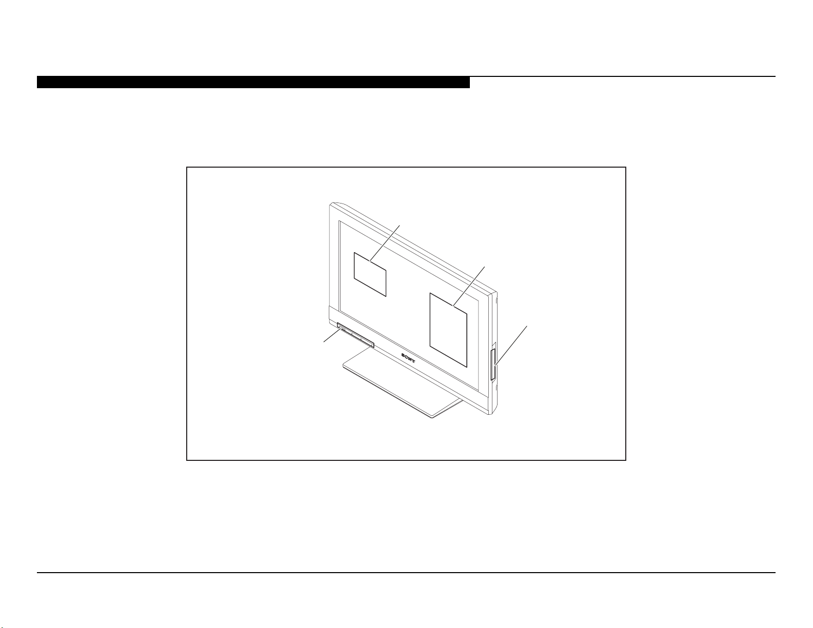
SEC 4. DIAGRAMS
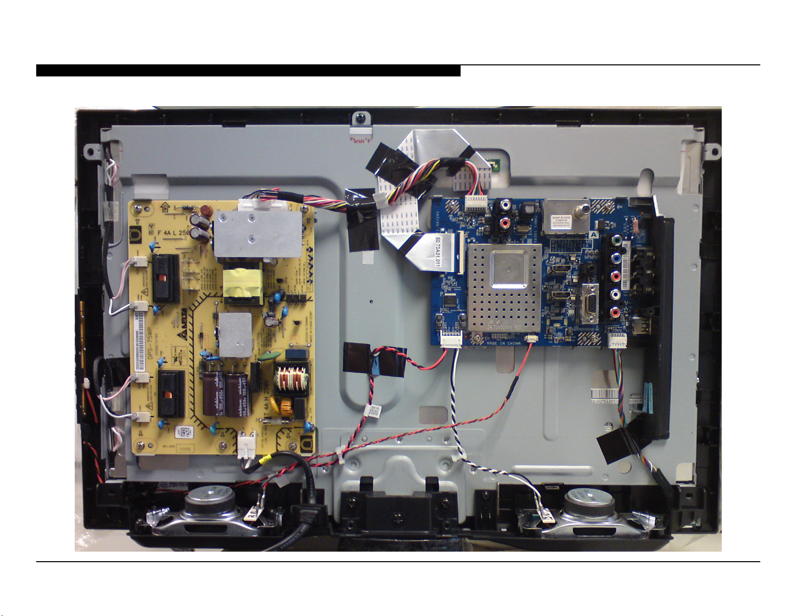
4-1. CIRCUIT BOARDS LOCATION
A
H
GD8
SWITCH UNIT
KDL-22BX320/22BX321 24
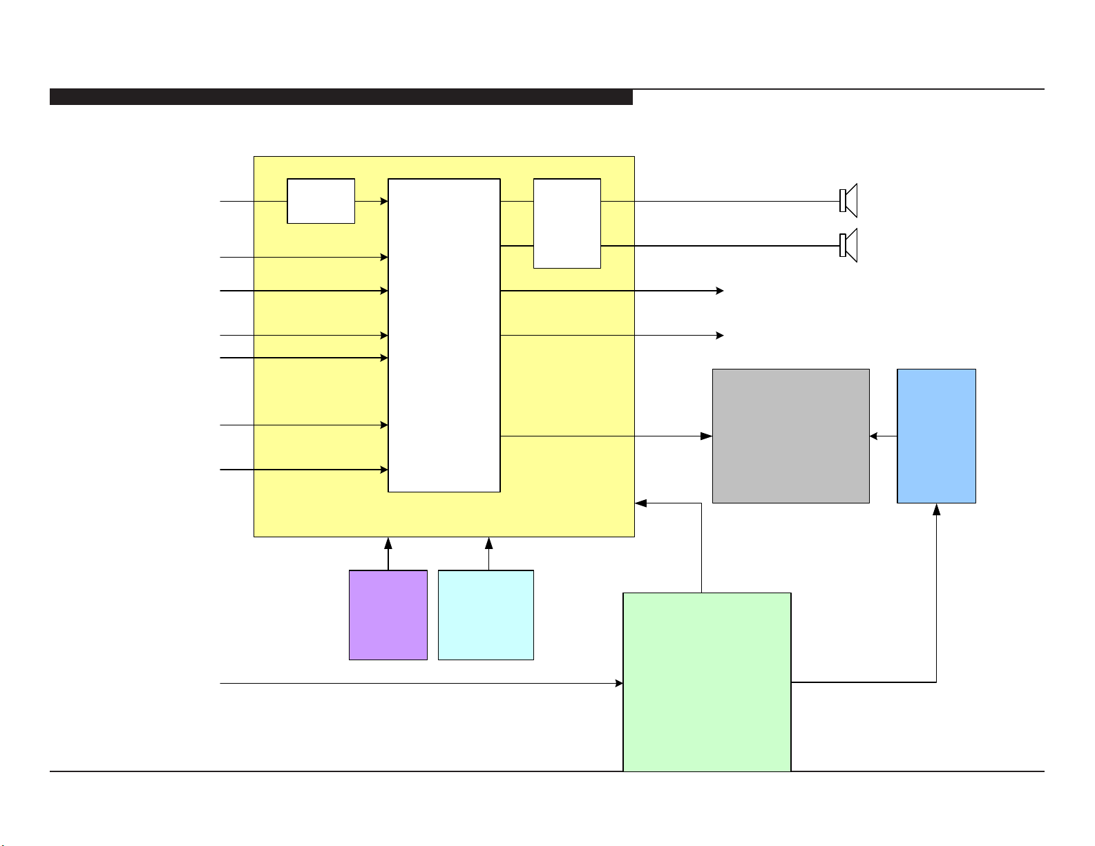
4-2. BLOCK DIAGRAM
SEC 4. DIAGRAMS
RF
COMPOSITE OR
COMPONENT 1
COMPONENT 2
HDMI 1
HDMI 2
PC HD15
USB2.0
TUNER
U3
MT5388
A/V DECODER
A/V PROCESS
CPU
U8
CLASS D
AUDIO
AMP
L
R
ANALOG AUDIO OUT
OPTICAL AUDIO OUT
LVDS
INVERTER
LCD PANEL
A
SWITCH
UNIT
AC IN
LED
IR RX
H
POWER SUPPLY
24V B+
AND CTL
GD8
KDL-22BX320/22BX321 25
 Loading...