

Page 1

HISTORY INFORMATION FOR THE FOLLOWING MANUAL:
SERVICE MANUAL
MODEL NAME REMOTE COMMANDER DESTINATION
KDF-E55A20
KDF-E60A20
RM-YD002 US/CND/MEXICO
RM-YD002 US/CND/MEXICO
LA-3
CHASSIS
ORIGINAL MANUAL ISSUE DATE: 6/2005
:UPDATED ITEM
☛
REVISION DATE SUBJECT
6/2005 No revisions or updates are applicable at this time.
6/2005 Corrected Exploded View section to show only one PN for Power Supply Block and
replaced PN for Lamp with PN for Lamp Block Assembly (Replace Pg. 71 with Pg. 71)
Removed PN for Lamp (Replace Pg. 110 with Pg. 110)
12/2005 Reissue entire manual to include information for SN ranges 9,100,001 to 9,799,999 and 9,900,001 and up
LCD PROJECTION TELEVISION
9-965-984-03
Page 2
Self Diagnosis
Supported model
SERVICE MANUAL
MODEL NAME REMOTE COMMANDER DESTINATION
KDF-E55A20
KDF-E60A20
RM-YD002 US/CND/MEXICO
RM-YD002 US/CND/MEXICO
LA-3
CHASSIS
9-965-984-03
KDF-E55A20 RM-YD002
LCD PROJECTION TELEVISION
Page 3

KDF-E55A20/E60A20
TABLE OF CONTENTS
SECTION TITLE PAGE SECTION TITLE PAGE
Specifi cations ................................................................................. 4
Warnings and Cautions .................................................................. 6
Safety Check-Out ........................................................................... 7
Self-Diagnostic Function ................................................................. 8
SECTION 1: DISASSEMBLY ............................................................... 14
1-1. Rear Cover Removal ............................................................ 14
1-2. OU Bracket Removal ........................................................... 14
1-3. Chassis Assembly and Fan Removal .................................. 15
1-4. Service Position ................................................................... 15
1-5. RF Antenna Switch Removal ............................................... 16
1-6. U1 Board and H4 Board Removal ........................................ 16
1-7. GM Board Removal .............................................................. 17
1-8. A1 Board (or A2 Board) and KD Board Removal ................. 17
1-9. DMB Assembly (Q Box) and B1 Board Removal ................. 18
1-10. GI Board (or GK Board) Removal ........................................ 18
1-11. Fan and T Board Removal ................................................... 19
1-12. H1 Board Removal ............................................................... 19
1-13. Front Cover Assembly Removal ........................................... 20
1-13-1. Replacing the Lamp ................................................. 20
1-14. Power Supply Block Removal (Lamp Drive Unit) ................. 20
1-15. Optics Unit Block Assembly Fan Removal .......................... 21
1-16. H2 Board, H3 Board, and H5 Board Removal ..................... 21
1-17. Screen Mirror Block Assembly Removal .............................. 22
1-18. Speaker Removal ................................................................. 22
Wire Dressing ............................................................................... 23
SECTION 2: CIRCUIT ADJUSTMENTS .............................................. 43
2-1. Remote Adjustment Buttons and Indicators ......................... 43
2-2. Accessing the Service Adjustment Mode ............................. 43
2-3. Changing Service Adjustment Mode Memory ...................... 43
2-4. Memory Write Confi rmation Method .................................... 44
2-5. H/V Center Confi rmation and Adjustments .......................... 45
2-6. Adjusting On Screen Display (OSD) Position ...................... 46
SECTION 3: DIAGRAMS ..................................................................... 47
3-1. Circuit Boards Location ........................................................ 47
3-2. Printed Wiring Boards and
Schematic Diagrams Information ......................................... 47
3-3. Block Diagrams .................................................................... 49
Signal Flow Block Diagram (SN 9,000,001 to 9,099,999
and 9,800,000 and 9,899,999 Only) ........................ 49
Signal Flow Block Diagram (SN 9,100,001 to 9,799,999
and 9,900,001 Up) ................................................... 50
Audio Block Diagram ....................................................... 51
3-3. Schematics and Supporting Information .............................. 52
A1 Board Schematic Diagram (1 of 2) (SN 9,000,001 to
9,099,999 and 9,800,001 to 9,899,999 Only) .......... 52
A1 Board Schematic Diagram (2 of 2) (SN 9,000,001 to
9,099,999 and 9,800,001 to 9,899,999 Only) .......... 53
A2 Board Schematic Diagram (1 of 2) (SN 9,100,001 to
9,799,999 and 9,900,001 and Up Only) .................. 55
A2 Board Schematic Diagram (2 of 2) (SN 9,100,001 to
9,799,999 and 9,900,001 and Up Only) .................. 56
B1 Board Schematic Diagram (1 of 5) ................................. 58
B1 Board Schematic Diagram (2 of 5) ................................. 59
B1 Board Schematic Diagram (3 of 5) ................................. 60
B1 Board Schematic Diagram (4 of 5) ................................. 61
B1 Board Schematic Diagram (5 of 5) ................................. 62
GI Board Schematic Diagram (1 of 2) (SN 9,000,001 to
9,099,999 and 9,800,001 to 9,899,999 Only) .......... 65
GI Board Schematic Diagram (2 of 2) (SN 9,000,001 to
9,099,999 and 9,800,001 to 9,899,999 Only) .......... 66
GK Board Schematic Diagram (1 of 3) (SN 9,100,001 to
9,799,999 and 9,900,001 and Up Only) .................. 69
GK Board Schematic Diagram (2 of 3) (SN 9,100,001 to
9,799,999 and 9,900,001 and Up Only) .................. 70
GK Board Schematic Diagram (3 of 3) (SN 9,100,001 to
9,799,999 and 9,900,001 and Up Only) .................. 71
GM Board Schematic Diagram ............................................ 74
H1 Board Schematic Diagram .............................................. 77
H2 Board Schematic Diagram .............................................. 79
H3 Board Schematic Diagram .............................................. 81
H4 Board Schematic Diagram (SN 9,000,001 to 9,099,999
and 9,800,001 to 9,899,999 Only) ........................... 82
H5 Board Schematic Diagram .............................................. 83
KD Board Schematic Diagram (SN 9,000,001 to 9,099,999
and 9,800,001 to 9,899,999 Only) ........................... 84
T Board Schematic Diagram ................................................ 86
U1 Board Schematic Diagram .............................................. 87
3-4. Semiconductors ................................................................... 89
SECTION 4: EXPLODED VIEWS ........................................................ 90
4-1. Cover .................................................................................... 90
4-2. Bottom Cabinet .................................................................... 91
4-3. Chassis ................................................................................ 92
SECTION 5: ELECTRICAL PARTS LIST ........................................... 93
KDF-E55A20/E60A20
3
Page 4
SPECIFICATIONS
KDF-E55A20/E60A20
Power Requirements
Power Consumption (W)
In Use (Max)
In Standby
Inputs/Outputs
120V AC, 60Hz
265W
Less than 15W
HDMI IN
Video - 1080i, 720p, 480p, 480i
Audio - Two channel linear PCM 32, 44.1 and 48 kHz,
16, 20, and 24 bit
Video (IN)
3 total (1 on front panel)
1Vp-p, 75ohms unbalanced, sync negative
S Video (IN)
3 total (1 on front panel)
Y: 1Vp-p, 75ohms unbalanced, sync negative
C: 0.286Vp-p (Burst signal), 75ohms
Audio (IN)
6 total (1 on front panel)
500 mVrms (100% modulation)
Impedance:47 kilo ohms
Audio (VAR/FIX) Out
1 total
500 mVrms at the maximum volume setting (Variable)
500 mVrms (Fixed)
Impedance (Output):2 kilo ohm
Note: Audio Out jacks are operable only when
the TV’s speaker is set to Off.
Component Video Input
, PR)
2 (Y, P
B
Y: 1.0 Vp-p, 75 ohms unbalanced, sync negative
:
P
0.7 Vp-p, 75 ohms;
B
PR: 0.7 Vp-p, 75 ohms
RF Inputs
2 total
Digital Audio Optical Output (PCM/Dolby Digital)
1 total
Optical Rectangular (1)
CableCARD Slot
1 total
PCMCIA Type I/II
Speaker Output (W)
Dimensions (W x H x D)
mm 1,456 x 943 x 491 mm 1,574 x 1,005 x 518 mm
57
in
Mass
kg 42 kg 46.1 kg
lbs 92 lbs 5 oz 101 lbs 5 oz
Trademark Information
As an ENERGY STAR® Partner, Sony
Corporation has determined that this product
meets the ENERGY STAR
energy efficiency.
ENERGY STAR
®
is a U.S. registered mark.
TruSurround XT, SRS and the ( )
trademarks of SRS Labs, Inc. TruSurround XT
technology is incorporated under license from SRS Labs,
Inc.
WEGA, Grand WEGA, WEGA GATE, Steady Sound,
Digital Reality Creation and CineMotion
are registered trademarks of Sony Corporation.
®
guidelines for
®
symbol are
KDF-E55A20 KDF-E60A20
12W (L), 12W (R)
3/8
x 37
1/4
x 19
3/8
in 62 x 39
5/8
x 20
BBE and BBE Symbol are trademarks of BBE Sound,
Inc. and are licensed by BBE Sound, Inc. under U.S.
Patent No. 4,638,258 and 4,482,866.
This TV incorporates HighDefinition Multimedia Interface
(HDMI
™
) technology. HDMI, the HDMI logo and HighDefinition Multimedia Interface are trademarks or
registered trademarks of HDMI Licensing LLC.
WEGA, Grand WEGA, WEGA GATE, Steady Sound,
Digital Reality Creation, CineMotion, PlayStation, and
BN Smoother are trademarks of Sony Corporation.
Macintosh is a trademark licensed to Apple Computer, Inc.,
registered in the U.S.A and other countries.
1/2
in
KDF-E55A20/E60A20
Design and specifi cations are subject to change without notice.
4
Page 5

Television system
American TV standard, NTSC
ATSC compliant 8VSB, ATSC (8VSB terrestrial)
ANSI/SCTE 07 2000 QAM on cable
Channel coverage
Terrestrial 2-69/ Cable TV: 1-125 (analog)
Terrestrial: 2-69/ Cable TV: 1-135 (digital)
Screen Size (measured diagonally)
55 inches (KDF-E55A20 Only)
60 inches (KDF-E60A20 Only)
Antenna
75-ohm external antenna terminal for VHF/UHF
Projection System
3 LCD Panels, 1 lens projection system
LCD Panel
0.87 inch TFT LCD panel Approx. 3.28 million dots
(1,042,168 pixels)
Projection Lens
High Performance, large diameter hybrid lens F2.4
KDF-E55A20/E60A20
Lamp
132W, XL-2200
Supplied Accessories
Remote Commander RM-YD002
Two Size AA (R6) Batteries
Optional Accessories
HDMI Cable
Component Video Cable
S VIDEO Cable
A/V Cable
Audio Cable
Optical Cable
TV Stand: SU-GW12
Lamp: 132W, XL-2200
KDF-E55A20/E60A20
5
Page 6

KDF-E55A20/E60A20
WARNINGS AND CAUTIONS
CAUTION
These servicing instructions are for use by qualifi ed service personnel only. To reduce the risk of electric shock, do not perform any
servicing other than that contained in the operating instructions unless you are qualifi ed to do so.
WARNING!!
An isolation transformer should be used during any service to avoid possible shock hazard, because of live chassis. The chassis of
this receiver is directly connected to the AC power line.
! SAFETY-RELATED COMPONENT WARNING!!
Components identifi ed by shading and ! mark on the schematic diagrams, exploded views, and in the parts list are critical for safe
operation. Replace these components with Sony parts whose part numbers appear as shown in this manual or in supplements
published by Sony. Circuit adjustments that are critical for safe operation are identifi ed in this manual. Follow these procedures
whenever critical components are replaced or improper operation is suspected.
ATTENTION!!
Ces instructions de service sont à l’usage du personnel de service qualifi é seulement. Pour prévenir le risque de choc électrique, ne
pas faire l’entretien autre que celui contenu dans le Mode d’emploi à moins que vous soyez qualifi é faire ainsi.
Afi n d’eviter tout risque d’electrocution provenant d’un chássis sous tension, un transformateur d’isolement doit etre utilisé lors de tout
dépannage. Le chássis de ce récepteur est directement raccordé à l’alimentation du secteur.
! ATTENTION AUX COMPOSANTS RELATIFS A LA SECURITE!!
Les composants identifi es par une trame et par une marque ! sur les schemas de principe, les vues explosees et les listes de pieces
sont d’une importance critique pour la securite du fonctionnement. Ne les remplacer que par des composants Sony dont le numero
de piece est indique dans le present manuel ou dans des supplements publies par Sony. Les reglages de circuit dont l’importance
est critique pour la securite du fonctionnement sont identifi es dans le present manuel. Suivre ces procedures lors de chaque
remplacement de composants critiques, ou lorsqu’un mauvais fonctionnement suspecte.
KDF-E55A20/E60A20
6
Page 7
SAFETY CHECK-OUT
KDF-E55A20/E60A20
After correcting the original service problem, perform the following
safety checks before releasing the set to the customer:
1. Check the area of your repair for unsoldered or poorly soldered
connections. Check the entire board surface for solder splashes and
bridges.
2. Check the interboard wiring to ensure that no wires are “pinched” or
touching high-wattage resistors.
3. Check that all control knobs, shields, covers, ground straps, and
mounting hardware have been replaced. Be absolutely certain that
you have replaced all the insulators.
4. Look for unauthorized replacement parts, particularly transistors,
that were installed during a previous repair. Point them out to the
customer and recommend their replacement.
5. Look for parts which, though functioning, show obvious signs of
deterioration. Point them out to the customer and recommend their
replacement.
6. Check the line cords for cracks and abrasion. Recommend the
replacement of any such line cord to the customer.
7. Check the B+ and HV to see if they are specifi ed values. Make sure
your instruments are accurate; be suspicious of your HV meter if sets
always have low HV.
8. Check the antenna terminals, metal trim, “metallized” knobs, screws,
and all other exposed metal parts for AC leakage. Check leakage as
described below.
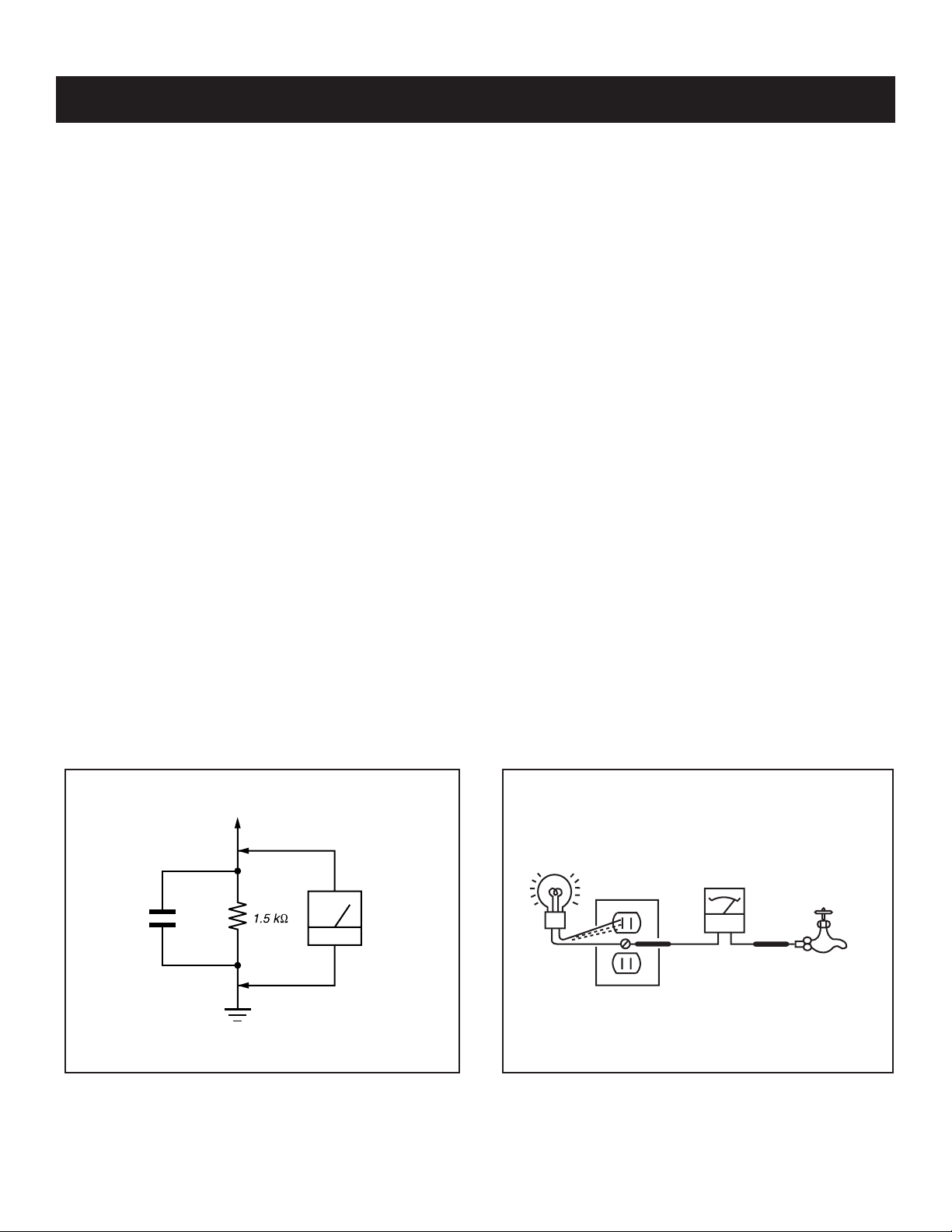
Leakage Test
The AC leakage from any exposed metal part to earth ground and
from all exposed metal parts to any exposed metal part having a
return to chassis, must not exceed 0.5 mA (500 microamperes).
Leakage current can be measured by any one of three methods.
1. A commercial leakage tester, such as the Simpson 229 or RCA
WT-540A. Follow the manufacturers’ instructions to use these
instructions.
2. A battery-operated AC milliampmeter. The Data Precision 245
digital multimeter is suitable for this job.
3. Measuring the voltage drop across a resistor by means of a VOM
or battery-operated AC voltmeter. The “limit” indication is 0.75
V, so analog meters must have an accurate low voltage scale.
The Simpson’s 250 and Sanwa SH-63TRD are examples of
passive VOMs that are suitable. Nearly all battery-operated digital
multimeters that have a 2 VAC range are suitable (see Figure A).
How to Find a Good Earth Ground
A cold-water pipe is a guaranteed earth ground; the cover-plate
retaining screw on most AC outlet boxes is also at earth ground. If the
retaining screw is to be used as your earth ground, verify that it is at
ground by measuring the resistance between it and a cold-water pipe
with an ohmmeter. The reading should be zero ohms.
If a cold-water pipe is not accessible, connect a 60- to 100-watt
trouble- light (not a neon lamp) between the hot side of the receptacle
and the retaining screw. Try both slots, if necessary, to locate the hot
side on the line; the lamp should light at normal brilliance if the screw
is at ground potential (see Figure B).
0.15 µF
Figure A. Using an AC voltmeter to check AC leakage. Figure B. Checking for earth ground.
KDF-E55A20/E60A20
To Exposed Metal
Parts on Set
Earth Ground
AC
Voltmeter
(0.75V)
Trouble Light
AC Outlet Box
Ohmmeter
Cold-water Pipe
7
Page 8

KDF-E55A20/E60A20
p
SELF-DIAGNOSTIC FUNCTION
Self Diagnosis
Supported model
The units in this manual contain a self-diagnostic function. If an error occurs, the POWER/STANDBY or LAMP LED will automatically begin to fl ash.
The number of times the LED fl ashes translates to a probable source of the problem. A defi nition of the POWER/STANDBY or LAMP LED fl ash
indicators is listed in the instruction manual for the user’s knowledge and reference. If an error symptom is diffi cult to reproduced use the Remote
Commander to display the record that is stored at the internal NVM to specify the cause of the failure.
Diagnostic Test Indicators
When an error occurs, the POWER/STANDBY or LAMP LED will fl ash a set number of times to indicate the possible cause of the problem. If there
is more than one error, the LED will identify the fi rst of the problem areas. If the errors occur simultaneously, the one that corresponds to the fewest
fl ashes is identifi ed fi rst.
Results for all of the following diagnostic items are displayed on screen. No error has occurred if the screen displays a “0”.
Diagnostic Item
Description
Lamp cover error 3 times - Lamp cover is not fastened securely. - No picture/No sound
Fan error 4 times
Temp error 4 times
Lamp driver error 5 times - Lamp driver defect - No picture/No sound
Low B error 6 times - No "DD 6V " output (GM board) - No picture/No sound
Audio error 7 times
D-OVP error 8 times
ATSC-OVP error 10 times - No "Q5V " output (GM board, GI board) - No picture/No sound
Lamp error LAMP-LED is ON. - Lamp is dead - No picture/No sound
Number of times
STANDBY or
LAMP LED lam
Probable Cause Detected Symptoms
- Fan1-4 Power is not supplied.
(GI board)
- Fan connector is not seated securely.
- Fan caught wires or harnesses.
- Internal temperature is too high.
- IIC-E line connector(H4 board)
is not seated properly.
- Short-circuit of Audio power supply line
(KD board, GM board)
- Blowout of a fuse
(PS4702,PS4703 on KD board)
- IC failure
(IC4703,IC4708,IC4710 on KD board)
- Overvoltage of +3.3V or +2.5V
(A board, B board)
- No picture/No sound
- No picture/No sound
- No picture/No sound
- No picture/No sound
KDF-E55A20/E60A20
8
Page 9
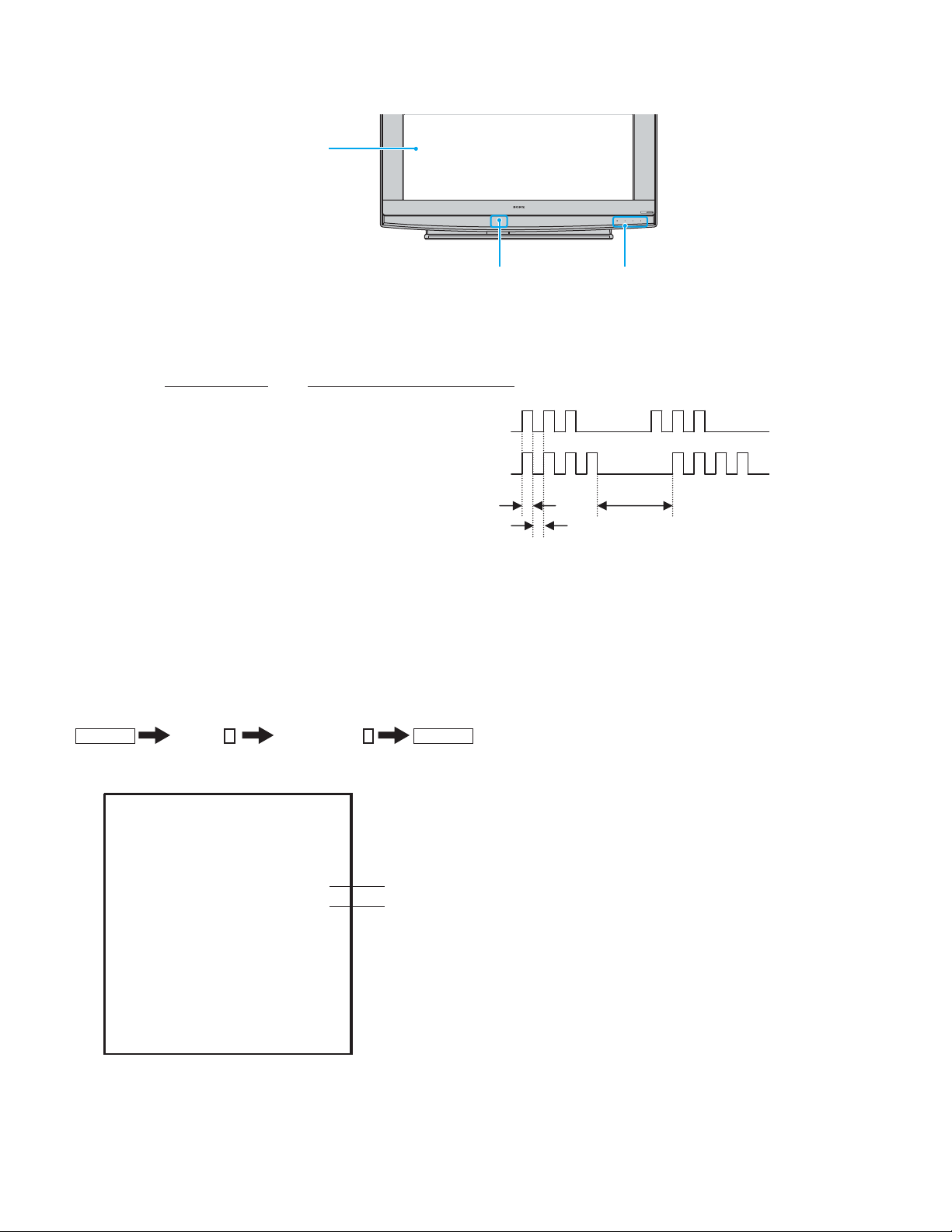
Display of POWER/STANDBY or LAMP LED Flash Count
Screen
LAMP TIMER POWER
KDF-E55A20/E60A20
POWER
Projection lamp
Indicators
- Oneflashis notusedfor self-diagnosis.
-Example
Diagnosis
Number of times LED Flash
Lampcover 3 times
Fan 4 times
LED ON: 0.3sec
LED OFF : 0.3sec
LED OFF
3.0sec
Releasing the POWER/STANDBY LED Flash
Unplug the power cord from the outlet to temporarily stop the POWER/STANDBY lamp from fl ashing.
Self-Diagnosis Screen Display
For failures that are diffi cult to reproduce, or accompany occasional power off and/or picture mute, the Self-Diagnosis screen display is useful to
specify the cause..
To Bring Up Screen Test
In standby mode, press the buttons on the Remote Commander sequentially, in rapid succession, as shown below:
DISPLAY
1.
Self-Diagnostic Screen Display
Channel
5
Sound Volume -
POWER
SELFCHECK
1 : LAMP ERR 0
3:
LAMP COVER 0
FAN-E/TEMP-E 1
4:
5 : LAMP DRIVER
0
"1" is displayed when a failure is detected one or more times
"0" is displayed when no failure has been detected
6 : LowB-ERR 0
7 : Audio-Prot
1
8 : D-OVP 0
10 : ATSC_OVP 0
101 : WDT 0
Since the diagnostic results displayed on the screen are not automatically cleared, always check the self-diagnostic screen during repairs. When you
have completed the repairs, clear the result display to “0”.
Note: The self-diagnostic function will not be able to detect any subsequent faults after completion of the repairs unless the result display is
cleared to “0”.
KDF-E55A20/E60A20
9
Page 10
KDF-E55A20/E60A20
Clearing the Result Display
To clear the result display to “0”, press the buttons on the Remote Commander sequentially when the diagnostic screen is displayed, as shown below:
1. If the screen is already displayed, proceed to step 3. If not, Power off (Set to Standby mode).
2. Press
DISPLAY
Channel
3. Press Channel 8
ENT
5
Sound Volume -
Clearing the Self-Diagnostic Screen
The self diagnosis screen display is cleared by turning off the set using the Remote Commander or the power switch.
Self-Diagnostic Circuit
Self-Diagnosis Function Operation
3 : Lamp cover The rib at the back of the lamp cover closes the SW on the T board to ground pin 3 of CN8001.
It is monitored by the DE-micro (pin 94 of IC6902) and turns off the lamp when it is opened.
4 : Fan Fan rotation is detected by "FAN-PROT" and the DE-micro (pin 92 of IC6902) turns off the lamp
when it is "high".
4 : Temp When the temperature sensor on the H4 board detects high temperature, or IIC-E line connector
(CN6022:GI board, CN44:H3board/H4board) is not seated securely, the DE-micro turns off the
lamp.
5 : Lamp driver When the "LAMP-PROT" (pin 95 IC6902) is low, the lamp is not turned on. If the "LAMP-HV-
DET" (pin 96 IC6902) is low at the same time, it is classified as no high voltage of the lamp
6 : Low B error When no "SETIIV " is detected, pin 129 of IC3002 is low and it turns off the main power.
driver.
7 : Audio When DC voltage is detected at the speaker or woofer outputs, pin 128 of IC3002 is low and it
turns off the main power.
8 : D-OVP When overvoltage of "+3.3V" or "+2.5V" is detected, pin 126 of IC3002 is low and it turns off the
10 : DTL-OVP When no "Q 5V" is detected, pin 127 of IC3002 is low and it turns off the main power.
main power.
LAMP : Lamp When the "LAMP-PROT" (pin 95 IC6902) is low, the lamp is not turned on. If the
"LAMP-HV-DET" (pin96 IC6902) is high at the same time, it is classified as no lamp or a dead
lamp.
POWER
KDF-E55A20/E60A20
10
Page 11
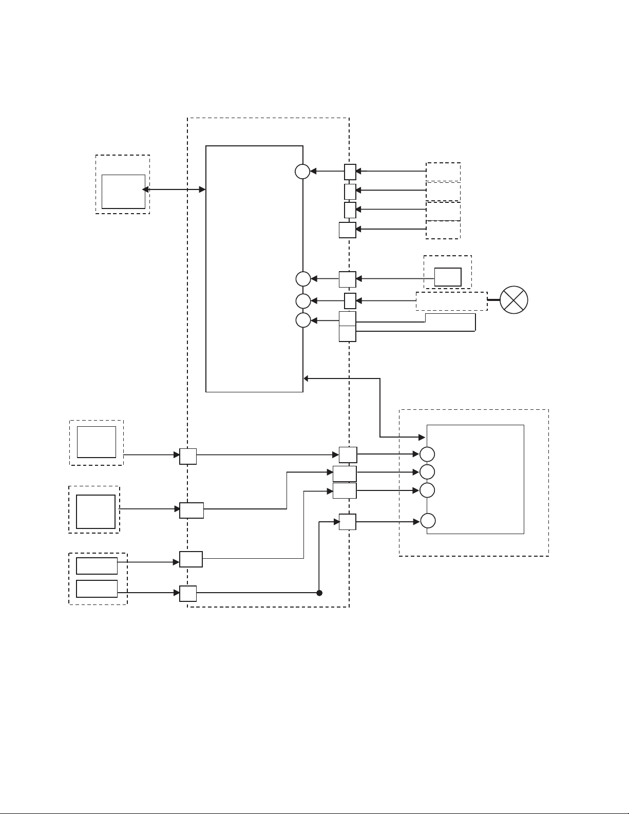
Self-Diagnosis Block Diagram
(SN 9,000,001 to 9,099,999 and 9,800,001 to 9,899,999 Only)
GI board
IC6902
H4 board
IC41
Te m p
4:Temp
Display Engine u-com
FAN PROT
IIC-E
4:Fan
92
sensor
LAMP-COVER
LAMP-PROT
LAMP-HV-DET
94
95
96
CN6000
2
5
8
11
CN6022
14
8
13
14
FAN1-PRT
FAN2-PRT
FAN3-PRT
FAN4-PRT
3:Lamp cover
5:Lamp
driver
Fan1
Fan2
Fan3
Fan4
T board
S8001
SW
Lamp driver
HV-DET
KDF-E55A20/E60A20
Lamp
KD board
Audio
amp
GM board
+3.3V
+2.5V
GM board
SETIIV
Q5V
7:Audio
8:D-OVP
6:LowB
error
CN6029
23
CN1609
A14
CN1609
B14
CN6006
5
IIC-TV
CN6019
A8
A14
B14
CN6017
16
12:DTL
OVP
B1 board
IC3002 TV u-com
IIC-TV
SP_DC_PROT
128
126
D_OVP
LB_ERROR
129
127
ATSC_OVP
KDF-E55A20/E60A20
11
Page 12
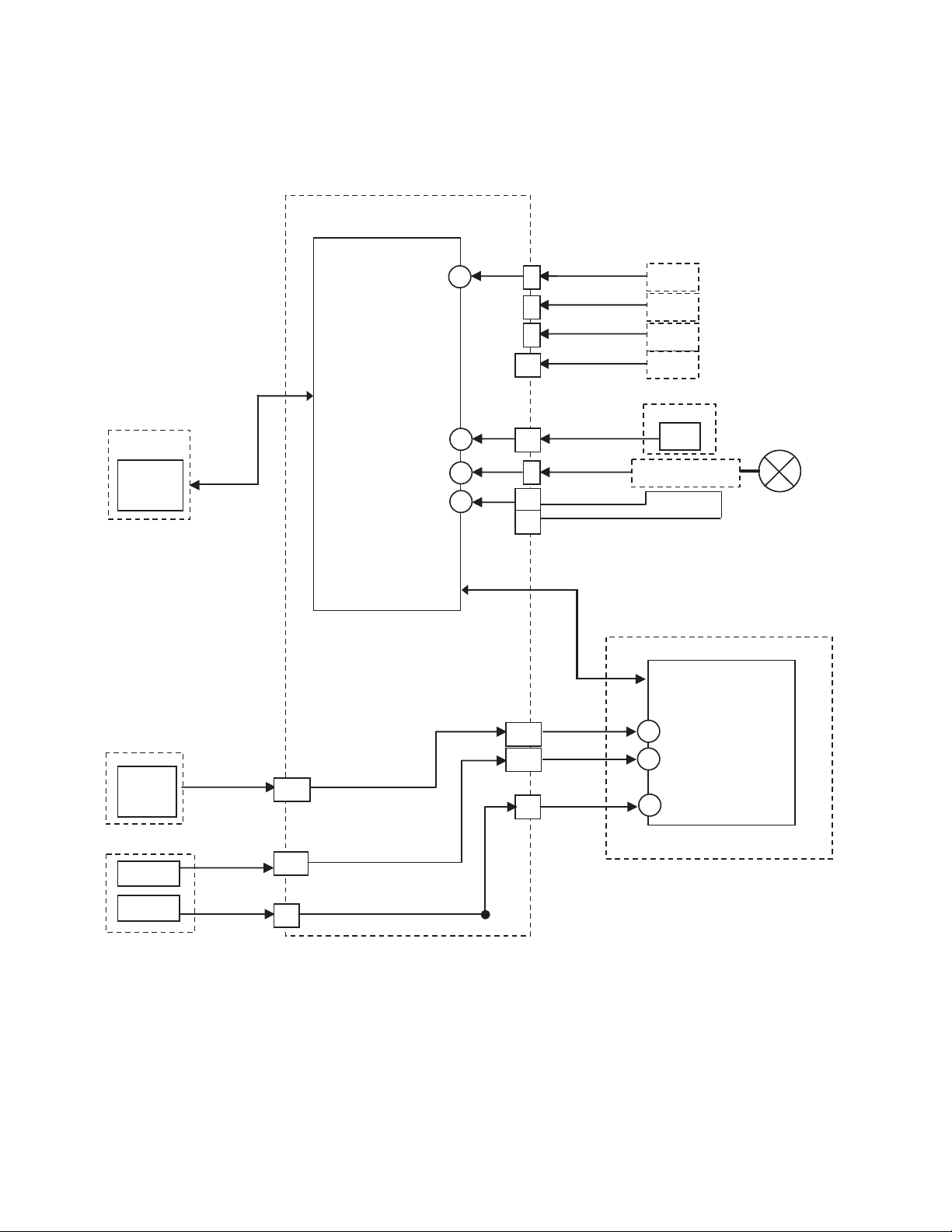
Self-Diagnosis Block Diagram
(SN 9,100,001 to 9,799,999 and 9,900,001 and Up Only)
GK board
IC6902
Display Engine u-com
92
94
95
96
IC6911
Te m p
sensor
FAN PROT
IIC-E
LAMP-COVER
LAMP-PROT
LAMP-HV-DET
4:Fan
CN6022
CN6000
2
5
8
11
14
8
13
14
FAN1-PRT
FAN2-PRT
FAN3-PRT
FAN4-PRT
3:Lamp cover
5:Lamp
driver
Fan1
Fan2
Fan3
Fan4
T board
S8001
SW
Lamp driver
HV-DET
KDF-E55A20/E60A20
Lamp
GM board
+3.3V
+2.5V
GM board
SETIIV
Q5V
8:D-OVP
6:LowB
error
CN1609
A14
CN1609
B14
CN6006
5
IIC-TV
A14
B14
CN6017
16
12:DTL
OVP
B1 board
IC3002 TV u-com
IIC-TV
126
D_OVP
LB_ERROR
129
127
ATSC_OVP
KDF-E55A20/E60A20
12
Page 13
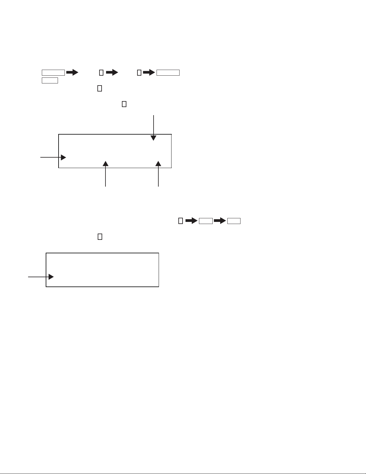
Reading Lamp and Panel time
Use the following to determine the lamp and panel time of a set.
Screen Display Method
To access service mode, press the buttons on the Remote Commander sequentially, in rapid succession, as shown below:
KDF-E55A20/E60A20
1. Press
2. Press
3. To display the Lamp time, press 2 until the OPTION_E category displays.
4. The LampTM is the fi rst item in the OPTION_E category.
(If the LampTM item is not displayed, press 1 until the LampTM item displays.)
DISPLAY
JUMP
Channel
until the PANEL service menu displays.
5
Volume +
POWER
Category
exam
ple
PANEL NVM OK 9 OPTION_E
0 LAMP 0 Diff 1
Item
The screen displays:
“Total lamp time is 14 hours” and “Total lamp ON/OFF cycle is 71 times”
NOTE: If replacing the lamp, reset the lamp time by pressing Channel
WRI-EXE(Character color is Red) is momentarily displayed and LampTM is reset to “0”.
5. To display the Panel time, press 1 until the PanelTM item displays.
LampTM LampCT14 71
Hours On/Off Cycle
3
Mute
ENT
.
example
PANEL NVM OK 9 OPTION_E
7 SH SFT1 10 Diff 1
PanelTM 14h
The screen displays:
“Total Panel time is 14 hours”
NOTE: You cannot reset the Panel time with the Service menu.
Exiting Service Mode
After completing the changes exit service mode by turning off the set using the Remote Commander or the power switch.
KDF-E55A20/E60A20
13
Page 14
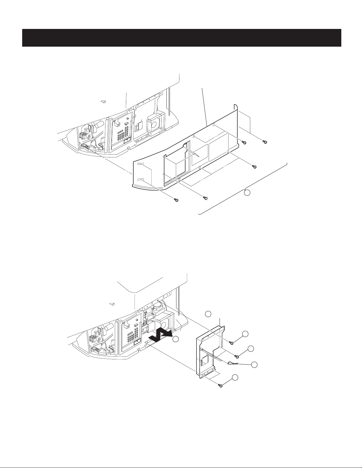
1-1. REAR COVER REMOVAL
KDF-E55A20/E60A20
SECTION 1: DISASSEMBLY
Rear cover
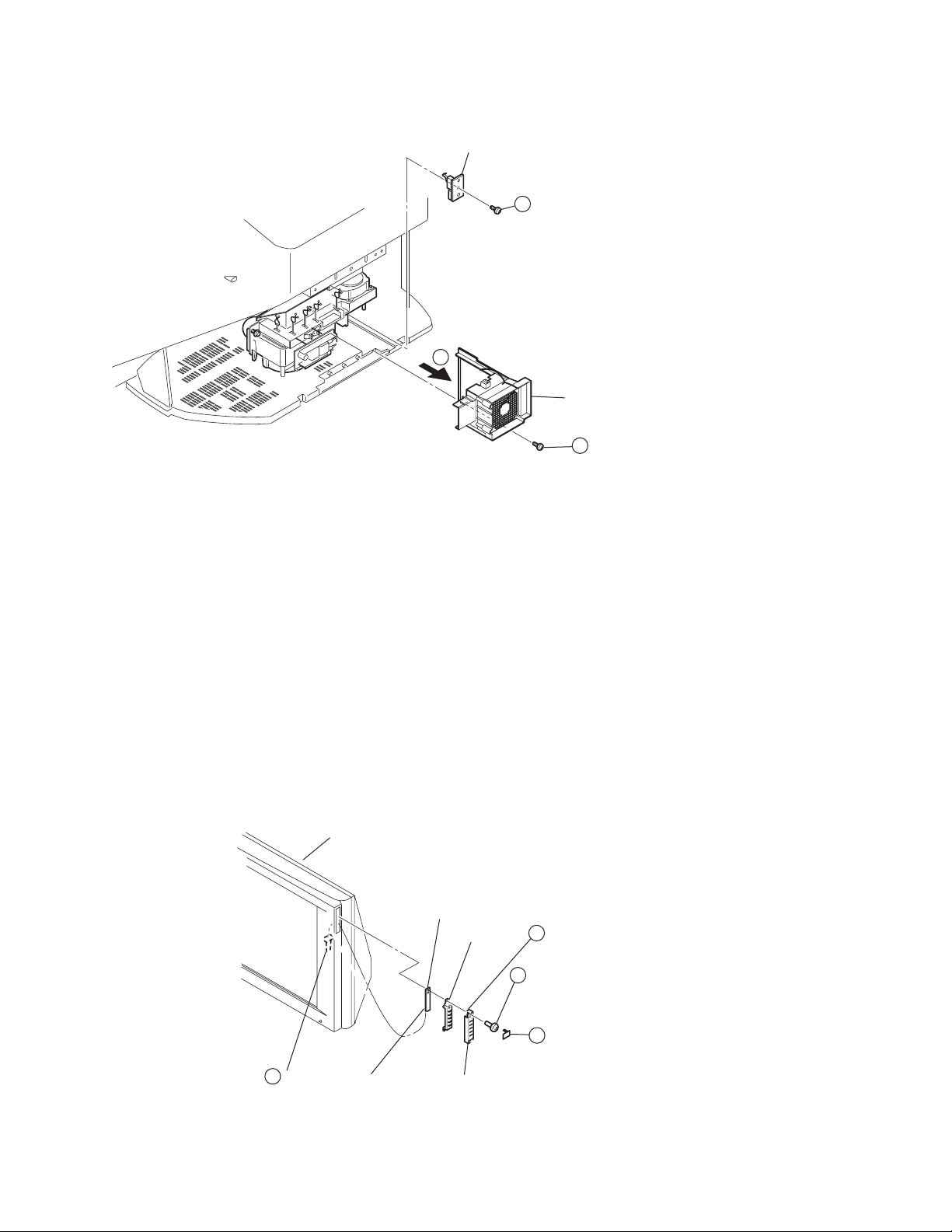
1-2. OU BRACKET REMOVAL
1
Thirteen screws
(+BVTP 4x16)
OU bracket
6
One Screw
4
1
(+BVTP 4x16)
2
Two screws
(+BVTP 4x16)
5
Three ground wires
KDF-E55A20/E60A20
3
Two screws
(+BVTP 4x16)
14
Page 15
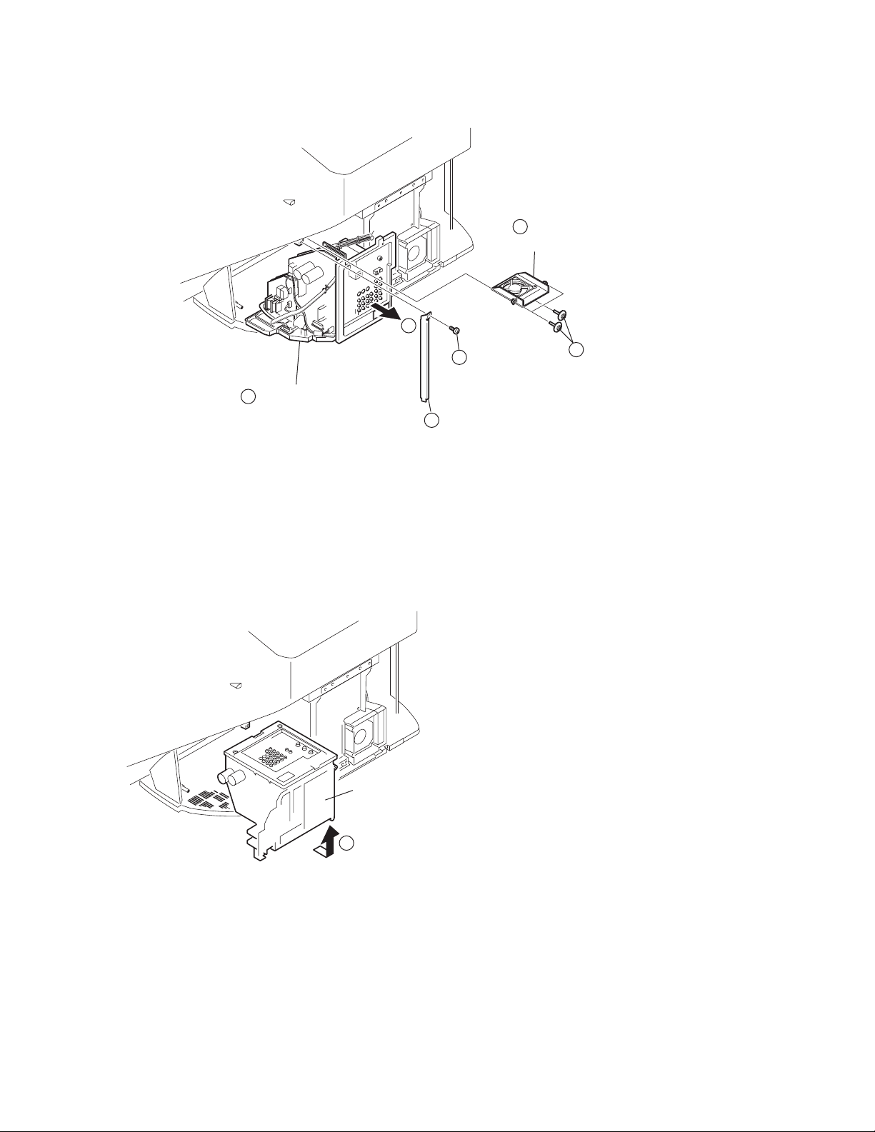
1-3. CHASSIS ASSEMBLY AND FAN REMOVAL
3
Chassis assembly
4
1
Screw
(+BVTP 4x16)
Side stay (R)
2
Fan bracket (chassis)
6
with DC fan
5
Three screws
(+PTPWH 4x16)
KDF-E55A20/E60A20
1-4. SERVICE POSITION
Chassis assembly
Pull back on claw, then gently pull out chassis assembly
1
KDF-E55A20/E60A20
15
Page 16
1-5. RF ANTENNA SWITCH REMOVAL
KDF-E55A20/E60A20
Unplug five connectors
4
Four Screws (+BVTP 3x12)
2
U bracket
Push down on tab to release bracket
3
5
RF antenna switch
Two Washers
1
Three Screws (M3x8) P, SW(+)
2
1-6. U1 BOARD AND H4 BOARD REMOVAL
The H4 Board is only in SN 9,000,001 to 9,099,999 and 9,800,001 to 9,899,999
Gently pull back on tab to
release U1 board
One screw
(+BVTP 3X12)
2
3
Gently pull back on tabs
to release H4 board
1
U1 board
KDF-E55A20/E60A20
16
Page 17
1-7. GM BOARD REMOVAL
KDF-E55A20/E60A20
Disconnect three connectors
(CN1611, CN1608 & CN1612)
Disconnect three ground wires
(CN1603, CN1604 and CN1605)
2
Claw
6
GM board
1
Disconnect the Power cord
from CN1602 connector.
4
8
9
Gently pull back on the three clips
on the pin connection slots
while slowly lifting the GM board.
5
Remove wires from purse locks
Unfasten two Circuit Board Supports
1-8. A1 BOARD (OR A2 BOARD) AND KD BOARD REMOVAL
The A1 Board and the KD Board are only in SN 9,000,001 to 9,099,999 and 9,800,001 to 9,899,999
The A2 Board is only in SN 9,100,001 to 9,799,999 and 9,900,001 and up
Disconnect two connectors
(CN4705 and CN4702)
Unfasten two Circuit Board Supports
Disconnect two connectors
(CN8003 and CN8008)
and coax cable from tuner
Gently pull back
on the three clips
on the Pin Connection slots
while slowly lifting the A board
Remove cables
from purse locks
4
3
1
6
2
A1 board
KD board
Gently pull back
5
on the two clips
on the Pin Connection slots
while slowly lifting the KD board
KDF-E55A20/E60A20
17
Page 18

1-9. DMB ASSEMBLY (Q BOX) AND B1 BOARD REMOVAL
KDF-E55A20/E60A20
Disconnect two connectors
and one ground wire
Unplug two coax cables
connected to the antenna switch
Remove four screws
(+BVTP 3X12)
6
Remove two screws
5
(+BVTP 3X12 TYPE2)
7
DMB Box Assembly
Remove one screw
3
9
(3X12), + BVWHTP
Remove two connectors
2
(CN3500 and CN3501)
1
Remove cables from purse locks
B1 board
Gently pull back
4
on the two clips
on the Pin Connection slots
while slowly lifting the B1 board
1-10. GI BOARD (OR GK BOARD) REMOVAL
The GI Board is only in SN 9,000,001 to 9,099,999 and 9,800,001 to 9,899,999
The GK Board is only in SN 9,100,001 to 9,799,999 and 9,900,001 and up
Disconnect 5 connectors
(CN6000, CN6028,
CN6021, CN6023,
and CN6022)
Disconnect 1 ground wire
(CN6018)
Gently pull back on the two clips
while slowly lifting the GI Board.
1
3
2
GI board
4
KDF-E55A20/E60A20
18
Page 19
1-11. FAN AND T BOARD REMOVAL
2
T board
Screw
3
(+BVTP 3x12)
Duct fan bracket
with DC fan
1
KDF-E55A20/E60A20
Screw
(+BVTP 4x16)
1-12. H1 BOARD REMOVAL
Disconnect one connector
KDF-E55A20/E60A20
3
Screen mirror block assembly
H1 board
H1 button
H1 board
H1 bracket
Gently pull back on the bottom tab
4
of the H1 bracket then slide out the H1 board
One screw
2
(+BVTP 3X12)
1
Using tweezers gently detach the
H1 Bracket Cap
19
Page 20
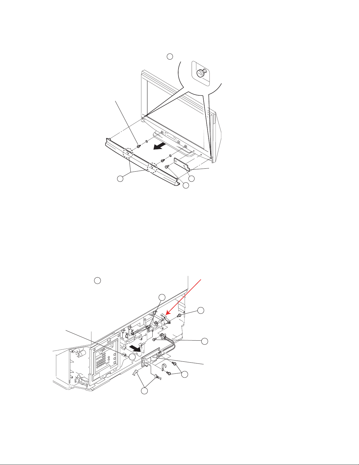
1-13. FRONT COVER ASSEMBLY REMOVAL
Be sure the Front Input door is closed before removing the Front Cover Assembly.
Two screws
(+BVTP 3X12 TYPE2)
KDF-E55A20/E60A20
1 Remove the two ornamental screws from back of set
Cable Cover
Gently pull the
Front cover assembly forward.
Note the area of the 2 magnets
holding the cover
2
4
Push towards center of set to unlatch
3
One screw
(+BVTP 3X12)
1-13-1. REPLACING THE LAMP
For detailed instructions on replacing the lamp, see Page 76 of the Operating Instructions manual.
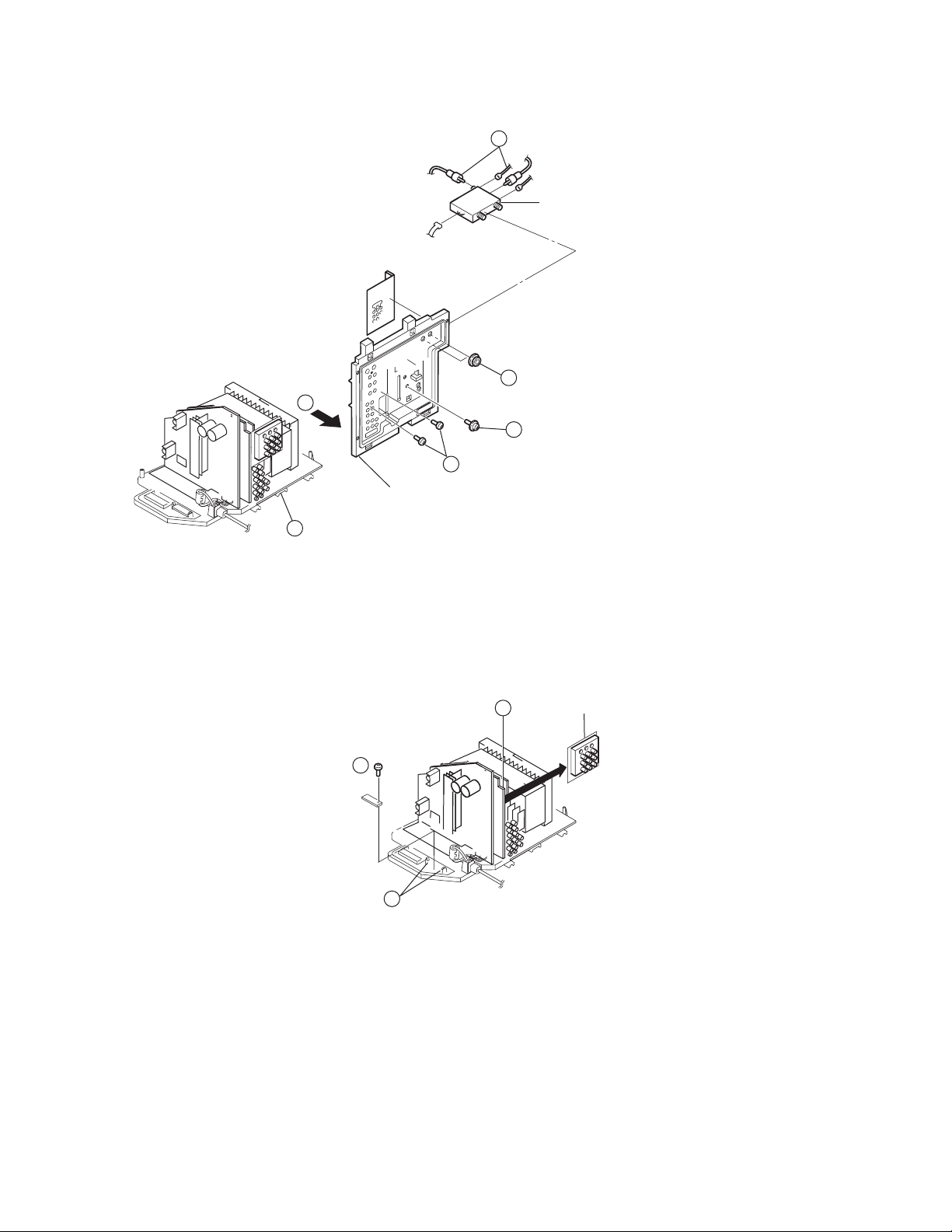
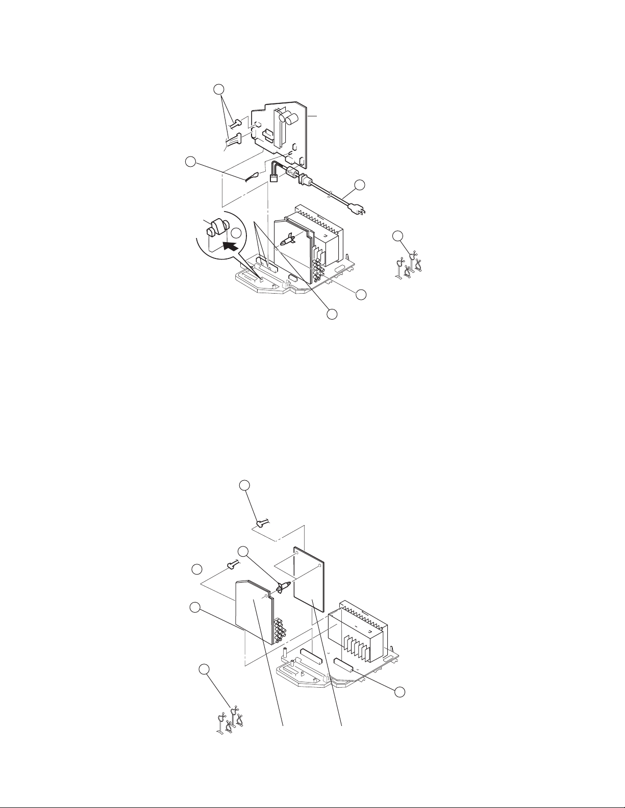
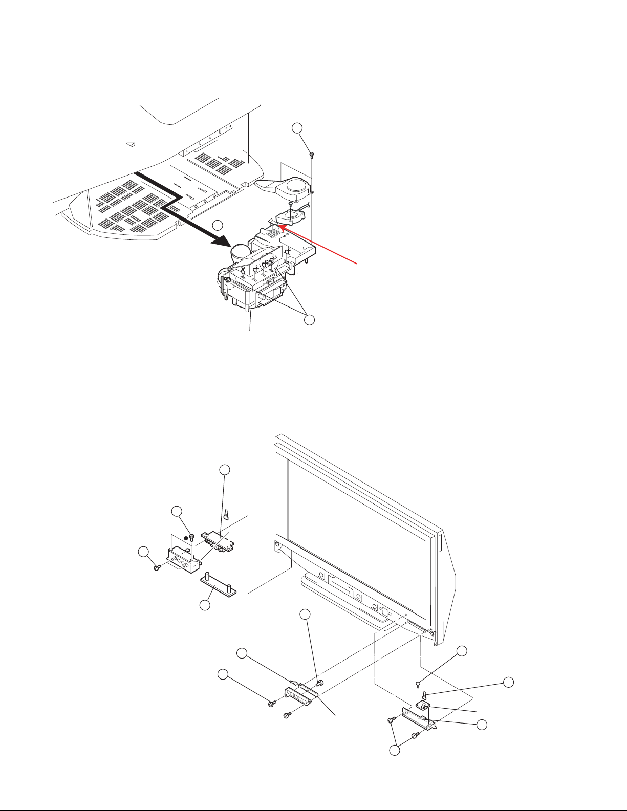
1-14. POWER SUPPLY BLOCK REMOVAL (LAMP DRIVE UNIT)
Use caution when removing the Power Supply Block to not move the Optical Unit Block
NOTE: Do not discard the Plug Holder Assembly
when replacing the Power Supply block.
This part is not included with the
Power Supply assembly.
One screw (+PWH 4x16)
3
(to detach the Plug Holder Assembly from the
Lamp Bracket)
4
Two screws (+PWH 4x16)
(to release the cables from the bracket)
Power supply block
Four screws (+BVTP 3x12)
Pull forward to remove
1
Remove the lamp
Unhook the antenna cable
7
5
6
KDF-E55A20/E60A20
2
Disconnect two connectors
20
Page 21
1-15. OPTICS UNIT BLOCK ASSEMBLY FAN REMOVAL
Remove three screws
3
(+BVTP 3X12)
2
1
Two screws
Optics Unit block assembly
(with power supply block)
KDF-E55A20/E60A20
NOTE: Do not discard the Plug Holder Assembly
when replacing the Optics Unit block assembly.
This part is not included with the
Optics Unit block assembly.
1-16. H2 BOARD, H3 BOARD, AND H5 BOARD REMOVAL
10
11
One screw
(+BVTP 3x12)
2
1
3
H2 board
disconnect one connector
Two screws
(+BVTP 3X12 TYPE2)
Push H3 Door
open to remove
Two screws
(+BVTP 3X12 TYPE2)
Remove H3 Bracket (R)
Disconnect one connector
(CN4502)
Push H3 Board back
to release and
9
8
Two screws
(+BVTP 3X12 TYPE2)
Remove two screws
5
(+BVTP 3X10)
Disconnect
6
one connector
H5 board
7
(CN7301)
Lift the H5 board up
KDF-E55A20/E60A20
4
Two screws
(+BVTP 3X12 TYPE2)
21
Page 22
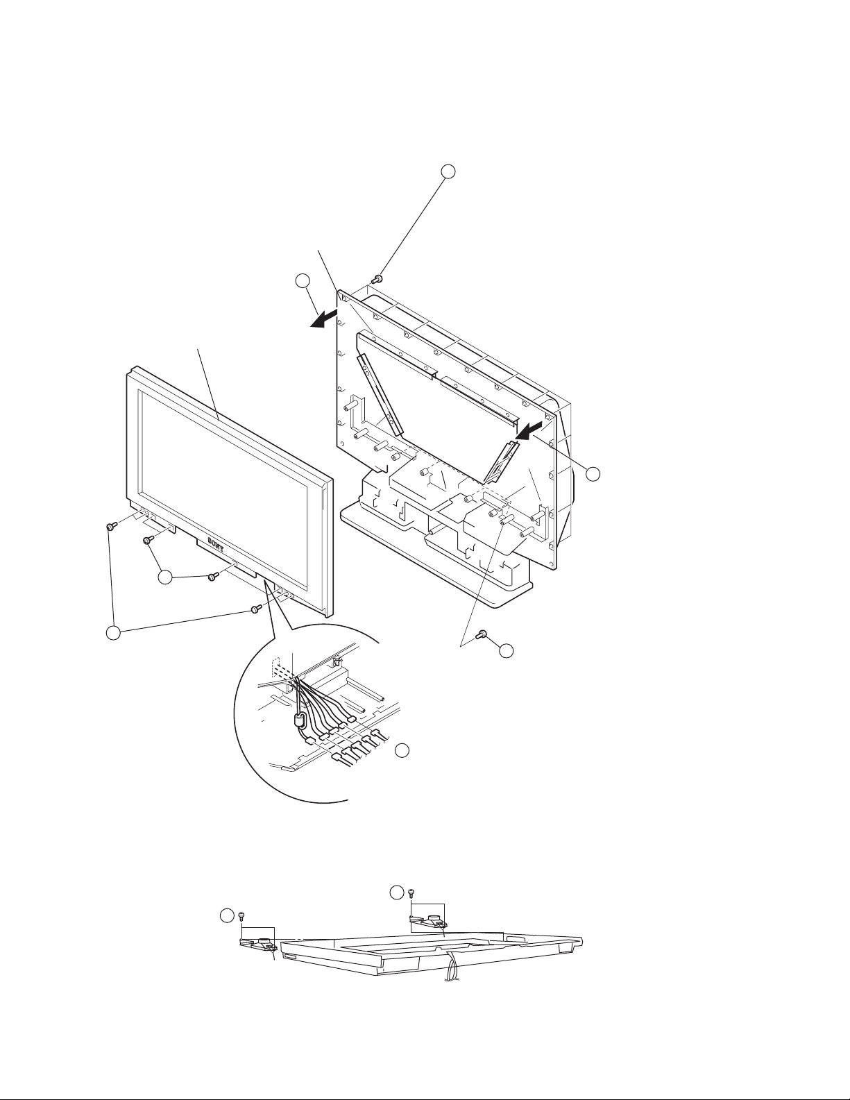
1-17. SCREEN MIRROR BLOCK ASSEMBLY REMOVAL
Caution:
When repairing anything inside the Screen Mirror Block Assembly be sure to clean the mirror and Diffusion Plate(s)
to remove any dust particles.
Remove sixteen screws
5
(+BVTP 4X16)
TIP: The Mirror Cover assembly is securely fasten
to the Screen Frame assembly. To ease removal,
Mirror Cover assembly
Pull left side of
Screen Frame assembly
away from Mirror Cover assembly
Screen Frame assembly
6
leave screws to secure the top right side of the
Screen Frame while pulling the left side of the screen
away from the Mirror Cover. Replace the Screen Frame,
then remove the last two screws, then while securing
the left side of the Screen Frame with your hand,
pull the right side of the Screen Frame away
from the Mirror Cover.
KDF-E55A20/E60A20
4
Four screws
(+BVTP 4x16)
3
Four screws
(+BVTP 4x16)
1-18. SPEAKER REMOVAL
2
Remove four screws
(+BVTP 4X16)
1
Remove chassis and large fan
from the inside the Rear Cover to
disconnect five connectors
7
Pull right side of
Screen Frame assembly
away from
Mirror Cover assembly
Two screws
(WASHER HEAD)
(+P 4X16)
KDF-E55A20/E60A20
1
1
22
Page 23

WIRE DRESSING
Use these instructions for SN 9,000,001 to 9,099,999 and 9,800,001 to 9,899,999
for SN 9,100,001 to 9,799,999 and 9,900,001 and up use instructions on Page 34
[KD] Shield to QU Heat Sink
KDF-E55A20/E60A20
[C] LVDS Connector
Route LVDS Connector as shown below
[B1] LVDS
231876601
ELECTRIC CONDUCTION TAPE, A
(1 Piece)
Install Faston Terminal of
191001690 to DMB. Route
wire around Main Harness
and LVDS
DMB PP Cable
DMB LVDS AND [B1] LVDS
191001690
WIRE ASSY, FASTON TERMINAL
Secure w/ B1 Shield Screw
KDF-E55A20/E60A20
ELECTRIC CONDUCTION TAPE, A
231876601
(2 Pieces)
Tape Must completely cover connector header and
make good contact with shield
23
Page 24
231876601
ELECTRIC CONDUCTION TAPE, A
(1 Piece)
KDF-E55A20/E60A20
KDF-E55A20/E60A20
Do Not Crease/Fold FFC cable
After securing the coax cable on DMB ensure that it is in a
horizontal position as shown below
24
Page 25
191001689
WIRE ASSY, FASTON TERMINAL
KDF-E55A20/E60A20
Dress into B1 Clamp
Install to CN6018 on [GI]
KDF-E55A20/E60A20
Ground from
GM Board
Ground from
GI Board
Dress into 2nd B1 Clamp
25
Page 26
Single Braided Wire
to OU Bracket
Double Braided Wire
to ANT SWITCH
191001691
WIRE ASSY, FASTON TERMINAL
KDF-E55A20/E60A20
Dress into U-Bracket
Dress Under Ant Switch
KDF-E55A20/E60A20
Install Double
Braided Wire into
Ant Switch
Ground from
GM Board
Ground from
GI Board
26
Page 27
404928101
PURSE LOCK (DIA.11)
146908911
FILTER, CLAMP (FERRITE CORE)
KDF-E55A20/E60A20
146908911
FILTER, CLAMP (FERRITE CORE)
Install on COAX cable.
Ferrite core MUST be between B1 Shield and DMB Shield
FILTER,CLAMP
(FERRITE CORE)
KDF-E55A20/E60A20
404928101
PURSE LOCK (DIA.11)
150049711
Excess Cable should be
placed inside opening
404928101
PURSE LOCK (DIA.11)
404928101
PURSE LOCK (DIA.11)
150049711
FILTER,CLAMP(FERRITE CORE)
Loop Video 2 around core 1 time
27
Page 28
PURSE LOCK (DIA.11)
H3 Connector Assy, Speaker/Power
Button/Control Button Connector
Assys Secure with Purse Lock to
Main Harness as shown
KDF-E55A20/E60A20
404928101
150008211
CLAMP, SLEEVE FERRITE
Loop Connector Around Ferrite one
time
KDF-E55A20/E60A20
150008211
CLAMP, SLEEVE FERRITE
28
Page 29

1. Install 4-662-796-01 CLIP, COACHING to
H4 Board.
2. Then secure using 7-685-648-71 SCREW
+BVTP 3X12 TYPE2 IT-3
1. Install AC Cord to CN1602 on [GM] Board
KDF-E55A20/E60A20
KDF-E55A20/E60A20
29
Page 30

1. Twist AC Cord as shown and install into
Chassis bracket.
1. Secure AC cord with Clip, Coaching as shown
KDF-E55A20/E60A20
KDF-E55A20/E60A20
30
Page 31

HM BLOCK WIRE DRESSING
Secure H5 Connector Assy with
Sony P/N 407859001 TAPE
KDF-E55A20/E60A20
KDF-E55A20/E60A20
Tape should not overlap bottom
edge of HM BRACKET
Bottom Edge
31
Page 32

KDF-E55A20/E60A20
Install on B1 Board as Shown
Install on C Board as Shown
Add Tape as shown in PCN MB606921
Dress LVDS and Optical
Block Fan Connector to Clip
on C Board
Dress LVDS Connector to B1
Shield Clips as shown
KDF-E55A20/E60A20
Add Tape as shown in PCN MB606921
32
Page 33

KDF-E55A20/E60A20
Dress LVDS Connector to
Purselock on top of B1 w/ Main
Harness
Dress LVDS Connector to "1st"
Purselock on C Board
Dress LVDS Connector
to Clip on C Board
LVDS CONNECTOR WILL CHANGE FROM SONY P/N 1-910-004-95 to 1-830-099-41
SEE RN ECB03799 AND PCN MB607037
KDF-E55A20/E60A20
33
Page 34

Use these instructions for SN 9,100,001 to 9,799,999 and 9,900,001 and up
CN6023 DMB CONN ASSY
WIRE DRESSING
146908911
FILTER, CLAMP (FERRITE CORE)
Dress in
Purselock As
shown
KDF-E55A20/E60A20
CLAMP, SLEEVE FERRITE
KDF-E55A20/E60A20
150008211
CLAMP, SLEEVE FERRITE
150008211
34
Page 35

KDF-E55A20/E60A20
Dress into
Purselock on B1
Block
Main Harness Wire Dress
1. Install CN1608 on [GM]
2. Install CN1612 on [GM]
KDF-E55A20/E60A20
3. Dress to Purselock as shown
Note: CN1608 is not in purselock.
Connect Main Harness to GK board as
shown
35
Page 36

Main Harness Wire Dress
(continued)
KDF-E55A20/E60A20
LEFT HAND SIDE OF MAIN HARNESS
RIGHT HAND SIDE OF MAIN HARNESS
1-910-016-90 WIRE ASSY, FASTON TERMINAL SHOULD GO
KDF-E55A20/E60A20
.
AROUND MAIN HARNESS AND DMB CONNECTOR
Install CN6601 on GK Board
36
Page 37

Conductive Tape Application
Route LVDS Connector as shown below
[B1] LVDS
KDF-E55A20/E60A20
DMB PP Cable
231876601
ELECTRIC CONDUCTION TAPE, A
(1 Piece)
KDF-E55A20/E60A20
[C] LVDS Connector
DMB LVDS AND [B1] LVDS
231876601
ELECTRIC CONDUCTION TAPE, A
(2 Pieces)
Tape Must completely cover connector header and
make good contact with shield
37
Page 38

231876601
ELECTRIC CONDUCTION TAPE, A
(1 Piece)
KDF-E55A20/E60A20
Ferrite core MUST be between B1 Shield and DMB Shield
KDF-E55A20/E60A20
146908911
FILTER, CLAMP (FERRITE CORE)
Install on COAX cable.
After securing the coax cable on DMB ensure that it is in a
horizontal position as shown below
38
Page 39

KDF-E55A20/E60A20
Single Braided Wire
to OU Bracket
Double Braided Wire
to ANT SWITCH
Install Double
Braided Wire into
Ant Switch
191001691
WIRE ASSY, FASTON TERMINAL
Dress into U-Bracket
Dress Under Ant Switch
Ground from
GM Board
KDF-E55A20/E60A20
Ground from
GI Board
39
Page 40

191001689
WIRE ASSY, FASTON TERMINAL
KDF-E55A20/E60A20
Dress into B1 Clamp
Install to CN6018 on [GI]
KDF-E55A20/E60A20
Ground from
GM Board
Ground from
GI Board
Dress into 2nd B1 Clamp
40
Page 41

KDF-E55A20/E60A20
404928101
PURSE LOCK (DIA.11)
150049711
FILTER,CLAMP
(FERRITE CORE)
150049711
FILTER,CLAMP (FERRITE CORE)
Video 2 Harness ONLY
If There is Excess Cable
Secure with Purse Lock As shown
Below
404928101
PURSE LOCK (DIA.11)
Dress Fan Connector to Clip on
[C] Block
PURSE LOCK (DIA.11)
KDF-E55A20/E60A20
404928101
150008211
CLAMP, SLEEVE FERRITE
Loop Connector Around Ferrite one
time
41
Page 42

Dress Connector Assy to wire Pin
on [A2] board as shown
To keep from touching IC6400
HEATSINK
KDF-E55A20/E60A20
KDF-E55A20/E60A20
Install CN8003 on [A2]
42
Page 43

A
SECTION 2: CIRCUIT ADJUSTMENTS
KDF-E55A20/E60A20
2-1. REMOTE ADJUSTMENT BUTTONS AND
INDICATORS
2-2. ACCESSING THE SERVICE
ADJUSTMENT MODE
To adjust various set features, use the Remote Commander to put the set
POWER
Increase
3
Data value
Next
djustment
MUTING
Write into
memory
1
MUTING
DVR
TV/VIDEO
DVD/
VCR
POWER
SAT/
CABLE
TV POWER
TV
Item
Decrease
Next
2
Category
Previous
Adjustment
Item
JUMP
Displays
JUMP ANT MTS/SAP
4
SOUND PICTURE
G EDIU
TV/SAT
SUR
ENT
ID PS
FREEZE
WIDE
YAL
Service Menus
8
Restore User Control
and Channel Memory
NRUTER
PREV
VISUAL SEARCH
VOL
WAGE
REPLAY
PAUS E
SLOOT
ET
AG
NEXT
ADVANCE
PLAY
STOP
CH
6
Data value
Previous
5
Category
ENT
0
Read data
from last
saved NVM
DISPLAY
into service mode to display the service menus.
1. TV must be in standby mode. (Power off).
2. Press the following buttons on the Remote Commander within a
second of each other:
DISPLAY
Channel 5 Volume +
POWER
.
The fi rst service menu (TV) displays.
3. To display the service menu that contains the category you want to
adjust, press
JUMP
on the Remote Commander.
(Refer to Service Menus)
Category
Data Value
Item #
VERSION 0 0
VERS
SERVICE
VIDEO 1WIDE ZOOM
480IWSL: 12
VOLUME (+)
REC PAUSE
REC
TOP MENU
MENU
POWER SAVING
RM-YD002
F1
REC STOP
F2
F/A: 000000000 000000000
CBA: 000000000 000000000
Item
Sample TV Service Menu
2-3. CHANGING SERVICE ADJUSTMENT
MODE MEMORY
TV
1. Access Service Adjustment Mode and select the service menu you
want to adjust.
2. To change the category, press 2 or 5 on the Remote Commander.
Note: Pressing 2 or 5 only changes the categories within the service
menu displayed. To change a category on one of the other service
menus, press the
JUMP
button until the correct service menu is
displayed.
3. To change the adjustment item, press 1 or 4 on the Remote
Commander.
4. To change the data value, press 3 or 6 on the Remote Commander.
Note: To go back to the last saved data value, press 0 then
ENTER
on the Remote Commander to read the memory.
5. To write into memory, press
MUTING
then
ENT
on the Remote
Commander.
6. To exit service mode, turn the power off.
KDF-E55A20/E60A20
43
Page 44

KDF-E55A20/E60A20
TV
VERSION
ID
OSD
CCD
CCT
OPTIONS
AP
CXA2229Q
USER_NR
LPF_1
LPF_2
SERVICE MENUS
(CATEGORIES ONLY)
DMB
ASSEMBLY
QM
QT
PANE L
OP
A7001R
A7001G
A7001B
GB_RGB
FAN_CNT1
FAN_CNT2
TEMP
OSD_E
OPTION_E
S_MAS_M
2-4. MEMORY WRITE CONFIRMATION
METHOD
1. After completing all adjustments turn the set off with the Remote
Commander and WAIT for the fans to turn off before proceeding to
the next step.
Note: It may take up to two minutes for the fans to stop.
Caution: To avoid over heating the lamp, do not unplug the set
until the fans have stopped.
2. After the fans have stopped, unplug the set from the AC outlet, then
plug the set back in the
3. To verify the changes repeat steps 2 through 5 from sections 2-2.
Accessing the Service Adjustment Mode and 2-3. Changing Service
Adjustment Mode Memory.
4. To exit service mode, turn the power off.
Note: To restore the User Controls and Channel Memory settings
to the preset factory conditions, put the set into service mode
(step 2 from 2-1. Accessing the Service Adjustment Mode), then
press
8
then
ENT
and display the initial setup screen.
AC outlet.
on the Remote Commander. The set will restart
SNNR
SNSS
CCPM_(1-12)
HELIOS_(1-5)
SCREEN
DCP_INT
DCP_OSD
DCP_BLK
DCP_ADJ1
DCP_ADJ2
DCP_USER
DCP_AVP
HDMI
S_MAS_S
J_L004
D9809_1
D9809PIC
D9809TPN
D9809CUR
D9809TG1
D9809OSD
D9809HPF
D9809CSC
D9809CGA
D9809HUE
IMG_SHFT
PROT_CNT
KDF-E55A20/E60A20
44
Page 45

KDF-E55A20/E60A20
2-5. H/V CENTER CONFIRMATION AND ADJUSTMENTS
Please check the picture horizontal/vertical center after the replacement of the Optics Unit Block Assembly or any part of the Top assembly.
1. Check the H/V center with 480i monoscope signal in “Full” mode.
2. If the center is shifted, adjust using the following service items:
NOTE: Please record the steps shifted as
MDHP and MDVP .
MTCP 9 MDHP (for H center)
10 MDVP (for V center)
MDVP
3. Change the WIDE mode to “Normal” and change the register data as follows:
4. Display the Twin Picture with the “split” button of the remote commander and change the registers data as follows:
5. Press “Favorites” button and change the registers data as follows:
MDHP
MTCP 9 MDHP + MDHP
(Don't change the MDVP data)
MTCP 9 MDHP + MDHP
10 MDVP + MDVP
KDF-E55A20/E60A20
MTCP 9 MDHP + MDHP
10 MDVP + MDVP
45
Page 46

KDF-E55A20/E60A20
2-6. ADJUSTING ON SCREEN DISPLAY
(OSD) POSITION
Use the DCP_OSD category to change the OSD.
1. Access Service Adjustment Mode and select the TV service menu.
2. Press 2 until the DCP OSD category displays.
3. Press 1 until the RP1H item (#16) displays.
4. Verify the data value is set to 0.
Category
DCP OSD 16 0
RP1H
Data Value
Item #
SERVICE
VIDEO 1WIDE ZOOM
480IWSL: 2
6. To move the OSD:
to the right, increase the data value by pressing 3.
to the left, decrease the data value by pressing 6.
Note: To go back to the last saved data value, press 0 then
on the Remote Commander to read the memory.
7. To write into memory, press
Commander.
8. To exit service mode, turn the power off.
MUTING
then
ENT
on the Remote
ENTER
Item
5. Press 1 until the RP1L item (#17) displays.
Category
DCP OSD 17 250
RP1L
Item
Data Value
Item #
SERVICE
VIDEO 1WIDE ZOOM
480IWSL: 2
KDF-E55A20/E60A20
46
Page 47

3-1. CIRCUIT BOARDS LOCATION
KDF-E55A20/E60A20
SECTION 3: DIAGRAMS
DMB Complete
Assembly
(Q Box)
H2
H5
H1
GI or GK
GM
H4
NOTE: The H4 Board and KD Board are
only in SN 9,000,001 to 9,099,999 and
9,800,001 to 9,899,999
A1
or
A2
T
C (Part of Optics Unit Block Assembly
Cannot be ordered separately)
H3
Power supply
block
RF antenna switch
B1
U1
KD
3-2. PRINTED
WIRING BOARDS AND
SCHEMATIC DIAGRAMS INFORMATION
All capacitors are in µF unless otherwise noted. pF : µµF 50WV or
less are not indicated except for electrolytics and tantalums.
All electrolytics are in 50V unless otherwise specifi ed.
All resistors are in ohms. kΩ=1000Ω, MΩ=1000kΩ
Indication of resistance, which does not have one for rating
electrical power, is as follows: Pitch : 5mm
Rating electrical power :
1
/
W in resistance, 1/
4
W and 1/
10
W in chip resistance.
16
: nonfl ammable resistor
: fusible resistor
: internal component
: panel designation and adjustment for repair
: earth ground
: earth-chassis
All variable and adjustable resistors have characteristic curve B,
unless otherwise noted.
Readings are taken with a color-bar signal input.
Readings are taken with a 10MΩ digital multimeter.
Voltages are DC with respect to ground unless otherwise noted.
Voltage variations may be noted due to normal production
tolerances.
1
/
W
4
All voltages are in V.
S : Measurement impossibility.
: B+line.
: B-line. (Actual measured value may be different).
: signal path. (RF)
Circled numbers are waveform references.
!
The components identifi ed by shading and
only with part number specifi ed.
The symbol indicates a fast operating fuse and is displayed on the component
side of the board. Replace only with fuse of the same rating as marked.
Les composants identifi es per un trame et une marque
securite. Ne les remplacer que par une piece portant le numero specifi e.
Le symbole indique une fusible a action rapide. Doit etre remplace par une
fusible de meme yaleur, comme maque.
symbol are critical for safety. Replace
!
sont critiques pour la
KDF-E55A20/E60A20
47
Page 48

KDF-E55A20/E60A20
(
)
REFERENCE INFORMATION
RESISTOR
: RN METAL FILM
: RC SOLID
: FPRD NONFLAMMABLE CARBON
: FUSE NONFLAMMABLE FUSIBLE
: RW NONFLAMMABLE WIREWOUND
: RS NONFLAMMABLE METAL OXIDE
: RB NONFLAMMABLE CEMENT
: ADJUSTMENT RESISTOR
COIL
: LF-8L MICRO INDUCTOR
CAPACITOR
: TA TANTALUM
: PS STYROL
: PP POLYPROPYLENE
: PT MYLAR
: MPS METALIZED POLYESTER
: MPP METALIZED POLYPROPYLENE
: ALB BIPOLAR
: ALT HIGH TEMPERATURE
: ALR HIGH RIPPLE
Terminal name of semiconductors in silk screen
printed circuit ( )
Device Printed symbol Terminal name
Transistor
1
Transistor
2
3
Diode
4
Diode
Diode
5
Diode
6
Diode
7
8
Diode
Diode
9
Diode
0
Diode
qa
Diode
qs
Transistor
qd
(FET)
Transistor
qf
(FET)
Transistor
qg
(FET)
Transistor
qh
Transistor
qj
Transistor
qk
Transistor
ql
Transistor
w;
Transistor
wa
Transistor
ws
Transistor
wd
Discrete semiconductot
–
Chip semiconductors that are not actually used are included.
*
Collector
Base
Collector
Base
Cathode
Cathode
Anode
Cathode
Anode
Common
Anode
Common
Anode Cathode
Common
Anode
Common
Anode Anode
Common
Cathode
Common
Cathode
Anode
Anode
Cathode
Drain
Drain
B1 E1C2
B2 C1
E2
B2 E2C1
B1 C2
E1
B2 E2
C1
B1 C2E1
B2 E2
C1
B1 C2E1
E2
B1 E1
(B2)
E1
B1
(B2)
E1
E2
C2
Emitter
Emitter
Anode
(NC)
(NC)
Cathode
Anode
Cathode
Cathode
Cathode
Anode
Anode
Source
Gate
Source
Gate
Source
Drain
Gate
Emitter
Collector
Base
C1(B2)C2
E2
C2C1
B1
C1
Circuit
D
G
D
S
B1
B1
B1
B1
B1
B1
D
G
S
S
D
G
C1
E1
C1
E1
E1
C1
E2
C1
C1
G
S
C2
B2
E2
C2
B2
E2
E2
B2
C2
C2C1(B2)
E2
E2E1(B2)
C2
C2E1(B2)
C2
Ver.1.5
KDF-E55A20/E60A20
48
Page 49

3-3. BLOCK DIAGRAMS
SIGNAL FLOW BLOCK DIAGRAM (SN 9,000,001 TO 9,099,999 AND 9,800,000 AND 9,899,999 ONLY)
KDF-E55A20/E60A20
$QDORJ9LGHR 'LJLWDO9LGHR
$717
,&
0DLQ
7XQHU
&/.
,&
,&
+
9
,&
,&
,&
2%%
'HPRG
,&
,&
$QDORJ$XGLR 'LJLWDO$XGLR
,&
,&
,&
,&
/3)
60
,&
N
((3520
,&
,&
,&
,&
,&
,&
,&
,&
,&
,&
,&
,&
,&
,&
,&
,& ,& ,&
,&
,&
/&'7HPS
)DQ7HPS
/0
,&
/0
,&
,&
)DQ&RQW
$
,&
N
((3520
N
((3520
,&
,&
,&
KDF-E55A20/E60A20
49
Page 50

SIGNAL FLOW BLOCK DIAGRAM (SN 9,100,001 TO 9,799,999 AND 9,900,001 UP)
KDF-E55A20/E60A20
$QDORJ9LGHR 'LJLWDO9LGHR
,&
,&
,&
$717
2%%
'HPRG
,&
,&
0DLQ
7XQHU
&/.
,&
,&
+
9
$QDORJ$XGLR 'LJLWDO$XGLR
,&
,&
,&
,&
/3)
60
,&
,&
,&
,&
,&
N
((3520
,&
,&
,&
,&
,&
,&
,&
,& ,& ,&
,&
,&
)DQ7HPS
/0
/&'7HPS
,&
/0
,&
)DQ&RQW
,&
$
N
((3520
N
((3520
,&
,&
,&
KDF-E55A20/E60A20
50
Page 51

AUDIO BLOCK DIAGRAM
Video2
H3
KDF-E55A20/E60A20
U
Video1
Video3
Video4
Video5
ANT
SW
OPTICAL
OUT
A/A2
Digital Block
Analog
Tuner
Digital
Tuner
A SW
A2188
Audio Processor
TruSurround…
NJW1169
AUDIO
OUT (L/R)
Analog
To Digital
Analog
PCM1802
To Digital
PCM1802
KD - (Original)
S-master
D9788
S-master
D9788
S-master
POWER
D9774
S-master
POWER
D9774
SPEAKER
(L)
SPEAKER
(R)
HDMI
HDMI
B
4335
DAC
L R
KDF-E55A20/E60A20
A SW
4052
GI/GK
Linear
POWER
Linear
TA8258
POWER
TA8258
GK – (CD/VA)
SPEAKER
(L)
SPEAKER
(R)
51
Page 52

3-3. SCHEMATICS AND SUPPORTING INFORMATION
A1 BOARD SCHEMATIC DIAGRAM (1 OF 2) (SN 9,000,001 TO 9,099,999 AND 9,800,001 TO 9,899,999 ONLY)
KDF-E55A20/E60A20
A
—
B
—
C
—
D
—
E
—
F
—
G
—
H
—
I
—
J
—
K
—
L
—
M
—
N
—
O
—
1 | 2 | 3 | 4 | 5 | 6 | 7 | 8 | 9 | 10 | 11 | 12 | 13 | 14 | 15 | 16 | 17 | 18 | 19 | 20 | 21 | 22 | 23
TO U1 CN9402
CN8001
15P
TO U1 CN9401
CN8002
15P
TO H3 CN43
J8002
6P
J8004
6P
Y1
C1
GND
Y3
GND
C3
S3
Y4
GND
C4
S4
V1-S2
GND
V3-S2
V4-S2
GND
V1
GND
V3
GND
V4
GND
L1
L3
L4
GND
R1
GND
R3
R4
CN8003
16P
V2-SW
V2-S2
E
V2-C
E
V2-Y
E
V2-V
E
V2-L
E
V2-R
E
VIDEO 45
SIGNAL
VIDEO 45
AUDIO
10
11
12
13
14
15
10
11
12
13
14
15
10
11
12
13
14
15
16
L1
R1
L2
R2
R1
R2
TO GI CN6033
1
2
3
4
5
6
7
8
9
1
2
3
4
5
6
7
8
9
1
2
3
4
5
6
7
8
9
VD8017
VD8018
VD8016
VD8024
VD8014
VD8013
VD8015
R8005
470k
1/10W
:CHIP
R8004
470k
1/10W
:CHIP
CN8006
:B TO B
L3
R3
L2
R2
4P
L1
R1
VD8019
Y4
VD8020
VD8021
PB4
VD8022
VD8023
PR4
R8010
470k
1/10W
:CHIP
VD8012 VD8011
R8009
470k
1/10W
:CHIP
VD8007
VD8006
R8333
0
R8007
0 :1608
R8008
0 :1608
R8006
0 :1608
Y5
PB5
PR5
V5V
V4V
R8016
C8086
1k
1/10W
:CHIP
R8015
1k
1/10W
:CHIP
C8087
0.001
50V
B:1608
R8014
1k
1/10W
:CHIP
R8013
1k
1/10W
:CHIP
C8090 C8091
1
10V
B:1608
R8334
0
1
2
3
4
D
R
L
D
N
-
-
N
G
I
I
G
M
M
D
D
H
H
B:1608
B:1608
0.001
50V
0.001
50V
B:1608
C8085
1
10V
B:1608
D8008
UDZSTE-1710B
C8088C8089
1
10V
B:1608
0.001
50V
B:1608
D8011
UDZSTE-1710B
C8018
1
10V
B:1608
C8021
10V
B:1608
1
10V
UDZSTE-1710B
D8010
UDZSTE-1710B
R8018
1k
1/10W
:CHIP
1
D8009
L
L
R
R
R6
L6
R8017
1k
1/10W
:CHIP
Y1
C1
Y3
C3
S3
MAINCOMP
V1
V3
V1LR
(P2)
V3LR
(P2)
(P2)
S2
C2
Y2
V2
V2LR
+9V
TUNERV
C8081
R8023
Q8033
2SC3052EF-T1-1EF
MUTE
C8083C8084
R8021
470k
1/10W
:CHIP
V4LR
V5LR
V6LR(HDMI)
R8022
1/10W
:CHIP
(P2)
(P2)
470k
0.0047
B:1608
C8082
0.0047
B:1608
50V
50V
2SC3052EF-T1-1EF
R8019
0
:1608
R8020
0
:1608
R8024
1/10W
:CHIP
(P2)
1/10W
:CHIP
0.0
1k
0.0
1k
:AL-CP
R8027
1k
1/10W
:CHIP
R8026
7
.
10k
0
1/10W
:CHIP
1k 1/10W :CHIP
0.7
R8025
10k
1/10W
:CHIP
Q8034
MUTE
10
16V
D8006
UDZSTE-1710B
PROTECT
C8080
10
16V
:AL-CP
R8028
D8007
UDZSTE-1710B
PROTECT
L-MUTE
+9V
FB8003
BK1608HS601
C8007
Y
PB
PR
(P2)
R8035
68
1/10W
:CHIP
R8034
1/10W
:CHIP
MTCV(DBOX)
100 1/10W :CHIP
0.1
16V
F:1608
82
R8036
100
1/10W
:CHIP
R8037
2SC3052EF-T1-1EF
2SA1226-T1-E3E4
2SA1226-T1-E3E4
Q8013
2SC3052EF-T1-1EF
C8066
B:1608
Q8032
R8049
0
:1608
Q8015
BUFF
R8053
1/10W
:CHIP
R8052
:CHIP
Q8017
BUFF
R8051
1/10W
:CHIP
R8050
:CHIP
2SA1226-T1-E3E4
0.1
16V
2SA1235TP-1EF
CN8041
R8055
470
1/10W
:CHIP
R8054
2
150
1/10W
:CHIP
R8066
100
2.1
1/10W
:RN-CP
1.3
0.3
C8107
10p
50V
CH:1608
1k
R8275
33
1/10W
:CHIP
0
3.0
2.3
R8064
1/10W
:RN-CP
1k
0
3.0
2.3
R8063
100
1/10W
:RN-CP
Q8022
BUFF
C8064
B:1608
L8015
I2C-TV1
SCL-TV1
SDA-TV1
L8016
3.9
C8065
3.3
8p
50V
CH
R8057
1.8k
1/10W
:RN-CP
R8056
2.2k
1/10W
:RN-CP
Q8031
R8048
100k
2.3
0.0
1/10W
:CHIP
0.0
C8003
0.1
16V
B:1608
MTCV(DBOX)
TUNERLR
100
0.1
16V
TUCONT
C8005
F:CHIP
4.7
10V
:RN-CP
R8069
1/10W
:CHIP
R8059
1/10W
:CHIP
R8058
1/10W
:CHIP
(P2)
R8074
56k
1/10W
10k
8.4
1k
10k
Y
R8276
2.2k
1/10W
:CHIP
PB
PR
R8072
1M
1/10W
:CHIP
COMP-SW
22 1/10W :CHIP
22
R8071
1/10W
:CHIP
2SA1235TP-1EF
C8067
B:1608
R8073
1M
1/10W
:CHIP
C8010
:AL-CP
C8009
0.1
16V
B:1608
R8079
R8078
1/10W :CHIP
100
Q8028
1.2
0.1
16V
470
16V
R8075
4.7k
1/10W
:CHIP
C8099
0.1
16V
B:1608
B:1608
C8008
0.1
16V
B:1608
R8077
220
1/10W
:CHIP
8.7
1.2
2SC3052EF-T1-1EF
R8076
1/10W
:CHIP
TO GI CN6020
C8012
:B TO B
0.1
16V
1k
CN8005
R8044
1k
1/10W
:CHIP
R8043
100
1/10W
:CHIP
Q8010
2SA1235TP-1EF
B
R
P
P
R8084
1M
1/10W
:CHIP
PR
3
.
2
1
T
U
O
R
C
61
VCC_OUT
62
SEL_HOUT2
63
SEL_VOUT2
64
SYNC_IN2
65
SEL_OUT2
66
Y_PH2
67
CV/YOUT2
68
C/CBOUT2
69
CROUT2
GND_OUT
70
71
CVOUT3
72
YOUT3
73
COUT3
74
DC_OUT
75
ADR
4.4
76
SCL
4.3
77
SDA
78
VCC_IN
2.2
79
IN1_CV
80
NC
:AL-CP
C8011
470
16V
V
C
_
2
N
I
1234 56789
C8079
0.1
16V
B:1608
C8068 C8069
0.1
16V
B:1608
R8068
1k
1/10W
:CHIP
1.7
1.0
Y
Y
PB
C8063
0
3
8
3
3
.
.
.
.
.
1
2
2
2
1
B:1608
1
1
1
1
1
H
N
T
T
T
P
I
U
U
U
_
_
O
O
O
Y
C
_
Y
B
C
/
C
N
I
_
D
N
G
/
V
C
V
C
_
3
N
I
B:1608
0.1
16V
B:1608
N
L
Y
E
S
S
S
C
Y
_
_
_
4
3
3
N
N
N
I
I
I
3
.
2
P
I
H
C
:
W
0
C8070
1
/
0.1
1
16V
0
0
1
5
8
0
8
R
1
R8269
100
1/10W
:CHIP
1.8
2.5
Q8024
1.8
2SA1235TP-1EF
R8082
10k
1/10W
:CHIP
Q8026
2
2
V
S
(5V)
I2C-TV1
)
)
X
X
O
O
B
B
D
D
(
(
R
L
T
T
M
M
T
C
F
N
A
Y
M
S
H
M
V
1
U
T
T
D
0
5
D
N
G
50P
L
1
U
R
T
-
1
T
U
D
T
T
D
9
.
3
9
8
4
4
D
V
N
U
G
T
T
D
0
1
1
.
.
.
0
4
4
7
6
5
4
4
R
U
T
T
D
3
4
4
4
4
D
L
S
N
U
T
H
G
T
F
-
-
A
N
T
-
I
D
N
A
I
M
A
M
+5V
C8019
0.1
16V
B:1608
C8045
L8002
0.1
16V
B:1608
C8062
0.1
C8101
16V
B:1608
X8001
4M
1
10V
1
1
T
T
U
U
O
O
H
V
_
_
L
L
E
E
S
S
CXA2209Q-T6
V
Y
_C
_
4
4
N
N
I
I
9
9
.
.
1
1
P
P
I
I
H
H
C
C
:
:
W
W
0
0
1
1
/
/
1
1
0
0
0
0
1
1
6
7
8
8
0
0
8
8
R
R
2
Y
C
O
G
N
A
O
M
F
9
4
.
.
1
1
2
1
4
4
O
T
N
T
O
A
M
-
-
C
F
G
A
470
16V
:AL-CP
C8051
0.01
25V
B:1608
C8061
1
10V
B:1608
8
.
2
H
H
F
F
F
I
D
_
D
N
G
P
P
L
F
_
_
A
I
H
V
T
D
X
_
/
C
K
C
L
V
C
_
T
X
E
IC8001
VIDEO SW
V
2
Y
C
S
S
C
_
4
N
I
P
I
H
C
:
W
0
1
/
1
0
0
1
8
8
0
8
R
2
C
P
A
S
I
0
.
0
_
_
_
_
5
5
5
4
N
N
N
N
I
I
I
I
10 11 12 13 14 15 16 17 18 19 20
3
9
.
.
2
1
P
P
I
I
H
H
C
C
:
:
W
W
0
0
P
1
1
I
/
/
H
1
1
C
:
0
0
0
0
1
1
W
0
1
/
3
2
1
9
9
0
0
8
8
k
R
R
1
1
9
0
8
R
1
1
Y
V
1
1
V
V
T
T
-
L
A
C
D
S
S
P
A
S
O
2
0
3
0
.
.
.
.
0
0
4
0
0
9
8
7
4
3
3
3
P
P
1
A
A
1
V
S
S
V
T
-
-
T
-
O
I
-
L
A
C
D
S
S
C8046 C8048 C8049 C8050
0.1
0.1
16V
16V
B:1608
B:1608
S
S
H
V
R8095
10k
1/10W
:CHIP
F
E
R
I
C
_
5
N
I
3
9
.
.
2
1
P
I
H
C
:
W
0
1
/
1
0
0
1
4
9
0
8
R
1
C
4
.
4
6
3
D
N
G
1
0
1
8
R
8
.
2
3
W
L
S
H
V
_
_
/
/
0
0
1
2
1
1
L
L
N
N
_
_
I
I
0
0
1
N
N1
I
I
V
2
Y
C
S
S
_
_
_
_
6
6
6
5
N
N
N
N
I
I
I
I
3
9
.
.
2
1
P
P
P
I
I
I
H
H
H
C
C
C
:
:
:
W
W
W
0
0
0
1
1
1
/
/
/
1
1
1
0
0
0
0
0
0
1
1
1
7
9
8
9
9
9
0
0
0
8
8
8
R
R
R
3
3
3
Y
V
S
R
P
B
P
0
.
3
5
4
3
2
3
3
3
3
D
D
D
R
N
N
N
P
G
G
G
N
I
A
M
F:CHIP
8
.
2
9
.
1
1
3
B
P
N
I
A
M
2.2
2.2
16V
16V
F:CHIP
B
R
P
P
P
I
H
C
:
W
0
1
/
R8103
1
3
3
100
.
.
0
1/10W
2
2
0
1
:CHIP
4142434445464748495051525354555657585960
B
R
C
C
_
_
0
0
IN10_Y
1
1
N
N
I
I
IN9_SW
IN9_L3
IN9_L2
IN9_L1
IN9_CR
IN9_CB
IN9_Y
IN8_SW
IN8_L3
IN8_L2
IN8_L1
IN8_CR
IN8_CB
IN8_Y
IN7_S2
IN7_C
IN7_Y
IN7_CV
IN7_S
2
S
C
_
_
6
6
N
N
I
I
3
.
2
P
I
H
C
:
W
0
1
/
1
0
0
1
0
0
1
8
R
3
C
Y
0
.
3
0
9
3
2
D
D
N
N
G
G
Y
C8100
4.7
10V
F:CHIP
2.2 16V F:CHIP
2.2 16V F:CHIP
4.7 10V F:CHIP
V
1
1
+
V
9
+
L8017
L8011
6
5
1
1
V
V
9
9
+
+
+5V
PR
PB
Y
C8108
+9V
IC8002
TL52055DR
YUV SW
(P2)
5.1
6
IN1A
1
5
E
1
5.2
4
IN2B
1
3
VCC
1
0.0
2
SW2
1
5.1
1
IN2A
1
0
E
1
9
IN3B
5.2
5.2
1
R8121
0
Y
:1608
R8123
1k
R8120
1/10W
0
PB
PR
C8098
470
16V
:AL-CP
V
5
+
C8078
470
16V
:AL-CP
L8010
4
3
2
1
0
1
1
D
V
N
1
G
1
+
9
1
1
1
V
V
D
D
5
5
N
N
+
+
G
G
L
R
8
.
3
8
7
6
5
D
D
D
R
N
N
N
_
G
G
G
O
I
D
U
A
:CHIP
:1608
R8122
1k
1/10W
R8119
0
:CHIP
:1608
R8124
1k
1/10W
:CHIP
T
U
O
R
E
F
O
O
W
8
.
3
4
3
2
1
D
D
W
L
N
N
_
_
G
G
O
O
I
I
D
D
U
U
A
A
IN1B
0.0
2
SW1
4.3
3
OUT1
4
E
4.3
5
OUT2
4.3
6
OUT3
0.0
7
SW3
5.2
8
IN3A
R8282
C8097
100
47
16V
1/10W
:AL-CP
:CHIP
AUDIO OUT
470
16V
:AL-CP
R8277
C8092
100
47
16V
1/10W
:AL-CP
:CHIP
R8278
47
1/10W
:CHIP
R8279
47
1/10W
:CHIP
R8280
47
1/10W
:CHIP
R8281
47
1/10W
:CHIP
R8264
220
R8131
100
1/10W
:CHIP
COMP-SW
:RN-CP
1/10W
:AL-CP
R8147
C8093
100
270
16V
1/10W
:AL-CP
:RN-CP
C8094
100
:AL-CP
16V
C8095
:AL-CP
C8096
100
16V
R8144
1/10W
:RN-CP
:RN-CP
R8146
100
270
16V
1/10W
:RN-CP
R8260 R8261
220
1/10W
:RN-CP
R8145
270
1/10W
:RN-CP
R8265
220
1/10W
:RN-CP
270
R8254 R8255
220
1/10W
:RN-CP
220
R8149
270
1/10W
:RN-CP
R8258 R8259
220
1/10W
:RN-CP
R8148
270
1/10W
:RN-CP
R8262 R8263
220
1/10W
:RN-CP
R8256 R8257
1/10W
:RN-CP
:RN-CP
1/10W
:RN-CP
1/10W
Y5
220
220
1/10W
220
1/10W
:RN-CP
220
1/10W
:RN-CP
220
Y4
PB5
PB4
PR5
PR4
V5V
V4V
R8041
75
1/10W
:RN-CP
HS
DBOXLR
(P2)
PR
VS
R8042
75
PB
R
Y
L
:RN-CP
:RN-CP
1/10W
R8046
75
1/10W
10
11
12
13
14
9-965-984-01<LA3>A1-P1OF2
R8115
100
1/10W
:CHIP
40
2.0
39
38
37
36
R8110
35
R8109
2.3
34
2.3
R8108
33
2.1
32
31
30
29
28
27
26
0.1
C8165
25
0.1 16V B:1608
C8166
24
0.1 16V B:1608
C8167
23
0.1 16V B:1608
C8168
22
0.1 16V B:1608
C8169
21
)
2
P
(
T
E
E
S
T
E
U
R
M
-
-
I
R
M
A
D
V
H
0
6
1
.
2
8
2
Y
N
I
A
M
.
.
2
0
7
6
5
4
2
2
2
2
D
D
N
N
E
G
G
ST
T
R
U
-
M
I
-
M
R
D
A
H
V
100 1/10W :CHIP
100 1/10W :CHIP
100 1/10W :CHIP
16V B:1608
MAINCOMP
3
2
1
2
2
2
D
D
E
N
N
T
G
G
U
M
_
O
I
D
U
A
R8117
2.2M
1/10W
:CHIP
C8071
C8072
C8073
)
2
P
(
B
T
_
O
I
D
U
A
C8077
470
16V
:AL-CP
0
9
8
7
2
1
1
1
D
D
D
N
N
N
B
G
G
G
T
_
O
I
D
U
A
0P
1
GND
CN8039
0P
1
GND
TO D BOX
CN8008
14P
1
GND(PR)
2
H
3
PR
4
V
5
GND(PB)
6
GND(R)
7
PB
R
8
9
GND(Y)
GND(L)
Y
L
NC
NC
L8003
:FLR50
C8006
10
25V
B:CHIP
+5V
L
R
VAR/FIXLR
A1 BOARD WAVEFORMS
1
1.21 Vp-p (H)
1
2.13 Vp-p (H)
P
KDF-E55A20/E60A20
52
Page 53

A1 BOARD SCHEMATIC DIAGRAM (2 OF 2) (SN 9,000,001 TO 9,099,999 AND 9,800,001 TO 9,899,999 ONLY)
1 | 2 | 3 | 4 | 5 | 6 | 7 | 8 | 9 | 10 | 11 | 12 | 13 | 14 | 15 | 16 | 17 | 18 | 19 | 20 | 21 | 22
KDF-E55A20/E60A20
A
—
B
—
C
—
D
—
E
—
F
—
R8615
0
:1608
R8530
100 1/10W :CHIP
R
C8544
100 16V :AL-CP
L
I2C-TV1
R8533
22 1/10W :CHIP
SCL_TV1
SDA_TV1
R8532
22 1/10W :CHIP
R8531
100 1/10W :CHIP
B:1608
+9V
C8203
C8204
0.1
10
16V
16V
B:1608
:AL-CP
R8222
0
10
16V
1k
2.2k 1/10W :CHIP
20
4.4
19
4.4
2.2k 1/10W :CHIP
18
17
4.4
16
15
14
13
4.4
12
11
4.4
2.2k
C8559
:AL-CP
4.4
4.4
470
16V
1/10W :CHIP
TUNERLR
R8567
R8566
R8563
2.2k 1/10W :CHIP
R8562
2.2k 1/10W :CHIP
R8561
C8560
0.1
16V
B:1608
V
9
+
Q8502
C8589
0.1 16V B:1608
V2LR
V6LR(HDMI)
V5LR
V4LR
R2
L2
R8565
R
L
3.3k 1/10W :CHIP
3.3k 1/10W :CHIP
R
L
R8564
R6
L6
C8593
100
16V
:AL-CP
L
R8579
4.7k
1/10W
:CHIP
R
IC8505
NJM4558V-TE2
1234
V3LR
V1LR
R8580
4.7k
1/10W
:CHIP
5678
R8585
3.9k
1/10W
:CHIP
AMP
R8583
0
:1608
R8584
2.2k
R8582
3.9k
1/10W
:CHIP
1/10W
:CHIP
2SC3052EF-T1-1EF
BUFFER
C8228
47p
R8594
68k
1/10W
:CHIP
2.8
C8610
10
R8593
2.2
R8591
R8589
0
2.2k
:1608
1/10W
:CHIP
R8588
68k
2SC3052EF-T1-1EF
1/10W
:CHIP
2.8
C8609
10
R8587
16V
33k
2.2
:BP-CP
1/10W
:CHIP
Q8501
BUFFER
16V
33k
:BP-CP
1/10W
:CHIP
DBOXLR
L
L ch
L
R
R ch
R
R8225
1.5k
1/10W
:CHIP
C8220 C8221
0.15
50V
:MPS
R8229
1.2k
1/10W
:CHIP
R8228
1.5k
1/10W
:CHIP
0.033
R8231 R8233
1/10W
:CHIP
R8226
0
:1608
R8224
180k
1/10W
:CHIP
R8221
0
R8234
390
1/10W
:CHIP
2.1
Q8220
2SC3052EF-T1-1EF
2SC3052EF-T1-1EF
R8236
47k
1/10W
:CHIP
8.8
50V
:MPS
2.1
1.5
47k
5.6k
1/10W
:CHIP
C8222 C8223
0.033
0.15
R8230
0
50V
50V
:1608
R8227
1/10W
:CHIP
:MPS
:MPS
R8235
1.2k
1/10W
:CHIP
180k
C8224
10p
50V
CH
R8239
390
1/10W
:CHIP
8.8
Q8221
1.5
R8238
5.6k
1/10W
:CHIP
50V
CH
5
5
.
.
4
4
C8225
0.1
16V
B:1608
C8226
10p
50V
CH
:AL-CP
5678
4
4
.
.
5
C8227
47
25V
5
C8229
47p
50V
CH
5
.
4
4
.
5
R8241
:1608
1234
0
NJM4558V-TE2
R8240
0
:1608
IC8220
FILTER-W
R8242
4.7k
1/10W
:CHIP
C8231
47p
50V
CH
R8243
4.7k
1/10W
:CHIP
C8233
0.047
50V
:MPS
+9V
R8245
15k
1/10W
:1608
C8232
0.047
50V
C8230
47p
50V
CH
R8244
:MPS
15k
1/10W
:1608
+9V
1.4
27k
1/10W
R8247
15k
1/10W
:1608
4.4
3.7
R8246
15k
1/10W
:1608
4.4
3.7
Q8223
2SC3052EF-T1-1EF
R8249
3.3k
1/10W
:CHIP
Q8222
2SC3052EF-T1-1EF
R8248
3.3k
1/10W
:CHIP
:CHIP 47k
VAR-MUTE
L
AUDIO OUT
R
L
R
T
T
)
)
M
M
X
X
O
O
B
B
D
D
(
(
L
R
T
T
M
C8531 C8532
10
16V
:BP-CP
R8560
1k
1/10W
:CHIP
R
U
T
C
R
L
N
_
_
8
9
N
N
I
I
R
L
_
_
C
3
3
N
N
N
I
I
M
:BP-CP
R8556
1/10W
:CHIP
L
U
T
4
4
.
.
4
4
21222324252627282930
D
L
N
_
G
8
A
N
I
IN7_R
IN7_L
NC
IN6_R
IN6_L
NC
IN5_R
IN5_L
NC
IN4_R
L
_
C
4
C
N
V
I
A
10
4.4
R8558
2.2k
1/10W
:CHIP
L8503
+9V
R
L
L8502
C8548
470
16V
:AL-CP
C8545
0.1
16V
R8547
1.5k
R8545
1/10W
1.5k
:CHIP
1/10W
:CHIP
4.4
31
4.3
32
33
34
35
36
4.4
37
38
4.4
39
40
R8543
2.2k
1/10W
:CHIP
+9V
8
0
8
6
0
1
6
:
1
1
B
5
:
0
5
B
5
8
5
V
C
8
0
V
C
1
0
1
1
1
4
4
.
.
4
4
L
R
C
D
N
G
L
SCL
SDA
ROUT2
ADR
LOUT2
MUTE
ROUT1
BIAS
LOUT1
NC
L
_
1
N
I
123456789
4
.
4
1
L
R8544
2.2k
1/10W
:CHIP
R
_
_
C
_
0
0
V
9
1
1
L
N
N
N
I
I
I
IC8502
CXA2188Q
AUDIO SW
R
L
R
_
_
_
C
2
2
1
N
N
N
N
I
I
I
4
4
4
.
.
.
4
4
4
3
3
L
R
1
R8550
R
2.2k
1/10W
:CHIP
R8548
2.2k
1/10W
:CHIP
D8200
MA113
MUTE-SW
2.0
Q8200
2SA1235TP-1EF
MUTE-SW
2.0
R8203R8204
18k
1/10W
:CHIP
R8202
0
:1608
R8200
0
:1608
R8283
10k
1/10W
:CHIP
C8200
B:1608
R8201
10k
1/10W
:CHIP
0.22
16V
Q8202
2SC3052EF-T1-1EF
MUTE-SW
R8284
10k
1/10W
:CHIP
2.0
R8285
10k
1/10W
:CHIP
R8286
10k
1/10W
:CHIP
R8206
0
:1608
R8205
1/10W
:CHIP
D8201
MMDL914
MUTE-SW
0.0
C8201
4.7
50V
:AL-CP
1.4
2SC3052EF-T1-1EF
1.3
D8202
MA113
R8208
1/10W
:CHIP
RECT
MUTE-SW
C8202
100
16V
:AL-CP
R8207
22k
1/10W
:CHIP
1M
Q8201
Q8203
2SA1235TP-1EF
D8204
MC2836
2.8
D8203
UDZSTE-17-10B
PROTECT
R8210
6.8k
1/10W
:CHIP
Q8204
2SC3052EF-T1-1EF
BIAS
R8209
5.6k
1/10W
R8211
1k
1/10W
:CHIP
L-MUTE
C8205 C8206
0.1
16V
F:1608
22k
2.2
R8212
1/10W
:CHIP
:AL-CP
R8213
1/10W :CHIP
22k
100
16V
D8205
MC2838
R8252
:1608
CH:1608
0
C8207
220p
50V
R8214
3.9k
1/10W
:CHIP
+11V
R8216
3.9k
1/10W
:CHIP
CH:1608
IC8200
NJM4558V-TE2
AUDIO-BUFF
1234
R8215
4.7k
1/10W
:CHIP
C8208
220p
50V
5678
C8209
1
16V
B:CHIP
R8217
100
1/10W
:CHIP
B:CHIP
L
L
R8219
R8218
100
4.7k
1/10W
1/10W
:CHIP
:CHIP
C8210
1
16V
LINE-L
LINE-R
R
R
VAR/FIXLR
G
—
H
—
I
—
J
—
K
—
L
—
M
—
N
L
R
L
R8516
0
R
L
:1608
R8515
0
:1608
AUDIO_TB
R
C8138
0.0047
R
C8141
0.022
25V
B:1608
10k 1/10W :CHIP
R8159
10k 1/10W :CHIP
R8158
10k 1/10W :CHIP
R8156
C8142
R8153
27k
1/10W
:CHIP
B:1608
R8152
8.2k
1/10W
:CHIP
R8150
C8144
18k
1/10W
:CHIP
B:1608
R8143
5.6k
1/10W
:CHIP
R8140
C8146
12k
1/10W
:CHIP
B:1608
R8139
4.7k
1/10W
:CHIP
R8154
0.1
16V
0.1
16V
0.1
16V
C8143
0.1
16V
B:1608
C8145
0.1
16V
B:1608
C8147
0.1
16V
B:1608
+ 9V
2SC3052EF-T1-1EF
R8287
47k
1/10W
:CHIP
110k
1/10W
:CHIP
R8151
68k
1/10W
:CHIP
R8142
56k
1/10W
:CHIP
Q8100
S12304DS-T1
R8132
TB SW
10k
1/10W
:CHIP
Q8102
R8288
47k
1/10W
:CHIP
C8149
0.1
16V
B:1608
C8153
0.082
25V
B:2012
R8137
S
470k
1/10W
:CHIP
C8148
0.1
16V
B:1608
R8155
C8150
F:1608
C8152
0.082
25V
B:2012
470k 1/10W :CHIP
1 50V :AL-CP
C8151
0.33
16V
4.5
4.5
4.5
4.5
4.5
4.5
4.5
4.5
4.5
4.5
4.5
4.5
4.5
4.5
2.3
1.4
50V
B:1608
C8139C8140
0.047
0.047
16V
16V
B:1608
B:1608
4
4
.
.
4
4
b
1
F
P
H
49
ealaFIL
50
CENTER
51
SPACE1
52
SPACE2
53
BPF3OUT
54
BPF3IN
55
BPF2OUT
56
BPF2IN
57
BPF1OUT
58
BPF1IN
59
LPFOUT
60
LPF2
61
LPF1
62
TBCONT
63
SURTC
64
TBINT
a
1
F
P
H
123456789
4
.
4
C8159
0.047
16V
B:1608
C8160
0.047
16V
B:1608
C8161
B;1608
+9V
L
L
C8136
C8137
4700p
0.22
50V
16V
B:1608
B:1608
4
4
4
4
.
.
.
.
5
5
5
5
b
b
1
2
2
3
S
S
F
F
R
R
P
P
S
S
H
H
a
a
3
2
2
1
F
F
S
S
P
P
T
T
H
H
4
4
4
4
.
.
.
.
5
5
5
4
8
0
6
1
:
B
V
6
C8162
1
4700p
50V
7
4
B:1608
0
0
.
0.01
0
25V
3
6
1
8
C
C8154
16V
:AL-CP
C8155
:AL-CP
8
0
6
1
:
B
V
6
1
2
2
.
0
5
3
1
8
C
4
.
5
3
4
S
S
R
R
S
S
IC8504
NJW1169FH1
AUDIO PROCESSOR
T
U
O
F
E
3
R
S
V
T
4
.
5
10
R8127
10
2.2k
16V
1/10W
:CHIP
R8126
27k
1/10W
:CHIP
8
2
P
0
1
I
6
0
H
1
2
C
:
:
:
B
B
B
V
V
V
0
5
0
5
2
5
5
3
1
1
3
0
0
0
0
0
.
.
.
0
0
0
3
4
2
3
3
3
1
1
1
8
8
8
C
C
C
4
4
4
.
.
.
5
5
5
b
b
b
L
H
H
-
-
-
E
E
E
B
B
N
B
B
O
T
a
H
a
a
-
H
L
E
-
N
E
E
O
B
B
T
B
B
10 11 12 13 14 15 16
4
4
4
.
.
.
5
5
5
8
8
0
0
P
6
6
C
1
1
-
:
:
L
B
B
A
:
V
V
0
5
V
5
2
5
2
1
3
0
3
0
0
0
0
.
.
1
0
0
4
7
8
6
5
5
1
1
1
8
8
8
C
C
C
R8135
27k
1/10W
:CHIP
R8136
2.2k
1/10W
:CHIP
L
R8128
0
:CHIP
R8161
R8125
0
0
:CHIP
:CHIP
8
8
8
0
0
6
6
1
1
:
:
B
B
V
V
5
5
2
2
2
2
2
2
0
0
.
.
0
0
0
1
3
3
1
1
8
8
C
C
4
4
.
.
5
5
b
1
M
E
N
O
T
a
1
M
E
N
O
T
4
4
.
.
5
5
8
8
0
0
6
6
1
1
:
:
B
B
V
V
0
5
5
2
5
2
1
2
0
0
0
.
.
0
0
9
6
0
5
1
1
8
8
C
C
P
P
0
C
P
C
6
-
C
-
1
L
-
L
:
A
L
A
B
:
A
:
:
V
V
V
6
6
V
6
1
1
0
1
5
0
0
2
1
1
1
2
.
0
8
6
7
2
2
2
1
1
1
9
8
8
8
2
C
C
C
1
8
C
4
4
4
4
.
.
.
.
5
5
5
5
33343536373839404142434445464748
b
b
N
b
b
b
T
I
2
T
L
M
E
N
O
T
a
2
M
E
N
O
T
U
U
-
O
O
E
E
N
N
O
I
T
L
BBEHTC
TONEHTC
TONEMTC
TONELTC
VREF IN
VOLBTC
VOLATC
AGC INT
AGCSENSE
Base/Center OUT
a
L
T
-
U
O
a
E
E
T
a
N
N
U
N
O
I
O
I
T
L
4
4
4
4
.
.
.
.
5
5
5
5
8
8
0
0
6
P
6
1
P
C
1
:
C
-
:
B
-
L
B
L
A
A
:
V
:
V
5
5
2
V
2
V
6
0
1
5
2
2
2
2
0
0
1
.
1
.
0
0
2
3
1
1
1
0
1
1
1
1
8
1
8
1
C
8
C
8
C
C
R8141
0
:CHIP
OUTTC
HPTC
GND
SCL
SDA
4
.
5
P
C
L
A
:
V
6
1
0
1
4
1
1
8
C
32
31
30
29
28
27
26
25
V+
24
23
22
21
20
19
18
17
R8133 R8134
0
:CHIP0:CHIP
0.0
3.5
3.1
3.2
3.1
4.1
4.5
4.4
4.3
3.5
4.5
1.4
0.0
R
C8125
C8124
C8123
C8122
C8121
C8120
C8119
R8129
R8130
C8117
C8116
C8115
LINE-L
1 50V :AL-CP
1 50V :AL-CP
1 50V :AL-CP
1 50V :AL-CP
1 50V :AL-CP
1 50V :AL-CP
1 50V :AL-CP
100 1/10W :CHIP
100 1/10W :CHIP
1 50V :AL-CP
1 50V :AL-CP
0.33 10V B:1608
R8138
22k
1/10W
:CHIP
LINE-R
:AL-CP
R
SCL-TV1
SDA-TV1
+9V
I2C-TV1
C8118
10
16V
—
O
—
KDF-E55A20/E60A20
9-965-984-01<LA3>A1-P2OF2
53
Page 54

A2 BOARD SCHEMATIC DIAGRAM (1 OF 2) (SN 9,100,001 TO 9,799,999 AND 9,900,001 AND UP ONLY)
KDF-E55A20/E60A20
A
—
B
—
C
—
D
—
E
—
F
—
G
—
H
—
I
—
J
—
K
—
L
—
M
—
N
—
O
—
1 | 2 | 3 | 4 | 5 | 6 | 7 | 8 | 9 | 10 | 11 | 12 | 13 | 14 | 15 | 16 | 17 | 18 | 19 | 20 | 21 | 22 | 23
TO U1 CN9402
CN8001
TO U1 CN9401
TO H3 CN43
CN8003
J8002
6P
J8004
6P
15P
Y1
C1
GND
Y3
GND
C3
S3
Y4
GND
C4
S4
V1-S2
GND
V3-S2
V4-S2
CN8002
15P
GND
V1
GND
V3
GND
V4
GND
L1
L3
L4
GND
R1
GND
R3
R4
16P
VIDEO 45
VIDEO 45
V2-SW
V2-S2
V2-C
V2-Y
V2-V
E
E
E
E
V2-L
V2-R
E
SIGNAL
AUDIO
1
2
3
4
5
6
7
8
9
10
11
12
13
14
15
1
2
3
4
5
6
7
8
9
10
11
12
13
14
15
1
2
3
4
5
6
7
8
9
10
E
11
12
13
14
15
16
L1
VD8013
R1
VD8017
L2
VD8014
R2
VD8018
VD8015
VD8016
VD8024
R1
R2
VD8019
VD8020
VD8022
VD8023
VD8021
L2
R2
R8005
470k
1/10W
:CHIP
R8004
470k
1/10W
:CHIP
L1
L3
R1
R3
R8257
1/10W
:RN-CP
:RN-CP
:RN-CP
R8010
470k
1/10W
:CHIP
VD8012 VD8011
R8009
470k
1/10W
:CHIP
VD8007
CN8006
4P
:B TO B
V1LR
(P2)
V3LR
(P2)
R8007
0 :1608
R8008
0 :1608
R8006
0 :1608
C8073
V2LR
C8076
4.7 10V F:1608
R8256
R8149
220
220
R8260
220
1/10W
R8264
220
1/10W
VD8006
R8333
:RN-CP
:RN-CP
0
:RN-CP
1/10W
R8261
1/10W
R8265
1/10W
220
220
1/10W
:RN-CP
R8148
1/10W
:RN-CP
R8144
1/10W
:RN-CP
R8016
1/10W
:CHIP
R8015
1/10W
:CHIP
C8087
0.001
B:1608
R8014
1/10W
:CHIP
R8013
1/10W
:CHIP
1
2
D
R
N
G
I
M
D
H
270
C8075
2.2 16V F:CHIP
270
C8074
2.2 16V F:CHIP
270
C8086
1k
0.001
50V
B:1608
1k
50V
0.001
1k
50V
B:1608
1k
C8090 C8091
1
10V
B:1608
B:1608
R8334
0
3
4
L
D
-
N
I
G
M
D
H
B:1608
C8085
1
10V
B:1608
D8008
UDZSTE-1710B
C8088C8089
1
10V
B:1608
UDZSTE-1710B
0.001
50V
D8011
UDZSTE-1710B
C8018
1
10V
B:1608
C8021
1
10V
B:1608
1
10V
UDZSTE-1710B
R8018
1/10W
:CHIP
1k
PB4
PR4
D8010
220
1/10W
Y4
:RN-CP
R8258
220
1/10W
:RN-CP
R8262
220
1/10W
:RN-CP
R8019
:1608
D8009
L
L
R
R
R6
L6
R8017
1k
1/10W
:CHIP
4.7 10V F:CHIP
R8147
R8254R8255
220
270
1/10W
1/10W
:RN-CP
:RN-CP
C8072
2.2 16V F:CHIP
R8146
R8259
270
220
1/10W
1/10W
:RN-CP
:RN-CP
C8071
2.2 16V F:CHIP
R8145
R8263
270
220
1/10W
1/10W
:RN-CP
:RN-CP
0
R8021
1/10W
:CHIP
R8020
0
:1608
2SC3052EF-T1-1EF
470k
R8022
1/10W
:CHIP
V4LR
(P2)
(P2)
V5LR
V6LR(HDMI)
PB5
PR5
Q8033
MUTE
C8083C8084
0.0047
50V
B:1608
470k
C8082
0.0047
50V
B:1608
TO GK CN6033
Y5
R8023
1k
1/10W
:CHIP
0.0
7
.
0
R8024
1k
1/10W
:CHIP
0.0
Q8034
2SC3052EF-T1-1EF
MUTE
(P2)
Y1
C1
Y3
C3
S3
V1
V3
S2
C2
Y2
V2
V5V
V4V
C8081
10
16V
:AL-CP
R8027
1k
1/10W
:CHIP
R8026
10k
1/10W
:CHIP
R8028
1k 1/10W :CHIP
0.7
R8025
10k
1/10W
:CHIP
MAINCOMP
+9V
MTCV(DBOX)
UDZSTE-1710B
C8080
10
16V
:AL-CP
UDZSTE-1710B
PROTECT
D8007
PROTECT
D8006
L-MUTE
+9V
FB8003
BK1608HS601
C8007
Y
PB
PR
(P2)
R8035
1/10W
:CHIP
68
R8034
1/10W
:CHIP
0.1
16V
F:1608
82
R8036
100
1/10W
:CHIP
R8037
1/10W
:CHIP
2SC3052EF-T1-1EF
2SA1226-T1-E3E4
2SA1226-T1-E3E4
100
Q8032
B:1608
R8049
:1608
Q8015
C8066
0.1
16V
0
R8053
1k
1/10W
:CHIP
R8052
0
:CHIP
Q8017
R8051
1k
1/10W
:CHIP
R8050
0
:CHIP
2SA1226-T1-E3E4
3.9
C8065
8p
50V
CH
2SA1235TP-1EF
2.3
C8003
0.1
16V
B:1608
:RN-CP
R8056
1/10W
0.0
Q8022
2.2k
Q8031
R8048
1/10W
:CHIP
BUFF
L8016
100k
R8055
470
1/10W
:CHIP
R8054
150
1/10W
:CHIP
2.1
3.0
3.0
TUNERLR
0.3
CH:1608
R8275
33
1/10W
:CHIP
L8015
I2C-TV1
SCL-TV1
SDA-TV1
R8057
1.8k
1/10W
:RN-CP
0.0
MTCV(DBOX)
2
R8066
100
1/10W
:RN-CP
1.3
C8107
R8276
2.2k
10p
1/10W
50V
:CHIP
2.3
R8064
100
1/10W
:RN-CP
2.3
R8063
100
1/10W
:RN-CP
C8064
0.1
16V
B:1608
C8005
4.7
10V
F:CHIP
Q8013
2SC3052EF-T1-1EF
3.3
R8074
56k
1/10W
:RN-CP
R8069
10k
1/10W
:CHIP
8.4
R8059
1k
1/10W
:CHIP
R8058
10k
1/10W
:CHIP
(P2)
Y
PB
PR
B:1608
R8072
1M
1/10W
:CHIP
R8079
22 1/10W :CHIP
R8078
22
1/10W :CHIP
R8071
100
1/10W
:CHIP
Q8028
2SA1235TP-1EF
1.2
C8067
0.1
16V
B:1608
R8073
1M
1/10W
:CHIP
C8010
:AL-CP
C8009
0.1
16V
470
16V
C8008
B:1608
R8077
220
1/10W
:CHIP
2SC3052EF-T1-1EF
R8075
4.7k
1/10W
:CHIP
CN8005
:B TO B
0P
CN8041
1
GND
R8044
1/10W
:CHIP
R8043
100
1/10W
1.0
:CHIP
Q8010
2SA1235TP-1EF
Y
B
R
P
C8099
0.1
16V
B:1608
C8012
0.1
16V
B:1608
4.4
4.3
2.2
C8011
0.1
470
16V
16V
:AL-CP
P
R8084
1M
1/10W
:CHIP
PR
3
.
2
1
T
U
O
R
C
61
VCC_OUT
62
SEL_HOUT2
63
SEL_VOUT2
64
SYNC_IN2
65
SEL_OUT2
66
Y_PH2
67
CV/YOUT2
68
C/CBOUT2
69
CROUT2
70
GND_OUT
71
CVOUT3
72
YOUT3
73
COUT3
74
DC_OUT
75
ADR
76
SCL
77
SDA
VCC_IN
78
79
IN1_CV
80
NC
V
C
_
2
N
I
1234 56789
C8079
0.1
16V
B:1608
C8068 C8069
0.1
16V
B:1608
R8068
1k
1/10W
:CHIP
Y
PB
3
3
.
.
2
1
1
1
T
T
U
U
O
O
Y
B
/
C
V
/
C
C
V
N
C
I
_
_
3
D
N
N
I
G
0.1
16V
B:1608
C8070
B:1608
1
R8269
100
1/10W
:CHIP
8.7
1.8
Q8026
1.2
R8076
1k
1/10W
:CHIP
50P
2.5
Q8024
V
1
U
T
T
D
0
5
D
N
G
2SA1235TP-1EF
)
X
O
B
D
(
R
T
M
R
U1
T
T
D
9
.
3
9
8
4
4
D
V
N
U
G
T
T
D
7
4
R
U
T
T
D
I2C-TV1
)
X
O
B
D
(
L
T
1
.
4
M
L
1
U
T
T
D
1
.
4
6
4
L
U
T
T
D
1.8
R8082
10k
1/10W
:CHIP
C8019
1k
1.7
C8063
0
8
3
.
.
.
1
2
2
B:1608
1
1
1
H
N
T
P
I
U
_
_
O
Y
C
_
N
L
Y
E
S
S
S
C
Y
_
_
_
4
3
3
N
N
N
I
I
I
3
.
2
P
I
H
C
:
W
0
1
/
1
0.1
16V
0
0
1
5
8
0
8
R
2
S
(5V)
0
.
0
5
4
3
4
4
4
D
D
D
N
N
N
G
G
G
+5V
0.1
16V
B:1608
C8045
L8002
0.1
16V
B:1608
C8062
0.1
C8101
470
16V
B:1608
X8001
4M
1
10V
1
1
T
T
U
U
O
O
H
V
_
_
L
L
E
E
S
S
CXA2229Q-T6
V
Y
_C
_
4
4
N
N
I
I
9
9
.
.
1
1
P
P
I
I
H
H
C
C
:
:
W
W
0
0
1
1
/
/
1
1
0
0
0
0
1
1
6
7
8
8
0
0
8
8
R
R
2
2
Y
V
9
4
.
.
1
1
2
4
D
N
G
16V
:AL-CP
C8051
0.01
25V
B:1608
C8061
1
10V
B:1608
8
.
2
H
H
F
F
F
I
D
_
D
N
G
P
P
L
F
_
_
A
I
H
V
T
D
X
_
/
C
K
C
L
V
C
_
T
X
E
IC8001
VIDEO SW
V
2
Y
C
S
S
C
_
4
N
I
P
I
H
C
:
W
0
1
/
1
0
0
1
8
8
0
8
R
2
C
0
.
0
1
4
D
N
G
_
_
_
_
5
5
5
4
N
N
N
N
I
I
I
I
10 11 12 13 14 15 16 17 18 19 20
3
9
.
.
2
1
P
P
I
I
H
H
C
C
:
:
W
W
0
0
P
1
1
I
/
/
H
1
1
C
:
0
0
0
0
1
1
W
0
1
/
3
2
1
9
9
0
0
8
8
k
R
R
1
1
9
0
8
R
1
1
Y
V
1
1
V
V
T
T
-
L
A
C
D
S
S
2
0
3
0
.
.
.
.
0
0
4
0
0
9
8
7
4
3
3
3
D
D
1
N
N
1
V
G
G
V
T
T
-
-
L
A
C
D
S
S
C8046 C8048 C8049 C8050
0.1
0.1
16V
16V
B:1608
B:1608
S
S
H
V
R8095
10k
1/10W
:CHIP
8
.
2
F
3
W
E
L
S
H
V
R
_
_
/
/
I
0
0
1
2
1
1
L
L
N
N
_
_
I
I
0
0
1
N
N1
I
I
V
2
Y
C
S
S
C
_
5
N
I
9
.
1
P
I
H
C
:
W
0
1
/
1
0
0
1
4
9
0
8
R
1
C
6
3
D
N
G
_
_
_
_
6
6
6
5
N
N
N
N
I
I
I
I
3
3
9
.
.
.
2
2
1
P
P
P
I
I
I
H
H
H
C
C
C
:
:
:
W
W
W
0
0
0
1
1
1
/
/
/
1
1
1
0
0
0
0
0
0
1
1
1
7
8
9
9
9
9
0
0
0
8
8
8
R
R
R
3
3
3
Y
V
S
R
P
B
P
0
.
3
5
4
3
2
3
3
3
3
D
D
D
R
N
N
N
P
G
G
G
N
I
A
M
2.2
2.2
16V
16V
F:CHIP
F:CHIP
B
R
P
P
P
I
H
C
:
1
0
W
1
0
8
1
R
/
R8103
1
3
3
8
100
.
.
.
0
1/10W
2
2
2
0
1
:CHIP
4142434445464748495051525354555657585960
B
R
C
C
_
_
0
0
IN10_Y
1
1
N
N
I
I
IN9_SW
IN9_L3
IN9_L2
IN9_L1
IN9_CR
IN9_CB
IN9_Y
IN8_SW
IN8_L3
IN8_L2
IN8_L1
IN8_CR
IN8_CB
IN8_Y
IN7_S2
IN7_C
IN7_Y
IN7_CV
IN7_S
2
S
C
_
_
6
6
N
N
I
I
3
9
.
.
2
1
P
I
H
C
:
W
0
1
/
1
0
0
1
0
0
1
8
R
3
C
Y
0
.
3
9
0
1
2
3
3
D
D
B
N
N
P
G
G
N
I
A
M
Y
C8100
4.7
10V
F:CHIP
:RN-CP
:RN-CP
R8041
75
1/10W
:RN-CP
R8042
75
1/10W
R8046
75
1/10W
CN8008
TO D BOX
14P
GND(PR)
1
H
2
PR
3
V
4
GND(PB)
5
GND(R)
6
PB
7
R
8
GND(Y)
9
GND(L)
10
Y
11
L
12
NC
13
NC
14
R8115
100
1/10W
:CHIP
40
2.0
39
38
37
36
R8110
35
R8109
2.3
34
2.3
R8108
33
2.1
32
31
30
29
R8107
28
2.3
R8106
27
2.3
R8105
26
2.1
25
0.1 16V B:1608
C8166
24
0.1 16V B:1608
C8167
23
0.1 16V B:1608
C8168
22
0.1 16V B:1608
C8169
21
)
2
P
(
E
T
U
M
-
R
A
V
1
.
2
8
2
Y
N
I
A
M
0
.
2
4
5
6
7
2
2
2
2
D
D
N
N
T
E
G
G
S
T
R
U
-
M
I
-
M
R
D
A
H
V
100 1/10W :CHIP
100 1/10W :CHIP
100 1/10W :CHIP
100 1/10W :CHIP
100 1/10W :CHIP
100 1/10W :CHIP
0.1
C8165
MAINCOMP
3
2
1
2
2
2
D
D
E
N
N
T
G
G
U
M
_
O
I
D
U
A
R8117
2.2M
1/10W
:CHIP
16V B:1608
)
2
P
(
B
T
_
O
I
D
U
A
0
9
2
1
D
N
B
G
T
_
O
I
D
U
A
:AL-CP
R8118
2.2M
1/10W
:CHIP
PR4
PB4
Y4
PR5
PB5
Y5
V
1
1
+
V
9
+
C8077
470
16V
8
7
6
1
1
1
V
D
D
9
N
N
+
G
G
V
5
+
L8017
L8011
C8078
:AL-CP
5
4
3
2
1
1
1
1
V
V
D
V
9
5
N
+
+
G
11
+
+5V
HS
DBOXLR
(P2)
V4V
V5V
R
C8098
470
16V
:AL-CP
470
16V
L8010
8
.
3
1
0
9
1
1
V
D
D
5
N
N
+
G
G
L
8
.
3
6
8
5
7
4
D
R
N
_
G
O
I
D
U
A
3
D
D
D
L
N
N
N
_
G
G
G
O
A
I
D
U
A
AUDIO OUT
2
1
D
D
N
N
G
G
A
(P2)
PR
VS
PB
R
Y
L
9-965-984-01<LA3>A2-P1OF2
L8003
:FLR50
C8006
10
25V
B:CHIP
+5V
L
R
VAR/FIXLR
TO GK CN6020
A2 BOARD WAVEFORMS
1
1.21 Vp-p (H)
1
2.13 Vp-p (H)
P
KDF-E55A20/E60A20
55
Page 55

A2 BOARD SCHEMATIC DIAGRAM (2 OF 2) (SN 9,100,001 TO 9,799,999 AND 9,900,001 AND UP ONLY)
1 | 2 | 3 | 4 | 5 | 6 | 7 | 8 | 9 | 10 | 11 | 12 | 13 | 14 | 15 | 16 | 17 | 18 | 19 | 20 | 21 | 22
A
—
KDF-E55A20/E60A20
B
—
C
—
D
—
E
—
F
—
R8615
:1608
0
R
100
100 16V :AL-CP
L
I2C-TV1
22 1/10W :CHIP
SCL-TV1
SDA-TV1
22 1/10W :CHIP
R8530
1/10W :CHIP
C8544
R8531
100 1/10W :CHIP
TUNERLR
)
)
X
X
O
O
B
B
D
D
(
(
R
L
T
T
M
C8531 C8532
10
16V
:BP-CP
R8560
1k
1/10W
:CHIP
R
U
T
4
4
.
.
4
4
21222324252627282930
D
C
L
R
N
N
_
_
G
8
8
A
N
N
I
I
IN7_R
IN7_L
IN6_R
IN6_L
IN5_R
IN5_L
IN4_R
L
R
L
_
C
_
_
4
C
3
3
N
V
N
N
I
A
I
I
10
L8503
M
NC
NC
NC
4.4
R8558
2.2k
1/10W
:CHIP
:BP-CP
R8556
1/10W
:CHIP
10
16V
1k
L
U
T
20
19
18
17
16
15
14
13
12
11
R8567
2.2k 1/10W :CHIP
4.4
R8566
4.4
2.2k 1/10W :CHIP
4.4
4.4
2.2k 1/10W :CHIP
4.4
2.2k 1/10W :CHIP
4.4
4.4
R8561
2.2k 1/10W :CHIP
C8559
470
16V
:AL-CP
C8560
0.1
16V
B:1608
V2LR
V6LR(HDMI)
V5LR
R2
L2
R8565
R
L
3.3k 1/10W :CHIP
3.3k 1/10W :CHIP
R
L
R8564
R6
L6
R8563
R8562
+9V
R
L
L8502
C8548
470
16V
:AL-CP
C8545
0.1
16V
B:1608
R8547
1.5k
R8545
1/10W
1.5k
:CHIP
1/10W
:CHIP
R8533
4.4
31
SCL
4.3
32
R8532
SDA
33
ROUT2
34
ADR
35
LOUT2
36
MUTE
4.4
37
ROUT1
38
BIAS
4.4
39
LOUT1
40
NC
R8543
2.2k
1/10W
:CHIP
+9V
8
0
8
6
0
1
6
:
1
1
B
5
:
0
5
B
5
8
5
V
C
8
0
V
C
1
0
1
1
1
4
4
.
.
4
4
L
R
C
D
_
N
0
G
1
L
N
I
R
L
_
_
1
1
N
N
I
I
123456789
4
4
.
.
4
4
1
1
R
L
R8544
2.2k
1/10W
:CHIP
L
R
_
C
_
_
0
V
9
9
1
L
N
N
N
I
I
I
IC8502
CXA2188Q
AUDIO SW
R
L
_
_
C
C
2
2
N
N
N
N
I
I
4
4
.
.
4
4
3
3
L
R
R8550
2.2k
1/10W
:CHIP
R8548
2.2k
1/10W
:CHIP
0.1 16V B:1608
V4LR
C8589
L
R
+11V
R8592
0
C8593
100
16V
:AL-CP
R8579
4.7k
1/10W
:CHIP
V3LR
V1LR
IC8505
LM358PWR-12
AMP
1234
R8582
2.7k
1/10W
:CHIP
R8580
4.7k
1/10W
:CHIP
5678
R8583
0
:1608
V
9
+
Q8502
2SC3052EF-T1-1EF
BUFFER
R8594
68k
1/10W
:1608
2.8
C8610
R8593
2.2
R8585
2.7k
1/10W
:CHIP
R8589
0
:1608
R8588
68k
2SC3052EF-T1-1EF
1/10W
:1608
2.8
R8587
27k
2.2
1/10W
:BP-CP
:1608
R8584
2.2k
1/10W
:CHIP
27k
R8591
2.2k
1/10W
:CHIP
:BP-CP
1/10W
:1608
Q8501
BUFFER
C8609
10
16V
DBOXLR
L
10
16V
1.4
27k
1/10W
:CHIP 47k
R
VAR-MUTE
D8200
MA113
MUTE-SW
2.0
Q8200
2SA1235TP-1EF
MUTE-SW
2.0
R8203R8204
18k
1/10W
:CHIP
R8283
10k
1/10W
:CHIP
C8200
B:1608
R8201
10k
1/10W
:CHIP
0.22
16V
Q8202
2SC3052EF-T1-1EF
R8284
10k
1/10W
:CHIP
2.0
R8285
10k
1/10W
:CHIP
R8286
10k
1/10W
:CHIP
R8202
0
:1608
R8200
0
:1608
R8206
0
:1608
R8205
1/10W
:CHIP
D8201
MMDL914
MUTE-SW
0.0
C8201
4.7
50V
:AL-CP
1.4
2SC3052EF-T1-1EF
1.3
D8202
MA113
MUTE-SW
C8204
10
16V
:AL-CP
C8203
0.1
16V
B:1608
C8202
100
16V
:AL-CP
RECT
R8207
22k
1/10W
2SA1235TP-1EF
:CHIP
R8208
1M
1/10W
:CHIP
Q8201
Q8203
D8204
MC2836
R8210
6.8k
1/10W
:CHIP
2.8
D8203
UDZSTE-17-10B
PROTECT
+9V
2SC3052EF-T1-1EF
R8209
5.6k
1/10W
R8211
1/10W
:CHIP
C8205 C8206
0.1
16V
F:1608
Q8204
BIAS
2.2
1k
L-MUTE
100
16V
:AL-CP
R8213
22k 1/10W :CHIP
R8212
22k
1/10W
:CHIP
D8205
MC2838
R8252
:1608
C8207
CH:1608
0
220p
50V
R8214
3.9k
1/10W
:CHIP
+11V
R8216
3.9k
1/10W
:CHIP
IC8200
LM358PWR-12
AUDIO BUFFER
1234
R8215
4.7k
1/10W
:CHIP
CH:1608
L
C8208
220p
50V
R8219
R8218
100
4.7k
1/10W
1/10W
:CHIP
:CHIP
C8210
1
5678
16V
B:CHIP
C8209
1
16V
B:CHIP
R8217
100
1/10W
:CHIP
R
L
LINE-L
LINE-R
R
VAR/FIXLR
G
—
H
—
I
—
J
—
K
—
L
—
M
—
N
AUDIO OUT
R
L
R8516
0
R
L
:1608
R8515
0
:1608
AUDIO_TB
R
R
C8138
0.0047
50V
B:1608
C8139C8140
0.047
0.047
16V
16V
B:1608
B:1608
4
4
.
.
4
4
C8141
0.022
25V
B:1608
10k 1/10W :CHIP
R8159
10k 1/10W :CHIP
R8158
10k 1/10W :CHIP
R8156
C8142
R8153
0.1
27k
16V
1/10W
:CHIP
B:1608
R8152
8.2k
1/10W
:CHIP
R8150
C8144
18k
0.1
1/10W
16V
:CHIP
B:1608
R8143
5.6k
1/10W
:CHIP
R8140
C8146
12k
0.1
1/10W
16V
:CHIP
B:1608
R8139
4.7k
1/10W
:CHIP
C8143
0.1
16V
B:1608
C8145
0.1
16V
B:1608
C8147
0.1
16V
B:1608
2SC3052EF-T1-1EF
R8287
47k
1/10W
:CHIP
R8154
110k
1/10W
:CHIP
R8151
68k
1/10W
:CHIP
R8142
56k
1/10W
:CHIP
Q8100
S12304DS-T1
R8132
TB SW
10k
1/10W
:CHIP
+ 9V
Q8102
R8288
47k
1/10W
:CHIP
C8149
0.1
16V
B:1608
C8153
0.082
25V
B:2012
R8137
S
470k
1/10W
:CHIP
C8148
0.1
16V
B:1608
R8155
C8150
F:1608
C8152
0.082
25V
B:2012
470k 1/10W :CHIP
1 50V :AL-CP
C8151
0.33
16V
4.5
4.5
4.5
4.5
4.5
4.5
4.5
4.5
4.5
4.5
4.5
4.5
4.5
4.5
2.3
1.4
b
1
F
P
H
49
ealaFIL
50
CENTER
51
SPACE1
52
SPACE2
53
BPF3OUT
54
BPF3IN
55
BPF2OUT
56
BPF2IN
57
BPF1OUT
58
BPF1IN
59
LPFOUT
60
LPF2
61
LPF1
62
TBCONT
63
SURTC
64
TBINT
a
1
F
P
H
123456789
4
.
4
C8159
0.047
C8160
16V
0.047
B:1608
C8161
16V
0.01
B;1608
B:1608
L
R8127
C8155
10
16V
:AL-CP
2
8
1
0
0
6
2
1
:
:
B
B
V
V
5
6
2
1
3
2
2
.
0
5
3
1
8
C
4
4
.
.
5
5
3
4
S
S
R
R
S
S
IC8504
NJW1169FH1
AUDIO PROCESSOR
T
U
O
F
3
E
S
R
T
V
4
4
.
.
5
5
P
C
L
A
:
V
5
2
0
0
1
2.2k
1/10W
:CHIP
R8126
27k
1/10W
:CHIP
8
8
8
0
0
0
6
6
6
1
1
1
:
:
:
B
B
B
V
V
V
0
5
0
5
2
5
p
2
p
0
2
3
0
0
0
0
0
5
.
.
0
1
0
0
1
2
4
1
3
3
3
3
3
1
1
1
1
8
8
8
8
C
C
C
C
4
4
4
.
.
.
5
5
5
b
b
b
L
H
H
-
-
-
E
E
E
B
B
N
B
B
O
T
a
H
a
a
-
H
L
E
-
N
E
E
O
B
B
T
B
B
10 11 12 13 14 15 16
4
4
4
.
.
.
5
5
5
8
8
8
0
0
0
6
6
6
1
1
1
:
:
:
B
B
B
V
V
V
0
0
5
5
5
2
p
p
3
0
0
3
0
0
0
5
0
.
1
1
0
4
6
7
8
6
5
5
5
1
1
1
1
8
8
8
8
C
C
C
C
R8135
27k
1/10W
:CHIP
R8136
2.2k
1/10W
:CHIP
L
C8136
C8137
4700p
0.22
50V
16V
B:1608
B:1608
4
4
4
4
.
.
.
.
5
5
5
5
b
b
1
2
2
3
S
S
F
F
R
R
P
P
S
S
H
H
a
a
3
2
2
1
F
F
S
S
P
P
T
T
H
H
4
4
4
4
.
.
.
.
5
5
5
4
8
0
6
1
:
B
V
0
C8162
5
4700p
50V
p
0
25V
B:1608
0
7
4
3
6
1
8
C
C8154
10
16V
:AL-CP
L
L
R8128
0
:CHIP
R8125
0
:CHIP
8
8
P
P
0
0
C
P
C
6
6
-
C
-
1
1
L
-
L
:
:
A
L
A
B
B
:
A
:
:
V
5
2
2
2
0
.
0
0
3
1
8
C
4
.
5
b
1
M
E
N
O
T
a
1
M
E
N
O
T
4
.
5
8
0
6
1
:
B
V
5
2
2
2
0
.
0
9
0
1
8
C
V
V
V
6
6
V
6
1
1
0
1
5
0
0
2
1
1
1
2
.
0
8
6
7
2
2
2
1
1
1
9
8
8
8
2
C
C
C
1
8
C
4
4
4
4
.
.
.
.
5
5
5
5
33343536373839404142434445464748
b
b
N
b
b
b
T
I
2
T
L
M
E
N
O
T
a
2
M
E
N
O
T
U
U
-
O
O
E
E
N
N
O
I
T
L
BBEHTC
TONEHTC
TONEMTC
TONELTC
VREF IN
VOLBTC
VOLATC
AGC INT
AGCSENSE
Base/Center OUT
a
L
T
-
U
O
a
E
E
T
a
N
N
U
N
O
I
O
I
T
L
4
4
4
4
.
.
.
.
5
5
5
5
8
8
0
0
6
P
6
1
P
C
1
:
C
-
:
B
-
L
B
L
A
A
:
V
:
V
5
6
2
V
1
V
6
0
1
5
2
2
2
2
0
0
1
.
1
.
0
0
2
3
1
1
1
0
1
1
1
1
8
1
8
1
C
8
C
8
C
C
32
HPTC
31
30
29
28
OUTTC
27
26
V+
25
GND
24
SCL
23
SDA
22
21
20
19
18
17
4
.
5
P
C
L
A
:
V
6
1
0
1
4
1
1
8
C
R8133 R8134
0
:CHIP0:CHIP
0.0
3.5
3.1
3.2
3.1
4.1
4.5
4.4
4.3
3.5
4.5
1.4
0.0
C8115
R
C8125
C8124
C8123
C8122
C8121
C8120
C8119
R8129
R8130
C8117
C8116
R8138
22k
1/10W
:1608
LINE-R
LINE-L
1 50V :AL-CP
1 50V :AL-CP
1 50V :AL-CP
1 50V :AL-CP
1 50V :AL-CP
1 50V :AL-CP
1 50V :AL-CP
100 1/10W :CHIP
100 1/10W :CHIP
1 50V :AL-CP
1 50V :AL-CP
0.33 10V B:1608
:AL-CP
R
SCL-TV1
SDA-TV1
+9V
I2C-TV1
C8118
10
16V
—
O
—
KDF-E55A20/E60A20
9-965-984-01<LA3>A2-P2OF2
56
Page 56

B1 BOARD SCHEMATIC DIAGRAM (1 OF 5)
1 | 2 | 3 | 4 | 5 | 6 | 7 | 8 | 9 | 10 | 11 | 12 | 13 | 14 | 15 | 16 | 17 | 18 | 19 | 20 | 21 | 22
A
To Upgrade
CN3000
KDF-E55A20/E60A20
CN3004
V
3
8P
.
3
3
T
_
Y
E
Y
S
2
S
B
U
D
E
T
B
M
R
S
1
2
3
4
0
K
0
0
C
O
I
S
S
S
E
5
6
7
8
N
K
T
I
T
T
S
C
S
R
C
R
T
V
X
X
U
1
2
3
2
3
A
I
D
D
E
N
C
C
R
I
I
I
B
X
4
5
6
7
1
2
0
1
S
S
D
D
C
C
C
C
I
I
I
I
1
0
8
9
1
1
CN3001
14P
K
0
L
D
S
C
N
C
To Emmulator
I
G
I
4
3
2
1
1
1
:B-TO-B
TO GI CN1607
19P
D
N
G
1
D
D
E
D
E
L
E
L
-
L
-
R
-
R
S
E
Y
N
O
D
-
N
P
G
2
3
E
C
R
I
S
4
E
W
B
M
K
O
T
I
A
P
S
T
W
5
6
7
8
D
S
T
E
D
_
G
I
S
9
T
D
D
E
H
L
-
_
N
P
1
I
M
Y
A
A
E
M
L
K
2
1
0
1
1
1
P
S
X
X
V
R
L
T
D
3
1
V
T
R
O
5
-
-
-
Y
L
L
L
D
D
B
T
T
T
N
N
T
D
D
D
G
G
S
9
8
7
6
5
4
1
1
1
1
1
1
—
B
—
C
—
D
—
E
—
F
—
G
—
H
—
I
—
J
—
K
—
L
—
M
—
N
5V-2
IC3001
R3002
470k
1/10W
:1608
C3001
47
16V
C3002
0.1
16V
B:1608
RB3006
47*4
TAR5S33(TE85R)
3.3V REG
45
123
C3005
0.01
25V
B:1608
IC3000
NJU7223DL1-25
2.5V REG
21
IO
G
C3004
0.1
C3003
16V
47
B:1608
16V
B:1608
STBY3.3V
P-ON
MAIN_H
R3038
100
1/10W
:1608
Q3000
2SC3052EF-T1-LEF
4
O
H
S
_
S
_
D
C
133
C
134
135
136
USB_DET
137
138
139
140
DIGITAL_MDL
141
HDMI_RST
142
ATSC_RST
143
SP_MUTE
AUDIO_TB
144
145
AUDIO_MUTE
146
LAMP_LED
147
LINE_MUTE
PB2
148
PB3
149
PB4
150
151
PB5
152
PB6
153
AC_OFF_DET
L2.5V(1.8V)
154
155
USB_CLK_1
GND
156
157
USB_CLK_0
158
3.3V
159
UDM
UDP
160
161
D_B0
D_B1
162
163
D_B2
164
D_G0
165
D_G1
D_G2
166
167
D_R0
168
D_R1
169
D_R2
L2.5V(1.8V)
170
171
YM_OUT
172
YS_OUT
173
FH
174
DOT_CLK_O
175
DOT_CLK_I
OSD_V
176
H
H
_
_
N
D
I
S
A
O
M
123456789
R3039
100
1/10W
:1608
4
I
S
H
_
B
U
S
C3018
0.001
B:1608
C3041
12p 50V CH:1608
R3097
10M 1/10W :1608
C3039
0.1 16V B:1608
47 1/10W :1608
R3086
47
1/10W
:1608
R3089
0
:1608
100101102103104105106107108109110111112113114115116117118119120121122123124125126127128129130131132
V
V
L
3
_
E
.
S
S
3
_
_
D
P
C
M
C
A
L
)
V
8
.
1
(
V
5
V
D
.
3
N
2
.
G
L
3
C3037
0.1
16V
B:1608
R3088
C3038
0.001
0
:1608
B:1608
9V
C3036
0.01
25V
B:1608
R3087
47
1/10W
:1608
32.768K
R3090
V
3
.
3
1
9
0
3
R
50V
CH:1608
X3001
8
0
6
1
:
W
0
1
/
1
k
R3092
7
.
4
1/10W
:1608
C3040
12p
50V
4
9
0
3
R
C
N
)
Y
V
S
8
_
.
V
1
(
V
5
.
2
L
1
Y
D
E
N
K
G
1k
MAIN_Y/CV_SAIPH
8
0
6
1
:
W
0
1
/
1
k
0
3
3
D
N
1
G
_
K
L
C
_
B
U
S
T
F
A
_
2
N
Y
I
E
A
K
M
100 1/10W :1608
D3008
UDZSTE-175.6B
1k 1/10W :1608
M
_
T
F
A
KEY1
47 1/10W :1608
0.1 16V B:1608
R3105
100
1/10W
:1608
E
V
K
3
0
A
.
_
W
3
K
L
C
_
B
U
S
MAIN_RELAY
L2.5V(1.8V)
MAIN_CLK_0
O_HELIOS_RST
APC_SW/MT_ST
O_CCPX_RST
D
D
P
P
_
_
1
2
S
S
D
D
L
V
V
E
L
L
D
_
_
O
O
O
M
2
0
1
3
R
R3104
100 1/10W :1608
R3098
R3095
R3108
N
N
I
I
H
_
H
N
_
I
B
A
U
M
S
MAIN_CLK_1
O_DCP_RST
LCDE_RST
T
NVM_RST
E
D
T
_
N
G
I
I
I
B
S
W
8
k
0
0
0
1
6
1
/
1
1
:
C3042
8990919293949596979899
CCD_M_V
CCD_M_H
SIRCS
SCK1
SO1
SI1
SCK0
SO0
SI0
AGC_ATT
P_MUTE
AC_RLY
RESET
MD3
MD2
MD1
MD0
ICD3
ICD2
ICD1
ICD0
ICS2
ICS1
ICS0
IBREAK
ICLK
TRSTX
GND
3.3V
ANT_S
ANT_M
F_MONO
BUS_SW1
NVM_WP
10k 1/10W :1608
O_LVDS2_PD
O_LVDS1_PD
T
P
O
R
P
_
C
D
_
P
S
8
8
0
0
6
6
1
1
:
:
W
W
0
0
1
1
/
/
1
1
0
7
0
4
1
1
2
4
4
0
0
3
3
R
R
R
O
R
R
E
_
B
L
V
3
.
3
R3044
0
:1608
R3040
0
:1608
50V
C3019
0.0068
25V
B:1608
R3045
A
P
S
V
100
_
O
1/10W
O
_
:1608
C
S
T
A
P
A
S
C3026
_
0.1
I
16V
B:1608
C3022
8
8
0
0.1
8
0
6
6
1
1
:
:
B:1608
W
W
0
0
1
1
/
/
1
1
0
k
0
1
1
0
1
5
5
0
0
3
3
R
R
P
P
P
V
A
T
V
O
S
O
O
_
_
R
_
D
O
P
C
_
S
C
T
D
A
_
P
S
1
1
1
P
D
O
S
S
N
P
G
S
G
C
V
V
R3049
1.2k
1/16W
:RN-CP
R3048
220
1/10W
:1608
C3021
0.068
16V
B:1608
C3023
0.001
C3020
50V
0.01
B:1608
25V
B:1608
8
0
0
16V
6
6
1
1
:
:
W
W
0
0
1
1
/
/
1
1
k
k
1
1
7
8
5
5
0
0
3
3
R
R
D
V
N
3
)
G
.
V
T
3
8
S
.
R
1
_
(
P
V
S
5
M
.
_
2
A
L
G
/
P
A
S
.
I
)
V
3
.
3
(
V
2
2
5
P
2
S
.
S
O
G
2
S
P
V
A
V
C
10 11 12 13 14 15 16 17 18 19 20 21 22 23 24 25 26 27 28 29 30 31 32 33 34 35 36 37 38 39 40 41 42 43 44
8
0
2
6
5
1
0
:
3
R
0
R3056 R3064
1.2k
1/16W
:RN-CP
R3055 R3063
220
1/10W
:1608
C3027 C3031
0.068
16V
B:1608
C3025
0.01
25V
B:1608
C3024 C3029
0.0068
25V
B:1608
D
D
E
E
D
L
L
E
_
_
L
R
R
_
E
E
Y
W
M
B
O
I
T
P
T
S
8
8
0
0
6
6
1
1
:
:
W
W
0
0
1
1
/
/
1
1
k
1
k
1
5
6
0
0
6
3
0
R
3
R
D
D
D
D
E
E
E
E
L
L
L
L
_
_
_
_
Y
R
R
K
B
E
E
N
T
W
M
I
S
O
I
L
P
T
I
)
V
3
.
3
(
V
3
3
5
P
3
O
.
S
S
P
2
S
G
C
A
V
V
8
0
9
6
5
1
0
:
3
R
0
1.2k
1/16W
:RN-CP
220
1/10W
:1608
0.068
B:1608
C3028
C3030
0.001
0.01
50V
25V
B:1608
B:1608
0.0068
25V
B:1608
2SA1235TP-1EF
C
C
S
S
T
T
A
A
_
_
D
D
X
X
T
R
R3067
47
0
1/10W
V
8
:1608
T
8
0
0
-
6
6
1
A
1
:
D
:
S
W
W
0
0
1
1
/
/
1
1
0
7
1
4
1
9
7
6
0
0
3
3
R
R
3
3
2
3
O
I
K
S
S
C
S
)
V
3
.
3
(
V
F
R
5
E
D
.
R
D
2
V
V
A
16V
R3066
1M
1/10W
:1608
4
K
C
C
A
C
S
S
D
T
T
S
S
A
A
_
_
D
D
X
X
R
T
IC3002
MB91F318BPMT-G-1
(60HEX)
G
R
T
D
S
O
U
D
S
R
O
V
V
V
R
C3078
C3077
0.1
16V
B:1608
B:1608
C3032 C3033
0.1
0.1
16V
16V
B:1608
B:1608
R3068 R3081
2.2k
1/10W
:1608
Q3001
R3070
15k
1/10W
:1608
TP3610
TP3609
0
V
8
8
8
8
8
0
0
0
T
0
0
6
6
6
-
6
6
1
1
1
1
1
L
:
:
:
:
:
C
S
W
W
W
W
W
0
0
0
0
0
1
1
1
1
1
/
/
/
/
/
1
1
1
1
1
0
0
0
0
0
1
1
1
1
1
7
4
3
5
8
7
7
7
7
7
0
0
0
0
0
3
3
3
3
3
R
R
R
R
R
3
4
3
2
L
L
A
A
C
C
D
D
S
S
S
S
T
G
B
T
U
S
D
U
O
S
D
O
G
V
V
B
0.1
16V
C3035
100
16V
:AL-CP
R3076
R3072
4.7k
56k
1/10W
1/10W
:1608
:1608
C3034
82p
50V
CH:1608
2
L
C
S
B
S
S
V
R3080
100
1/10W
:1608
R3082
1/10W
:1608
N
R
W
P
M
N
B
I
U
A
S
M
R
R
E
E
C
C
I
LI
L
S
S
A
A
T
T
A
A
D
D
8
0
9
6
7
1
0
:
3
R
0
1/10W
:1608
2SA1235TP-1EF
W
0
2
1
/
W
0
0
1
10k
K
L
T
B
E
_
D
B
_
C
U
S
N
Y
S
_
C
P
)
V
3
.
3
(
V
5
.
2
A
L3004
:CHIP
2.2k
Q3002
D
E
L
_
R3035
P
100k
M
A
1/10W
RB3000
100 :1005
L
C3014
10
6.3V
B:2012
C3013
22
10V
:AL-CP
100 1/10W :1608
100 1/10W :1608
100 1/10W :1608
R3022
R3032
100 1/10W :1608
R3012
22 1/10W :1608
R3031
47 1/10W :1608
R3028
:1608
R3036
1/10W
:1608
HDMI_RST
R3011
10k
1/10W
:1608
R3034
47 1/10W :1608
R3033
R3024
R3025
1k 1/10W :1608
100 1/10W :1608
R3006
R3007
100
1/10W
:1608
C3015
0.1 16V B:1608
47 1/10W :1608
1.5k 1/10W :1608
RB3001
47*4
:1005
47k
L3003
:CHIP
R3021
10k
1/10W
:1608
C3008
47
6.3V
C3007
0.1
16V
L3002
C3006
STBY2.5V
47
6.3V
B:1608
:CHIP
C3011
0.01
25V
+3.3V
C3012
0.01
25V
B:1608
VBUS
AC_OFF_DET
SP_MUTE
AUDIO_TB
AUDIO_MUTE
LINE_MUTE
TP3604
TP3605
TP3606
TP3607
X3000
48MHz
C3009
C3010
TP3608
0.1 16V B:1608
R3003
47k
1/10W
:1608
0.1 16V B:1608
R3029
STBY_3.3V
R3131
1/10W
:1608
88
87
86
85
84
83
82
81
80
79
78
77
76
75
74
73
72
71
70
69
68
67
66
65
64
63
62
61
60
47 1/10W :1608
59
58
57
56
55
54
53
52
51
100 1/10W :1608
50
49
48
47
46
R3120
45
100 1/10W :1608
C3043
0.001 50V B:1608
R3106
100
47 1/10W :1608
R3129
R3128
R3127
R3116
R3115
R3114
R3113
R3117
10k
1/10W
:1608
47 1/10W :1608
R3132
R3125
47 1/10W :1608
100 1/10W :1608
100 1/10W :1608
R3119
100 1/10W :1608
10k 1/10W :1608
R3191
+2.5V
SIRCS
+2.5V
R3134
100
1/10W
:1608
R3130
47 1/10W :1608
47 1/10W :1608
47 1/10W :1608
100 1/10W :1608
100 1/10W :1608
100 1/10W :1608
47 1/10W :1608
R3133
47
1/10W
:1608
RB3002
R3126
47 1/10W :1608
C3044
0.1
16V
B:1608
R3123
R3112
R3111
R3122
47
1/10W
:1608
R3110
10k
1/10W
:1608
R3121
47*4 :1005
C3045
0.1
16V
B:1608
SIG_DET
R3135
0 :1608
R3136
2.2M
1/10W
:1608
O_CCPX_RST
I2C-TV0
MAIN_V
MAIN_H
X3002
10.135M
18p
O_DCP_RST
O_HELIOS_RST
0
I
S
M_HIN
C3046
50V CH:1608
R3139
10k
1/10W
:1608
0
0
K
O
C
S
S
SCK0
SO0
SI0
MAIN_RELAY
AGC_ATT
R3138
1/10W
:1608
C3047
CH:1608
ANT_M
F_MONO
(3.3V)
5V-2
R3154
0
:1608
L3005
B:1608
R3158
1/10W
:1608
C3053
0.01
R3160
:1608
R3159
:1608
25V
22k
0
0
2SC3052EF-T1-LEF
R3155
10k
1/10W
:1608
R3157
0
:1608
MC2838
MC2836
R3189
4.7k
1/10W
:CHIP
R3163
1/10W
:1608
:CHIP
D3004
D3003
22k
R3165
1/10W
:1608
Q3012
R3156
4.7k
1/10W
:1608
R3161
10k
1/10W
:1608
R3164
10k
1/10W
:1608
B:1608
R3190
4.7k
1/10W
:CHIP
10k
R3152
IC3004
BD4729GTR
RESET
1
2
3
R3137
47
1/10W
:1608
RB3003
47*4
:1005
47
R3143
10k
SCL-TV0
SDA-TV0
1/10W
:1608
R3142
47
1/10W
:1608
R3140
47
1/10W
:1608
4
RST
5
VCC
C3050
0.1
16V
B:1608
IC3003
BD4729GTR
RESET
15p
50V
R3141
470
1/10W
:1608
3
2
1
R3146
10k
1/10W
:1608
R3145
10k
1/10W
:1608
STBY3.3V
Q3007
2SC3052EF-T1-LEF
2SC3052EF-T1-LEF
R3150
10k
1/10W
:1608
LEVEL SHIFT
R3147
1/10W
:1608
Q3010
10k
S
Q3005
2SK2036
R3153
2.2k
1/10W
:1608
VCC
RST
C3052
B:1608
S
LEVEL SHIFT
0.01
25V
R3151
1/10W
:1608
2SK2036
470
1/10W
:1608
5
4
47k
Q3011
2SA1235TP-1EF
R3186
10k
1/10W
:CHIP
R3185
10k
1/10W
:CHIP
Q3009
Q3013
2SA1235TP-1EF
2SC3052EF-T1-LEF
R3162
1/10W
:1608
C3056
0.01
25V
D3005
MC2836
R3168 R3170
1.8k
1/10W
:1608
2SC3052EF-T1-LEF
Q3015
10k
R3169
10k
1/10W
:1608
D3006
MC2838
1.8k
1/10W
:1608
GND
Q3014
C3057
1
10V
B:1608
L3001
:CHIP
C3000
0.1
16V
B:1608
L3000
:CHIP
TV_OSD
UHM
UHP
B2
G2
R2
YM
YS
VS
HS
DCLK
RB3004
10k*4
:1005
12
34
56
78
T
S
R
_
I
M
D
H
R3171
10k
1/10W
:1608
R3167
10k
1/10W
:1608
R3166
33k
1/10W
:1608
R3173
10k
1/10W
:1608
R3178
0
:1608
R3177
0:1608
5678
P
T
K
0
W
A
L
A
D
C
$
1234
R3175
0
:1608
M24128-BWMN6T(A)
NVM
SCL-TV1
SDA-TV1
I2C-TV1 (5V)
R3174
22k
1/10W
:1608
5V-2
2SC3052EF-T1-LEF
R3176
1/10W
:1608
Q3016
47k
P
V
O
_
D
D3007
MMDL914T1
B:1608
D
E
L
_
R
E
W
O
P
R3181
100
1/10W
:1608
R3180
100k
1/10W
:1608
2SC3052EF-T1-LEF
R3179
47k
1/10W
:1608
C3059
0.1
16V
SDA-TV1
SCL-TV1
3.3V
T
E
D
_
G
I
S
D
D
E
E
L
L
_
_
R
Y
E
B
M
T
I
S
T
Q3017
C3060
22
10V
:AL-CP
UHM
UHP
5V
9V
D
E
L
_
P
M
A
L
1
Y
E
K
N
I
H
_
M
AUDIO_MUTE
DCP_HS
C3061
B:1608
AC_OFF_DET
I2C-TV0
AUDIO_TB
LINE_MUTE
MAIN_Y/CB/CR
C3063
0.01
25V
B:1608
C3062
0.01
25V
B:1608
0.01
25V
5V-2
C
C
P
S
S
V
T
T
O
A
A
_
_
_
C
D
D
S
X
X
T
T
R
A
MAIN_RELAY
100W/120W
SP_DC_PROT
SP_MUTE
AFT_M
AGC_ATT
R3192
R3193
SDA-TV0
SCL-TV0
D_OVP
O_SAP
I_SAP
F_MONO
VBUS
ANT_M
HDMI_R
HDMI_L
CKD510JB1A105ST
C3065
100
16V
:AL-CP
FL3002
CKD510JB1A105ST
C3066 C3068
100
16V
:AL-CP
FL3000
CKD510JB1A105ST
EMI
G
C3064
0.1
100
6.3V
:AL-CP
DCP_VS
MAIN_CR
MAIN_CB/C
MAIN_Y/CV
FL3001
0:1608
0:1608
R3194
R3195
EMI
G
EMI
G
C3067
16V B:1608
0:1608
0 :1608
C3069
0.1 16V B:1608
R3183
0
:3216
0.1 16V B:1608
R3182
0
:3216
A1
GND
B1
GND
C1
GND
A2
AC-RLY
B2
MAIN-RELAY
C2
GND
A3
POWER-MUTE
B3
HDMI-RST
GND
C3
A4
B-INT
B4
100/120W
C4
GND
1.8V
A5
B5
1.8V
GND
C5
A6
MS3.3V
B6
1.8V
C6
GND
MS3.3V
A7
B7
MS3.3V-DET
C7
GND
A8
SP-DC-PROT
SP-MUTE
B8
C8
GND
A9
SDA-TV1
B9
SCL-TV1
GND
C9
A10
SDA-TV0
B10
SCL-TV0
C10
GND
UDM
A11
B11
UDP
C11
GND
A12
DCP-V
LCDE-RST
B12
C12
GND
AUDIO-TB
A13
B13
AUDIO-MUTE
GND
C13
A14
D-OVP
LOWB-ERR
B14
C14
GND
O-SAP
A15
I-SAP/GA_MSP_RST
B15
GND
C15
A16
GND
B16
SUB-HIN
C16
GND
SUB-AFT
A17
B17
MAIN-AFT
C17
GND
A18
AGC-ATT
F-MONO
B18
C18
GND
A19
DCP-H
TEXT_BLK_MUTE
B19
GND
C19
A20
SUB-V
B20
SUB-H
C20
GND
LINE-MUTE
A21
B21
SUB-CR
C21
GND
A22
VBUS
SUB-CB
B22
C22
GND
NC
A23
B23
SUB-Y
GND
C23
A24
ANT-S
MAIN-CR
B24
C24
GND
ANT-M
A25
B25
MAIN-CB/C
GND
C25
A26
NC
B26
MAIN-Y/CV
C26
GND
HDMI-R
A27
B27
R3184
:3216
SUB-V
0
C27
GND
A28
SET5V
HDMI-L
B28
C28
GND
A29
SET9V
B29
AC-OFF-DET
GND
C29
A30
2.5V
B30
2.5V
C30
GND
3.3V
A31
B31
3.3V
C31
GND
A32
GND
GND
B32
C32
GND
CN3003
96P
:B TO B
TO GI CN1609
9-965-984-01<LA3>B1-P1OF5
—
KDF-E55A20/E60A20
58
Page 57

B1 BOARD SCHEMATIC DIAGRAM (2 OF 5)
1 | 2 | 3 | 4 | 5 | 6 | 7 | 8 | 9 | 10 | 11 | 12 | 13 | 14 | 15 | 16 | 17 | 18 | 19 | 20 | 21 | 22 | 23
A
—
B
—
C
3.3V
R3379
0
:1608
C3203
0.1
16V
B:1608
RB3200 RB3201 RB3202 RB3203
10k*4 10k*4 10k*4 10k*4
3456781
S
S
V
7
H
D
C
D
4
OUT
5
VCC
NJM2125F
IC3201
3
-
2
GND
1
+
2
1
4
6
5
C
C
C
C
:RN-CP
R3206
0
:1608
:RN-CP
C3214
10
6.3V
B:2012
—
A1.8V
D
L3200
:CHIP
—
L3202
:CHIP
E
FL3200
CKD510JB1A105ST
EMI
:AL-CP
C3200
B:1608
C3206
0.01
0.01
25V
25V
B:1608
C3201
100
6.3V
—
FL3201
CKD510JB1A105ST
EMI
F
L3201
:CHIP
:AL-CP
C3204 C3205
C3202
0.01
100
25V
6.3V
B:1608
B:1608
C3210
0.01
0.01
25V
25V
B:1608
—
G
—
R3205
2.7k
1/10W
:1608
H
C3207 C3209
0.01
B:1608
C3211
0.01
0.01
B:1608
25V
25V
B:1608
25V
—
I
—
C3212 C3213 C3215
0.01
25V
J
B:1608
B:1608
0.01
0.01
25V
25V
B:1608
—
K
—
L
—
M
—
N
—
O
—
7856341
0
3
C
C
R3208
5.1k
1/16W
R3207
1k
1/16W
5678341
2
K
L
C
D
2SC3052EF-T1-LEF
244
245
246
247
248
249
250
251
252
253
254
255
256
257
258
259
260
261
262
263
264
265
266
267
268
269
270
271
272
273
274
275
276
277
278
279
280
281
282
283
284
285
286
287
288
289
290
291
292
293
294
295
296
297
298
299
300
301
302
303
304
305
306
307
308
309
310
311
312
313
314
315
316
317
318
319
320
321
322
323
7
5
2
Y
Y
C
Q3201
R3210
:1608
C3217
0.1
16V
B:1608
C3216 C3218
1
10V
B:1608
R3209
10k
1/10W
:1608
242
243
S
2
S
T
V
S
E
T
DVD
DVD
DVD
DVD
DVD
DVD
DVD
AVD
AVD
AVD
AVD
AVD
AVD
AVD
AVD
AVD
AVD
AVD
AVD
AVD
AVD
AVD
AVD
AVD
AVD
AVD
AVD
AVD
AVD
AVD
DAAVS2
DAVRO1
AVSPL
DVD
DVD
DVD
DVD
DVD
DVD
DVD
DVD
DVD
DVD
DVD
DVD
VSS
VSS
VSS
VSS
VSS
VSS
VSS
VSS
VSS
VSS
VSS
VSS
VSS
VSS
VSS
VSS
VSS
VSS
VSS
VSS
VSS
VSS
VSS
VSS
VSS
VSS
VSS
VSS
VSS
VSS
VSS
VSS
VSS
VSS
VSS
4
5
Y
Y
2
2
D
D
1234 56789
3
2
Y
Y
RB3204
10k*4
RB3205
10k*4
7856123
2
6
3
Y
Y
0
10
6.3V
B:2012
241 240 239 238 237 236 235 234 233 232 231 230 229
5
4
5
M
M
D
R
R
A
V
V
D
V
A
K
3
7
L
C
Y
C
2
2
2
D
D
D
K
L
C
5
5
1
D
C
Y
C
4
4
1
2
0
Y
Y
Y
Y
2
6
C
C
R3213
:1608
9
1
2
3
C
4
D
A
D
V
A
7
C
2
D
R3214
0
8
0
6
1
:
B
V
0
1
1
3
M
R
V
M
I
T
H
2
D
S
H
D
0
:1608
8
8
8
0
0
0
6
6
6
1
1
1
:
:
:
B
B
0
2
2
3
C
B
1
2
2
2
2
2
V
V
V
3
3
6
6
6
C
C
1
1
1
1
1
1
.
.
.
0
0
0
S
1
8
4
3
3
D
2
2
A
1
1
D
T
D
V
R
A
A
V
D
V
D
2
D
A
1
S
S
N
S
V
I
V
A
A
10 11 12 13 14 15 16 17 18 19 20 21 22 23 24 25 26 27 28 29 30 31 32 33 34 35 36 37 38 39 40 41 42 43 44 45 46 47 48 49 50 51 52 53 54 55 56 57 58 59 60 61 62 63 64 65 66 67 68 69 70 71 72 73747576
Y
/
G
_
N
I
A
M
0
S
C
C
C
V
2
2
2
D
D
D
5
4
3
D
D
A
4
A
3
S
N
S
N
V
I
V
I
A
A
A
A
V
Y
/
/
R
V
_
C
N
_
I
N
A
I
M
A
M
1
Y
2
D
5
N
I
A
C
/
S
Y
_
N
I
A
CCPX_RST
M
KDF-E55A20/E60A20
RB3210 RB3212 RB3213 RB3214
47*4
L3205 L3206
:CHIP :CHIP
C3231 C3232
0.1
16V
B:1608
S
5
5
S
T
4
V
R
D
V
A
D
V
D
1/16W
:3216
7
5
6
C
C
C
M
M
M
2
5
6
7
C
C
C
M
M
M
C3234
100
6.3V
:AL-CP
0.1
16V
B:1608
C3233
1
10V
B:1608
4
2
3
T
M
D
R
R
A
V
V
D
V
A
C3314
15p
50V
5
S
C
H
M
M
H
1
T
U
O
IC3202
CXD3807AGB
FB3607
BK1608HM601
C3315
1000p
50V
B:1608
4
3
C3224
10
16V
:AL-CP
R3221
22
1/10W
:1608
MAIN_V
3
2
6
0
Y
C
Y
Y
M
M
M
M
R3230
0
:1608
R3229
47
1/10W
:1608
1
7
4
C
C
C
1
1
1
T
T
T
U
U
U
O
O
O
V
2
8
5
D
Y
Y
Y
S
1
1
1
O
T
T
T
U
U
U
O
O
O
L3203
:CHIP
C3317
1000p
50V
B:1608
C3316
15p
50V
S
0
A
1
R
R
X
D
D
A
R3231
10k
1/10W
:1608
0
S
G
Z
0
A
A
D
I
1
B
R
S
H
R
X
O
M
D
D
A
3.3V
8
5
2
1
4
7
4
1
Q
Q
Q
1
1
R
R
R
D
D
D
Q
Q
D
D
D
D
D
D
D
D
A
A
A
1
8
4
5
1
7
4
1
R
R
R
Q
D
D
D
D
D
D
D
A
A
A
2
1
Q
D
N
Q
Q
Q
E
D
D
D
D
S
CCPX_HELIOS
C3230
100
6.3V
:AL-CP
6
9
V
V
C
C
D
D
R3232
0
:1608
6
9
V
V
C
C
D
D
C3228 C3229
0
3
0.1
V
V
C
C
D
D
0
3
V
V
C
C
D
D
0.1
16V
16V
B:1608
B:1608
R3237 R3238
R3236
0
0
:16080:1608
:1608
K
2
S
0
C
O
M
T
T
_
T
S
G
E
T
FB3608
R3739
22
1/10W
:1608
1
2
X3200
79.99MHz
DSO321SV
R3226
4.7k
1/16W
:RN-CP
1
4
G
2
T
U
O
0
6
3
G
R
R
R
2
2
2
2
T
T
T
T
U
U
U
U
O
O
O
O
R3737
1/10W
:1608
C3319 C3320
0.01
25V
B:1608
2
1
O
F
R
E
V
R
A
V
D
A
D
33
0.1
16V
B:1608
R3225
220
1/16W
:RN-CP
R3224
1/16W
:RN-CP
0.1 16V B:1608
1
H
S
2
V
T
A
U
A
O
D
DTX2CLK
BK1608HM601
I2C-TV0
4.7k
C3225
7
2
G
B
2
2
T
T
U
U
O
O
R3694
22k
1/10W
:1608
R3698
0
:1608
R3735
22k
1/10W
:1608
6
3
0
5
R
C
6
R
1
D
2
R
R
B
B
C
C
C
C
3
0
5
2
R
R
B
B
1
1
1
1
D
D
D
D
IC3306
CYISM560BSXT
5
6
7
8
R3736
0
:1608
7
4
1
Y
Y
Y
R3220
10
1/10W
:1608
1
4
7
G
G
T
G
1
A
1
1
D
D
D
D
_
M
A
R
I
E
D
O
M
_
M
A
R
I
0
V
T
L
C
S
R3222
0 :1608
4
3
2
1
0
V
T
A
D
S
R3223
2.7k
1/10W
:1608
L
C
N
L
S
I
E
_
S
K
_
L
K
C
L
F
C
E
C
R
I
I
(9AHEX)
S
S
V
CLPSW
N
I
B:1608
_
K
K
7
L
L
B
C
C
2
2
O
T
T
S
F
U
U
S
I
O
O
V
F
C3227
0.1
16V
C3226
100
6.3V
:AL-CP
W
L
L
S
E
E
_
S
S
1
N
_
_
T
O
S
D
E
T
T
8
0
6
1
:
5
1
W
2
0
3
1
R
/
1
k
0
1
0
8
1
2
3
R
RB3206
1
5
4
I
I
D
D
_
_
A
A
G
G
8
8
0
0
6
6
1
1
:
:
9
1
W
W
2
0
0
3
1
1
R
/
/
1
1
0
0
1
1
JL3202
10k*4
A
C
S
8
0
7
6
1
1
2
:
3
R
0
8
2
5
3
I
_
G
T
V
V
V
S
C
C
C
R
D
D
D
X
2
8
5
V
V
V
C
C
C
D
D
D
31
C3223
0.01
25V
B:1608
0
4
7
1
1
Q
Q
Q
Q
D
D
D
D
0
1
7
4
1
Q
Q
Q
Q
D
D
D
D
2
1
0
V
V
V
C
C
C
D
D
D
6
9
0
3
R
R
3
R
1
D
Q
D
D
A
0
R
3
D
1
D
Q
A
D
5
4
3
V
V
V
C
C
C
D
D
D
S
R
D
D
A
3
R
D
D
A
S
D
D
A
M
C
D
D
C
Q
X
A
A
X
D
9
6
R
R
S
M
S
A
D
D
D
A
6
V
C
D
Q
C
C
D
D
X
X
A
9
8
7
K
V
V
V
L
C
C
C
C
D
D
D
V
C
D
S
K
L
C
D
S
M
V
T
X
E
H
Y
Y
R
D
D
D
D
S
S
S
S
O
O
O
O
783
0
4
7
1
C
Y
Y
Y
1
1
1
1
T
T
T
T
U
U
U
U
O
O
O
O
R3228
47
1/10W
:1608
5
2
Y
Y
M
M
RB3219
47*4
7856341
4
RB3207 RB3208 RB3209 RB3211
10k*4 10k*4 10k*4 10k*4
1
C
M
MAIN_H
K
0
3
6
9
L
C
C
C
C
1
1
1
1
T
T
T
T
U
U
U
U
O
O
O
O
K
L
C
7
4
-
C
C
M
M
M
2
3
5
6
1
2
G
R
R
2
2
2
T
T
T
U
U
O
OU
O
3.3V
4
G
2
T
U
O
6
G
B
B
B
2
2
2
2
T
T
T
T
U
U
U
U
O
O
O
O
L3204
:CHIP
N
I
L
1
_
E
2
D
1
V
T
A
U
A
O
D
A
L
K
S
E
L
2
T
U
O
A
C
O
T
D
R3239
0:1608
_
S
0
3
M
D
S
G
G
A
A
1
S
V
1
R
S
D
D
I
R3240
10k
1/10W
:1608
0
3
Y
Y
4
3
C
C
M
M
7856341
4
3
C
C
M
M
2
2
N
D
I
A
A
D
V
A
1
6
B
G
1
1
D
D
77 78 79 80 81
1
4
B
B
6
Y
C
C
47*4
1/16W
:3216
1
2
C
C
M
M
2
1
2
C
C
M
M
3
7
C
C
47*4
1/16W
:3216
5
6
0
7
Y
Y
C
Y
M
M
M
M
7856341
2
0
C
M
5
6
7
Y
Y
Y
M
M
M
MAIN_B/U
163164165166167168169170171172173174175176177178179180181182183184185186187188189190191192193194195196197198199200201202203204205206207208209210211212213214215216217218219220221222223224225226227228
S
1
9
5
S
C
C
C
V
2
2
2
D
D
D
162
D2Y8
161
D2Y2
160
D1VTIM
159
D1R7
158
D1R4
157
D1R1
156
D1B6
155
D1B3
154
D1B0
153
D1G5
152
D1G2
IRAM_CK
151
150
IRAM_INIT
149
SADSEL0
148
SDA
147
VSS
146
AVDPL
145
DAVREF2
144
DAAVD1
143
VSS
142
OUT2V
141
OUT2B5
140
OUT2B3
OUT2B0
139
OUT2G5
138
OUT2G2
137
136
OUT2R7
OUT2R4
135
134
OUT2R1
OUT1V
133
132
OUT1C8
OUT1C5
131
130
OUT1C2
129
OUT1Y9
OUT1Y6
128
127
OUT1Y3
126
OUT1Y0
OSDCLK
125
124
OSDB
123
SHIZ
122
CKE
121
BA1
120
XWE
119
ADDR11
118
ADDR8
117
ADDR5
116
ADDR2
115
DQ15
114
DQ12
113
DQ9
112
DQ6
111
DQ3
110
DQ0
109
DCVCLK
108
DCV7
107
DCV4
106
DCV1
G_I2
105
104
G_O1
103
CLP_P
102
TRST
101
TDI
100
VSS
99
VRB5
98
AVSAD5
97
VRB4
96
AVSAD4
95
VRB123
94
DVSAD123
93
VRM1
92
AVSAD1
VSS
91
90
D2VTIM
89
D2C6
88
D2C2
87
D2Y9
86
D2Y6
D2Y3
85
D2Y0
84
D1CLK
83
82
D1HTIM
7
2
5
4
B
R
R
B
1
1
1
1
D
D
D
D
7
2
5
B
R
R
C
C
C
47*4
1/16W
R3233
:3216
47 1/10W :1608
0
1
2
4
3
Y
Y
Y
M
M
M
7856341
S
S
Y
Y
M
M
7856341
K
V
H
L
-
-
C
M
M
M
R3235
R3234
47
47
1/10W
1/10W
:1608
:1608
2
3.3V
3
Y
Y
Y
M
M
M
V
C
H
Y
Y
-
-
-
M
M
M
M
M
K
S
L
S
0
1
2
4
FL3202
CKD510JB1A105ST
C3321 C3322
100
6.3V
:AL-CP
DQ0
DQ1
DQ2
DQ3
DQ4
DQ5
DQ6
Y6
Y0
V
CR7
CR4
CR1
CB6
CB3
CB0
Y5
Y2
R3249
R3242
10
0:1608
0.1 16V B:1608
C3241
0.1
16V
B:1608
C3236
1/10W
10
:1608
6.3V
B:2012
L3207
C3235
0.01
25V
:CHIP
B:1608 0.01
C3242
:RN-CP
R3250
220
1/16W
R3245
4.7k
1/16W
:RN-CP
:RN-CP
R3251
4.7k
1/16W
DQ7
DQM
XWE
XCAS
XRAS
XCS
ADDR10
ADDR0
ADDR1
ADDR2
MAIN_Y/CB/CR
M-VS
MC6
MC3
MC0
MY7
MY4
MY1
R3244
0
:1608
R3247
10k
1/10W
:1608
MAIN_Y/CV
XWE
ADDR11
ADDR8
ADDR5
ADDR2
DQ15
DQ12
DQ9
DQ6
DQ3
DQ0
Q3207
2SA1226-T1E3E4
39
DVS
C4
C0
Y7
Y4
Y1
CLK
H
CCPX_RST
L3209
:CHIP
C3248
:AL-CP
B:1608
B:2012
R3243
0 :1608
C3240
0.1
16V
C3237
10
6.3V
DCVCLK
:1608
:AL-CP
B:1608
DCV7
DCV4
DCV1
JL3207
R3241
0
C3239
0.1
16V
B:1608
C3243
47
6.3V
C3238
0.1
R3248
16V
1/16W
:RN-CP
HDMI_VIDEO
2SA1226-T1E3E4
EMI
B:1608
RB3216
100*4
12
34
56
78
12
34
56
78
C3269
100
16V
:AL-CP
MAIN_CB/C
MAIN_CR
R3299
47
1/10W
:1608
R3298
47
1/10W
:1608
C3255
0.1 16V B:1608
100
6.3V
R3264
150
1/10W
:1608
R3265
1/10W
:1608
Q3202
R3263
150
1/10W
:1608
0.01
25V
RB3215
100*4
R3308
1/10W
:1608
:RN-CP
Q3208
2SA1226-T1E3E4
R3269
100
1/10W
:1608
R3266
330
1/10W
:1608
2SA1226-T1E3E4
330
L3208
:CHIP
C3246
0.01
25V
B:1608
C3252
0.01
B:1608
C3251
0.01
B:1608
C3250
0.01
B:1608
C3271
0.1
16V
B:1608
R3309
220
1/16W
:RN-CP
47
2SA1226-T1E3E4
R3313
47
1/10W
:1608
R3314
47
1/10W
:1608
R3305
1.5k
1/16W
:RN-CP
R3304
33
1/16W
R3300
1.5k
1/10W
:1608
R3303
0
:1608
MAIN_Y/CV_SAIPH
Q3205
2SA1226-T1E3E4
FL3204
123
R3268
200
1/16W
:RN-CP
Q3203
FL3203
123
R3267
200
1/16W
:RN-CP
C3258
1
10V
B:1608
25V
25V
25V
C3249
25V B:1608
9V
R3283
10k
1/10W
:1608
C3261
B:1608
Q3209
R3315
1/10W
:1608
0.1
16V
R3272
1/10W
:1608
C3247
100
6.3V
:AL-CP
C3253
0.01
25V
B:1608
L3210
:CHIP
R3312
1k
1/16W
:RN-CP
R3311
330
1/16W
:RN-CP681/16W
Q3213
2SC5477
Q3212
2SC5477
Q3211
2SC5477
R3316
47
1/10W
:1608
Q3210
2SC5477
R3319
470
47
1/16W
:RN-CP
R3318
390
1/16W
:RN-CP
3.3V
C3264
B:1608
46
R3271
200
1/16W
:RN-CP
R3275
0
:1608
1k
46
R3270
200
1/16W
:RN-CP
PQ070XZ01ZPH
1234 5
R3261
470
1/16W
:RN-CP
R3260
1/16W
:RN-CP
MEMORY
1
VDD
2
DQ0
VDDQ
3
4
DQ1
5
DQ2
VSSQ
6
7
DQ3
8
DQ4
9
VDDQ
0
DQ5
1
1
DQ6
1
2
VSSQ
1
3
DQ7
1
4
VDD
1
5
DQML
1
6
WE
1
7
CAS
1
8
RAS
1
9
CS
1
0
BA0
2
1
BA1
2
2
A10
2
3
A0
2
4
A1
2
5
A2
2
6
A3
2
7
2
R3317
47
1/10W
:1608
R3327
:RN-CP
R3326
390
1/16W
:RN-CP
R3325
100
1/16W
:RN-CP
R3324
1k
1/16W
:RN-CP
R3323
100
1/16W
:RN-CP
R3322
1k
1/16W
:RN-CP
R3321
470
1/16W
:RN-CP
R3320
390
1/16W
:RN-CP
0.1
16V
R3273
1k
1/10W
:1608
R3274
0
:1608
R3279
1.2k
1/16W
:RN-CP
2SA1226-T1E3E4
R3277
1/10W
:1608
IC3203
1.8V REG
1k
2SC5477
R3331
1/16W
:RN-CP
1
2
3
R3284
680
1/16W
:RN-CP
Q3204
10
VDDQ
Q3214
R3335
680
1/16W
:RN-CP
R3333
1/16W
:RN-CP
470
R3329
1/16W
:RN-CP
PST3629NR
DQ15
VSSQ
DQ14
DQ13
VDDQ
DQ12
DQ11
VSSQ
DQ10
DQMH
:RN-CP
680
470
B:1608
R3337
1/16W
C3263
VSS
DQ9
DQ8
VSS
CLK
CKE
A11
VSSVDD
82
:RN-CP
IC3206
RESET
0.01
25V
NC
NC
A9
A8
A7
A6
A5
A4
R3334
1/16W
4
5
3
5
2
5
1
5
0
5
9
4
8
4
7
4
6
4
5
4
4
4
3
4
2
4
1
4
0
4
9
3
8
3
7
3
6
3
5
3
4
3
3
3
2
3
1
3
0
3
9
2
8
2
I2C-TV0
R3341
1/10W
:1608
680
R3340
1/10W
:1608
R3332
680
1/16W
:RN-CP
2SA1226-T1E3E4
R3344
1/10W
:1608
R3339
10
1/10W
:1608
R3343
1/10W
:1608
R3338
10
1/10W
:1608
R3288
33k
1/10W
:1608
R3285
1.8k
1/16W
:RN-CP
C3256
0.01
25V
B:1608
MT48LC4M16A2P-75
C3259
0.01
25V
B:1608
Q3219
2SC5477
R3342
10
1/10W
:1608
R3346
1k
1/10W
:1608
10
10
Q3217
1k
2SA1226-T1E3E4
1k
2SA1226-T1E3E4
5
4
IC3205
R3286
:1608
IC3204
-75-FTR
Q3215
1
2
3
4
5
6
7
8
0
R3345
1/10W
:1608
:AL-CP
INA+
INA-
B:1608
:AL-CP
C3274
ENA
ENC
ENB
VCC
OUTA
NC
C3265
C3260
B:1608
C3273
10V
2SA1226-T1E3E4
1k
R3348
:1608
Q3216
22
10V
C3266
4700p
B:1608
10V
R3280
:1608
A1.8V
C3257
47
6.3V
:AL-CP
RB3221
12
34
56
78
0.01
RB3220
25V
12
34
56
78
CKD510JB1A105ST
C3277
100
6.3V
:AL-CP
SDA-TV0
SCL-TV0
R3350
1/10W
:1608
R3347
470
1/10W
:1608
R3349
22
:1608
Q3218
I2C-TV0
SDA-TV0
SCL-TV0
0
50V
MAX4018EEE-TG068
OUTC
INC-
INC+
VEE
INB+
INB-
OUTB
NC
1
0
FL3206 L3214
CKD510JB1A105ST
EMI
100*4
DQ15
DQ14
DQ13
DQ12
100*4
DQ11
DQ10
2SA1226-T1E3E4
ADDR11
ADDR9
ADDR8
ADDR7
ADDR6
ADDR5
ADDR4
ADDR3
FL3205
EMI
R3351
10
1/10W
:1608
10
R3356
1.8k
0
1/16W
:RN-CP
C3272
22
10V
:AL-CP
0.01 25V B:1608
C3284
1 10V B:CHIP
C3283
10V
B:CHIP
R3291
1.8k
1/16W
:RN-CP
6
1
5
1
4
R3293
1
680
3
1/16W
1
:RN-CP
2
1
1
1
0
1
9
R3292
:1608
DQ9
DQ8
Q3222
L3211
:CHIP
10 16V :AL-CP
C3281
0.01 25V B:1608
C3288
1
10V
B:CHIP
C3287
1 10V B:CHIP
C3286
1 10V B:CHIP
C3289
10 16V :AL-CP
R3355
10 1/10W :1608
R3354
10 1/10W :1608
C3280
C3285
1
10V
B:CHIP
1
C3282
1 10V B:CHIP
R3352
1.8k
1/16W
:RN-CP
R3294
1.2k
1/16W
:RN-CP
0
:CHIP
R3383
470
1/10W
:1608
R3387
:1608
3.3V
C3290
1
2
3
4
5
6
7
8
9
0
1
1
1
2
1
3
1
4
1
1
2
3
4
5
6
7
8
9
0
1
1
1
2
1
3
1
4
1
3.3V
R3386
220
1/10W
:1608
L3215
:CHIP
0
R3382
47
1/10W
:1608
REF1
VDD
SDA
SCL
VSS
MUXSEL
ADS
IC3209
SM5302AS-G-ET
VIDEO BUFF
(94HEX)
IN1A
IN1B
ISET
IN2A
IN2B
IN3A
IN3B GND3
REF1
VDD
SDA
SCL
VSS
MUXSEL
ADS
IC3208
SM5302AS-G-ET
VIDEO BUFF
(92HEX)
IN1A
IN1B
ISET
IN2A
IN2B
IN3A
IN3B GND3
OUT1A
OUT1B
OUT2A
OUT2B
OUT3A
OUT3B
OUT1A
OUT1B
OUT2A
OUT2B
OUT3A
OUT3B
REF2
REF3
VCC1
GND1
VCC2
GND2
VCC3
REF2
REF3
VCC1
GND1
VCC2
GND2
VCC3
R3390
0
:1608
C3326
56p
50V
CH:1608
8
2
7
2
6
2
5
2
4
2
3
2
2
2
1
2
0
2
9
1
8
1
7
1
6
1
5
1
100 6.3V :AL-CP
8
2
7
2
6
2
5
2
4
2
3
2
2
2
1
2
0
2
9
1
8
1
7
1
6
1
5
1
Q3223
2SC5477
R3384
470
1/10W
:1608
C3292
10 16V :AL-CP
C3291
10 16V :AL-CP
C3300
0.1 16V B:1608
C3299
0.1 16V B:1608
C3298
0.1 16V B:1608
C3302
C3294
10 16V :AL-CP
C3293
10 16V :AL-CP
C3297
0.1 16V B:1608
C3296
0.1 16V B:1608
C3295
0.1
16V
B:1608
+1.8V
R3391
0
:1608
Q3224
2SA1226-T1E3E4
C3311
100
6.3V
:AL-CP
C3306
100
6.3V
:AL-CP
C3304
100
6.3V
:AL-CP
L3213
:CHIP
R3365
2.2k
1/10W
:1608
R3368
3.3k
1/10W
:1608
C3307
0.1
16V
B:1608
C3301
100
6.3V
:AL-CP
L3212
:CHIP
R3385
470
1/10W
:1608
5V
MAIN_G/Y
R3372
2.2k
1/10W
:1608
R3371
2.2k
1/10W
:1608
MAIN_B/U
MAIN_R/V
Q3221
2SC5477
C3313
R3378
6.8k
0.1
1/10W
16V
:1608
B:1608
R3369
2.2k
R3376
1/10W
3.3k
:1608
1/10W
:1608
R3374
0
:1608
MAIN_CV/Y
C3309
100
6.3V
:AL-CP
R3370
100
1/10W
:1608
R3367
100
1/10W
:1608
R3366
1.5k
1/10W
:1608
2SC5477
R3375
1/10W
:1608
Q3220
470
C3312
B:1608
0.1
16V
MAIN_YS/C
CLPSW
P
KDF-E55A20/E60A20
9-965-984-01<LA3>B1-P2OF5
59
Page 58

B1 BOARD SCHEMATIC DIAGRAM (3 OF 5)
1 | 2 | 3 | 4 | 5 | 6 | 7 | 8 | 9 | 10 | 11 | 12 | 13 | 14 | 15 | 16 | 17 | 18 | 19 | 20 | 21 |
A
—
KDF-E55A20/E60A20
B
—
C
—
D
—
E
—
F
—
G
—
H
—
I
—
J
—
K
—
L
—
M
C3488
C3484
10
6.3V
B:2012
RB3408
47*4
D0
3
0
2
0
1
1
1
1
A
A
A
E
S
1
0
W
A
M
M
C
Q
Q
D
D
D
D
S
S
R3407
0
:1608
C3413
0.01
25V
B:1608
D7
D6
D5
D4
D3
D2
C3418
0.01
25V
B:1608
D1
D0
D15
D14
D13
C3417
0.01
25V
B:1608
D12
D11
D10
C:1608
D9
C3410
D8
0.1
16V
R3406
B:1608
10k
1/10W
:1608
R3405
22k
1/10W
:1608
C3407
C3409
0.1
4.7
6.3V
B:1608
M-CLK
16V
C3412
M-VS
0.01
25V
M-HS
B:1608
MC0
MC1
MC2
MC3
C3416
0.01
25V
B:1608
MC4
MC5
MC6
MC7
MY0
MY1
C3411
0.01
25V
B:1608
MY2
MY3
MY4
MY5
MY6
:LB2016
:LB2016
L3401
L3400
C3406
B:1608
CH:1608
C3404
B:1608
CH:1608
C3408
4.7
6.3V
C:1608
0.1
16V
C3405
220p
50V
0.01
25V
C3403
220p
50V
MY7
CCPX_HELIOS
I2C-TV0
PQ070XZ01ZPH
FL3400
CKD510JB1A105ST
3.3V
L3409
:CHIP
EMI
0.01
25V
B:1608
1.8V REG
1234 5
C3492C3491
100
6.3V
:AL-CP
R3400
1k
1/10W
:RN-CP
IC3400
:RN-CP
SDA-TV0
SCL-TV0
R3401
470
1/16W
R3403
100
1/10W
:1608
L3402
:LB2016
C3401 C3402
0.01
25V
B:1608
:AL-CP
R3404
1/10W
:1608
6.3V
100
47
FB3400
MPZ1608S221A
:1608
MPZ1608S221A
L3403
:CHIP
FB3401
C3415
0.01
25V
B:1608
:1608
C3414
47
6.3V
:AL-CP
C3421 C3424
47
6.3V
:AL-CP
181
182
183
184
185
186
187
188
189
190
191
192
193
194
195
196
197
198
199
200
201
202
203
204
205
206
207
208
209
210
211
212
213
214
215
216
217
218
219
220
221
222
223
224
225
226
227
228
229
230
231
232
233
234
235
236
237
238
239
240
B:1608
SDDAT7
AVS10
AVD10
SDDAT6
SDDAT5
SDDAT4
SDDAT3
SDDAT2
DVS10
DVD10
SDDAT1
SDDAT0
SDDAT15
SDDAT14
SDDAT13
AVS11
AVD11
SDDAT12
SDDAT11
SDDAT10
SDDAT9
SDDAT8
AVDPLL2
VCDRC
CPODRC
AVSPLL2
AVDPLL1
VCADC
CPOADC
AVSPLL1
AVD12
MAINCLKIN
AVS12
MAINVIN
MAINHIN
MAINCIN0
MAINCIN1
MAINCIN2
MAINCIN3
DVD11
DVS11
MAINCIN4
MAINCIN5
MAINCIN6
MAINCIN7
MAINYIN0
MAINYIN1
AVD13
AVS13
MAINYIN2
MAINYIN3
MAINYIN4
MAINYIN5
MAINYIN6
MAINYIN7
DVD12
DVS12
IICCKSEL
SDA
SCL
0.01
25V
E
1
0
W
M
M
D
Q
Q
S
D
D
D
D
S
S
1
T
K
S
C
E
P
H
T
T
L
C
X
C
I
E
X
I
1234 56789
L3404
:CHIP
3.3V
B:1608
S
A
R
R3409
0
:1608
C3426
0.01
25V
B:1608
9
9
S
E
S
D
S
A
K
A
V
V
C
C
R
D
D
D
D
S
D
H
LL
P
W
C3425
0.01
D
S
S
2
D
K
2
H
1
C
O
L
O
P
T
L
T
T
S
P
S
X
T
R
T
E
C3427
100
6.3V
25V
:AL-CP
S
C
R3411
47
1/10W
:1608
C3429
0.01
25V
B:1608
9
9
K
L
C
D
S
F
E
R
H
C
R
D
B:1608
C3428
S
N
2
1
B:1608
0
C
1
1
1
D
R
R
R
S
D
D
D
A
A
A
D
D
D
S
S
S
2
2
N
1
T
E
D
S
T
E
V
R
S
C
A
T
T
X
C3431
0.01
25V
C3432
0.1
16V
B:1608
D
S
I
V
V
K
A
A
L
C
D
S
2
T
1
1
S
S
D
R
V
V
X
D
D
10 11 12 13 14 15 16 17 18 19 20 21 22 23 24 25 26 27 28 29 30 31 32 33 34 35 36 37 38 39 40 41 42 43 44 45 46 47 48 49 50 51 52 53 54 55 56 57 58 59 60
0.01
25V
1
2
NJM2870F25
C3430
B:1608
3
0.01
25V
IC3402
A
A
C3434
0.01
25V
B:1608
8
8
1
0
D
S
R
R
V
V
D
D
D
D
A
A
D
D
S
S
1
1
C
C
D
D
1
A
N
A
M
D
I
S
T
V
Y
V
R
A
A
A
C3435
0.1
16V
B:1608
C3433
0.1
16V
B:1608
B:2012
7
8
9
A
A
A
A
B:1608
2
R
D
A
D
S
1
M
R
C3438
B:1608
C3437
10
6.3V
5
4
C3436
C:1608
8
9
8
7
D
R
R
R
V
D
D
D
A
A
A
A
D
D
D
S
S
S
2
1
B
T
M
TM
R
R
B
R
V
V
R
C3440
0.1
0.1
16V
16V
B:1608
R3412
0
:1608
C3439
0.1
16V
B:1608
4.7
6.3V
2
1
4
5
6
A
A
A
A
6
1
D
8
0
7
9
1
2
1
1
D
D
D
D
2
1
2
D
4
6
3
5
2
2
2
2
2
D
D
D
D
D
8
7
9
0
1
2
2
2
3
3
D
D
D
D
D
HELIOS_DCP
R3421
C3441
0.01
25V
8
6
5
S
R
R
V
D
D
A
A
A
D
D
S
S
4
3
R
R
D
D
A
A
D
D
S
S
IC3401
CXD3808AQ
C3448
0.01
25V
B:1608
7
7
6
7
8
D
S
1
1
1
V
V
T
T
T
D
D
A
A
D
D
S
A
D
D
D
D
S
S
C3451
0.01
25V
B:1608
7
9
1
T
A
D
D
S
7
0
1
2
3
D
S
2
2
2
2
V
V
T
T
T
T
A
A
A
A
A
D
D
D
D
S
S
A
D
D
D
D
S
S
C3455
0.01
25V
B:1608
6
4
2
T
A
D
D
S
6
5
6
7
8
D
2
2
V
T
T
D
A
A
D
D
D
D
S
S
9
S
2
2
2
V
T
T
T
D
A
A
A
D
D
D
D
D
D
S
S
S
C3458
0.01
25V
B:1608
6
6
K
0
1
S
D
L
3
3
V
V
C
T
T
A
A
P
A
A
S
D
D
D
D
D
S
S
(2EHEX)
2
C
D
A
D
V
A
B:1608
N
B:1608
3.3V
I
N
K
2
D
N
A
I
S
T
V
S
A
T
0.01
25V
I
L
V
2
C
2
B
S
B
D
U
V
U
V
S
A
S
A
R3416
0
:1608
L3406
:CHIP
C3456
0.01
25V
B:1608
T
2
C
N
N
D
A
S
V
A
C3443
0.1
16V
R3413
0
:1608
B:1608
2
I
I
M
R
2
B
B
C
M
C
R
A
R
A
C3445
C3444
0.1
10
16V
6.3V
B:1608
B:2012
C3442
0.1
16V
B:1608
1
1
C
C
D
D
D
D
A
A
A
A
S
D
S
D
V
V
V
V
A
A
D
D
C3446
0.1
16V
C3449
0.01
C3447
25V
0.1
B:1608
16V
B:1608
R3414
100
1/10W
:1608
B
1
U
N
N
1
N
1
E
T
T
S
S
R
T
X
B:1608
E
I
N
N
A
A
C
C
S
S
C3450
0.01
25V
D
O
A
N
D
A
V
C
D
S
C3452 C3453 C3454
0.01
25V
B:1608
2
2
1
D
D
D2
D
A
A
A
A
D
S
D
S
V
V
V
V
A
D
D
D
0.01
25V
B:1608
HELIOS_RST
2
1
0
N
N
N
N
I
I
I
I
C
C
C
H
B
B
B
B
U
U
U
U
S
S
S
S
R3417
0
:1608
C3457
100
6.3V
:AL-CP
C3459
0.01
25V
B:1608
33 1/10W :1608
R3420
33 1/10W :1608
R3419
33 1/10W :1608
121122123124125126127128129130131132133134135136137138139140141142143144145146147148149150151152153154155156157158159160161162163164165166167168169170171172173174175176177178179180
1
T
U
O
C
D
TSTMEMCK
5
N
I
C
B
U
S
DTX1OUT
AVDPLL3
AVSPLL3
AVDPLL4
AVSPLL4
AVSDAC2
AVDDAC2
AVSDAC1
AVDDAC1
SUBYIN7
SUBYIN6
SUBYIN5
SUBYIN4
SUBYIN3
SUBYIN2
SUBYIN1
SUBYIN0
SUBCIN7
SUBCIN6
C3474
0.01
25V
B:1608
DVS5
120
DVD5
119
DCOUT2
118
DCOUT3
117
DCOUT4
116
DCOUT5
115
DCOUT6
DCOUT7
AVS5
AVD5
DCOUT8
DCOUT9
DYOUT0
DYOUT1
DYOUT2
DYOUT3
DVS4
DYOUT4
DYOUT5
DYOUT6
DYOUT7
DYOUT8
DYOUT9
DVD4
DTX1IN
AVS4
DTX2IN
AVD4
AROUT
ABOUT
VMOUT
AYOUT
DVS3
DVD3
AVS3
AVD3
C3473
114
0.01
25V
113
B:1608
112
111
110
109
108
107
C3471
106
0.01
25V
105
B:1608
104
103
102
101
100
99
98
97
96
95
94
93
92
91
90
89
88
87
86
85
84
83
VB
82
C3464
VG
81
6.3V
B:1608
80
79
78
77
IRF
76
VRF
75
74
73
72
71
70
69
68
67
66
65
64
63
62
:RN-CP
B:1608
1
R3418
2.0k
1/10W
B:1608
RB3402
33*4
87
65
43
21
RB3401
33*4
87
65
43
21
RB3400
33*4
87
65
43
21
C3470
0.01
25V
C3475
0.1
16V
B:1608
C3477
0.1
16V
B:1608
C3476
0.1
16V
B:1608
C3465
0.1
16V
B:1608
R3423
3.3k
1/10W
:RN-CP
C3478
0.1
16V
B:1608
C3469
0.01
25V
C3468
0.01
25V
B:1608
B:1608
C3479
:RN-CP
C3480
4.7
6.3V
C:1608
C3481
4.7
6.3V
C:1608
0.1
16V
R3422
1.2k
1/10W
:LB2016
RB3404
33*4
87
65
43
21
RB3403
33*4
87
65
43
21
R3424
0:
R3425
L3408
0
:1608
:LB2016
R3427
1/10W
:RN-CP
L3407
61
C3467
0.1
16V
B:1608
5
4
C3466
4.7
6.3V
C:1608
T
T
T
0
U
U
U
T
O
O
O
U
S
S
S
O
Y
V
H
C
D
4
3
N
N
I
I
C
2
2
C
B
S
D
B
U
V
V
U
S
D
D
S
C3460
0.01
25V
B:1608
1
IC3403
2
NJM2870F25
3
CLK
VS
HS
SDDQM0
WE
CAS
RAS
CS
C0
SDDQM1
C1
C2
C3
C4
C5
C6
C7
C8
C9
Y0
Y1
Y2
Y3
Y4
Y5
Y6
Y7
Y8
X3400
18.543956MHz
2
CH:1608
C3483
15p
50V
Y9
1
R3431
DTX2CLK
R3428
150
1/10W
:1608
330k
1/10W
:1608
R3429 R3430
150
1/10W
:1608
1/10W
:1608
1608
180
C3482
R3432
15p
220
50V
1/10W
CH:1608
:1608
150
87
D1
65
D2
43
D3
21
RB3407
47*4
D4
87
D5
65
D6
43
D7 D8
21
A12
A11
A10
A0
A1
RB3406
47*4
D16
87
D17
65
D18
43
D19
21
RB3405
47*4
D20
87
D21
65
D22
43
D23
21
C3487
B:1608
0.01
B:1608
C3485
0.01
25V
B:1608
1
VCC
DQ0
2
VCCQ
3
DQ1
4
DQ2
5
VSSQ
6
DQ3
7
DQ4
8
VCCQ
9
0
DQ5
1
1
DQ6
1
2
VSSQ
1
3
DQ7
1
4
N.C.
1
5
VCC
1
6
DQM0
1
7
WE
1
8
CAS
1
9
RAS
1
0
CS
MEMORY
2
1
N.C.
2
2
A12
IC3404
2
IS42S32200B-6TL
3
A11
2
4
A10
2
5
A0
2
6
A1
2
7
A2
2
8
DQM2
2
9
VCC
25V
C3486
0.01
25V
2
0
N.C.
3
1
DQ16
3
2
VSSQ
3
3
DQ17
3
4
DQ18
3
5
VCCQ
3
6
DQ19
3
7
DQ20
3
8
VSSQ
3
9
DQ21
3
0
DQ22
4
VCCQ
1
4
2
DQ23
4
3
VCC VSS
4
VSS
DQ15
VSSQ
DQ14
DQ13
VCCQ
DQ12
DQ11
VSSQ
DQ10
DQ9
VCCQ
DQ8
N.C.
VSS
DQM1
N.C.
N.C.
CLK
CKE
A9
A8
A7
A6
A5
A4
A3
DQM3
VSS
N.C.
DQ31
VCCQ
DQ30
DQ29
VSSQ
DQ28
DQ27
VCCQ
DQ26
DQ25
VSSQ
DQ24
0.01
25V
B:1608
RB3412
B:1608
C3490
0.01
25V
47*4
12
34
56
78
RB3411
47*4
12
34
56
78
C3493
:1608
RB3410
47*4
12
34
56
78
RB3409
47*4
12
34
56
78
D15
D14
D13
D12
D11
D10
D9
12p
A9
A8
A7
A6
A5
A4
A3A2
D31
D30
D29
D28
D27
D26
D25
D24
6
8
5
8
4
8
3
8
2
8
1
8
0
8
9
7
8
7
7
7
6
7
5
7
4
7
3
7
2
7
1
7
0
7
9
6
8
6
7
6
6
6
5
6
4
6
3
6
2
6
1
6
60
9
5
8
5
7
5
6
5
5
5
4
5
3
5
2
5
1
5
0
5
9
4
8
4
7
4
C3489
0.01
6
4
25V
B:1608
5
4
4
4
—
N
—
O
KDF-E55A20/E60A20
9-965-984-01<LA3>B1-P3OF5
60
Page 59

B1 BOARD SCHEMATIC DIAGRAM (4 OF 5)
1 | 2 | 3 | 4 | 5 | 6 | 7 | 8 | 9 | 10 | 11 | 12 | 13 | 14 | 15 | 16 | 17 | 18 | 19 |
A
—
KDF-E55A20/E60A20
B
—
C
—
D
—
E
—
F
—
G
—
H
—
I
—
J
—
K
—
L
—
M
—
DCP_RST
HELIOS_DCP
B:1608
3.3V
TV_OSD
2
2
2
R
B
G
8
8
8
0
0
0
2
3
4
6
6
6
6
6
6
1
1
1
5
5
5
:
:
:
3
3
3
R
R
R
0
0
0
3.3V
M
S
0
Y
Y
R
L3500
R3500
10k
1/10W
:1608
181
TD0
B:1608
B:1608
B:1608
182
183
YGIN5
184
YGIN4
185
YGIN3
186
VDDE
187
VSS
188
RST_X
189
YGIN2
190
YGIN1
191
YGIN0
192
CBIN9
193
CBIN8
194
CBIN7
195
CBIN6
196
CBIN5
197
VDDI
198
VSS
199
CLK
200
CBIN4
201
CBIN3
202
CBIN2
203
CBIN1
204
CBIN0
205
CRIN9
206
CRIN8
207
CRIN7
C3503
0.01
208
CRIN6
25V
209
VDDI
210
VSS
211
CRIN5
212
CRIN4
213
CRIN3
214
CRIN2
215
CRIN1
216
CRIN0
217
YGFIN9
218
YGFIN8
219
YGFIN7
220
YGFIN6
221
VDDI
222
VSS
C3502
223
YGFIN5
0.01
25V
224
YGFIN4
225
YGFIN3
226
YGFIN2
227
YGFIN1
228
YGFIN0
229
CBFIN9
230
CBFIN8
231
CBFIN7
232
CBFIN6
233
CBFIN5
234
VDDE
235
VSS
C3501
236
CBFIN4
0.01
25V
237
CBFIN3
238
CBFIN2
239
CBFIN1
240
CBFIN0
Y5
Y4
Y3
C3505
0.01
25V
B:1608
Y2
C3500
0.01
Y1
25V
Y0
C9
C8
C7
C6
C5
C3504
0.01
25V
B:1608
CLK
C4
C3
C2
C1
C0
:CHIP
X3500
24MHz
CONT VDD
S
I
M
D
T
T
B:1608
T
S
R
T
OUT
C3506
0.01
25V
C3508
B:1608
R3501
22
1/10W
:1608
C3509
0.01
25V
B:1608
S
K
E
0
S
C
D
D
V
T
D
P
V
V
4
6
7
8
9
N
N
N
N
I
I
F
F
R
R
C
C
123456789
E
F
I
I
F
R
C
S
D
K
F
S
D
L
R
V
V
C
C
0.1
16V
N
S
S
I
U
S
B
V
O
3
4
5
N
N
N
I
I
I
F
F
F
R
R
R
C
C
C
10 11 12 13 14 15 16 17 18 19 20 21 22 23 24 25 26 27 28 29 30 31 32 33 34 35 36 37 38 39 40 41 42 43 44 45 46 47 48 49 50 51 52 53 54 55 56 57 58 59 60
C3507
0.01
25V
B:1608
I2C-TV0
R3503
1k
1/10W
:1608
D
D
V
O
2
N
I
F
R
C
C3511
0.01
25V
B:1608
9
8
7
6
Y
Y
6
N
I
G
Y
1
N
I
F
R
C
S
S
Y
Y
H
V
N
N
9
8
7
N
I
G
Y
0
N
I
F
R
C
N
I
G
Y
N
I
F
H
B:1608
I
I
N
H
V
I
G
Y
S
D
N
S
D
I
V
V
F
O
O
V
C3510
0.01
25V
0
0
V
V
T
T
-
L
A
C
D
S
S
8
8
0
0
6
6
1
1
:
:
W
W
R3506
0
0
1
1
0
/
/
1
1
:1608
2
2
2
2
C3513
0.01
7
8
0
0
25V
5
5
3
3
B:1608
R
R
1
1
L
A
S
I
L
D
S
D
E
S
V
D
S
V
A
S
8
9
T
T
E
U
U
D
O
O
S
D
G
G
S
V
Y
Y
V
C3512
0.01
25V
B:1608
I
S
M
C
Y
Y
S
DD
V
6
5
7
T
T
T
U
I
U
D
O
OU
GO
D
G
G
Y
V
Y
Y
4
3
2
1
R
R
R
R
C3515
0.01
25V
B:1608
4
3
2
1
0
N
I
R
1
D
S
O
N
N
N
N
I
I
I
I
R
R
R
R
1
1
1
1
D
D
D
D
S
S
S
S
O
O
O
O
IC3500
CXD9690Q
(88HEX)
1
2
3
4
T
T
T
T
U
U
U
U
O
G
Y
B:1608
S
O
O
O
S
G
G
G
V
Y
Y
Y
C3514
0.01
25V
6
7
5
R
R
R
S
S
7
6
5
V
N
N
N
I
I
I
R
R
R
1
1
1
D
D
D
S
S
S
O
O
O
7
8
9
0
T
T
T
T
U
U
U
U
O
O
O
O
B
B
B
G
C
C
C
Y
C3516 C3517
0.01
25V
B:1608
0
G
0
N
I
G
1
D
S
O
6
T
U
O
B
C
4
3
2
1
G
I
D
D
V
I
D
D
V
5
G
G
G
G
5
4
3
2
1
N
I
G
1
D
S
O
D
D
V
O
N
N
N
N
I
I
I
I
G
G
G
1
1
1G
1
D
D
D
D
S
S
S
S
O
O
O
O
3
4
5
T2
T
T
T
U
U
U
U
O
O
O
O
B
B
B
B
C
C
C
C
0.01
25V
B:1608
B:1608
7
0
1
6
G
B
B
G
C3518
0.01
25V
S
E
S
D
0
7
6
V
D
N
N
N
I
I
I
V
B
G
G
1
1
1
D
D
D
S
S
S
O
O
O
9
0
1
T
T
T
U
U
U
I
D
D
V
O
O
O
S
R
B
B
S
C
C
C
V
C3519
0.01
25V
B:1608
5
4
3
2
B
1
N
I
B
1
D
S
O
8
T
U
O
R
C
6
B
B
B
B
5
4
3
2
N
N
N
N
I
I
I
I
B
B
B
B
1
1
1
1
D
D
D
D
S
S
S
S
O
O
O
O
4
5
6
7
T
T
T
T
U
U
U
U
O
O
O
O
R
R
R
R
C
C
C
C
7
K
B
L
C
C3530
47
121122123124125126127128129130131132133134135136137138139140141142143144145146147148149150151152153154155156157158159160161162163164165166167168169170171172173174175176177178179180
1
N
I
G
2
D
S
O
OSD2BIN0
OSD1HIN
CLP1OUT
GBRCLKO
GBRHOUT
GBRBLK
GBRVOUT
T
U
O
V
ROUT0
ROUT1
ROUT2
ROUT3
ROUT4
ROUT5
ROUT6
ROUT7
ROUT8
ROUT9
GOUT0
GOUT1
GOUT2
GOUT3
GOUT4
GOUT5
GOUT6
GOUT7
GOUT8
GOUT9
BOUT0
BOUT1
BOUT2
BOUT3
BOUT4
BOUT5
BOUT6
BOUT7
BOUT8
BOUT9
6.3V
120
119
118
YM2
117
YS2
116
115
VSS
114
VDDE
113
OVSS
112
111
110
109
108
OVDD
107
106
105
104
103
102
VSS
101
VDDI
100
99
98
OVDD
97
96
95
94
93
92
91
90
VSS
89
VDDI
88
87
86
85
84
83
OVDD
82
81
80
79
78
VSS
77
VDDI
76
75
74
73
72
71
70
69
68
67
VSS
66
VDDE
65
64
63
62
61
C3520
0.01
25V
B:1608
S
E
K
S
D
0
1
6
N
I
B
1
D
S
O
3
T
U
O
R
C
7
N
I
B
1
D
S
O
O
K
L
C
B:1608
0
N
N
N
I
I
I
R
R
G
2
2
2
D
D
D
S
S
S
O
O
OSD2BIN1NC
O
OSD1HOUT
OSD2HOUT
OSD2VOUT
OSD1CLKO
OSD1VOUT
OSD2CLKO
0
1
T
T
T
U
U
U
O
O
O
R
R
H
C
C
C3521
0.01
25V
L
V
D
C
V
1
SD
O
2
T
E
U
S
D
O
S
D
R
V
V
C
FL3500
CKD510JB1A105ST
L3502
:CHIP
C3531
47
6.3V
C3529
0.01 25V B:1608
C3528
0.01
25V
B:1608
R3519
47 1/10W :1608
47 1/10W :1608
47 1/10W :1608
R3516
47 1/10W :1608
47 1/10W :1608
C3527
0.01
25V
B:1608
C3526
0.01
25V
B:1608
C3525
0.01
25V
B:1608
C3524
0.01
25V B:1608
C3523
0.01
25V
B:1608
C3522
0.01
25V
B:1608
L3504
:CHIP
EMI
100
6.3V
:AL-CP
R3565
0 :1608
0 :1608
R3518
R3517
R3521
R3522
33
1/10W
:1608
RB3506
YM
R3566
YS
HS
DCLK
VS
R0
R1
R2
RB3511
R3
R4
R5
R6
R7
33*4
R8
R9
G0
G1
G2
G3
G4
G5
RB3509
33*4
G6
G7
G8
G9
RB3508
33*4
B0
B1
B2
B3
RB3507
33*4
B4
B5
B6
B7
CLK
B8
B9
HS
VS
RB3513
33*4
RB3512
33*4
RB3510
33*4
33*4
B:1608
C3570C3571
0.01
25V
G3
G4
G5
G6
G7
G8
G9
B0
B1
B2
B3
B4
IC3506
PQ070XZ01ZPH
1.8V REG
1234 5
R3559
1k
1/16W
:RN-CP
R3560
1k
1/16W
:RN-CP
RB3514
DCP_HS
DCP_VS
22*4
C3572
0.01
25V
B:1608
HS
C3573
100
6.3V
YM
YS
R0
R1
R2
R3
R4
12
R5
34
R6
56
R7
78
G0
G1
G2
G3
RB3515
22*4
CLK
1000p 50V B:1608
0.01 25V B:1608
HELIOS_RST
DCP_RST
RB3516
22*4
12
34
56
78
C3539
0.1
16V
B:1608
12
34
56
78
R3526
22
1/10W
:1608
C3537
0.1
16V
B:1608
C3541
C3540
R3530
:1608
R3532
0 1/10W :1608
R3531
100 1/10W :1608
C3542
10
6.3V
B:2012
C3538
10
6.3V
B:2012
0
5
B
C3547
0.1
16V
B:1608
4
VCC
1
1G
1A
2
1Y
3
2G
4
2A
5
2Y
6
GND
7
R3534
1/10W
:1608
RB3517
17
18
19
20
21
22
23
24
25
26
27
28
29
30
31
32
49
50
51
52
53
54
55
56
57
58
59
60
61
62
63
64
TC74LVX125FT(EL)
22
R3533
22
1/10W
:1608
D
5
6
N
D
D
G
R
RD4
RD3
RD2
RD1
RD0
RC6
VCC
RC5
RC4
RC3
RC2
RC1
RC0
GND
CLKOUT
RB6
22*4
TB6
TC0
VCC
TC1
TC2
TC3
TC4
GND
TC5
TC6
TD0
R/F
TD1
TD2
TD3
TD4
R
LVDS_RECEIVER
3
4
5
B
B
B
R
R
R
33 34 35 36 37 38 39 40 41 42 43 44 45 46 47 48
7
6
5
4
G
G
G
G
2
1
G
G
5
D
4
B
N
B
T
G
T
LVDS_TRANSMITTER
6
D
5
D
N
D
T
G
T
123456789
6
7
B
B
IC3503
0
G
8
B
1
3
4G
1
2
4A
1
1
4Y
1
R3538
0
3G
100 1/10W :1608
1
3A
9
3Y
8
R3537
22 1/10W :1608
C3546
0.1
16V
B:1608
R3540
0
:1608
10111213141516
0
1
2
3
E
R
2
B
R
C3543
B:1608
8
1
5
3
B
R
3
B
T
0
E
T
C
E
E
E
C
R
R
R
V
IC3504
THC63LVD104A
6
0
1
C
A
B
B
C
R
R
R
V
0.1
16V
4
*
2
2
3
2
1
0
B
B
B
B
7
9
8
R
R
R
R3535
0
:1608
1
2
0
S
B
B
B
R
T
T
T
IC3502
THC63LVD103
3
C
2
1
E
C
E
E
T
V
T
T
S
S
9
H
V
B
C3544
C3545
1000p
0.01
50V
25V
B:1608
B:1608
3.3V
R3539
22 1/10W :1608
100 1/10W :1608
R3542
100 1/10W :1608
R3541
100k
1/10W
:1608
4
5
6
F
E
R
5
A
R
4
B
6
R
6
A
T
4
E
T
E
E
E
/
O
R
R
R
2
D
3
4
A
N
A
A
R
G
R
R
RB3519
22*4
6
5
7
B
B
B
3
4
5
R
R
R
D
5
4
3
N
A
A
A
G
T
T
T
N
I
K
5
D
D
L
E
N
P
C
T
G
10 11 12 13 14 15 16
K
L
C
R3544
100k
1/10W
:1608
C3548
0.1
16V
B:1608
B:1608
10k
B:1608
R3543
S
H
2
R
C3549
1000p
50V
C3552
0.1
16V
D
P
1
A
R
R3546
1/10W
:1608
1
R
2
A
T
D
N
G
P
R3547
1/10W :1608
T
S
E
T
0
A
R
22
1
A
T
C
C
V
P
C3554
0.1
16V
B:1608
C3551
0.1
16V
B:1608
C3563
0.1
16V
123456789
B:1608
D
N
G
PVCC
PGND
RE+
RE-
RD+
RD-
LGND
RCLK+
RCLK-
RC+
RC-
LVCC
RB+
RB-
RA+
RA-
C
C
V
C3550
0.1
16V
B:1608
R3548 R3549 R3550
0
:16080:16080:1608
0
R
L3506 L3507
:CHIP :CHIP
33343536373839404142434445464748
0
A
T
LGND
TA-
TA+
TB-
TB+
LVCC
LGND
TC-
TC+
TCLK-
TCLK+
TD-
TD+
TE-
TE+
LGND
6
E
T
C3553
0.01
25V
C3555
0.1
B:1608
16V
B:1608
OUT
CD
IC3505
RESET
B:2012
LVDS2_PD
B:1608
C3565
B:2012
L3508
:CHIP
C3560
6.3V
5
C3569
4700p
50V
NC
4
B:1608
LVDS2_PD
LVDS1_PD
C3562
0.01
25V
B:1608
C3561
1000p
50V
B:1608
R3551
R3556
100
100
1/16W
1/16W
:RN-CP
:RN-CP
100 1/16W :RN-CP
R3555
100 1/16W :RN-CP
R3554
100 1/16W :RN-CP
R3553
C3568
1000p
50V
100 1/16W :RN-CP
R3552
C3567
0.01
25V
B:1608
C3566
0.1
16V
B:1608
10
6.3V
3.3V
L3509
:CHIP
10
C3559
0.1
16V
B:1608
C3558
0.01
25V
B:1608
C3557
1000p
50V
B:1608
LVDS1_PD
FROM_ATSC_MODULE
17
RE+
16
RE-
15
DRAIN(GND)
14
RD+
13
RD-
12
DRAIN(GND)
11
RCLK+
10
RCLK-
9
DRAIN(GND)
8
RC+
7
RC-
6
DRAIN(GND)
5
RB+
4
RB-
3
DRAIN(GND)
RA+
2
1
RA-
CN3501
17P
:F1E176
(FI-E17S)
TO_C_BOARD
17
TA-
16
TA+
15
DRAIN(GND)
14
TB-
13
TB+
12
DRAIN(GND)
11
TC-
10
TC+
9
DRAIN(GND)
8
TCLK-
TCLK+
7
6
DRAIN(GND)
5
TD-
4
TD+
3
DRAIN(GND)
2
TE-
1
TE+
CN3500
17P
(FI-E17S)
17
16
15
14
13
12
11
10
9
8
7
6
5
4
3
2
1
17
16
15
14
13
12
11
10
9
8
7
6
5
4
3
2
1
1
VDD
2
VSS
3
PST3629NR
C3564
10
6.3V
B:2012
64
63
62
61
60
59
58
57
56
55
54
53
52
51
50
49
32
31
30
29
28
27
26
25
24
23
22
21
20
19
18
17
C3556
10
6.3V
B:2012
N
—
KDF-E55A20/E60A20
9-965-984-01<LA3>B1-P4OF5
61
Page 60

B1 BOARD SCHEMATIC DIAGRAM (5 OF 5)
1 | 2 | 3 | 4 | 5 | 6 | 7 | 8 | 9 | 10 | 11 | 12 | 13 | 14 | 15 | 16 | 17 | 18 | 19 | 20 | 21 | 22 |
KDF-E55A20/E60A20
A
—
B
—
C
—
D
—
E
—
F
—
G
—
H
—
I
—
J
—
K
—
L
—
M
—
N
—
O
—
CN3600
HPD
DDC +5V
E
DDC DAT
DDC CLK
NC
CEC
CLK-
E
CLK+
DO-
E
D0+
D1-
E
D1+
D2-
E
D2+
J3600
2P
R
L
R3600
100k
1/10W
:1608
R3603
:RN-CP
R3601
10
1/10W
3.3V
FL3603
L3601
:CHIP
C3602
0.1
16V
B:1608
FL3600
CKD510JB1A105ST
1k
1/10W
:1608
2012D-900 CMF :6GHz
FL3602
1
23
2012D-900 CMF :6GHz
1
23
FL3604
1
23
PGB0010603NR
PROTECT
R3607
1/10W
:1608
C3605
22
10V
:AL-CP
EMI
19P
:CH 1
19
18
17
16
15
14
13
12
11
10
9
8
7
6
5
4
3
2
1
3.3V
5V
C3604
10
16V
:AL-CP
:AL-CP
R3602
100k
1/10W
:1608
IC3610
CMD1214-01SO
4
4
2012D-900
4
2012D-900 CMF :6GHz
FL3601
1
4
23
VD3600
FL3605
CKD510JB1A105ST
EMI
IC3601
TAR5S33(TE85R)
470k
123
C3606
0.01
25V
B:1608
C3601
L3600
100
6.3V
:CHIP
:AL-CP
C3600
0.01
25V
B:1608
C3603
10
16V
CMF :6GHz
BR24L02F-WE2
EDID
1
2
3
4
PGB0010603NR
45
PROTECT
D3601
UDZSTE-171
PROTECT
Q3600
2SC3052EF-T1-1EF
R3609
10k
1/10W
:1608
1
2
IC3602
EDID NVM
A1
VCC
A0
A2
SCL
ESDA
VD3601
2SC3052EF-T1-1EF
PQ070XZ01ZPH
1.8V REG
12345
R3606
470
1/16W
:RN-CP
R3605
1k
1/16W
:RN-CP
3
CMD1214-02
WP
R3612
100
1/10W
Q3601
:1608
IC3600
IC3612
UDZSTE-171
PROTECT
R3730
1/10W
:CHIP
D3604
MA111-TX
DETECT
D3603
MA111-TX
DETECT
8
7
6
5
R3610
0
:1608
C3609
0.1
16V
B:1608
B:1608
D3602
SD0
1
SDAT
SCK
2
SCLK
WS
3
LRCK
MCLK
4
MCLK
IC3605
CS4335-KSZR
AUDIO DAC
Q3602
2SC3052EF-T1-1EF
R3715
47k
R3716
1/10W
22k
:CHIP
1/10W
:CHIP
R3729
10k
1/10W
:CHIP
R3629
+1.8V
10k
R3697
15k
1/10W
:1608
:AL-CP
RB3600
10*4
ROXC-
ROXC+
ROX0-
IC3613
CMD1214-02
IC3614
CMD1214-02
1
3
C3611
0.1
16V
B:1608
R3732
10k
1/10W
:CHIP
C3610
22
10V
IC3611
CMD1214-01SO
2
R3613
3.9k
1/10W
:RN-CP
R3616
R3618
3.9k
3.9k
1/10W
1/10W
:RN-CP
:RN-CP
R3615
100
1/10W
:1608
R3614
100
1/10W
:1608
R3617
0
R3619
:1608
1/10W
:RN-CP
R3731
10k
1/10W
:CHIP
R3622
0
:1608
S
1
3.9k
G
1
D
2
IC3603
SSM6N15FU(TE85R)
LEVEL-SHIFT
ROX0+
ROX1-
ROX1+
ROX2-
ROX2+
RB3601
10*4
R3623
0
:1608
D
1
G
2
S
2
:RN-CP
R3696
33k
1/10W
:1608
C3624
1000p
50V
B:1608
SDAT
SCLK
R3624
0
:1608
C3613
100p
100V
CH:1608
C3615
1000p
50V
R3625
3.9k
B:1608
1/10W
C3614
0.1
16V
B:1608
C3612
10
16V
:AL-CP
ROXC-
ROXC+
ROX0-
ROX0+
ROX1-
ROX1+
ROX2-
ROX2+
B:1608
C3617
1000p
50V
C3623
1000p
50V
B:1608
C3622
1000p
50V
B:1608
C3621
1000p
50V
B:1608
C3620
1000p
50V
B:1608
C3619
0.1
16V
B:1608
C3618
B:1608
0.1
16V
BK2125HM102
FB3600
0UH
BK2125HM102
FB3601
C3616
10
16V
C3625
:AL-CP
:AL-CP
C3626
0UH
B:1608
+3.3V
C3629
1000p
50V
B:1608
2
3
0
Q
3
3
Q02
4
3
QO1
5
3
QO0
6
3
CVCC18
7
3
CGND
8
3
CI2CA
9
3
CSDA
0
4
CSCL
1
4
DSDA
2
4
DSCL
3
4
NC
4
4
PWR5V
5
4
CVCC18
6
4
PGND
7
4
PVCC
8
4
RSVD
9
4
AVCC
0
5
RXC-
1
5
RXC+
2
5
AGND
3
5
AVCC
4
5
RX0-
5
5
RX0+
6
5
AGND
7
5
AVCC
8
5
RX1-
9
5
RX1+
0
6
AGND
1
6
AVCC
2
6
RX2-
3
6
RX2+
4
6
AGND
D
N
G
D
5
10
16V
C3627
100p
100V
0.1
CH:1608
16V
C3632
1000p
50V
B:1608
1
3
3
9
0
3
C
C
4
D
V
0
N
O
Q
G
I
O
I
8
C
1
C
E
C
V
T
C
O
U
V
I
M
D
8
6
7
6
6
6
C3628
1000p
50V
B:1608
5
7
6
2
2
8
2
2
5
6
7
O
O
O
Q
Q
Q
D
F
N
I
G
2
3
D
O
D
D
P
I
S
S
S
2
0
1
7
7
9
6
6
C3630
1000p
50V
B:1608
C3631
10p
50V
CH:1608
C3633
10p
50V
CH:1608
C3635
1000p
50V
B:1608
0
1
2
3
2
2
2
4
2
2
8
D
N
G
C
7
0
1
1
1
8
9
C1
O
O
O
O
C
Q
Q
Q
Q
V
C
C
C
K
1
D
S
3
7
V
0
C
O
S
D
S
I
W
S
7
6
7
4
5
7
7
C3634
1000p
50V
B:1608
K
K
0
L
C
D
S
C
S
S
W
M
R3626
0
:1608
2
X3600
27.000MHz
C3638
1000p
50V
B:1608
3
5
4
1
1
7
6
1
1
9
8
1
1
2
C
C
V
O
I
D
N
G
O
I
8
7
7
1
4
2
3
D
N
G
O
I
K
L
C
M
9
7
RB3602
IC3604
SIL9011
C3636
1000p
B:1608
C3637
1000p
B:1608
22*4
5
1
1
1
1
O
O
O
O
Q
Q
Q
Q
T
D
8
U
8
N
1
O
1
G
C
L
C
D
P
C
A
C
N
D
V
T
V
G
U
P
X
C
C
A
D
U
A
4
2
3
8
8
0
1
8
8
50V
50V
R3628
33
1/10W
:1608
R3627
1M
1/10W
:1608
C3639
1000p
50V
B:1608
8
FB3602
6
7
9
8
1
O
Q
L
D
V
S
R
8
5
C
D
0
9
C
N
2
1
V
G
O
O
O
O
Q
Q
I
I
#
T
3
T
E
2
T
D
S
E
N
C
E
Q
I
S
R
0
9
9
8
8
2
9
1
9
7
R
C
RB3603
V
0UH
HDMI_VIDEO
1
0
1
1
2
1
1
D
6
7
8
N
1
1
1
G
O
O
C
C
Q
Q
C
V
C
C
C
C
N
C
V
I
V
L
L
G
A
A
E
T
T
R
X
X
6
7
8
8
5
8
8
BK2125HM102
100
1/10W
:1608
4
2
3
1
C
2
1
N
3
2
2
Y
2
O
O
S
O
Q
Q
V
Q
1
2
0
2
2
2
E
E
E
Q
Q
Q
4
5
9
3
9
4
5
6
R
R
R
C
C
C
47*4
8
2
1
HSYNC
7
2
1
DE
6
2
1
CGND
5
2
1
CVCC18
4
2
1
QE0
3
2
1
QE1
2
2
1
QE2
1
2
1
QE3
0
2
1
IOVCC
9
1
1
ODCK
1
1
8
IOGND
7
1
1
QE4
6
1
1
QE5
5
1
1
QE6
14
1
QE7
1
1
3
CGND
2
1
1
CVCC18
1
1
1
QE8
0
1
1
QE9
9
0
1
QE10
8
0
1
QE11
7
0
1
IOVCC
6
0
1
IOGND
5
0
1
QE12
4
0
1
QE13
3
0
1
QE14
2
0
1
QE15
1
0
1
QE16
0
0
1
QE17
9
9
QE18
8
9
IOVCC
7
9
IOGND
9
1
E
Q
6
9
9
C3641
0.1
16V
B:1608
C3640
0.1
16V
B:1608
B:1608
C3644
B:1608
C3643
0.1
16V
C3642
:AL-CP
C3647
1000p
50V
B:1608
C3646
1000p
50V
B:1608
C3645
1000p
50V
B:1608
0.1
16V
C3649
:AL-CP
BK2125HM102
10
16V
BK2125HM102
B:1608
C3648
1000p
16V
FB3604
FB3603
V
H
50V
CB0
CB1
RB3605
CB2
CB3
CLK
CB4
CB5
CB6
RB3604
CB7
C3650
1000p
50V
B:1608
Y0
Y1
Y2
Y3
Y4
Y5
RB3607
Y6
Y7
CR0
CR1
RB3606
CR2
CR3
10
0UH
0UH
8
L
7
VCC
B:1608
6
E
5
R
R3632
R3717
10k
22k
1/10W
1/10W
:1608
:1608
R3718
22k
1/10W
:1608
R3719 R3720
C3651
0.1
22k
16V
1/10W
B:1608
:1608
R3631
100
1/10W
:1608
47*4
R3630
100
1/10W
:1608
47*4
RB3608
47*4
47*4
47*4
+1.8V
C3607
0.01
C3608
25V
:AL-CP
22
10V
FB3605
BK2125HM102
0UH
C3652 C3653 C3654
0.1
10
16V
16V
Q3603
2SC3052EF-T1-1EF
2SC3052EF-T1-1EF
22k
1/10W
:1608
:AL-CP
Q3604
R3633
4.7k
1/10W
:1608
2SC3052EF-T1-1EF
R3733
1/10W
:CHIP
R3635
270k
1/10W
:1608
R3634
2.2k
1/10W
:1608
R3637
1k
1/10W
:1608
R3636
1k
1/10W
:1608
R3638
10k
1/10W
:1608
SCLK
SDAT
Q3605
47k
R3734
22k
1/10W
:1608
:AL-CP
FB3606
BK2125HM102
5V
HDMI_R
0UH
9V
HDMI_L
R3643
C3658
2200p
4.7k
50V
1/10W
B:1608
:1608
R3640
10
1k
16V
1/10W
:1608
C3655
2200p
50V
B:1608
:AL-CP
R3652
10k
1/10W
R3650
:RN-CP
1.2k
1/10W
:RN-CP
C3659
220p
50V
CH:1608
C3656
10
16V
C3657
0.1
16V
B:1608
R3653
270k
1/10W
:1608
C3660
:AL-CP
:RN-CP
1
2
NJM4558E(TE2)
3
4
VSS
10
16V
R3657
560
1/10W
R3654
100k
1/10W
:1608
IC3606
AUDIO LPF
R3655
1/10W
:1608
C3662
2200p
50V
B:1608
8
VCC
7
6
5
R3658
4.7k
1k
1/10W
:1608
C3661
2200p
50V
B:1608
CH:1608
C3665
:RN-CP
B:1608
9V
R3674
100
R3672
C3669
2.2
100k
16V
1/10W
F:CHIP
:1608
R3663
C3664
0.1
22k
16V
1/10W
B:1608
:1608
220p
50V
R3659
R3662
10k
1.2k
1/10W
1/10W
:RN-CP
C3663
2200p
50V
R3668
560
1/10W
:RN-CP
R3664
100k
1/10W
:1608
R3667
47k
1/10W
:1608
Q3606
2SC3052EF-T1-1EF
R3721
1/16W
:CHIP
10k
1/16W
:CHIP
R3673
0
:1608
C3666
2200p
50V
B:1608
10k
R3722R3723
10k
1/16W
:CHIP
Q3607
2SC3052EF-T1-1EF
R3724
10k
1/16W
:CHIP
1/10W
:1608
1
2
3
4
5
6
7
8
Q3608
2SC3052EF-T1-1EF
R3725
10k
1/16W
:CHIP
CD4052BNSR
AUDIO SW
R0
R2
RX
R3
R1
IC3608
L2
L1
LX
L0
L3
A
B
R3726
10k
1/16W
:CHIP
R3727
10k
1/16W
:CHIP
R3680
100k
1/10W
:1608
6
1
5
1
4
1
3
1
2
1
R3678
470
1
1
1/10W
:1608
0
1
9
R3677
470
1/10W
:1608
R3728
10k
1/16W
:CHIP
R3681
22k
1/10W
:1608
Q3609
2SC3052EF-T1-1EF
C3675
10
16V
:AL-CP
R3684
100
1/10W
:1608
R3682
0
:1608
R3683
22k
1/10W
:1608
C3674
10
16V
:AL-CP
+3.3V
R3660
10k
1/10W
:1608
R3649
10k
1/10W
:1608
I_SD
O_SD
I_SCK
R3646
100
1/10W
:1608
R3645
100
1/10W
:1608
R3647
100
1/10W
R3639
100
1/10W
:1608
:1608
R3656
100
1/10W
:1608
R3651
10k
1/10W
:1608
E
T
U
M
P
W
_
O
37
38
I_SD
39
O_SD
40
I_SCK
41
IO_SCL1
42
IO_SDA1
43
44
I_SCDT
I_FMT
45
46
47
I_VSYNC
48
D
X
T
1234 56789
N
_
T
E
S
E
R
_
O
MB95F118SPMT-G-9
1
E
T
U
M
G
D
P
X
H
R
_
O
2
W
S
A
_
O
IC3607
HDMI MICRO
(6CHEX)
C3676
0.01
25V
B:1608
252627282930313233343536
T
1
E
W
S
S
E
A
R
_
O
C
E
C
XTAL OUT
XTAL IN
IO_SCL_TV
IO_SDA_TV
T
E
D
P
H
_
I
10 11 12
HDMI RECEIVER
R3666
100
1/10W
:1608
T
E
S
E
R
D
O
M
SDAT
SCLK
V
3
.
3
24
GND
23
22
R3670
100
21
1/10W
:1608
20
19
18
R3669
100
17
1/10W
:1608
16
15
14
3.3V
13
D
N
G
B:1608
C3668
16V
:AL-CP
C3667
0.01
25V
C3670
CH:1608
12p
50V
10
R3675
1/10W
:1608
CH:1608
R3676
100
4.7k
1/10W
:1608
X3601
10MHz
C3671
12p
50V
1
2
3
NC
SUB
GND
C3672
0.1
16V
B:1608
IC3609
BD4729GTR
VCC
VOUT
5
4
D3605
BAT54HT1
MOD
I_SCK
O_SD
I_SD
RESET
R3699
0
1/16W :1608
R3700
0 1/16W :1608
R3701
0 1/16W :1608
R3702
0 1/16W :1608
R3703
0 1/16W :1608
R3704
0 1/16W :1608
R3705
0 1/16W :1608
R3706
0 1/16W :1608
R3707
0 1/16W :1608
R3708
0 1/16W :1608
R3709
0 1/16W :1608
R3710
0 1/16W :1608
R3711
0 1/16W :1608
R3712
0 1/16W :1608
R3713
0 1/16W :1608
R3714
0 1/16W :1608
SDA-TV0
SCL-TV0
I2C-TV0
HDMI_RST
CN3601
9P
1
3.3V
2
MOD
3
SDAT
4
SCLK
5
I_SCK
6
O_SD
7
I_SD
8
RESET
GND
9
9-965-984-01<LA3>B1-P5OF5
KDF-E55A20/E60A20
62
Page 61

GI BOARD SCHEMATIC DIAGRAM (1 OF 2) (SN 9,000,001 TO 9,099,999 AND 9,800,001 TO 9,899,999 ONLY)
1 | 2 | 3 | 4 | 5 | 6 | 7 | 8 | 9 | 10 | 11 | 12 | 13 | 14 | 15 | 16 | 17 | 18 | 19 | 20 | 21 | 22 | 23
A
—
B
—
C
—
D
—
E
—
F
—
G
—
H
—
I
—
J
—
K
—
L
—
M
—
N
—
O
—
TO B1:CN3003
GND
GND
GND
AC-RLY
MAIN-RLY
GND
POWER-MUTE
HDMI-RST
B-INT
100/120W
MS3.3-DET
SP-DC-PROT
SP-MUTE
SDA-TV1
SCL-TV1
SDA-TV0
SCL-TV0
LCDE-RST
AUDIO_TB
AUDIO_MUTE
D-OVP
LOWB-ERR
O-SAP
I-SAP
MAIN-HIN
SUB-HIN
SUB-AFT
MAIN-AFT
AGC-ATT
F-MONO
TEXT_BLK
SUB-V
SUB-H
LINE-MUTE
SUB-CR
SUB-CB
RESERVED
ANT-S
MAIN-CR
ANT-M
MAIN-CB/C
MAIN-Y/CV
HDMI-R
SUB_VIDEO
HDMI-L
AC_OFF_DET
+2.5V
+2.5V
+3.3V
+3.3V
POWER-LED
STBY-LED
TIMER-LED
SUB_BLK
LAMP-LED
DTL-RST
DTL-TXD
DTL-RXD
DTL-OVP
STBY 5V
TO B1:CN3004
CN6017
CN6019
96P
:B-TO-B
GND
GND
+1.8V
+1.8V
GND
MS3.3V
+1.8V
GND
MS3.3V
GND
GND
GND
GND
GND
DCP-V
GND
GND
GND
GND
GND
GND
GND
DCP-H
GND
GND
GND
VBUS
GND
SUB-Y
GND
GND
GND
GND
GND
+5V
GND
+9V
GND
GND
GND
GND
GND
GND
GND
GND
P-ON
SIRCS
WAKE
KEY1
KEY2
GND
GND
19P
TO H1:CN171
TO H2:CN4502
TO H5:CN7301
CN6021
20P
B20B-PADSS-1
A1
B1
C1
A2
3.2
B2
3.2
C2
A3
0.0
B3
0.2
C3
A4
3.2
B4
0.0
C4
A5
B5
C5
A6
B6
C6
A7
B7
C7
A8
0.0
B8
0.0
C8
A9
4.2
B9
4.3
C9
A10
4.4
B10
4.5
C10
A11
UDM
UDP
NC
0.2
B11
3.2
C11
A12
0.0
B12
3.2
C12
A13
0.0
B13
0.0
C13
A14
0.6
B14
12.0
C14
A15
0.0
B15
0.2
C15
A16
0.0
B16
C16
A17
B17
1.5
C17
A18
0.0
B18
0.0
C18
A19
0.1
B19
C19
A20
B20
C20
A21
2.6
B21
C21
A22
3.2
B22
C22
A23
B23
C23
A24
B24
3.0
C24
A25
3.2
B25
3.0
C25
A26
B26
2.1
C26
A27
4.9
B27
C27
A28
B28
4.9
C28
A29
B29
0.1
C29
A30
B30
C30
A31
B31
C31
A32
B32
C32
1
2
3
2.5
4
4.9
5
3.2
6
0.0
7
0.0
8
3.3
9
10
3.2
11
12
0.0
13
3.3
14
3.3
15
3.2
16
0.0
17
18
19
MAIN-RLY
SDA-TV0
SCL-TV0
AUDIO-MUTE
MAIN HS
MAIN AFT
AGC ATT
B:1608
TIMER-LED
BOX-RESET
B:1608
USB(-)-TV
USB(+)-TV
LCDE-RST
AUDIO_TB
F-MONO
HDMI-R
HDMI-L
R6003
:3216
C6064
0.01
25V
LAMP-LED
USB-E
(P2)
C6063
0.01
25V
AC-RLY
R6181
0 :CHIP
(P2)
O-SAP
I-SAP
0
TV-TXD
TV-RXD
DTL-OVP
D-OVP
AC_OFF_DET
P-ON
SIRCS
KEY1
VBUS
SP-DC-PROT
ANT-M
HDMI-AUDIO
POW-LED-TV
STBY-LED-TV
5
GND
I2C-TV0
TU CONT
MAIN-AFT
AGC-ATT
PR
PB
DTL-CONT
4
HDMI-RST
SDA-TV1
SCL-TV1
MAINCOMP
Y
NC
POWER-MUTE
B-INT
R6145
:CHIP
+
-
D
D
3
P
D
U
0
2
M
D
U
(P2)
S
U
B
V
2SC3052EF-T1-1EF
1
VBUS
DCP-V
V
3
.
3
Y
B
T
S
CN6003
(P2)
R6146
1/10W
:1608
0.0
DTL-OVP
1
D
Y
D
N
E
N
G
K
G
1
2
3
2
.
3
P
I
H
C
:
1
0
6
M
L
B
8
0
0
6
B
F
1
Y
E
K
10k
0.7
Q6014
5P
D
E
L
D
-
N
W
G
O
P
6
7
2
.
3
P
I
H
C
:
1
0
6
M
L
B
1
D
1
E
0
6
L
B
-
F
W
O
P
SIRCS
V
5
+
R6979
:1608
Q6914
2SA1235TP-1EF
R6935
100k
1/10W
:1608
R6974
:1608
R6147
10k
1/10W
:1608
V
3
.
D
3
N
Y
G
B
T
S
8
9
P
I
H
C
:
1
0
6
M
L
B
2
1
0
6
B
F
R6208
0
:1608
0
3.2
0
R6168
1.5k
1/10W
:CHIP
V
3
S
.
C
3
R
Y
I
B
S
T
S
4
5
9
.
4
P
P
I
I
H
H
C
C
:
:
1
1
0
0
6
6
M
M
L
L
B
B
9
0
0
1
0
0
6
6
B
B
F
F
C6049
0.1
16V
B:1608
R6148
10k
1/10W
:1608
D
D
E
D
S
V
E
L
E
C
5
L
-
L
R
D
-
R
I
N
Y
E
P
S
G
B
M
M
T
I
A
S
T
L
2
1
0
.
0
P
P
I
I
H
H
C
C
:
:
1
1
0
0
6
6
M
M
L
L
B
B
4
5
1
1
0
0
6
6
B
B
F
F
D
E
L
P
M
A
L
0.1
16V
R6085
1/10W
:1608
R6878
1/10W
3
4
5
1
1
1
0
0
9
.
.
.
0
0
4
P
I
H
C
:
1
0
6
M
L
B
8
1
0
6
B
F
D
D
E
E
L
L
-
Y
R
B
E
T
M
S
I
T
)
2
P
(
XC6204B332MR 3.3V LDO
1
2
3
10k
TC7SET32FU
22k
VAR-MUTE
R6185
10k
1/10W
:1608
6
1
P
I
H
C
:
1
0
6
M
L
B
6
1
0
6
B
F
)
2
P
(
VIN
VSS
CE
IC6006
OR GATE
2SC3052EF-T1-1EF
Q6905
2SA1235TP-1EF
3.4
0.0
+9V +9V +9V
V
T
)
+
(
B
S
U
P
I
H
C
:
0
4
4
1
6
R
3
P
D
U
V
T
)
(
B
S
U
2
M
D
U
R6932
10k
1/10W
:1608
2SC3052EF-T1-1EF
3.2
1
S
U
TO USB-TV
B
V
R6965
1/10W
:1608
Q6015
VBUS
R6150
10k
1/10W
:1608
D
Y
N
B
G
T
S
7
8
1
1
P
I
H
C
:
1
0
6
M
L
B
7
1
0
6
B
F
IC6010
VOUT
NC
R6201
10k
1/10W
:1608
SP-MUTE
(P2)
R6091
10k
1/10W
:1608
C6033
0.1
16V
B:1608
R6059 R6060
10k
1/10W
:1608
Q6904
R6978
100k
1/10W
:1608
47k
0.0
R6149
10k
1/10W
:1608
D
D
N
N
G
G
9
0
1
2
FB6019
BLM601
:CHIP
FB6003
BK1608TS601
5
4
C6047
6.3V
B:CHIP
L
E-MUTE
T
C
W
O
P
R6073 R6074
0
:CHIP
4.8 4.9
0.0
12345123
3.2
100
1/10W
:1608
Y
L
R
-
C
A
R6990
0
:1608
Q6917
2SC3052EF-T1-1EF
3.4
R6982
47k
1/10W
:1608
1
1
V
V
T
T
-
A
L
D
C
S
S
P
P
I
I
H
H
C
C
:
:
0
0
4
3
1
1
2
2
6
6
R
R
P
I
H
C
:
0
6
6
1
6
R
1
0
1
1
1
1
V
V
T
T
_
_
L
A
C
D
S
S
5
.
2
P
I
H
C
:
1
0
6
M
L
B
3
1
0
6
B
F
N
O
P
C6044
B:CHIP
D6005
MC2838
5
D
N
G
N
O
P
0
1
0.01
25V
STBY3.3V
MC2838
D6016
STBY5V
4
C
N
D
N
G
1
1
B:CHIP
P
I
H
C
:
0
3
4
1
6
R
C6050
1
V
E
5
A
T
D
D
E
N
S
S
G
1
2
3
2
2
.
.
4
4
P
P
I
I
H
H
C
C
:
:
0
0
7
6
0
0
1
1
6
6
R
R
1
1
1
E
E
-
-
A
L
D
C
S
S
4.3
0.0
C6034
0.1
16V
B:1608
:CHIP
3.1
R6061
10k
1/10W
:1608
R6194
0
:CHIP
R6931
47k
1/10W
:1608
3.9 4.0
R6975
47k
1/10W
:1608
V
9
+
R6215
0
:CHIP
T
N
I
B
P
I
H
C
:
B
T
U
V
O
6
1
V
-
1
V
.
T
0
D
5
0
0
6
C
9
8
7
6
E
T
V
T
N
5
U
I
/
O
-
V
V
B
9
V
T
D
1
E
L
C
S
4
B:CHIP
R6062
1/10W
:1608
Y
L
R
N
I
A
M
I2C-TV1
T
R
P
D
-
N
P
G
M
A
L
5
6
1
.
0
P
I
H
C
:
1
0
6
M
L
B
0
2
0
6
B
F
T
O
R
P
P
M
A
L
C6048
0.01
25V
R6110
270 1/10W :1608
Q6011
2SC3052EF-T1-1EF
ANT SW
L
T
C
N
I
A
M
0
45
0.0
100
R6925
0
:1608
R6926
1/10W
:1608
4.5
C6916
B:1608
R6936
47k
1/10W
:1608
D
D
X
X
T
R
-
G
G
I
I
J
J
8
0
6
1
:
W
0
1
/
1
0
2
2
2
6
R
5
4
3
E
D
D
X
X
R
T
-
-
G
G
I
I
J
J
TO LAMP AND H4 CN44
T
N
C
V
D
-
5
N
P
P
G
M
M
A
A
L
L
7
8
9
3
8
.
.
4
2
T
N
C
P
M
A
L
IC6007
TC7SET32FU
OR GATE
10k
0.01
25V
(5V)
(P2)
1
1
E
E
-
-
L
A
C
D
S
S
P
I
H
C
8
:
0
P
6
I
1
0
H
:
C
:
8
W
1
0
0
2
1
6
/
R
1
7
1
2
0
6
R
1
2
2
6
R
2
1
1
1
E
E
CN6004
-
-
L
A
C
D
S
S
TO JIG
W
0
2
1
/
0
0
1
0
1
STBY5V
E-POW-CTL
11P
0
.
0
P
I
H
C
:
0
1
1
1
6
R
T
E
D
V
H
1
1
T
E
D
V
H
LOWB-DET
V
M
T
N
A
9
1
0
.
0
P
I
H
C
:
1
0
6
M
L
B
3
2
0
6
B
F
2SC3052EF-T1-1EF
V
5
D
-
N
Q
G
0
1
2
2
FB6002
1/10W
:2012
L6001
:LAV35
Q6009
ANT SW
5
.
0
CN6022
1
22P
_
Q
2
2
0
D6017
MM3Z10VT1
PROTECT
C6036
47
25V
Q6007
2SC3052EF-T1-1EF
FAN-CTL SW
R6083
2.2k
1/10W
:1608
ANT-M
D6018
MM3Z10VT1
PROTECT
L6002
:LAV35
C6040
47
25V 0.0022
R6055
1.8k
1/10W
:1608
0.0
R6072
10k
1/10W
:1608
E
E
V
S
S
O
U
U
C
D
-
N
P
G
M
A
L
3
2
1
1
0
.
0
P
I
H
C
:
0
2
1
1
6
R
V
O
C
P
M
A
L
D
D
N
G
4
1
D
F
F
N
N
-
G
G
H
H
T
T
8
7
6
5
1
1
1
1
0
0
.
.
5
5
P
I
H
P
C
I
:
H
C
:
1
0
6
1
M
0
L
6
B
M
L
)
B
+
(
1
Y
2
L
D6022
0
2
R
6
2
-
MM3Z10VT1
B
0
C
F
6
A
B
F
)
(
Y
L
R
C
A
0.0
0.7
R6082
10k
1/10W
:1608
+3.3V
R6078 R6079R6080 R6081
I2C-E1
10k
1/10W
:1608
D6015
MA111-TX
D6014
MA111-TX
D6013
MA111-TX
R6063
100k
D6011
1/10W
MA111-TX
:1608
(5V)
(P2)
TO FAN
P
I
H
C
:
0
3
5
1
6
R
P
I
H
C
:
F
V
5
2
1
.
0
1
0
0
6
C
1
2
1
1
CN6000CN6002
T
O
R
D
12P5P
P
N
-
G
4
N
A
F
10k
10k
1/10W
1/10W
:1608
:1608
W
W
O
P
4
N
A
F
P
P
I
I
H
H
C
C
:
:
0
0
4
5
5
5
1
1
6
6
R
R
1
0
.
.
8
0
0
9
1
W
O
D
P
N
-
G
4
N
A
F
W
O
O
P
P
-
-
3
2
N
N
A
A
F
F
P
P
P
I
I
I
H
H
H
C
C
C
:
:
:
0
0
0
8
6
7
5
5
5
1
1
1
6
6
6
R
R
R
P
P
I
I
H
H
C
C
:
:
F
F
V
V
5
5
2
2
1
1
.
.
0
0
3
2
0
0
0
0
6
6
C
C
0
9
.
.
0
5
8
7
6
5
T
T
O
W
O
R
O
R
D
P
P
P
N
-
-
-
G
2
3
3
N
N
N
A
A
A
F
F
F
P
KDF-E55A20/E60A20
0
.
5
8
2
A
D
N
G
R6002
IC6003
R6001
T
E
D
_
F
F
O
_
C
A
8
2
C
T
E
D
_
F
F
O
_
C
A
TO C:BOARD
AUDIO-L
AUDIO-R
AUDIO-W
100 1/10W :1608
100 1/10W :1608
SW1
SW0
DAC4
DAC3
DAC2
DAC1
DAC0
GND
1
.
0
9
9
2
2
C
A
D
N
D
G
I
V
_
V
5
CN6028
10P
R6041
10k
1/10W
:1608
5.0
1
5.0
2
R6036
3.8
3
3.0
4
3.6
5
2.6
6
7
8
+3.3V+3.3V+3.3V
Q_10.5V
+11V+11V
STBY5V
+5V
Q_5V
CN6029
R6033
R6031
R6170
40P
E
Y
T
D
S
U
N
U
M
G
B
1
2
3
8
0
.
.
0
0
2
0
P
1
I
S
H
H
C
8
:
0
6
1
0
K
B
8
Y
3
S
1
7
E
6
0
U
R
0
T
B
6
U
B
M
F
R
E
W
O
P
TO KD:CN4703
1
2
3
4
5
6
7
8
3.2
9
3.2
10
3.1
11
3.2
12
3.2
13
3.2
14
0.0
15
16
0.0
17
18
0.0
19
20
0.0
21
22
0.0
23
SP-DC-PROT
24
25
26
27
28
29
3.2
30
31
32
33
34
35
36
37
38
39
40
R6039
1/10W
:1608
10k 1/10W :1608
10k 1/10W :1608
10k 1/10W :1608
10k 1/10W :1608
R6219
0
:CHIP
D
N
G
4
GND
GND
GND
GND
GND
GND
GND
GND
RST-AMP
RST-PRO
SCDT
SCSHIFT
SCLACTH1
AD-PD
SP-MUTE
GND
LCH
GND
RCH
GND
AU-W
GND
+5.0V
+3.3V
GND
GND
GND
GND
SCLACH2
GND
GND
GND
GND
GND
GND
GND
GND
STBY5V
Q_10.5V
T
1
1
U
E
E
L
-
C
-
-
L
-
0
.
5
P
I
H
C
:
0
6
3
1
6
R
:AL-CP
C6006
P
W
7
C
P
W
MAIN-HS
10
16V
D
D
P
N
N
W
G
G
0
8
9
1
0
.
0
P
I
H
C
:
0
7
3
1
6
R
T
U
L
P
W
MAINCOMP
V
3
.
3
+
V
5
Y
B
T
S
STBY 5V
2SA1235TP-1EF
R6011
2.2k
1/10W
:CHIP
C6053
50V
B:1608
Y
PB
PR
I2C-TV1
TU CONT
TU VLR
V
V
1
V
5
V
1
9
_
5
+
+
+
Q
(P2)
C6010
100
10V
:AL-CP
Q6016
C6051
C6052
47
0.1
L6003
10V
25V
:AL-CP
F:CHIP
R6076
0
:CHIP
R6017
1/10W
:CHIP
3.4
1.0
R6077
1M
1/10W
10k
:CHIP
AUDIO-W
AUDIO-L
AUDIO-R
AUDIO_TB
AUDIO-MUTE
VAR-MUTE
HDMI-RST
+9V
(P2)
+5V
HDMI-AUDIO
+3.3V
R6015
4.7k
1/10W
:CHIP
TU1-L
TU1-R
TU1-V
R6161
0 1/10W :1608
R6162
0 1/10W :1608
R6163
0 1/10W :1608
DT_TUV
CN6020
50P
:B TO B
TO A1 CN8005
1
GND
2
AUDIO_W
3
GND
4
AUDIO_L
5
GND
6
GND
7
GND
8
AUDIO_R
9
GND
10
GND
11
+5V
12
+5V
13
GND
14
+11V
15
+9V
16
+9V
17
GND
18
GND
19
GND
20
AUDIO_TB
21
GND
22
AUDIO_MUTE
23
GND
24
VAR-MUTE
25
HDMI-RST
26
GND
27
GND
MAIN-Y
28
GND
29
30
GND
31
MAIN-PB
32
GND
33
GND
34
MAIN-PR
35
GND
36
GND
SCL-TV1
37
SDA-TV1
38
O-SAP
39
I-SAP
40
F-MONO
41
AGC-ATT
42
MAIN-AFT
43
MAIN-HS
44
GND
45
DT-TUL
46
DT-TUR
47
GND
48
DT-TUV
49
GND
50
CN6033
4P
:B TO B
TO A1 CN8006
1
HDMI-R
GND
2
3
HDMI-L
4
GND
CN6018
0P
1
GND
CN6015
CN6014
CN6013
GND
GND
CN6030
GND
CN6031
GND
0P
GND
0P
0P
1
1
1
1
R6010
47
:CHIP
1
C6056
0.022
25V
B:16080.0022
SCL-TV1
SDA-TV1
O-SAP
I-SAP
F-MONO
AGC ATT
MAIN AFT
MAIN HS
(P3)
HDMI-R
HDMI-L
A
C
D
S
S
6
5
2
2
.
.
4
4
P
P
I
I
H
H
C
C
:
:
0
0
4
5
3
3
1
1
6
6
R
R
1
1
E
E
-
-
A
L
D
C
S
S
FAN1
FAN2
FAN3
FAN4
CN6032
1
0
3
3
C
A
D
N
D
G
I
V
_
V
5
3
3
3
3
C
C
A
A
D
D
D
D
N
N
N
I
G
G
G
V
_
V
5
TO GM CN1609
CN6006
:B-TO-B
1
2
3
4
5
6
V
V
5
5
GND
20P
GND
GND
GND
_
_
Q
Q
0
1
2
3
4
5
7
8
9
1
1
1
V
5
_
Q
V
5
GND
GND
GND
GND
.
0
1
_
Q
6
1
1
1
1
V
V
5
5
GND
GND
.
.
0
0
1
1
_
_
Q
Q
0
7
8
9
2
1
1
1
GND
GND
GND
GND
2
1
0
2
1
GND
9-965-984-01<LA3>GI-P1OF2
CN6001
L8018
C6037
47
25V
2SA1235TP-1EF
R6121
1/10W
:1608
Q6008
2SA1235TP-1EF
2.4
C6039
F:1608
Q6006
3.2
F:1608
Q6003
2SA1235TP-1EF
2.8
C6017
0.1
25V
F:1608
2SA1235TP-1EF
3.4
6
7
6
1
1
1
C
A
A
D
D
D
N
N
N
G
G
G
100
0.1
25V
C6020
Q6001
0.1
25V
F:1608
4P
D
D
X
X
R
T
D
-
_
N
C
G
G
G
N
I
I
J
J
1
2
3
4
JIG-TXD
Q6010
B:CHIP
R6184
C6046
1.7
1k
0.1
1/10W
16V
:1608
2.4
R6124
100
1/10W
:1608
R6130
100
1/10W
:1608
R6186
1k
1/10W
:1608
JIG-RXD
R6129
100
1/10W
:1608
2.4
1.7
Q6013
2SA1235TP-1EF
DTV-VOUT
+3.3V
(P2)
+5.0V
S-MASTER CONT
(P2)
AU-MUTE
(P2)
D6020
MA111-TX
V
5
.
0
1
_
Q
FAN4
R6176
10
1/10W
:1608
FAN3
R6046
10
1/10W
:1608
FAN2
R6034
10
1/10W
:1608
FAN1
R6020
10
C6012
1/10W
0.1
:1608
25V
8
7
8
1
1
1
C
C
A
D
V
V
N
1
1
G
1
1
T
T
E
E
S
S
C6019
10
50V
:AL-CP
P
V
O
D
6
.
0
0
9
1
0
9
2
1
2
2
1
C
C
A
A
A
D
D
D
P
N
N
V
N
V
G
G
1
G
O
1
D
T
E
S
SP-MUTE
R6006
10k
1/10W
:1608
C6018
0.1
25V
F:1608
T
E
D
B
W
O
L
0
.
2
1
2
1
2
2
2
2
C
C
A
D
D
N
N
T
G
G
E
D
B
W
O
L
SCL-E1
SDA-E1
0 :CHIP
0 :CHIP
R6026
0:CHIP
L
T
C
W
O
P
3
2
A
D
N
G
R6030
BK1608TS601
22 1/10W :1608
R6032
10k 1/10W :1608
8
.
4
3
4
2
2
C
A
D
N
N
G
O
_
B
U
S
FB6000
R6035
R6025
10k
1/10W
:1608
R6023
L
T
C
N
I
A
M
4
5
2
2
C
A
D
D
N
N
G
G
RST-AMP
RST-PRO
SCDT
SCSHIFT
SCLACTH1
AD-PD
(P2)
SP-PROT
SP-DC-PROT
SCLACTH2
R6038
CXA1875AM
22
1/10W
:1608 10k
6
VCC
1
4.2
5
SCL
1
4.2
4
SDA
1
3
SAD2
1
2
SAD1
1
1
SAD0
1
5.0
0
SW3
1
5.0
9
SW2
)
(
Y
L
R
C
A
9
.
4
7
6
5
7
6
2
2
2
2
2
C
C
C
A
A
D
D
D
C
N
N
N
Y
A
L
E
R
_
C
A
C
G
G
G
V
_
Y
A
L
E
R
CN6023
D
X
R
V
T
1
2
.
3
R6128
:CHIP
D
X
R6127
R
V
:CHIP
T
R6180
1/10W
:1608
R6042
1/10W
:1608
R6022
1/10W
:1608
1
1
A
D
N
V
G
5
T
E
S
TO DIGITAL BOX
0
0
6.8k
R6179
1k
1/10W
:1608
R6052
6.8k
1/10W
:1608
R6044
1k
1/10W
:1608
6.8k
R6037
1/10W
:1608
6.8k
R6021
1k
1/10W
:1608
2
1
2
1
1
1
C
C
A
D
D
N
N
G
G
24P
DTL-CONT
TU VLR
R6178
100k
1/10W
:1608
2.3
Q6012
2SC3052EF-T1-1EF
R6051
100k 1/10W :1608
3.2
2SC3052EF-T1-1EF
R6043
100k 1/10W :1608
2.7
1k
Q6002
2SC3052EF-T1-1EF
R6024
100k 1/10W :1608
3.3
2SC3052EF-T1-1EF
3
4
3
1
1
1
C
A
A
D
D
V
N
N
9
G
G
T
E
S
Q_10.5V
Q6005
Q6000
+9V
2.9
R6177
100k
1/10W
:1608
3.8
2SA1235TP-1EF
R6045
100k
1/10W
:1608
3.3
R6029
100k
1/10W
:1608
4.0
R6019
100k
1/10W
:1608
5
4
5
1
1
1
C
C
A
D
V
V
N
9
9
G
T
T
E
E
S
S
E
1
1
T
V
N
N
D
U
T
I
I
N
M
_
-
-
G
A
S
S
C
H
V
G
SD
A
4
3
2
1
1
.
0
2
C6016
F:1608
2
P
I
H
C
:
0
7
1
1
6
R
D6010
MA111-TX
PROTECT
C6029
0.1
25V
F:1608
:RN-CP
F:1608
0.1
25V
0
2
2
3
0
.
.
4
0
P
P
I
I
H
H
C
C
:
:
1
1
0
0
6
6
M
M
L
L
B
B
4
5
2
2
0
0
6
6
B
B
F
F
T
T
1
A
V
-
T
C
-
G
A
A
D
S
R6070
18k
1/10W
:RN-CP
R6053
18k
1/10W
0.1
25V
Q_10.5V
DTL-OVP
C6928 C6929
2200
10V
1
1
C
A
D
D
N
N
G
G
2
0
.
0
C6043
50V
B:AL-CP
P
I
H
C
:
0
6
1
1
IC6008
PQ20WZ1UJ00H
FAN1 REG
5.4 2.6
1234 5
C6030
0.1
25V
F:1608
D6008
IC6005
C6025
0.1
25V
D6004
MA111-TX
PROTECT
IC6004
C6024
:AL-CP
D6003
MA111-TX
PROTECT
IC6002
:AL-CP
D6906
MC2838
IO
G
IC6910
PQ30RV21
3.3V
CN6005
:B-TO-B
TO GM:CN1610
:AL-CP
C6015
6
R
C6032
47
25V
:AL-CP
C6026
0.1
25V
F:1608
C6028
47
25V
47
25V
47
25V
64P
R6190
0
:CHIP
T
L
O
T
R
C
P
-
-
N
N
A
A
F
F
R6071
10k
1/10W
:1608
2.9
10k
1/10W
:1608
W
O
P
1
N
A
F
P
P
I
I
H
H
C
C
:
:
0
0
9
0
5
6
1
1
6
6
R
R
P
I
H
C
:
F
V
5
2
1
.
0
4
0
0
6
C
0
1
4
.
.
.
0
7
5
4
3
2
1
T
W
O
W
O
R
O
D
P
P
P
N
-
-
-
G
2
1
1
N
N
N
A
A
A
F
F
F
FL-CONT
+5V
STBY5V
Q_5V Q_5V
D6012
MA111-TX
PROTECT
C6031
47
25V
:AL-CP
C6041
C6042
470
470
16V
16V
:AL-CP
:AL-CP
C6027
:AL-CP
+11V
:AL-CP
R6047
0
:CHIP
C6013
47
25V
:AL-CP
R6198
1.8k
1/10W
R6199
1k
1/10W
C6927
0.1
16V
MA111-TX
PROTECT
PQ20WZ1UJ00H
FAN2 REG
7.1 2.6
1234 5
47
25V
C6021 C6022 C6023
25V
F:1608
47
C6014
0.1
25V
F:1608
PQ20WZ1UJ00H
FAN3 REG
5.9 2.6
1234 5
0.1
25V
F:1608
PQ20WZ1UJ00H
FAN4 REG
8.1 2.6
1234 5
R6054
0
:CHIP
C6926
1000
16V
:RN-CP
:RN-CP
D
N
G
T
V
U
R
V
D
MA111-TX
PROTECT
10k
18k
18k
10k
2
C
V
5
Y
B
T
S
N
G
8
1
D6019
8
.
1
3
A
D
N
G
1
U
T
7
1
P
I
H
C
:
0
8
1
1
6
R
T
F
A
N
I
A
M
MA111-TX
PROTECT
MA111-TX
PROTECT
MA111-TX
PROTECT
MA111-TX
PROTECT
B:1608
3
C
D
N
G
O
T
F
A
6
1
D6009
D6007
D6006
D6002
0.01
D
-
N
1
G
U
T
5
4
1
1
1
.
4
P
I
H
C
:
0
3
2
1
6
R
V
R
-
-
1
1
U
U
T
T
25V
4
4
C
A
D
V
N
3
G
.
3
T
E
S
T
_
L
C
S
9
1
6
.
4
P
I
H
C
:
1
0
6
M
L
B
6
2
0
6
B
F
1
V
T
L
C
S
R6065
1/10W
:RN-CP
R6058
1/10W
:RN-CP
R6057
10k
1/10W
R6050
10k
1/10W
R6040
1/10W
:RN-CP
R6028
1/10W
:RN-CP
2
A
V
V
5
5
L
D
D
-
N
N
1
G
G
U
T
3
2
1
1
1
1
1
.
4
P
I
H
C
:
0
2
2
1
6
R
L
1
U
T
FAN1-POW
FAN1-CNT
FAN2-POW
FAN2-CNT
FAN3-POW
FAN3-CNT
FAN4-POW
FAN4-CNT
5
6
5
C
A
A
D
D
N
N
V
G
G
3
.
3
T
E
S
D
D
.
.
N
N
0
0
G
G
1
1
_
_
Q
Q
0
9
8
7
1
T
T
A
A
1
1
3
3
3
3
S
S
2
2
7
1
1
0
0
0
0
2
2
6
Z
Z
C
P
P
M
M
5
4
0
0
0
0
6
6
B
B
F
F
7
6
8
7
C
C
A
A
D
D
V
V
N
N
3
3
G
G
.
.
3
3
T
T
E
E
S
S
T
D
D
D
S
X
X
X
R
D
T
R
T
-
N
-
-
-
X
G
G
G
V
O
I
I
T
B
J
J
6
5
4
3
2
3
2
.
.
3
3
8
0
6
1
:
B
V
5
2
1
0
T
.
E
0
8
C
D
N
G
TV-TXD
S
D
E
X
R
T
-
-
X
V
O
T
B
R6126
0
:CHIP
FAN4-CNT
FAN3-CNT
FAN2-CNT
FAN1-CNT
0
0
9
9
1
1
C
A
C
A
D
D
V
V
N
N
5
5
G
G
T
T
E
E
S
S
KDF-E55A20/E60A20
65
Page 62

GI BOARD SCHEMATIC DIAGRAM (2 OF 2) (SN 9,000,001 TO 9,099,999 AND 9,800,001 TO 9,899,999 ONLY)
1 | 2 | 3 | 4 | 5 | 6 | 7 | 8 | 9 | 10 | 11 | 12 | 13 | 14 | 15 | 16 | 17 | 18 | 19 | 20 | 21 | 22 | 23 |
A
—
B
—
R6877
AU-MUTE
(P1)
C6923
B:1608
C6908
CH:1608
0
1/10W
:1608
0.1
16V
123
3.2
R6943
R6941
10k
100k
1/10W
1/10W
:1608
:1608
RST-PRO
RST-AMP
R6930
1M
12p
1/10W
50V
:1608
C
—
D
—
E
—
F
—
FL-CONT
LAMP-CNT
HV-DET
R6962
270
1/10W
:1608
Q6912
2PD601AR-115
0.0
R6961
10k
1/10W
0.7
:1608
R6959
10k
1/10W
:1608
(P1)
+5V
R6957
2.2k
1/10W
10k
D6904
0.6
0.0
Q6908
2PD601AR-115
LAMP CTL-2
L6900
:1608
R6956
10k
1/10W
:1608
D6905
MA111
R6952
10k
1/10W
02CZ5.6-TE85L
:1608
Q6907
0.0
C6913
0.001
B:1608
STBY 5V
R6953
22k
1/10W
:1608
R6945
1/10W
:1608
R6950
10k
1/10W
:1608
R6940
47k
1/10W
:1608
0.6
2PD601AR-115
LAMP CTL-1
(P1)
R6958
0
1608
:CHIP
5.0
4.3
R6947
10k
1/10W
:1608
2PB709AR-115
LAMP CTL-4
2PD601AR-115
LAMP CTL-3
R6948
22k
1/10W
:1608
Q6910
Q6909
FAN-CTL
FAN-PROT
LAMP-COV
LAMP-PROT
R6942
33k
1/10W
:1608
B-INT
R6933
10k
1/10W
:1608
R6859
R6929
100
1/10W
1/10W
:1608
:1608
3.2
10k
Q6906
2SC3052EF-T1-1EF
3.2
3.2
+5V
(P1)
E-POW-CTL
WP-C
(P1)
IC6909
TC7SET32FU
OR-GATE
+3.3V
R6938
10k
1/10W
:1608
C6907
12p
50V
CH:1608
G
—
H
—
I
SIG_DET
:AL-CP
C6900
0.1
16V
B
+3.3V
R6018
1k
1/10W
:1608
0.0
C6057
4.7
50V
Q6017
2SC3052EF-T1-1EF
0.7
B:1608
D6021
MMDL914T1
C6058
0.0022
0.22
16V
1M
1/10W
B:1608
:CHIP
C6059R6140
4700p
3.9k
1/10W
:CHIP
50V
50V
B:1608
R6142R6139C6062
R6141
2.7k
4.7k
1/10W
1/10W
:1608
1M
1/10W
:CHIP
2SA1235TP-1EF
C6060
0.1
16V
B:1608
Q6018
R6151 C6061R6152
4.7k
0.022
1/10W
25V
B:1608
DT_TUV
+9V
C6903
0.1
16V
B
—
AD-PD
SCLACTH1
J
—
K
(P1)
POW-LED
STBY-LED
(P1)
(P1)
R6864
0
1608
:CHIP
R6876
0
1608
:CHIP
STBY-LED-TV
(P1)
POW-LED-TV
SCLACTH2
SCDT
SCSHIFT
S-MASTER CONT
—
KDF-E55A20/E60A20
(P1)
USB-E
R6873
100
1/10W
BUSY3
2PD601AR-115
BUSY3
R6869
100k
1/10W
:1608
R6890
100 1/10W :1608
1k 1/10W :1608
1k 1/10W :1608
1k 1/10W :1608
100 1/10W :1608
100 1/10W :1608
R6894
R6939
100 1/10W :1608
SP-PROT
100 1/10W :1608
R6895
100 1/10W :1608
R6934
0.1 16V B:1608
10k
10k
Q6915
0.0
R6874
100k
1/10W
:1608
10k 1/10W :1608
3.2
C6915
0.01
25V
B:1608
0.0
0.0
0.0
3.0
3.2
3.2
0.0
0.0
3.2
3.2
1.3
1.3
3.2
3.2
3.2
3.2
3.2
3.2
3.2
3.2
0.0
R6924
0.0
0.0
R6971
10k
1/10W
:1608
BUSY3
V
3
5.0
.
3
+
45
1k 1/10W :1608
R6955
R6954
R6951
R6949
R6946
R6944
10k
1/10W
:1608
X6900
6MHz
C6909
C6912
100p
16V
CH:1608
RB6902
1/16W
RB6901
1/16W
(P1)
E-MUTE
:1608
8
0
6
1
:
W
R6968
0
1
220
/
1
1/10W
:1608
k
0
1
4
6
9
6
R
2
.
3
0
T
D
S
M
R
91
BUS_SW
92
FAN-PROT
93
PANELON
94
LAMP-COVER
95
LAMP-PROT
96
LAMP-HV-DET
97
P-CTL(UNUSED)
98
AC-SW
99
WP0
100
AUDIO RESET PRO
101
AUDIO-MUTE
102
SP_PROT
103
AUDIO RESET AMP
104
BINT
105
VCC
106
VSS
107
X1
108
X0
109
DIP SW0
110
DIP SW1
DIP SW2
111
112
DIP SW3
113
DIP SW4
114
DIP SW5
DIP SW6
115
116
DIP SW7
117
LAMP LED
118
TIMER
POWER LED
119
120
R6927
10k
1/10W
:1608
W
STBY LED
W
S
S
D
D
E
E
L
L
Y
W
B
O
T
P
S
123456789
0
0
.
.
0
0
R6865
10k
1/10W
:1608
R6993
10k
1/10W
:1608
1
D
M
E
T
U
M
E
D
C
L
2
0
.
.
3
0
8
8
0
0
6
6
1
1
:
:
W
W
0
0
1
1
/
/
1
1
0
0
0
0
1
1
9
2
8
9
8
8
6
6
R
R
R6868
R6928
10k
1/10W
:1608
3.2
0.8
Q6913
2PB709AR-115
1
.
3
2
D
T
O
O
M
N
G
G
O
P
U
C
D
P
-
P
C
P
_
_
M
P
P
A
H
H
L
F
F
0
S
N
Y
R
E
S
D
L
U
A
D
B
D
-
-
-
P
C
C
C
P
P
P
D
J
J
J
A
2
0
0
.
.
.
0
0
0
8
8
8
0
0
0
6
6
6
1
1
1
:
:
:
W
W
W
0
0
0
1
1
1
/
/
/
1
1
1
k
0
k
0
0
0
1
1
1
4
3
5
8
8
8
9
9
9
6
6
6
R
R
R
Y
S
U
B
100k 1/10W :1608
R6896
1.5k
1/10W
R6881
10k
1/10W
:1608
M
R
A
L
A
_
P
1
S
R
D
A
C
P
J
2
0
.
.
3
0
8
8
0
0
6
6
1
1
:
:
W
W
0
0
1
1
/
/
1
1
k
0
0
0
1
1
6
1
8
9
9
8
6
6
R
R
:1608
R6988
R6996
R6989
10k
10k
10k
1/10W
1/10W
1/10W
:1608
:1608
:1608
2
.
3
C
V
N
I
1
H
T
C
A
L
C
S
P
X
C
V
N
2
V
H
O
S
C
R
H
D
A
C
P
J
MB90F334APMC-GE1
2
H
T
C
0
0
A
A
T
N
L
0
O
I
C
X
S
S
S
10 11 12 13 14 15 16 17 18 19 20 21 22 23 24 25 26 27 28 29 30
2
2
0
0
8
.
.
.
.
0
3
3
0
0
6
1
:
W
0
8
1
0
/
6
1
1
:
k
0
W
1
8
0
6
1
:
W
0
1
/
1
0
0
1
7
8
9
6
R
0
1
/
3
1
9
8
6
k
R
0
1
1
2
9
6
R
8
0
6
1
:
W
Q6916
0
1
2PD601AR-115
/
1
0
0
1
100 1/10W :1608
0
1
9
6
R
R6911
0.0
-
+
S
D
D
U
B
V
P
P
C
C
-
-
N
N
P
R
R
I
:
:
H
C
:
W
W
0
0
8
1
1
0
/
/
6
1
1
1
7
7
0
2
2
7
9
8
9
9
9
8
8
8
6
6
6
R
R
R
C6914
0.1
16V
B:1608
C
S
M
C
S
V
V
V
H
IC6902
S
C
A
S
C
1
V
V
X
0
.
0
8
0
6
1
:
W
C6904
0
1
0.1
/
1
16V
B:1608
k
0
1
R6912
2
2
100
9
6
1/10W
R
:1608
3.2
R6999
10k
1/10W
:1608
3
0
3
.
.
.
0
0
0
S
S
M
P
S
V
V
V
U
D
D
B
-
-
D
B
B
-
S
S
B
U
U
S
U
1
1
1
0
K
T
N
K
C
O
I
C
S
S
S
S
1
1
2
.
.
.
3
3
3
8
8
0
0
6
6
1
1
:
:
W
W
0
0
1
1
/
/
1
1
8
2
2
0
2
2
6
1
:
7
6
7
7
9
9
W
6
6
0
R
R
1
/
1
k
0
1
8
1
9
6
R
2
2
6
L
A
5
1
1
C
D
9
9
S
S
6
6
L
L
J
J
8
0
8
6
0
1
6
:
R6960
1/10W
:1608
O
G
O
L
0
6
P
2
.
3
8
0
6
1
:
W
0
1
/
1
k
0
1
9
1
9
6
R
R6870
100k
1/10W
:1608
1
:
1k
W
0
W
1
0
/
1
1
/
1
k
0
2
1
2
2
6
7
6
9
9
6
6
R
R
2
9
.
.
3
2
SCL2SDA2
2
2
T
L
A
S
T
C
D
E
N
S
S
T
O
C
N
A
F
V
-
T
N
P
T
O
I
U
N
S
S
W
I
8
0
6
1
:
W
0
1
/
R6867
1
10k
k
1/10W
0
1
:1608
0
2
9
6
R
BUSY3
9
.
2
)
K
0
0
4
(
1
A
D
S
S
C
R
I
S
8
0
6
1
:
W
0
1
/
1
2
2
7
6
9
6
R
)
K
0
0
4
(
1
L
C
S
HOT_PLG_DET
0
L
C
S
5
4
.
.
4
4
8
0
6
1
:
W
0
1
/
1
2
2
4
1
9
6
R
E
W
L
C
S
L
I
A
F
_
V
N
AMP_PROT
I
HDMI_RESET
CABLE DET
TMDS_ON
LOW-B-DET
0
A
D
S
8
0
6
1
:
W
0
1
/
1
2
2
5
1
9
6
R
E
W
A
D
S
)
N
C
R
D
M
(
2
T
R
A
U
R6913
:1608
8
0
6
1
:
W
0
1
/
1
k
0
1
3
7
9
6
R
616263646566676869707172737475767778798081828384858687888990
LED ON
E
E
R
F
C
I
IC BLK
BL-IN
TEMP3
TEMP2
TEMP1
)
N
C
R
D
M
(
2
T
R
A
U
0
SCDT
CL_X
SEL1
SEL0
AVSS
AVRH
AVCC
SCK3
SOT3
SIN3
SCK2
WP1
PD1
PD0
VSS
IIC-WE
+3.3V
R6882
100
1/10W
60
:1608
59
58
0.0
57
56
55
54
53
52
51
50
49
48
47
46
45
44
43
42
41
40
39
38
37
36
35
34
33
32
31
C6905
0.1
16V
B:1608
+3.3V
(P1)
R6995
0
:1608
2
2
A
L
D
C
S
S
R6906
10k
1/10W
:1608
2.9
R6880
10k
1/10W
:1608
JL6950
R6980
100
1/10W
:1608
R6866
0
1608
JL6907
:CHIP
L8017
DCP-V
(P1)
R6907
10k
1/10W
:1608
S
Q6902
2.9
2SK2036
LEVEL-SHIFT
(P1)
WP-LUT
C6045
C6038
0.1
47
16V
25V
B:CHIP
C6901
C6902
0.1
S
LEVEL-SHIFT
Q6901
2SK2036
0.1
16V
16V
B:1608
B:1608
3.2
R6904
0
1608
:CHIP
R6902
4.2
0
1608
:CHIP
MC2836
D6901
R6908 R6909
2.2k
1/10K
:1608
D6902
MC2836
1/10W
:1608
+3.3V
C6917
0.1
16V
B:1608
IC6905
TC7SH08FU
AND
IC6904
PST3627UL
RESET
1
GND
2
VCC
B:1608
+5V
2.2k
3.2
4
RST
3.0
3
CD
C6910
C6918
0.01
0.01
25V
25V
B:1608
(P1)
45
123
R6963
100
1/10W
:1608
R6937
10k
1/10W
:1608
R6970
100
1/10W
:1608
LCDE-RST
(P1)
SHIELD CASE OF IC6902
SHIELD CASE OF IC6902
SHIELD CASE OF IC6902
SHIELD CASE OF IC6902
SHIELD CASE OF IC6902
SHIELD CASE OF IC6902
SDA-E
SCL-E
IIC-E
R6883
0
1608
:CHIP
R6884
0
1608
:CHIP
R6885
0
1608
:CHIP
R6886
0
1608
:CHIP
R6887
0
1608
:CHIP
R6888
0
1608
:CHIP
L
—
M
—
47 1/10W :1608
BUSY3
100 1/10W :1608
R6901
R6981
1
2
9
6
L
J
8
7
6
5
4
3
2
1
V
3
T
0
0
I
K
0
D
S
C
O
N
S
S
G
CN6900
8P
3
Y
E
.
S
2
S
3
U
D
E
Y
B
M
R
B
T
S
9-965-984-01<LA3>GI-P2OF2
KDF-E55A20/E60A20
66
Page 63

GK BOARD SCHEMATIC DIAGRAM (1 OF 3) (SN 9,100,001 TO 9,799,999 AND 9,900,001 AND UP ONLY)
1 | 2 | 3 | 4 | 5 | 6 | 7 | 8 | 9 | 10 | 11 | 12 | 13 | 14 | 15 | 16 | 17 | 18 | 19 | 20 | 21 | 22 | 23 |
KDF-E55A20/E60A20
A
—
B
—
C
—
D
—
E
—
F
—
G
—
H
—
I
—
J
—
K
—
L
—
M
—
N
—
O
—
P
TO B1:CN3003
GND
GND
GND
AC-RLY
MAIN-RLY
GND
POWER-MUTE
HDMI-RST
100/120W
SP-DC-PROT
SP-MUTE
SDA-TV1
SCL-TV1
SDA-TV0
SCL-TV0
LCDE-RST
AUDIO_TB
AUDIO_MUTE
LOWB-ERR
MAIN-AFT
AGC-ATT
LINE-MUTE
SUB-CR
SUB-CB
MAIN-CR
MAIN-CB/C
MAIN-Y/CV
SUB_VIDEO
AC_OFF_DET
POWER-LED
STBY-LED
TIMER-LED
LAMP-LED
DTL-RST
DTL-TXD
DTL-RXD
DTL-OVP
TO B1:CN3004
CN6019
96P
:B-TO-B
GND
B-INT
GND
+1.8V
+1.8V
GND
MS3.3V
+1.8V
GND
MS3.3V
MS3.3-DET
GND
GND
GND
GND
UDM
UDP
GND
DCP-V
GND
GND
D-OVP
GND
NC
NC
GND
GND
NC
GND
GND
GND
DCP-H
TEXT_BLK
GND
SUB-V
SUB-H
GND
GND
VBUS
GND
RESERVED
SUB-Y
GND
ANT-S
GND
ANT-M
GND
AGND
GND
HDMI-R
GND
+5V
HDMI-L
GND
+9V
GND
+2.5V
+2.5V
GND
+3.3V
+3.3V
GND
GND
GND
GND
GND
GND
P-ON
SIRCS
WAKE
SIG_DET
KEY1
MAIN-HS
STBY 5V
GND
GND
CN6017
TO H1:CN171
TO H2:CN4502
TO H5:CN7301
CN6021
20P
USB(-)-TV
USB(+)-TV
LCDE-RST
AUDIO_TB
MAIN-AFT
AGC-ATT
HDMI-R
HDMI-L
R6003
:3216
MAIN-HS
LAMP-LED
USB-E
(P2)
C6063
0.01
25V
AC-RLY
R6181
0 :CHIP
(P2)
AC_OFF_DET
0
TV-TXD
TV-RXD
DTL-OVP
SIRCS
D-OVP
P-ON
KEY1
B20B-PADSS-1
VBUS
ANT-M
HDMI-AUDIO
I2C-TV0
PR
PB
Y
POW-LED-TV
STBY-LED-TV
SIG_DET
DTL-CONT
5
4
GND
NC
POWER-MUTE
HDMI-RST
B-INT
SDA-TV1
SCL-TV1
MAINCOMP
R6145
0
:CHIP
Q6014
2SC3052EF-T1-1EF
+
-
D
D
3
2
M
P
D
D
U
U
TO H
A1
B1
C1
A2
3.2
B2
C2
A3
B3
C3
A4
B4
C4
A5
B5
C5
A6
B6
C6
A7
B7
C7
A8
B8
C8
A9
B9
C9
A10
B10
C10
A11
B11
C11
A12
B12
C12
A13
B13
C13
A14
B14
C14
A15
B15
C15
A16
B16
C16
NC
A17
B17
C17
A18
NC
B18
C18
A19
B19
C19
A20
B20
C20
A21
B21
C21
A22
B22
C22
A23
B23
C23
A24
B24
C24
A25
B25
C25
A26
B26
C26
A27
B27
C27
A28
B28
C28
A29
B29
C29
A30
B30
C30
A31
B31
C31
A32
B32
C32
1
2
3
4
5
6
7
8
9
10
11
12
13
14
15
16
17
18
19
MAIN-RLY
3.2
0.0
0.2
3.2
0.0
0.0
0.0
4.2
4.3
SDA-TV0
4.4
SCL-TV0
4.5
0.2
3.2
0.0
3.2
0.0
AUDIO-MUTE
0.0
0.6
12.0
1.5
0.0
0.1
2.6
3.2
3.0
3.2
3.0
2.1
4.9
4.9
0.1
C6064
0.01
25V
B:1608
2.5
4.9
3.2
0.0
TIMER-LED
0.0
3.3
3.2
0.0
BOX-RESET
3.3
3.3
3.2
0.0
B:1608
19P
1
D
Y
D
N
E
N
G
K
G
1
2
3
2
.
3
P
I
H
C
KEY1
:
1
0
6
M
L
B
8
0
0
6
B
F
1
Y
E
K
(P2)
DCP-V
(P2)
V
3
.
3
Y
B
T
S
R6146
10k
1/10W
:1608
0.0
0.7
S
U
B
V
1
CN6003
5P
VBUS
D
E
L
D
-
N
W
G
O
P
6
7
2
.
3
P
I
H
C
:
1
0
6
M
L
B
1
1
0
6
B
F
SIRCS
V
5
+
2SA1235TP-1EF
R6935
100k
1/10W
:1608
R6147
10k
1/10W
:1608
V
3
.
D
3
N
Y
G
B
T
S
8
9
P
I
H
C
:
1
0
6
M
L
B
D
E
L
2
-
1
W
0
6
O
B
P
F
R6208
:1608
R6979
0
:1608
Q6914
3.2
R6974
0
:1608
R6168
1/10W
:CHIP
V
3
S
.
C
3
R
Y
I
B
S
T
S
4
5
9
.
4
P
P
I
I
H
H
C
C
:
:
1
1
0
0
6
6
M
M
L
L
B
B
0
9
1
0
0
0
6
6
B
B
F
F
C6049
0.1
16V
B:1608
R6148
10k
1/10W
:1608
D
D
E
D
S
V
E
L
E
C
5
L
-
L
R
D
-
R
-
I
N
Y
E
P
S
G
B
M
M
T
I
A
S
T
L
2
1
0
.
0
D
E
L
P
M
A
L
0.1
16V
R6085
1/10W
:1608
R6878
1/10W
5
4
3
1
1
1
0
0
9
.
.
.
0
0
4
P
I
H
P
C
I
:
H
C
:
1
0
6
1
M
0
L
6
B
M
L
B
5
1
0
8
6
1
B
0
F
6
B
F
D
E
L
D
-
E
R
L
E
-
M
Y
I
B
T
T
S
)
2
P
(
XC6204B332MR 3.3V LDO
1
2
3
10k
TC7SET32FU
22k
VAR-MUTE
R6185
10k
1/10W
:1608
6
1
P
I
H
C
:
1
0
6
M
L
B
6
1
0
6
B
F
)
2
P
(
VIN
VSS
CE
IC6006
OR GATE
2SC3052EF-T1-1EF
Q6905
2SA1235TP-1EF
3.4
0.0
R6932
10k
1/10W
:1608
+9V +9V +9V
V
V
T
T
-
-
)
)
+
-
(
(
B
B
2SC3052EF-T1-1EF
S
S
U
U
P
I
H
3.2
C
:
0
4
4
1
6
R
R6150
10k
1/10W
:1608
3
2
1
M
P
S
D
D
U
U
TO USB-TV
U
B
V
D
D
D
Y
N
N
N
B
G
G
G
T
S
9
0
8
7
1
2
1
1
P
I
H
C
:
FB6019
BLM601
1
:CHIP
0
6
M
L
B
7
1
0
6
B
F
C6048
0.01
25V
IC6010
VOUT
NC
R6201
10k
1/10W
:1608
SP-MUTE
(P2)
R6091
10k
1/10W
:1608
C6033
0.1
16V
B:1608
R6059
10k
1/10W
:1608
Q6904
R6978
100k
1/10W
:1608
R6982
47k
1/10W
:1608
Q6015
VBUS
0.0
R6149
1/10W
:1608
B:CHIP
FB6003
BK1608TS601
5
4
C6047
1
6.3V
B:CHIP
0.0
L
E-MUTE
T
C
W
O
P
POW-CTL
R6073 R6074
0
:CHIP
4.8
0.0
12345123
R6060
R6061
100
1/10W
1/10W
:1608
:1608
Y
L
R
C
A
R6194
0
:CHIP
R6990
0
:1608
Q6917
2SC3052EF-T1-1EF
3.9
3.4
1
1
V
V
T
T
-
A
L
D
C
S
S
R6215
:CHIP
T
P
P
N
I
I
I
H
H
C
C
-
:
:
B
0
0
4
3
1
1
2
2
6
6
R
R
P
I
H
C
10k
:
0
6
6
1
6
R
0
1
9
1
1
T
1
1
N
V
V
I
T
T
-
_
_
B
L
A
C
D
S
S
5
.
2
P
I
H
C
:
1
0
6
M
L
B
3
1
0
6
B
F
N
O
P
0
C6044
B:CHIP
D6005
MC2838
1.5k
5
D
N
G
0.01
N
O
P
0
1
STBY3.3V
25V
MC2838
4
C
N
D6016
STBY5V
D
N
G
1
1
P
I
H
C
:
1
0
6
M
L
B
D
4
E
1
L
0
-
6
P
B
M
F
A
L
C6050
B:CHIP
P
I
H
C
:
0
3
4
1
6
R
1
B:1608
10k
V
5
T
E
S
C6034
R6931
1/10W
:1608
D
N
G
2
4.3
0.1
16V
3.13.2
47k
0
P
I
H
C
:
B
V
6
1
1
.
0
5
0
0
6
C
8
E
1
1
E
E
-
L
A
C
D
S
S
3
4
2
2
.
.
4
4
P
P
I
I
H
H
C
C
:
:
0
0
7
6
0
0
1
1
6
6
R
R
1
1
E
E
-
-
A
L
D
C
S
S
2SC3052EF-T1-1EF
:CHIP
4.9
R6062
1/10W
:1608
Y
L
R
N
I
A
M
I2C-TV1
V
9
+
T
U
O
V
V
T
D
7
6
V
T
5
U
/
O
V
V
9
V
T
D
TO LAMP AND H4 CN44
T
R
P
D
D
-
N
N
P
G
G
M
A
L
5
6
7
1
.
0
P
I
H
C
:
1
0
6
M
L
B
0
2
0
6
B
F
T
O
R
P
P
M
A
L
R6110
270 1/10W :1608
Q6011
ANT SW
L
T
C
N
I
A
M
0
45
TC7SET32FU
OR GATE
0.0
100
R6925
0
:1608
R6926
10k
1/10W
:1608
4.5
4.0
R6936
47k
1/10W
:1608
(5V)
1
E
-
D
D
L
X
X
C
T
R
S
-
G
G
I
I
J
J
8
0
6
8
1
0
:
6
1
:
W
0
1
W
/
0
1
1
/
0
1
0
2
2
2
1
6
2
R
2
6
R
5
4
3
2
E
1
D
D
E
X
X
-
R
T
L
-
-
C
G
G
S
I
I
J
J
V
5
P
M
A
L
8
IC6007
P
I
H
C
:
0
7
1
2
6
R
CN6001
L8018
C6037
47
25V
2SA1235TP-1EF
Q6008
2.4
C6039
0.1
25V
F:1608
Q6006
3.2
C6020
F:1608
Q6003
2.8
C6017
0.1
25V
F:1608
Q6001
3.4
6
7
1
1
C
A
D
D
N
N
G
G
B:CHIP
C6046
Q6010
4P
D
D
X
X
R
T
D
-
_
N
C
G
G
G
N
I
I
J
J
1
2
3
0.1
16V
1.7
4
R6184
1/10W
:1608
2.4
R6130
100
1/10W
:1608
JIG-TXD
1k
TU1-V
R6124
100
1/10W
:1608
2.4
1.7
V
1
U
T
R6186
1k
1/10W
:1608
JIG-RXD
R6129
100
1/10W
:1608
Q6013
2SA1235TP-1EF
TU VLR
DT_TUV
CN6028
10P
DTV-VOUT
TO C
+3.3V
T
1
1
U
E
E
E
Y
D
T
D
S
N
U
N
U
G
M
G
B
1
2
3
4
8
0
.
.
0
0
2
0
P
1
I
S
H
H
C
8
:
0
6
1
0
K
B
8
Y
3
1
S
7
E
6
0
U
R
0
T
B
6
U
B
M
F
R
E
W
O
P
(P2)
L
-
C
-
-
L
-
A
C
D
S
S
5
6
2
2
.
.
4
4
P
P
I
I
H
H
C
C
:
:
0
0
4
5
3
3
1
1
6
6
R
R
1
1
E
E
-
-
A
L
D
C
S
S
D
D
P
P
N
N
W
W
G
G
0
7
8
9
1
0
0
.
.
0
5
C6051 C6052
47
P
P
I
I
H
H
C
C
:
:
0
0
7
6
3
3
1
1
6
6
R
R
C
T
-
U
P
L
W
P
W
MAIN-HS
0.0022
B:1608
C6053
50V
R6011
2.2k
1/10W
:CHIP
Q6016
2SA1235TP-1EF
MAINCOMP
0.1
25V
F:CHIP
R6076
0
:CHIP
1.0
R6077
R6017
1/10W
10k
:CHIP
1/10W
:CHIP
L6003
10V
:AL-CP
3.4
1M
B:1608
+3.3V
R6015
4.7k
1/10W
:CHIP
C6056
0.022
25V
DT_TUV
+5.0V
AUDIO-LR
CN6020
50P
:B TO B
TO A2 CN8005
GND
1
2
AGND
GND
AUDIO-L
AUDIO-R
AUDIO_TB
AUDIO-MUTE
VAR-MUTE
HDMI-RST
Y
:AL-CP
PB
PR
SCL-TV1
SDA-TV1
I2C-TV1
TU1-L
TU1-R
TU VLR
V
V
1
V
5
1
9
_
+
+
Q
+9V
+9V
(P2)
+5V
(P2)
C6010
100
10V
4
5
6
7
V
V
5
5
GND
GND
_
_
Q
Q
HDMI-AUDIO
0
1
2
8
9
GND
GND
3
1
1
1
1
V
V
5
5
GND
GND
.
.
0
0
1
1
_
_
Q
Q
TU1-V
HDMI-R
HDMI-L
HDMI-A-GND
6
1
GND
0 1/10W :1608
0 1/10W :1608
0 1/10W :1608
7
8
1
1
GND
GND
R6161
R6162
R6163
0
9
2
1
GND
(P3)
4
5
1
1
V
5
GND
.
0
1
_
Q
9-965-984-01<LA3>GK-P1OF3
V
5
.
0
1
_
Q
Q_10.5V
FAN4
FAN4
R6176
10
1/10W
:1608
FAN3
FAN3
R6046
10
1/10W
:1608
0.1
25V
FAN2
FAN2
R6034
10
1/10W
:1608
FAN1
R6020
10
C6012
1/10W
0.1
:1608
25V
F:1608
9
8
7
8
1
1
C
A
D
V
N
1
G
1
T
E
S
0
9
1
1
2
1
C
C
A
A
D
D
V
N
N
V
1
G
G
1
1
1
T
T
E
E
S
S
C6018
C6019
0.1
10
25V
50V
F:1608
:AL-CP
T
E
D
B
W
O
L
P
V
O
D
0
.
6
2
.
1
0
2
1
0
2
1
2
2
2
2
2
C
C
C
A
A
D
D
D
P
V
O
D
N
N
N
T
G
G
G
E
D
B
W
O
L
SCL-E1
SDA-E1
0 :CHIP
0 :CHIP
R6026
0:CHIP
L
T
C
W
O
P
3
2
A
D
N
G
R6030
BK1608TS601
R6032
10k 1/10W :1608
8
.
4
3
4
2
2
C
A
D
N
N
G
O
_
B
U
S
FB6000
R6035
22 1/10W :1608
R6025
10k
1/10W
:1608
R6023
L
T
C
N
I
A
M
5
4
5
2
2
2
C
C
A
D
D
N
N
Y
G
G
A
L
E
R
_
C
A
9
.
4
6
2
A
D
N
G
IC6003
R6038
CXA1875AM
22
1/10W
:1608
6
VCC
1
4.2
5
SCL
1
4.2
4
SDA
1
3
SAD2
1
2
SAD1
1
1
SAD0
1
5.0
0
SW3
1
5.0
9
SW2
)
-
T
(
E
Y
D
L
_
R
F
-
F
C
O
A
_
C
A
0
.
5
8
7
6
8
7
2
2
2
2
2
C
C
C
A
A
D
D
D
C
N
G
T
N
N
C
E
G
G
V
D
_
_
Y
F
A
F
L
O
E
_
R
C
A
R6041
1/10W
:1608
5.0
1
SW1
5.0
2
SW0
3.8
3
DAC4
3.0
4
DAC3
3.6
5
DAC2
2.6
6
DAC1
7
DAC0
8
GND
1
.
0
0
9
0
9
3
2
3
2
C
C
A
A
D
D
N
D
D
N
G
I
I
G
V
V
_
_
V
V
5
5
+3.3V+3.3V+3.3V
+11V+11V
STBY5V
+5V
Q_10.5V
Q_5V
1
3
A
D
N
G
R6036
FAN1
R6033
R6031
R6170
1
2
3
3
C
A
D
D
N
I
G
V
_
V
5
R6039
10k
1/10W
:1608
10k 1/10W :1608
10k 1/10W :1608
10k 1/10W :1608
10k 1/10W :1608
R6219
0
:CHIP
2
3
C
V
6
+
TO GM CN1609
UNREG6V
FAN1
FAN2
FAN3
FAN4
CN6006
:B-TO-B
V
V
5
V
Y
3
5
B
.
+
T
3
S
+
STBY 5V
C6006
10
16V
:AL-CP
1
2
3
V
5
GND
GND
20P
_
Q
3
AUDIO_L
4
GND
5
6
AGND
GND
7
AUDIO_R
8
GND
9
GND
10
+5V
11
+5V
12
GND
13
+11V
14
+9V
15
+9V
16
GND
17
GND
18
GND
19
AUDIO_TB
20
GND
21
AUDIO_MUTE
22
GND
23
VAR-MUTE
24
HDMI-RST
25
GND
26
GND
27
MAIN-Y
28
GND
29
GND
30
MAIN-PB
31
GND
32
GND
33
MAIN-PR
34
GND
35
GND
36
SCL-TV1
37
SDA-TV1
38
GND
39
GND
40
GND
41
GND
42
GND
43
GND
44
GND
45
DT-TUL
46
DT-TUR
47
GND
48
DT-TUV
49
GND
50
CN6033
4P
:B TO B
TO A2
1
HDMI-R
2
GND
3
HDMI-L
4
GND
CN6018
0P
1
GND
CN6015
CN6030
GND
0P
GND
1
1
CN6032
GND
1
GND
V
E
W
T
T
0
N
E
2
C
D
1
-
-
/
P
V
0
M
H
0
A
1
L
1
0
9
1
1
3
8
0
.
.
.
4
2
0
P
I
H
C
:
0
1
1
1
6
R
T
N
C
T
-
E
P
D
M
-
A
V
L
H
STBY5V
E-POW-CTL
LOWB-DET
(P2)
1
E
A
D
S
P
I
H
C
:
0
8
1
2
6
R
1
1
E
CN6004
A
11P
D
S
TO JIG
E
V
S
S
O
U
U
C
D
-
N
P
G
M
A
L
3
2
1
1
0
.
0
P
I
H
C
:
0
2
1
1
6
R
V
O
C
P
M
A
L
I2C-E1
D
D
N
G
4
1
D
F
F
N
N
-
G
G
H
H
T
T
8
7
6
5
1
1
1
1
0
0
.
.
5
5
P
P
I
I
H
H
C
C
:
:
1
1
0
0
6
6
M
M
L
L
B
B
)
+
(
2
1
Y
2
2
L
0
0
R
6
6
-
B
B
C
F
F
A
)
-
D6022
(
MM3Z10VT1
Y
L
R
C
A
0.0
0.7
R6082
10k
1/10W
:1608
D6015
MA111-TX
D6014
MA111-TX
D6013
MA111-TX
R6063
100k
D6011
1/10W
MA111-TX
:1608
(P2)
(5V)
5
M
.
V
-
0
CN6022
5
D
T
1
22P
-
N
N
_
A
Q
G
Q
2
1
0
9
2
2
2
1
0
.
0
FB6002
0
P
1/10W
I
H
:2012
C
:
1
0
6
M
L
B
3
L6001
2
0
6
B
:LAV35
F
TO FAN
CN6000CN6002
12P5P
C6036
47
25V
2SC3052EF-T1-1EF
FAN-CTRL-SW
R6083
2.2k
1/10W
:1608
Q6009
2SC3052EF-T1-1EF
ANT SW
ANT-M
R6078 R6079R6080 R6081
10k
10k
1/10W
1/10W
:1608
:1608
W
O
P
-
4
N
A
F
P
P
I
I
H
H
C
C
:
:
0
0
3
4
5
5
1
1
6
6
R
R
P
I
H
C
:
F
V
5
2
1
.
0
1
0
0
6
C
1
0
.
.
8
0
0
2
1
1
1
1
T
W
O
O
R
D
P
P
N
-
-
G
4
4
N
N
A
A
F
F
L6002
:LAV35
C6040
47
25V 0.0022
D6017
MM3Z10VT1
PROTECT
Q6007
+3.3V
10k
1/10W
:1608
W
O
P
3
N
A
F
P
P
I
I
H
H
C
C
:
:
0
0
6
5
5
5
1
1
6
6
R
R
P
I
H
C
:
F
V
5
2
1
.
0
2
0
0
6
C
9
.
5
9
8
7
6
T
W
O
O
R
D
D
P
P
N
N
-
-
G
G
3
3
N
N
A
A
F
F
D6018
MM3Z10VT1
PROTECT
R6055
1/10W
:1608
0.0
P
I
H
C
:
0
7
5
1
6
R
P
I
H
C
:
F
V
5
2
1
.
0
3
0
0
6
C
0
.
0
5
T
O
R
P
2
N
A
F
E
1
N
I
S
V
4
2
0
.
0
C6043
50V
B:AL-CP
P
I
H
C
:
0
6
1
1
IC6008
PQ20WZ1UJ00H
FAN1 REG
5.4 2.6
12345
C6030
0.1
25V
F:1608
D6008
PROTECT
IC6005
FAN2 REG
C6025
0.1
25V
F:1608
D6004
MA111-TX
PROTECT
IC6004
FAN3 REG
0.1
C6024
25V
:AL-CP
D6003
MA111-TX
PROTECT
IC6002
FAN4 REG
D6906
MC2838
IO
G
PQ30RV31J00H
CN6005
:B-TO-B
TO GM:CN1610
6
R
C6032
47
25V
:AL-CP
C6026
0.1
25V
F:1608
C6028
47
25V
:AL-CP
47
25V
C6015 C6016
47
25V
:AL-CP
IC6910
64P
R6190
0
:CHIP
T
L
O
T
R
C
P
-
-
N
N
A
A
F
F
1.8k
R6071
10k
1/10W
:1608
2.9
R6072
10k
1/10W
:1608
FL-CONT
+5V
STBY5V
Q_5V Q_5V
D6012
MA111-TX
PROTECT
C6031
47
25V
:AL-CP
C6041
:AL-CP
C6042
470
470
16V
16V
:AL-CP
MA111-TX
PQ20WZ1UJ00H
7.1 2.6
1234 5
C6027
47
25V
:AL-CP
+11V
PQ20WZ1UJ00H
5.9 2.6
1234 5
C6021 C6022 C6023
47
25V
:AL-CP
F:1608
PQ20WZ1UJ00H
8.1 2.6
1234 5
C6014
C6013
:AL-CP
0.1
25V
F:1608
47
25V
C6927
R6054
0
:CHIP
C6926
1000
0.1
16V
16V
10k
1/10W
:1608
W
W
O
O
P
P
-
-
2
1
N
N
A
A
F
F
P
P
P
I
I
I
H
H
H
C
C
C
:
:
:
0
0
0
9
8
0
5
5
6
1
1
1
6
6
6
R
R
R
P
I
H
C
:
F
V
5
2
1
.
0
4
0
0
6
C
1
0
4
.
.
.
7
0
5
4
3
2
1
T
W
O
W
O
R
D
O
P
P
N
P
-
-
G
-
2
1
1
N
N
N
A
A
A
F
F
F
R6047
0
:CHIP
R6198
1.8k
1/10W
R6199
1k
1/10W
D
I
N
-
G
S
H
3
2
2
2
1
.
0
P
I
H
C
:
0
7
1
1
6
R
MA111-TX
PROTECT
C6029
0.1
25V
F:1608
:RN-CP
F:1608
0.1
25V
F:1608
V
U
T
M
_
A
C
D
G
S
A
1
0
2
2
3
0
.
.
4
0
P
P
I
I
H
H
C
C
:
:
1
1
0
0
6
6
M
M
L
L
B
B
4
5
2
2
0
0
6
6
B
B
F
F
T
T
1
A
V
-
T
C
-
G
A
A
D
S
D6010 D6019
R6070
18k
1/10W
:RN-CP
R6053
18k
1/10W
0.1
25V
DTL-OVP
1
1
C
A
D
D
N
N
G
G
1
T
N
T
V
D
T
N
_
G
L
C
S
9
8
1
1
6
.
4
P
I
H
C
:
1
0
6
M
L
B
6
2
0
6
B
F
1
V
T
L
C
S
MA111-TX
PROTECT
R6065
10k
1/10W
:RN-CP
R6058
18k
1/10W
:RN-CP
R6057
10k
1/10W
:RN-CP
R6050
10k
1/10W
:RN-CP
R6040
18k
1/10W
:RN-CP 10k
R6028
10k
1/10W
:RN-CP
2
2
C
A
D
V
N
5
G
Y
B
T
S
8
.
1
3
A
D
N
G
V
1
U
T
7
1
P
I
H
C
:
0
8
1
1
6
R
T
F
A
N
I
A
M
MA111-TX
MA111-TX
MA111-TX
PROTECT
MA111-TX
PROTECT
3
C
D
N
G
U
O
T
F
A
6
1
D6009
PROTECT
D6007
PROTECT
D6006
D6002
R
D
-
N
1
G
U
T
5
4
1
1
1
.
4
P
I
H
C
:
0
3
2
1
6
R
R
1
U
T
C6928
2200
10V
4
4
C
A
D
V
N
3
G
.
3
T
E
S
V
V
L
5
5
D
D
-
N
N
1
G
G
U
T
3
2
1
1
1
1
1
.
4
P
I
H
C
:
0
2
2
1
6
R
L
1
U
T
FAN1-POW
FAN1-CNT
FAN2-POW
FAN2-CNT
FAN3-POW
FAN3-CNT
FAN4-POW
FAN4-CNT
5
5
6
C
A
A
D
D
N
N
V
G
G
3
.
3
T
E
S
D
D
.
.
N
N
0
0
G
G
1
1
_
_
Q
Q
0
9
8
7
1
T
T
A
A
1
1
3
3
7
3
3
0
S
S
0
2
2
6
1
1
C
0
0
2
2
Z
Z
P
P
M
M
5
4
0
0
0
0
6
6
B
B
F
F
C6929
0.01
25V
B:1608
7
6
7
8
C
C
A
A
D
D
V
V
N
N
3
3
G
G
.
.
3
3
T
T
E
E
S
S
T
D
D
S
X
X
R
D
T
R
-
N
-
-
X
G
G
G
O
I
I
B
J
J
6
5
4
3
3
2
.
.
3
8
0
6
1
:
B
V
5
2
1
0
.
0
8
C
D
N
G
3
T
E
S
D
E
X
R
T
-
-
X
V
O
T
B
R6126
0
:CHIP
FAN4-CNT
FAN3-CNT
FAN2-CNT
FAN1-CNT
0
0
9
9
1
1
C
A
C
A
D
D
V
V
N
N
5
5
G
G
T
T
E
E
S
S
D
X
T
V
T
2
TV-TXD
FAN4-CNT
FAN3-CNT
FAN2-CNT
FAN1-CNT
D
N
G
D
X
R
V
T
1
2
.
3
R6128
:CHIP
TV-RXD
D
X
R6127
R
V
:CHIP
T
R6180
6.8k
1/10W
:1608
R6052
1/10W
:1608
R6042
6.8k
1/10W
:1608
R6022
6.8k
1/10W
:1608
1
1
1
1
C
A
V
5
T
E
S
CN6023
24P
TO DIGITAL BOX
0
0
R6179
1k
1/10W
:1608
6.8k
R6044
1k
1/10W
:1608
R6037
1k
1/10W
:1608
R6021
1k
1/10W
:1608
2
2
1
1
C
A
D
D
N
N
G
G
DTL-CONT
Q_10.5V
R6178
100k
1/10W
:1608
2.3
Q6012
2SC3052EF-T1-1EF
R6051
100k 1/10W :1608
3.2
Q6005
2SC3052EF-T1-1EF
R6043
100k 1/10W :1608
2.7
Q6002
2SC3052EF-T1-1EF
R6024
100k 1/10W :1608
3.3
Q6000
2SC3052EF-T1-1EF
4
3
4
3
1
1
1
1
C
C
A
A
D
D
V
V
N
N
9
9
G
G
T
T
E
E
S
S
+9V
5
1
A
D
N
G
R6121
100
1/10W
:1608
2.9
2SA1235TP-1EF
R6177
100k
1/10W
3.8
:1608
2SA1235TP-1EF
R6045
100k
1/10W
:1608
3.3
2SA1235TP-1EF
R6029
100k
1/10W
:1608
4.0
2SA1235TP-1EF
R6019
100k
1/10W
:1608
5
6
1
1
C
A
D
V
N
9
G
T
E
S
KDF-E55A20/E60A20
69
Page 64

GK BOARD SCHEMATIC DIAGRAM (2 OF 3) (SN 9,100,001 TO 9,799,999 AND 9,900,001 AND UP ONLY)
1 | 2 | 3 | 4 | 5 | 6 | 7 | 8 | 9 | 10 | 11 | 12 | 13 | 14 | 15 | 16 | 17 | 18 | 19 | 20 | 21 | 22 | 23 | 24 |
A
—
B
R6962
—
C
FL-CONT
LAMP-CNT
LAMP-CNT
2SC3052EF-T1-1EF
1/10W
:1608
Q6912
270
R6961
10k
1/10W
:1608
R6959
10k
1/10W
:1608
+5V
(P1)
WP-C
(P1)
TC7SET32FU
—
D
—
E
—
F
HV-DET
R6940
47k
1/10W
:1608
2SC3052EF-T1-1EF
(P1)
R6957
2.2k
1/10W
D6904
Q6908
2SC3052EF-T1-1EF
:1608
R6956
10k
1/10W
:1608
C6903
0.1
16V
B
HV-DET
D6905
MA111-TX
R6952
10k
1/10W
02CZ5.6-TE85L
:1608
B:1608
R6953
22k
1/10W
:1608
C6913
0.001
R6945
50V
1/10W
:1608
R6950
10k
1/10W
:1608
Q6907
STBY 5V
L6900
R6947
1/10W
:1608
10k
R6958
:CHIP
2SA1235TP-1EF
2SC3052EF-T1-1EF
R6948
22k
1/10W
:1608
(P1)
+5V
0
Q6910
Q6909
FAN-CTL
FAN-PROT
LAMP-COV
LAMP-PROT
R6942
33k
1/10W
:1608
B-INT
R6859
100
1/10W
:1608
Q6906
2SC3052EF-T1-1EF
R6933
10k
1/10W
:1608
R6929
10k
1/10W
:1608
E-POW-CTL
R6976
0 :CHIP
+3.3V
R6938
10k
1/10W
:1608
—
C6900
G
—
(P1)
STBY-LED
0.1
16V
B
STBY-LED-TV
R6864
0
:CHIP
H
(P1)
—
POW-LED
(P1)
POW-LED
R6876
:CHIP
POW-LED-TV
0
I
—
I2C-E1
J
R6849
22
1/10W
—
K
—
22 1/10W :1608
1
2
3
4
IC6911
LM75BIM-5/NOPB
R6848
:1608
0 :1608
8
7
6
5
R6851 R6852
0 :1608 0 :1608
R6853
F:1608
0.1
25V
C6932 C6933C6930
22p
CH:1608
22p
50V
50V
CH:1608
C6931
100
16V
R6856
0
:1608
R6857
0
:1608
SCL-E1
SDA-E1
R6858
0
:1608
+5V
IC6909
OR-GATE
AU-MUTE
(P1)
CH:1608
B:1608
CH:1608
C6907
C6923
C6908
12p
50V
12p
50V
0.1
16V
R6941
100k
1/10W
:1608
R6877
0
:1608
123
3.2
R6943 R6944
10k
1/10W
:1608
X6900
6MHz
R6930
1M
1/10W
:1608
KDF-E55A20/E60A20
(P1)
USB-E
R6873
100
1/10W
BUSY3
Q6915
V
2SC3052EF-T1-1EF
3
5.0
.
3
+
45
E-MUTE
R6955
1/10W
:160810k
CH:1608
(P1)
FAN-PROT
R6954
LAMP-COV
R6951
R6949
10k
C6912
100p
50V
1k 1/10W :1608
R6946
R6939
R6934
C6909
RB6902
10k
1/16W
RB6901
10k
1/16W
BUSY3
R6869
100k
1/10W
:1608
R6890
100 1/10W :1608
1k 1/10W :1608
1k 1/10W :1608
1k 1/10W :1608
100 1/10W :1608
100 1/10W :1608
100 1/10W :1608
0.1 16V B:1608
0.0
R6874
100k
1/10W
:1608
R6924
10k 1/10W :1608
R6971
10k
1/10W
:1608
3.2
C6915
0.01
25V
B:1608
0.0
0.0
0.0
3.0
3.2
0.0
0.0
3.2
3.2
1.3
1.3
3.2
3.2
3.2
3.2
3.2
3.2
3.2
3.2
0.0
0.0
0.0
BUSY3
:1608
8
0
6
R6968
1
:
220
1/10W
W
0
:1608
1
/
1
k
0
1
4
6
9
2
6
.
R
3
T
S
R
91
BUS_SW
92
FAN-PROT
93
PANELON
94
LAMP-COVER
95
LAMP-PROT
96
LAMP-HV-DET
97
P-CTL(UNUSED)
98
AC-SW
99
WP0
100
AUDIO RESET PRO
101
AUDIO-MUTE
102
SP_PROT
103
AUDIO RESET AMP
104
BINT
105
VCC
106
VSS
107
X1
108
X0
109
DIP SW0
110
DIP SW1
111
DIP SW2
112
DIP SW3
113
DIP SW4
114
DIP SW5
DIP SW6
115
116
DIP SW7
117
LAMP LED
118
TIMER
POWER LED
119
STBY LED
120
R6927
10k
1/10W
:1608
W
S
D
E
L
W
O
P
12345 6789
0
0
.
.
0
0
R6865
1/10W
:1608
R6993
10k
1/10W
:1608
1
0
D
D
M
M
E
T
W
U
S
M
D
E
L
E
D
Y
B
C
T
S
L
2
0
.
.
3
0
8
0
6
1
:
W
0
1
/
1
0
0
1
9
8
8
6
R
R6868
R6928
10k
1/10W
:1608
10k
R6881
1/10W
:1608
3.2
0.8
Q6913
2SA1235TP-1EF
1
.
3
2
D
T
O
O
M
N
G
G
O
U
P
C
P
D
-
C
P
P
_
_
M
P
P
A
H
H
L
F
F
0
S
N
Y
R
E
S
D
L
U
A
D
B
D
-
-
-
P
C
C
C
P
P
P
D
J
J
J
A
2
0
0
0
.
.
.
.
0
0
0
0
8
8
8
0
0
0
6
6
6
1
1
1
:
:
:
W
W
W
0
0
0
1
1
1
/
/
/
1
1
1
k
0
k
0
0
0
1
1
1
4
3
5
8
8
8
9
9
9
6
6
6
R
R
R
BUSY
Y
S
U
B
100k 1/10W :1608
R6896
1.5k
1/10W
:1608
10k
R6988
R6996
R6989
10k
10k
1/10W
:1608
2
.
3
X
N
O
C
H
0
N
I
S
2
0
8
.
.
0
3
0
6
1
:
W
0
1
/
1
k
0
1
3
9
8
6
R
8
0
6
1
:
W
0
1
/
1
0
0
1
100 1/10W :1608
0
1
9
6
R
R6911
2SC3052EF-T1-1EF
10k
1/10W
:1608
P
C
V
C
H
V
MB90333APMC-G-
0
A
T
0
O
X
S
0
.
0
8
0
6
1
:
W
0
1
/
1
k
0
1
1
2
9
6
R
Q6916
100 1/10W :1608
R6981
1/10W
:1608
V
N
M
2
I
R
S
A
R
L
D
A
A
_
-
P
C
P
J
1
S
2
1
R
H
H
D
T
T
A
C
C
-
A
A
C
L
L
P
C
C
J
S
S
10 11 12 13 14 15 16 17 18 19 20 21 22 23 24 25 26 27 28 29 30
2
2
.
.
3
3
8
0
6
1
:
W
0
1
/
1
k
0
1
6
8
9
6
R
-
+
S
D
D
U
B
V
P
P
C
C
-
N
N
R
R
:
:
P
I
H
W
W
C
0
0
:
1
1
/
/
0
1
1
7
7
7
2
2
9
8
6
9
8
R
9
9
8
8
6
6
R
D+ D- VBUS
R
R6960
1k
1/10W
C6914
0.1
16V
B:1608
M
C
S
V
C
S
P
H
V
V
V
D
B
S
U
IC6902
0
K
S
C
A
C
S
C
1
S
V
V
X
0
.
0
8
0
6
1
:
W
C6904
0
8
1
0
0.1
/
6
1
1
16V
:
B:1608
k
0
1
W
0
1
R6912
/
2
1
2
100
9
6
1/10W
k
R
0
:1608
1
8
1
9
6
R
47 1/10W :1608
R6901
:1608
R6999
10k
1/10W
:1608
3
0
3
.
.
.
0
0
0
S
O
S
M
G
T
S
V
V
O
N
U
D
L
O
B
B
S
U
1
N
I
S
C
D
-
N
B
A
S
F
U
1
1
P
K
T
0
U
C
O
6
W
S
S
P
1
1
2
2
.
.
.
.
3
3
3
3
8
0
6
1
:
W
0
1
/
1
k
0
1
9
1
9
6
R
R6870
100k
1/10W
:1608
#
#
0
0
E
E
6
5
-
-
1
1
A
L
9
9
6
D
C
6
L
L
S
S
J
J
8
8
0
8
0
6
0
6
1
6
1
:
1
:
:
W
W
0
W
0
1
0
1
/
1
/
1
/
1
1
k
2
0
2
2
1
2
7
2
6
6
7
6
9
9
9
6
6
6
R
R
R
9
2
9
.
.
.
2
3
2
2
2
T
S
E
T
)
)
L
A
D
S
L
K
K
C
I
0
0
S
A
0
0
F
4
4
_
(
(
V
1
1
N
L
A
I
C
D
S
S
HDMI_RESET
HOT_PLG_DET
CABLE DET
LOW-B-DET
S
V
C
0
0
R
T
N
O
I
S
S
8
0
6
1
:
W
0
1
/
1
k
0
1
0
2
9
6
R
BUSY3
A
L
T
I
D
C
N
S
S
S
I
5
4
.
.
4
4
R6867
10k
1/10W
:1608
8
8
0
0
6
6
1
1
:
:
W
W
0
0
1
1
/
/
1
1
2
2
2
2
4
5
1
1
9
9
6
6
R
R
0
0
V
V
T
T
-
-
L
A
C
D
S
S
R6973
1/10W
:1608
AMP_PROT
TMDS_ON
LED ON
)
N
C
R
D
M
(
2
T
R
A
U
R6913
:1608
10k
616263646566676869707172737475767778798081828384858687888990
E
E
R
F
C
I
IC BLK
BL-IN
TEMP3
TEMP2
TEMP1
0
I2C-TV0
+3.3V
R6882
100
1/10W
60
:1608
59
58
0.0
57
WP1
56
55
PD1
54
PD0
53
52
51
SCDT
50
CL_X
49
SEL1
48
SEL0
47
VSS
46
45
44
43
42
41
40
39
38
AVSS
37
AVRH
36
AVCC
35
34
SCK3
)
33
SOT3
N
C
32
SIN3
R
D
31
SCK2
M
(
2
T
R
A
U
C6905
0.1
16V
B:1608
+3.3V
(P1)
R6995
0
:1608
0
0
E
E
-
-
L
A
R6906
C
D
10k
S
S
1/10W
:1608
2.9
R6880
10k
1/10W
:1608
JL6950
#
WP-LUT
R6980
100
1/10W
:1608
R6866
JL6907
0
:CHIP
L8017
DCP-V
(P1)
R6907
10k
1/10W
:1608
S
Q6902
2SK2036
2.9
(P1)
WP-LUT
#
C6045
C6038
0.1
47
16V
25V
B:CHIP
C6901 C6902
0.1
0.1
16V
B:1608
3.2
S
Q6901
2SK2036
4.2
16V
B:1608
R6904
SCL-E1
0
:CHIP
R6902
0
:CHIP
MC2836
D6901
R6908 R6909
2.2k
1/10W
:1608
D6902
MC2838
1/10W
:1608
+3.3V
C6917
0.1
16V
B:1608
45
IC6905
TC7SH08FU
R6970
100
1/10W
:1608
LCDE-RST
LCDE-RST
100
(P1)
I2C-E1
1
2
PST3627UL
GND
VCC
IC6904
RESET
C6918
B:1608
123
R6963
1/10W
:1608
R6937
3.2
10k
1/10W
4
RST
CD
0.01
25V
B:1608
:1608
3.0
3
C6910
0.01
25V
SHIELD CASE OF IC6902
R6883
0
+5V
+5V
(P1)
2.2k
SDA-E1
SCL-E1
:CHIP
R6884
0
:CHIP
R6885
0
:CHIP
R6886
0
:CHIP
R6887
0
:CHIP
R6888
0
:CHIP
SHIELD CASE OF IC6902
SHIELD CASE OF IC6902
SHIELD CASE OF IC6902
SHIELD CASE OF IC6902
SHIELD CASE OF IC6902
L
—
M
—
N
—
O
—
P
CN6900
+3.3V
R6018
1k
1/10W
:1608
SIG_DET
C6057
4.7
50V
:AL-CP
8
7
6
5
4
3
2
1
V
3
T
0
0
I
K
0
8P
D
S
C
O
N
S
S
G
3
Y
E
.
S
2
S
3
U
D
E
Y
B
M
R
B
T
S
Q6017
2SC3052EF-T1-1EF
MMDL914T1
C6062 R6139
0.22
16V
B:1608
D6021
1/10W
:CHIP
R6140 C6059
3.9k
4700p
1/10W
:CHIP
C6058
0.0022
1M
50V
B:1608
50V
B:1608
R6141 R6142
2.7k
1/10W
:1608
4.7k
1/10W
1M
1/10W
:CHIP
2SA1235TP-1EF
C6060
0.1
16V
B:1608
Q6018
R6151R6152
C6061
4.7k
0.022
1/10W
25V
B:1608
DT_TUV
+9V
9-965-984-01<LA3>GK-P2OF3
KDF-E55A20/E60A20
70
Page 65

GK BOARD SCHEMATIC DIAGRAM (3 OF 3) (SN 9,100,001 TO 9,799,999 AND 9,900,001 AND UP ONLY)
1 | 2 | 3 | 4 | 5 | 6 | 7 | 8 | 9 | 10 | 11 | 12 | 13 |
KDF-E55A20/E60A20
A
—
B
—
C
—
D
—
E
—
F
—
G
AUDIO-MUTE
SP-MUTE
D6619
MA111-TX
R6623
:CHIP
MA111-TX
0
D6618
D6620
MA111-TX
D6621
MA111-TX
R6602
1/10W
:CHIP
R6601
1/10W
:CHIP
1k
10k
AUDIO-LR
+9V
MA111-TX
R6603
:CHIP
C6600
47
25V
D6601
D6612
MA111-TX
10.5
R6626
1/10W
V
5
.
0
1
_
Q
4.7k
TO GM:CN1612
CN6601
2P
WHT
:VT
1
AU38V
2
AU-GND
D6611
UZSTE-1722B
R
D6610
UZSTE-1722B
CN6600
4P
R6619
1/4W
C6622
2200
50V
2.2
C6620
0.1
50V
:MPS
R6620
1/4W
2.2
C6621
:MPS
50V
C6623
2200
50V
R6621 R6622
10k
1/4W
10k
1/4W
1
L-OUT
2
GND
3
R-OUT
4
GND
V
6
G
E
R
N
D6615
MA111-TX
5.5
470
16V
C6614
C6617
U
R6628
4.7k
1/10W
0
6
9
.
.
.
1
1
7
1
220
25V
2200
50V
0.0
R6616
1/10W
:CHIP
Q6605
2SA1235TP-1EF
MUTE
C6625
470
16V
:AL-CP
9.0
Q6600
2SC3052EF-T1-LEF
MUTE
C6602
10
50V
R
C6601
L
1000
16V
D6622
MA111-TX
R6610
1k
1/10W
:CHIP
R6612
10k
1/10W
:CHIP
C6608
1
50V
R6609 0.1
3.3k
1/10W
:CHIP
R6608
R6611
220
3.3k
1/10W
1/10W
:CHIP
:CHIP
C6603
C6604
50V
D6602
MA111-TX
R6605
1k
1/10W
:CHIP
R6607
10
2.2k
50V
1/10W
:CHIP
R6606
2.2k
10
1/10W
0
0.0
0.0
D6600
MA111-TX
R6604
1k
1/10W
:CHIP
AUDIO-L
AUDIO-R
0.0
0.3
4.4
TA8258HQ
AUDIO AMP
C6607
0.0
2SC3052EF
IC6600
1
50V
R6613
1/10W
0.0
Q6601
MUTE
C6610
C6609
0.0
10k
R6629
4.7k
1/10W
D6616
MA111-TX
D6617
MA111-TX
123456789
1.6
470
16V
1
50V
1
1
.
.
0
0
C6613
R6615
220
1/10W
:CHIP 10k
Q6602
2SC3052EF
MUTE
C6624
:AL-CP
PS6600
0.0
1000
16V
1
.
5
N50
Q6604
2SA1235TP-1EF
MUTE
R6627
10k
1/10W
:CHIP
10 11 12
C6615
0.001
50V
B
Q6603
2SC3052EF
MUTE
R6625
4.7k
1/10W
R6618
1/10W
D6613
MA111-TX
1k
10.5
0
.
D6614
0
MA111-TX
6
4
.
.
0
4
D6609
1
MA111-TX
D6604
MA111-TX
C6619
0.1
25V
F
C6616
0.1
50V
:MPS
—
H
—
I
—
KDF-E55A20/E60A20
9-965-984-01<LA3>GK-P3OF3
71
Page 66

GM BOARD SCHEMATIC DIAGRAM
1 | 2 | 3 | 4 | 5 | 6 | 7 | 8 | 9 | 10 | 11 | 12 | 13 | 14 | 15 | 16 | 17 | 18 | 19 | 20 | 21 | 22 | 23 | 24 | 25 | 26 | 27 | 28 |
KDF-E55A20/E60A20
A
—
B
—
C
—
D
—
E
—
F
—
G
—
H
—
I
—
J
—
K
—
L
—
M
—
N
—
O
—
CN1602
AC(N)
AC(L)
2P
:AC
CN1603
0P 0P 0P 0P 0P
1
2
CN1604
E
1
FH1600
VD1601
ERZL10T271
VD1600
ERZL10T271
F1600
T6.3A
250V
E
1
FH1601
CN1605 CN1606
E
1
GD1600
8266-5500
E
1
C1600
0.47
0V
:AC
CN1607
E
1
R1600
8.2M
1/2W
L1600
1
4
L1601 R1601
2
3
1
4
THE MAIN CONVERTER, SUB CONVERTER, LAMP AND SECONDARY
ALL HAVE DIFFERENT GROUNDS.
(MAIN POWER SUPPLY)
CN1608
3P
:VH
TO LAMP DRIVER
C1672
C1673
500V
R1682
0.1
1/2W
:RF
100
400V
:KMX
E:E
SET17V
R1681
1k
1/10W
R1680
1k
1/10W
STBY 5V
SET11V
UNREG_6V
SET5V
SET_3.3V
Q1607
2SC3052EF
D-OVP
256.76
L1607
C1669
2200
16V
MM3Z15VT1
R1674
1k
1/10W
:1608
C1666
:LHL13
R1676
100k
2W
:RS
R1675
100k
2W
:RS
D1632
R1679
120k
1/10W
:CHIP
KA278RA05YDTU
3.3V REG
D1633
D1635
MC2838
10
50V
1mH
IC1606
R1677
10k
1/10W
:1608
Q5V
C1670
0.0047
1000
16V
MC2838
R1664
D5LC20U-4012
R1662
1
1/10W
:1608
2
MM1431ATT
REF VOLTAGE
R1659
1k
1/10W
:CHIP
:FPRD
D1626
1k
IC1604
*
1/2W
L1604
L1603
:LHL08
R1666
:1608
R1661
1/10W
:CHIP
R1663
*
1/2W
:FPRD
D1630
D4SBL40
280V RECT
D1628
D2L20U-TA
17V
RECT
C1656
330
25V
C1655
2200
16V
D1624
D10SC4M-F
6V RECT
C1657
C1654
1000p
B:1608
L1605
D1627
D10SC4M-F
6V RECT
D1625
D4SBS6
AU-RECT
R1667
1k
1/10W
:1608
C1651
0.01
25V
B:1608
5.0
0
3
K
A
2
1k
2200
R1669
16V
C1659
2200
16V
C1653
1000p
50V
B:1608
C1658
2200
1
1W
R1668
10k
1/10W
:1608
C1652
0.22
50V
:MPS
1
2.4
50V
+-
IC1607
PQ05RD1B
5V REG
MC2838
L1606
:LHL08
50V
R1671
18k
1/10W
:RN-CP
R1672
4.7k
1/10W
D1629
MC2838
PROT
C1660
100
16V
C1601 C1602
0.0022
0.0022
250V
250V
E:E
E:E
C1612
0.47
0V
:AC
1M
2
1/2W
:SURGE
3
R1602
2.2
10W
RY1600
DLS5D1-O(M)
0.25W TV-8
D1600
MC2838
PROT
C1603
0.47
0V
:AC
D1601
ERA22-08TP3
PROT
R1603
4.7
R1604
1/10W
:CHIP
:FPRD
4.7k
1/4W
R1605
1k
1/2W
:FPRD
PH1600
PC123Y22J00F
1
2
4
3
VD1603
ERZL10T271
R1606
1/10W
:CHIP
RY1601
DLS5D1-O(M)
0.25W TV-8
R1610
Q1601
C1610
MC2838
D1605
4.7
1/4W
:FPRD
C1627
0.01 25V B:1608
R1622
9.1k
1/10W
:1608
C1623
1000p 50V :PP(2%)
R1625
18k
1/10W
:1608
R1611
4.7k
1/10W
:1608
4.7
50V
C1613
0.1
16V
B:1608
C1611
4.7
50V
R1609
0.1
1/2W
:RF
C1609
220
250V
R1613
1.0k
1/10W
:1608
4.2
R1615
10k
1/10W
:1608
4.2
0.0
R1612
10k
1/10W
:1608
Q1602
2SC3052EF
LATCH-1
R1618
220
1W
:RS
D1607
RD16F-T7B2
IC1600
MR4010
SUB CONVERTER
12345 7 9
2.2
2
.
2
C1615
B:1608
50V
R1616
1/10W
:1608
15k
6
4
.
0
8
.
1
0
C1620
R1621
9
5
.
.
2
1
4
5
1
1
D1610
ERA22-08TP3
680p
R1614
2kV
15k
R:R
1/10W
:CHIP
0.39
1W
R1617
4.7k
1/10W
:1608
C1614
150p
100V
CH:1608
C1619
330
35V
MTZJ8.2B
D1608
R1623
1/10W
:1608
C1626
100
10
50V
C1624
C1622
0.01
0 :1608
0 :1608
0 :1608
0 :1608
C1625
25V
3.3
50V
47
50V
B
R1683
R1684
R1685
R1686
R1619
:1608
D1604
MC2838
PROTECT
Q1600
2SC3052EF
MAIN RLY SW
0.1
0.8
D1603
MC2838
2SA1235TP
LATCH-2
R1607
1k
1/10W
:CHIP
4.7k
D1602
D2SB60A
C1605
STBY RECT
0.0047
250V
F:F
C1604
0.0047
250V
F:F
C1608
220
16V
C1607
0.0047
250V
F:F
+-
C1606
0.0047
250V
F:F
MM3Z15VT1
1
1W
D1611
10ERB20-TB
3.9k
1/10W
:1608
VD1604
VARISTOR
D1606
D1612
D4SB60L-F
ACRECT
270V
10ERB20-TB
R1620R1687
3.9k
1/10W
:1608
240k 1/4W :SURGE
R1629
240k 1/4W :SURGE
R1628
240k 1/4W :SURGE
R1627
270k 1/4W :SURGE
R1626
2.8
1.8
2.2
2.5
0.0
4.6
14.8
0.0
67
5
4
D1609
2
1
C1618
1500p
:PT
T1600
SRT
C1629
IC1601
IC MCZ3001DB
MAIN CONVERTER
1
V SENSE
F/B
2
CT
3
RT
4
GND
5
TIMER
6
SS
7
VC1
8
OCP
9
R1630
1/10W
:1608
8
9
10
11
12
PH1601
PC123Y22J00F
4
3
R1639
0.1
1/2W
R1636
:FPRD
1/4W
R1638
:FPRD
R1637
:FPRD
:RF
D1618
S3K
D1617
S3K
FB1603
0.45UH
FB1602
0.45UH
312.2
R1641
8.2k
1/10W
:1608
R1640
1/10W
:RN-CP
Q1604
2SK3568
MAIN SW
153
R1644
10k
1/10W
:1608
148.3
Q1603
2SK3568
MAIN SW
4.7
R1643
10k
1/10W
:1608
L1602 C1639
:LHL10
R1646
12k
1/10W
:RN-CP
R1645
2.7k
1/10W
:RN-CP1000p
4.7k
1k
10
1/4W
C1635
0.1
50V
:MPS
10
1/4W
C1634
47
25V
Q10.5V
C1636
3300
C1637
0.022
25V
B:CHIP
1
2.4
R1649
1/10W
:CHIP
FB1604
0.45UH
C1645
0.056
800V
:PP
C1641
220p
S
R1648
2.2M
1/4W
R1647
2.2M
1/4W
S
C1642
220
50V
100k
1kV
SL:SL
R1652
0.1
2W
R1653
0.1
D1621
10ERB20-TB3
Q1605
UPA1716
Q10.5V ON/OFF
1
1
S
2
2
S
3
3
S
4
G
R1651
22
1/10W
:1608
R1654
1/10W
:1608
2W
R1656
2.2
1/4W
:FPRD
470
R1655
:1608
D1622
MC2838
IC1603
BA50BC0T
5V REG
0
GND
C1640
220p
1kV
SL:SL
470
16V
R1650
0
1/10W
:CHIP
C1644
47
25V
T1601
*
PIT
1
2
4
5
18
17
16
15
14
13
12
11
10
9
8
4
3
PH1602
PC123Y22J00F
8
4
D
7
3
D
6
2
D
5
1
D
Q1606
2SC3052EF
R1657
330
1/10W
OUTVCC
C1647
:1608
47
25V
312.6
8
1
7
1
6
1
148.3
5
1
158.5
4
1
3
1
2
1
1
1
10.4
0
1
1
2
IC1602
MM1431ATT
R1631
470k
1/2W
:2010
153
D1615
UF4005PKG23
4.8
C1632
220p
1kV
SL:HR
R1633
1k
1/10W
:CHIP
R1634
1/10W
:CHIP
R1632
:2010
0
470k
1/2W
C1633
0.01
25V
B
SET 5V
D1614
D10SC6M
R1635
3.3k
1/10W
:CHIP
5.0
3
K
A
2
C1630
1200
250V
1200
250V
VD
VG(H)
VS
VB
VG(L)
P.GND
VC2
82
REF VOLTAGE
D1631
IC1608
PQ09RD1B
9V REG
IO
G
+-
D1634
MC2838
IO
IO
IC1605
PQ05RD1B
5V REG
C1667
100
400V
:KMX
IO
G
G
G
C1668
1000
16V
AUGND
SET9V
D
C
N
D
G
P
C
P
M
N
M
A
A
L
L
1
2
3
1
2
3
4
5
6
7
8
9
10
11
12
13
14
15
16
1
2
A1
C1
A2
C2
A3
C3
A4
C4
A5
C5
A6
C6
A7
C7
A8
C8
A9
C9
A10
C10
A11
C11
A12
C12
A13
C13
A14
C14
A15
C15
A16
C16
A17
C17
A18
C18
A19
C19
A20
C20
A21
C21
A22
C22
A23
C23
A24
C24
A25
C25
A26
C26
A27
C27
A28
C28
A29
C29
A30
C30
A31
C31
A32
C32
1
2
3
4
5
6
7
8
9
10
11
12
13
14
15
16
17
18
19
20
CN1611
16P
WHT
TO C BOARD
GND
+3.3V
+3.3V
+3.3V
GND
GND
+3.3V
+3.3V
GND
GND
GND
+17V
GND
+6V
+6V
GND
AU18/38V
AU-GND
GND
GND
GND
STBY 5V
GND
GND
GND
SET 3.3V
GND
SET 3.3V
GND
SET 3.3V
GND
SET 3.3V
GND
GND
GND
SET 5V
GND
SET 5V
GND
SET 5V
GND
GND
GND
SET 9V
GND
SET 9V
GND
SET 9V
GND
GND
GND
SET 11V
GND
SET 11V
GND
SET 11V
GND
D_OVP
GND
LOWB-DET
GND
GND
GND
SUB_ON
GND
GND
GND
AC_RELAY
GND
GND
GND
RELAY_VCC
GND
AC_OFF_DET
GND
SV-VID
GND
SV-VID
GND
SV-VID
GND
+6V
TO GI/GK BOARD CN6006
CN1609
20P
GND
GND
Q5V
GND
Q5V
GND
Q5V
GND
GND
GND
Q10.5V
GND
Q10.5V
GND
Q10.5V
GND
GND
GND
GND
GND
CAUTION!
CN1612
2P
WHT
:VT
TO KD BOARD CN4705
OR
TO GK BOARD CN6601
CN1610
64P
TO GI/GK BOARD CN6005
=AU18V
=AU38V
P
KDF-E55A20/E60A20
9-965-984-01<LA3>GM
74
Page 67

H1 BOARD SCHEMATIC DIAGRAM
S171 S172 S173 S174 S175
CH UP CH DW VOL UP VOL DW INPUT
KDF-E55A20/E60A20
:RN-CP
R173
680
1/10W
:RN-CP
R171
470
1/10W
:RN-CP
1k
1/10W
R174R172
2.2k
1/10W
:RN-CP
B:1608
(CONTROL SWITCHES)
1
2
3
4
TO GI:CN6021
CN171
4P
WHT-L
:1.5DL
GND
KEY
GND
GND
C171
0.1
25V
VD171
D171
UDZSTE-175.6B
9-965-984-01<LA3>H1
KDF-E55A20/E60A20
77
Page 68

H2 BOARD SCHEMATIC DIAGRAM
KDF-E55A20/E60A20
RPM7140-H8
R175
47
1/10W
:1608
C172 C173
0.1
25V
F:CHIP
IC171
IR REC
T
U
O
6.3V
B:3216
Q4510
DTA114EKA
Q4503
C4503 R4506R4513
10k
0.01
1/10W
50V
:CHIP
F:CHIP
C
D
C
N
V
G
R176
22k
1/10W
:1608
10
IC172
TC7SET32FU
123
R4504
100
1/10W
:1608
2PD601AR-115
10k
1/10W
:CHIP
C4504
B:1608
45
R4505
0
1/10W
:1608
R4512
220
1/10W
:CHIP
D4510
SML-010T-T86
0.1
16V
9
6
8
7
V
D
D
D
5
N
E
CN4502
WHT-L
9P
E
+
L
G
L
Y
B
Y
R
T
B
E
S
T
M
S
I
T
R4515
0
1/10W
:1608
C4506
0.01
50V
F:CHIP
5
4
3
2
1
D
S
D
N
D
V
C
E
G
E
3
R
L
L
.
I
_
3
S
W
P
+
O
M
Y
P
A
B
L
T
S
D4504
SML-020MLT-T86
G
R
(1)
(3)
P
M
A
(2)
(4)
L
R4502 R4509
220
1/10W
:CHIP
Q4508
DTC144EKA
R4514
0
1/10W
:1608
C4508
0.01
50V
F:CHIP
220
1/10W
:CHIP
R
E
M
I
T
D4503
SML-010T-T86
Q4509
DTC144EKA
Q4511
DTA144EKA
2PD601AR-115
R4516
220
1/10W
:CHIP
(POWER SWITCH)
9-965-984-01<LA3>H2
Q4504
R4517
10k
1/10W
:CHIP
C4507
0.01
R4518
50V
10k
F:CHIP
1/10W
:CHIP
TO GI:CN6021
KDF-E55A20/E60A20
79
Page 69

H3 BOARD SCHEMATIC DIAGRAM
KDF-E55A20/E60A20
(VIDEO 2 INPUT)
C53
10
VD41
O
T
O
E
D
I
V
J40
34
12
V
L
R
J41
1/10W
:RN-CP
R47
220k 1/10W :CHIP
R46
220k 1/10W :CHIP
R48
75
50V
R50
75
1/10W
:RN-CP
CN43
13P
WHT-L
C77
0.01
25V
R75
1k
VD40C52
10
50V
R43
VD42
VD44
1k
C41
0.001
1/10W
B:1608
:CHIP
VD43
R44
1k
1/10W
:CHIP
C50
10
50V
C42
0.001
B:1608
1/10W
:CHIP
C51
10
50V
C70
0.01
50V
F:CHIP
B:CHIP
R45
0
:1608
0 :1608
R59
0 :1608
R41
0 :1608
R42
0 :1608
R60
9-965-984-01<LA3>H3
:S-MICRO
TO A1 BOARD CN8003
13
V2-SW
12
V2-S2
11
E
10
V2-C
9
E
8
V2-Y
E
7
6
V2-V
5
E
4
V2-L
3
E
2
V2-R
1
E
KDF-E55A20/E60A20
81
Page 70

H3
A
W
F
B
[VIDEO 2 INPUT]
COMPONENT SIDE
1
1
5
4
N
C
J
R
2345
3
4
N
C
0
5
C
1
4
1
5
C
L
KDF-E55A20/E60A20
H4 BOARD SCHEMATIC DIAGRAM
(SN 9,000,001 TO 9,099,999 AND 9,800,001 TO 9,899,999 ONLY)
CN44
6P
WHT
R51
1
2
3
4
IC41
LM75BIM-5/NOPB
DIGITAL TEMP
SENSOR
R49
1/10W
:1608
22
22
1/10W
:1608
8
7
6
5
R57
0 1/10W :1608
R55
0 1/10W :1608
R54
0 1/10W :1608
C58
0.1
100
25V
16V
F:1608
22p
CH
:1608
(DIGITAL)
(TEMP SENSOR)
22p
CH
:1608
C45
C44
C59
-
-
3
1
2
9
0
1
1
A
-
A
3
1
2
5
C
3
5
C
V
1
4
1
-
1
4
L
1
(
5
0
4
8
J
1
1
-
0
2
2
-
6
6
8
)
1
1
-
0
7
7
-
5
2
7
-
P
>
<
P
F
-
L
W
F
6
5
4
3
2
1
:S-MICRO
E
E
SCL-E
SDA-E
E
SET 5V
TO GI:CN6022
9-965-984-01<LA3>H4
H3
[VIDEO 2 INPUT]
CONDUCTOR SIDE
1
A
0
2
2
-
6
6
8
-
1
0
7
7
-
5
2
7
-
1
(
B
KDF-E55A20/E60A20
H4
[DIGITAL, TEMP SENSOR]
(SN 9,000,001 TO 9,099,999 AND 9,800,001 TO 9,899,999 ONLY)
2345
1
5
L
J
L
J
0
5
1
1
1
4
L
2
7
C
C
3
4
2
6
D
5
4
R
7
C
7
1
1
-
8
R
9
)
1
1
-
0
6
D
D
V
C
7
0
J
L
R
4
7
6
5
4
R
2
4
9
R
5
R
4
1
0
4
D
5
R
5
0
4
J
4
D
V
J
0
4
L
4
0
V
V
2
S
W
3
4
N
C
R
6
0
D
5
2
8
0
4
D
V
1
V
V
2
2
-
S
C
E
2
3
C
5
3
D
5
1
8
4
R
2
5
4
L
J
4
4
L
J
V
V
2
-
E
Y
E
C
C
5
5
J
1
2
L
4
9
D
5
0
1
4
C
7
4
R
4
D
V
1
4
J
V
V
2
2
2
-
-
-
E
E
V
3
4
R
3
4
L
J
4
L
J
E
L
1
5
6
D
6
6
D
4
6
J
J
L
L
4
C
4
8
5
7
0
D
4
9
2
4
C
6
4
R
4
4
D
V
3
2
L
D
D
3
6
5
4
N
C
4
4
R
J
L
4
1
R
COMPONENT SIDE
1
CN44
1-866-224-11
A-1102- 917-A
8
5
C
(1-725-778-11)
V
E
E
5
-
-
E
E
A
L
E
T
D
C
E
S
S
A
S
6
1
CONDUCTOR SIDE
1
4
4
N
C
6
E
E
9
5
4
4
R
C
8
4
4
C
5
R
1
5
R
1
2
A
5
R
6
1
4
C
I
4
5
R
1
4
5
R
8
3
5
R
5
-
4
2
2
8
-
-
6
1
6
1
-
8
7
7
-
5
2
7
-
1
(
9
5
C
E
E
E
V
-
5
L
5
A
C
5
D
T
R
S
S
E
S
7
5
R
8
5
C
1
1
)
1
82
Page 71

H5 BOARD SCHEMATIC DIAGRAM
KDF-E55A20/E60A20
H5
S7301 C7301
PUSH SWICH 0.01
POWER-ON
[POWER ON]
COMPONENT SIDE
1
9-965-984-01<LA3>H5
2
F:CHIP
R7205
:CHIP
50V
TO GI CN6021
0
CN7301
3P
1
P-ON
2
NC
3
GND
H5
[POWER ON]
CONDUCTOR SIDE
1
2
A
B
KDF-E55A20/E60A20
7
8
-
1
1
(
1
-
7
1
(
1
-
7
2
6
6
1
-
1
P
1
0
3
7
N
C
A
2
9
1
4
0
1
1
A
3
1
0
3
7
S
8
-
O
N
N
C
G
N
D
)
5
-
7
7
8
-
1
-
2
2
6
-
1
1
A
B
2
1
-
8
6
6
)
5
-
7
-
2
2
6
-
1
1
1
0
3
7
N
C
1
P
-
O
N
C
N
N
D
G
D
7
2
1
1
3
R
C
7
7
2
3
0
0
5
1
S
7
3
0
1
83
Page 72

KD BOARD SCHEMATIC DIAGRAM (SN 9,000,001 TO 9,099,999 AND 9,800,001 TO 9,899,999 ONLY)
1 | 2 | 3 | 4 | 5 | 6 | 7 | 8 | 9 | 10 | 11 | 12 | 13 | 14 | 15 | 16 | 17 | 18 | 19 | 20 | 21 | 22 | 23 | 24 | 25 | 26 |
A
—
+3.3V
B
SN74LV08APWR
—
A/D CONVERTER
C
—
D
C4855
100
16V
:AL-CP
C4821
C4820
:AL-CP
C4808
:AL-CP
16V
C4803
F:CHIP
R4785
1/10W
:CHIP
1
10
0.1
25V
1k
1
:AL-CP
D4709
MA111-TX
1234 5678 9
N
N
1
2
I
I
F
F
L
R
E
E
R
R
V
V
0
1
0
1
E
E
T
T
D
D
M
M
O
O
F
F
M
M
C4773
10
16V
:AL-CP
IC4705
TCWU04F
D4710
MA111-TX
F:CHIP
F:CHIP
C
D
C
N
V
G
A
I
K
T
L
S
C
E
S
T
R4763
1/10W
:CHIP
C4807
C4790
100
R4820
1/10W
:1608
C4809
0.1
25V
F:CHIP
0.1
25V
0.1
25V
C4791
F:CHIP
N
S
W
A
D
P
P
Y
B
D
N
D
G
D
D
V
4.7k
R4819
1/10W
:1608
Q4708
2PC4081R-115 NPN
4.7k
R4796
100
1/10W
:CHIP
0.1
25V
10
K
C
C
N
R
Y
L
S
F
A/D CONVERTER
T
K
U
C
O
B
D
11121314151617181920
C4776
0.1 25V F:CHIP
100 1/10W :CHIP
L4707
R4764
100
1/10W
:CHIP
8
7
6
5
1M 1/10W :CHIP
C4762
10p
CH:CHIP
R4830
10k
1/10W
:1608
IC4706
PCM1802DBR
R4772
100
1/10W
:CHIP
R4767
R4754
X4702
C4763
CH:CHIP
GND03
1
2
3
4
10p
—
E
—
F
—
G
—
H
—
I
—
J
—
K
—
L
—
M
TO GI:CN6029
SCLATCH-1
SP-DC-PROT
SCLATCH-2
CN4703
RES_AMP
RST_PRO
SCSHIFT
ADC-PD
SP-MUTE
STBY5V
40P
+5.0V
+3.3V
DT+9V
L4715
1
GND
2
GND
3
GND
4
GND
5
GND
6
GND
7
GND
GND
8
9
10
SCDT
11
12
13
14
15
16
GND
LCH
17
GND
18
RCH
19
GND
20
AU-W
21
GND
22
23
24
25
GND
26
GND
27
GND
28
GND
29
30
GND
31
GND
32
GND
33
GND
34
GND
35
GND
36
GND
37
GND
38
39
40
LCH
RCH
1k 1/10W :CHIP
R4770
220
1/10W
:CHIP
R4793
1.2k
1/10W
:CHIP
FB4701
:1608
R4848
1/10W
:CHIP
1k
R4845
0
R4771
1k
1/10W
:CHIP
Q4709
2PA1576R
R4933
1/10W
:1608
R4935
1/10W
:1608
0:1608
R4863
0 :1608
R4864
0:1608
R4865
0:1608
R4866
0 :1608
R4867
0 :1608
R4868
R4846
1.2k
1/10W
GND01
:CHIP
R4842
1.2k
1/10W
:CHIP
L4717
C4856
100
16V
D4901
MA111-TX
R4936
1k
1/10W
:1608
R4937
15k
10k
1/10W
:1608
1k
C4901
470
16V
:AL-CP
Q4901
2PA1576R-115
R4938
1k
1/10W
:CHIP
Q4902
2PC4081R-115
IC4711
R4831
10k
1/10W
:1608
B:CHIP
C4769
KDF-E55A20/E60A20
C4870
0.1
16V
B:CHIP
R4869
10k
R4860
1/10W
:CHIP
:CHIP
A
B
C
4
4
C
V
Y
B
A
1
1
1
1234567
R4850
100
:CHIP
R4887
R4851
:CHIP
R4852
100
100
:CHIP
10k
1/10W
:CHIP
3.3V
R4871
0
:1608
0.1
L4706
16V
C4871
10
16V
:AL-CP
R4752
470
1/10W
:CHIP
R4861
0
Y
4
A
2
0
:CHIP
1011121314
89
Y
A
B
3
3
3
D
N
Y
B
G
2
2
R4853
100
:CHIP
Q4711
2PC4081R-115
SP-MUTE
SCDT
SCSHIFT
+3.3V
R4889
1/10W
:CHIP
R4858
10k
1/10W
:CHIP
IC4712
12V REG
C4866
C4799
B:1608
R4854
1/10W
:1608
0.1
25V
C4793
B:1608
R4782
R4779
C4781
B:1608
0
0.1
25V
3.3
1/4W
:RN
3.3
1/4W
:RN
0.1
25V
C4778
B:1608
0.1
25V
C4839
B:1608
100
25V
:AL-CP
C4857
B:1608
R4832
R4827
1/4W
C4840
B:1608
0.1
25V
R4816
10k
1/10W
:CHIP
1k
0 1/10W :1608
+3.3V
R4822
10k
8
0
6
1
:
7
8
0
W
0
8
0
8
4
1
4
R
/
R
1
0
0
1
0
2
E
T
U
M
G
P
IC4707
CXD9788AR
S-MASTER
1
R
T
U
O
P
H
1
4
OUTVSS
1.8V
OUTVCC
1/10W
:1608
C4836
0.01
25V
B:1608
C4829
C4780
B:CHIP
0.1
16V
B:CHIP
C4827
0.1
16V
B:CHIP
5
6
1
1
D
D
D
D
V
V
D
D
X
1
L
L
D
T
D
U
V
O
P
P
H
H
5
6
4
4
0.01
16V
FB4710
0
:1608
3
4
1
1
S
T
S
U
V
O
O
O
X
S
F
VSSL
X
OUTL1
VDDL
OUTL2
VSSL
VSSR
OUTR1
VDDR
OUTR2
VSSR
VSUBC
XVSS
N
I
O
D
S
D
F
V
X
X
7
8
4
4
R4775
0
1/10W
:1608
C4774
0.01
16V
B:CHIP
C4813
0.1
16V
B:CHIP
2
1
FB4711
1
1
:1608
0
1
9
8
7
C4806
0.1
16V B:CHIP
6
5
4
3
2
1
C4802
FB4712
0
16V
:1608
:AL-CP
+3.3V
C4772
47
16V
:AL-CP
R4870
0
:1608
R4802
0
1/10W
:1608
0
R4798
0
1/10W
:1608
R4791
0
1/10W
:1608
R4788
0
1/10W
:1608
1/10W
:1608
R4765
D4723
DA221-TL
C4784
0.1
25V
B:1608
0
22
8
0
6
1
:
W
0
1
/
1
k
0
1
SP-MUTE
7
9
8
1
1
1
S
E
E
S
T
T
V
U
U
D
M
M
P
F
S
O
N
S
2
L
L
R
S
T
D
S
U
D
V
O
V
P
P
P
H
H
H
2
3
4
4
4
4
2PA1576R-115
Q4703
2PC4081R-115
C4766
10V
:AL-CP
NPN
47
C4765
47
10V
:AL-CP
R4753
1/10W
:1608
R4755
82k
1/10W
:1608
150k
C4764
16V
B:CHIP
R4786
1/10W
:1608
C4796
B:CHIP
0
0.1
16V
+1.8V
C4818
0.1
16V
B:CHIP
R4797
10k 1/10W :1608
C4805
0.1
16V
B:CHIP
FB4714
0
:1608 0
FB4715
:1608
R4799
1/10W
:1608
C4755
CH:CHIP
10k
C4757
47p
CH:CHIP
C4756
47p
CH:CHIP
47p
8
0
6
1
:
6
0
W
8
3
4
2
2
R
G
H
A
C
L
T
F
A
L
C
S
O
K
I
C
O
O
S
S
F
F
7
8
3
3
CONT VDD
3.3V
BA18BCOFP
1.8V REG
4
R
2
2
T
F
I
H
S
C
S
2
R
T
U
O
P
H
9
3
X4703
DSO321SV
49.152M
IC4704
GND
0
1
/
1
0
0
1
1
2
T
D
C
S
R
S
S
V
P
H
0
4
FB4709
:1608
FB4713
:1608
0
5
2
6
2
7
2
8
2
9
2
0
3
1
3
2
3
3
3
4
3
5
3
6
3
0
C4767
:AL-CP
R4805
100
1/10W
:1608
F
V
O
FLAGL
OVF
SFLAG
INIT
MCKSEL
LRCK
BCK
DATA
BFVDD
BFVSS
TEST
DVDD
XFSIIN
R4774
0
1/10W
:1608
47
10V
R4789
1/10W
:1608
R4768
Q4706
1
R4835
C4851
B:1608
B:1608
R4792
PNP
0.1
25V
C4846
0.1
25V
RB551V-30
RB551V-30
0
R4837
0
1/10W
:1608
0.1 25V B:1608
R4828
0 1/10W :1608
DA221-TL
R4823
560 1/10W :1608
R4814
D4722
D4721
560 1/10W :1608
C4797
0.1
0.1 25V B:1608
25V
B:1608
R4776
0 :1608
2PA1576R-115
2PA1576R-115
DC DETECT
R4834
0
1/10W
:1608
C4848
D4718
R4826
0 1/10W :1608
0 1/10W :1608
C4837
47p
CH:CHIP
C4811
CH:CHIP
0 1/10W :1608
C4788
R4780
0 1/10W :1608
R4778
0 1/10W :1608
0 1/10W :1608
Q4707
PNP
Q4704
PNP
R4815
22k
1/10W
:1608
47p
R4784
C4770
C4768
2PA1576R-115
IC4710
CXD9774M
S-MASTER
POWER IC
C4864
125V B
PVDD_B
PVDD_B
PVDD_A
PVDD_A
PVDD_B
PVDD_B
PVDD_A
PVDD_A
C4771
R4759
100k
100k
BST_B
OUT_B
OUT_B
OUT_A
OUT_A
BST_A
BST_B
OUT_B
OUT_B
OUT_A
OUT_A
BST_A
GREG
GVDD
PVSS
PVSS
PVSS
PVSS
GVDD
GREG
GREG
GVDD
PVSS
PVSS
PVSS
PVSS
GVDD
GREG
6
3
5
3
C4859
33000p
4
3
25V
B:2012
3
3
2
3
1
3
0
3
9
2
8
2
7
2
6
2
5
2
4
2
3
2
2
2
1
2
0
2
9
1
6
3
5
3
C4804
33000p
4
3
25V
B:2012
3
3
2
3
1
3
0
3
9
2
8
2
7
2
6
2
5
2
4
2
3
2
2
2
C4777
1
2
33000p 25V B:2012
0
2
9
1
C4838
33000p
B:2012
25V
1
RGND
2
BP
3
BM
4
/RST
5
RGND
6
GREG
7
M3
8
DREG
9
DVSS
0
M1
1
1
M2
1
2
DVDD
1
3
/SD
1
4
RESV
1
5
/OTW
1
6
AM
1
7
AP
1
8
RGND
1
C4830
125V B
IC4708
CXD9774M
S-MASTER
POWER IC
R4794
22k
1/10W
:1608
2.2
16V
B
2.2
16V
F
Q4705
PNP
1
RGND
2
BP
3
BM
4
/RST
5
RGND
6
GREG
7
M3
8
DREG
9
DVSS
0
M1
1
1
M2
1
2
DVDD
1
3
/SD
1
4
RESV
1
5
/OTW
1
6
AM
1
7
AP
1
8
RGND
1
100k 1/10W :1608
R4760
120k
1/10W
:1608
100k 1/10W :1608
R4757
120k
1/10W
:1608
C4814
125V B
125V B
R4761
R4758
1/10W
:1608
R4756
1/10W
:1608
OUT VCC
0.1
25V
C4852
0.1
25V
B:1608
3.3
1/4W
:RN
3.3
:RN
0.1
25V
L4712
R4725
1/10W
:1608
L4711
L4708
R4804
1k
1/10W
:1608
C4867
1000p
B:CHIP
GND
C4862
0.01
25V
B:1608
L4716
1k
L4714
D104C-X882
C4850
VE2A105J
C4845
VE2A105J
D104C-X882
L4710
D104C-X882
C4789
VE2A105J
C4785
VE2A105J
D104C-X882
C4868
100
25V
:AL-CP
R4843
10
1/10W
:1608
C4858
0.1
25V
B:1608
R4833
R4783
1/10W
:1608
R4781
1/10W
:1608
4.7k
1/10W
:1608
R4829
C4854
4.7k
2200
1/10W
:1608
4.7k
C4795
4.7k
2200
25V
1
1
L4713
1
1
L4709
R4862
10
1/4W :FPRD
R4841
3.3k
1W
:RS
PS4702
C4747
3.15A
3300p
C4828
75V
C4847
1000p
B:CHIP
C4844
1000p
C4842
B:CHIP
0.22
25V
B:2012
R4824
2.7
1/10W
:1608
R4811
2.7
1/10W
:1608
C4831
4.7
25V
PS4703
3.15A
75V
C4832
B:2012
B:2012
B:2012
0.22
C4822
C4801
1000p
25V
C4825
1000p
B:CHIP
C4823
1000p
B:CHIP
0.22
C4817
25V
1000p
B:CHIP
R4801
2.7
1/10W
:1608
R4787
2.7
1/10W
:1608
C4792
0.22
1000p
25V
C4786
1000p
B:CHIP
C4910
0.01
25V
B:CHIP
C4911
0.01
25V
B:CHIP
R-
R+
C4913
0.01
B:CHIP
L+
25V
L-
B:CHIP
25V
C4752
3300p
B:CHIP
C4912
B:CHIP
TO GM:CN1612
1
AU 18V
2
AU-GND
CN4705
2P
WHT
:VH
CN4702
4P
RED
:XA
4
R-
3
R+
2
L-
1
L+
0.01
25V
+12V
D4902
MA8027
R4762
4.7k
1/4W
R4722
R4721
4.7k
1/4W
4.7k
1/4W
—
N
KDF-E55A20/E60A20
9-965-984-01<LA3>KD
84
Page 73

U1 BOARD SCHEMATIC DIAGRAM
1 | 2 | 3 | 4 | 5 | 6 | 7
KDF-E55A20/E60A20
A
—
B
—
C
—
D
—
E
—
F
—
J9402
6P
S TERMINAL BLOCK
VIDEO 1
VIDEO 3
SW1
SW2
34
12
V1
L1
R1
34
12
V2
L2
R2
VD9414
GND01
220k 1/10W :CHIP(1608)
VD9419
VD9420
-2
VD9433
VD9442
-2
GND04
R9408
1/10W
:RN-CP
75
VD9410
VD9431
UDZSTE-17-10B
R9418
1/10W
:CHIP
VD9415
R9411
R9417
1k
1/10W
:CHIP
-2
R9416
1k
R9410
1/10W
220k
:CHIP
1/10W
-2
:CHIP
VD9416
D9403
PROTECT
-2
VD9432
R9415
-2
220k
1/10W
:CHIP(1608)
R9414
220k
1/10W
:CHIP(1608)
C9411
0
2.2
16V
F:CHIP
R9430
0
1/10W
R9421
75
1/10W
:RN-CP
R9422
75
1/10W
:RN-CP
C9407
0.001
B:1608
-2
C9406
0.001
B:1608
-2
R9420
75
1/10W
:RN-CP
-2
-2
:CHIP
C9410
0.01
25V
B:1608
C9408
0.47
10V
B:1608
R9428
C9421
2.2
0
16V
1/10W
F:CHIP
:CHIP
C9419
2.2
16V
F:CHIP
C9418
2.2
16V
F:CHIP
R9429
0
C9422
2.2
1/10W
16V
:CHIP
R9426
1/10W
:RN-CP
R9425
1/10W
:RN-CP
R9423
1/10W
:CHIP
F:CHIP
75
R9432
C9415
0
0.01
75
R9427
0
1/10W
:CHIP
R9424
1/10W
:CHIP
1k
1/10W
25V
:CHIP
B:1608
R9431
C9409
0
0.47
1/10W
10V
:CHIP
B:1608
C9417
2.2
16V
F:CHIP
C9413
0.001
1k
B:1608
-2
C9412
0.001
B:1608
-2
C9426
2.2
16V
F:CHIP
C9424
2.2
16V
F:CHIP
1
2
3
4
5
6
7
8
9
10
11
12
13
14
15
1
2
3
4
5
6
7
8
9
10
11
12
13
14
15
Y1
C1
GND
Y3
GND
C3
S3
Y4
GND
C4
S4
V1-S2
GND
V3-S2
V4-S2
CN9402
15P
B-TO-B
TO A1:CN8001
V1
V3
GND
V4
GND
L1
GND
L3
GND
L4
GND
R1
GND
R3
R4
CN9401
15P
B-TO-B
TO A1:CN8002
G
KDF-E55A20/E60A20
9-965-984-01<LA3>U1
87
Page 74

3-4. SEMICONDUCTORS
KDF-E55A20/E60A20
TOP VIEW
16Pin
CXA2069Q
NJW1149
51
52
64
1
TOP VIEW
33
19
CXA2171AQ-T6
1
TOP VIEW
48Pin
LM75CIMX-5
M24C02-WMN6T(A)
M24C16-WMN6T(A)
MAX4451EKA-TG069
NJM4558V-TE2
1
TOP VIEW
8Pin
M52055FP
1
TOP VIEW
14Pin
MCZ3001DA
1
TOP VIEW
18Pin
NJM78M12DL1A-TE2
2SA1162-G
2SA1576A-T106-R
2SA1611-M5M6
1
3
2
2SC1623-L5L6
2SC4081-R
2SD601A-Q
DTA114EKA-T146
DTC114EK
PQ07VZ012ZP
DTC114EU
DTC143EKA-T146
DTC144EKA
32
20
PQ30RV11
DTC144EUA-T146
C
B
E
2SK2663
PQ30RV21
PQ30RV31
C
C
B
E
1
4
D10SC6M
+
~
~
Ð
+
~
~
Ð
DAP202K
M1MA152WK-T1
3
2
1
2
1
DE5SC3ML
4
2
1
3
DTZ10B
HZU11B1TRF
MA111-TX
3
1
1
SLR-325VCT31
ANODE
2
2
CATHODE
MA113-(TX)
SN74CBTLV1G125DCKR
UDZS-TE17-5.6B
UDZ-TE-17-4.3B
UDZ-TE-17-8.2B
TDA7265
TDA7296
1
1
5Pin
MARKING SIDE VIEW
1
11Pin
15
D1N20R
D1NS4
RD12SB2
RD18SB2
RD3.3SB2
D1NL20J-TR
1
1
2
3
2
3
CATHODE
ANODE
CATHODE
ANODE
ERA22-08
ERC04-06SE
RD5.6SB2-T1
RD6.2SB2-T1
RD7.5SB2-T1
CATHODE
CATHODE
ANODE
NJM79M12DL1A-TE1
KDF-E55A20/E60A20
UPC1093J-1-T
1
2
3
ANODE
D2SB60A-F04
D4SBL40
D4SBS6-F
D6SB60L
89
Page 75

SECTION 4: EXPLODED VIEWS
KDF-E55A20/E60A20
Components not identiÞ ed by a part number or
description are not stocked because they are seldom
required for routine service.
NOTE: The components identiÞ ed by shading and
Replace only with part number speciÞ ed.
The component parts of an assembly are indicated by the
reference numbers in the far right column of the parts list
and within the dotted lines of the diagram.
!
mark are critical for safety.
4-1. COVER
7-685-648-79 SCREW +BVTP 3X12 TYPE2 IT-3
7-685-663-79 SCREW +BVTP 4X16 TYPE2 IT-3
4-302-404-03 SCREW (WASHER HEAD) (+P 4X16)
7-685-664-79 SCREW +BVTP 4X20 TYPE2 IT-3
Caution:
When removing the Mirror Cover Assembly or the Screen Frame Assembly,
be sure to clean the mirror and Diffusion Plate(s) to remove any dust particles.
30
25
26
12
11
10
8
24
Items marked with an asterisk are not stocked since
*
they are seldom required for routine service. Expect
some delay when ordering these components.
NOTE: Les composants identiÞ es per un trame et une marque ! sont critiques pour
la securite. Ne les remplacer que par une piece portant le numero speciÞ e.
23
22
28
27
21
20
27
28
19
18
17
16
29
15
REF. NO. PART NO. DESCRIPTION [ASSEMBLY INCLUDES] REF. NO. PART NO. DESCRIPTION [ASSEMBLY INCLUDES]
1 X-2055-475-1 FRONT COVER ASSY, (55) [2]
(KDF-E55A20 ONLY)
1 X-2055-476-1 FRONTCOVER ASSY, (60) [2]
(KDF-E60A20 ONLY)
2 2-595-021-01 GUIDE, LED
3 2-102-482-02 FRONT TERMINAL LABEL
4 2-055-782-01 BRACKET (R), H3
5 A-1102-913-A H3 BOARD, MOUNTED
6 1-500-497-11 FILTER, CLAMP (FERRITE CORE)
7 A-1104-349-A H2 BOARD, MOUNTED
* 8 2-024-426-01 COVER (55), CABLE
(KDF-E55A20 ONLY)
* 8 2-024-428-01 COVER (60), CABLE
(KDF-E60A20 ONLY)
* 9 2-055-626-01 SPRING (D), H3
10 4-045-250-01 DAMPER
11 4-091-144-01 CATCH, PUSH
* 12 2-055-783-02 SHIELD, H3
13 A-1109-413-A H5 BOARD, COMPLETE
* 14 2-024-434-01 SHIELD, HM
15 2-024-435-21 BUTTON, POWER
16 2-024-429-01 BRACKET, H1
17 2-595-022-01 BUTTON PANEL
18 2-024-430-01 BUTTON, H1
19 A-1104-350-A H1 BOARD, MOUNTED
20 7-600-004-25 TAPE, ACETATE (NO.5) 25X20M BLK
Black Acetate Tape (NO.5) 25X20M
Diffusion Plate (Fresnel)
To p
21 1-788-163-21 PLATE (55F), DIFFUSION
(KDF-E55A20 ONLY)
21 1-788-164-21 PLATE (60F), DIFFUSION
(KDF-E60A20 ONLY)
22 A-1087-106-A MIRROR (55) ASSY
(KDF-E55A20 ONLY)
22 A-1087-109-A MIRROR (60) ASSY
(KDF-E60A20 ONLY)
23 A-1087-105-A MIRROR COVER ASSY
(KDF-E55A20 ONLY)
23 A-1087-108-A MIRROR COVER ASSY
(KDF-E60A20 ONLY)
24 2-635-877-11 PLATE (55L), DIFFUSION
(KDF-E55A20 ONLY)
24 2-635-878-11 PLATE (60L), DIFFUSION
(KDF-E60A20 ONLY)
25 A-1087-104-A SCREEN FRAME ASSY [26]
(KDF-E55A20 ONLY)
25 A-1087-107-A SREEN FRAME ASSY [26]
(KDF-E60A20 ONLY)
26 3-704-179-02 EMBLEM (NO.9), SONY
27 4-302-404-03 SCREW (WASHER HEAD) (+P 4X16)
* 28 3-650-537-00 WASHER
29 2-592-615-01 COVER, REAR
30 1-826-178-11 LOUDSPEAKER (7X13CM)
1
KDF-E55A20/E60A20
9
7
6
5
14
13
2
Diffusion Plate (Lenticular)
4
3
90
Page 76

NOTE: The components identiÞ ed by shading and
Replace only with part number speciÞ ed.
!
mark are critical for safety.
KDF-E55A20/E60A20
NOTE: Les composants identiÞ es per un trame et une marque ! sont critiques pour
la securite. Ne les remplacer que par une piece portant le numero speciÞ e.
4-2. BOTTOM CABINET
7-685-648-79 SCREW +BVTP 3X12 TYPE2 IT-3
7-685-663-79 SCREW +BVTP 4X16 TYPE2 IT-3
Caution:
When replacing the Optics Unit Block Assembly or the DC Fan be sure to remove any dust particles.
62
60
63
61
64
65
70
72
66
73
67
69
68
REF. NO. PART NO. DESCRIPTION [ASSEMBLY INCLUDES] REF. NO. PART NO. DESCRIPTION [ASSEMBLY INCLUDES]
51 X-2021-364-3 LAMP DOOR ASSY
52 2-024-926-01 SPRING, LAMP DOOR
* 53 3-650-537-00 WASHER
* 54 2-055-920-01 SPRING, LAMP CASE
* 55 A-1085-447-A LAMP BLOCK ASSY
56 4-097-548-11 CUSHION, FOOT
57 X-2021-363-4 BOTTOM CABINET ASSY [58]
58 4-077-652-21 CUSHION (A)
* 59 2-024-925-01 STAY (R) , SIDE
* 60 2-024-924-01 STAY (L) , SIDE
61 A-1106-836-A T BOARD, MOUNTED
62 2-055-932-02 GUIDE, LAMP CASE
* 63 2-050-988-01 FAN BRACKET (2), DUCT
* 64 2-055-928-01 FAN BRACKET, DUCT
!
* 65 1-787-232-11 D.C. FAN
* 66 2-055-936-01 PLATE, 120 FAN
* 67 2-024-923-01 BRACKET, OU
68 3-701-810-72 SCREW, TERMINAL
* 69 X-2021-365-1 ADJUSTER ASSY
70 4-302-404-03 SCREW (WASHER HEAD) (+P 4X16)
71 4-319-520-11 SCREW, SPECIAL (+PW4X30)
!
* 72 1-787-081-11 FAN, DC
* 73 2-159-411-01 SPRING, OPT
!
74 A-1132-202-A OPTICS UNIT BLOCK ASSY [75-76]
(KDF-E55A20 ONLY)
!
74 A-1132-204-A OPTICS UNIT BLOCK ASSY [75-76]
(KDF-E60A20 ONLY)
* 75 2-055-931-02 DUCT, LAMP FAN
!
76 1-787-065-11 D.C. FAN (SIROCCO)
77 2-055-353-01 SPRING, EMI C
!
78 1-468-875-11 POWER SUPPLY BLOCK P/21
57
54
KDF-E55A20/E60A20
56
55
58
53
52
51
56
59
71
74
70
70
75
76
78
77
91
Page 77

NOTE: The components identiÞ ed by shading and
Replace only with part number speciÞ ed.
!
mark are critical for safety.
KDF-E55A20/E60A20
NOTE: Les composants identiÞ es per un trame et une marque ! sont critiques pour
la securite. Ne les remplacer que par une piece portant le numero speciÞ e.
4-3. CHASSIS
7-685-648-79 SCREW +BVTP 3X12 TYPE2 IT-3
4-029-432-01 SCREW (3X12), (+) BVWHTP
110
109
108
106
107
115
111
109
112
113
116
117
114
118
REF. NO. PART NO. DESCRIPTION [ASSEMBLY INCLUDES] REF. NO. PART NO. DESCRIPTION [ASSEMBLY INCLUDES]
* 101 4-103-435-11 BRACKET, MAIN
102 A-1109-406-A GI BOARD, COMPLETE
(SN 9,000,001 to 9,099,999 and 9,800,001 to 9,899,999 Only)
102 A-1148-239-A GK BOARD, COMPLETE
(SN 9,100,001 to 9,799,999 and 9,900,001 and Up Only)
!
103 1-791-192-31 CORD, NOISE FILTER WITH POWER
104 A-1102-917-A H4 BOARD, MOUNTED
(SN 9,000,001 to 9,099,999 and 9,800,001 to 9,899,999 Only)
105 1-500-082-11 CLAMP, SLEEVE FERRITE
106 A-1109-407-A GM BOARD, COMPLETE
(SN 9,000,001 to 9,099,999 and 9,800,001 to 9,899,999 Only)
106 A-1171-842-A GM BOARD, COMPLETE
(SN 9,100,001 to 9,799,999 and 9,900,001 and Up Only)
107 4-035-160-01 PURSE LOCK (S) (DIA. 12)
* 108 4-091-379-11 SPACER, ROCKING CARD
* 109 4-092-047-01 CIRCUIT BOARD SUPPORTS
110 A-1109-403-A A1 BOARD, COMPLETE
(SN 9,000,001 to 9,099,999 and 9,800,001 to 9,899,999 Only)
110 A-1148-240-A A2 BOARD, COMPLETE
(SN 9,100,001 to 9,799,999 and 9,900,001 and Up Only)
111 1-830-099-41 LEAD WIRE WITH CONNECTOR (LVDS)
112 1-910-004-95 LEAD WIRE WITH CONNECTOR (LVDS)
113 A-1109-404-A B1 BOARD, COMPLETE
* 114 4-098-165-01 CLAMPER
115 A-1110-881-A KD BOARD, COMPLETE
(SN 9,000,001 to 9,099,999 and 9,800,001 to 9,899,999 Only)
116 1-469-089-11 FILTER, CLAMP (FERRITE CORE)
* 117 1-555-110-00 CABLE, P-P
118 1-829-702-11 COAXIAL CABLE WITH F-PLUG
119 8-597-504-00 ANTENNA SWITCHE RFD-SA811
120 7-685-648-79 SCREW +BVTP 3X12 TYPE2 IT-3
* 121 3-682-691-00 NUT, WASHER HEXAGON
122 A-1102-912-A U1 BOARD, MOUNTED
123 A-1110-067-A DMB COMPLETE ASSY
124 2-597-549-01 LABEL, TERMINAL
104
105
103
102
123
119
122
121
120
124
101
KDF-E55A20/E60A20
92
Page 78

SECTION 5: ELECTRICAL PARTS LIST
KDF-E55A20/E60A20
NOTE: The components identifi ed by shading
!
mark are critical for safety. Replace only
and
with part number specifi ed.
NOTE: Les composants identifi es per un trame et
une marque
Ne les remplacer que par une piece portant le
numero specifi e.
REF. NO. PART NO. DESCRIPTION VALUES
!
sont critiques pour la securite.
Items marked with an asterisk are not stocked since they
*
are seldom required for routine service. Expect some delay
when ordering these components.
A1
* A-1109-403-A A1 BOARD, COMPLETE
(SN 9,000,001 TO 9,099,999 AND 9,800,000 TO 9,899,999 ONLY)
CAPACITOR
C8003 1-107-826-11 CERAMIC CHIP 0.1µF 10% 16V
C8005 1-117-720-11 CERAMIC CHIP 4.7µF 10V
C8006 1-135-960-91 CERAMIC CHIP 10µF 10% 25V
C8007 1-164-360-11 CERAMIC CHIP 0.1µF 16V
C8008 1-107-826-11 CERAMIC CHIP 0.1µF 10% 16V
C8009 1-107-826-11 CERAMIC CHIP 0.1µF 10% 16V
C8010 1-127-931-21 ELECT CHIP 470µF 20% 16V
C8011 1-127-931-21 ELECT CHIP 470µF 20% 16V
C8012 1-107-826-11 CERAMIC CHIP 0.1µF 10% 16V
C8018 1-165-908-11 CERAMIC CHIP 1µF 10% 10V
C8019 1-107-826-11 CERAMIC CHIP 0.1µF 10% 16V
C8021 1-165-908-11 CERAMIC CHIP 1µF 10% 10V
C8045 1-107-826-11 CERAMIC CHIP 0.1µF 10% 16V
C8046 1-107-826-11 CERAMIC CHIP 0.1µF 10% 16V
C8048 1-107-826-11 CERAMIC CHIP 0.1µF 10% 16V
C8049 1-164-505-11 CERAMIC CHIP 2.2µF 16V
C8050 1-164-505-11 CERAMIC CHIP 2.2µF 16V
C8051 1-162-970-11 CERAMIC CHIP 0.01µF 10% 25V
C8061 1-109-982-11 CERAMIC CHIP 1µF 10% 10V
C8062 1-107-826-11 CERAMIC CHIP 0.1µF 10% 16V
C8063 1-165-908-11 CERAMIC CHIP 1µF 10% 10V
C8064 1-107-826-11 CERAMIC CHIP 0.1µF 10% 16V
C8065 1-162-913-11 CERAMIC CHIP 8pF 0.50pF 50V
C8066 1-107-826-11 CERAMIC CHIP 0.1µF 10% 16V
C8067 1-107-826-11 CERAMIC CHIP 0.1µF 10% 16V
RESISTORS
• All resistors are in ohms
• F : nonfl ammable
• All variable and adjustable resistors
have characteristic curve B, unless
otherwise noted.
When ordering parts by reference
number, please include the board name.
REF. NO. PART NO. DESCRIPTION VALUES
C8068 1-107-826-11 CERAMIC CHIP 0.1µF 10% 16V
C8069 1-107-826-11 CERAMIC CHIP 0.1µF 10% 16V
C8070 1-107-826-11 CERAMIC CHIP 0.1µF 10% 16V
C8071 1-164-505-11 CERAMIC CHIP 2.2µF 16V
C8072 1-164-505-11 CERAMIC CHIP 2.2µF 16V
C8073 1-117-720-11 CERAMIC CHIP 4.7µF 10V
C8077 1-127-931-21 ELECT CHIP 470µF 20% 16V
C8078 1-127-931-21 ELECT CHIP 470µF 20% 16V
C8079 1-107-826-11 CERAMIC CHIP 0.1µF 10% 16V
C8080 1-124-779-00 ELECT CHIP 10µF 20% 16V
C8081 1-124-779-00 ELECT CHIP 10µF 20% 16V
C8082 1-162-968-11 CERAMIC CHIP 0.0047µF 10% 50V
C8083 1-162-968-11 CERAMIC CHIP 0.0047µF 10% 50V
C8084 1-165-908-11 CERAMIC CHIP 1µF 10% 10V
C8085 1-165-908-11 CERAMIC CHIP 1µF 10% 10V
C8086 1-162-964-11 CERAMIC CHIP 0.001µF 10% 50V
C8087 1-162-964-11 CERAMIC CHIP 0.001µF 10% 50V
C8088 1-165-908-11 CERAMIC CHIP 1µF 10% 10V
C8089 1-162-964-11 CERAMIC CHIP 0.001µF 10% 50V
C8090 1-165-908-11 CERAMIC CHIP 1µF 10% 10V
C8091 1-162-964-11 CERAMIC CHIP 0.001µF 10% 50V
C8092 1-117-681-11 ELECT CHIP 100µF 20% 16V
C8093 1-117-681-11 ELECT CHIP 100µF 20% 16V
C8094 1-117-681-11 ELECT CHIP 100µF 20% 16V
C8095 1-117-681-11 ELECT CHIP 100µF 20% 16V
C8096 1-117-681-11 ELECT CHIP 100µF 20% 16V
C8097 1-117-681-11 ELECT CHIP 100µF 20% 16V
C8098 1-127-931-21 ELECT CHIP 470µF 20% 16V
C8099 1-107-826-11 CERAMIC CHIP 0.1µF 10% 16V
C8100 1-117-720-11 CERAMIC CHIP 4.7µF 10V
C8101 1-127-931-21 ELECT CHIP 470µF 20% 16V
C8107 1-162-915-11 CERAMIC CHIP 10pF 0.50pF 50V
C8108 1-127-931-21 ELECT CHIP 470µF 20% 16V
C8109 1-125-779-21 CERAMIC CHIP 0.022µF 5% 25V
C8110 1-125-779-21 CERAMIC CHIP 0.022µF 5% 25V
A1
KDF-E55A20/E60A20
93
Page 79

KDF-E55A20/E60A20
A1
REF. NO. PART NO. DESCRIPTION VALUES
C8111 1-127-715-91 CERAMIC CHIP 0.22µF 10% 16V
C8112 1-126-401-21 ELECT CHIP 1µF 20% 50V
C8113 1-126-394-11 ELECT CHIP 10µF 20% 16V
C8114 1-126-394-11 ELECT CHIP 10µF 20% 16V
C8115 1-128-934-91 CERAMIC CHIP 0.33µF 20% 10V
C8116 1-126-401-21 ELECT CHIP 1µF 20% 50V
C8117 1-126-401-21 ELECT CHIP 1µF 20% 50V
C8118 1-126-394-11 ELECT CHIP 10µF 20% 16V
C8119 1-126-401-21 ELECT CHIP 1µF 20% 50V
C8120 1-126-401-21 ELECT CHIP 1µF 20% 50V
C8121 1-126-401-21 ELECT CHIP 1µF 20% 50V
C8122 1-126-401-21 ELECT CHIP 1µF 20% 50V
C8123 1-126-401-21 ELECT CHIP 1µF 20% 50V
C8124 1-126-401-21 ELECT CHIP 1µF 20% 50V
C8125 1-126-401-21 ELECT CHIP 1µF 20% 50V
C8126 1-126-394-11 ELECT CHIP 10µF 20% 16V
C8127 1-126-394-11 ELECT CHIP 10µF 20% 16V
C8128 1-126-401-21 ELECT CHIP 1µF 20% 50V
C8129 1-127-715-91 CERAMIC CHIP 0.22µF 10% 16V
C8130 1-125-779-21 CERAMIC CHIP 0.022µF 5% 25V
REF. NO. PART NO. DESCRIPTION VALUES
C8151 1-165-112-11 CERAMIC CHIP 0.33µF 16V
C8152 1-164-345-11 CERAMIC CHIP 0.082µF 10% 25V
C8153 1-164-345-11 CERAMIC CHIP 0.082µF 10% 25V
C8154 1-124-779-00 ELECT CHIP 10µF 20% 16V
C8155 1-124-779-00 ELECT CHIP 10µF 20% 16V
C8156 1-162-965-11 CERAMIC CHIP 0.0015µF 10% 50V
C8157 1-162-964-11 CERAMIC CHIP 0.001µF 10% 50V
C8158 1-163-989-11 CERAMIC CHIP 0.033µF 10% 25V
C8159 1-165-176-11 CERAMIC CHIP 0.047µF 10% 16V
C8160 1-165-176-11 CERAMIC CHIP 0.047µF 10% 16V
C8161 1-162-970-11 CERAMIC CHIP 0.01µF 5% 25V
C8162 1-162-968-11 CERAMIC CHIP 0.0047µF 10% 50V
C8163 1-162-968-11 CERAMIC CHIP 0.0047µF 10% 50V
C8164 1-128-536-11 ELECT CHIP 100µF 20% 25V
C8165 1-107-826-11 CERAMIC CHIP 0.1µF 10% 16V
C8166 1-107-826-11 CERAMIC CHIP 0.1µF 10% 16V
C8167 1-107-826-11 CERAMIC CHIP 0.1µF 10% 16V
C8168 1-107-826-11 CERAMIC CHIP 0.1µF 10% 16V
C8169 1-107-826-11 CERAMIC CHIP 0.1µF 10% 16V
C8200 1-127-715-91 CERAMIC CHIP 0.22µF 10% 16V
C8131 1-125-779-21 CERAMIC CHIP 0.022µF 5% 25V
C8132 1-162-965-11 CERAMIC CHIP 0.0015µF 10% 50V
C8133 1-162-964-11 CERAMIC CHIP 0.001µF 10% 50V
C8134 1-163-989-11 CERAMIC CHIP 0.033µF 10% 25V
C8135 1-127-715-91 CERAMIC CHIP 0.22µF 10% 16V
C8136 1-162-968-11 CERAMIC CHIP 0.0047µF 10% 50V
C8137 1-127-715-91 CERAMIC CHIP 0.22µF 10% 16V
C8138 1-162-968-11 CERAMIC CHIP 0.0047µF 10% 50V
C8139 1-165-176-11 CERAMIC CHIP 0.047µF 10% 16V
C8140 1-165-176-11 CERAMIC CHIP 0.047µF 10% 16V
C8141 1-125-779-21 CERAMIC CHIP 0.022µF 5% 25V
C8142 1-107-826-11 CERAMIC CHIP 0.1µF 10% 16V
C8143 1-107-826-11 CERAMIC CHIP 0.1µF 10% 16V
C8144 1-107-826-11 CERAMIC CHIP 0.1µF 10% 16V
C8145 1-107-826-11 CERAMIC CHIP 0.1µF 10% 16V
C8146 1-107-826-11 CERAMIC CHIP 0.1µF 10% 16V
C8147 1-107-826-11 CERAMIC CHIP 0.1µF 10% 16V
C8148 1-107-826-11 CERAMIC CHIP 0.1µF 10% 16V
C8149 1-107-826-11 CERAMIC CHIP 0.1µF 10% 16V
C8150 1-126-401-21 ELECT CHIP 1µF 20% 50V
C8201 1-128-996-11 ELECT CHIP 4.7µF 20% 50V
C8202 1-117-681-11 ELECT CHIP 100µF 20% 16V
C8203 1-107-826-11 CERAMIC CHIP 0.1µF 10% 16V
C8204 1-124-779-00 ELECT CHIP 10µF 20% 16V
C8205 1-164-360-11 CERAMIC CHIP 0.1µF 16V
C8206 1-117-681-11 ELECT CHIP 100µF 20% 16V
C8207 1-164-230-11 CERAMIC CHIP 220pF 5% 50V
C8208 1-164-230-11 CERAMIC CHIP 220pF 5% 50V
C8209 1-127-573-11 CERAMIC CHIP 1µF 10% 16V
C8210 1-127-573-11 CERAMIC CHIP 1µF 10% 16V
C8531 1-128-357-11 ELECT CHIP 10µF 20% 16V
C8532 1-128-357-11 ELECT CHIP 10µF 20% 16V
C8544 1-117-681-11 ELECT CHIP 100µF 20% 16V
C8545 1-107-826-11 CERAMIC CHIP 0.1µF 10% 16V
C8548 1-127-931-21 ELECT CHIP 470µF 20% 16V
C8550 1-165-908-11 CERAMIC CHIP 1µF 10% 10V
C8551 1-165-908-11 CERAMIC CHIP 1µF 10% 10V
C8559 1-127-931-21 ELECT CHIP 470µF 20% 16V
C8560 1-107-826-11 CERAMIC CHIP 0.1µF 10% 16V
C8589 1-107-826-11 CERAMIC CHIP 0.1µF 10% 16V
KDF-E55A20/E60A20
94
Page 80

KDF-E55A20/E60A20
A1
REF. NO. PART NO. DESCRIPTION VALUES
C8593 1-117-681-11 ELECT CHIP 100µF 20% 16V
C8609 1-128-357-11 ELECT CHIP 10µF 20% 16V
C8610 1-128-357-11 ELECT CHIP 10µF 20% 16V
CONNECTOR
* CN8001 1-691-616-21 CONNECTOR, BOARD TO BOARD 15P
* CN8002 1-580-974-11 CONNECTOR, BOARD TO BOARD
* CN8003 1-818-749-11 PIN, CONNECTOR 16P
CN8006 1-793-419-11 CONNECTOR, BOARD TO BOARD 4P
* CN8008 1-785-532-11 PIN, CONNECTOR (PC BOARD) 14P
CN8039 1-695-915-11 TAB (CONTACT)
CN8041 1-695-915-11 TAB (CONTACT)
DIODE
D8006 8-719-977-28 DIODE DTZ10B
D8007 8-719-977-28 DIODE DTZ10B
D8008 8-719-977-28 DIODE DTZ10B
D8009 8-719-977-28 DIODE DTZ10B
D8010 8-719-977-28 DIODE DTZ10B
D8011 8-719-977-28 DIODE DTZ10B
D8200 8-719-041-97 DIODE MA113-(TX)
D8201 8-719-081-97 DIODE MMDL914T1
D8202 8-719-041-97 DIODE MA113-(TX)
D8203 8-719-977-28 DIODE DTZ10B
D8204 8-719-000-07 DIODE MC2836
D8205 8-719-000-08 DIODE MC2838
REF. NO. PART NO. DESCRIPTION VALUES
JACK
* J8002 1-818-708-11 JACK, PIN 6P
* J8004 1-818-709-11 PHONO JACK 6P
COIL
L8002 1-400-397-11 INDUCTOR 10µH
L8003 1-469-555-21 INDUCTOR 10µH
L8010 1-414-856-11 INDUCTOR 10µH
L8011 1-414-856-11 INDUCTOR 10µH
L8015 1-400-397-11 INDUCTOR 10µH
L8016 1-400-397-11 INDUCTOR 10µH
L8017 1-414-856-11 INDUCTOR 10µH
L8502 1-400-397-11 INDUCTOR 10µH
L8503 1-400-397-11 INDUCTOR 10µH
TRANSISTOR
Q8010 8-729-600-22 TRANSISTOR 2SA1235-F
Q8013 8-729-120-28 TRANSISTOR 2SC1623-L5L6
Q8015 8-729-122-63 TRANSISTOR 2SA1226-E4
Q8017 8-729-122-63 TRANSISTOR 2SA1226-E4
Q8022 8-729-122-63 TRANSISTOR 2SA1226-E4
Q8024 8-729-600-22 TRANSISTOR 2SA1235-F
Q8026 8-729-120-28 TRANSISTOR 2SC1623-L5L6
Q8028 8-729-600-22 TRANSISTOR 2SA1235-F
Q8031 8-729-600-22 TRANSISTOR 2SA1235-F
Q8032 8-729-120-28 TRANSISTOR 2SC1623-L5L6
FERRITE BEAD
FB8003 1-414-228-11 FERRITE 0µH
IC
IC8001 8-753-232-63 IC CXA2229Q-T6
IC8002 6-706-805-01 IC TL52055DR
IC8200 8-759-669-46 IC LM358PWR-12
IC8502 8-752-107-98 IC CXA2188Q-T4
IC8504 6-706-456-01 IC NJW1169FH1
IC8505 8-759-669-46 IC LM358PWR-12
KDF-E55A20/E60A20
Q8033 8-729-120-28 TRANSISTOR 2SC1623-L5L6
Q8034 8-729-120-28 TRANSISTOR 2SC1623-L5L6
Q8100 8-729-044-58 TRANSISTOR SI2304DS-T1
Q8102 8-729-120-28 TRANSISTOR 2SC1623-L5L6
Q8200 8-729-600-22 TRANSISTOR 2SA1235-F
Q8201 8-729-120-28 TRANSISTOR 2SC1623-L5L6
Q8202 8-729-120-28 TRANSISTOR 2SC1623-L5L6
Q8203 8-729-600-22 TRANSISTOR 2SA1235-F
Q8204 8-729-120-28 TRANSISTOR 2SC1623-L5L6
Q8501 8-729-120-28 TRANSISTOR 2SC1623-L5L6
Q8502 8-729-120-28 TRANSISTOR 2SC1623-L5L6
95
Page 81

KDF-E55A20/E60A20
A1
REF. NO. PART NO. DESCRIPTION VALUES
RESISTOR
R8004 1-216-853-11 METAL CHIP 470K 5% 1/10W
R8005 1-216-853-11 METAL CHIP 470K 5% 1/10W
R8006 1-216-864-11 SHORT CHIP
R8007 1-216-864-11 SHORT CHIP
R8008 1-216-864-11 SHORT CHIP
R8009 1-216-853-11 METAL CHIP 470K 5% 1/10W
R8010 1-216-853-11 METAL CHIP 470K 5% 1/10W
R8013 1-216-821-11 METAL CHIP 1K 5% 1/10W
R8014 1-216-821-11 METAL CHIP 1K 5% 1/10W
R8015 1-216-821-11 METAL CHIP 1K 5% 1/10W
R8016 1-216-821-11 METAL CHIP 1K 5% 1/10W
R8017 1-216-821-11 METAL CHIP 1K 5% 1/10W
R8018 1-216-821-11 METAL CHIP 1K 5% 1/10W
R8019 1-216-864-11 SHORT CHIP
R8020 1-216-864-11 SHORT CHIP
R8021 1-216-853-11 METAL CHIP 470K 5% 1/10W
R8022 1-216-853-11 METAL CHIP 470K 5% 1/10W
R8023 1-216-821-11 METAL CHIP 1K 5% 1/10W
R8024 1-216-821-11 METAL CHIP 1K 5% 1/10W
R8025 1-216-833-11 METAL CHIP 10K 5% 1/10W
R8026 1-216-833-11 METAL CHIP 10K 5% 1/10W
R8027 1-216-821-11 METAL CHIP 1K 5% 1/10W
R8028 1-216-821-11 METAL CHIP 1K 5% 1/10W
R8034 1-216-808-11 METAL CHIP 82 5% 1/10W
R8035 1-216-807-11 METAL CHIP 68 5% 1/10W
R8036 1-216-809-11 METAL CHIP 100 5% 1/10W
R8037 1-216-809-11 METAL CHIP 100 5% 1/10W
R8041 1-218-665-11 METAL CHIP 75 0.50% 1/10W
R8042 1-218-665-11 METAL CHIP 75 0.50% 1/10W
R8043 1-216-809-11 METAL CHIP 100 5% 1/10W
R8044 1-216-821-11 METAL CHIP 1K 5% 1/10W
R8046 1-218-665-11 METAL CHIP 75 0.50% 1/10W
R8048 1-216-845-11 METAL CHIP 100K 5% 1/10W
R8049 1-216-864-11 SHORT CHIP
R8050 1-216-864-11 SHORT CHIP
R8051 1-216-821-11 METAL CHIP 1K 5% 1/10W
R8052 1-216-864-11 SHORT CHIP
R8053 1-216-821-11 METAL CHIP 1K 5% 1/10W
R8054 1-216-811-11 METAL CHIP 150 5% 1/10W
R8055 1-216-817-11 METAL CHIP 470 5% 1/10W
REF. NO. PART NO. DESCRIPTION VALUES
R8056 1-218-700-11 METAL CHIP 2.2K 0.50% 1/10W
R8057 1-218-698-11 METAL CHIP 1.8K 0.50% 1/10W
R8058 1-216-833-11 METAL CHIP 10K 5% 1/10W
R8059 1-216-821-11 METAL CHIP 1K 5% 1/10W
R8063 1-218-668-11 METAL CHIP 100 0.50% 1/10W
R8064 1-218-668-11 METAL CHIP 100 0.50% 1/10W
R8066 1-218-668-11 METAL CHIP 100 0.50% 1/10W
R8068 1-216-821-11 METAL CHIP 1K 5% 1/10W
R8069 1-216-833-11 METAL CHIP 10K 5% 1/10W
R8071 1-216-809-11 METAL CHIP 100 5% 1/10W
R8072 1-216-857-11 METAL CHIP 1M 5% 1/10W
R8073 1-216-857-11 METAL CHIP 1M 5% 1/10W
R8074 1-218-889-11 METAL CHIP 56K 0.50% 1/10W
R8075 1-216-829-11 METAL CHIP 4.7K 5% 1/10W
R8076 1-216-821-11 METAL CHIP 1K 5% 1/10W
R8077 1-216-813-11 METAL CHIP 220 5% 1/10W
R8078 1-216-801-11 METAL CHIP 22 5% 1/10W
R8079 1-216-801-11 METAL CHIP 22 5% 1/10W
R8082 1-216-833-11 METAL CHIP 10K 5% 1/10W
R8084 1-216-857-11 METAL CHIP 1M 5% 1/10W
R8085 1-216-809-11 METAL CHIP 100 5% 1/10W
R8086 1-216-809-11 METAL CHIP 100 5% 1/10W
R8087 1-216-809-11 METAL CHIP 100 5% 1/10W
R8088 1-216-809-11 METAL CHIP 100 5% 1/10W
R8091 1-216-821-11 METAL CHIP 1K 5% 1/10W
R8092 1-216-809-11 METAL CHIP 100 5% 1/10W
R8093 1-216-809-11 METAL CHIP 100 5% 1/10W
R8094 1-216-809-11 METAL CHIP 100 5% 1/10W
R8095 1-216-833-11 METAL CHIP 10K 5% 1/10W
R8097 1-216-809-11 METAL CHIP 100 5% 1/10W
R8098 1-216-809-11 METAL CHIP 100 5% 1/10W
R8099 1-216-809-11 METAL CHIP 100 5% 1/10W
R8100 1-216-809-11 METAL CHIP 100 5% 1/10W
R8101 1-216-809-11 METAL CHIP 100 5% 1/10W
R8103 1-216-809-11 METAL CHIP 100 5% 1/10W
R8108 1-216-809-11 METAL CHIP 100 5% 1/10W
R8109 1-216-809-11 METAL CHIP 100 5% 1/10W
R8110 1-216-809-11 METAL CHIP 100 5% 1/10W
R8115 1-216-809-11 METAL CHIP 100 5% 1/10W
R8117 1-216-861-11 METAL CHIP 2.2M 5% 1/10W
KDF-E55A20/E60A20
96
Page 82

KDF-E55A20/E60A20
A1
REF. NO. PART NO. DESCRIPTION VALUES
R8119 1-216-864-11 SHORT CHIP
R8120 1-216-864-11 SHORT CHIP
R8121 1-216-864-11 SHORT CHIP
R8122 1-216-821-11 METAL CHIP 1K 5% 1/10W
R8123 1-216-821-11 METAL CHIP 1K 5% 1/10W
R8124 1-216-821-11 METAL CHIP 1K 5% 1/10W
R8125 1-216-864-11 SHORT CHIP
R8126 1-216-838-11 METAL CHIP 27K 5% 1/10W
R8127 1-216-825-11 METAL CHIP 2.2K 5% 1/10W
R8128 1-216-864-11 SHORT CHIP
R8129 1-216-809-11 METAL CHIP 100 5% 1/10W
R8130 1-216-809-11 METAL CHIP 100 5% 1/10W
R8131 1-216-809-11 METAL CHIP 100 5% 1/10W
R8132 1-216-833-11 METAL CHIP 10K 5% 1/10W
R8133 1-216-864-11 SHORT CHIP
R8134 1-216-864-11 SHORT CHIP
R8135 1-216-838-11 METAL CHIP 27K 5% 1/10W
R8136 1-216-825-11 METAL CHIP 2.2K 5% 1/10W
R8137 1-216-853-11 METAL CHIP 470K 5% 1/10W
R8138 1-216-837-11 METAL CHIP 22K 5% 1/10W
REF. NO. PART NO. DESCRIPTION VALUES
R8201 1-216-833-11 METAL CHIP 10K 5% 1/10W
R8202 1-216-864-11 SHORT CHIP
R8203 1-216-836-11 METAL CHIP 18K 5% 1/10W
R8204 1-216-838-11 METAL CHIP 27K 5% 1/10W
R8205 1-216-841-11 METAL CHIP 47K 5% 1/10W
R8206 1-216-864-11 SHORT CHIP
R8207 1-216-837-11 METAL CHIP 22K 5% 1/10W
R8208 1-216-857-11 METAL CHIP 1M 5% 1/10W
R8209 1-216-830-11 METAL CHIP 5.6K 5% 1/10W
R8210 1-218-867-11 METAL CHIP 6.8K 0.50% 1/10W
R8211 1-216-821-11 METAL CHIP 1K 5% 1/10W
R8212 1-216-837-11 METAL CHIP 22K 5% 1/10W
R8213 1-216-837-11 METAL CHIP 22K 5% 1/10W
R8214 1-216-828-11 METAL CHIP 3.9K 5% 1/10W
R8215 1-216-829-11 METAL CHIP 4.7K 5% 1/10W
R8216 1-216-828-11 METAL CHIP 3.9K 5% 1/10W
R8217 1-216-809-11 METAL CHIP 100 5% 1/10W
R8218 1-216-829-11 METAL CHIP 4.7K 5% 1/10W
R8219 1-216-809-11 METAL CHIP 100 5% 1/10W
R8221 1-216-864-11 SHORT CHIP
R8139 1-216-829-11 METAL CHIP 4.7K 5% 1/10W
R8140 1-216-834-11 METAL CHIP 12K 5% 1/10W
R8142 1-216-842-11 METAL CHIP 56K 5% 1/10W
R8143 1-216-830-11 METAL CHIP 5.6K 5% 1/10W
R8144 1-218-678-11 METAL CHIP 270 0.50% 1/10W
R8145 1-218-678-11 METAL CHIP 270 0.50% 1/10W
R8146 1-218-678-11 METAL CHIP 270 0.50% 1/10W
R8147 1-218-678-11 METAL CHIP 270 0.50% 1/10W
R8148 1-218-678-11 METAL CHIP 270 0.50% 1/10W
R8149 1-218-678-11 METAL CHIP 270 0.50% 1/10W
R8150 1-216-836-11 METAL CHIP 18K 5% 1/10W
R8151 1-216-843-11 METAL CHIP 68K 5% 1/10W
R8152 1-216-832-11 METAL CHIP 8.2K 5% 1/10W
R8153 1-216-838-11 METAL CHIP 27K 5% 1/10W
R8154 1-218-741-11 METAL CHIP 110K 0.50% 1/10W
R8155 1-216-853-11 METAL CHIP 470K 5% 1/10W
R8156 1-216-833-11 METAL CHIP 10K 5% 1/10W
R8158 1-216-833-11 METAL CHIP 10K 5% 1/10W
R8159 1-216-833-11 METAL CHIP 10K 5% 1/10W
R8200 1-216-864-11 SHORT CHIP
R8222 1-216-864-11 SHORT CHIP
R8252 1-216-864-11 SHORT CHIP
R8254 1-218-676-11 METAL CHIP 220 0.50% 1/10W
R8255 1-218-676-11 METAL CHIP 220 0.50% 1/10W
R8256 1-218-676-11 METAL CHIP 220 0.50% 1/10W
R8257 1-218-676-11 METAL CHIP 220 0.50% 1/10W
R8258 1-218-676-11 METAL CHIP 220 0.50% 1/10W
R8259 1-218-676-11 METAL CHIP 220 0.50% 1/10W
R8260 1-218-676-11 METAL CHIP 220 0.50% 1/10W
R8261 1-218-676-11 METAL CHIP 220 0.50% 1/10W
R8262 1-218-676-11 METAL CHIP 220 0.50% 1/10W
R8263 1-218-676-11 METAL CHIP 220 0.50% 1/10W
R8264 1-218-676-11 METAL CHIP 220 0.50% 1/10W
R8265 1-218-676-11 METAL CHIP 220 0.50% 1/10W
R8269 1-216-809-11 METAL CHIP 100 5% 1/10W
R8275 1-216-803-11 METAL CHIP 33 5% 1/10W
R8276 1-216-825-11 METAL CHIP 2.2K 5% 1/10W
R8277 1-216-805-11 METAL CHIP 47 5% 1/10W
R8278 1-216-805-11 METAL CHIP 47 5% 1/10W
R8279 1-216-805-11 METAL CHIP 47 5% 1/10W
KDF-E55A20/E60A20
97
Page 83

KDF-E55A20/E60A20
A1
REF. NO. PART NO. DESCRIPTION VALUES
R8280 1-216-805-11 METAL CHIP 47 5% 1/10W
R8281 1-216-805-11 METAL CHIP 47 5% 1/10W
R8282 1-216-805-11 METAL CHIP 47 5% 1/10W
R8283 1-216-833-11 METAL CHIP 10K 5% 1/10W
R8284 1-216-833-11 METAL CHIP 10K 5% 1/10W
R8285 1-216-833-11 METAL CHIP 10K 5% 1/10W
R8286 1-216-833-11 METAL CHIP 10K 5% 1/10W
R8287 1-216-841-11 METAL CHIP 47K 5% 1/10W
R8288 1-216-841-11 METAL CHIP 47K 5% 1/10W
R8315 1-216-864-11 SHORT CHIP
R8316 1-216-864-11 SHORT CHIP
R8319 1-216-864-11 SHORT CHIP
R8320 1-216-864-11 SHORT CHIP
R8326 1-216-864-11 SHORT CHIP
R8328 1-216-864-11 SHORT CHIP
R8329 1-216-864-11 SHORT CHIP
R8332 1-216-864-11 SHORT CHIP
R8333 1-216-864-11 SHORT CHIP
R8334 1-216-864-11 SHORT CHIP
R8335 1-216-864-11 SHORT CHIP
R8336 1-216-864-11 SHORT CHIP
R8337 1-216-864-11 SHORT CHIP
R8338 1-216-864-11 SHORT CHIP
R8515 1-216-864-11 SHORT CHIP
R8516 1-216-864-11 SHORT CHIP
R8530 1-216-809-11 METAL CHIP 100 5% 1/10W
R8531 1-216-809-11 METAL CHIP 100 5% 1/10W
R8532 1-216-801-11 METAL CHIP 22 5% 1/10W
R8533 1-216-801-11 METAL CHIP 22 5% 1/10W
R8543 1-216-825-11 METAL CHIP 2.2K 5% 1/10W
R8544 1-216-825-11 METAL CHIP 2.2K 5% 1/10W
R8545 1-216-823-11 METAL CHIP 1.5K 5% 1/10W
R8547 1-216-823-11 METAL CHIP 1.5K 5% 1/10W
R8548 1-216-825-11 METAL CHIP 2.2K 5% 1/10W
R8550 1-216-825-11 METAL CHIP 2.2K 5% 1/10W
R8556 1-216-821-11 METAL CHIP 1K 5% 1/10W
R8558 1-216-825-11 METAL CHIP 2.2K 5% 1/10W
R8560 1-216-821-11 METAL CHIP 1K 5% 1/10W
R8561 1-216-825-11 METAL CHIP 2.2K 5% 1/10W
R8562 1-216-825-11 METAL CHIP 2.2K 5% 1/10W
REF. NO. PART NO. DESCRIPTION VALUES
R8563 1-216-825-11 METAL CHIP 2.2K 5% 1/10W
R8564 1-216-827-11 METAL CHIP 3.3K 5% 1/10W
R8565 1-216-827-11 METAL CHIP 3.3K 5% 1/10W
R8566 1-216-825-11 METAL CHIP 2.2K 5% 1/10W
R8567 1-216-825-11 METAL CHIP 2.2K 5% 1/10W
R8579 1-216-829-11 METAL CHIP 4.7K 5% 1/10W
R8580 1-216-829-11 METAL CHIP 4.7K 5% 1/10W
R8582 1-216-828-11 METAL CHIP 3.9K 5% 1/10W
R8583 1-216-864-11 SHORT CHIP
R8584 1-216-825-11 METAL CHIP 2.2K 5% 1/10W
R8585 1-216-828-11 METAL CHIP 3.9K 5% 1/10W
R8587 1-216-839-11 METAL CHIP 33K 5% 1/10W
R8588 1-216-843-11 METAL CHIP 68K 5% 1/10W
R8589 1-216-864-11 SHORT CHIP
R8591 1-216-825-11 METAL CHIP 2.2K 5% 1/10W
R8593 1-216-839-11 METAL CHIP 33K 5% 1/10W
R8594 1-216-843-11 METAL CHIP 68K 5% 1/10W
R8615 1-216-864-11 SHORT CHIP
VARISTOR
VD8006 1-803-974-21 VARISTOR, CHIP (1608)
VD8007 1-803-974-21 VARISTOR, CHIP (1608)
VD8011 1-803-974-21 VARISTOR, CHIP (1608)
VD8012 1-803-974-21 VARISTOR, CHIP (1608)
VD8013 1-803-974-21 VARISTOR, CHIP (1608)
VD8014 1-803-974-21 VARISTOR, CHIP (1608)
VD8015 1-803-974-21 VARISTOR, CHIP (1608)
VD8016 1-803-974-21 VARISTOR, CHIP (1608)
VD8017 1-803-974-21 VARISTOR, CHIP (1608)
VD8018 1-803-974-21 VARISTOR, CHIP (1608)
VD8019 1-803-974-21 VARISTOR, CHIP (1608)
VD8020 1-803-974-21 VARISTOR, CHIP (1608)
VD8021 1-803-974-21 VARISTOR, CHIP (1608)
VD8022 1-803-974-21 VARISTOR, CHIP (1608)
VD8023 1-803-974-21 VARISTOR, CHIP (1608)
VD8024 1-803-974-21 VARISTOR, CHIP (1608)
CRYSTAL
KDF-E55A20/E60A20
X8001 1-781-282-11 VIBRATOR, CERAMIC
98
Page 84

KDF-E55A20/E60A20
A2
REF. NO. PART NO. DESCRIPTION VALUES
A2
* A-1148-240-A A2 BOARD, COMPLETE
(SN 9,100,001 TO 9,799,999 AND 9,900,000 AND UP ONLY)
CAPACITOR
C8003 1-107-826-11 CERAMIC CHIP 0.1µF 10% 16V
C8005 1-117-720-11 CERAMIC CHIP 4.7µF 10V
C8006 1-135-960-91 CERAMIC CHIP 10µF 10% 25V
C8007 1-164-360-11 CERAMIC CHIP 0.1µF 16V
C8008 1-107-826-11 CERAMIC CHIP 0.1µF 10% 16V
C8009 1-107-826-11 CERAMIC CHIP 0.1µF 10% 16V
C8010 1-127-931-21 ELECT CHIP 470µF 20% 16V
C8011 1-127-931-21 ELECT CHIP 470µF 20% 16V
C8012 1-107-826-11 CERAMIC CHIP 0.1µF 10% 16V
C8018 1-165-908-11 CERAMIC CHIP 1µF 10% 10V
C8019 1-107-826-11 CERAMIC CHIP 0.1µF 10% 16V
C8021 1-165-908-11 CERAMIC CHIP 1µF 10% 10V
C8045 1-107-826-11 CERAMIC CHIP 0.1µF 10% 16V
C8046 1-107-826-11 CERAMIC CHIP 0.1µF 10% 16V
C8048 1-107-826-11 CERAMIC CHIP 0.1µF 10% 16V
C8049 1-164-505-11 CERAMIC CHIP 2.2µF 16V
C8050 1-164-505-11 CERAMIC CHIP 2.2µF 16V
C8051 1-162-970-11 CERAMIC CHIP 0.01µF 10% 25V
C8061 1-109-982-11 CERAMIC CHIP 1µF 10% 10V
C8062 1-107-826-11 CERAMIC CHIP 0.1µF 10% 16V
C8063 1-165-908-11 CERAMIC CHIP 1µF 10% 10V
C8064 1-107-826-11 CERAMIC CHIP 0.1µF 10% 16V
C8065 1-162-913-11 CERAMIC CHIP 8pF 0.50pF 50V
C8066 1-107-826-11 CERAMIC CHIP 0.1µF 10% 16V
C8067 1-107-826-11 CERAMIC CHIP 0.1µF 10% 16V
C8068 1-107-826-11 CERAMIC CHIP 0.1µF 10% 16V
C8069 1-107-826-11 CERAMIC CHIP 0.1µF 10% 16V
C8070 1-107-826-11 CERAMIC CHIP 0.1µF 10% 16V
C8071 1-164-505-11 CERAMIC CHIP 2.2µF 16V
C8072 1-164-505-11 CERAMIC CHIP 2.2µF 16V
C8073 1-117-720-11 CERAMIC CHIP 4.7µF 10V
C8074 1-164-505-11 CERAMIC CHIP 2.2µF 16V
C8075 1-164-505-11 CERAMIC CHIP 2.2µF 16V
C8076 1-117-720-11 CERAMIC CHIP 4.7µF 10V
C8077 1-127-931-21 ELECT CHIP 470µF 20% 16V
REF. NO. PART NO. DESCRIPTION VALUES
C8078 1-127-931-21 ELECT CHIP 470µF 20% 16V
C8079 1-107-826-11 CERAMIC CHIP 0.1µF 10% 16V
C8080 1-124-779-00 ELECT CHIP 10µF 20% 16V
C8081 1-124-779-00 ELECT CHIP 10µF 20% 16V
C8082 1-162-968-11 CERAMIC CHIP 0.0047µF 10% 50V
C8083 1-162-968-11 CERAMIC CHIP 0.0047µF 10% 50V
C8084 1-165-908-11 CERAMIC CHIP 1µF 10% 10V
C8085 1-165-908-11 CERAMIC CHIP 1µF 10% 10V
C8086 1-162-964-11 CERAMIC CHIP 0.001µF 10% 50V
C8087 1-162-964-11 CERAMIC CHIP 0.001µF 10% 50V
C8088 1-165-908-11 CERAMIC CHIP 1µF 10% 10V
C8089 1-162-964-11 CERAMIC CHIP 0.001µF 10% 50V
C8090 1-165-908-11 CERAMIC CHIP 1µF 10% 10V
C8091 1-162-964-11 CERAMIC CHIP 0.001µF 10% 50V
C8098 1-127-931-21 ELECT CHIP 470µF 20% 16V
C8099 1-107-826-11 CERAMIC CHIP 0.1µF 10% 16V
C8100 1-117-720-11 CERAMIC CHIP 4.7µF 10V
C8101 1-127-931-21 ELECT CHIP 470µF 20% 16V
C8107 1-162-915-11 CERAMIC CHIP 10pF 0.50pF 50V
C8109 1-125-779-21 CERAMIC CHIP 0.022µF 5% 25V
C8110 1-125-779-21 CERAMIC CHIP 0.022µF 5% 25V
C8111 1-127-715-91 CERAMIC CHIP 0.22µF 10% 16V
C8112 1-126-401-21 ELECT CHIP 1µF 20% 50V
C8113 1-126-394-11 ELECT CHIP 10µF 20% 16V
C8114 1-126-394-11 ELECT CHIP 10µF 20% 16V
C8115 1-128-934-91 CERAMIC CHIP 0.33µF 20% 10V
C8116 1-126-401-21 ELECT CHIP 1µF 20% 50V
C8117 1-126-401-21 ELECT CHIP 1µF 20% 50V
C8118 1-126-394-11 ELECT CHIP 10µF 20% 16V
C8119 1-126-401-21 ELECT CHIP 1µF 20% 50V
C8120 1-126-401-21 ELECT CHIP 1µF 20% 50V
C8121 1-126-401-21 ELECT CHIP 1µF 20% 50V
C8122 1-126-401-21 ELECT CHIP 1µF 20% 50V
C8123 1-126-401-21 ELECT CHIP 1µF 20% 50V
C8124 1-126-401-21 ELECT CHIP 1µF 20% 50V
C8125 1-126-401-21 ELECT CHIP 1µF 20% 50V
C8126 1-126-394-11 ELECT CHIP 10µF 20% 16V
C8127 1-126-394-11 ELECT CHIP 10µF 20% 16V
C8128 1-126-401-21 ELECT CHIP 1µF 20% 50V
C8129 1-127-715-91 CERAMIC CHIP 0.22µF 10% 16V
KDF-E55A20/E60A20
99
Page 85

KDF-E55A20/E60A20
A2
REF. NO. PART NO. DESCRIPTION VALUES
C8130 1-125-779-21 CERAMIC CHIP 0.022µF 5% 25V
C8131 1-125-779-21 CERAMIC CHIP 0.022µF 5% 25V
C8132 1-162-965-11 CERAMIC CHIP 0.0015µF 10% 50V
C8133 1-162-964-11 CERAMIC CHIP 0.001µF 10% 50V
C8134 1-163-989-11 CERAMIC CHIP 0.033µF 10% 25V
C8135 1-127-715-91 CERAMIC CHIP 0.22µF 10% 16V
C8136 1-162-968-11 CERAMIC CHIP 0.0047µF 10% 50V
C8137 1-127-715-91 CERAMIC CHIP 0.22µF 10% 16V
C8138 1-162-968-11 CERAMIC CHIP 0.0047µF 10% 50V
C8139 1-165-176-11 CERAMIC CHIP 0.047µF 10% 16V
C8140 1-165-176-11 CERAMIC CHIP 0.047µF 10% 16V
C8141 1-125-779-21 CERAMIC CHIP 0.022µF 5% 25V
C8142 1-107-826-11 CERAMIC CHIP 0.1µF 10% 16V
C8143 1-107-826-11 CERAMIC CHIP 0.1µF 10% 16V
C8144 1-107-826-11 CERAMIC CHIP 0.1µF 10% 16V
C8145 1-107-826-11 CERAMIC CHIP 0.1µF 10% 16V
C8146 1-107-826-11 CERAMIC CHIP 0.1µF 10% 16V
C8147 1-107-826-11 CERAMIC CHIP 0.1µF 10% 16V
C8148 1-107-826-11 CERAMIC CHIP 0.1µF 10% 16V
C8149 1-107-826-11 CERAMIC CHIP 0.1µF 10% 16V
REF. NO. PART NO. DESCRIPTION VALUES
C8200 1-127-715-91 CERAMIC CHIP 0.22µF 10% 16V
C8201 1-128-996-11 ELECT CHIP 4.7µF 20% 50V
C8202 1-117-681-11 ELECT CHIP 100µF 20% 16V
C8203 1-107-826-11 CERAMIC CHIP 0.1µF 10% 16V
C8204 1-124-779-00 ELECT CHIP 10µF 20% 16V
C8205 1-164-360-11 CERAMIC CHIP 0.1µF 16V
C8206 1-117-681-11 ELECT CHIP 100µF 20% 16V
C8207 1-164-230-11 CERAMIC CHIP 220pF 5% 50V
C8208 1-164-230-11 CERAMIC CHIP 220pF 5% 50V
C8209 1-127-573-11 CERAMIC CHIP 1µF 10% 16V
C8210 1-127-573-11 CERAMIC CHIP 1µF 10% 16V
C8531 1-128-357-11 ELECT CHIP 10µF 20% 16V
C8532 1-128-357-11 ELECT CHIP 10µF 20% 16V
C8544 1-117-681-11 ELECT CHIP 100µF 20% 16V
C8545 1-107-826-11 CERAMIC CHIP 0.1µF 10% 16V
C8548 1-127-931-21 ELECT CHIP 470µF 20% 16V
C8550 1-165-908-11 CERAMIC CHIP 1µF 10% 10V
C8551 1-165-908-11 CERAMIC CHIP 1µF 10% 10V
C8559 1-127-931-21 ELECT CHIP 470µF 20% 16V
C8560 1-107-826-11 CERAMIC CHIP 0.1µF 10% 16V
C8150 1-126-401-21 ELECT CHIP 1µF 20% 50V
C8151 1-165-112-11 CERAMIC CHIP 0.33µF 16V
C8152 1-164-345-11 CERAMIC CHIP 0.082µF 10% 25V
C8153 1-164-345-11 CERAMIC CHIP 0.082µF 10% 25V
C8154 1-124-779-00 ELECT CHIP 10µF 20% 16V
C8155 1-124-779-00 ELECT CHIP 10µF 20% 16V
C8156 1-162-965-11 CERAMIC CHIP 0.0015µF 10% 50V
C8157 1-162-964-11 CERAMIC CHIP 0.001µF 10% 50V
C8158 1-163-989-11 CERAMIC CHIP 0.033µF 10% 25V
C8159 1-165-176-11 CERAMIC CHIP 0.047µF 10% 16V
C8160 1-165-176-11 CERAMIC CHIP 0.047µF 10% 16V
C8161 1-162-970-11 CERAMIC CHIP 0.01µF 5% 25V
C8162 1-162-968-11 CERAMIC CHIP 0.0047µF 10% 50V
C8163 1-162-968-11 CERAMIC CHIP 0.0047µF 10% 50V
C8164 1-128-536-11 ELECT CHIP 100µF 20% 25V
C8165 1-107-826-11 CERAMIC CHIP 0.1µF 10% 16V
C8166 1-107-826-11 CERAMIC CHIP 0.1µF 10% 16V
C8167 1-107-826-11 CERAMIC CHIP 0.1µF 10% 16V
C8168 1-107-826-11 CERAMIC CHIP 0.1µF 10% 16V
C8169 1-107-826-11 CERAMIC CHIP 0.1µF 10% 16V
C8589 1-107-826-11 CERAMIC CHIP 0.1µF 10% 16V
C8593 1-117-681-11 ELECT CHIP 100µF 20% 16V
C8609 1-128-357-11 ELECT CHIP 10µF 20% 16V
C8610 1-128-357-11 ELECT CHIP 10µF 20% 16V
CONNECTOR
* CN8001 1-691-616-21 CONNECTOR, BOARD TO BOARD 15P
* CN8002 1-580-974-11 CONNECTOR, BOARD TO BOARD
* CN8003 1-818-749-11 PIN, CONNECTOR 16P
CN8006 1-793-419-11 CONNECTOR, BOARD TO BOARD 4P
* CN8008 1-785-532-11 PIN, CONNECTOR (PC BOARD) 14P
CN8041 1-695-915-11 TAB (CONTACT)
DIODE
D8006 8-719-977-28 DIODE DTZ10B
D8007 8-719-977-28 DIODE DTZ10B
D8008 8-719-977-28 DIODE DTZ10B
D8009 8-719-977-28 DIODE DTZ10B
D8010 8-719-977-28 DIODE DTZ10B
KDF-E55A20/E60A20
100
Page 86

KDF-E55A20/E60A20
A2
REF. NO. PART NO. DESCRIPTION VALUES
D8011 8-719-977-28 DIODE DTZ10B
D8200 8-719-041-97 DIODE MA113-(TX)
D8201 8-719-081-97 DIODE MMDL914T1
D8202 8-719-041-97 DIODE MA113-(TX)
D8203 8-719-977-28 DIODE DTZ10B
D8204 8-719-000-07 DIODE MC2836
D8205 8-719-000-08 DIODE MC2838
FERRITE BEAD
FB8003 1-414-228-11 FERRITE 0µH
IC
IC8001 8-753-232-63 IC CXA2229Q-T6
IC8200 8-759-669-46 IC LM358PWR-12
IC8502 8-752-107-98 IC CXA2188Q-T4
IC8504 6-706-456-01 IC NJW1169FH1
IC8505 8-759-669-46 IC LM358PWR-12
REF. NO. PART NO. DESCRIPTION VALUES
JR8022 1-216-864-11 SHORT CHIP
JR8023 1-216-864-11 SHORT CHIP
JR8024 1-216-864-11 SHORT CHIP
JR8025 1-216-864-11 SHORT CHIP
JR8026 1-216-864-11 SHORT CHIP
JR8027 1-216-864-11 SHORT CHIP
JR8028 1-216-864-11 SHORT CHIP
COIL
L8002 1-400-397-11 INDUCTOR 10µH
L8003 1-469-555-21 INDUCTOR 10µH
L8010 1-414-856-11 INDUCTOR 10µH
L8011 1-414-856-11 INDUCTOR 10µH
L8015 1-400-397-11 INDUCTOR 10µH
L8016 1-400-397-11 INDUCTOR 10µH
L8017 1-414-856-11 INDUCTOR 10µH
L8502 1-400-397-11 INDUCTOR 10µH
L8503 1-400-397-11 INDUCTOR 10µH
* LP8001 4-042-408-02 PIN(45), WIRE
JACK
* J8002 1-818-708-11 JACK, PIN 6P
* J8004 1-818-709-11 PHONO JACK 6P
CHIP CONDUCTOR
JR8003 1-216-864-11 SHORT CHIP
JR8004 1-216-864-11 SHORT CHIP
JR8005 1-216-864-11 SHORT CHIP
JR8006 1-216-864-11 SHORT CHIP
JR8009 1-216-864-11 SHORT CHIP
JR8010 1-216-864-11 SHORT CHIP
JR8012 1-216-864-11 SHORT CHIP
JR8013 1-216-864-11 SHORT CHIP
JR8015 1-216-864-11 SHORT CHIP
JR8016 1-216-864-11 SHORT CHIP
JR8017 1-216-864-11 SHORT CHIP
JR8018 1-216-864-11 SHORT CHIP
JR8019 1-216-864-11 SHORT CHIP
JR8020 1-216-864-11 SHORT CHIP
JR8021 1-216-864-11 SHORT CHIP
TRANSISTOR
Q8010 8-729-600-22 TRANSISTOR 2SA1235-F
Q8013 8-729-120-28 TRANSISTOR 2SC1623-L5L6
Q8015 8-729-122-63 TRANSISTOR 2SA1226-E4
Q8017 8-729-122-63 TRANSISTOR 2SA1226-E4
Q8022 8-729-122-63 TRANSISTOR 2SA1226-E4
Q8024 8-729-600-22 TRANSISTOR 2SA1235-F
Q8026 8-729-120-28 TRANSISTOR 2SC1623-L5L6
Q8028 8-729-600-22 TRANSISTOR 2SA1235-F
Q8031 8-729-600-22 TRANSISTOR 2SA1235-F
Q8032 8-729-120-28 TRANSISTOR 2SC1623-L5L6
Q8033 8-729-120-28 TRANSISTOR 2SC1623-L5L6
Q8034 8-729-120-28 TRANSISTOR 2SC1623-L5L6
Q8100 8-729-044-58 TRANSISTOR SI2304DS-T1
Q8102 8-729-120-28 TRANSISTOR 2SC1623-L5L6
Q8200 8-729-600-22 TRANSISTOR 2SA1235-F
Q8201 8-729-120-28 TRANSISTOR 2SC1623-L5L6
Q8202 8-729-120-28 TRANSISTOR 2SC1623-L5L6
Q8203 8-729-600-22 TRANSISTOR 2SA1235-F
Q8204 8-729-120-28 TRANSISTOR 2SC1623-L5L6
Q8501 8-729-120-28 TRANSISTOR 2SC1623-L5L6
KDF-E55A20/E60A20
Q8502 8-729-120-28 TRANSISTOR 2SC1623-L5L6
101
Page 87

KDF-E55A20/E60A20
A2
REF. NO. PART NO. DESCRIPTION VALUES
RESISTOR
R8004 1-216-853-11 METAL CHIP 470K 5% 1/10W
R8005 1-216-853-11 METAL CHIP 470K 5% 1/10W
R8006 1-216-864-11 SHORT CHIP
R8007 1-216-864-11 SHORT CHIP
R8008 1-216-864-11 SHORT CHIP
R8009 1-216-853-11 METAL CHIP 470K 5% 1/10W
R8010 1-216-853-11 METAL CHIP 470K 5% 1/10W
R8013 1-216-821-11 METAL CHIP 1K 5% 1/10W
R8014 1-216-821-11 METAL CHIP 1K 5% 1/10W
R8015 1-216-821-11 METAL CHIP 1K 5% 1/10W
R8016 1-216-821-11 METAL CHIP 1K 5% 1/10W
R8017 1-216-821-11 METAL CHIP 1K 5% 1/10W
R8018 1-216-821-11 METAL CHIP 1K 5% 1/10W
R8019 1-216-864-11 SHORT CHIP
R8020 1-216-864-11 SHORT CHIP
R8021 1-216-853-11 METAL CHIP 470K 5% 1/10W
R8022 1-216-853-11 METAL CHIP 470K 5% 1/10W
R8023 1-216-821-11 METAL CHIP 1K 5% 1/10W
R8024 1-216-821-11 METAL CHIP 1K 5% 1/10W
R8025 1-216-833-11 METAL CHIP 10K 5% 1/10W
R8026 1-216-833-11 METAL CHIP 10K 5% 1/10W
R8027 1-216-821-11 METAL CHIP 1K 5% 1/10W
R8028 1-216-821-11 METAL CHIP 1K 5% 1/10W
R8034 1-216-808-11 METAL CHIP 82 5% 1/10W
R8035 1-216-807-11 METAL CHIP 68 5% 1/10W
R8036 1-216-809-11 METAL CHIP 100 5% 1/10W
R8037 1-216-809-11 METAL CHIP 100 5% 1/10W
R8041 1-218-665-11 METAL CHIP 75 0.50% 1/10W
R8042 1-218-665-11 METAL CHIP 75 0.50% 1/10W
R8043 1-216-809-11 METAL CHIP 100 5% 1/10W
R8044 1-216-821-11 METAL CHIP 1K 5% 1/10W
R8046 1-218-665-11 METAL CHIP 75 0.50% 1/10W
R8048 1-216-845-11 METAL CHIP 100K 5% 1/10W
R8049 1-216-864-11 SHORT CHIP
R8050 1-216-864-11 SHORT CHIP
R8051 1-216-821-11 METAL CHIP 1K 5% 1/10W
R8052 1-216-864-11 SHORT CHIP
R8053 1-216-821-11 METAL CHIP 1K 5% 1/10W
R8054 1-216-811-11 METAL CHIP 150 5% 1/10W
R8055 1-216-817-11 METAL CHIP 470 5% 1/10W
REF. NO. PART NO. DESCRIPTION VALUES
R8056 1-218-700-11 METAL CHIP 2.2K 0.50% 1/10W
R8057 1-218-698-11 METAL CHIP 1.8K 0.50% 1/10W
R8058 1-216-833-11 METAL CHIP 10K 5% 1/10W
R8059 1-216-821-11 METAL CHIP 1K 5% 1/10W
R8063 1-218-668-11 METAL CHIP 100 0.50% 1/10W
R8064 1-218-668-11 METAL CHIP 100 0.50% 1/10W
R8066 1-218-668-11 METAL CHIP 100 0.50% 1/10W
R8068 1-216-821-11 METAL CHIP 1K 5% 1/10W
R8069 1-216-833-11 METAL CHIP 10K 5% 1/10W
R8071 1-216-809-11 METAL CHIP 100 5% 1/10W
R8072 1-216-857-11 METAL CHIP 1M 5% 1/10W
R8073 1-216-857-11 METAL CHIP 1M 5% 1/10W
R8074 1-218-889-11 METAL CHIP 56K 0.50% 1/10W
R8075 1-216-829-11 METAL CHIP 4.7K 5% 1/10W
R8076 1-216-821-11 METAL CHIP 1K 5% 1/10W
R8077 1-216-813-11 METAL CHIP 220 5% 1/10W
R8078 1-216-801-11 METAL CHIP 22 5% 1/10W
R8079 1-216-801-11 METAL CHIP 22 5% 1/10W
R8082 1-216-833-11 METAL CHIP 10K 5% 1/10W
R8084 1-216-857-11 METAL CHIP 1M 5% 1/10W
R8085 1-216-809-11 METAL CHIP 100 5% 1/10W
R8086 1-216-809-11 METAL CHIP 100 5% 1/10W
R8087 1-216-809-11 METAL CHIP 100 5% 1/10W
R8088 1-216-809-11 METAL CHIP 100 5% 1/10W
R8091 1-216-821-11 METAL CHIP 1K 5% 1/10W
R8092 1-216-809-11 METAL CHIP 100 5% 1/10W
R8093 1-216-809-11 METAL CHIP 100 5% 1/10W
R8094 1-216-809-11 METAL CHIP 100 5% 1/10W
R8095 1-216-833-11 METAL CHIP 10K 5% 1/10W
R8097 1-216-809-11 METAL CHIP 100 5% 1/10W
R8098 1-216-809-11 METAL CHIP 100 5% 1/10W
R8099 1-216-809-11 METAL CHIP 100 5% 1/10W
R8100 1-216-809-11 METAL CHIP 100 5% 1/10W
R8101 1-216-809-11 METAL CHIP 100 5% 1/10W
R8103 1-216-809-11 METAL CHIP 100 5% 1/10W
R8105 1-216-809-11 METAL CHIP 100 5% 1/10W
R8106 1-216-809-11 METAL CHIP 100 5% 1/10W
R8107 1-216-809-11 METAL CHIP 100 5% 1/10W
R8108 1-216-809-11 METAL CHIP 100 5% 1/10W
R8109 1-216-809-11 METAL CHIP 100 5% 1/10W
KDF-E55A20/E60A20
102
Page 88

KDF-E55A20/E60A20
A2
REF. NO. PART NO. DESCRIPTION VALUES
R8110 1-216-809-11 METAL CHIP 100 5% 1/10W
R8115 1-216-809-11 METAL CHIP 100 5% 1/10W
R8117 1-216-861-11 METAL CHIP 2.2M 5% 1/10W
R8118 1-216-861-11 METAL CHIP 2.2M 5% 1/10W
R8125 1-216-864-11 SHORT CHIP
R8126 1-216-838-11 METAL CHIP 27K 5% 1/10W
R8127 1-216-825-11 METAL CHIP 2.2K 5% 1/10W
R8128 1-216-864-11 SHORT CHIP
R8129 1-216-809-11 METAL CHIP 100 5% 1/10W
R8130 1-216-809-11 METAL CHIP 100 5% 1/10W
R8132 1-216-833-11 METAL CHIP 10K 5% 1/10W
R8133 1-216-864-11 SHORT CHIP
R8134 1-216-864-11 SHORT CHIP
R8135 1-216-838-11 METAL CHIP 27K 5% 1/10W
R8136 1-216-825-11 METAL CHIP 2.2K 5% 1/10W
R8137 1-216-853-11 METAL CHIP 470K 5% 1/10W
R8138 1-216-837-11 METAL CHIP 22K 5% 1/10W
R8139 1-216-829-11 METAL CHIP 4.7K 5% 1/10W
R8140 1-216-834-11 METAL CHIP 12K 5% 1/10W
R8142 1-216-842-11 METAL CHIP 56K 5% 1/10W
REF. NO. PART NO. DESCRIPTION VALUES
R8204 1-216-838-11 METAL CHIP 27K 5% 1/10W
R8205 1-216-841-11 METAL CHIP 47K 5% 1/10W
R8206 1-216-864-11 SHORT CHIP
R8207 1-216-837-11 METAL CHIP 22K 5% 1/10W
R8208 1-216-857-11 METAL CHIP 1M 5% 1/10W
R8209 1-216-830-11 METAL CHIP 5.6K 5% 1/10W
R8210 1-218-867-11 METAL CHIP 6.8K 0.50% 1/10W
R8211 1-216-821-11 METAL CHIP 1K 5% 1/10W
R8212 1-216-837-11 METAL CHIP 22K 5% 1/10W
R8213 1-216-837-11 METAL CHIP 22K 5% 1/10W
R8214 1-216-828-11 METAL CHIP 3.9K 5% 1/10W
R8215 1-216-829-11 METAL CHIP 4.7K 5% 1/10W
R8216 1-216-828-11 METAL CHIP 3.9K 5% 1/10W
R8217 1-216-809-11 METAL CHIP 100 5% 1/10W
R8218 1-216-829-11 METAL CHIP 4.7K 5% 1/10W
R8219 1-216-809-11 METAL CHIP 100 5% 1/10W
R8252 1-216-864-11 SHORT CHIP
R8254 1-218-676-11 METAL CHIP 220 0.50% 1/10W
R8255 1-218-676-11 METAL CHIP 220 0.50% 1/10W
R8256 1-218-676-11 METAL CHIP 220 0.50% 1/10W
R8143 1-216-830-11 METAL CHIP 5.6K 5% 1/10W
R8144 1-218-678-11 METAL CHIP 270 0.50% 1/10W
R8145 1-218-678-11 METAL CHIP 270 0.50% 1/10W
R8146 1-218-678-11 METAL CHIP 270 0.50% 1/10W
R8147 1-218-678-11 METAL CHIP 270 0.50% 1/10W
R8148 1-218-678-11 METAL CHIP 270 0.50% 1/10W
R8149 1-218-678-11 METAL CHIP 270 0.50% 1/10W
R8150 1-216-836-11 METAL CHIP 18K 5% 1/10W
R8151 1-216-843-11 METAL CHIP 68K 5% 1/10W
R8152 1-216-832-11 METAL CHIP 8.2K 5% 1/10W
R8153 1-216-838-11 METAL CHIP 27K 5% 1/10W
R8154 1-218-741-11 METAL CHIP 110K 0.50% 1/10W
R8155 1-216-853-11 METAL CHIP 470K 5% 1/10W
R8156 1-216-833-11 METAL CHIP 10K 5% 1/10W
R8158 1-216-833-11 METAL CHIP 10K 5% 1/10W
R8159 1-216-833-11 METAL CHIP 10K 5% 1/10W
R8200 1-216-864-11 SHORT CHIP
R8201 1-216-833-11 METAL CHIP 10K 5% 1/10W
R8202 1-216-864-11 SHORT CHIP
R8203 1-216-836-11 METAL CHIP 18K 5% 1/10W
R8257 1-218-676-11 METAL CHIP 220 0.50% 1/10W
R8258 1-218-676-11 METAL CHIP 220 0.50% 1/10W
R8259 1-218-676-11 METAL CHIP 220 0.50% 1/10W
R8260 1-218-676-11 METAL CHIP 220 0.50% 1/10W
R8261 1-218-676-11 METAL CHIP 220 0.50% 1/10W
R8262 1-218-676-11 METAL CHIP 220 0.50% 1/10W
R8263 1-218-676-11 METAL CHIP 220 0.50% 1/10W
R8264 1-218-676-11 METAL CHIP 220 0.50% 1/10W
R8265 1-218-676-11 METAL CHIP 220 0.50% 1/10W
R8269 1-216-809-11 METAL CHIP 100 5% 1/10W
R8275 1-216-803-11 METAL CHIP 33 5% 1/10W
R8276 1-216-825-11 METAL CHIP 2.2K 5% 1/10W
R8283 1-216-833-11 METAL CHIP 10K 5% 1/10W
R8284 1-216-833-11 METAL CHIP 10K 5% 1/10W
R8285 1-216-833-11 METAL CHIP 10K 5% 1/10W
R8286 1-216-833-11 METAL CHIP 10K 5% 1/10W
R8287 1-216-841-11 METAL CHIP 47K 5% 1/10W
R8288 1-216-841-11 METAL CHIP 47K 5% 1/10W
R8333 1-216-864-11 SHORT CHIP
R8334 1-216-864-11 SHORT CHIP
KDF-E55A20/E60A20
103
Page 89

KDF-E55A20/E60A20
A2 B1
REF. NO. PART NO. DESCRIPTION VALUES
R8515 1-216-864-11 SHORT CHIP
R8516 1-216-864-11 SHORT CHIP
R8530 1-216-809-11 METAL CHIP 100 5% 1/10W
R8531 1-216-809-11 METAL CHIP 100 5% 1/10W
R8532 1-216-801-11 METAL CHIP 22 5% 1/10W
R8533 1-216-801-11 METAL CHIP 22 5% 1/10W
R8543 1-216-825-11 METAL CHIP 2.2K 5% 1/10W
R8544 1-216-825-11 METAL CHIP 2.2K 5% 1/10W
R8545 1-216-823-11 METAL CHIP 1.5K 5% 1/10W
R8547 1-216-823-11 METAL CHIP 1.5K 5% 1/10W
R8548 1-216-825-11 METAL CHIP 2.2K 5% 1/10W
R8550 1-216-825-11 METAL CHIP 2.2K 5% 1/10W
R8556 1-216-821-11 METAL CHIP 1K 5% 1/10W
R8558 1-216-825-11 METAL CHIP 2.2K 5% 1/10W
R8560 1-216-821-11 METAL CHIP 1K 5% 1/10W
R8561 1-216-825-11 METAL CHIP 2.2K 5% 1/10W
R8562 1-216-825-11 METAL CHIP 2.2K 5% 1/10W
R8563 1-216-825-11 METAL CHIP 2.2K 5% 1/10W
R8564 1-216-827-11 METAL CHIP 3.3K 5% 1/10W
R8565 1-216-827-11 METAL CHIP 3.3K 5% 1/10W
R8566 1-216-825-11 METAL CHIP 2.2K 5% 1/10W
R8567 1-216-825-11 METAL CHIP 2.2K 5% 1/10W
R8579 1-216-829-11 METAL CHIP 4.7K 5% 1/10W
R8580 1-216-829-11 METAL CHIP 4.7K 5% 1/10W
R8582 1-216-826-11 METAL CHIP 2.7K 5% 1/10W
R8583 1-216-864-11 SHORT CHIP
R8584 1-216-825-11 METAL CHIP 2.2K 5% 1/10W
R8585 1-216-826-11 METAL CHIP 2.7K 5% 1/10W
R8587 1-216-838-11 METAL CHIP 27K 5% 1/10W
R8588 1-216-843-11 METAL CHIP 68K 5% 1/10W
R8589 1-216-864-11 SHORT CHIP
R8591 1-216-825-11 METAL CHIP 2.2K 5% 1/10W
R8592 1-216-864-11 SHORT CHIP
R8593 1-216-838-11 METAL CHIP 27K 5% 1/10W
R8594 1-216-843-11 METAL CHIP 68K 5% 1/10W
R8615 1-216-864-11 SHORT CHIP
VARISTOR
VD8006 1-803-974-21 VARISTOR, CHIP (1608)
VD8007 1-803-974-21 VARISTOR, CHIP (1608)
VD8011 1-803-974-21 VARISTOR, CHIP (1608)
VD8012 1-803-974-21 VARISTOR, CHIP (1608)
VD8013 1-803-974-21 VARISTOR, CHIP (1608)
KDF-E55A20/E60A20
REF. NO. PART NO. DESCRIPTION VALUES
VD8014 1-803-974-21 VARISTOR, CHIP (1608)
VD8015 1-803-974-21 VARISTOR, CHIP (1608)
VD8016 1-803-974-21 VARISTOR, CHIP (1608)
VD8017 1-803-974-21 VARISTOR, CHIP (1608)
VD8018 1-803-974-21 VARISTOR, CHIP (1608)
VD8019 1-803-974-21 VARISTOR, CHIP (1608)
VD8020 1-803-974-21 VARISTOR, CHIP (1608)
VD8021 1-803-974-21 VARISTOR, CHIP (1608)
VD8022 1-803-974-21 VARISTOR, CHIP (1608)
VD8023 1-803-974-21 VARISTOR, CHIP (1608)
VD8024 1-803-974-21 VARISTOR, CHIP (1608)
CRYSTAL
X8001 1-781-282-11 VIBRATOR, CERAMIC
B1
* A-1109-404-A B1 BOARD, COMPLETE
7-682-947-01 SCREW +PSW 3X6
CAPACITOR
C3000 1-107-826-11 CERAMIC CHIP 0.1µF 10% 16V
C3001 1-128-994-21 ELECT CHIP 47µF 20% 10V
C3002 1-107-826-11 CERAMIC CHIP 0.1µF 10% 16V
C3003 1-128-994-21 ELECT CHIP 47µF 20% 10V
C3004 1-107-826-11 CERAMIC CHIP 0.1µF 10% 16V
C3005 1-162-970-11 CERAMIC CHIP 0.01µF 10% 25V
C3006 1-126-205-11 ELECT CHIP 47µF 20% 6.3V
C3007 1-107-826-11 CERAMIC CHIP 0.1µF 10% 16V
C3008 1-126-205-11 ELECT CHIP 47µF 20% 6.3V
C3009 1-107-826-11 CERAMIC CHIP 0.1µF 10% 16V
C3010 1-107-826-11 CERAMIC CHIP 0.1µF 10% 16V
C3011 1-162-970-11 CERAMIC CHIP 0.01µF 10% 25V
C3012 1-162-970-11 CERAMIC CHIP 0.01µF 10% 25V
C3013 1-128-993-21 ELECT CHIP 22µF 20% 10V
C3014 1-137-710-11 CERAMIC CHIP 10µF 20% 6.3V
C3015 1-107-826-11 CERAMIC CHIP 0.1µF 10% 16V
C3020 1-127-715-91 CERAMIC CHIP 0.22µF 10% 16V
C3021 1-107-826-11 CERAMIC CHIP 0.1µF 10% 16V
C3022 1-107-826-11 CERAMIC CHIP 0.1µF 10% 16V
C3025 1-127-715-91 CERAMIC CHIP 0.22µF 10% 16V
104
Page 90

KDF-E55A20/E60A20
B1
REF. NO. PART NO. DESCRIPTION VALUES
C3026 1-107-826-11 CERAMIC CHIP 0.1µF 10% 16V
C3027 1-107-826-11 CERAMIC CHIP 0.1µF 10% 16V
C3030 1-127-715-91 CERAMIC CHIP 0.22µF 10% 16V
C3031 1-107-826-11 CERAMIC CHIP 0.1µF 10% 16V
C3032 1-107-826-11 CERAMIC CHIP 0.1µF 10% 16V
C3033 1-107-826-11 CERAMIC CHIP 0.1µF 10% 16V
C3034 1-162-926-11 CERAMIC CHIP 82pF 5% 50V
C3035 1-117-681-11 ELECT CHIP 100µF 20% 16V
C3036 1-162-970-11 CERAMIC CHIP 0.01µF 10% 25V
C3037 1-107-826-11 CERAMIC CHIP 0.1µF 10% 16V
C3038 1-162-964-11 CERAMIC CHIP 0.001µF 10% 50V
C3039 1-107-826-11 CERAMIC CHIP 0.1µF 10% 16V
C3040 1-162-916-11 CERAMIC CHIP 12pF 5% 50V
C3041 1-162-916-11 CERAMIC CHIP 12pF 5% 50V
C3042 1-107-826-11 CERAMIC CHIP 0.1µF 10% 16V
C3043 1-162-964-11 CERAMIC CHIP 0.001µF 10% 50V
C3044 1-107-826-11 CERAMIC CHIP 0.1µF 10% 16V
C3045 1-107-826-11 CERAMIC CHIP 0.1µF 10% 16V
C3046 1-162-918-11 CERAMIC CHIP 18pF 5% 50V
C3047 1-162-917-11 CERAMIC CHIP 15pF 5% 50V
REF. NO. PART NO. DESCRIPTION VALUES
C3202 1-126-206-11 ELECT CHIP 100µF 20% 6.3V
C3203 1-107-826-11 CERAMIC CHIP 0.1µF 10% 16V
C3204 1-162-970-11 CERAMIC CHIP 0.01µF 10% 25V
C3205 1-162-970-11 CERAMIC CHIP 0.01µF 10% 25V
C3206 1-162-970-11 CERAMIC CHIP 0.01µF 10% 25V
C3207 1-162-970-11 CERAMIC CHIP 0.01µF 10% 25V
C3209 1-162-970-11 CERAMIC CHIP 0.01µF 10% 25V
C3210 1-162-970-11 CERAMIC CHIP 0.01µF 10% 25V
C3211 1-162-970-11 CERAMIC CHIP 0.01µF 10% 25V
C3212 1-162-970-11 CERAMIC CHIP 0.01µF 10% 25V
C3213 1-162-970-11 CERAMIC CHIP 0.01µF 10% 25V
C3214 1-137-710-11 CERAMIC CHIP 10µF 20% 6.3V
C3215 1-162-970-11 CERAMIC CHIP 0.01µF 10% 25V
C3216 1-165-908-11 CERAMIC CHIP 1µF 10% 10V
C3217 1-107-826-11 CERAMIC CHIP 0.1µF 10% 16V
C3218 1-137-710-11 CERAMIC CHIP 10µF 20% 6.3V
C3219 1-165-908-11 CERAMIC CHIP 1µF 10% 10V
C3220 1-107-826-11 CERAMIC CHIP 0.1µF 10% 16V
C3221 1-107-826-11 CERAMIC CHIP 0.1µF 10% 16V
C3222 1-107-826-11 CERAMIC CHIP 0.1µF 10% 16V
C3050 1-107-826-11 CERAMIC CHIP 0.1µF 10% 16V
C3052 1-162-970-11 CERAMIC CHIP 0.01µF 10% 25V
C3053 1-162-970-11 CERAMIC CHIP 0.01µF 10% 25V
C3056 1-162-970-11 CERAMIC CHIP 0.01µF 10% 25V
C3057 1-165-908-11 CERAMIC CHIP 1µF 10% 10V
C3059 1-107-826-11 CERAMIC CHIP 0.1µF 10% 16V
C3060 1-128-993-21 ELECT CHIP 22µF 20% 10V
C3061 1-162-970-11 CERAMIC CHIP 0.01µF 10% 25V
C3062 1-162-970-11 CERAMIC CHIP 0.01µF 10% 25V
C3063 1-162-970-11 CERAMIC CHIP 0.01µF 10% 25V
C3064 1-126-206-11 ELECT CHIP 100µF 20% 6.3V
C3065 1-117-681-11 ELECT CHIP 100µF 20% 16V
C3066 1-117-681-11 ELECT CHIP 100µF 20% 16V
C3067 1-107-826-11 CERAMIC CHIP 0.1µF 10% 16V
C3068 1-107-826-11 CERAMIC CHIP 0.1µF 10% 16V
C3069 1-107-826-11 CERAMIC CHIP 0.1µF 10% 16V
C3077 1-107-826-11 CERAMIC CHIP 0.1µF 10% 16V
C3078 1-107-826-11 CERAMIC CHIP 0.1µF 10% 16V
C3200 1-162-970-11 CERAMIC CHIP 0.01µF 10% 25V
C3201 1-126-206-11 ELECT CHIP 100µF 20% 6.3V
C3223 1-162-970-11 CERAMIC CHIP 0.01µF 10% 25V
C3224 1-124-779-00 ELECT CHIP 10µF 20% 16V
C3225 1-107-826-11 CERAMIC CHIP 0.1µF 10% 16V
C3226 1-126-206-11 ELECT CHIP 100µF 20% 6.3V
C3227 1-107-826-11 CERAMIC CHIP 0.1µF 10% 16V
C3228 1-107-826-11 CERAMIC CHIP 0.1µF 10% 16V
C3229 1-107-826-11 CERAMIC CHIP 0.1µF 10% 16V
C3230 1-126-206-11 ELECT CHIP 100µF 20% 6.3V
C3231 1-107-826-11 CERAMIC CHIP 0.1µF 10% 16V
C3232 1-107-826-11 CERAMIC CHIP 0.1µF 10% 16V
C3233 1-165-908-11 CERAMIC CHIP 1µF 10% 10V
C3234 1-126-206-11 ELECT CHIP 100µF 20% 6.3V
C3235 1-162-970-11 CERAMIC CHIP 0.01µF 10% 25V
C3236 1-137-710-11 CERAMIC CHIP 10µF 20% 6.3V
C3237 1-137-710-11 CERAMIC CHIP 10µF 20% 6.3V
C3238 1-107-826-11 CERAMIC CHIP 0.1µF 10% 16V
C3239 1-107-826-11 CERAMIC CHIP 0.1µF 10% 16V
C3240 1-107-826-11 CERAMIC CHIP 0.1µF 10% 16V
C3241 1-107-826-11 CERAMIC CHIP 0.1µF 10% 16V
C3242 1-107-826-11 CERAMIC CHIP 0.1µF 10% 16V
KDF-E55A20/E60A20
105
Page 91

KDF-E55A20/E60A20
B1
REF. NO. PART NO. DESCRIPTION VALUES
C3243 1-126-205-11 ELECT CHIP 47µF 20% 6.3V
C3246 1-162-970-11 CERAMIC CHIP 0.01µF 10% 25V
C3247 1-126-206-11 ELECT CHIP 100µF 20% 6.3V
C3248 1-126-206-11 ELECT CHIP 100µF 20% 6.3V
C3249 1-162-970-11 CERAMIC CHIP 0.01µF 10% 25V
C3250 1-162-970-11 CERAMIC CHIP 0.01µF 10% 25V
C3251 1-162-970-11 CERAMIC CHIP 0.01µF 10% 25V
C3252 1-162-970-11 CERAMIC CHIP 0.01µF 10% 25V
C3253 1-162-970-11 CERAMIC CHIP 0.01µF 10% 25V
C3255 1-107-826-11 CERAMIC CHIP 0.1µF 10% 16V
C3256 1-162-970-11 CERAMIC CHIP 0.01µF 10% 25V
C3257 1-126-205-11 ELECT CHIP 47µF 20% 6.3V
C3258 1-165-908-11 CERAMIC CHIP 1µF 10% 10V
C3259 1-162-970-11 CERAMIC CHIP 0.01µF 10% 25V
C3260 1-162-970-11 CERAMIC CHIP 0.01µF 10% 25V
C3261 1-107-826-11 CERAMIC CHIP 0.1µF 10% 16V
C3263 1-162-970-11 CERAMIC CHIP 0.01µF 10% 25V
C3264 1-107-826-11 CERAMIC CHIP 0.1µF 10% 16V
C3265 1-165-908-11 CERAMIC CHIP 1µF 10% 10V
C3266 1-162-968-11 CERAMIC CHIP 0.0047µF 10% 50V
REF. NO. PART NO. DESCRIPTION VALUES
C3294 1-124-779-00 ELECT CHIP 10µF 20% 16V
C3295 1-107-826-11 CERAMIC CHIP 0.1µF 10% 16V
C3296 1-107-826-11 CERAMIC CHIP 0.1µF 10% 16V
C3297 1-107-826-11 CERAMIC CHIP 0.1µF 10% 16V
C3298 1-107-826-11 CERAMIC CHIP 0.1µF 10% 16V
C3299 1-107-826-11 CERAMIC CHIP 0.1µF 10% 16V
C3300 1-107-826-11 CERAMIC CHIP 0.1µF 10% 16V
C3301 1-126-206-11 ELECT CHIP 100µF 20% 6.3V
C3302 1-126-206-11 ELECT CHIP 100µF 20% 6.3V
C3304 1-126-206-11 ELECT CHIP 100µF 20% 6.3V
C3306 1-126-206-11 ELECT CHIP 100µF 20% 6.3V
C3307 1-107-826-11 CERAMIC CHIP 0.1µF 10% 16V
C3309 1-126-206-11 ELECT CHIP 100µF 20% 6.3V
C3311 1-126-206-11 ELECT CHIP 100µF 20% 6.3V
C3312 1-107-826-11 CERAMIC CHIP 0.1µF 10% 16V
C3313 1-107-826-11 CERAMIC CHIP 0.1µF 10% 16V
C3314 1-162-917-11 CERAMIC CHIP 15pF 5% 50V
C3315 1-162-964-11 CERAMIC CHIP 0.001µF 10% 50V
C3316 1-162-917-11 CERAMIC CHIP 15pF 5% 50V
C3317 1-162-964-11 CERAMIC CHIP 0.001µF 10% 50V
C3269 1-117-681-11 ELECT CHIP 100µF 20% 16V
C3271 1-107-826-11 CERAMIC CHIP 0.1µF 10% 16V
C3272 1-128-993-21 ELECT CHIP 22µF 20% 10V
C3273 1-128-993-21 ELECT CHIP 22µF 20% 10V
C3274 1-128-993-21 ELECT CHIP 22µF 20% 10V
C3277 1-126-206-11 ELECT CHIP 100µF 20% 6.3V
C3280 1-162-970-11 CERAMIC CHIP 0.01µF 10% 25V
C3281 1-162-970-11 CERAMIC CHIP 0.01µF 10% 25V
C3282 1-165-908-11 CERAMIC CHIP 1µF 10% 10V
C3283 1-165-908-11 CERAMIC CHIP 1µF 10% 10V
C3284 1-165-908-11 CERAMIC CHIP 1µF 10% 10V
C3285 1-165-908-11 CERAMIC CHIP 1µF 10% 10V
C3286 1-165-908-11 CERAMIC CHIP 1µF 10% 10V
C3287 1-165-908-11 CERAMIC CHIP 1µF 10% 10V
C3288 1-165-908-11 CERAMIC CHIP 1µF 10% 10V
C3289 1-124-779-00 ELECT CHIP 10µF 20% 16V
C3290 1-124-779-00 ELECT CHIP 10µF 20% 16V
C3291 1-124-779-00 ELECT CHIP 10µF 20% 16V
C3292 1-124-779-00 ELECT CHIP 10µF 20% 16V
C3293 1-124-779-00 ELECT CHIP 10µF 20% 16V
C3319 1-162-970-11 CERAMIC CHIP 0.01µF 10% 25V
C3320 1-107-826-11 CERAMIC CHIP 0.1µF 10% 16V
C3321 1-126-206-11 ELECT CHIP 100µF 20% 6.3V
C3322 1-162-970-11 CERAMIC CHIP 0.01µF 10% 25V
C3326 1-162-924-11 CERAMIC CHIP 56pF 5% 50V
C3401 1-162-970-11 CERAMIC CHIP 0.01µF 10% 25V
C3402 1-126-205-11 ELECT CHIP 47µF 20% 6.3V
C3403 1-164-230-11 CERAMIC CHIP 220pF 5% 50V
C3404 1-162-970-11 CERAMIC CHIP 0.01µF 10% 25V
C3405 1-164-230-11 CERAMIC CHIP 220pF 5% 50V
C3406 1-107-826-11 CERAMIC CHIP 0.1µF 10% 16V
C3407 1-100-507-91 CERAMIC CHIP 4.7µF 20% 6.3V
C3408 1-100-507-91 CERAMIC CHIP 4.7µF 20% 6.3V
C3409 1-107-826-11 CERAMIC CHIP 0.1µF 10% 16V
C3410 1-107-826-11 CERAMIC CHIP 0.1µF 10% 16V
C3411 1-162-970-11 CERAMIC CHIP 0.01µF 10% 25V
C3412 1-162-970-11 CERAMIC CHIP 0.01µF 10% 25V
C3413 1-162-970-11 CERAMIC CHIP 0.01µF 10% 25V
C3414 1-126-205-11 ELECT CHIP 47µF 20% 6.3V
C3415 1-162-970-11 CERAMIC CHIP 0.01µF 10% 25V
KDF-E55A20/E60A20
106
Page 92

KDF-E55A20/E60A20
B1
REF. NO. PART NO. DESCRIPTION VALUES
C3416 1-162-970-11 CERAMIC CHIP 0.01µF 10% 25V
C3417 1-162-970-11 CERAMIC CHIP 0.01µF 10% 25V
C3418 1-162-970-11 CERAMIC CHIP 0.01µF 10% 25V
C3421 1-126-205-11 ELECT CHIP 47µF 20% 6.3V
C3424 1-162-970-11 CERAMIC CHIP 0.01µF 10% 25V
C3425 1-162-970-11 CERAMIC CHIP 0.01µF 10% 25V
C3426 1-162-970-11 CERAMIC CHIP 0.01µF 10% 25V
C3427 1-126-206-11 ELECT CHIP 100µF 20% 6.3V
C3428 1-162-970-11 CERAMIC CHIP 0.01µF 10% 25V
C3429 1-162-970-11 CERAMIC CHIP 0.01µF 10% 25V
C3430 1-162-970-11 CERAMIC CHIP 0.01µF 10% 25V
C3431 1-162-970-11 CERAMIC CHIP 0.01µF 10% 25V
C3432 1-107-826-11 CERAMIC CHIP 0.1µF 10% 16V
C3433 1-107-826-11 CERAMIC CHIP 0.1µF 10% 16V
C3434 1-162-970-11 CERAMIC CHIP 0.01µF 10% 25V
C3435 1-107-826-11 CERAMIC CHIP 0.1µF 10% 16V
C3436 1-100-507-91 CERAMIC CHIP 4.7µF 20% 6.3V
C3437 1-137-710-11 CERAMIC CHIP 10µF 20% 6.3V
C3438 1-107-826-11 CERAMIC CHIP 0.1µF 10% 16V
C3439 1-107-826-11 CERAMIC CHIP 0.1µF 10% 16V
REF. NO. PART NO. DESCRIPTION VALUES
C3460 1-162-970-11 CERAMIC CHIP 0.01µF 10% 25V
C3464 1-125-837-91 CERAMIC CHIP 1µF 10% 6.3V
C3465 1-107-826-11 CERAMIC CHIP 0.1µF 10% 16V
C3466 1-100-507-91 CERAMIC CHIP 4.7µF 20% 6.3V
C3467 1-107-826-11 CERAMIC CHIP 0.1µF 10% 16V
C3468 1-162-970-11 CERAMIC CHIP 0.01µF 10% 25V
C3469 1-162-970-11 CERAMIC CHIP 0.01µF 10% 25V
C3470 1-162-970-11 CERAMIC CHIP 0.01µF 10% 25V
C3471 1-162-970-11 CERAMIC CHIP 0.01µF 10% 25V
C3473 1-162-970-11 CERAMIC CHIP 0.01µF 10% 25V
C3474 1-162-970-11 CERAMIC CHIP 0.01µF 10% 25V
C3475 1-107-826-11 CERAMIC CHIP 0.1µF 10% 16V
C3476 1-107-826-11 CERAMIC CHIP 0.1µF 10% 16V
C3477 1-107-826-11 CERAMIC CHIP 0.1µF 10% 16V
C3478 1-107-826-11 CERAMIC CHIP 0.1µF 10% 16V
C3479 1-107-826-11 CERAMIC CHIP 0.1µF 10% 16V
C3480 1-100-507-91 CERAMIC CHIP 4.7µF 20% 6.3V
C3481 1-100-507-91 CERAMIC CHIP 4.7µF 20% 6.3V
C3482 1-162-917-11 CERAMIC CHIP 15pF 5% 50V
C3483 1-162-917-11 CERAMIC CHIP 15pF 5% 50V
C3440 1-107-826-11 CERAMIC CHIP 0.1µF 10% 16V
C3441 1-162-970-11 CERAMIC CHIP 0.01µF 10% 25V
C3442 1-107-826-11 CERAMIC CHIP 0.1µF 10% 16V
C3443 1-107-826-11 CERAMIC CHIP 0.1µF 10% 16V
C3444 1-137-710-11 CERAMIC CHIP 10µF 20% 6.3V
C3445 1-107-826-11 CERAMIC CHIP 0.1µF 10% 16V
C3446 1-107-826-11 CERAMIC CHIP 0.1µF 10% 16V
C3447 1-107-826-11 CERAMIC CHIP 0.1µF 10% 16V
C3448 1-162-970-11 CERAMIC CHIP 0.01µF 10% 25V
C3449 1-162-970-11 CERAMIC CHIP 0.01µF 10% 25V
C3450 1-162-970-11 CERAMIC CHIP 0.01µF 10% 25V
C3451 1-162-970-11 CERAMIC CHIP 0.01µF 10% 25V
C3452 1-162-970-11 CERAMIC CHIP 0.01µF 10% 25V
C3453 1-162-970-11 CERAMIC CHIP 0.01µF 10% 25V
C3454 1-162-970-11 CERAMIC CHIP 0.01µF 10% 25V
C3455 1-162-970-11 CERAMIC CHIP 0.01µF 10% 25V
C3456 1-162-970-11 CERAMIC CHIP 0.01µF 10% 25V
C3457 1-126-206-11 ELECT CHIP 100µF 20% 6.3V
C3458 1-162-970-11 CERAMIC CHIP 0.01µF 10% 25V
C3459 1-162-970-11 CERAMIC CHIP 0.01µF 10% 25V
C3484 1-137-710-11 CERAMIC CHIP 10µF 20% 6.3V
C3485 1-162-970-11 CERAMIC CHIP 0.01µF 10% 25V
C3486 1-162-970-11 CERAMIC CHIP 0.01µF 10% 25V
C3487 1-162-970-11 CERAMIC CHIP 0.01µF 10% 25V
C3488 1-162-970-11 CERAMIC CHIP 0.01µF 10% 25V
C3489 1-162-970-11 CERAMIC CHIP 0.01µF 10% 25V
C3490 1-162-970-11 CERAMIC CHIP 0.01µF 10% 25V
C3491 1-162-970-11 CERAMIC CHIP 0.01µF 10% 25V
C3492 1-126-206-11 ELECT CHIP 100µF 20% 6.3V
C3493 1-162-916-11 CERAMIC CHIP 12pF 5% 50V
C3500 1-162-970-11 CERAMIC CHIP 0.01µF 10% 25V
C3501 1-162-970-11 CERAMIC CHIP 0.01µF 10% 25V
C3502 1-162-970-11 CERAMIC CHIP 0.01µF 10% 25V
C3503 1-162-970-11 CERAMIC CHIP 0.01µF 10% 25V
C3504 1-162-970-11 CERAMIC CHIP 0.01µF 10% 25V
C3505 1-162-970-11 CERAMIC CHIP 0.01µF 10% 25V
C3506 1-162-970-11 CERAMIC CHIP 0.01µF 10% 25V
C3507 1-162-970-11 CERAMIC CHIP 0.01µF 10% 25V
C3508 1-107-826-11 CERAMIC CHIP 0.1µF 10% 16V
C3509 1-162-970-11 CERAMIC CHIP 0.01µF 10% 25V
KDF-E55A20/E60A20
107
Page 93

KDF-E55A20/E60A20
B1
REF. NO. PART NO. DESCRIPTION VALUES
C3510 1-162-970-11 CERAMIC CHIP 0.01µF 10% 25V
C3511 1-162-970-11 CERAMIC CHIP 0.01µF 10% 25V
C3512 1-162-970-11 CERAMIC CHIP 0.01µF 10% 25V
C3513 1-162-970-11 CERAMIC CHIP 0.01µF 10% 25V
C3514 1-162-970-11 CERAMIC CHIP 0.01µF 10% 25V
C3515 1-162-970-11 CERAMIC CHIP 0.01µF 10% 25V
C3516 1-162-970-11 CERAMIC CHIP 0.01µF 10% 25V
C3517 1-162-970-11 CERAMIC CHIP 0.01µF 10% 25V
C3518 1-162-970-11 CERAMIC CHIP 0.01µF 10% 25V
C3519 1-162-970-11 CERAMIC CHIP 0.01µF 10% 25V
C3520 1-162-970-11 CERAMIC CHIP 0.01µF 10% 25V
C3521 1-162-970-11 CERAMIC CHIP 0.01µF 10% 25V
C3522 1-162-970-11 CERAMIC CHIP 0.01µF 10% 25V
C3523 1-162-970-11 CERAMIC CHIP 0.01µF 10% 25V
C3524 1-162-970-11 CERAMIC CHIP 0.01µF 10% 25V
C3525 1-162-970-11 CERAMIC CHIP 0.01µF 10% 25V
C3526 1-162-970-11 CERAMIC CHIP 0.01µF 10% 25V
C3527 1-162-970-11 CERAMIC CHIP 0.01µF 10% 25V
C3528 1-162-970-11 CERAMIC CHIP 0.01µF 10% 25V
C3529 1-162-970-11 CERAMIC CHIP 0.01µF 10% 25V
REF. NO. PART NO. DESCRIPTION VALUES
C3555 1-107-826-11 CERAMIC CHIP 0.1µF 10% 16V
C3556 1-137-710-11 CERAMIC CHIP 10µF 20% 6.3V
C3557 1-162-964-11 CERAMIC CHIP 0.001µF 10% 50V
C3558 1-162-970-11 CERAMIC CHIP 0.01µF 10% 25V
C3559 1-107-826-11 CERAMIC CHIP 0.1µF 10% 16V
C3560 1-137-710-11 CERAMIC CHIP 10µF 20% 6.3V
C3561 1-162-964-11 CERAMIC CHIP 0.001µF 10% 50V
C3562 1-162-970-11 CERAMIC CHIP 0.01µF 10% 25V
C3563 1-107-826-11 CERAMIC CHIP 0.1µF 10% 16V
C3564 1-137-710-11 CERAMIC CHIP 10µF 20% 6.3V
C3565 1-137-710-11 CERAMIC CHIP 10µF 20% 6.3V
C3566 1-107-826-11 CERAMIC CHIP 0.1µF 10% 16V
C3567 1-162-970-11 CERAMIC CHIP 0.01µF 10% 25V
C3568 1-162-964-11 CERAMIC CHIP 0.001µF 10% 50V
C3569 1-162-968-11 CERAMIC CHIP 0.0047µF 10% 50V
C3570 1-162-970-11 CERAMIC CHIP 0.01µF 10% 25V
C3571 1-126-206-11 ELECT CHIP 100µF 20% 6.3V
C3572 1-162-970-11 CERAMIC CHIP 0.01µF 10% 25V
C3573 1-126-206-11 ELECT CHIP 100µF 20% 6.3V
C3600 1-162-970-11 CERAMIC CHIP 0.01µF 10% 25V
C3530 1-126-205-11 ELECT CHIP 47µF 20% 6.3V
C3531 1-126-205-11 ELECT CHIP 47µF 20% 6.3V
C3537 1-107-826-11 CERAMIC CHIP 0.1µF 10% 16V
C3538 1-137-710-11 CERAMIC CHIP 10µF 20% 6.3V
C3539 1-107-826-11 CERAMIC CHIP 0.1µF 10% 16V
C3540 1-162-970-11 CERAMIC CHIP 0.01µF 10% 25V
C3541 1-162-964-11 CERAMIC CHIP 0.001µF 10% 50V
C3542 1-137-710-11 CERAMIC CHIP 10µF 20% 6.3V
C3543 1-107-826-11 CERAMIC CHIP 0.1µF 10% 16V
C3544 1-162-964-11 CERAMIC CHIP 0.001µF 10% 50V
C3545 1-162-970-11 CERAMIC CHIP 0.01µF 10% 25V
C3546 1-107-826-11 CERAMIC CHIP 0.1µF 10% 16V
C3547 1-107-826-11 CERAMIC CHIP 0.1µF 10% 16V
C3548 1-107-826-11 CERAMIC CHIP 0.1µF 10% 16V
C3549 1-162-964-11 CERAMIC CHIP 0.001µF 10% 50V
C3550 1-107-826-11 CERAMIC CHIP 0.1µF 10% 16V
C3551 1-107-826-11 CERAMIC CHIP 0.1µF 10% 16V
C3552 1-107-826-11 CERAMIC CHIP 0.1µF 10% 16V
C3553 1-162-970-11 CERAMIC CHIP 0.01µF 10% 25V
C3554 1-107-826-11 CERAMIC CHIP 0.1µF 10% 16V
C3601 1-126-206-11 ELECT CHIP 100µF 20% 6.3V
C3603 1-126-394-11 ELECT CHIP 10µF 20% 16V
C3604 1-126-394-11 ELECT CHIP 10µF 20% 16V
C3607 1-162-970-11 CERAMIC CHIP 0.01µF 10% 25V
C3608 1-128-993-21 ELECT CHIP 22µF 20% 10V
C3609 1-107-826-11 CERAMIC CHIP 0.1µF 10% 16V
C3610 1-128-993-21 ELECT CHIP 22µF 20% 10V
C3611 1-107-826-11 CERAMIC CHIP 0.1µF 10% 16V
C3612 1-126-394-11 ELECT CHIP 10µF 20% 16V
C3613 1-100-152-91 CERAMIC CHIP 100pF 5% 100V
C3614 1-107-826-11 CERAMIC CHIP 0.1µF 10% 16V
C3615 1-162-964-11 CERAMIC CHIP 0.001µF 10% 50V
C3616 1-126-394-11 ELECT CHIP 10µF 20% 16V
C3617 1-162-964-11 CERAMIC CHIP 0.001µF 10% 50V
C3618 1-107-826-11 CERAMIC CHIP 0.1µF 10% 16V
C3619 1-107-826-11 CERAMIC CHIP 0.1µF 10% 16V
C3620 1-162-964-11 CERAMIC CHIP 0.001µF 10% 50V
C3621 1-162-964-11 CERAMIC CHIP 0.001µF 10% 50V
C3622 1-162-964-11 CERAMIC CHIP 0.001µF 10% 50V
C3623 1-162-964-11 CERAMIC CHIP 0.001µF 10% 50V
KDF-E55A20/E60A20
108
Page 94

KDF-E55A20/E60A20
B1
REF. NO. PART NO. DESCRIPTION VALUES
C3624 1-162-964-11 CERAMIC CHIP 0.001µF 10% 50V
C3625 1-126-394-11 ELECT CHIP 10µF 20% 16V
C3626 1-107-826-11 CERAMIC CHIP 0.1µF 10% 16V
C3627 1-100-152-91 CERAMIC CHIP 100pF 5% 100V
C3628 1-162-964-11 CERAMIC CHIP 0.001µF 10% 50V
C3629 1-162-964-11 CERAMIC CHIP 0.001µF 10% 50V
C3630 1-162-964-11 CERAMIC CHIP 0.001µF 10% 50V
C3631 1-162-915-11 CERAMIC CHIP 10pF 0.50pF 50V
C3632 1-162-964-11 CERAMIC CHIP 0.001µF 10% 50V
C3633 1-162-915-11 CERAMIC CHIP 10pF 0.50pF 50V
C3634 1-162-964-11 CERAMIC CHIP 0.001µF 10% 50V
C3635 1-162-964-11 CERAMIC CHIP 0.001µF 10% 50V
C3636 1-162-964-11 CERAMIC CHIP 0.001µF 10% 50V
C3637 1-162-964-11 CERAMIC CHIP 0.001µF 10% 50V
C3638 1-162-964-11 CERAMIC CHIP 0.001µF 10% 50V
C3639 1-162-964-11 CERAMIC CHIP 0.001µF 10% 50V
C3640 1-107-826-11 CERAMIC CHIP 0.1µF 10% 16V
C3641 1-107-826-11 CERAMIC CHIP 0.1µF 10% 16V
C3642 1-126-394-11 ELECT CHIP 10µF 20% 16V
C3643 1-107-826-11 CERAMIC CHIP 0.1µF 10% 16V
REF. NO. PART NO. DESCRIPTION VALUES
C3664 1-107-826-11 CERAMIC CHIP 0.1µF 10% 16V
C3665 1-164-230-11 CERAMIC CHIP 220pF 5% 50V
C3666 1-162-966-11 CERAMIC CHIP 0.0022µF 10% 50V
C3667 1-162-970-11 CERAMIC CHIP 0.01µF 10% 25V
C3668 1-126-394-11 ELECT CHIP 10µF 20% 16V
C3669 1-164-505-11 CERAMIC CHIP 2.2µF 16V
C3670 1-162-916-11 CERAMIC CHIP 12pF 5% 50V
C3671 1-162-916-11 CERAMIC CHIP 12pF 5% 50V
C3672 1-107-826-11 CERAMIC CHIP 0.1µF 10% 16V
C3674 1-126-394-11 ELECT CHIP 10µF 20% 16V
C3675 1-126-394-11 ELECT CHIP 10µF 20% 16V
C3676 1-162-970-11 CERAMIC CHIP 0.01µF 10% 25V
CONNECTOR
* CN3000 1-691-551-11 PIN, CONNECTOR (SMD) 8P
CN3004 1-794-087-11 CONNECTOR, BOARD TO BOARD 19P
CN3500 1-818-973-11 CONNECTOR (RECEPTACLE) 17P
CN3501 1-818-973-11 CONNECTOR (RECEPTACLE) 17P
CN3600 1-818-812-12 HDMI CONNECTOR
C3644 1-107-826-11 CERAMIC CHIP 0.1µF 10% 16V
C3645 1-162-964-11 CERAMIC CHIP 0.001µF 10% 50V
C3646 1-162-964-11 CERAMIC CHIP 0.001µF 10% 50V
C3647 1-162-964-11 CERAMIC CHIP 0.001µF 10% 50V
C3648 1-162-964-11 CERAMIC CHIP 0.001µF 10% 50V
C3649 1-126-394-11 ELECT CHIP 10µF 20% 16V
C3650 1-162-964-11 CERAMIC CHIP 0.001µF 10% 50V
C3651 1-107-826-11 CERAMIC CHIP 0.1µF 10% 16V
C3652 1-107-826-11 CERAMIC CHIP 0.1µF 10% 16V
C3653 1-126-394-11 ELECT CHIP 10µF 20% 16V
C3654 1-126-394-11 ELECT CHIP 10µF 20% 16V
C3655 1-162-966-11 CERAMIC CHIP 0.0022µF 10% 50V
C3656 1-126-394-11 ELECT CHIP 10µF 20% 16V
C3657 1-107-826-11 CERAMIC CHIP 0.1µF 10% 16V
C3658 1-162-966-11 CERAMIC CHIP 0.0022µF 10% 50V
C3659 1-164-230-11 CERAMIC CHIP 220pF 5% 50V
C3660 1-126-394-11 ELECT CHIP 10µF 20% 16V
C3661 1-162-966-11 CERAMIC CHIP 0.0022µF 10% 50V
C3662 1-162-966-11 CERAMIC CHIP 0.0022µF 10% 50V
C3663 1-162-966-11 CERAMIC CHIP 0.0022µF 10% 50V
DIODE
D3003 8-719-000-07 DIODE MC2836
D3004 8-719-000-08 DIODE MC2838
D3005 8-719-000-07 DIODE MC2836
D3006 8-719-000-08 DIODE MC2838
D3007 8-719-081-97 DIODE MMDL914T1
D3008 8-719-069-55 DIODE UDZSTE-175.6B
D3601 8-719-977-28 DIODE DTZ10B
D3602 8-719-977-28 DIODE DTZ10B
D3603 8-719-404-50 DIODE MA111-TX
D3604 8-719-404-50 DIODE MA111-TX
D3605 6-500-137-01 DIODE BAT54HT1
FERRITE BEAD
FB3400 1-400-180-21 INDUCTOR 0µH
FB3401 1-400-180-21 INDUCTOR 0µH
FB3600 1-414-235-22 FERRITE 0µH
FB3601 1-414-235-22 FERRITE 0µH
FB3602 1-414-235-22 FERRITE 0µH
KDF-E55A20/E60A20
109
Page 95

KDF-E55A20/E60A20
B1
REF. NO. PART NO. DESCRIPTION VALUES
FB3603 1-414-235-22 FERRITE 0µH
FB3604 1-414-235-22 FERRITE 0µH
FB3605 1-414-235-22 FERRITE 0µH
FB3606 1-414-235-22 FERRITE 0µH
FB3607 1-414-229-11 FERRITE 0µH
FB3608 1-414-229-11 FERRITE 0µH
FILTER
FL3000 1-234-177-21 FERRITE 0µH
FL3001 1-234-177-21 FERRITE 0µH
FL3002 1-234-177-21 FERRITE 0µH
FL3200 1-234-177-21 FERRITE 0µH
FL3201 1-234-177-21 FERRITE 0µH
FL3202 1-234-177-21 FERRITE 0µH
FL3203 1-234-560-21 FILTER, LOW PASS
FL3204 1-234-560-21 FILTER, LOW PASS
FL3205 1-234-177-21 FERRITE 0µH
FL3206 1-234-177-21 FERRITE 0µH
FL3400 1-234-177-21 FERRITE 0µH
FL3500 1-234-177-21 FERRITE 0µH
FL3600 1-234-177-21 FERRITE 0µH
FL3605 1-234-177-21 FERRITE 0µH
IC
REF. NO. PART NO. DESCRIPTION VALUES
IC3400 6-705-403-01 IC PQ070XZ01ZPH
IC3401 8-753-229-46 IC CXD3808AQ
IC3402 8-759-833-72 IC NJM2870F25-TE2
IC3403 8-759-833-72 IC NJM2870F25-TE2
IC3404 6-705-983-01 IC IS42S32200B-6TL-TR
IC3500 6-702-973-01 IC CXD9690Q
IC3502 6-704-519-01 IC THC63LVD103
IC3503 8-759-677-29 IC TC74LVX125FT(EL)
IC3504 6-704-632-01 IC THC63LVD104A
IC3505 6-701-680-01 IC PST3629NR
IC3506 6-705-403-01 IC PQ070XZ01ZPH
IC3600 6-705-403-01 IC PQ070XZ01ZPH
IC3602 6-704-001-01 IC BR24L02F-WE2
IC3603 6-550-014-01 TRANSISTOR SSM6N15FU(TE85R)
IC3604 6-708-170-01 IC SII9011CLU
IC3605 6-704-819-01 IC CS4335-KSZR
IC3606 8-759-331-71 IC NJM4558E(TE2)
IC3607 6-805-696-01 IC MB95116PMT-G-104-BNDE1
IC3608 6-703-042-01 IC CD4052BNSR
IC3609 6-801-402-01 IC BD4729GTR
IC3610 6-501-243-01 DIODE CM1214-01SO
IC3611 6-501-243-01 DIODE CM1214-01SO
IC3612 6-501-244-01 DIODE CM1214-02MR
IC3613 6-501-244-01 DIODE CM1214-02MR
IC3614 6-501-244-01 DIODE CM1214-02MR
IC3000 6-707-669-01 IC NJU7223DL1-18
IC3001 8-759-695-94 IC TAR5S33(TE85R)
IC3002 6-805-773-01 IC MB91316APMC-G-115E1
IC3003 6-801-402-01 IC BD4729GTR
IC3004 6-801-402-01 IC BD4729GTR
IC3005 6-704-067-01 IC M24128-BWMN6T(A)
IC3201 8-759-581-11 IC NJM2125F(TE2)
IC3202 8-753-236-03 IC CXD3807AGB
IC3203 6-705-403-01 IC PQ070XZ01ZPH
IC3204 6-706-873-01 IC MT48LC4M16A2P-75:G
IC3205 8-759-680-92 IC MAX4018EEE-TG068
IC3206 6-701-680-01 IC PST3629NR
IC3208 6-706-892-01 IC SM5302AS-G-ET
IC3209 6-706-892-01 IC SM5302AS-G-ET
IC3306 6-707-044-01 IC CYISM560BSXT
KDF-E55A20/E60A20
JACK
J3600 1-816-459-11 JACK, PIN 2P
COIL
L3000 1-469-555-21 INDUCTOR 10µH
L3001 1-469-555-21 INDUCTOR 10µH
L3002 1-469-555-21 INDUCTOR 10µH
L3003 1-469-555-21 INDUCTOR 10µH
L3004 1-469-555-21 INDUCTOR 10µH
L3005 1-469-555-21 INDUCTOR 10µH
L3200 1-469-549-21 INDUCTOR 1µH
L3201 1-469-549-21 INDUCTOR 1µH
L3202 1-469-549-21 INDUCTOR 1µH
L3203 1-469-549-21 INDUCTOR 1µH
110
Page 96

KDF-E55A20/E60A20
B1
REF. NO. PART NO. DESCRIPTION VALUES
L3204 1-469-549-21 INDUCTOR 1µH
L3205 1-469-549-21 INDUCTOR 1µH
L3206 1-469-549-21 INDUCTOR 1µH
L3207 1-469-549-21 INDUCTOR 1µH
L3208 1-469-549-21 INDUCTOR 1µH
L3209 1-469-549-21 INDUCTOR 1µH
L3210 1-469-555-21 INDUCTOR 10µH
L3211 1-469-549-21 INDUCTOR 1µH
L3212 1-412-029-11 INDUCTOR 10µH
L3213 1-412-029-11 INDUCTOR 10µH
L3214 1-469-549-21 INDUCTOR 1µH
L3215 1-469-555-21 INDUCTOR 10µH
L3400 1-469-555-21 INDUCTOR 10µH
L3401 1-469-555-21 INDUCTOR 10µH
L3402 1-469-549-21 INDUCTOR 1µH
L3403 1-412-026-11 INDUCTOR 1µH
L3404 1-469-549-21 INDUCTOR 1µH
L3406 1-469-549-21 INDUCTOR 1µH
L3407 1-469-555-21 INDUCTOR 10µH
L3408 1-469-555-21 INDUCTOR 10µH
REF. NO. PART NO. DESCRIPTION VALUES
Q3014 8-729-120-28 TRANSISTOR 2SC1623-L5L6
Q3015 8-729-120-28 TRANSISTOR 2SC1623-L5L6
Q3016 8-729-120-28 TRANSISTOR 2SC1623-L5L6
Q3017 8-729-120-28 TRANSISTOR 2SC1623-L5L6
Q3201 8-729-120-28 TRANSISTOR 2SC1623-L5L6
Q3202 8-729-122-63 TRANSISTOR 2SA1226-E4
Q3203 8-729-122-63 TRANSISTOR 2SA1226-E4
Q3204 8-729-122-63 TRANSISTOR 2SA1226-E4
Q3205 8-729-122-63 TRANSISTOR 2SA1226-E4
Q3207 8-729-122-63 TRANSISTOR 2SA1226-E4
Q3208 8-729-122-63 TRANSISTOR 2SA1226-E4
Q3209 8-729-122-63 TRANSISTOR 2SA1226-E4
Q3210 6-550-304-01 TRANSISTOR 2SC5477-T122-1
Q3211 6-550-304-01 TRANSISTOR 2SC5477-T122-1
Q3212 6-550-304-01 TRANSISTOR 2SC5477-T122-1
Q3213 6-550-304-01 TRANSISTOR 2SC5477-T122-1
Q3214 6-550-304-01 TRANSISTOR 2SC5477-T122-1
Q3215 8-729-122-63 TRANSISTOR 2SA1226-E4
Q3216 8-729-122-63 TRANSISTOR 2SA1226-E4
Q3217 8-729-122-63 TRANSISTOR 2SA1226-E4
L3409 1-469-549-21 INDUCTOR 1µH
L3500 1-469-555-21 INDUCTOR 10µH
L3502 1-412-029-11 INDUCTOR 10µH
L3504 1-469-549-21 INDUCTOR 1µH
L3506 1-469-555-21 INDUCTOR 10µH
L3507 1-469-555-21 INDUCTOR 10µH
L3508 1-469-555-21 INDUCTOR 10µH
L3509 1-469-555-21 INDUCTOR 10µH
L3600 1-469-549-21 INDUCTOR 1µH
TRANSISTOR
Q3000 8-729-120-28 TRANSISTOR 2SC1623-L5L6
Q3001 8-729-600-22 TRANSISTOR 2SA1235-F
Q3002 8-729-600-22 TRANSISTOR 2SA1235-F
Q3005 8-729-028-28 TRANSISTOR 2SK2036(TE85L)
Q3007 8-729-120-28 TRANSISTOR 2SC1623-L5L6
Q3009 8-729-028-28 TRANSISTOR 2SK2036(TE85L)
Q3010 8-729-120-28 TRANSISTOR 2SC1623-L5L6
Q3011 8-729-600-22 TRANSISTOR 2SA1235-F
Q3012 8-729-120-28 TRANSISTOR 2SC1623-L5L6
Q3013 8-729-600-22 TRANSISTOR 2SA1235-F
Q3218 8-729-122-63 TRANSISTOR 2SA1226-E4
Q3219 6-550-304-01 TRANSISTOR 2SC5477-T122-1
Q3220 6-550-304-01 TRANSISTOR 2SC5477-T122-1
Q3221 6-550-304-01 TRANSISTOR 2SC5477-T122-1
Q3222 8-729-122-63 TRANSISTOR 2SA1226-E4
Q3223 6-550-304-01 TRANSISTOR 2SC5477-T122-1
Q3224 8-729-122-63 TRANSISTOR 2SA1226-E4
Q3600 8-729-120-28 TRANSISTOR 2SC1623-L5L6
Q3601 8-729-120-28 TRANSISTOR 2SC1623-L5L6
Q3602 8-729-120-28 TRANSISTOR 2SC1623-L5L6
Q3603 8-729-120-28 TRANSISTOR 2SC1623-L5L6
Q3604 8-729-120-28 TRANSISTOR 2SC1623-L5L6
Q3605 8-729-120-28 TRANSISTOR 2SC1623-L5L6
Q3606 8-729-120-28 TRANSISTOR 2SC1623-L5L6
Q3607 8-729-120-28 TRANSISTOR 2SC1623-L5L6
Q3608 8-729-120-28 TRANSISTOR 2SC1623-L5L6
Q3609 8-729-120-28 TRANSISTOR 2SC1623-L5L6
KDF-E55A20/E60A20
111
Page 97

KDF-E55A20/E60A20
B1
REF. NO. PART NO. DESCRIPTION VALUES
RESISTOR
R3002 1-216-853-11 METAL CHIP 470K 5% 1/10W
R3003 1-216-841-11 METAL CHIP 47K 5% 1/10W
R3006 1-216-809-11 METAL CHIP 100 5% 1/10W
R3007 1-218-668-11 METAL CHIP 100 0.50% 1/10W
R3011 1-216-833-11 METAL CHIP 10K 5% 1/10W
R3012 1-216-801-11 METAL CHIP 22 5% 1/10W
R3021 1-216-833-11 METAL CHIP 10K 5% 1/10W
R3022 1-216-821-11 METAL CHIP 1K 5% 1/10W
R3024 1-216-809-11 METAL CHIP 100 5% 1/10W
R3025 1-216-809-11 METAL CHIP 100 5% 1/10W
R3028 1-216-823-11 METAL CHIP 1.5K 5% 1/10W
R3029 1-216-805-11 METAL CHIP 47 5% 1/10W
R3031 1-216-805-11 METAL CHIP 47 5% 1/10W
R3032 1-216-809-11 METAL CHIP 100 5% 1/10W
R3033 1-216-809-11 METAL CHIP 100 5% 1/10W
R3034 1-216-805-11 METAL CHIP 47 5% 1/10W
R3035 1-216-845-11 METAL CHIP 100K 5% 1/10W
R3036 1-216-841-11 METAL CHIP 47K 5% 1/10W
R3038 1-216-809-11 METAL CHIP 100 5% 1/10W
R3039 1-216-809-11 METAL CHIP 100 5% 1/10W
R3040 1-216-864-11 SHORT CHIP
R3041 1-216-805-11 METAL CHIP 47 5% 1/10W
R3042 1-216-809-11 METAL CHIP 100 5% 1/10W
R3044 1-100-152-91 CERAMIC CHIP 100pF 5% 100V
R3045 1-216-809-11 METAL CHIP 100 5% 1/10W
R3047 1-216-864-11 SHORT CHIP
R3048 1-218-289-11 METAL CHIP 510 5% 1/10W
R3049 1-216-827-11 METAL CHIP 3.3K 5% 1/10W
R3050 1-216-821-11 METAL CHIP 1K 5% 1/10W
R3051 1-216-809-11 METAL CHIP 100 5% 1/10W
R3052 1-100-152-91 CERAMIC CHIP 100pF 5% 100V
R3054 1-216-864-11 SHORT CHIP
R3055 1-218-289-11 METAL CHIP 510 5% 1/10W
R3056 1-216-827-11 METAL CHIP 3.3K 5% 1/10W
R3057 1-216-821-11 METAL CHIP 1K 5% 1/10W
R3058 1-216-821-11 METAL CHIP 1K 5% 1/10W
R3059 1-100-152-91 CERAMIC CHIP 100pF 5% 100V
R3060 1-216-821-11 METAL CHIP 1K 5% 1/10W
R3062 1-216-864-11 SHORT CHIP
R3063 1-218-289-11 METAL CHIP 510 5% 1/10W
REF. NO. PART NO. DESCRIPTION VALUES
R3064 1-216-827-11 METAL CHIP 3.3K 5% 1/10W
R3065 1-216-821-11 METAL CHIP 1K 5% 1/10W
R3066 1-216-857-11 METAL CHIP 1M 5% 1/10W
R3067 1-216-805-11 METAL CHIP 47 5% 1/10W
R3068 1-216-825-11 METAL CHIP 2.2K 5% 1/10W
R3069 1-216-805-11 METAL CHIP 47 5% 1/10W
R3070 1-216-835-11 METAL CHIP 15K 5% 1/10W
R3071 1-216-797-11 METAL CHIP 10 5% 1/10W
R3072 1-216-842-11 METAL CHIP 56K 5% 1/10W
R3073 1-216-797-11 METAL CHIP 10 5% 1/10W
R3074 1-216-797-11 METAL CHIP 10 5% 1/10W
R3075 1-216-797-11 METAL CHIP 10 5% 1/10W
R3076 1-216-829-11 METAL CHIP 4.7K 5% 1/10W
R3077 1-216-797-11 METAL CHIP 10 5% 1/10W
R3078 1-216-797-11 METAL CHIP 10 5% 1/10W
R3079 1-216-864-11 SHORT CHIP
R3080 1-216-809-11 METAL CHIP 100 5% 1/10W
R3081 1-216-825-11 METAL CHIP 2.2K 5% 1/10W
R3082 1-216-833-11 METAL CHIP 10K 5% 1/10W
R3085 1-216-864-11 SHORT CHIP
R3086 1-216-805-11 METAL CHIP 47 5% 1/10W
R3087 1-216-805-11 METAL CHIP 47 5% 1/10W
R3089 1-216-864-11 SHORT CHIP
R3090 1-216-805-11 METAL CHIP 47 5% 1/10W
R3091 1-216-829-11 METAL CHIP 4.7K 5% 1/10W
R3092 1-216-821-11 METAL CHIP 1K 5% 1/10W
R3094 1-216-850-11 METAL CHIP 270K 5% 1/10W
R3095 1-216-821-11 METAL CHIP 1K 5% 1/10W
R3097 1-219-570-11 METAL CHIP 10M 5% 1/10W
R3098 1-216-809-11 METAL CHIP 100 5% 1/10W
R3102 1-216-833-11 METAL CHIP 10K 5% 1/10W
R3104 1-216-809-11 METAL CHIP 100 5% 1/10W
R3105 1-216-809-11 METAL CHIP 100 5% 1/10W
R3106 1-216-833-11 METAL CHIP 10K 5% 1/10W
R3108 1-216-805-11 METAL CHIP 47 5% 1/10W
R3110 1-216-833-11 METAL CHIP 10K 5% 1/10W
R3111 1-216-809-11 METAL CHIP 100 5% 1/10W
R3112 1-216-809-11 METAL CHIP 100 5% 1/10W
R3113 1-216-805-11 METAL CHIP 47 5% 1/10W
R3114 1-216-809-11 METAL CHIP 100 5% 1/10W
KDF-E55A20/E60A20
112
Page 98

KDF-E55A20/E60A20
B1
REF. NO. PART NO. DESCRIPTION VALUES
R3115 1-216-809-11 METAL CHIP 100 5% 1/10W
R3116 1-216-809-11 METAL CHIP 100 5% 1/10W
R3117 1-216-833-11 METAL CHIP 10K 5% 1/10W
R3119 1-216-809-11 METAL CHIP 100 5% 1/10W
R3120 1-216-833-11 METAL CHIP 10K 5% 1/10W
R3121 1-216-809-11 METAL CHIP 100 5% 1/10W
R3122 1-216-805-11 METAL CHIP 47 5% 1/10W
R3123 1-216-805-11 METAL CHIP 47 5% 1/10W
R3125 1-216-805-11 METAL CHIP 47 5% 1/10W
R3126 1-216-805-11 METAL CHIP 47 5% 1/10W
R3127 1-216-805-11 METAL CHIP 47 5% 1/10W
R3128 1-216-805-11 METAL CHIP 47 5% 1/10W
R3129 1-216-805-11 METAL CHIP 47 5% 1/10W
R3130 1-216-805-11 METAL CHIP 47 5% 1/10W
R3131 1-216-809-11 METAL CHIP 100 5% 1/10W
R3132 1-216-805-11 METAL CHIP 47 5% 1/10W
R3133 1-216-805-11 METAL CHIP 47 5% 1/10W
R3134 1-216-809-11 METAL CHIP 100 5% 1/10W
R3135 1-216-801-11 METAL CHIP 22 5% 1/10W
R3136 1-216-861-11 METAL CHIP 2.2M 5% 1/10W
REF. NO. PART NO. DESCRIPTION VALUES
R3160 1-216-864-11 SHORT CHIP
R3161 1-216-833-11 METAL CHIP 10K 5% 1/10W
R3162 1-216-833-11 METAL CHIP 10K 5% 1/10W
R3163 1-216-837-11 METAL CHIP 22K 5% 1/10W
R3164 1-216-833-11 METAL CHIP 10K 5% 1/10W
R3165 1-216-833-11 METAL CHIP 10K 5% 1/10W
R3166 1-216-839-11 METAL CHIP 33K 5% 1/10W
R3167 1-216-833-11 METAL CHIP 10K 5% 1/10W
R3168 1-216-824-11 METAL CHIP 1.8K 5% 1/10W
R3169 1-216-833-11 METAL CHIP 10K 5% 1/10W
R3170 1-216-824-11 METAL CHIP 1.8K 5% 1/10W
R3171 1-216-833-11 METAL CHIP 10K 5% 1/10W
R3173 1-216-833-11 METAL CHIP 10K 5% 1/10W
R3174 1-216-837-11 METAL CHIP 22K 5% 1/10W
R3175 1-216-864-11 SHORT CHIP
R3176 1-216-841-11 METAL CHIP 47K 5% 1/10W
R3177 1-216-864-11 SHORT CHIP
R3178 1-216-864-11 SHORT CHIP
R3179 1-216-841-11 METAL CHIP 47K 5% 1/10W
R3180 1-216-845-11 METAL CHIP 100K 5% 1/10W
R3137 1-216-805-11 METAL CHIP 47 5% 1/10W
R3138 1-216-805-11 METAL CHIP 47 5% 1/10W
R3139 1-216-833-11 METAL CHIP 10K 5% 1/10W
R3140 1-216-805-11 METAL CHIP 47 5% 1/10W
R3141 1-216-817-11 METAL CHIP 470 5% 1/10W
R3142 1-216-805-11 METAL CHIP 47 5% 1/10W
R3143 1-216-833-11 METAL CHIP 10K 5% 1/10W
R3145 1-216-833-11 METAL CHIP 10K 5% 1/10W
R3146 1-216-833-11 METAL CHIP 10K 5% 1/10W
R3147 1-216-833-11 METAL CHIP 10K 5% 1/10W
R3150 1-216-833-11 METAL CHIP 10K 5% 1/10W
R3151 1-216-841-11 METAL CHIP 47K 5% 1/10W
R3152 1-216-817-11 METAL CHIP 470 5% 1/10W
R3153 1-216-825-11 METAL CHIP 2.2K 5% 1/10W
R3154 1-216-864-11 SHORT CHIP
R3155 1-216-833-11 METAL CHIP 10K 5% 1/10W
R3156 1-216-829-11 METAL CHIP 4.7K 5% 1/10W
R3157 1-216-864-11 SHORT CHIP
R3158 1-216-837-11 METAL CHIP 22K 5% 1/10W
R3159 1-216-864-11 SHORT CHIP
R3181 1-216-809-11 METAL CHIP 100 5% 1/10W
R3182 1-216-296-11 SHORT CHIP
R3183 1-216-296-11 SHORT CHIP
R3184 1-216-296-11 SHORT CHIP
R3185 1-216-833-11 METAL CHIP 10K 5% 1/10W
R3186 1-216-833-11 METAL CHIP 10K 5% 1/10W
R3189 1-216-829-11 METAL CHIP 4.7K 5% 1/10W
R3190 1-216-829-11 METAL CHIP 4.7K 5% 1/10W
R3191 1-216-809-11 METAL CHIP 100 5% 1/10W
R3192 1-216-864-11 SHORT CHIP
R3193 1-216-864-11 SHORT CHIP
R3194 1-216-864-11 SHORT CHIP
R3195 1-216-864-11 SHORT CHIP
R3205 1-216-826-11 METAL CHIP 2.7K 5% 1/10W
R3206 1-216-864-11 SHORT CHIP
R3207 1-218-692-11 METAL CHIP 1K 0.50% 1/10W
R3208 1-218-709-11 METAL CHIP 5.1K 0.50% 1/10W
R3209 1-216-833-11 METAL CHIP 10K 5% 1/10W
R3210 1-216-864-11 SHORT CHIP
R3213 1-216-864-11 SHORT CHIP
KDF-E55A20/E60A20
113
Page 99

KDF-E55A20/E60A20
B1
REF. NO. PART NO. DESCRIPTION VALUES
R3214 1-216-864-11 SHORT CHIP
R3215 1-216-833-11 METAL CHIP 10K 5% 1/10W
R3217 1-216-864-11 SHORT CHIP
R3218 1-216-797-11 METAL CHIP 10 5% 1/10W
R3219 1-216-797-11 METAL CHIP 10 5% 1/10W
R3220 1-216-797-11 METAL CHIP 10 5% 1/10W
R3221 1-216-801-11 METAL CHIP 22 5% 1/10W
R3222 1-216-864-11 SHORT CHIP
R3223 1-216-826-11 METAL CHIP 2.7K 5% 1/10W
R3224 1-218-708-11 METAL CHIP 4.7K 0.50% 1/10W
R3225 1-218-676-11 METAL CHIP 220 0.50% 1/10W
R3226 1-218-708-11 METAL CHIP 4.7K 0.50% 1/10W
R3228 1-216-805-11 METAL CHIP 47 5% 1/10W
R3229 1-216-805-11 METAL CHIP 47 5% 1/10W
R3230 1-216-864-11 SHORT CHIP
R3231 1-216-833-11 METAL CHIP 10K 5% 1/10W
R3232 1-216-864-11 SHORT CHIP
R3233 1-216-805-11 METAL CHIP 47 5% 1/10W
R3234 1-216-805-11 METAL CHIP 47 5% 1/10W
R3235 1-216-805-11 METAL CHIP 47 5% 1/10W
REF. NO. PART NO. DESCRIPTION VALUES
R3266 1-216-815-11 METAL CHIP 330 5% 1/10W
R3267 1-218-675-11 METAL CHIP 200 0.50% 1/10W
R3268 1-218-675-11 METAL CHIP 200 0.50% 1/10W
R3269 1-216-809-11 METAL CHIP 100 5% 1/10W
R3270 1-218-675-11 METAL CHIP 200 0.50% 1/10W
R3271 1-218-675-11 METAL CHIP 200 0.50% 1/10W
R3272 1-216-821-11 METAL CHIP 1K 5% 1/10W
R3273 1-216-821-11 METAL CHIP 1K 5% 1/10W
R3274 1-216-864-11 SHORT CHIP
R3275 1-216-864-11 SHORT CHIP
R3277 1-216-797-11 METAL CHIP 10 5% 1/10W
R3279 1-218-694-11 METAL CHIP 1.2K 0.50% 1/10W
R3280 1-216-864-11 SHORT CHIP
R3283 1-216-833-11 METAL CHIP 10K 5% 1/10W
R3284 1-218-688-11 METAL CHIP 680 0.50% 1/10W
R3285 1-218-698-11 METAL CHIP 1.8K 0.50% 1/10W
R3286 1-216-864-11 SHORT CHIP
R3288 1-216-839-11 METAL CHIP 33K 5% 1/10W
R3291 1-218-698-11 METAL CHIP 1.8K 0.50% 1/10W
R3292 1-216-864-11 SHORT CHIP
R3236 1-216-864-11 SHORT CHIP
R3237 1-216-864-11 SHORT CHIP
R3238 1-216-864-11 SHORT CHIP
R3239 1-216-864-11 SHORT CHIP
R3240 1-216-833-11 METAL CHIP 10K 5% 1/10W
R3241 1-216-864-11 SHORT CHIP
R3242 1-216-864-11 SHORT CHIP
R3243 1-216-864-11 SHORT CHIP
R3244 1-216-864-11 SHORT CHIP
R3245 1-218-708-11 METAL CHIP 4.7K 0.50% 1/10W
R3247 1-216-833-11 METAL CHIP 10K 5% 1/10W
R3248 1-218-658-11 METAL CHIP 39 0.50% 1/10W
R3249 1-216-797-11 METAL CHIP 10 5% 1/10W
R3250 1-218-676-11 METAL CHIP 220 0.50% 1/10W
R3251 1-218-708-11 METAL CHIP 4.7K 0.50% 1/10W
R3260 1-218-692-11 METAL CHIP 1K 0.50% 1/10W
R3261 1-218-684-11 METAL CHIP 470 0.50% 1/10W
R3263 1-216-811-11 METAL CHIP 150 5% 1/10W
R3264 1-216-811-11 METAL CHIP 150 5% 1/10W
R3265 1-216-815-11 METAL CHIP 330 5% 1/10W
R3293 1-218-688-11 METAL CHIP 680 0.50% 1/10W
R3294 1-218-694-11 METAL CHIP 1.2K 0.50% 1/10W
R3298 1-216-805-11 METAL CHIP 47 5% 1/10W
R3299 1-216-805-11 METAL CHIP 47 5% 1/10W
R3300 1-216-823-11 METAL CHIP 1.5K 5% 1/10W
R3303 1-216-864-11 SHORT CHIP
R3304 1-218-656-11 METAL CHIP 33 0.50% 1/10W
R3305 1-218-696-11 METAL CHIP 1.5K 0.50% 1/10W
R3308 1-216-805-11 METAL CHIP 47 5% 1/10W
R3309 1-218-676-11 METAL CHIP 220 0.50% 1/10W
R3311 1-218-680-11 METAL CHIP 330 0.50% 1/10W
R3312 1-218-692-11 METAL CHIP 1K 0.50% 1/10W
R3313 1-216-805-11 METAL CHIP 47 5% 1/10W
R3314 1-216-805-11 METAL CHIP 47 5% 1/10W
R3315 1-216-805-11 METAL CHIP 47 5% 1/10W
R3316 1-216-805-11 METAL CHIP 47 5% 1/10W
R3317 1-216-805-11 METAL CHIP 47 5% 1/10W
R3318 1-218-682-11 METAL CHIP 390 0.50% 1/10W
R3319 1-218-684-11 METAL CHIP 470 0.50% 1/10W
R3320 1-218-682-11 METAL CHIP 390 0.50% 1/10W
KDF-E55A20/E60A20
114
Page 100

KDF-E55A20/E60A20
B1
REF. NO. PART NO. DESCRIPTION VALUES
R3321 1-218-684-11 METAL CHIP 470 0.50% 1/10W
R3322 1-218-692-11 METAL CHIP 1K 0.50% 1/10W
R3323 1-218-668-11 METAL CHIP 100 0.50% 1/10W
R3324 1-218-692-11 METAL CHIP 1K 0.50% 1/10W
R3325 1-218-668-11 METAL CHIP 100 0.50% 1/10W
R3326 1-218-682-11 METAL CHIP 390 0.50% 1/10W
R3327 1-218-664-11 METAL CHIP 68 0.50% 1/10W
R3329 1-218-684-11 METAL CHIP 470 0.50% 1/10W
R3331 1-218-684-11 METAL CHIP 470 0.50% 1/10W
R3332 1-218-688-11 METAL CHIP 680 0.50% 1/10W
R3333 1-218-688-11 METAL CHIP 680 0.50% 1/10W
R3334 1-218-688-11 METAL CHIP 680 0.50% 1/10W
R3335 1-218-688-11 METAL CHIP 680 0.50% 1/10W
R3337 1-218-666-11 METAL CHIP 82 0.50% 1/10W
R3338 1-216-797-11 METAL CHIP 10 5% 1/10W
R3339 1-216-797-11 METAL CHIP 10 5% 1/10W
R3340 1-216-797-11 METAL CHIP 10 5% 1/10W
R3341 1-216-797-11 METAL CHIP 10 5% 1/10W
R3342 1-216-797-11 METAL CHIP 10 5% 1/10W
R3343 1-216-821-11 METAL CHIP 1K 5% 1/10W
REF. NO. PART NO. DESCRIPTION VALUES
R3374 1-216-864-11 SHORT CHIP
R3375 1-216-817-11 METAL CHIP 470 5% 1/10W
R3376 1-216-827-11 METAL CHIP 3.3K 5% 1/10W
R3378 1-218-867-11 METAL CHIP 6.8K 0.50% 1/10W
R3379 1-216-864-11 SHORT CHIP
R3382 1-216-805-11 METAL CHIP 47 5% 1/10W
R3383 1-216-817-11 METAL CHIP 470 5% 1/10W
R3384 1-216-817-11 METAL CHIP 470 5% 1/10W
R3385 1-216-817-11 METAL CHIP 470 5% 1/10W
R3386 1-216-813-11 METAL CHIP 220 5% 1/10W
R3387 1-216-864-11 SHORT CHIP
R3390 1-216-864-11 SHORT CHIP
R3391 1-216-864-11 SHORT CHIP
R3400 1-218-847-11 METAL CHIP 1K 0.50% 1/10W
R3401 1-218-684-11 METAL CHIP 470 0.50% 1/10W
R3403 1-216-809-11 METAL CHIP 100 5% 1/10W
R3404 1-216-809-11 METAL CHIP 100 5% 1/10W
R3405 1-216-837-11 METAL CHIP 22K 5% 1/10W
R3406 1-216-833-11 METAL CHIP 10K 5% 1/10W
R3407 1-216-864-11 SHORT CHIP
R3344 1-216-821-11 METAL CHIP 1K 5% 1/10W
R3345 1-216-821-11 METAL CHIP 1K 5% 1/10W
R3346 1-216-821-11 METAL CHIP 1K 5% 1/10W
R3347 1-216-817-11 METAL CHIP 470 5% 1/10W
R3348 1-216-864-11 SHORT CHIP
R3349 1-216-864-11 SHORT CHIP
R3350 1-216-797-11 METAL CHIP 10 5% 1/10W
R3351 1-216-797-11 METAL CHIP 10 5% 1/10W
R3352 1-218-698-11 METAL CHIP 1.8K 0.50% 1/10W
R3354 1-216-797-11 METAL CHIP 10 5% 1/10W
R3355 1-216-797-11 METAL CHIP 10 5% 1/10W
R3356 1-218-698-11 METAL CHIP 1.8K 0.50% 1/10W
R3365 1-216-825-11 METAL CHIP 2.2K 5% 1/10W
R3366 1-216-823-11 METAL CHIP 1.5K 5% 1/10W
R3367 1-216-809-11 METAL CHIP 100 5% 1/10W
R3368 1-216-827-11 METAL CHIP 3.3K 5% 1/10W
R3369 1-216-825-11 METAL CHIP 2.2K 5% 1/10W
R3370 1-216-809-11 METAL CHIP 100 5% 1/10W
R3371 1-216-825-11 METAL CHIP 2.2K 5% 1/10W
R3372 1-216-825-11 METAL CHIP 2.2K 5% 1/10W
R3409 1-216-864-11 SHORT CHIP
R3411 1-216-805-11 METAL CHIP 47 5% 1/10W
R3412 1-216-864-11 SHORT CHIP
R3413 1-216-864-11 SHORT CHIP
R3414 1-216-809-11 METAL CHIP 100 5% 1/10W
R3416 1-216-864-11 SHORT CHIP
R3417 1-216-864-11 SHORT CHIP
R3418 1-218-854-11 METAL CHIP 2K 0.50% 1/10W
R3419 1-216-803-11 METAL CHIP 33 5% 1/10W
R3420 1-216-803-11 METAL CHIP 33 5% 1/10W
R3421 1-216-803-11 METAL CHIP 33 5% 1/10W
R3422 1-218-849-11 METAL CHIP 1.2K 0.50% 1/10W
R3423 1-218-859-11 METAL CHIP 3.3K 0.50% 1/10W
R3424 1-216-864-11 SHORT CHIP
R3425 1-216-864-11 SHORT CHIP
R3427 1-218-829-11 METAL CHIP 180 0.50% 1/10W
R3428 1-216-811-11 METAL CHIP 150 5% 1/10W
R3429 1-216-811-11 METAL CHIP 150 5% 1/10W
R3430 1-216-811-11 METAL CHIP 150 5% 1/10W
R3431 1-216-851-11 METAL CHIP 330K 5% 1/10W
KDF-E55A20/E60A20
115
 Loading...