

Page 1

2-593-962-11(3)
™
LCD Projection TV
HD-TV
Operating Instructions
KDF-E55A20
KDF-E60A20
© 2005 Sony Corporation
™
Page 2
Owner’s Record
The model and serial numbers are located at the rear of
the TV, below the Sony logo, on the sticker, and also on
the TV box (white label). Record these numbers in the
spaces provided below. Refer to them whenever you call
upon your Sony dealer regarding this product.
Model No.
Serial No.
Contacting Sony
If, after reading the following instructions, you have
additional questions related to the use of your Sony
please call one of the following numbers.
Customers in the continental United States contact the
Direct Response Center at:
1-800-222-SONY (7669)
or visit http://www.sonystyle.com/tv/
Customers in Canada contact the Customer Relations
Center at:
1-877-899-SONY (7669)
or visit http://www.sonystyle.ca/tv/
®
TV,
Page 3
WARNING
To reduce the risk of fire or electric
shock, do not expose this appratus to
rain or moisture
RISQUE DE CHOC ELECTRIQUE,
RIESGO DE CHOQUE ELECTRICO
This symbol is intended to alert the user to the
presence of uninsulated “dangerous voltage”
within the product’s enclosure that may be of
sufficient magnitude to constitute a risk of
electric shock to persons.
This symbol is intended to alert the user to the
presence of important operating and
maintenance (servicing) instructions in the
literature accompanying the appliance.
The apparatus shall not be exposed to dripping or
splashing and no objects filled with liquids, such as vases,
shall be placed on the apparatus.
.
CAUTION
RISK OF ELECTRIC SHOCK
DO NOT OPEN
ATTENTION
NE PAS OUVRIR
PRECAUCION
NO ABRIR
NOTIFICATION
This equipment has been tested and found to comply with
the limits for a Class B digital device, pursuant to Part 15
of the FCC Rules. These limits are designed to provide
reasonable protection against harmful interference in a
residential installation. This equipment generates, uses
and can radiate radio frequency energy and, if not
installed and used in accordance to the instructions, may
cause harmful interference to radio communications.
However, there is no guarantee that interference will not
occur in a particular installation. If this equipment does
cause harmful interference to radio or television
reception, which can be determined by turning the
equipment off and on, the user is encouraged to try to
correct the interference by one or more of the following
measures:
❑ Reorient or relocate the receiving antennas.
❑ Increase the separation between the equipment and
receiver.
❑ Connect the equipment into an outlet on a circuit
different from that to which the receiver is
connected.
❑ Consult the dealer or an experienced radio/TV
technician for help.
You are cautioned that any changes or
modifications not expressly approved in
this manual could void your warranty.
CAUTION
To prevent electric shock, do not use this polarized AC
plug with an extension cord, receptacle or other outlet
unless the blades can be fully inserted to prevent blade
exposure.
CAUTION
When using TV games, computers, and similar products
with your projection TV, keep the brightness and contrast
functions at low settings. If a fixed (non-moving) pattern
is left on the screen for long periods of time at a high
brightness or contrast setting, the image can be
permanently imprinted onto the screen. Continuously
watching the same program can cause the imprint of
station logos onto the TV screen. These types of imprints
are not covered by your warranty because they are the
result of misuse.
Note on Caption Vision
This television receiver provides display of television
closed captioning in accordance with §15.119 of the FCC
rules.
Safety
❑ The TV should be installed near an easily accessible
power outlet.
❑ Operate the TV only on 120 V AC.
❑ The plug is designed, for safety purposes, to fit into
the wall outlet only one way. If you are unable to
insert the plug fully into the outlet, contact your
dealer.
❑ If any liquid or solid object should fall inside the
cabinet, unplug the TV immediately and have it
checked by qualified service personnel before
operating it further.
❑ If you will not be using the TV for several days,
disconnect the power by pulling the plug itself.
Never pull on the cord.
❑ For details concerning safety precautions, see
“Important Safety Instructions” on page 3.
Installing
❑ The TV should be installed near an easily accessible
power outlet.
❑ To prevent internal heat buildup, do not block the
ventilation openings.
1
Page 4
❑ Do not install the TV in a hot or humid place, or in a
place subject to excessive dust or mechanical
vibration.
❑ Avoid operating the TV at temperature below 41°F
(5°C).
❑ If the TV is transported directly from a cold to a
warm location, or if the room temperature changes
suddenly, the picture may be blurred or show poor
color. In this case, please wait a few hours to let the
moisture evaporate before turning on the TV.
❑ To obtain the best picture, do not expose the screen
to direct illumination or direct sunlight. It is
recommended to use spot lighting directed down
from the ceiling or to cover the windows that face
the screen with opaque drapery. It is desirable to
install the TV in a room where the floor and walls
are not of a reflective material.
❑ See page 12 & 13 for more information on the
installation.
Note
This digital television is capable of receiving analog
basic, digital basic and digital premium cable television
programming by direct connection to a cable system
providing such programming. A security card provided
by your cable operator is required to view encrypted
digital programming. Certain advanced and interactive
digital cable services such as video-on-demand, a cable
operator’s enhanced program guide and data-enhanced
television services may require the use of a set-top box.
For more information call your local cable operator.
This television also includes a QAM demodulator which
should allow you to receive unscrambled digital cable
television programming via subscription service to a
cable service provider. Availability of digital cable
television programming in your area depends on the type
of programming and signal provided by your cable
service provider.
Trademark Information
As an ENERGY STAR® Partner, Sony
Corporation has determined that this product
meets the ENERGY STAR
energy efficiency.
ENERGY STAR
®
is a U.S. registered mark.
®
guidelines for
BBE and BBE Symbol are trademarks of BBE Sound,
Inc. and are licensed by BBE Sound, Inc. under U.S.
Patent No. 4,638,258 and 4,482,866.
This TV is manufactured under
license from Dolby Laboratories.
Dolby and the double-D symbol are
trademarks of Dolby Laboratories.
This TV incorporates High-
™
(HDMI
Definition Multimedia Interface are trademarks or
registered trademarks of HDMI Licensing LLC.
WEGA, Grand WEGA, WEGA GATE, Steady Sound,
Digital Reality Creation, CineMotion, PlayStation, and
BN Smoother are trademarks of Sony Corporation.
) technology. HDMI, the HDMI logo and High-
Definition Multimedia Interface
TV STAND:
Use the following Sony appliance(s) only with the
following TV STAND. Use with other TV STAND may
cause instability and result in possible injury.
SONY APPLIANCE MODEL NO:
KDF-E55A20
KDF-E60A20
SONY TV STAND MODEL NO:
SU-GW12
Replacement Parts
See page 4 under “Service”.
See page 76 for replacement lamp.
™
CableCARD
Laboratories, Inc.
TruSurround XT, SRS and the ( )
trademarks of SRS Labs, Inc. TruSurround XT
technology is incorporated under license from SRS Labs,
Inc.
is a trademark of Cable Television
®
symbol are
2
Page 5

Important Safety Instructions
1) Read these instructions.
2) Keep these instructions.
3) Heed all warnings.
4) Follow all instructions.
5) Do not use this apparatus near water.
6) Clean only with dry cloth.
7) Do not block any ventilation
openings. Install in accordance with
the manufacturer’s instructions.
8) Do not install near any heat sources
such as radiators, heat registers,
stoves, or other apparatus (including
amplifiers) that produce heat.
9) Do not defeat the safety purpose of
the polarized or grounding-type plug.
A polarized plug has two blades with
one wider than the other. A
grounding type plug has two blades
and a third grounding prong. The
wide blade or the third prong are
provided for your safety. If the
provided plug does not fit into your
outlet, consult an electrician for
replacement of the obsolete outlet.
12) Use only with the cart, stand, tripod,
bracket, or table specified by the
manufacturer, or sold with the
apparatus. When a cart is used, use
caution when moving the cart/
apparatus combination to avoid injury
from tip-over.
13) Unplug this apparatus during
lightning storms or when unused for
long periods of time.
14) Refer all servicing to qualified
service personnel. Servicing is
required when the apparatus has
been damaged in any way, such as
power-supply cord or plug is
damaged, liquid has been spilled or
objects have fallen into the
apparatus, the apparatus has been
exposed to rain or moisture, does
not operate normally, or has been
dropped.
Be sure to observe the TV’s “For Safety”
❑
section on page 5.
10) Protect the power cord from being
walked on or pinched particularly at
plugs, convenience receptacles, and
the point where they exit from the
apparatus.
11) Only use attachments/accessories
specified by the manufacturer.
3
Page 6
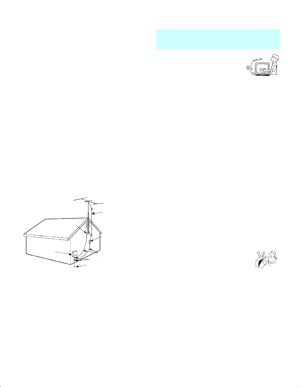
Antennas
Outdoor Antenna Grounding
If an outdoor antenna is installed, follow the precautions
below. An outdoor antenna system should not be located
in the vicinity of overhead power lines or other electric
light or power circuits, or where it can come in contact
with such power lines or circuits.
WHEN INSTALLING AN OUTDOOR ANTENNA
SYSTEM, EXTREME CARE SHOULD BE TAKEN TO
KEEP FROM CONTACTING SUCH POWER LINES
OR CIRCUITS AS CONTACT WITH THEM IS
ALMOST INVARIABLY FATAL.
Be sure the antenna system is grounded so as to provide
some protection against voltage surges and built-up static
charges.
Section 810 of the National Electrical Code (NEC) in
USA and Section 54 of the Canadian Electrical Code in
Canada provides information with respect to proper
grounding of the mast and supporting structure,
grounding of the lead-in wire to an antenna discharge
unit, size of grounding conductors, location of antenna
discharge unit, connection to grounding electrodes, and
requirements for the grounding electrode.
Antenna Grounding According to the NEC
Refer to section 54-300 of Canadian Electrical Code for
Antenna Grounding.
Antenna lead-in wire
Ground clamp
Antenna lead-in wire
Electrical
service
equipment
NEC: National
Electrical Code
(NEC Section 810-20)
Grounding conductors
(NEC section 810-21)
Ground clamps
Power service grounding
electrode system (NEC Ar t
250 Part H)
Cleaning
❑ Clean the rear cover area of the TV regularly. Dust
in the rear cover area may cause a problem with the
cooling system of the TV set.
❑ Clean the cabinet of the TV with a
dry soft cloth. To remove dust from
the screen, wipe it gently with a soft
cloth. Stubborn stains may be
removed with a cloth slightly
dampened with solution of mild soap and warm
water. Never use strong solvents such as thinner or
benzine for cleaning. If the picture becomes dark
after using the TV for a long period of time, it may
be necessary to clean the inside of the TV. Consult
qualified service personnel.
❑ Unplug the AC power cord when cleaning this unit.
Cleaning this unit with a plugged AC power cord
may result in electric shock.
On Contamination on the Screen Surface
The screen surface has a special coating to reduce
reflections. To prevent screen damage, clean the screen as
follows:
❑ Clean the screen with a soft cloth.
❑ To remove hard contamination, use a cloth
moistened with a solution of mild detergent and
water. Do not spray cleaning solution directly onto
the TV. It should only be sprayed to moisten the
cleaning cloth.
❑ Do not use any type of abrasive pad, alkaline
cleaner, acid cleaner, scouring powder, chemical
cloth, or solvent such as alcohol, benzene or thinner,
as these may scratch the screen's coating.
Service
Damage Requiring Service
Do not attempt to service the set by yourself
since opening the cabinet may expose you to
dangerous voltage or other hazards.
Unplug the set from the wall outlet and refer
servicing to qualified service personnel.
Replacement Parts
When replacement parts are required, be sure the service
technician certifies in writing that he has used
replacement parts specified by the manufacturer that have
the same characteristics as the original parts.
Unauthorized substitutions may result in fire, electric
shock or other hazards.
See “Replacing the Lamp” on page 76.
4
Page 7
For Safety
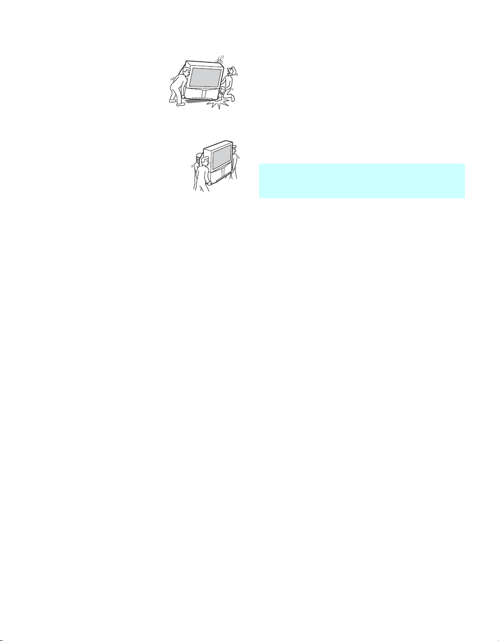
Be Careful when Moving
the TV
When you place the TV in position,
be careful not to drop it on your foot
or fingers.
Watch your footing while installing
the TV.
Carry the TV in the Specified
Manner
If you carry the TV in a manner other than
the specified manner and without the
specified number of persons, it may drop
and a serious injury may be caused. Be
sure to follow the instructions mentioned below.
❑ Carry the TV with the specified number of persons
(see page 12).
❑ Do not carry the TV holding the speaker grill.
❑ Hold the TV tightly when carrying it.
❑ Before carrying the TV, disconnect any accessories
or cables.
About the LCD projection TV
Although the LCD projection TV is made with highprecision technology, black dots may appear or bright
points of light (red, blue, or green) may appear constantly
on the LCD screen. This is a structural property of the
LCD panel and is not a defect.
Installation
❑ If direct sunlight or other strong illumination shines
on the screen, part of the screen may appear white
due to reflections from behind the screen. This is a
structural property of the LCD projection TV.
Do not expose the screen to direct illumination or
direct sunlight.
❑ The picture quality may be affected by your viewing
position. For the best picture quality, install your TV
according to “Recommended Viewing Area” on
page 13.
❑ When installing your TV against a wall, keep it at
least 4 inches (10 cm) from the wall.
Projection Lamp
❑ Your TV uses a projection lamp as its light source. It
is time to replace the lamp with a new one (not
supplied) when:
• the lamp replacement indicator on the front panel
blinks in red,
• screen images become dark,
• no image appears on the display after prolonged
use.
❑ In rare instances, the bulb may pop inside the lamp
unit, but the lamp unit is designed to contain all of
broken glass pieces inside the lamp unit. (see
“Replacing the Lamp” on page 76)
❑ When the lamp eventually burns out, you may hear
a noticeable pop sound. This is normal and is
inherent in this type of lamp.
Cooling Fan
❑ This TV uses a cooling fan. You may hear the noise
of fan running, depending on the placement of your
TV. The noise may be more noticeable during the
night or when the background noise level is low.
5
Page 8

Contents
Introducing the Sony TV
Presenting the Sony TV ...........................................8
Package Contents.............................................8
Features............................................................8
Enjoying Your TV .................................................10
Notes on the TV.............................................10
Screen.............................................................10
Indicators .......................................................11
Projection Lamp.............................................11
Installing the TV ....................................................12
Carrying Your TV..........................................12
Take Precaution during Installation...............13
To Prevent the TV from Falling ....................13
When Installing Your TV Against a Wall .....13
Recommended Viewing Area........................13
TV Front Panel and Connectors.............................14
Front Panel.....................................................14
Front and Rear Panel Connectors ..................15
Connecting the TV
Overview................................................................17
Making Video and Audio Connections .........17
About Using S VIDEO..................................18
About Using HDMI to DVI Adapter.............18
Basic Connections..................................................19
Cable System or VHF/UHF...........................20
Cable Box and Antenna .................................21
Cable Box ......................................................22
Satellite Receiver...........................................23
Digital Cable Box
Or Digital Satellite Receiver..........................24
Using CableCARD
About Using CableCARD
Activating CableCARD Service ....................25
Removing the CableCARD
Equipment with HDMI Connection...............27
Equipment with DVI Connection ..................28
Equipment with Digital Audio (Optical) .......29
Setting Up the TV Channel List ............................30
Using Initial Setup .........................................30
Connecting Optional Equipment ...........................31
VCR and Cable ..............................................32
VCR and Cable Box ......................................33
Two VCRs for Tape Editing..........................35
TM
Device................................25
TM
Device.............25
TM
Device...........26
DVD Player with Component
Video Connectors ..........................................36
DVD Player with
S VIDEO and Audio Connectors...................37
Camcorder or PlayStation..............................38
Audio Receiver..............................................39
Watching the TV
Overview................................................................41
Inserting Batteries into the Remote Control..........41
Button Descriptions ...............................................42
Programming the Remote Control.........................44
Manufacturer’s Codes............................................45
Using Other Equipment with Your Remote
Control ...........................................................46
Special Buttons on the Remote Control.................48
Using the GUIDE Button...............................48
Using the WIDE Button.................................50
Using the FREEZE Button ............................51
Using the JUMP Button.................................51
Introducing WEGA GATE
Overview of WEGA GATE...................................52
Using Favorites in WEGA GATE .........................54
Using Cable in WEGA GATE...............................54
Using Antenna in WEGA GATE ..........................55
Using External Inputs in WEGA GATE ...............55
Using Settings in WEGA GATE...........................55
Using the Settings
Overview................................................................56
Accessing the Video Settings ................................58
Selecting Video Options ................................58
Accessing the Audio Settings................................60
Selecting Audio Options................................60
Accessing the Screen Settings ...............................62
Selecting Screen Options...............................62
Accessing the Channel Settings.............................64
Selecting Channel Options ............................64
Accessing the Parental Lock Settings....................66
Selecting Parental Lock Options ...................66
Viewing Blocked Programs...........................67
Selecting Custom Rating Options..................68
6
Page 9

Accessing the Setup Settings.................................70
Selecting Setup Options.................................70
Programming Caption Vision ........................72
Accessing the Applications Settings......................73
Selecting Applications Options .....................73
Other Information
Overview................................................................75
Contacting Sony.....................................................75
Replacing the Lamp...............................................76
How to Replace the Lamp .............................76
Troubleshooting.....................................................80
Remote Control..............................................80
CableCARD
Video..............................................................81
Audio .............................................................82
Channels.........................................................82
General...........................................................83
Specifications.........................................................84
Optional Accessories .............................................85
TM
Device ..................................80
Index
Index ......................................................................87
7
Page 10

Introducing the Sony TV
Presenting the Sony TV
Thank you for purchasing this Sony’s HD LCD Projection TV.
This manual is for models KDF-E55A20 and KDF-E60A20.
Instructions in this manual are written for the remote control. Similar
controls are also found on the TV console.
Package Contents Along with your new TV, the packing box contains a remote control and two
AA (R6) batteries. These items are all you need to set up and use the TV.
Also included in the box are this operating manual and a Quick Setup Guide
poster.
Features Some of the features that you will enjoy with your new TV include:
❑ WEGA GATE
easily navigate to the most convenient TV functions: favorite channels,
cable channels, antenna channels, external input list or settings.
❑ WEGA Engine: Delivers superb picture quality from any video source
by minimizing the signal deterioration caused by digital-to-analog
conversion and stabilizing the signal processing. This engine features
unique Sony technology, including:
● The first step in the digital processing system, Composite
Component Processor (CCP-X), which enhances input signal-tonoise ratio by chroma decoder digital processing.
● DRC
line doublers, the DRC Multifunction feature replaces the signal’s
NTSC waveform with the near-HD equivalent by digital mapping
processing. The DRC Palette option lets you customize the level of
detail (Reality) and smoothness (Clarity) to create up to three
custom palettes.
❑ Integrated HDTV: You can watch digital television programs and
enjoy the improved audio/video quality offered by these programs.
❑ CableCARD
encrypted cable channels — without the need for a set-top box — that
will enable you to receive not only standard definition but also high
definition television. The CableCARD device, which is provided by
your cable TV company, is inserted into the TV’s rear panel
CableCARD slot. After the service is activated with your cable TV
company, the card replaces the need for a separate set-top box. (Check
with your cable TV company about CableCARD service details,
limitations, pricing, and availability. For more information about
CableCARD device in this manual, see page 25.)
™
: WEGA GATE is a new feature that allows you to
®
(Digital Reality Creation)-MF V1: Unlike conventional
™
slot: Provides cable subscribers with access to digitally
8
Page 11

Introducing the Sony TV
❑ HDMI (High-Definition Multimedia Interface): Provides an
uncompressed, all-digital audio/video interface between this TV and
any HDMI-equipped audio/video component, such as a set-top box,
DVD player, and A/V receiver. HDMI supports enhanced, or highdefinition video, plus multi-channel digital audio.
❑ Component Video Inputs: Offer the best video quality for DVD (480p,
480i) and digital set-top box (1080i, 720p, 480p, 480i) connections.
❑ S VIDEO Inputs: Provide a high-quality image from connected
equipment.
❑ CineMotion
®
: Using the reverse 3-2 pull down technology, the
CineMotion feature provides smoother picture movement when playing
back movies or other video sources on film.
❑ Steady Sound
®
: Equalizes volume levels so there is consistent output
between programs and commercials.
❑ Wide Screen Mode: Allows you to watch 4:3 normal broadcasts in
wide screen mode (16:9 aspect ratio).
❑ Favorite Channels: Allows you to navigate a list of up to sixteen
favorite channels without leaving the current channel.
❑ Parental Control: V-Chip technology allows parents to block
unsuitable programming from younger viewers.
Introducing the Sony TV
9
Page 12

Introducing the Sony TV
Enjoying Your TV
To enjoy your TV for years to come and maintain its original picture quality,
you should perform periodic maintenance.
Notes on the TV To enjoy clear picture
Prevent sunlight or other light sources from shining directly on to the
❑
screen.
❑ The screen surface is easily scratched. Do not rub, touch, or tap it with
sharp or abrasive objects (see “Cleaning” on page 4).
When not using the TV for a long period of time
Unplug the AC power cord from the outlet if you anticipate not using
❑
the TV for more than a week.
When turning off the power
The cooling fan will continue to operate for about two minutes. Allow
❑
several minutes before unplugging from the outlet or switching the
breaker off.
On moisture condensation
If your TV is moved directly from a cold to a warm location or is placed
❑
in a humid room, or if the room temperature changes suddenly, the
picture may blur or show poor color. This is caused by moisture
condensation on the lenses inside. Wait a few hours to let the moisture
evaporate before turning on the TV. When the condensation has
evaporated, the picture will return to normal.
Screen To minimize reflection, the screen surface has a special coating.
Inappropriate cleaning methods could damage the screen surface. Special
care is required.
Cleaning the Screen Surface
Dust and dirt on the screen can affect the picture quality. To dust off the
screen use a soft cloth. Be sure to follow the cleaning instruction on page 4
for stubborn stains and dirt.
10
Page 13
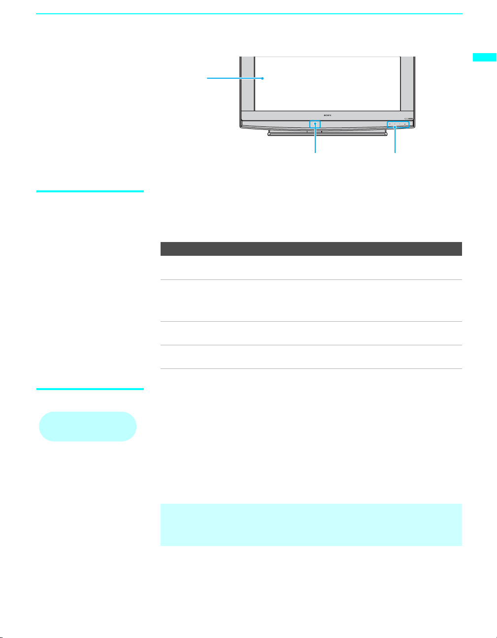
Screen
Introducing the Sony TV
POWER
LAMP TIMER POWER
Introducing the Sony TV
Projection lamp
Indicators
Indicators The indicators show the current status of your TV. If there is a change in the
condition or a problem with the TV, the indicators will flash or light up in
the manner described below to let you know that it requires your attention.
Indicator Flashing because...
POWER
(green) flashing
POWER
(red) flashing
TIMER indicator is
lit.
LAMP indicator
flashes.
The lamp for the light source is preparing to turn on. When
it is ready, it turns on.
The lamp cover is not securely attached. The red indicator
will continue to flash in intervals of 3 blinks at a time until
the lamp cover is placed correctly. When the lamp cover is
securely attached the TV will turn on with green indicator.
When one of the timer is set, the indicator will remain lit
(will not flash) even when the TV is turned off.
The projection lamp has burned out. Replace it with a new
one (see page 14).
Projection Lamp Your TV uses a projection lamp as its light source. As with any lamp, it has
How to replace the lamp,
see page 76.
lifespan and needs to be replaced when the Lamp indicator flashes or the
screen becomes darker. The projection lamp is located under the Control
Panel cover as shown in the diagram above. Note the following:
❑ After turning on your TV, it may take a while (1 minute or less) before
the picture appears.
❑ When the projection lamp wears out, the screen goes dark. Replace the
lamp with a new Sony XL-2200 replacement lamp (not supplied).
✍ The light emitted from the lamp is quite bright when your TV is in use. To
avoid eye discomfort or injury, do not look into the light housing when
the power is on.
11
Page 14
Introducing the Sony TV
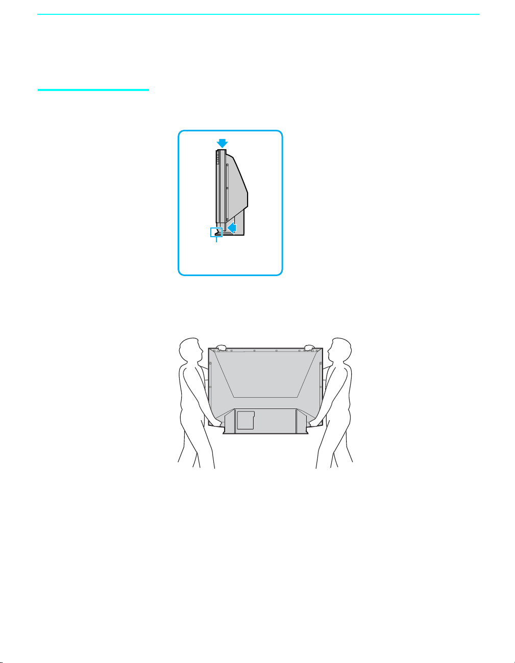
Installing the TV
Carrying Your TV Carrying the TV requires at least two people. Do not hold by the pedestal or
the front panel of the TV. Doing so may cause these parts to break off.
Do not grasp the pedestal
or the front panel of the
TV.
When moving the TV, place one hand in the hole on the lower portion of the
TV while grasping the top with the other hand, as shown in the illustration
below.
12
If you have connected cables and cords, be sure to unplug them before
moving the TV.
Page 15
Introducing the Sony TV
min.
6.8 ft.
(approx.
2.1 m
62.5
65
min. 6.6 ft. (approx. 2.0 m)
50"
min. 5.9 ft. (approx. 1.8 m)
42"
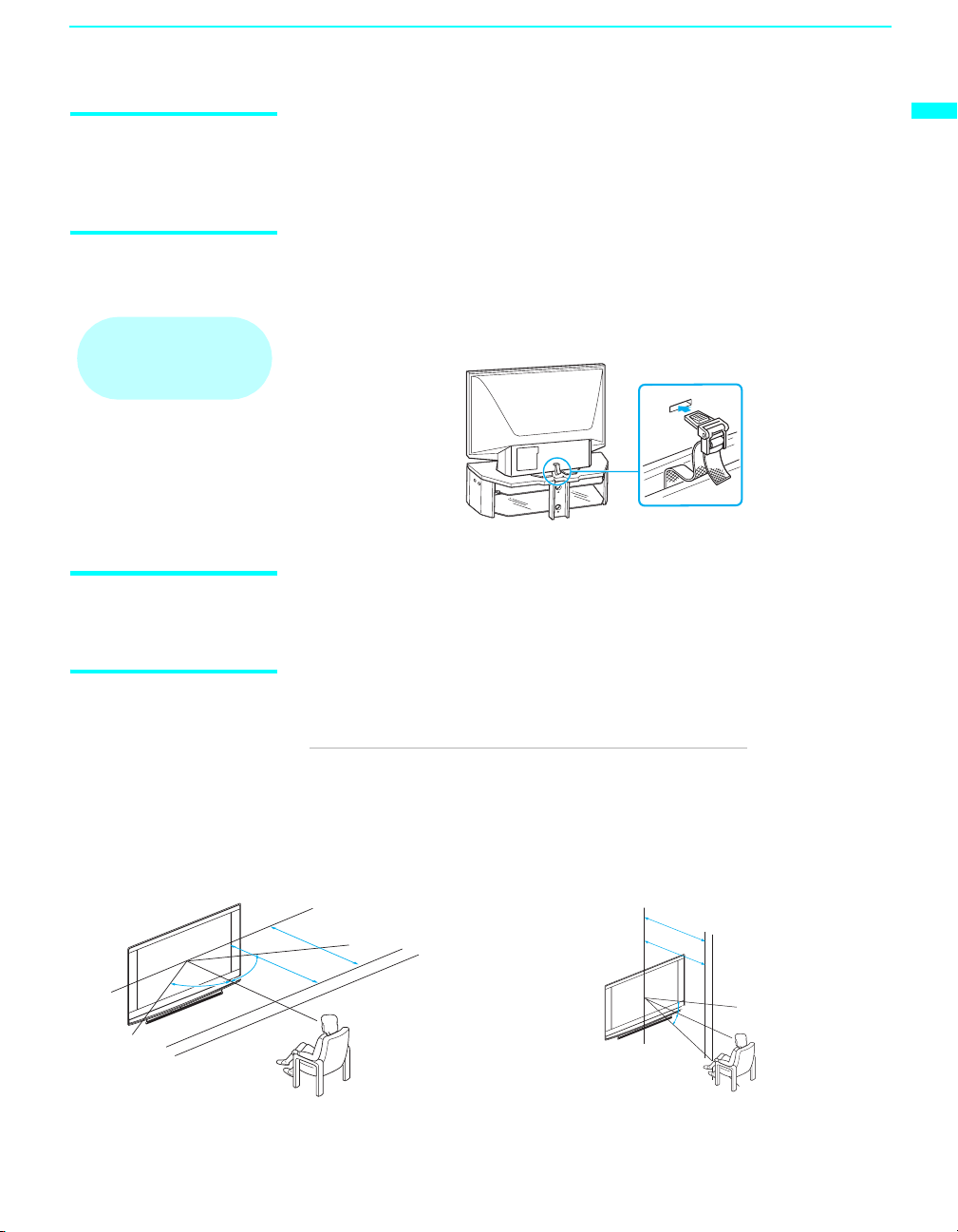
Take Precaution during Installation
To Prevent the TV from Falling
When using the SU-GW12
stand for your TV, you
must use the support belt.
When Installing Your TV Against a Wall
To ensure the safety of children and the TV, keep children away from the TV
during installation. Climbing on or pushing the TV or its stand may cause it
to fall and damage the TV.
As a protective measure, secure the TV as follows.
Using the TV stand with support belts
❑
Sony strongly recommends using the TV stand SU-GW12 with a
support belt designed for your TV.
Keep your TV at least 4 inches (10 cm) away from the wall to provide proper
ventilation.
Introducing the Sony TV
Recommended Viewing Area
Horizontal Viewing Area
min. 6.8 ft. (approx. 2.1 m)
min. 5.9 ft. (approx. 1.8 m)
65
62.5˚
62.5
62.5˚
Your viewing position may affect the picture quality.
For the best picture quality, install your TV within the areas shown below.
Model Viewing distance
KDF-E55A20 min. 6.8 ft. (approx. 2.1 m)
KDF-E60A20 min. 7 ft. (approx. 2.2 m)
Vertical Viewing Area
min. 6.6 ft. (approx. 2.0 m)
min. 7 ft. (approx. 2.2 m)
50"
60"
55"
42"
˚
min. 7 ft. (approx. 2.2 m)
min.
60"
6.8 ft.
6.8 ft.
(approx.
(approx.
55"
2.1 m
2.1 m
27.5˚
27.5˚
)min.
)
13
Page 16
Introducing the Sony TV
15 4 3 2
TV Front Panel and Connectors
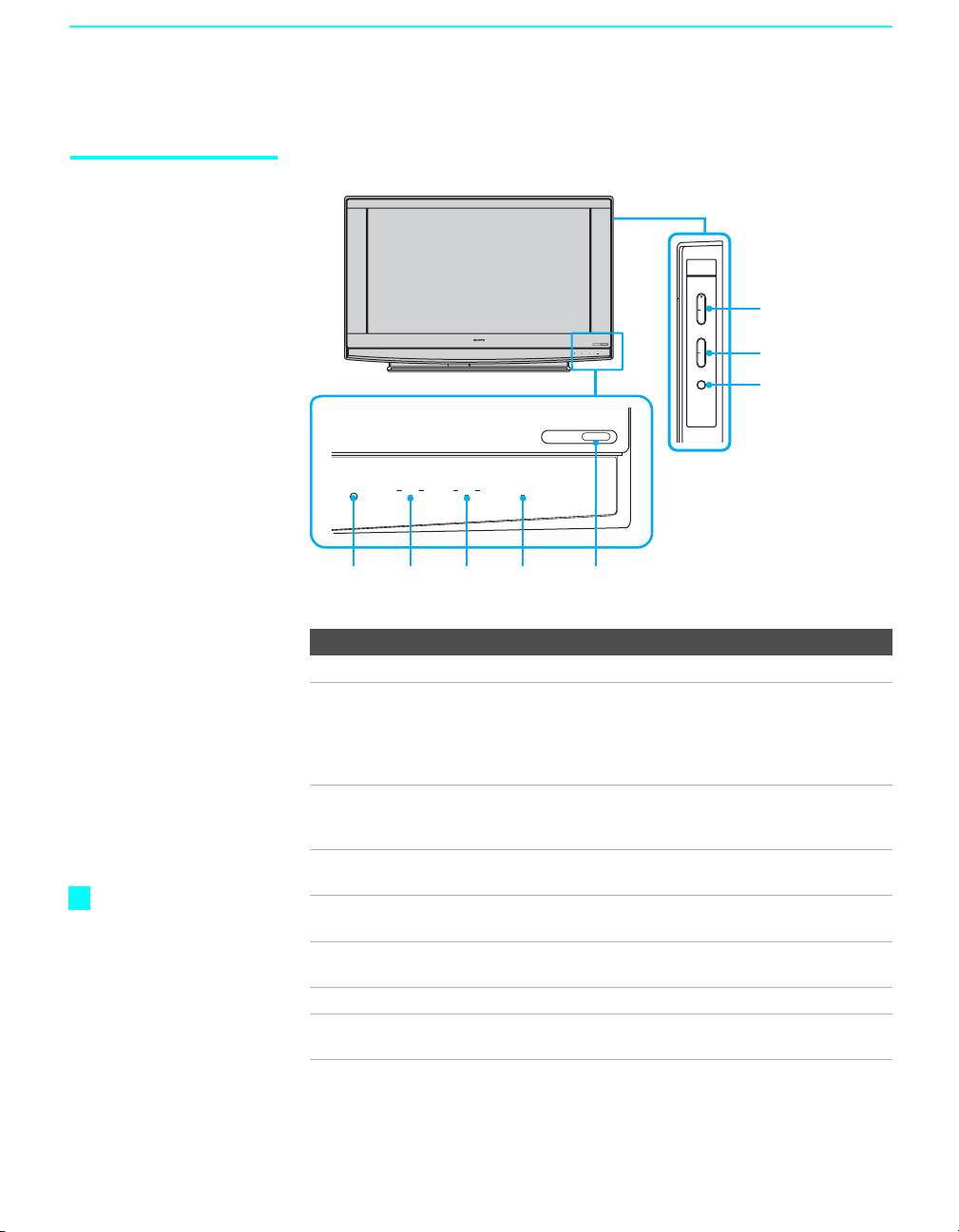
Front Panel
LAMP TIMER POWER
POWER
LAMP TIMER POWER
CHANNEL
3
#
POWER
VOLUME
TV/VIDEO
3
#
6
7
8
z
The CHANNEL +
button has a tactile dot.
Use the dot as a
reference when
operating the TV.
14
Item Description
1 POWER Press to turn on/off the TV.
2 POWER LED Lights up in green when the TV set is turned on. The LED
light does not light up when the main power is turned off.
If the LED blinks continuously, this may indicate the
display unit needs servicing (see “Contacting Sony” on
page 75).
3 TIMER LED When lit, indicates one of the timers is set. When the
timer is set, this LED will remain lit even if the TV set is
turned off. For details, see page 73.
4 LAMP LED
Lights up in red when the lamp for the light source has burned
out. For details, see “Replacing the Lamp” on page 76.
5 (IR) Infrared
Receiver
6 CHANNEL +/–
Receives IR signals from the remote control. Do not put
anything near the sensor, as its function may be affected.
Press to scan through channels. To scan quickly through
channels, press and hold either CHANNEL.
7 VOLUME +/– Press to adjust the volume.
8 TV/VIDEO Press to select among the TV’s tuner and other video
equipment inputs.
Page 17
Introducing the Sony TV
1 2
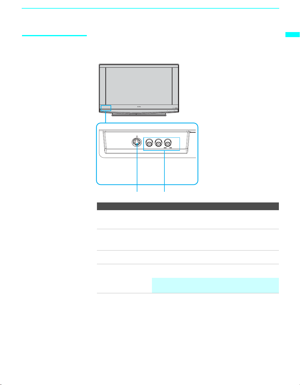
Front and Rear Panel Connectors
Front Panel of TV
VIDEO 2 INPUT
Press up lightly
to release the
console
S VIDEO VIDEO L (MONO) R AUDIO
Connection Description
1 S VIDEO
(Front and rear)
Connects to the S VIDEO OUT jack of your VCR or other
S VIDEO-equipped video component. Provides better
picture quality than the Video IN jack.
2 VIDEO/ L(MONO)-
AUDIO- R
(Front and rear)
3 HD/DVD IN (1080i/
720p/480p/480i)
4 AUDIO OUT
(VAR/FIX) L/R
Connects to the audio and video OUT jacks on your VCR
or other video component. A fourth video input (VIDEO 2)
is located on the front panel of the TV.
Connects to your DVD player’s or digital set-top box’s
component video (YPbPr) and audio (L/R) jacks.
Connects to the left and right audio inputs of your audio or
video component.
✍ AUDIO OUT jacks are operable only when the TV’s
POWER
LAMP TIMER POWER
Speaker is set to Off.
Introducing the Sony TV
(Continued)
15
Page 18
Introducing the Sony TV
4
1
2
3
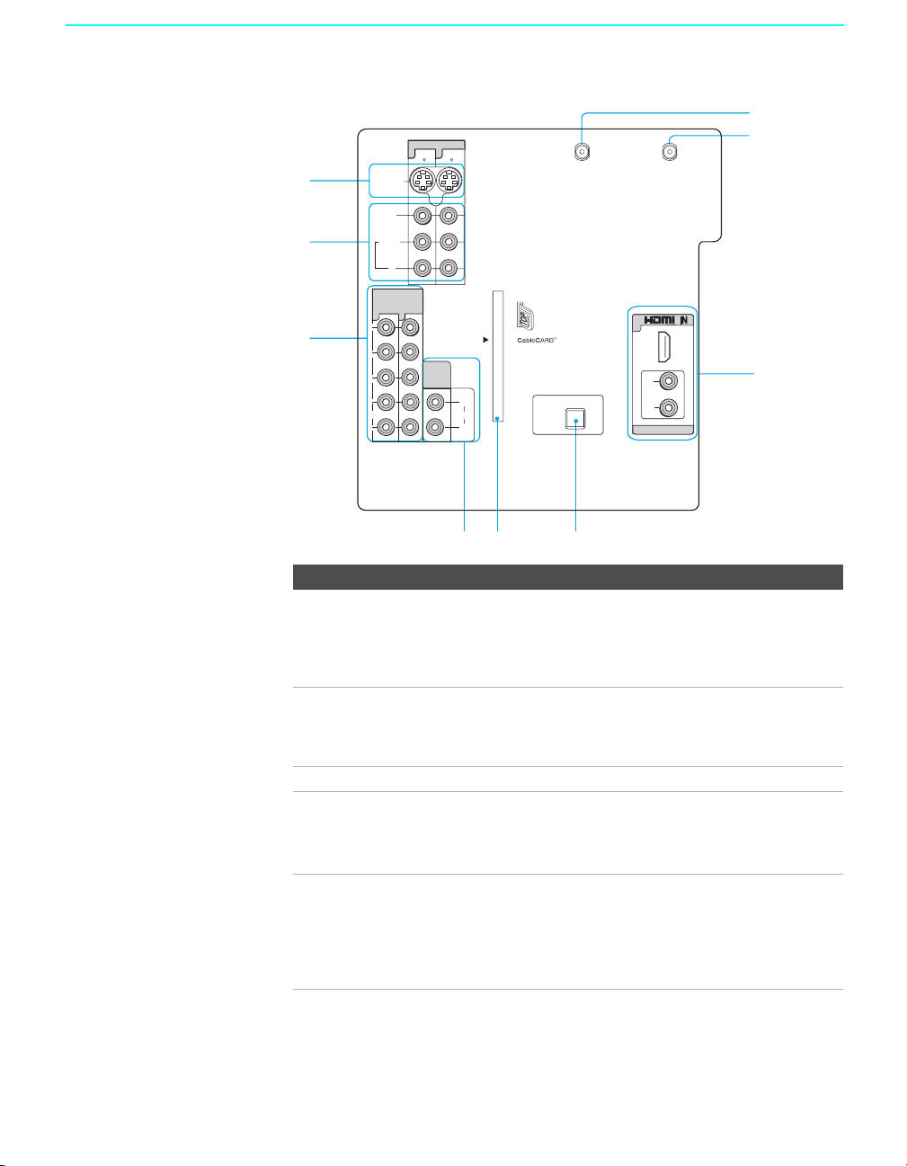
Rear of TV
S VIDEO
VIDEO
(MONO)
L
AUDI O
R
HD/DVD IN
(1080i/720p/
480p/480i)
45
Y
B
P
P
R
L
AUDIO
R
VIDEO IN
1
AUDI O
OUT
(VAR/FIX)
3
L
AUDI O
R
EJECT
56
VHF/UHF CABLE
6
L
PCM/DOLBY DIGITAL
DIGITAL
AUDIO
(OPTICAL)
OUT
R
AUDIO IN
7
8
9
Connection Description
5 CableCARD slot CableCARD device provides cable subscribers with access
to secure, digitally encrypted cable channels - without the
need for a set-top box - that will enable you to receive not
only standard definition but also high definition television.
For more information, see page 25.
6 DIGITAL AUDIO
(OPTICAL OUT)
Connects to the optical audio input of a digital audio
component that is PCM/Dolby Digital compatible.
(PCM/DOLBY*
DIGITAL)
7 VHF/UHF Connects to your VHF/UHF antenna.
8 CABLE Connects to your cable signal. This CABLE input jack, in
conjunction with the VHF/UHF input jack, lets you set up
your TV to switch between scrambled channels (coming
through a cable box) and unscrambled cable channels.
9 HDMI
(VIDEO 6 IN)
HDMI (High-Definition Multimedia Interface) provides an
uncompressed, all-digital audio/video interface between
this TV and any HDMI-equipped audio/video component,
such as a set-top box, DVD player, and A/V receiver.
HDMI supports enhanced, or high-definition video, plus
two-channel digital audio.
*
Manufactured under license from Dolby Laboratories.
“Dolby” and the double-D symbol are trademarks of Dolby Laboratories.
16
Page 19
Connecting the TV
Overview
Your new LCD Projection TV can receive both analog and digital
broadcasting signals from antenna, satellite and cable TV.
To display clear crisp pictures, you must connect your TV correctly and
choose the correct display format (see Wide button on page 50). It is strongly
recommended to connect the antenna using a 75-ohm coaxial cable to
receive optimum picture quality signal. A 300-ohm twin lead cable can be
easily affected by radio noise and the like, resulting in signal deterioration.
If you use a 300-ohm twin lead cable, keep it as far away as possible from
the TV.
Connecting the TV
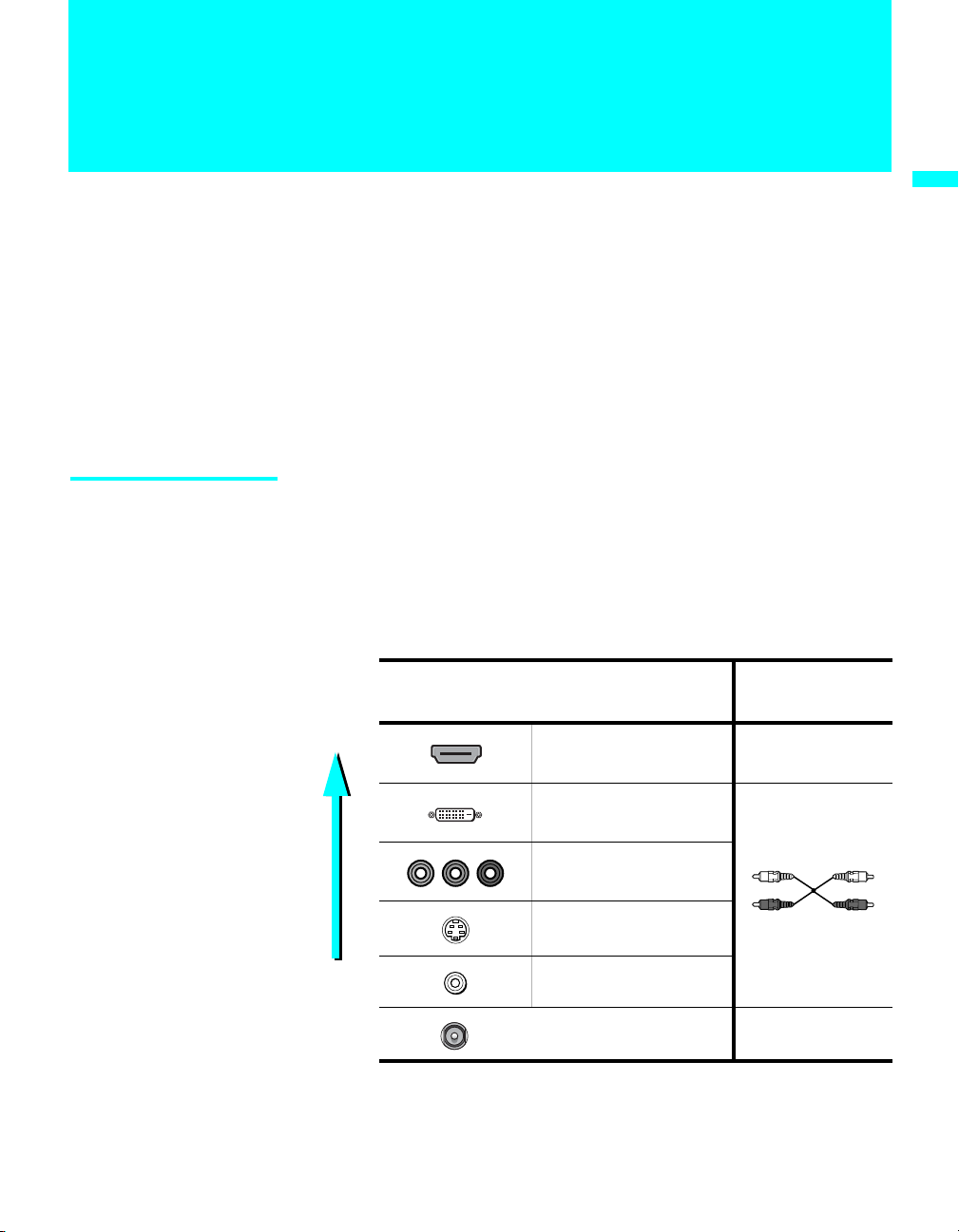
Making Video and Audio Connections
The signals that enter your TV and connected devices will need to output in
the correct format using the suitable connections. Below are different types
of video connectors available these days. Your TV comes with all types of
connectors with the exception of the DVI connector but your cable box or
satellite receiver may be equipped with this type. When connecting your TV,
use the inputs that are available on your devices that provide the best video
performance, as described below.
Best Video
Performance
Connector Type
HDMI (High-Definition
Multimedia Interface)
DVI (Digital Visual
Interface)
Component
S VIDEO
Composite
RF/Coaxial No
*
Separate Audio
connection
required
No
Ye s
(not supplied)
* An adapter is necessary when connecting DVI equipped device to this TV,
see page 18.
17
Page 20

Connecting the TV
About Using
S VIDEO
If the optional equipment you are connecting has an S VIDEO jack
(shown at left), you can use an S VIDEO cable for improved picture
quality (compared to an A/V cable). Because S VIDEO carries only
the video signal, you also need to connect audio cables for sound, as
shown below.
Example of an S VIDEO Connection
Equipment with S VIDEO
S VIDEO
cable
Rear of TV
S VIDEO
VIDEO
(MONO)
L
AUDIO
Audio cable
VIDEO IN
1 3
R
Cables are often
color-coded to connectors.
Connect red to red,
white to white, etc.
About Using HDMI to DVI Adapter
18
If you are connecting equipment with DVI connector with this TV, you will
need to use an adapter. You can use an HDMI to DVI cable or an HDMI
adapter (not supplied). Both are available at your local electronics store.
When you use the adapter, you will also need to use separate audio cables for
sound as DVI connector is for video signals only.
HDMI to DVI Cable
HDMI adapter
Audio cable
Page 21

Basic Connections
Connecting the TV
The way in which you connect your TV will vary, depending on how your
home receives a signal (antenna and satellite, cable, cable box) and whether
or not you plan to connect a VCR.
If You Are Connecting See Page
Cable System or VHF/UHF
❏ No cable box or VCR
Cable Box and Antenna
❏ Cable box unscrambles only some channels
(usually premium channels)
❏ No VCR
Cable Box
❏ Cable box unscrambles all channels
❏ No VCR
Satellite Receiver 23
Digital Cable Box or Digital Satellite
Receiver
If you are connecting a VCR
❑
See the connections described on pages 32 and 33.
20
21
22
24
Connecting the TV
19
Page 22
Connecting the TV
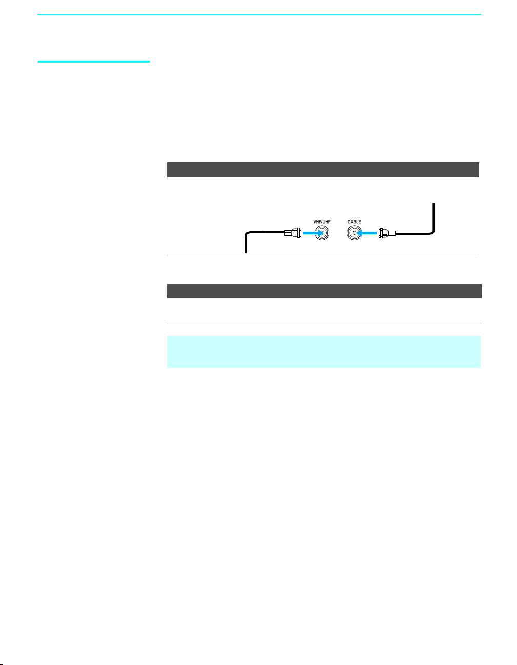
Cable System or VHF/UHF
For best results, use this connection if you:
❑
Have a cable and/or an antenna.
(This is convenient if you are using a separate rooftop antenna to receive
additional channels that are not provided by your cable TV company.)
❑ Do not have a cable box or VCR. (If you have a cable box, see pages 21
to 22. If you have a VCR, see pages 32 and 33.)
Antenna System
Cable Type Connect As Shown
Cable TV
(CATV) and
Antenna
Notes on Using This Connection
To Do This... Do This ...
the TV’s input between
Switch
the cable and antenna
Antenna cable
Press ANT to switch back and forth between the
TV’s VHF/UHF and CABLE inputs.
CATV cable
✍ Do not use an indoor antenna, which is especially susceptible to radio
noise.
20
Page 23
Connecting the TV
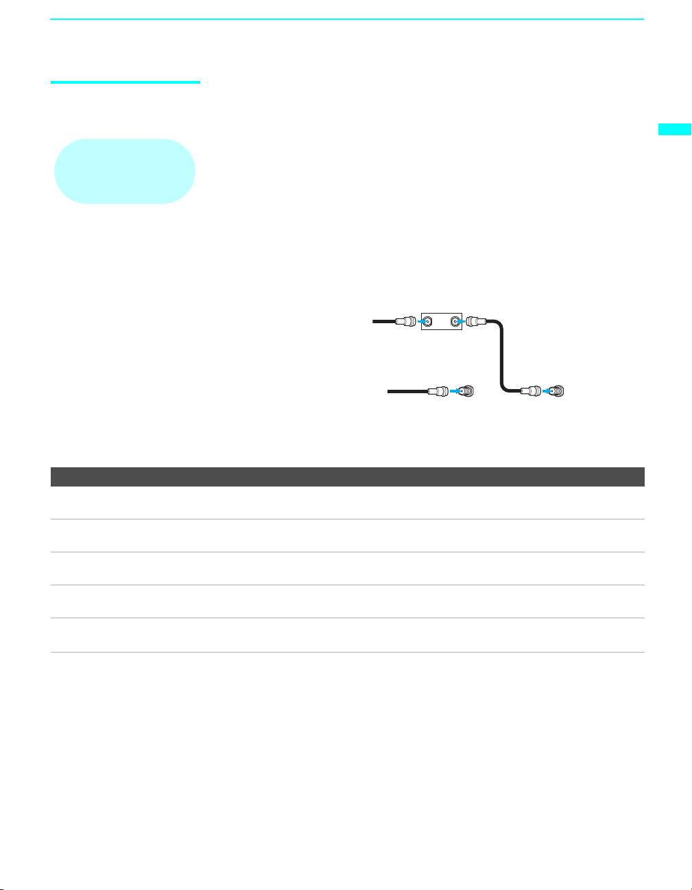
Cable Box and Antenna
For best results, use this connection if:
❑
Your cable company scrambles some channels, such as premium
channels (which requires you to use a cable box), but does not scramble
Before connecting a
cable box, see “Using
CableCARD Device” on
page 25.
all channels.
❑ You do not have a VCR. (If you have a VCR, see pages 32 and 33.)
With this connection you can:
❑
Use the TV’s remote control to change channels coming through the
cable box to the TV’s cable input. (You must first program the remote
control for your specific cable box; see “Programming the Remote
Control” on page 44.)
❑ Use the TV’s remote control to change channels coming directly into
the TV’s VHF/UHF input jack.
CATV cable
Antenna
cable
Notes on Using This Connection
To Do This ... Do This ...
Use the cable box Tune the TV to the channel the cable box is set to (usually channel 3
or 4) and then use the cable box to switch channels.
Set up the TV remote control to operate the cable
box
Activate the remote control to operate the cable
box
Program the remote control. See “Programming the Remote
Control” on page 44.
Press SAT/CABLE (FUNCTION) once, and the SAT/CABLE
indicator lights up.
Prevent the accidental switching of TV channels When using the cable box, ensure that the TV remains tuned to the
channel that the cable box is set to (usually channel 3 or 4).
the TV’s input between the cable box and
Switch
antenna
Press ANT to switch back and forth between the TV’s VHF/UHF
(scrambled channels) and CABLE (unscrambled) inputs.
IN OUT
Cable box
VHF/UHF Cable
Coaxial
cable
Rear of TV
Connecting the TV
21
Page 24
Connecting the TV
F
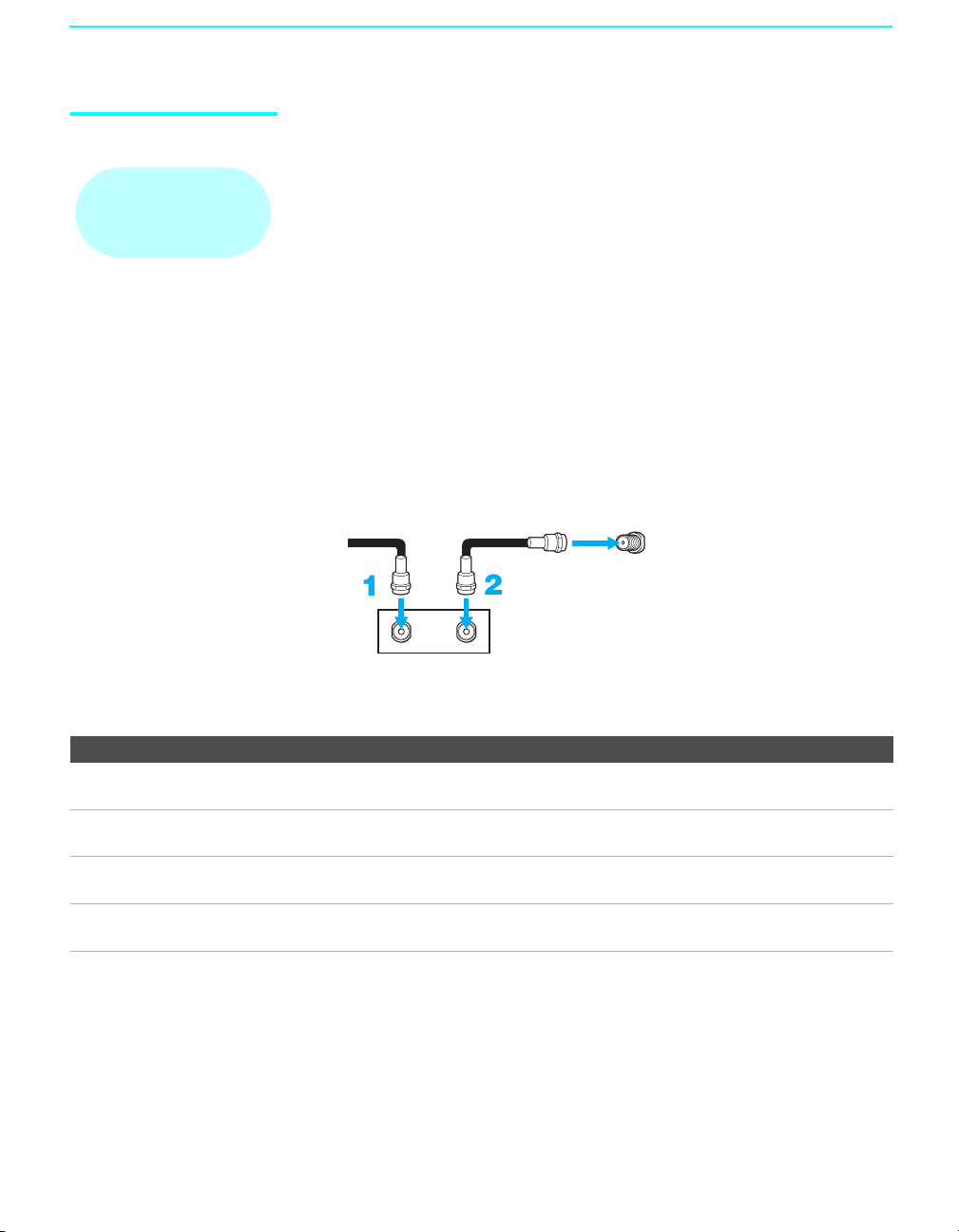
Cable Box For best results, use this connection if:
❑
Your cable company scrambles all channels, which requires you to use a
Before connecting a
cable box, see “Using
CableCARD Device” on
page 25.
cable box.
❑ You do not have a VCR. (If you have a VCR, see pages 32 and 33.)
With this connection you can:
❑
Use the TV’s remote control to change channels coming through the
cable box to the TV’s VHF/UHF jack. (You must first program the
remote control for your specific cable box.)
To connect the cable box
1 Connect the CATV cable to the cable box’s input jack.
2 Use a coaxial cable to connect the cable box’s output jack to the TV’s
VHF/UHF jack.
3 Run Auto Program, as described in “Setting Up the TV Channel List”
on pages 30.
CATV cable
IN
Cable box
Notes on Using This Connection
To do this... Do This ...
Use the cable box Tune the TV to the channel the cable box is set to (usually channel 3
Set up the TV remote control to operate the cable
box
Activate the remote control to operate the cable
box
Prevent the accidental switching of TV channels When using the cable box, ensure that the TV remains tuned to the
Coaxial cable
OUT
or 4) and then use the cable box to switch channels.
Program the remote control. See “Programming the Remote
Control” on page 44.
Press SAT/CABLE (FUNCTION) once, and the SAT/CABLE
indicator lights up.
channel that the cable box is set to (usually channel 3 or 4).
VHF/UH
Rear of TV
22
Page 25

Connecting the TV
Satellite Receiver Disconnect all power sources before making any connections.
1 Connect the satellite antenna cable to the satellite receiver’s
SATELLITE IN jack.
2 Use A/V and S VIDEO cables to connect the satellite receiver’s AUDIO
and S VIDEO OUT jacks to the TV’s AUDIO and S VIDEO IN jacks.
3 Use a coaxial cable to connect your cable to the TV’s CABLE jack, or
your antenna to the TV’s VHF/UHF jack.
Rear of TV
VIDEO IN
S VIDEO
VIDEO
(MONO)
L
AUDIO
R
1 3
VHF/UHF CABLE
Coaxial cable
Connecting the TV
S VIDEO
Cables are often
color-coded to connectors.
Connect red to red,
white to white, etc.
VIDEO (yellow)
AUDIO-L (white)
AUDIO-R (red)
A/V cable (not supplied)
S VIDEO cable (not supplied)
Satellite receiver
Satellite
antenna
cable
✍ If your satellite receiver is not equipped with S VIDEO, use a VIDEO cable
(yellow) instead of the S VIDEO cable.
23
Page 26

Connecting the TV
Digital Cable Box Or Digital Satellite Receiver
Digital cable box or satellite
RF coaxial cable
Disconnect all power sources before making any connections.
1 Connect the RF coaxial cable from the CATV or Satellite dish to the
INPUT of the digital cable box or digital satellite receiver.
Rear of TV
HD/DVD IN
(1080i/720p/
480p/480i)
4 5
Y
P
B
P
R
L
AUDI O
R
Cables are often
color-coded to connectors.
Connect red to red,
white to white, etc.
Audio cable
(not supplied)
P
PR
Component video cable
(not supplied)
AUDIO-L
(white)
AUDIO-R
(red)
Y
B
2 Use a component video cable to connect the YPBPR jacks of your digital
cable box or digital satellite receiver to the TV’s component jacks.
AUDI O
OUT
(VAR/FIX)
L
AUDI O
R
24
✍ Component video (YPBPR) connection is necessary to view digital
broadcastings in 1080i, 720p, 480i and 480p. This TV displays all format
types of picture in a resolution of 1,368 dots x 768 lines.
3 Use an audio cable to connect the AUDIO OUT jack of the digital cable
box or digital satellite receiver to the TV’s AUDIO IN jacks.
✍ The component Jacks (YPBPR) do not provide audio, so audio cables
must be connected to provide sound.
Page 27

Using CableCARD Device
The CableCARD device provides cable subscribers with access to digitally
encrypted cable channels — without the need for a set-top box — that will
enable you to receive not only standard definition but also high definition
television. The CableCARD device, which is provided by your cable TV
company, is inserted into the TV’s rear panel CableCARD slot. After the
service is activated with your cable TV company, the card replaces the need
for a separate set-top box.
Connecting the TV
Connecting the TV
About Using
CableCARD
Device
Activating CableCARD Service
If you are planning to use a separate cable box for digital cable TV services,
you may be able to receive programming using this TV with the
CableCARD device instead — except in the following circumstances:
❑ Your cable TV company does not provide CableCARD service in your
viewing area.
❑ You want to access your cable TV company’s interactive or advanced
features (such as video-on-demand or, in some cases, pay-per-view). At
this time, these services require a bidirectional link, which are only
available through the use of a separate set-top box. CableCARD device is
currently a unidirectional device only, and cannot provide these advanced
services.
Check with your cable TV company for CableCARD service details,
limitations, pricing, and availability, all of which are determined by your
cable TV company — not Sony.
Before you can use CableCARD service, you need to insert the CableCARD
device (supplied by your cable TV company) and activate the service, as
described below:
1 Insert the CableCARD device into the TV’s CableCARD slot.
S VIDEO
VIDEO
(MONO)
L
AUDIO
R
HD/DVD IN
(1080i/720p/
480p/480i)
45
Y
P
B
P
R
L
AUDIO
R
VIDEO IN
1
3
AUDIO
OUT
(VAR/FIX)
AUDIO
L
R
EJECT
VHF/UHF CABLE
6
PCM/DOLBY DIGITAL
DIGITAL
AUDIO
(OPTICAL)
OUT
L
R
AUDIO IN
✍ CAUTION: Inserting the CableCARD device incorrectly may result in
permanent damage to the card and the TV.
(Continued)
25
Page 28
Connecting the TV
z
You can also access
information about your
CableCARD device in
the Applications Menu
(see page 74).
2 Gently push the card into the slot until it locks into place.
3 After 1-2 minutes, the CableCARD device setup screen is automatically
displayed. This screen includes information your cable TV company
will request before they can activate your service.
4 Follow the displayed instructions: Phone your cable TV company. A
representative will guide you through the activation process.
5 After your CableCARD device is activated, your cable TV company
will download the service information, including the channel list, to the
CableCARD device. After the CableCARD device has acquired
channels from your cable TV company, the TV tunes to the lowest
available channel.
Removing the
CableCARD
Device
In the event you want to cancel your service, contact your cable TV
company.
✍ Once the CableCARD
digital cable TV programming services that require CableCARD device.
device is removed, your TV will no longer decrypt
1 Push the eject button on the TV’s CableCARD slot to release the card.
Eject button
2 Pull the CableCARD device straight out of the slot to remove it.
To install a different CableCARD
“Activating CableCARD Service” on page 25.
device, follow the instructions in
26
Page 29

Connecting the TV
Equipment with HDMI Connection
z
The HDMI jack
provides both video
and audio signals, so it
is not necessary to
connect the audio
cable.
Equipment with HDMI output
Use this hookup if:
❑ Your equipment has a High-Definition Multimedia Interface (HDMI).
Disconnect all power sources before making any connections
Use an HDMI cable (not supplied) to connect the equipment’s HDMI OUT
jack to the TV’s HDMI IN jack.
Use the HDMI IN 6 input connection.
Rear of TV
S VIDEO
VIDEO
(MONO)
L
AUDI O
R
HD/DVD IN
(1080i/720p/
480p/480i)
45
Y
B
P
P
R
L
AUDIO
R
VIDEO IN
1
AUDI O
OUT
(VAR/FIX)
3
L
AUDI O
R
EJECT
VHF/UHF CABLE
6
L
PCM/DOLBY DIGITAL
DIGITAL
AUDIO
(OPTICAL)
OUT
R
AUDIO IN
Connecting the TV
HDMI cable (not supplied)
27
Page 30

Connecting the TV
Equipment with DVI Connection
Equipment with HDMI output
If you are connecting with DVI-HDTV output, you can connect to the TV’s
HDMI IN jack by using an HDMI-to-DVI cable or an adaptor (both not
supplied).
Rear of TV
S VIDEO
VIDEO
(MONO)
L
AUDI O
R
HD/DVD IN
(1080i/720p/
480p/480i)
45
Y
B
P
P
R
L
AUDIO
R
VIDEO IN
1
AUDI O
(VAR/FIX)
OUT
3
L
AUDI O
R
VHF/UHF CABLE
PCM/DOLBY DIGITAL
DIGITAL
AUDIO
(OPTICAL)
EJECT
OUT
6
L
R
AUDIO IN
28
Audio cable
(not supplied)
HDMI-to-DVI adapter or
cable (not supplied)
AUDIO-R (red)
AUDIO-L (white)
✍ When using a DVI-HDMI cable or an adapter, be sure to connect the DVI
output connector first; then connect to the HDMI input on your TV.
Page 31

Connecting the TV
Equipment with Digital Audio (Optical)
You can use the TV's DIGITAL AUDIO (OPTICAL) OUT jack to connect a
digital audio device that is PCM/Dolby Digital compatible, such as an audio
amplifier.
Use an optical audio cable to connect the device's OPTICAL IN jack to the
TV's DIGITAL AUDIO (OPTICAL) OUT jack.
Rear of TV
S VIDEO
VIDEO
(MONO)
L
AUDIO
R
HD/DVD IN
(1080i/720p/
480p/480i)
45
Y
B
P
P
R
L
AUDIO
R
VIDEO IN
1
AUDIO
OUT
(VAR/FIX)
3
L
AUDIO
R
EJECT
VHF/UHF CABLE
6
L
PCM/DOLBY DIGITAL
DIGITAL
AUDIO
(OPTICAL)
OUT
R
AUDIO IN
Optical audio cable (not supplied)
The DIGITAL AUDIO
(OPTICAL) OUT jack is
available only when a
digital TV channel is
received.
Connecting the TV
Audio amplifier
LINE
OUT
L AUDIO R
LINE
IN
OPTICAL
IN
29
Page 32

Connecting the TV
Setting Up the TV Channel List
After you finish connecting the TV, you can run the Initial Setup to create a
list of available analog and digital channels. The Initial Setup screen appears
when you turn on the TV for the first time after hooking it up. If you choose
to set up the channels at a later time select the Auto Program option in the
Channel menu to scan available channels (see below).
✍ The Auto Program feature does not apply for installations that use a
cable box for all channel selection.
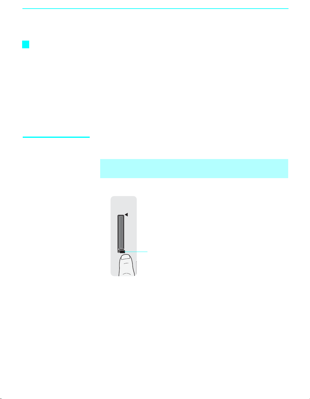
Using Initial Setup To run Initial Setup the first time you turn on your TV
TV POWER
1 Press to turn on the TV.
The Initial Setup screen appears.
2 Press V or v to highlight the on-screen
display language. Then press . The
message “First please connect cable/
antenna” appears. This may require 50+
minutes for completion and “Start auto program now?” appears.
3 Press V or v to highlight “Yes” then press .
Auto Program performed through Initial Setup will automatically create a
list of receivable channels from both VHF/UHF antenna and cable TV
channels if both sources are connected.
✍ Auto Program may take a while (20 to 50 minutes) to complete. A
progress bar is displayed while available channels are being scanned. If
you cancel the Auto Program before all receivable channels are scanned,
you may want to perform the task later (see “To run Auto Program at a
later time” below).
✍ If you selected “No” during the Initial Setup, the Initial Setup message
will appear each time you turn on the TV until you complete the Auto
Program as a reminder.
To run Auto Program at a later time
30
1 Select Settings in WEGA GATE, and then go to Channel settings.
2 Select Auto Program then select Start.
✍ Auto Program will create a list of receivable channels for the current
input (UHF/VHF antenna or CABLE). You will be required to run Auto
Program for each RF input to create a list of available channels from both
inputs.
Page 33

Connecting Optional Equipment
You can connect variety of optinal equipment to your TV. This section
provides some of the individual connections you can have. For multiple
connections please refer to the Quick Setup Guide.
If You Are Connecting Page
VCR and Cable 32
VCR and Cable Box 33
Two VCRs for Tape Editing 35
DVD Player with Component Video Connectors 36
DVD Player with S VIDEO and Audio Connectors 37
Camcorder or PlayStation 38
Audio Receiver 39
Connecting the TV
Connecting the TV
31
Page 34

Connecting the TV
VCR and Cable Use this hookup if:
❑ You have cable TV that does not require a cable box.
Disconnect all power sources before making any connections.
1 Connect the CATV cable to the single (input) jack of the splitter.
2 Use a coaxial cable to connect one of the output jack of the splitter to the
TV’s CABLE jack.
3 Use a coaxial cable to connect the splitter’s other output jack to the
VCR’s input jack.
4 Use A/V and S VIDEO cables to connect the VCR’s AUDIO and
S VIDEO OUT jacks to the TV’s AUDIO and S VIDEO IN jacks.
S VIDEO
Rear of TV
S VIDEO
VIDEO
(MONO)
L
AUDIO
R
VIDEO IN
1 3
VHF/UHF CABLE
VIDEO (yellow)
AUDIO-L (white)
AUDIO-R (red)
A/V cable
(not supplied)
S VIDEO cable (not supplied)
Coaxial cable
Splitter
Cable
Coaxial cable
VCR
32
✍ If your VCR is not equipped with S VIDEO, use a VIDEO cable (yellow)
instead of the S VIDEO cable.
Page 35

VCR and Cable Box Use this hookup if:
Connecting the TV
Before connecting a
cable box, see “Using
CableCARD Device” on
page 25.
❑ Your cable TV company scrambles some channels, but not all of them
(pay channels vs. regular cable channels) and you need to use a cable
box.
With this setup you can:
❑ Use the TV’s remote control to change channels on your cable box
when the signal is scrambled. To program your Sony remote control to
operate your cable box, see “Programming the Remote Control” on
page 44.
❑ Use the TV’s remote control to change channels on your TV when the
signal is not scrambled. Your TV’s tuner provides a better picture
quality than the output of your cable box.
Disconnect all power sources before making any connections.
1 Connect the CATV cable to the single (input) jack of the splitter.
2 Use a coaxial cable to connect one of the splitter’s two output jacks to
the TV’s CABLE jack.
3 Use a coaxial cable to connect the splitter’s other output jack to the
cable box’s input jack.
4 Use a coaxial cable to connect the cable box’s output jack to the VCR’s
RF input jack.
5 Use an A/V cable to connect the cable box’s A/V output jacks to the
TV’s A/V input jacks.
Connecting the TV
6
Use an A/V and S VIDEO cables to connect the VCR’s AUDIO and
S VIDEO OUT jacks to the TV’s AUDIO and S VIDEO IN input
jacks.
7 Run Auto Program, as described in “Setting Up the TV Channel List”
on page 30.
✍ To view scrambled channels, tune the TV to the channel the cable box is
set to (usually channel 3 or 4) and then use the cable box to switch
channels.
(Continued)
33
Page 36

Connecting the TV
Cables are often
color-coded to connectors.
Connect red to red,
white to white, etc.
CATV
cable
Coaxial
cable
Splitter
Rear of TV
1 3
S VIDEO
VIDEO
(MONO)
L
AUDIO
R
VIDEO IN
AUDIO-R (red)
AUDIO-L (white)
VIDEO (yellow)
A/V cable
(not supplied)
VHF/UHF CABLE
S VIDEO cable
(not supplied)
VCR
Coaxial
cable
If you are connecting a
digital cable box, you will
need a special bi-
directional splitter
designed to work with
your cable box.
A/V cable
(not supplied)
Cable box
Coaxial cable
✍ If your VCR is not equipped with S VIDEO, use a VIDEO cable (yellow)
instead of the S VIDEO cable.
34
Page 37

Connecting the TV
Two VCRs for Tape Editing
Using
S VIDEO jacks?
See page 18.
Cables are often
color-coded to connectors.
Connect red to red,
white to white, etc.
VCR (playback)
If you connect two VCRs, you can record from one VCR to the other while
using your TV to monitor what is being recorded.
Disconnect all power sources before making any connections.
1 Use A/V cables to connect the playback VCR’s AUDIO and VIDEO
OUT jacks to the recording VCR’s AUDIO and VIDEO IN jacks.
2 Use A/V cables to connect the recording VCR’s AUDIO and VIDEO
OUT jacks to the TV’s AUDIO and VIDEO IN jacks.
Rear of TV
VIDEO IN
1 3
VCR (recording)
AUDIO-R (red)
AUDIO-L (white)
VIDEO (yellow)
S VIDEO
VIDEO
(MONO)
L
AUDIO
R
7
Connecting the TV
A/V cable (not supplied)
✍ To perform tape editing, set the TV to the video input intended for
playback by pressing TV/VIDEO on the remote control.
✍ You may need to change the video input on your VCR. Consult your
VCR’s operating manual for instructions.
✍ If your VCRs have S VIDEO jacks: For best picture quality, use an
S VIDEO connection instead of the yellow video cable on your combined
A/V cable.
Use an S VIDEO cable to connect the playback VCR’s S VIDEO OUT jack
to the recording VCR’s S VIDEO IN jack. S VIDEO does not provide audio,
so audio cables must be connected to provide sound.
✍ You cannot record signals from equipment connected to the YPBPR input.
A/V cable (not supplied)
35
Page 38

Connecting the TV
DVD Player with Component Video Connectors
Cables are often
color-coded to connectors.
Connect red to red,
white to white, etc.
DVD playe r
Use this hookup if:
❑ Your DVD player has component (Y, B-Y, R-Y) jacks.
Disconnect all power sources before making any connections.
1 Use a component video cable to connect the DVD player’s Y, B-Y and
R-Y jacks to the TV’s YP
connections.
✍ The Y, B-Y and R-Y jacks on your DVD player are sometimes labeled
Y, C
B and CR, or YPbPr. If so, connect the cables to like colors.
BPR jacks. Use the HD/DVD IN 4 or 5
2 Use an audio cable to connect the DVD player’s AUDIO OUT jacks to
the TV’s AUDIO IN jacks. Be sure to use the same row of inputs that
you used for the video connection (HD/DVD IN 4 or 5).
Rear of TV
Component video cable
(not supplied)
P
PR
Y
B
HD/DVD IN
(1080i/720p/
480p/480i)
4 5
Y
B
P
P
R
L
AUDI O
R
36
AUDIO-R (red)
AUDIO-L (white)
Audio cable (not supplied)
✍ To take advantage of the Wide Mode feature on your TV, set the DVD
player’s aspect ratio to 16:9. For details, refer to the operating
instructions supplied with your DVD player.
Page 39

Connecting the TV
DVD Player with S VIDEO and Audio Connectors
Cables are often
color-coded to connectors.
Connect red to red,
white to white, etc.
Use this hookup if:
❑ Your DVD player does not have component (Y, B-Y, R-Y) jacks.
Disconnect all power sources before making any connections.
1 Use an audio cable to connect the DVD player’s AUDIO OUT jacks to
the TV’s AUDIO IN jacks.
2 Use a S VIDEO cable to connect the DVD player’s S VIDEO jack to the
TV’s S VIDEO jack.
Rear of TV
VIDEO IN
S VIDEO
VIDEO
(MONO)
L
AUDIO
R
(red)
(white)
1 3
VIDEO
(yellow)
DVD player
S VIDEO
S VIDEO
cable
Audio cable (not supplied)
AUDIO-R
AUDIO-L
Connecting the TV
✍ If your DVD player is not equipped with S VIDEO, use a VIDEO cable
(yellow) instead of the S VIDEO cable.
✍ To watch a DVD, press TV/VIDEO repeatedly to select the DVD input
(VIDEO 1 in the illustration). If you have a non-Sony DVD player, and
want to set up the TV remote control to operate the DVD player you
must program the remote control. See “Programming the Remote
Control” on page 44.
✍ To control DVD functions with the TV remote control, see “Operating
a DVD Player or DVD Changer” on page 46.
✍ Label Video Inputs to easily identify equipment connected to the TV.
See the instructions for setting up Video Labels on page 70.
37
Page 40

Connecting the TV
Camcorder or PlayStation
Front of TV
VIDEO 2 INPUT
Disconnect all power sources before making any connections.
For easy connection to a camcorder or PlayStation, the TV has front audio
and video inputs (shown below).
Use A/V and S VIDEO cables to connect the camcorder or PlayStation’s
AUDIO and S VIDEO OUT jacks to the TV’s AUDIO and S VIDEO IN
jacks.
✍ If your camcorder is not equipped with S VIDEO, use a VIDEO cable
(yellow) instead of the S VIDEO cable.
PlayStation
Camcorder
RAUDIOS VIDEO VIDEO L (MONO)
To A / V out p u t
38
AUDIO-R (red)
AUDIO-L (white)
VIDEO (yellow)
S VIDEO
A/V cable
(not supplied)
S VIDEO cable
(not supplied)
To S VIDEO
output
Page 41

Connecting the TV
Audio Receiver For improved sound quality, you may want to play the TV’s audio through
your stereo system (see page 61).
Cables are often
color-coded to connectors.
Connect red to red,
white to white, etc.
Disconnect all power sources before making any connections.
Use A/V cables to connect the TV’s AUDIO OUT (VAR/FIX) jacks to the
audio receiver’s audio LINE IN jacks.
✍ AUDIO OUT jacks are operable only when the TV’s Speaker is set to Off.
Rear of TV
HD/DVD IN
(1080i/720p/
480p/480i)
45
Y
P
B
P
R
L
AUDI O
R
A/V cable
(not supplied)
AUDI O
OUT
(VAR/FIX)
L
AUDI O
R
AUDIO-L (white)AUDIO-R (red)
Connecting the TV
Line
input
Audio receiver
39
Page 42

Page 43

Watching the TV
Overview
The table on the next page describes the buttons on the remote control.
Top ic Page
Inserting Batteries into the Remote Control 41
Button Descriptions 42
Programming the Remote Control 44
Manufacturer’s Codes 45
Using Other Equipment with Your Remote Control 46
Using Special Buttons 48
Inserting Batteries into the Remote Control
Insert two size AA (R6) batteries (supplied) by matching the e and E on
the batteries to the diagram inside the battery compartment.
12
✍ To avoid possible damage from battery leakage, remove the batteries if
you anticipate the remote control will not be used for an extended period.
✍ Handle the remote control with care. Avoid dropping it, getting it wet, or
placing it in direct sunlight, near a heater, or in high humidity.
✍ Your remote control can be programmed to operate most video
equipment. (See “Programming the Remote Control” on page 44.)
41
Page 44

Watching the TV
Button Descriptions
TV/VIDEO
MUTING
DVD/
DVR
VCR
JUMP ANT MTS/SAP
SOUND PICTURE
UIDE
G
RETURN
W
EGA
PREV
REPLAY
PLAY
PAUSE
VISUAL SEARCH
VOL
REC PAUSE
REC
TOP MENU
MENU
POWER SAVING
TV
POWER
SAT/
CABLE
TV/SAT
SUR
GATE
ADVANCE
F1
TV POWER
ENT
FREEZE
DI
SP
LAY
CH
REC STOP
F2
WIDE
TOOLS
NEXT
STOP
Button Description
MUTING Press to mute the sound. Press again or press VOL + to unmute.
1
TV
TV/VIDEO
2
Press to cycle through the video equipment connected to your TV’s
video inputs.
FUNCTION
3
Buttons
The FUNCTION button indicator lights up momentarily when
pressed to show which external equipment the remote control is
operating. When the remote control is set to operate the external
equipment these buttons will operate the equipment you choose. You
must first press one of these FUNCTION buttons to operate the
corresponding equipment. See page 44 for “Programming the Remote
Control”.
0-9, ENT Press 0-9 to select a channel: the channel changes after 2 seconds.
4
Press ENT to change channels immediately.
5
Use with 0-9 and ENT buttons to select digital channels (for
example, 2.1). For details on selecting digital channels, see
JUMP Press to jump back and forth between two channels. The TV alternates
6
between the current channel and the last channel that was selected.
ANT Press to change between the VHF/UHF input and the CABLE input.
7
SOUND Press to cycle through different sound settings: Dynamic for
8
enhanced treble and bass, Standard for spoken dialog and Custom
for flat setting.
PICTURE Press repeatedly to cycle through the available video picture modes:
9
Vivid, Standard, Custom. The video picture modes can be also
accessed in the Video menu. For details, see “Selecting Video
Options” on page 58.
GUIDE Press to display the TV’s program guide.
0
RETURN Press to return to normal viewing.
qa
DVR, DVD/VCR
qs
Operating
Buttons
When FUNCTION is switched on DVR or DV D/VCR, these buttons
operate the video equipment you have programmed into the remote
control. For details, see “Using Other Equipment with Your Remote
Control” on page 46.
&m PREVIEW: Press to replay the current program from the
previous Chapter Mark (if any) or from the beginning of the live TV
cache.
z
B
REPLAY: Press to replay the current program for a set period of
time.
z
b ADVANCE: Press to advance forward a set period of time when
playing back a recorded program.
M& NEXT: Press to advance forward to the next Chapter Mark (if
any) or to live TV when playing back a recorded program.
m (fast reverse): Press to play a program in fast rewind mode.
H PLAY: Press to play a program at a normal speed.
M (fast forward): Press to play a program in fast forward mode.
X PAU S E: Press to pause playback.
x STOP: Press to stop the playback of a recorded program.
VISUAL
qd
qf
SEARCH
VOL +/–
To be used only with your connected external equipment with
visual search function. (Non-operable button for TV)
Press to adjust the volume.
page 48
.
42
Page 45

z
The 5 button, CH +
button, MTS/SAP button
and PLAY button have a
tactile dot. Use the dot
as a reference when
operating the TV.
Watching the TV
Button Description
qg DVD /VC R
Record Buttons
TOP MENU Press to display the disc menu from your connected DVD player.
qh
MENU Press to display the menu of your connected DVD player.
qj
POWER
qk
SAVING
POWER Press to turn on/off the external equipment selected from the
ql
TV POWER Press to turn on/off the TV.
w;
MTS/SAP Press repeatedly to cycle through the Multi-channel TV Sound (MTS)
wa
FREEZE Press to freeze the current picture. Press again to restore the picture.
ws
SUR/TV/SAT SUR: Press SUR (Surround Sound) repeatedly to step through the
wd
WIDE Press repeatedly to step through the Wide Screen Mode setting: Wide
wf
DISPLAY Press once to display channel number, label, current time and other
wg
wh
V/v/B/b
TOOLS To be used only with your connected external equipment that supports
wj
WEGA GATE Press to acess the following through the WEGA GATE menu:
wk
CH +/– Press to scan through channels. To scan quickly through channels,
wl
F1 Press to select the function of connected components. For details, see
e;
F2 Press to select the function of connected components. For details, see
ea
z REC: Press to record. By pressing this button alone will start the
recording.
X REC PAUSE: Press to pause the recording.
x REC STOP: Press to stop the recording.
Press to cycle through
consumption. For additional benefits see page 71.
FUNCTION button
options: Stereo, Auto SAP (Second Audio Program), and Mono.
The MTS setting can be also accessed in the Audio menu. For more
details, see “Selecting Audio Options” on page 60.
For details, see “Using the FREEZE Button” on page 51.
available audio effect models: TruSurround XT, Simulated, Off.
TV/SAT: While in SAT/CABLE FUNCTION, press to switch
between the satellite receiver and antenna.
Zoom, Normal, Full and Zoom. The Wide Screen Mode setting can
be also accessed in the Screen menu. For details, see “Using the
WIDE Button” on page 50.
information. Press again to turn Display off. See page 73 for details on
setting the time.
Press V/v/B/b to move the on-screen cursor. To select an item, press
.
this TOOLS function. (This button does not operate for the TV.)
Watch TV (see pages 54 and 55)
Select channels from the Favorite Channels you stored (see page 54)
View signals from external equipment such as DVD, VCR and others
(see page 55).
Adjust or customize TV settings (see Using the Settings on page 56
through 74).
press and hold down either CH button.
“Using Other Equipment with Your Remote Control” on page 46.
“Using Other Equipment with Your Remote Control” on page 46.
Standard
3.
and
Reduced
to benefit the power
Watching the TV
43
Page 46

Watching the TV
Programming the Remote Control
The remote control is preset to operate Sony brand video equipment.
Sony Equipment Programmable Code Number
DVR 772
DVD/VCR 601 (Sony Dream System)
SAT/Cable 801 (Sony Satellite Receiver)
TV/VIDEO
MUTING
DVD/
DVR
VCR
JUMP ANT MTS/SAP
SOUND PICTURE
UIDE
G
RETURN
W
EGA
PREV
REPLAY
PLAY
VOL
REC
TOP MENU
POWER SAVING
PAUSE
REC PAUSE
MENU
VISUAL SEARCH
POWER
SAT/
CABLE
TV/SAT
SUR
GATE
ADVANCE
F1
TV POWER
ENT
FREEZE
D
I
SP
LAY
CH
REC STOP
F2
WIDE
TOOLS
NEXT
STOP
Follow the steps below to program your TV’s remote control to operate the
other video equipment.
1
TV
Find the three-digit code for your equipment from the “Manufacturer’s
Codes” listed on page 45. If more than one code number is listed, try
2
entering from the code listed first.
3
1 Press and hold the , or FUNCTION button you want to
program on the remote control and press the button simultaneously.
1
The selected FUNCTION button (DVR, DVD/VCR or SAT/CABLE)
will flash.
DVR
2 Enter the three-digit manufacturer’s code number using the - – 9
buttons while the button is lit. If code is not entered within 10 seconds,
you must perform the step 1 again.
3 Press button.
When programmed correctly, the selected FUNCTION button will flash
twice, and when not, it flashes five times.
To check if the code works
Aim your TV’s remote control at the equipment, and press the green
button. If the equipment turns on and off, the programming is completed. If
not, try the next code listed.
✍ If no code is input within the above specified time, or an invalid or
incorrect code number is input, the remote control automatically goes
back to the previous setting.
✍ In some cases, you may not be able to program your remote control to
operate other equipment. In such cases, use the equipment’s own
remote control.
POWER
44
✍ Removing the batteries or using dead batteries may cause the
programmed codes to be lost and revert back to the factory setting.
Reprogramming the codes may be necessary.
TV
Page 47

Manufacturer’s Codes
DVD Players
Manufacturer Code
Sony 751
General Electric 755
Hitachi 758
JVC 756
Magnvox 757
Mitsubishi 761
Panasonic 753
Philips 757
Pioneer 752, 778
RCA/PROSCAN 755
Samsung 758
Tos h ib a 75 4
Zenith 760
DVD Changers
Manufacturer Code
Sony 765
Panasonic 766
DVD/VCR Combo Units
Manufacturer Code
Sony 767
Broksonic 776
JVC 775
Panasonic 777
Samsung 774
Toshiba 773
Zenith 768
HDD/DVD Combo Units
Manufacturer Code
Sony 772, 770, 771
5.1ch DVD AV System
Manufacturer Code
Sony (DAV) 601, 602, 603, 604
AV Receivers
Manufacturer Code
Sony 764
VCRs
Manufacturer Code
Sony 301, 302, 303
Admiral
(M. Ward)
Aiwa* 338, 344
Audio Dynamic 314, 337
Broksonic 319, 317
327
Manufacturer Code
Canon 309, 308
Citizen 332
Craig 302, 332
Curtis Mathes 304, 338, 309
Daewoo 341, 312, 309
DBX 314, 336, 337
Dimensia 304
Emerson 319, 320, 316, 317,
318, 341
Fisher 330, 335
Funai 338
General Electric 329, 304, 309
Go Video 322, 339, 340
Goldstar 332
Hitachi 306, 304, 305, 338
Instant Replay 309, 308
JC Penney 309, 305, 304, 330,
314, 336, 337
JVC 314, 336, 337, 345,
346, 347
Kenwood 314, 336, 332, 337
LG 332
LXI (SEARS) 332, 305, 330, 335,
338
Magnavox 308, 309, 310
Marantz 314, 336, 337
Marta 332
Memorex 309, 335
Minolta 305, 304
Mitsubishi/MGA 323, 324, 325, 326
Multitech 325, 338, 321
NEC 314, 336, 337
Olympic 309, 308
Optimus 327
Orion 317
Panasonic 308, 309, 306, 307
Pentax 305, 304
Philco 308, 309
Philips 308, 309, 310
Pioneer 308
Quasar 308, 309, 306
RCA/PROSCAN 304, 305, 308, 309,
311, 312, 313, 310,
329
Realistic 309, 330, 328, 335,
324, 338
Sansui 314
Samsung 322, 313, 321
Sanyo 330, 335
Watching the TV
Manufacturer Code
Scott 312, 313, 321, 335,
Sharp 327, 328
Signature 2000
(M. Ward)
SV2000 338
Sylvania 308, 309, 338, 310
Symphonic 338
Ta sh ir o 3 32
Tatung 314, 336, 337
Teac 314, 336, 338, 337
Technics 309, 308
Toshiba 312, 311
Wards 327, 328, 335, 331,
Yamaha 314, 330, 336, 337
Zenith 331
323, 324, 325, 326
338, 327
332
Cable Boxes
Manufacturer Code
Sony 230
Hamlin/Regal 222, 223, 224,
Jerrold/
General Inst./
Motorola
Oak 227, 228, 229
Panasonic 219, 220, 221
Pioneer 211, 214, 215
Scientific Atlanta 209, 210, 211
Tocom 216, 217
Zenith 212, 213
225, 226
201, 202, 203,
204, 205, 206,
207, 208, 218, 222
Satellite Receivers
Manufacturer Code
Sony 801
Dish Network 810
Echostar 810
General Electric 802
Hitachi 805
Hughes 804
Mitsubishi 809
Panasonic 803
Philips 811
RCA/PROSCAN 802, 808
Toshiba 806, 807
Samsung 812
* If an Aiwa VCR does not work even
though you enter the code for Aiwa,
enter the code for Sony instead.
Watching the TV
45
Page 48

Watching the TV
Using Other Equipment with Your Remote Control
To operate other connected equipment with your TV, first turn to page 44
and program the necessary code. For operating video equipment, press
TV/VIDEO repeatedly until you see the video input on the screen for your
connected equipment. Remote control operation tips are provided below.
Operating a Cable Box
To Do This ... Press To Do This ... Press
Activate the remote control to
operate the cable box
Turn on/o ff POWER Back to previous channel JUMP
Operating a Satellite Receiver
To Do This ... Press To Do This ... Press
Activate the remote control to
operate the satellite receiver
Turn on/o ff POWER Display SAT Menu MENU
Select a channel 0-9, ENT Move highlight (cursor) V v B b
Change channels CH +/– Select item
Back to previous channel JUMP
Operating a VCR
To Do This ... Press To Do This ... Press
Activate the remote control to
operate the VCR
Turn on/o ff POWER Pause X (press again to resume
Change channels CH +/–
Record z Search the picture forward or
Play H
Stop x (release to resume normal
Operating a DVD Player or DVD Changer
To Do This ... Press To Do This ... Press
Activate the remote control to
operate the DVD
Turn on/o ff POWER Step through different
If you have a DVD changer,
to skip disk
Play H Display the disc menu MENU
Stop x Display the Top menu TOP MENU
Pause X (press again to resume
SAT/CABLE
(FUNCTION)
SAT/CABLE
(FUNCTION)
DVD/VCR
(FUNCTION)
DVD/VCR
(FUNCTION)
F1
normal playback)
Select a channel 0-9, ENT
Change channels CH +/–
Display channel number DISPLAY
Display SAT Guide GUIDE
Fast forward M
Rewind the tape m
normal playback)
M or m during
backward
Step through different
tracks of the disc
chapters of the disc
Select a track directly 0-9, ENT
Operate the DVD menu V v B b,
playback
playback)
M to fast forward or
m to fast reverse
M& to step forward or
&m to step backward
46
Page 49

Watching the TV
Operating a 5.1ch DVD AV System (Sony DAV)
To Do This ... Press To Do This ... Press
Activate the remote control to
operate the DVD
DVD/VCR
(FUNCTION)
Play H
Stop x
Turn on/o ff POWER Pause X
Select other equipment
connected to the DAV
F1 Search the picture forward or
backward
M or m during
playback
Skip a disc F2 Move highlight (cursor) V v B b
Display the Top menu TOP M ENU Select item
Display the disc menu MENU Master Volume VOL+/–, MUTING
Operating a DVD/VCR Combo Unit
To Do This ... Press To Do This ... Press
Activate the remote control to
operate the DVD/VCR
Turn on/o ff POWER
If you have a DVD/VCR combo component, Replay
Select the DVD F1 Advance
Select the VCR F2 Move highlight (cursor)
DVD /VCR
(FUNCTION)
Pause X
Search the picture forward or
backward
M or m during
playback
B
z
V v B b
z
b
and select (DVD)
Display the Top menu TOP MENU Record (VCR) z
Display the disc menu MENU Change channels (VCR) CH +/– or 0-9, ENT
Play H (using tuner)
Stop x Adjust tracking (VCR) CH +/– (during tape
playback)
Watching the TV
Operating an AV Receiver
To Do This ... Press
Activate the remote control to
operate the AV Receiver
DVD/VCR
(FUNCTION)
Turn on/o ff POWER
Change the volume VOL +/–, MUTING
Select other equipment
F1
connected to the AV Receiver
47
Page 50

Watching the TV
Watching the TV
Special Buttons on the Remote Control
This TV comes with convenient features that can be accessed directly by
pressing their buttons on your remote control.
Using the GUIDE Button
This TV is equipped to show program information if it is available from the
station. The Program Guide lets you review program information, and select
both analog and digital channels.
To display the Program Guide:
1 Tune your TV to a channel by using the 0-9, , and ENT buttons.
2 Press GUIDE on the TV’s remote control. The Program Guide will
appear with the currently selected program showing in the background.
Channel number,
call letters, etc.
Program title and
description,
program
duration, time
remaining, rating
information,
closed-caption
availability, etc.
Selectable
channel list.
Make Way for Ducks!
Series follows the aquatic misadventures of Henry and Riley, two
wayward ducks on a unique mission.
Time remaining: 1:26
1 ABC
10 DISC
23.1
FAM
36 TLC
65 HIST
68 SHOW
TV-G
C23.1
FAM
CC
48
✍ Program information in the guide is provided by the broadcasters. As a
result, it may sometimes include only the channel number, without a
program title or description.
Page 51

Watching the TV
Using the Program Guide
The Program Guide allows you to select the channels from a drop down list.
The Guide also provides information about the current program being shown
on each channel.
Make Way for Ducks!
Series follows the aquatic misadventures of Henry and Riley, two
wayward ducks on a unique mission.
Time remaining: 1:26
1 ABC
10 DISC
23.1
FAM
36 TLC
65 HIST
68 SHOW
TV-G
Alternate Video
Alternate Audio
Main
Video 1
Video 2
Video 3
C23.1
FAM
CC
✍ Subchannels are additional channels of programming broadcast
simultaneously. For example, channel 4 might include three subchannels
(4.1, 4.2, 4.3) that are showing programs at the same time.
Using the Program Options Menu
The Program Options menu allows you to customize the program settings on
the currently tuned channel.
Option Description
Alternate
Video
(When
available)
Alternate
Audio
(When
available)
Each program has a main video stream (the video that you see when
the channel is first tuned), and may have alternate video streams. This
option allows you to switch among these alternate video streams.
Each program has a main audio stream (the audio you hear when the
channel is first tuned). This option allows you to switch among these
alternate audio streams (e.g., for different languages).
Watching the TV
49
Page 52

Watching the TV
Using the WIDE Button
z
When the TV receives
a 720p or 1080i signal
that is in 4:3 aspect
ratio picture with a
black bar at each side,
Full returns the picture
to its original size.
z
You can also access
the Wide Mode settings
from the Screen menu.
For details, see page
62.
Wide screen mode lets you watch 4:3 normal broadcasts in several wide
screen modes (16:9 aspect ratio).
4:3 Original source
(Standard definition)
Wide Zoom
Normal
Full
Zoom
16:9 Original source
(High definition)
Wide Zoom
Full
Zoom
✍ When the TV receives a 720p or 1080i signal, Normal cannot be
selected.
Changing the wide screen mode
4:3 Original source
Standard definition High definition
16:9 Original source
50
Wide Zoom
Normal
This mode is not available
Full
Zoom
Page 53

Watching the TV
PJUMP
Using the FREEZE Button
Using the JUMP Button
The FREEZE button allows you to temporarily capture a program’s picture.
You can use this feature to write down information such as phone numbers,
recipes, etc.
To F r e ez e
To cancel FREEZE for normal viewing, press again.
FREEZE
The JUMP button allows you to jump back and forth between the current
channel and the last channel that was selected.
JUM
Watching the TV
51
Page 54

Introducing WEGA GATE
TOP MENU MENU GUIDE SLEEP
F1
FUNCTION
F2
RETURN
Overview of WEGA GATE
A push of a button on your remote control provides a whole new experience
of TV viewing. It enables you to perform a variety of tasks intuitively with a
control panel on the screen rather than using complicated remote control
button presses.
WEGA
When you press the button, you can select from basic TV function:
watching TV, selecting from Favorite Channels, viewing external equipment
signals or adjusting or adjusting TV settings.
WEGA
1 Press on the remote.
GATE
GATE
WEGA GATE
WEGA
GATE
Favorites
C
C
Cable
Antenna
External Inputs
Settings
WEGA GATE
Press to exit
WEGA GATE control panel appears.
2 Press V/v to highlight the item.
3 Press to select.
WEGA
4 Press to exit.
GATE
52
Page 55

The WEGA GATE screen gives you access to the following items:
Icon Description
The Favorites feature lets you select programs from a list of
up to 16 favorite channels that you specify. For details, see
page 54.
Favorites
The Cable feature takes you to the most recently viewed
channel on the cable input. When tuned to the channel, the
Program Banner and Channel number will be displayed.
Cable
The Antenna feature takes you to the most recently viewed
channel on the antenna input. When tuned to the channel, the
Program Banner and Channel number will be displayed.
Antenna
The External Inputs feature lets you select equipment that is
connected to your TV, such as a DVD player. You can assign
a label to the equipment. For details, see page 55.
Introducing WEGA GATE
Introducing WEGA GATE
External Inputs
Settings
The Settings feature lets you adjust the Video, Audio,
Screen, Channel, Parental Control, Setup and
Applications menus. For details, see page 55.
53
Page 56

Introducing WEGA GATE
Using Favorites in WEGA GATE
The Favorites feature lets you select programs from a list of up to 16
favorite channels that you specify. You can create a list using the Add to
Favorites option.
1 Select Favorites from the WEGA GATE control panel and press .
The Favorite Channels list appears. Make your selection.
Favorite Channels
Add to Favorites
15
15.2 KPBS-DT
Edit Favorites
Exit
2Press M/m to highlight the desired channel and press .
• To add the current channel to the list of Favorite Channels, highlight
Add to Favorites and press .
• When the Favorite Channel list is full, select Edit Favorites to
remove a channel from the list or go to the Channel settings and
select Favorites Channels then edit the channel.
Using Cable in WEGA GATE
The Cable feature takes you to the most recently viewed channel on the cable
input. When tuned to the channel, the Program Banner and Channel number
will be displayed.
Select Cable from the WEGA GATE control panel and press
54
Regularly Scheduled Programming
No program information is available.
0:24 Remaining 480i 4:3
Unrated
.
C39.2
KNSD-WX
Page 57

Using Antenna in WEGA GATE
The Antenna feature takes you to the most recently viewed channel on the
antenna input. When tuned to the channel, the Program Banner and Channel
number will be displayed.
Select Antenna from the WEGA GATE control panel and press
Introducing WEGA GATE
.
Full Focus
Sd Film Festivals Growth
0:29 Remaining 720p 16:9
Unrated
15.1
KPBS-HD
6:29PM
✍ If you have not completed the initial channel setup (see page 64) both
Cable and Antenna will tune to the lowest channel number. To run Auto
Program see page 64.
Using External Inputs in WEGA GATE
The External Inputs feature lets you view from a selected external input
connected to your TV. You can assign a label or skip over unused inputs by
selecting Edit Video Labels. Input label assignment can also be done by
going to Setup settings and select Label Video Inputs (see page 70).
1 Select External Inputs from the WEGA GATE control panel and press
.
The External Inputs list appears. Make your selection.
2Press M/m to highlight the desired external input and press .
Introducing WEGA GATE
External Inputs
Exit
Video 1 VHS
Video 2
Video 3
Video 4
Video 5
Video 6
Edit Video Labels
Using Settings in WEGA GATE
The Settings feature lets you enter to the menu screen where most of
advanced settings and adjustments are performed (see page 56).
55
Page 58

Using the Settings
Overview
The Settings gives you access to the following features:
(Depending on the signal tuned, you may see a different Setting options on your
screen. Settings displayed here are with the 720p signal.)
Settings Allows you to set/change
Video Picture Mode (page 58)
Antenna
Video
Press WEGA GATE to exit
Picture Mode Vivid
Reset
Picture Max
Brightness 50
Color 55
Hue 0
Color Temp. Cool
Sharpness 40
Noise Reduction
On
Reset (page 58)
Picture (page 58)
Brightness (page 58)
Color (page 58)
Hue (page 58)
Color Temp. (page 58)
Sharpness (page 58)
Noise Reduction (page 59)
DRC Mode (page 59)
DRC Palette (page 59)
Advanced Video (page 59)
Audio Sound Mode (page 60)
Antenna
Audio
Press WEGA GATE to exit
Sound Mode Custom
Reset
Treble 0
Midrange 0
Bass 0
Balance 0
Steady Sound Off
Volume Offset 0
Effect Off
BBE Off
Reset (page 60)
Tr eb le (page 60)
Midrange (page 60)
Bass (page 60)
Balance (page 60)
Steady Sound (page 60)
Volume Offset (page 60)
Effect (page 60)
Screen Wide Mode (page 62)
Antenna
Screen
Press WEGA GATE to exit
Wide Mode Full
Game Picture 0
4:3 Default Off
Display Area Normal
Vertical Center 0
Vertical Size 0
Game Picture (page 62)
4:3 Default (page 63)
Display Area (page 63)
Vertical Center (page 63)
Ver t i c a l Si z e (page 63)
BBE (page 61)
MTS (page 61)
Speaker (page 61)
Audio Out (page 61)
A/V Sync (page 61)
56
Page 59

Settings Allows you to set/change
Channel Favorite Channels (page 64)
Antenna
Channel
Press WEGA GATE to exit
Favorite Channels
Auto Program
Digital Channels
Show/Hide Channels
Label Channels
Auto Program (page 64)
Digital Channels (page 64)
Show/Hide Channels (page 64)
Label Channels (page 65)
Parental Lock Parental Lock (page 66)
Antenna
Parental Lock
Press WEGA GATE to exit
Password
Change Password (page 67)
Select Country (page 67)
Setup Caption Vision (page 70)
Antenna
Setup
Press WEGA GATE to exit
Caption Vision On
Info Banner On
Label Video Inputs
Language English
Menu Color Gray
Power Saving Standard
Image Shift Auto
High Altitude Off
CineMotion Off
Info Banner (page 70)
Label Video Inputs (page 70)
Language (page 71)
Menu Color (page 71)
Power Saving (page 71)
Image Shift (page 71)
High Altitude (page 71)
CineMotion (page 71)
Using the Settings
Using the Settings
Applications Clock/Timers (page 73)
Antenna
Applications
Press WEGA GATE to exit
Clock/Timers
Diagnostics
CableCARD
Diagnostics (page 74)
CableCARD (page 74)
57
Page 60

Using the Settings
Accessing the Video Settings
W
E
E
T
G
A
A
1. Press WEGA GATE.......
2.
Select Settings..............
Highlight......................
3.
4. Press to select...............
To highlight an option and to change settings, press V v B b.
to confirm the selection.
Press
To exit the Video, press .
WEGA
G
GATE
Antenna
Video
Press WEGA GATE to exit
Picture Mode Vivid
Reset
Picture Max
Brightness 50
Color 55
Hue 0
Color Temp. Cool
Sharpness 40
Noise Reduction
On
Selecting Video Options
z
To quickly and easily
change from one
Picture Mode to
another, use PICTURE
on the remote control.
The Video settings include the following options:
Option Description
Picture
Mode
Customized
picture
viewing
Vivid Select for enhanced picture contrast and sharpness.
Standard Select for standard picture settings. Recommended
for home entertainment.
Custom Select to display a picture with minimum
enhancements.
✍
You can alter the Video settings (Picture, Brightness, Color,
etc.) for each Picture Mode and each video input.
✍
You may set up a Picture Mode (Vivid, Standard, Custom)
independently for each Video input (Video 1-Video 6,
including the Antenna input). Your Picture Mode settings
are automatically saved after each selection. This allows
you to customize the Picture Mode setting for each type of
signal source.
Reset Select OK to reset all settings and adjustments to the default setting
Picture Adjust to increase picture contrast and deepen the color or decrease
Brightness Adjust to brighten or darken the picture.
Color Adjust to increase or decrease color intensity.
Hue Adjust to increase or decrease the green tones.
Color Temp.
White
intensity
adjustment
for each Picture Mode (Vivid, Standard, Custom) (except for the
options grayed out).
picture contrast and soften the color.
Choose from three color temperatures:
Cool Select to give the white colors a blue tint.
Neutral Select to give the white colors a neutral tint.
Warm When selected Custom in Picture Mode, select to
give the white colors a red tint.
58
Page 61

Option Description
Sharpness Adjust to sharpen or soften the picture.
Noise
Reduction
DRC Mode High
On Select to reduce the noise level of signal from
connected equipment and from the VHF/UHF jack.
Off Select to turn off Noise Reduction.
Density
Progressive
Creates a high-resolution picture with 4 x density, for
high quality sources (i.e., DVD player, satellite
receiver).
Recommended for moving pictures.
✍ DRC Mode is not available when using the Freeze feature;
also not available when watching 480p, 720p or 1080i
sources.
DRC Palette
Custom
Allows you to customize the level of detail (Reality)
and smoothness (Clarity) for up to three input
sources. For example, you can create one Custom
setting to optimize your cable input's picture, and
create another to optimize your DVD player's picture.
You can switch among the three Custom settings.
1 Press the arrow buttons to highlight Custom
then press
The DRC palette appears.
Custom
Press
.
to exit
Using the Settings
Using the Settings
Advanced
Video
Available in
“Custom
Picture
Mode”
Reality
(25)
Clarity
(1)
2 Press the arrow buttons to adjust the position of
the marker (z). As you move the z higher
along the Reality axis, the picture becomes more
detailed. As you move the z to the right along
the Clarity axis, the picture becomes smoother.
3 To save the setting, press .
✍ DRC Palette is not available when using the Freeze
feature; also not available when watching 480p, 720p or
1080i sources.
Program Select Program to choose among the options:
Gamma (High/Medium/Low/Off ), Clear White (On/
Off), Color Corrector (High/Low/Off ).
Select Black Corrector to enhance the black colors to
give the picture strong contrast (High/Medium) or
lesser contrast (Low/Off).
59
Page 62

Using the Settings
Accessing the Audio Settings
W
E
E
T
G
A
A
1. Press WEGA GATE........
2. Select Settings...............
3. Highlight........................
4.Press to select................
To highlight an option and to change settings, press V v B b.
Press
to confirm the selection.
To exit the Audio, press .
WEGA
G
GATE
Antenna
Audio
Press WEGA GATE to exit
Sound Mode Custom
Reset
Treble 0
Midrange 0
Bass 0
Balance 0
Steady Sound Off
Volume Offset 0
Effect Off
BBE Off
Selecting Audio Options
z
TruSurround XT
attempts to create the
same surround effect
produced by a
multichannel system
using the left and right
speakers.
The Audio settings include the following options:
Option Description
Sound
Mode
Reset Select OK to reset all settings and adjustments to the default setting
Treble Adjust to increase or decrease higher-pitched sounds.
Midrange Adjust to increase or decrease the sounds between the Treble and
Bass Adjust to increase or decrease lower-pitched sounds.
Balance Adjust to emphasize left or right speaker balance.
Steady
Sound
Volume
Offset
Effect TruSurround XTSelect for surround sound (for stereo programs
Dynamic Select to enhance treble and bass.
Standard Suitable for spoken dialogue.
Custom Flat setting.
for each Sound Mode (Dynamic, Standard, Custom) (except for the
options grayed out).
Bass.
On Select to stabilize the volume across all programs
and commercials.
Off Select to turn off Steady Sound.
Adjust to increase or decrease the sound level of the current input
(TV or video input) relative to other inputs.
only).
Simulated Adds a surround-like effect to mono programs.
Off Normal stereo or mono reception.
60
Page 63

Using the Settings
Option Description
BBE On Select to give sound more impact by compensating
for phase effects in speakers.
Off Select for normal stereo or mono reception.
MTS
Enjoy stereo,
bilingual and
mono
programs
Stereo Select for stereo reception when viewing a program
broadcast in stereo.
Auto SAP Select to automatically switch to second audio
programs when a signal is received. (If no SAP
signal is present, the TV remains in Stereo mode.)
Mono Select for mono reception. (Use to reduce noise
during weak stereo broadcasts.)
✍ MTS is available only for analog programs.
Speaker On Select to turn on the TV speakers.
Off Select to turn off the TV speakers and listen to the
TV’s sound only through your external audio
system speakers.
✍ The MUTING button on your remote control becomes
nonfunctional when the Speaker is set to Off.
Audio Out This option can be set only when the Speaker option is set to Off.
Easy control
of volume
adjustments
A/V Sync Off/1/2/3 Use this option to make adjustments to audio and
Var iable The TV's speakers are turned off, but the audio
output from your audio system can still be
controlled by the TV's remote control.
Fixed The TV’s speakers are turned off and the audio
output of the TV is fixed. Use your audio receiver’s
volume control to adjust the volume (and other
settings) through your audio system.
video synchronization when you have external
equipment connected to DIGITAL AUDIO
(OPTICAL )OUT of the TV. Select Off (factory
default setting) to make no adjustments. Select 1, 2
or 3 to adjust so that the video and audio from your
connected external equipment are synchronized.
Using the Settings
61
Page 64

Using the Settings
Accessing the Screen Settings
W
E
E
T
G
A
A
1. Press WEGA GATE........
2. Select Settings...............
3. Highlight.......................
4.Press to select................
To highlight an option and to change settings, press V v B b.
Press
to confirm the selection.
To exit the Screen, press .
WEGA
G
GATE
Antenna
Screen
Press WEGA GATE to exit
Wide Mode Full
Game Picture 0
4:3 Default Off
Display Area Normal
Vertical Center 0
Vertical Size 0
Selecting Screen Options
z
Wide Mode is
unavailable while in
Freeze (page 51).
The Screen settings include the following options:
Option Description
Wide Mode
Select a screen
mode to use for
4:3 sources.
Wide Zoom Select to enlarge the 4:3 picture, to fill the 16:9
screen, keeping the original image as much as
possible.
Normal Select to return the 4:3 picture to its original
size and aspect ratio.
✍ Normal is not available when watching 720p or 1080i
sources.
Full Select to enlarge the 4:3 picture horizontally
only, to fill the wide screen.
Zoom Select to proportionally enlarge 1080i and
720p sources. For 480p and 480i sources,
Zoom will vertically stretch the image to fill
the screen.
✍ To change from one Wide Mode setting to another, use WIDE button
on the remote control (see page 50).
Game Picture Allows you to move the position of the picture left and right in
the window. (This feature also allows you to adjust the picture
from any connected equipment.) Select while watching the
picture to be adjusted. The TV stores the position in memory
for each input. Press
correction between
B or b and press to choose a
+5 and –5.
✍ Not available in Full and Normal mode when sources are in
720p or 1080i.
62
Page 65

Using the Settings
z
If 4:3 Default is set to
anything but Off, the
Wide Mode setting
changes only for the
current channel. When
you change channels
(or inputs), Wide Mode
is automatically
replaced with the 4:3
Default setting. To
retain the current Wide
Mode setting as
channels and inputs
are changed, set 4:3
Default to Off.
Option Description
4:3 Default
Select the default
screen mode to
use for 4:3
sources.
Display Area Select Normal to return to the default Display Area. Select –1
Vertical Center Adjust Allows you to move the position of the picture
Vertical Size Adjust Allows you to adjust the vertical size of the
Wide Zoom Select to enlarge the 4:3 picture, to fill the 16:9
screen, keeping the original image as much as
possible.
Normal Select to return the 4:3 picture to normal
mode.
Full Select to enlarge the 4:3 picture horizontally
only, to fill the wide screen.
Zoom Select to enlarge the 4:3 picture horizontally
and vertically to an equal aspect ratio that fills
the wide screen.
Off Select to continue using the current screen
mode setting when the channel or input is
changed.
or –2 to keep the edge of the picture out of screen.
up and down in the window. (Available only in
Wide Zoom and Zoom modes.)
Press V or v and press
correction between +5 and –5.
picture. (Available only in Wide Zoom and
Zoom modes.)
Press V or v and press
correction between +5 and –5.
to choose a
to choose a
Using the Settings
63
Page 66

Using the Settings
Accessing the Channel Settings
W
E
E
T
G
A
A
1. Press WEGA GATE........
2. Select Settings...............
3. Highlight.......................
4.Press to select................
To highlight an option and to change settings, press V v B b.
Press
to confirm the selection.
To exit the Channel, press .
G
WEGA
GATE
Antenna
Channel
Press WEGA GATE to exit
Favorite Channels
Auto Program
Digital Channels
Show/Hide Channels
Label Channels
Selecting Channel Options
z
Channels that you set
to Hidden can only be
accessed with the 0-9
buttons.
The Channel settings include the following options:
Option Description
Favorit e
Channels
Lets you set up a list of your favorite channels. For details, see
“Using Favorites in WEGA GATE” on page 54.
Digital Channels Add Select to add digital channels.
Auto Program Automatically sets up the channel list on the TV for all
receivable channels for the current input (VHF/UHF or
CABLE). Select to start the Auto Program.
✍ Auto Program may take up to 20 to 50 minutes to
complete. A progress bar will display the approximate
progress of the Auto Program and Digital Channels/
Add sequences.
Show/Hide
Channels
Allows you to show or hide channels that appear in the Program
Guide (page 48) and when you use the CH+/- buttons to channel
surf. Channels that are set to Hidden do not appear in the
Program Guide or when you use the CH+/- buttons.
1 Press V or v to highlight the channel that you want to show
or hide.
To move between the Major and Digital subchannel lists,
press B or b.
2 To change a channel’s setting to Shown or Hidden, press
.
64
3 To show or hide more channels, repeat steps 1 and 2.
Page 67

Using the Settings
Option Description
✍ If you select to hide or show a major digital channel, all the sub-channels
are automatically hidden or shown. To show or hide an individual subchannel within a digital channel, you must individually select that subchannel to show or hide.
✍ If you hide all sub-channels of a major digital channel, that digital
channel is automatically set to Hidden.
Label Channels Allows you to assign labels (such as station call letters) to
channel numbers.
1 Press V or v to scroll through the channel numbers. Then
press
to select the channel number that you want to
assign a label.
2 Press V or v to scroll through the label characters (A-Z, 0-
9, etc.). Then press
Repeat to add characters to the label.
3 Press B to return to the Channel menu, or press WEGA
GATE to exit the menus.
to select the highlighted character.
Using the Settings
65
Page 68

Using the Settings
Accessing the Parental Lock Settings
W
E
E
T
G
A
A
1. Press WEGA GATE........
G
2. Select Settings..............
3. Highlight.......................
4.Press to select................
To highlight an option and to change settings, press V v B b.
Press
to confirm the selection.
To exit the Parental Lock, press .
WEGA
GATE
✍ You need your password for any future access into the Parental Lock
menu. If you lose your password, see “Lost password” on page 83.
Antenna
Parental Lock
Press WEGA GATE to exit
Password
Selecting Parental Lock Options
The Parental Lock settings include the following options:
Option Description
Parental Lock
Turn ratings on/off and
select a rating system
Off Turn Parental Lock off. No programs are
blocked from viewing.
Child Maximum ratings permitted are:
US: TV-Y, TV-G, G
Canada: C, G, TV-Y
Yo u t h Maximum ratings permitted are:
US: TV-PG, PG
Canada: C8+, PG, 8 ans+, TV-PG
Y. Adult Maximum ratings permitted are:
US: TV-14, PG-13
Canada: 14+, 13 ans+, TV-14
Custom Select to set ratings manually.
US: See page 68 for details.
Canada: See page 69 for details.
66
Page 69

Using the Settings
z
If you are not familiar
with the Parental
Guideline rating
system, you should
select Child, Yo u t h , or
Y. A d u l t to help simplify
the rating selection. To
set more restrictive
ratings, select Custom.
z
For descriptions of
Child, Yo u t h , and
Y. A d u l t ratings, see
page 66.
Viewing Blocked Programs
Option Description
Change Password Select to change your password.
Select Country U.S.A. Select to use U.S.A. ratings (see page 68).
Canada Select to use Canadian ratings (see page 69).
To deactivate the parental control feature
❑
Set Parental Lock to OFF when in the Parent menu.
To change the password
1 In the Parent menu, use the arrow buttons to highlight Change
Password
, and press to select it.
2 Enter a new four-digit password using the 0-9 buttons.
3 Confirm the new password by entering it again.
4 Press WEGA GATE to exit the menu screen.
You can view a blocked program by entering the password.
1 Press ENT when tuned to a blocked program.
2 Enter your password using the 0-9 buttons.
Parental Lock will be canceled temporarily until you turn your TV off.
Using the Settings
(Continued)
67
Page 70

Using the Settings
Selecting Custom Rating Options
z
To ensure maximum
blocking capability, the
age-based ratings
should be blocked.
z
If you select Block, be
aware that the following
programs may be
blocked: news, sports,
weather, emergency
broadcasts, political
programs, public
service
announcements, and
religious programs.
US custom rating options
If you selected U.S.A. as the country of residence on page 67, the Custom
Rating menu includes the following options. (If you selected Canada, see
page 69.)
Option Description
Movie Rating G All children and general audiences.
PG Parental guidance suggested.
PG-13 Parental guidance for children under 13.
R Restricted viewing, parental guidance is suggested
for children under 17.
TV Rating
Block programs
by their rating,
content or both
Unrated
Block programs
or movies that are
broadcast wit hout
a rating
NC-17
and X
Age-Based Options
TV-Y All children.
TV-Y7 Directed to children age 7 and older.
TV-G General audience.
TV-PG Parental guidance suggested.
TV-14 Parents strongly cautioned.
TV-MA Mature audience only.
Content-Based Options
FV Fantasy violence.
D Suggestive dialog.
L Strong language.
S Sexual situations.
V Violence.
Allow Allows programs and movies that are broadcast
Block Blocks all programs and movies that are broadcast
No one 17 and under.
without a rating.
without a rating.
✍ The content ratings will increase depending on the level of the age-based rating.
For example, a program with a
moderate violence, while a
violence.
TV-PG V (Violence) rating may contain
TV-14 V (Violence) rating may contain more intense
68
Page 71

Using the Settings
Canadian custom rating options
If you selected Canada as the country of residence on page 67, the Custom
Rating menu includes the following options. (If you selected U.S.A., see
page 68.)
Option Description
English Rating C All children.
C8+ Children 8 years and older.
G General programming.
PG Parental guidance.
14+ Viewers 14 and older.
18+ Adult programming.
French Rating G General programming.
8 ans+ Not recommended for ages under 8.
13 ans+ Not recommended for ages under 13.
16 ans+ Not recommended for ages under 16.
18 ans+ Programming restricted to adults.
U.S.A. Rating See “TV Rating” on page 68 for details.
Using the Settings
69
Page 72

Using the Settings
Accessing the Setup Settings
W
E
E
T
G
A
A
1. Press WEGA GATE........
2. Select Settings..............
3. Highlight.......................
4.Press to select................
To highlight an option and to change settings, press V v B b.
Press
to confirm the selection.
To exit the Setup, press .
WEGA
G
GATE
Antenna
Setup
Press WEGA GATE to exit
Caption Vision On
Info Banner On
Label Video Inputs
Language English
Menu Color Gray
Power Saving Standard
Image Shift Auto
High Altitude Off
CineMotion Off
Selecting Setup Options
The Setup settings include the following options:
Option Description
Caption Vision Allows you to select from four closed caption modes (for
programs that are broadcast with closed captioning).
On Caption Vision is turned on.
Off Caption Vision is turned off.
Program Allows you to set basic and advanced
Caption Vision options. See
“Programming Caption Vision” on
page 72.
Info Banner Set to On or Off. Select On to display the program name, time
remaining and other information (if the broadcaster offers this
service). Also displays when the channel is changed or the
DISPLAY button is pressed.
Label Video
Inputs
Allows you to label the audio/video equipment you have
connected to the TV so you can identify them when using TV/
VIDEO. When in this menu:
Press V or v to highlight an input to label, then
1
press to select it.
2 Use the arrow buttons to scroll through the labels.
3 Press to select the equipment you connected to
each of the input jacks on the back of your TV.
Select Skip if you do not have any equipment
connected to a particular input.
70
Page 73

Using the Settings
Setup
Press WEGA GATE to exit
Antenna
Off
On
English
Gray
Auto
Auto
Off
Off
Caption Vision
High Altutude
CineMotion
Antenna
Setup
S
p
Setup
Press WEGA GATE to exit
Info Banner
Label Video Inputs
Language
Menu Color
Power Saving
Image Shift
Caption Vision
Cap
n
Caption Vision
Off
Info Banner
On
Label Video Inputs
L
s
Label Video Inputs
Language
Language
Language
English
English
English
Menu Color
Gray
Gray
Gray
Power Saving
P
g
Power Saving
Auto
Image Shift
fImage Shif
Auto
High Altitude
Hig
d
High Altutud
Off
CineMotion
Off
Option Description
Video 1-6 VHS, DVD, Receiver, Satellite,
Cable Box, 8mm, DTV, Game,
LD, Beta, HD, DVR, Camcorder,
Skip
✍ If you select Skip, your TV skips the selected
connection when you press TV/VIDEO.
Language Select to display all on-screen menus in your language of
choice: English, Español, Français.
Menu Color Enables you to select a specific color for the on-screen menus.
Power Saving Standard Select to view picture without the
benefit of Power Savin g.
Reduced Select to view picture with reduced
poser consumption. The picture
becomes darker, but also enhances the
black level.
Image Shift Corrects the image on your TV.
Before adjusting After adjusting
Antenna
etu
abel Video Input
ower Savin
Image Shi
tion Visio
h Altutu
Setup
Press WEGA GATE to exit
Caption Vision On
Info Banner On
Label Video Inputs
Language English
Menu Color Gray
Power Saving Standard
Image Shift Auto
High Altitude Off
CineMotion Off
Using the Settings
Auto (Factory setting) Automatically
corrects double images.
Level 1-4 Select a level from 1-4 to align the
images and improve the picture.
High Altitude Select On to use the TV at an altitude of 5,000 feet (1,500 m) or
higher. Select Off to use the TV at normal altitude.
CineMotion Select On to optimize the screen display automatically
detecting film content and applying a reverse 3-2 pulldown
process. Moving picture will appear clearer and more natural
looking. Select Off will disabling the detection.
(Continued)
71
Page 74

Using the Settings
Programming Caption Vision
If you selected the Program option under Caption Vision (see page 70), you
can change the following settings:
Option Description
Basic Allows you to select basic analog (EIA-608) closed caption options.
CC1, CC2,
CC3, CC4
Te xt 1 ,
Te xt 2 ,
Tex t 3 , Tex t 4
Advanced Allows you to select advanced digital (EIA-708) closed caption
options. Select from the available options.
Digital CC Allows you to set digital closed captioning to Basic (digital EIA-608)
or Advanced (digital EIA-708).
Advanced
Settings
Allows you to make additional settings for digital (EIA-708) closed
caption options.
As Broadcast
Small Text
Large Text
Custom... Allows you to customize the following settings:
Displays a printed version of the dialog or sound
effects of a program. (Should be set to CC1 for most
programs.)
Displays network/station information presented using
either half or the whole screen (if available).
Character Size Small, Standard,
Large
Character Style Style 1-7
Character Color Color 1-8
Character Opacity Solid,
Translucent
Edge Color Color 1-8
Edge Type None, Raised,
Depressed,
Outline, Left
shadow, Right
shadow
Background Color Color 1-8
Background Opacity Solid,
Translucent
Window Color None,
Color 1-8
Window Opacity Solid,
Translucent
72
Page 75

Accessing the Applications Settings
W
E
E
T
G
A
A
1. Press WEGA GATE........
2. Select Settings...............
3. Highlight........................
4.Press to select................
To highlight an option and to change settings, press V v B b.
Press
to confirm the selection.
To exit the Applications, press .
G
WEGA
GATE
Antenna
Applications
Press WEGA GATE to exit
Clock/Timers
Diagnostics
CableCARD
Using the Settings
Using the Settings
Selecting Applications Options
The Applications settings include the following options:
Option Description
Clock/Timers Select to set the clock and to program your TV to turn on and
off at two scheduled viewing times.
Sleep Allows you to select the amount of
time (Off, 15 minutes, 30 minutes,
45 minutes, 60 minutes or 90
minutes) that you want the TV to
remain on before shutting off
automatically.
Timer 1
Timer 2
You can use the Timers to program the
TV to turn on and off and tune to a
specific channel at two scheduled
viewing times.
Timer 1 and Timer 2 cannot be set until you set the Current
Time.
1 Press V or v to highlight Timer 1 or Timer 2. To set the
timer, press b.
✍ To go directly to programming Timer 1 or 2, press
instead of pressing b.
(Continued)
73
Page 76

Using the Settings
Option Description
2 Press V or v to highlight one of the following options, then
press
.
Program Select to set the Timer by day, time,
Off Select to turn off the Timer. (Your
3 If you selected Program in step 2, press V and v to set the
day(s), hour, minute, duration, and channel number. Press
or press b to confirm each setting and move to the next
setting.
Press B to go back to the previous setting.
4 Press WEGA GATE to exit the menu screen. An LED on
the front panel will light, indicating the Timer has been set.
Current Time You can set the current time.
duration, and channel.
previous settings are saved.)
1 Press
2 Press V and v to set the current time (day, hour, minute,
3 Press WEGA GATE to exit the menu screen.
Diagnostics Display diagnostics information about the TV. This can be
useful in providing information to an authorized technician or
repair person.
CableCARD This list of selectable CableCARD options will vary, depending
on your cable service provider.
to select Current Time.
and AM/PM). Press
setting and move to the next setting. Press B to go back the
previous setting.
(or press b) to confirm each
74
Page 77

Other Information
Overview
This chapter includes the following topics:
Top ic Page
Contacting Sony 75
Replacing the Lamp 76
Troubleshooting 80
Specifications 84
Optional Accessories 85
Index 87
Contacting Sony
If, after reading these operating instructions, you have additional questions
related to the use of your Sony television, please call our Customer
Information Services Center.
For US residents: 1-800-222-SONY (7669)
or visit: http://www.sonystyle.com/tv/
For Canadian residents: 1-877-899-SONY (7669)
or visit: http://www.sonystyle.ca/tv/
Before calling Sony customer support, please write down the model and
serial numbers of your TV. You’ll find this information on the front cover of
this manual.
75
Page 78

Other Information
Replacing the Lamp
The projection lamp, which illuminates the picture, has a limited life.
If the screen becomes dark, the color looks unusual, or the LAMP indicator
on the front of the TV flashes, it is time to replace the lamp with a new one
(not supplied).
WARNING
Electric appliances can cause fire or high temperature, resulting in injury
or death. Be sure to follow the instructions below.
❑ Use a Sony XL-2200 replacement lamp (not supplied) for replacement.
Use of any other lamp may damage the TV.
❑ Do not remove the lamp for any purpose other than replacement. Doing
so may cause injury or fire.
❑ Do not put flammable materials and metal objects inside the lamp
receptacle of the TV after removing the lamp. Doing so may cause fire
or electrical shock. Do not touch the lamp receptable once the lamp has
been removed.
❑ When the lamp eventually burns out, you may hear a noticeable pop
sound. This is normal and it is inherent to this type of lamp.
❑ In rare instances, the bulb may pop inside the lamp unit, but the lamp
unit is designed to contain all of broken glass pieces inside the lamp
unit.
❑ The lamps contain mercury, for proper disposal of the used lamps follow
and observe the local ordinances. See page 79.
How to Replace the Lamp
76
1 Turn off the power on the main unit. Wait several minutes, then unplug
the power cord.
(The cooling fan will continue to operate for about two minutes after
turning the power off.)
2 Wait at least 30 minutes after unplugging the power cord to allow the
lamp to cool down before replacing it. To avoid being burned, do not
touch the lamp receptable once the lamp has been removed.
3 Take the new lamp out of the box.
Do not touch the glass portion of the new lamp.
✍ Do not shake the lamp. Vibration can damage the lamp or shorten
its life.
✍ Avoid touching the front glass of a new lamp or the glass of the
lamp receptacle. This may reduce picture quality or lamp life.
Page 79

4 Loosen the screws on the rear side panel.
ST
D
/DUO
P
O
W
ER
PR
O
5 Remove the front panel.
Other Information
6 Pull out the lamp.
Loosen the right screw on the cover with a coin or similar object.
Remove the screw from the lamp cover. Pull down the cover toward you.
Unscrew the lamp and pull out the lamp horizontally.
Other Information
(Continued)
77
Page 80

Other Information
STD/DUO
POWER
PR
O
✍ The lamp is very hot immediately after use. Never touch the glass
portion of the lamp or the surrounding parts.
✍ After it has cooled, place the used lamp into the empty box of the
replacement lamp. Never put the used lamp into a plastic bag.
7 Place the new lamp into its place, then tighten the screw.
Mount the new lamp securely. Failure to mount correctly may cause a
fire or the screen to go dark.
Push the cover back on. Make sure that the hole on the cover aligns with
the hole on the unit. Reattach the lamp cover by tightening the screw.
78
✍ If the lamp cover screw is inserted incorrectly, the lamp may not
operate properly. In such a case, remove the screw, insert it
correctly and then tighten the screw completely (see “Indicators” on
page 11).
✍ If the lamp cover is not reattached securely, the self-diagnostic
function may be triggered and the POWER indicator flashes three
times (see page 11).
8 Reattach the front panel securely.
Page 81

Other Information
9 Tightly screw the side panel in its place.
✍ Consult your Sony dealer for a Sony XL-2200 replacement lamp.
✍ Take great care when replacing the lamp or plugging in/unplugging
the connecting cords. Rough handling may cause the TV to fall,
damaging the TV, the TV stand and/or the floor.
The used lamp
For customers in the United States:
This product contains mercury. Disposal of this product may be regulated if
sold in the United States. For disposal or recycling information, please
contact your local authorities or the Electronics Industries Alliance
(http://www.eiae.org).
Other Information
❑ Do not leave the used lamp near flammable materials or within the reach
of children.
❑ Do not pour water onto the used lamp or put any object inside the lamp.
Doing so may cause the lamp to burst.
For replacement lamp information visit:
U.S. residents: http://www.sonystyle.com/tv/
Canadian residents: http://www.sonystyle.ca/tv/
79
Page 82

Other Information
Troubleshooting
Remote Control
Problem Possible Remedies
Remote control does not
operate
Cannot change channels with
the remote control
Remote control does not
operate non-Sony video
equipment
❏ The batteries could be weak. Replace the batteries.
❏ Check the orientation of the batteries.
❏ Press TV (FUNCTION) once, and the TV indicator lights up. You may have
inadvertently pressed SAT/CABLE (FUNCTION), which changes the remote
control to SAT or CABLE mode.
❏ Make sure this unit’s power cord is connected securely to the wall outlet.
❏ Locate the unit at least 3-4 feet away from fluorescent lights.
❏ If you are using the TV to change channels, first press TV (FUNCTION) once,
and the TV indicator lights up.
❏ If you are using another device to change channels, be sure you have not
inadvertently switched your TV from the channel 3 or 4 setting.
❏ If you are using another device to change channels, be sure to press FUNCTION
for that device. For example, if you are using your cable box to change channels,
be sure to press SAT/CABLE (FUNCTION) once, and the SAT/CABLE indicator
lights up.
❏ If you replaced the batteries to the remote recently, the code numbers for the video
equipment may need to be reset.
❏ There may be more than one code for the equipment that you are attempting to
operate.
❏ There is a possibility that some non-Sony equipment cannot be operated by your
Sony TV remote. You may need to use the equipment’s original remote control.
CableCARD Device
Problem Possible Remedies
Problems using CableCARD
device or CableCARD services
❏ Check that the CableCARD device is inserted properly (see pages 25-26).
❏ The CableCARD device must be activated by your local cable TV provider before
you can receive digital cable TV services. See the activation instructions on pages
25-26.
❏ Check the Diagnostics and CableCARD menu options (see page 74). (This can
be useful in providing information to an authorized technician or repair person.)
❏ Contact your cable TV provider.
80
Page 83

Other Information
Video
Problem Possible Remedies
No picture (screen not lit), no
sound
Dark, poor or no picture
(screen lit), good sound
No color/dark picture/color is
not correct
Only snow and noise appear on
the screen
Dotted lines or stripes ❏ Adjust the antenna.
Double images ❏ Using a highly directional outdoor antenna or a cable may solve the problem.
“Black box” on screen ❏ You have selected a text option in the Setup menu and no text is available. (See
Black bands appear at the top
and bottom of the screen
Certain programs on DVD or
other digital sources display a
loss of detail, especially during
fast-motion or dark scenes
❏ If your TV does not turn on, and a red light keeps flashing, your TV may need
service. Call your local Sony Service Center.
❏ Make sure the power cord is plugged in.
❏ Press POWER on the front of the TV.
❏ Press TV/VIDEO to cycle through the connected video sources.
❏ Try another channel; it could be station trouble.
❏ Adjust the Picture option in the Video menu (see page 58).
❏ Adjust the Brightness option in the Video menu (see page 58).
❏ Check the antenna/cable connections.
❏ Adjust the Color option in the Video menu (see page 58).
❏ Check the antenna/cable connections.
❏ Try another channel; it could be station trouble.
❏ Press ANT to change the input mode (see page 42).
❏ Move the TV away from noise sources such as cars, neon signs, or hair-dryers.
❏ Set the Image Shift to an appropriate value. The default setting is Auto. If
doubled images appear with Auto, select the best value from 1 to 4 (see page 71).
page 70 to reset Setup selections.) To turn off this feature, set the Caption Vision
option to Off. If you were trying to select closed captioning, select CC1 instead of
Text 1- 4.
❏ Some wide-screen programs are filmed in aspect ratios that are greater than 16:9
(this is especially common with theatrical releases). Your TV will show these
programs with black bands at the top and bottom of the screen. For more details,
check the documentation that came with your DVD (or contact your program
provider).
❏ The compression used by certain digital broadcasts and DVDs may cause your
TV’s screen to display less detail than usual, or cause artifacts (small blocks or
dots, pixelations) to appear on your screen. This is due to your TV’s large screen
and ability to show very fine detail, and is normal for certain digitally recorded
programs. Adjust the reality/clarity in the DRC Palette menu (see page 59) to
optimize the picture while viewing these sources.
Other Information
81
Page 84

Other Information
Audio
Problem Possible Remedies
Good picture, no sound ❏ Press MUTING so that Muting disappears from the screen (see page 42).
❏ Make sure the Speaker option is set to On in the Audio menu (see page 61).
❏ Make sure the MTS option is set to Stereo or Mono (see page 61).
Audio noise ❏ Communication problems may occur if infrared communication equipment (e.g.,
infrared cordless headphones) is used near the TV. Please use headphones other
than infrared cordless headphones. Also, if you use infrared communication
equipment other than infrared cordless headphones, move the infrared transceiver
away from the TV until the noise is eliminated, or move the transmitter and
receiver of the infrared communication equipment closer together.
Cannot gain enough volume
when using a cable box
Sound seems weak or
insufficient
Cannot raise the volume on
external speakers
❏ Increase the volume of the cable box using the cable box’s remote control. Then
press FUNCTION once, and the TV indicator lights up and adjust the TV’s
volume.
❏ The TV’s audio might be set to Auto SAP or Mono, when it might be better set to
Stereo. In the Audio menu (see page 61), set the MTS setting to Stereo. If
already set to Stereo, switch to Mono (which may reduce background noise
during weak stereo broadcasts).
❏ If the Speaker option is set to Off and the Audio Out option is set to Fixed (in
order to output the sound to your audio system) use your audio receiver to adjust
the sound (see page 61). Or, to use the TV remote control, set the Audio Out
option to Variable.
❏ To turn on the TV speakers, set the Speaker option to On (see page 61).
Channels
Problem Possible Remedies
Cannot receive upper channels
(UHF) when using an antenna
Cannot receive any channels
when using cable TV
Cannot receive or select
channels
Some digital cable channels are
not being displayed
❏ Press ANT to select the VHF/UHF input (see page 42).
❏ Use Auto Program in the Channel menu to add receivable channels that are not
presently in the TV’s memory (see page 64).
❏ Use Auto Program in the Channel menu to add receivable channels that are not
presently in the TV’s memory (see page 64).
❏ Press ANT to select the CABLE input (see page 42).
❏ Use Auto Program in the Channel menu to add receivable TV channels that are
not presently in TV memory (see page 64).
❏ Certain cable companies have limitations on the broadcast of digital cable
channels. Check with your cable company for more information.
❏ The digital cable channel may be set to Hidden in the Channel settings menu (see
page 64).
82
Page 85

Other Information
General
Problem Possible Remedies
How to restore the TV to
factory settings
How to restore Video settings
to factory settings
How to restore Audio settings
to factory settings
Cannot cycle through the other
video equipment connected to
the TV
Cannot operate Menu ❏ If a menu option appears in gray, this indicates that the menu option is not
Lost password ❏ In the password screen (see page 66), enter the following master password: 4357.
TIMER is set ❏ The LED will remain lit even when the TV is turned off. To rest the timer or
Digital cable box does not work ❏ If you are connecting a VCR and digital cable box using a splitter, as described on
Cannot record digital channels
to VCR
The replacement lamp does not
light up
TV cabinet creaks ❏ When the TV is in use, there is a natural rise in temperature, causing the cabinet to
❏ Turn on the TV. While holding down the V button on the remote control, press the
POWER button on the TV. (The TV will turn iteself off, then back on again.)
Release V button.
WARNING: The Factory Reset will clear all of your customized settings
including Parental Lock setting.
❏ Select RESET menu option while in the Video menu (see page 58).
❏ Press RESET menu option while in the Audio menu (see page 60).
❏ Be sure the Label Video Inputs option is not set to Skip (see page 70).
available.
The master password clears your previous password; it cannot be used to
temporarily unblock channels.
cancel the timer, see page 73. If the LED (red) blinks continuously, this may
indicate the TV needs service.
page 34, you must use a special bi-directional splitter that is designed to work
with your digital cable box. Contact your cable provider for details.
❏ Only analog channels can be recorded to your VCR.
❏ The screw of the lamp cover may be slanted. Take out the screw, insert it straight
into the screw hole, and then tighten it completely (see page 76 for both
KDF-E55A20 and KDF-E60A20).
expand or contract and may be accompanied by a slight creaking noise. This is not
a malfunction.
Other Information
83
Page 86

Other Information
Specifications
Projection System 3 LCD Panels, 1 lens projection system
LCD Panel 0.87 inch TFT LCD panel Approx. 3.28 million dots (1,042,168 pixels)
Projection Lens High Performance, large diameter hybrid lens F2.4
Antenna 75 ohm external terminal for VHF/UHF
Lamp 132W, XL-2200
Television System NTSC American TV Standard
ATSC (8VSB terrestrial) ATSC compliant 8VSB
QAM on cable ANSI/SCTE 07 2000
Visible Screen Size
(Picture measured diagonally)
Channel Coverage Terrestrial (analog) 2-69
Power Requirements 120V, 60 Hz
Number of Inputs/Outputs
HDMI IN Video 1080i, 720p, 480p, 480i
Video (IN) 3 total (1 on front panel) 1 Vp-p, 75 ohms unbalanced, sync negative
S Video (IN) 3 total (1 on front panel) Y: 1 Vp-p, 75 ohms unbalanced, sync
Audio (IN) 6 total (1 on front panel) 500 mVrms (100% modulation)
Component Video Input 2 (YP
AUDIO (VAR/FIX) OUT 1 500 mVrms at the maximum volume setting
KDF-E55A20: 55 inches
KDF-E60A20: 60 inches
Cable TV (analog) 1-125
Terrestrial (digital) 2-69
Cable TV (digital) 1-135
Audio Two channel linear PCM 32, 44.1 and 48 kHz,
16, 20 and 24 bit
negative
C: 0.286 Vp-p (Burst signal), 75 ohms
Impedance: 47 kilohms
BPR) Y: 1.0 Vp-p, 75 ohms unbalanced, sync
negative
B: 0.7 Vp-p, 75 ohms
P
P
R: 0.7 Vp-p, 75 ohms
(Variable)
500 mVrms (Fixed)
Impedance (output): 2 kilohms
✍ AUDIO OUT jacks are operable only when the
TV’s Speaker is set to Off.
RF Inputs 2
Digital Audio Optical Output
(PCM/Dolby Digital)
CableCARD Slot PCMCIA Type I/II
Speaker Output 12 W (L), 12 W (R)
1 Optical Rectangular (1)
84
Page 87

Power Consumption
In Use 265 W
In Standby Less than 15 W
3
Dimensions (W × H × D) KDF-E55A20: (57
KDF-E60A20: (62 × 39
Mass KDF-E55A20: 92.5 lb (42 kg)
KDF-E60A20: 101.5 lb (46.1 kg)
Supplied Accessories
Remote Control RM-YD002
AA (R6) Batteries 2 supplied for remote control
Design and specifications are subject to change without notice.
Non-metric weights and measures are approximate.
/8 × 37 1/4 × 19 3/8 inches) (1,456 × 943 × 491 mm)
5
/8 × 20 1/2 inches) (1,574 × 1,005 × 518 mm)
Optional Accessories
❑ HDMI cable
❑ Component video cable
❑ S VIDEO cable
❑ A/V cable
❑ Audio cable
❑ Optical cable
❑ TV Stand:
❑ Lamp: XL-2200
SU-GW12
Other Information
Other Information
85
Page 88

Page 89

Index
Numerics
0-9 buttons 42
A
Adding channels to the channel list
64
Adjusting audio, Steady Sound 60
Advanced Video 59
Alternate Audio 49
Alternate Video 49
ANT button 42
Applications Menu 73
Audio Menu 60
Audio receiver, connecting 39
Audio setting 56
B
Balance, adjusting 60
Bass, adjusting 60
Batteries, inserting in remote 41
Bilingual audio 61
Brightness, adjusting 58
C
Cable
with VCR, connecting 32
Cable box
connecting with VCR 33
cable box
using with remote control 46
CableCARD™ Device 25
Camcorder, connecting 38
Caption Vision 70
Channel Menu 64
Channel setting 57
Channel Show Hide 64
Channels
Auto Program 64
creating labels
setting up
Clock/Timers 73
closed caption modes 70
Color temperature, adjusting 58
65
30
Color, adjusting 58
Connecting
Audio receiver 39
Cable box
Camcorder or PlayStation
DVD player
VCR
33
36
32–35
D
Digital subchannels 49
DISPLAY button 42
Display unit
controls 14
Display, turning off 42
DVD 5.1Channel using with
remote control
DVD player
using with remote control 46
with A/V connectors,
with component video
47
connecting 37
connectors,
connecting
36
E
ENT button 42
F
Favorite Channel
setting up 64
Features 8
FREEZE button 43, 51
FUNCTION button 42
G
Game Picture 62
GUIDE button 42, 48
Guide menu 49
H
Hue, adjusting 58
I
Inputs, labeling 70
38
Installation of the projection TV
19–39
J
JUMP button 42, 51
L
Label
Channels 30, 65
video inputs
Lamp, replacing 76–79
70
M
MENU button 43
Menus
Parent 66
62
Screen
70
Setup
Mode
Custom 58
Standard
Vivid
MTS/SAP 43, 61
MUTING button 42
58
58
N
Noise Reduction 59
P
Parental control, described 9
Parental Lock Settings 66
Password, changing 67
PICTURE button 42
Picture contrast, adjusting 58
POWER LED indicator 14
problems, troubleshooting 80–83
Program Guide 48
Program Options menu 49
R
Ratings
setting 68
viewing blocked programs
67
(Continued)
87
Page 90

Rear panel controls and
connections
Remote control
inserting batteries 41
programming
Removing channels from the
channel list
16
44–45
64
S
Satellite Receiver 23
satellite receiver, using with remote
control
46
Screen Menu 62
Screen setting 56
setting up channels 30
Settings
Application 57
56
Audio
57
Channel
Parental Lock
Screen
57
Setup
Video
Setup menu 70
Setup setting 57
Sharpness, adjusting 58
Specifications 84–85
Steady Sound
adjusting 60
Surround sound 60, 61
57
56
56
Video setting 56
VOL +/– button 42
W
WEGA GATE 43, 52–55
WIDE button 43, 50
T
Timer
set current 74
TIMER indicator 11, 14
Timer setting 73
Treble, adjusting 60, 62
troubleshooting 80–83
TV FUNCTION button 42
TV POWER button 43
TV/VIDEO button 43
V
VCR
using with remote control 46
with cable box, connecting
with cable, connecting
Video inputs, labeling 70
Video Modes, selecting 58
88
33
32
Page 91

Page 92

http://www.sony.net/
Printed in U.S.A.
 Loading...