

Sony KDF-50E2000, KDF-50E2010, KDF-55E2000, KDF-55E2010, KDF-46E2010 Service Manual
...
HISTORY INFORMATION FOR THE FOLLOWING MANUAL:
SERVICE MANUAL
MODEL NAME REMOTE COMMANDER DESTINATION
KDF-46E2000
KDF-46E2010
KDF-50E2000
KDF-50E2010
KDF-55E2000
KDF-55E2010
RM-YD010 US/CND
RM-YD010 MEXICO
RM-YD010 US/CND
RM-YD010 MEXICO
RM-YD010 US/CND
RM-YD010 MEXICO
LA-4
CHASSIS
ORIGINAL MANUAL ISSUE DATE: 5/2006
REVISION DATE SUBJECT
5/2006 No revisions or updates are applicable at this time.
6/2006 Replaced Pages 70, 72, & 73 to include Power supply note.
:UPDATED ITEM
☛
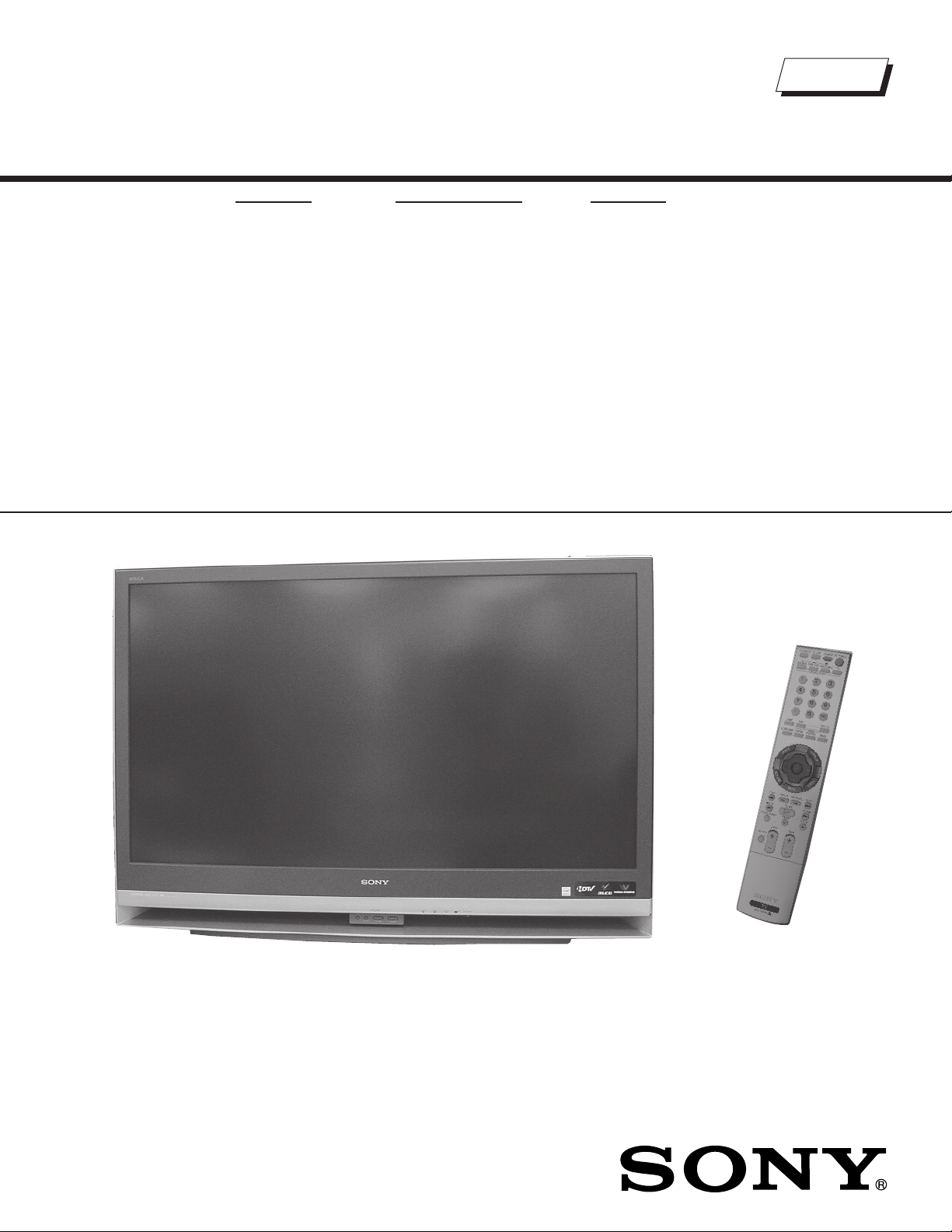
LCD PROJECTION TELEVISION
9-883-709-02
Self Diagnosis
Supported model
SERVICE MANUAL
MODEL NAME REMOTE COMMANDER DESTINATION
KDF-46E2000
KDF-46E2010
KDF-50E2000
KDF-50E2010
KDF-55E2000
KDF-55E2010
RM-YD010 US/CND
RM-YD010 MEXICO
RM-YD010 US/CND
RM-YD010 MEXICO
RM-YD010 US/CND
RM-YD010 MEXICO
LA-4
CHASSIS
9-883-709-02
KDF-50E2010 RM-YD010
LCD PROJECTION TELEVISION

KDF-46E2000/46E2010/50E2000/50E2010/55E2000/55E2010
TABLE OF CONTENTS
SECTION TITLE PAGE SECTION TITLE PAGE
Specifi cations ................................................................................. 4
Warnings and Cautions .................................................................. 6
Safety Check-Out ........................................................................... 7
Self-Diagnostic Function ................................................................. 8
SECTION 1: DISASSEMBLY ............................................................... 14
1-1. Overview .............................................................................. 14
1-2. Rear Cover Removal ............................................................ 15
1-3. Chassis Removal and Service Position ............................... 16
1-4. G Board Removal ................................................................. 16
1-5. B Block Assembly, A Block Assembly, Antenna,
U Board and K Board Removal ............................................ 17
1-6. Lamp Block Assembly and Optical Block Removal .............. 18
1-6-1. Lamp Connector and T2 Board Removal ................ 19
1-6-2. Lamp Driver Fan Removal ....................................... 20
1-7. HC Board Removal .............................................................. 21
1-8. HA Board and HB Board Removal ....................................... 21
1-9. Screen Frame Assebmly and Speaker Removal ................ 22
1-10. Mirror Assembly and Mirror Cover Assembly Removal ........ 23
Wire Dressing ....................................................................... 24
Caution Points ...................................................................... 42
SECTION 2: CIRCUIT ADJUSTMENTS .............................................. 49
2-1. Using the Remote Commander for Electrical Adjustments .. 49
2-2. Accessing Service Adjustment Mode ................................... 49
2-3. Viewing the Service Menus .................................................. 49
2-4. Using the Remote Commander to Change Service Data .... 50
2-4-1. Exiting Service Mode ............................................... 51
2-5. Verifying Service Data Changes .......................................... 51
2-6. Resetting Wega (User) Menu to Factory Defaults ............... 51
2-7. H/V Center Confi rmation and Adjustments .......................... 52
2-8. IRIS Adjustments .................................................................. 52
SECTION 3: DIAGRAMS ..................................................................... 53
3-1. Circuit Boards Location ........................................................ 53
3-2. Printed Wiring Boards and
Schematic Diagrams Information ......................................... 53
3-3. Signal Flow Block Diagram .................................................. 55
3-4. Schematics and Supporting Information .............................. 56
A Board Schematic Diagram ................................................ 56
B Board Schematic Diagram (1 of 11) .................................. 58
B Board Schematic Diagram (2 of 11) .................................. 59
B Board Schematic Diagram (3 of 11) .................................. 60
B Board Schematic Diagram (4 of 11) .................................. 61
B Board Schematic Diagram (5 of 11) .................................. 62
B Board Schematic Diagram (6 of 11) .................................. 63
B Board Schematic Diagram (7 of 11) .................................. 64
B Board Schematic Diagram (8 of 11) .................................. 65
B Board Schematic Diagram (9 of 11) .................................. 66
B Board Schematic Diagram (10 of 11) ................................ 67
B Board Schematic Diagram (11 of 11) ................................ 68
G Board Schematic Diagram (1 of 2) ................................... 70
G Board Schematic Diagram (2 of 2) ................................... 71
HA Board Schematic Diagram ............................................. 74
HB Board Schematic Diagram ............................................. 76
HC Board Schematic Diagram ............................................. 78
K Board Schematic Diagram ................................................ 80
S2 Board Schematic Diagram .............................................. 83
T1 Board Schematic Diagram .............................................. 86
T2 Board Schematic Diagram .............................................. 86
U Board Schematic Diagram ................................................ 91
3-5. Semiconductors ................................................................... 93
SECTION 4: EXPLODED VIEWS ........................................................ 94
4-1. Covers .................................................................................. 94
4-2. Chassis ................................................................................ 95
4-3. Optics Unit Block Assembly and Lamp Assembly ................ 96
KDF-46E2000/46E2010/50E2000/50E2010/55E2000/55E2010
SECTION 5: ELECTRICAL PARTS LIST ............................................ 97
APPENDIX A: REPLACING THE LAMP ............................................A-1
3

SPECIFICATIONS
p
)
KDF-46E2000/46E2010/50E2000/50E2010/55E2000/55E2010
Power Requirements
Power Consumption (W)
In Use (Max)
In Standby
Inputs/Outputs
120V AC, 60Hz
200W
Less than 0.8W
HDMI IN
2 Video - 1080i, 720p, 480p, 480i
1 Audio - Two channel linear PCM 32, 44.1 and 48 kHz,
16, 20, and 24 bit
Video (IN)
3 total (1 on side panel)
1Vp-p, 75ohms unbalanced, sync negative
S Video (IN)
1 total
Y: 1Vp-p, 75ohms unbalanced, sync negative
C: 0.286Vp-p (Burst signal), 75ohms
Audio (IN)
5 total (1 on side panel)
500 mVrms (100% modulation)
Impedance:47 kilo ohms
KDF-46E2000
KDF-46E2010
Component Video Input
3 (Y, P
Y: 1.0 Vp-p, 75 ohms unbalanced, sync negative
P
PR: 0.7 Vp-p, 75 ohms
Audio (VAR/FIX) Out
1 total
500 mVrms at the maximum volume setting
(Variable)
500 mVrms (Fixed)
Impedance (Output):2 kilo ohm
RF Input
2 total
Digital Audio Optical Output (PCM/Dolby Digital)
1 total
Optical Rectangular
) (1 on Side Panel)
B/CB
:
0.7 Vp-p, 75 ohms;
B
KDF-50E2000
KDF-50E2010
KDF-55E2000
KDF-55E2010
S
eaker Output(W
Dimensions (W x H x D)
mm 1096 x 766 x 382 mm 1184 x 827 x 408 mm 1301 x 907 x 442 mm
in
43
1/4
x 30
1/4
x 15
1/8
in 46
Mass
kg 27 kg 29.3 kg 34 kg
lbs 59 lbs 5 oz 64 lbs 7 oz 75 lbs
Trademark Information
As an ENERGY STAR® Partner, Sony
Corporation has determined that this product
meets the ENERGY STAR
®
guidelines for
energy efficiency.
ENERGY STAR
TruSurround XT, SRS and the ( )
®
is a U.S. registered mark.
®
symbol are
trademarks of SRS Labs, Inc. TruSurround XT
technology is incorporated under license from SRS Labs, Inc.
This TV is manufactured under license from Dolby
Laboratories. “Dolby” and the double-D symbol are
trademarks of Dolby Laboratories.
KDF-46E2000/50E2000/55E2000 KDF-46E2010/50E2010/55E2010
WEGA, Grand WEGA, WEGA GATE, Steady Sound,
Digital Reality Creation and CineMotion
are registered trademarks of Sony Corporation.
KDF-46E2000/46E2010/50E2000/50E2010/55E2000/55E2010
12W (L), 12W (R)
5/8
BBE and BBE Symbol are trademarks of BBE Sound,
Inc. and are licensed by BBE Sound, Inc. under U.S.
Patent No. 4,638,258 and 4,482,866.
(HDMI
Definition Multimedia Interface are trademarks or
registered trademarks of HDMI Licensing LLC.
Macintosh is a trademark licensed to Apple Computer, Inc.,
registered in the U.S.A and other countries.
“BRAVIA” and are trademarks of Sony Corporation.
x 32
5/8
x 16
1/8
in 51
1/4
x 35
3/4
x 17
1/2
in
This TV incorporates High-
™
) technology. HDMI, the HDMI logo and High-
Definition Multimedia Interface
Design and specifi cations are subject to change without notice.
4

Television system
American TV standard, NTSC
ATSC Compliant 8VSB, ATSC (8VSB terrestrial)
ANSI/SCTE 07 2000, QAM on cable
Channel coverage
Terrestrial 2-69/ Cable TV: 2-125 (analog)
Terrestrial 2-69/ Cable TV: 2-135 (digital)
Screen Size (measured diagonally)
46 inches (KDF-46E2000/46E2010 Only)
50 inches (KDF-50E2000/50E2010 Only)
55 inches (KDF-55E2000/55E2010 Only)
Antenna
75-ohm external antenna terminal for VHF/UHF
Projection System
3 LCD Panels, 1 lens projection system
LCD Panel
0.73 inch TFT LCD panel
(1,280 x 720 pixels)
KDF-46E2000/46E2010/50E2000/50E2010/55E2000/55E2010
Projection Lens
High Performance, large diameter hybrid lens F2.4
Lamp
100W, XL-2400 Ultra High Pressure Lamp
Supplied Accessories
Remote Commander RM-YD010
Two Size AA (R6) Batteries
Operating Instructions
Quick Setup Guide
Warranty Card
Product Registration Card
Optional Accessories
HDMI Cable
HDMI-to-DVI Cable
Component Video Cable
S VIDEO Cable
A/V Cable
Audio Cable
TV Stand:
SU-RG12S (KDF-46E2000/46E2010 Only)
SU-RG12L (KDF-50E2000/50E2010/55E2000/55E2010 Only)
KDF-46E2000/46E2010/50E2000/50E2010/55E2000/55E2010
5

KDF-46E2000/46E2010/50E2000/50E2010/55E2000/55E2010
WARNINGS AND CAUTIONS
CAUTION
These servicing instructions are for use by qualifi ed service personnel only. To reduce the risk of electric shock, do not perform any
servicing other than that contained in the operating instructions unless you are qualifi ed to do so.
WARNING!!
An isolation transformer should be used during any service to avoid possible shock hazard, because of live chassis. The chassis of
this receiver is directly connected to the AC power line.
! SAFETY-RELATED COMPONENT WARNING!!
Components identifi ed by shading and ! mark on the schematic diagrams, exploded views, and in the parts list are critical for safe
operation. Replace these components with Sony parts whose part numbers appear as shown in this manual or in supplements
published by Sony. Circuit adjustments that are critical for safe operation are identifi ed in this manual. Follow these procedures
whenever critical components are replaced or improper operation is suspected.
ATTENTION!!
Ces instructions de service sont à l’usage du personnel de service qualifi é seulement. Pour prévenir le risque de choc électrique, ne
pas faire l’entretien autre que celui contenu dans le Mode d’emploi à moins que vous soyez qualifi é faire ainsi.
Afi n d’eviter tout risque d’electrocution provenant d’un chássis sous tension, un transformateur d’isolement doit etre utilisé lors de tout
dépannage. Le chássis de ce récepteur est directement raccordé à l’alimentation du secteur.
! ATTENTION AUX COMPOSANTS RELATIFS A LA SECURITE!!
Les composants identifi es par une trame et par une marque ! sur les schemas de principe, les vues explosees et les listes de pieces
sont d’une importance critique pour la securite du fonctionnement. Ne les remplacer que par des composants Sony dont le numero
de piece est indique dans le present manuel ou dans des supplements publies par Sony. Les reglages de circuit dont l’importance
est critique pour la securite du fonctionnement sont identifi es dans le present manuel. Suivre ces procedures lors de chaque
remplacement de composants critiques, ou lorsqu’un mauvais fonctionnement suspecte.
KDF-46E2000/46E2010/50E2000/50E2010/55E2000/55E2010
6
SAFETY CHECK-OUT
KDF-46E2000/46E2010/50E2000/50E2010/55E2000/55E2010
After correcting the original service problem, perform the following
safety checks before releasing the set to the customer:
1. Check the area of your repair for unsoldered or poorly soldered
connections. Check the entire board surface for solder splashes and
bridges.
2. Check the interboard wiring to ensure that no wires are “pinched” or
touching high-wattage resistors.
3. Check that all control knobs, shields, covers, ground straps, and
mounting hardware have been replaced. Be absolutely certain that
you have replaced all the insulators.
4. Look for unauthorized replacement parts, particularly transistors,
that were installed during a previous repair. Point them out to the
customer and recommend their replacement.
5. Look for parts which, though functioning, show obvious signs of
deterioration. Point them out to the customer and recommend their
replacement.
6. Check the line cords for cracks and abrasion. Recommend the
replacement of any such line cord to the customer.
7. Check the B+ and HV to see if they are specifi ed values. Make sure
your instruments are accurate; be suspicious of your HV meter if sets
always have low HV.
8. Check the antenna terminals, metal trim, “metallized” knobs, screws,
and all other exposed metal parts for AC leakage. Check leakage as
described below.
Leakage Test
The AC leakage from any exposed metal part to earth ground and
from all exposed metal parts to any exposed metal part having a
return to chassis, must not exceed 0.5 mA (500 microamperes).
Leakage current can be measured by any one of three methods.
1. A commercial leakage tester, such as the Simpson 229 or RCA
WT-540A. Follow the manufacturers’ instructions to use these
instructions.
2. A battery-operated AC milliampmeter. The Data Precision 245
digital multimeter is suitable for this job.
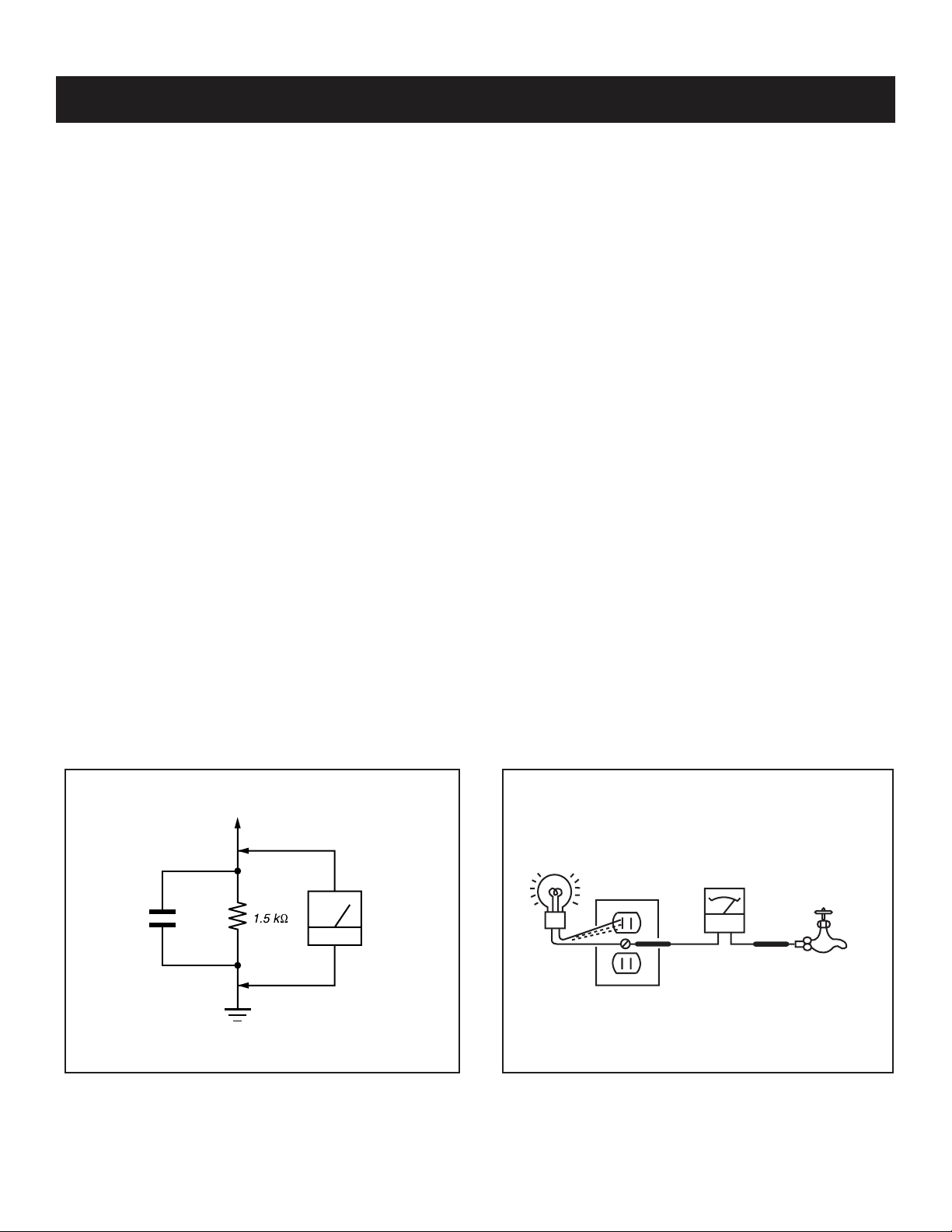
3. Measuring the voltage drop across a resistor by means of a VOM
or battery-operated AC voltmeter. The “limit” indication is 0.75
V, so analog meters must have an accurate low voltage scale.
The Simpson’s 250 and Sanwa SH-63TRD are examples of
passive VOMs that are suitable. Nearly all battery-operated digital
multimeters that have a 2 VAC range are suitable (see Figure A).
How to Find a Good Earth Ground
A cold-water pipe is a guaranteed earth ground; the cover-plate
retaining screw on most AC outlet boxes is also at earth ground. If the
retaining screw is to be used as your earth ground, verify that it is at
ground by measuring the resistance between it and a cold-water pipe
with an ohmmeter. The reading should be zero ohms.
If a cold-water pipe is not accessible, connect a 60- to 100-watt
trouble- light (not a neon lamp) between the hot side of the receptacle
and the retaining screw. Try both slots, if necessary, to locate the hot
side on the line; the lamp should light at normal brilliance if the screw
is at ground potential (see Figure B).
To Exposed Metal
Parts on Set
AC
0.15 µF
Earth Ground
Voltmeter
(0.75V)
Figure A. Using an AC voltmeter to check AC leakage. Figure B. Checking for earth ground.
KDF-46E2000/46E2010/50E2000/50E2010/55E2000/55E2010
Trouble Light
AC Outlet Box
Ohmmeter
Cold-water Pipe
7

KDF-46E2000/46E2010/50E2000/50E2010/55E2000/55E2010
SELF-DIAGNOSTIC FUNCTION
The units in this manual contain a self-diagnostic function. If an error occurs, the POWER/STANDBY will automatically begin to fl ash. The number of
times the LED fl ashes translates to a probable source of the problem. A defi nition of the POWER/STANDBY fl ash indicators is listed in the instruction
manual for the user’s knowledge and reference. If an error symptom is diffi cult to reproduced use the Remote Commander to display the record that is
stored at the internal NVM to specify the cause of the failure.
Diagnostic Test Indicators
When an error occurs, the POWER/STANDBY will fl ash a set number of times to indicate the possible cause of the problem. If there is more than
one error, the POWER/STANDBY will identify the fi rst of the problem areas. If the errors occur simultaneously, the one that corresponds to the fewest
fl ashes is identifi ed fi rst.
Results for all of the following diagnostic items are displayed on screen. (No error has occurred if the screen displays a “0”.)
Diagnosis Item
Temp error
Lamp cover /
Lamp position error
Fan error
Number of times
POWER/STANDBY
indicator blinks
2 times
3 times
4 times
Probable Cause/
Location
- Set temperture is high.
- Temp sensor connector
is not attached securely.
(CN110 on HB board,
CN160 on S2 board)
- Lamp cover is not
securely attached (T1 Bd)
-Lamp is not inserted
properly (T2 Bd)
- Fan 1-4 power is not
supplied. (B board)
-F
an connector is not
securely attached ..
-Fan caught wires or
harnesses.
- No Picture/No sound
- No Picture/No sound
- No Picture/No sound
Self Diagnosis
Detected symptoms
Supported model
Lamp driver error
LowB LVP
Thermal Fuse Open
LowB OVP
Lamp Error LAMP-LED flashes
5 times
6 times
8 times
-Lampdriverisfaulty.
- Check 10.5V audio IC
(B Board)
-B -10.5V is over voltage.
(B board)
- Lamp is burnt out.
- No Picture/No sound
- Relay click on/off
- No Picture/No sound
- No Picture/No sound
KDF-46E2000/46E2010/50E2000/50E2010/55E2000/55E2010
8

KDF-46E2000/46E2010/50E2000/50E2010/55E2000/55E2010
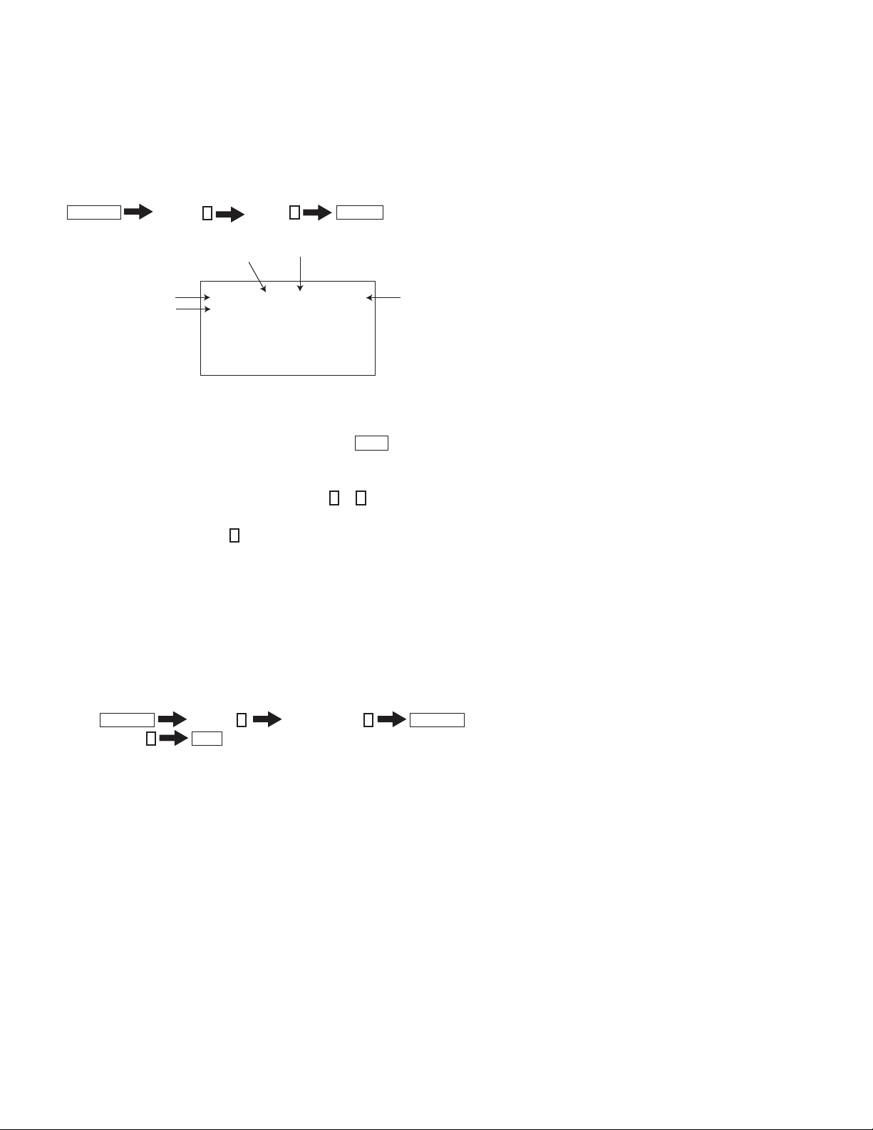
DISPLAY OF POWER/STANDBY OR LAMP LED FLASH COUNT
POWER/STANDBY
TIMER LAMP
PUSH OPEN
- One flash is not us ed for self- diagnosis.
Example
Diagnosis
Number of times LED Flash
Lamp cove r 3 times
Fan 4 times
LED ON : 0.3 se c
LED OFF : 0.3sec
Indicators
POWER
LED OFF
Screen
3.0 sec
LED OFF
3.0 sec
RELEASING THE POWER/STANDBY LED FLASH
Unplug the power cord from the outlet to temporarily stop the POWER/STANDBY lamp from fl ashing.
Self-Diagnostic Screen Display
For failures that are diffi cult to reproduce, or accompany occasional power off and/or picture mute, the Self-Diagnostic screen display is useful to
specify the cause.
VIEWING THE SELF-DIAGNOSTIC SCREEN
1. TV must be in standby mode. (Power off).
2. Press the following buttons on the Remote Commander within a second of each other:
DISPLAY
Channel
5
Volume -
NOTE: This differs from the method of accessing service mode which is Volume
Sample Self-Diagnostic Screen Display
SELF CHECK
1 : LAMP_ERR 0
2 : Lamp Temp Over 0
3:
LAMP_ COVER
FAN_ERR 1
4:
5 : LAMP_DRIVER
0
0
6 : LowB-ERROR 0
8 : D_OVP 0
POWER
+
"1" is displayed when an error is detected one or more times
"0" is displayed when no error has been detected
WDT101 : 0
Name: KDF-50E2000
Serial: XXXXXXX
NOTE: To refresh the Self Check menu when all the items are not displayed, press
JUMP
3. Proceed to Viewing the Self-Diagnostic Errors.
KDF-46E2000/46E2010/50E2000/50E2010/55E2000/55E2010
on the Remote Commander.
9
KDF-46E2000/46E2010/50E2000/50E2010/55E2000/55E2010
VIEWING THE SELF-DIAGNOSTIC ERRORS
The TV MICRO service menu contains a Log category that stores the errors. To view the fi rst error detected, display the SHUTDOWN_LOG1
Adjustment Item of the STATUS category. If other errors are detected, they are stored in the SHUTDOWN_LOG2 Adjustment Item of the STATUS
category.
1. TV must be in standby mode. (Power off).
2. Press the following buttons on the Remote Commander within a second of each other:
DISPLAY
Channel 5 Volume +
Item Number
POWER
Data Value
.
Category
Adjustment
Item
VERSION 0 0 SERVICE
VERS Wide Zoom Video 1
F/A: 00000000 00000000
CBA: 00000000 00000000
WSL: 480I
Service
Menu
3. Do one of the following:
a. If the TV MICRO Service Menu is displayed, proceed to the next step.
b. If the TV Micro Service Menu is not displayed, press
JUMP
on the Remote Commander until the TV MICRO service menu is displayed.
4. Do one of the following:
a. If the STATUS Category is displayed, proceed to the next step.
b. If the STATUS Category is not displayed, press 2 or 5 on the Remote Comman until the STATUS Category is displayed.
5. The SHUTDOWN_LOG1 Adjustment Item is the fi rst item of the STATUS Category and contains the fi rst error the set detected.
6. To view additional errors, press 1 until the SHUTDOWN_LOG2 Adjustment Item is displayed
7. After repairing the errors, proceed to Clearling the Self-Diagnostic Screen.
CLEARING THE SELF-DIAGNOSTIC SCREEN
The self-diagnostic results displayed on the screen are not cleared automatically, therefore you should always check the self-diagnostic screen during
repairs. When you have completed the repairs, clear the self-diagnostic screen to reset the results to “0”.
Note: The self-diagnostic function will not be able to detect any subsequent faults after completion of the repairs unless the Self-Diagnostic
result display is cleared to reset the results to “0”.
1. If the Self-Diagnostic screen is already displayed, proceed to step 3. If not, Power off (Set to Standby mode).
2. Press
3. Press Channel 8
DISPLAY
Channel
ENT
5
Sound Volume -
The status in the upper right corner changes to “WRITE”. When the operation is complete, the status returns to “SERVICE” and the Self-Diagnostic
screen is reset.
4. To exit the Self-Diagnostic screen, turn the power off.
POWER
KDF-46E2000/46E2010/50E2000/50E2010/55E2000/55E2010
10

SELF-DIAGNOSTIC FUNCTION OPERATION
KDF-46E2000/46E2010/50E2000/50E2010/55E2000/55E2010
KDF-46E2000/46E2010/50E2000/50E2010/55E2000/55E2010
11
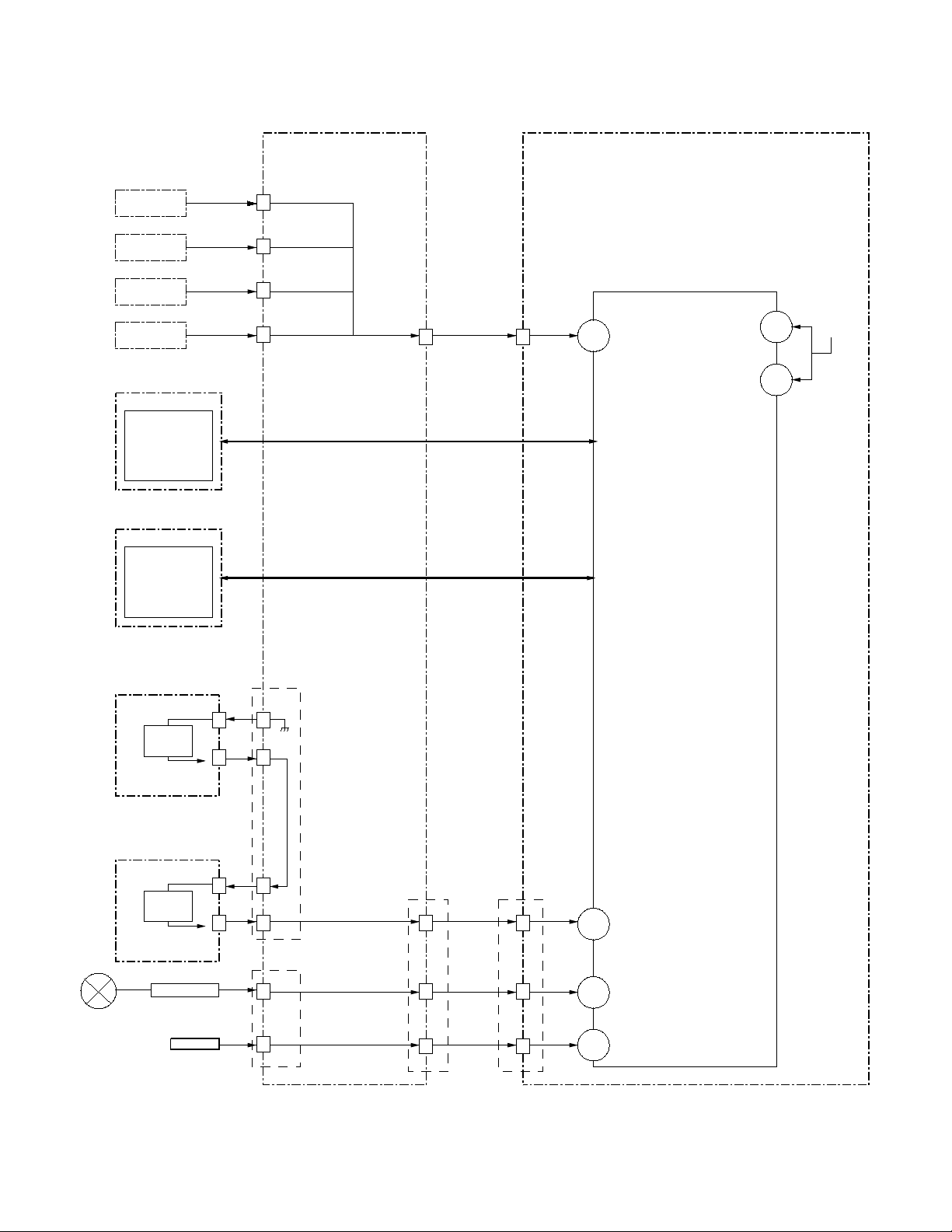
SELF-DIAGNOSTIC BLOCK DIAGRAM
G BOAR D B BOARD
CN6800
FAN 1
FAN 2
FAN 3
3
CN6805
3
CN6801
2
KDF-46E2000/46E2010/50E2000/50E2010/55E2000/55E2010
IC3002
TV Micro-computer
FAN 4
S2 BOARD
IC160
TEMP
SENSOR
HB BOARD
IC110
TEMP
SENSOR
T2 BOARD
SW
CN6802
2
CN6804
9
3
8
1
CN6904
I2C
I2C
2
CN3002
2
137
I_FAN_PROT
I2C
I2C
LB-ERROR
D_OVP
129
126
10.5V
T1 BOARD
10
1
CN6904
SW
LAMP DRIVER
HV-DET
11
3
CN6803
1
7
12
10
6
KDF-46E2000/46E2010/50E2000/50E2010/55E2000/55E2010
CN3002
12
10
6
150
151
152
I_LAMP_COVER
I_LAMP_PROT
I_HV_DET
12

KDF-46E2000/46E2010/50E2000/50E2010/55E2000/55E2010
READING LAMP AND PANEL TIME
The TV_Micro menu of the Service Menu displays the current lamp and
panel time of a set. The Lamp Hours and Panel Hours are shown in
hexadecimal format.
1. TV must be in standby mode. (Power off).
2. Press the following buttons on the Remote Commander within a
second of each other:
DISPLAY
One of the three Service Menu displays. (For more information
regarding the Service Menus, see
2-2. Accessing Service Adjustment Mode.)
3. To read the Lamp time, press 4 to display the TIME category and the
LMPH item.
Channel 5 Volume +
VERSION 00 SERVICE
VERS Wide Zoom Video 1
WSL: 480I
POWER
The screen displays:
TIME 0 0 SERVICE
LMPH
LMPH: 01H LMPL: A0H
Wide Zoom TV
.
RESETTING THE LAMP TIME
When replacing the lamp, use the following to reset the lamp time.
1. If the Self-Diagnostic screen is already displayed, proceed to step 4.
If not, Power off (Set to Standby mode).
2. Press
3. To access the Lamp reset, press 5 until the TIME category displays.
4. Press 1 until the RSET item displays.
5. To reset the Lamp time, press 3 to change the data value to 1.
6. Press
DISPLAY
POWER
MUTING
Channel
TIME 0 0 SERVICE
RSET
TIME 0 1 SERVICE
RSET
TIME 0 1 WRITE
RSET
Wide Zoom TV
Wide Zoom TV
ENT
Wide Zoom TV
5
Sound Volume -
to write the change into memory.
Total hours 256 Total hours 160
Total LAMP TIME is 416 hours
4. To read the Panel time, press 4 to display the PHLH item.
The screen displays:
TIME 0 0 SERVICE
PNLH
PNLH: 01H PNLL: A0H
Wide Zoom TV
Total hours 256 Total hours 160
Total PANEL TIME is 416 hours
5. Do one of the following:
a. If you have replaced the lamp, proceed to step 4 of “Resetting the
Lamp Time”.
b. If you have not replaced the lamp, turn off the set by pressing
POWER
6. To verify the Lamp has been reset press 5 until the TIME category
displays, and then press 1 until the LMPH item displays.
NOTE: You cannot reset the Panel time with the Service menu.
EXITING SERVICE MODE
After completing the changes, exit service mode by turning off the set
using the Remote Commander or the power switch.
NOTE: After exiting service mode wait 2 minutes before restarting
the set to allow the fans to shut down properly.
KDF-46E2000/46E2010/50E2000/50E2010/55E2000/55E2010
13
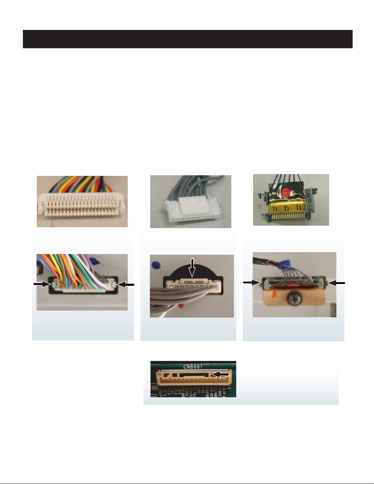
1-1. OVERVIEW
TOOLS NEEDED
Long Phillips Screwdriver
Needle Nose Pliers
Small Flathead Screwdriver or Jewelers Screwdriver
The connectors in the MIX5 chassis have been redesigned to ensure they are securely fasten to the boards. Please review the
illustrations below.
Use caution not to rock the Type 2 or Type 3 connectors when removing or reinstalling to avoid breaking the solder leads off the
Printed Circuit Boards.
KDF-46E2000/46E2010/50E2000/50E2010/55E2000/55E2010
SECTION 1: DISASSEMBLY
TYPE 1
LIFT ONE SIDE AT A TIME
BY PUSHING TAB IN WITH
SMALL SCREWDRIVER
TYPE 2
SQUEEZE DOWN ON
TAB TO RELEASE
TYPE 3
SQUEEZE LOCKING TAB
TOWARDS CONNECTOR
BEFORE PULLING FREE
CAUTION! IF THE TYPE 2 FEMALE
CONNECTOR HAS A SLOT (AS SHOWN)
MAKE SURE THE LOCK TAB SEATS INSIDE
THIS SLOT.
KDF-46E2000/46E2010/50E2000/50E2010/55E2000/55E2010
14

1-2. REAR COVER REMOVAL
1
Pull down the claw to release the Lamp Door
2
Remove the Lamp Door
3
Remove 13 screws (+BVTP2 4X16)
to remove the Rear Cover
1
Lamp door
KDF-46E2000/46E2010/50E2000/50E2010/55E2000/55E2010
3
When reassembling the rear cover, be sure to securely lock
the lamp door to avoid a lamp cover failure warning.
2
Lamp door
Lamp door
Turn the handle until it is in
the CLOSE position
KDF-46E2000/46E2010/50E2000/50E2010/55E2000/55E2010
15

1-3. CHASSIS REMOVAL AND SERVICE POSITION
1
Remove 2 screws to release the Left Stay
2
Disconnect CN8400 from U Board
3
Disconnect CN2500 from K Board
4
Release wires from purse locks
5
Gently pull chassis out towards the right of the TV to access
connectors on B Block Assembly.
6
Disconnect CN308 and CN3750 on B Block Assembly
7
Release connectors from Wire Holders
8
Remove 4 screws to release the G Board
9
Remove 6 screws to detach Metal Shield from G Board
2
KDF-46E2000/46E2010/50E2000/50E2010/55E2000/55E2010
4
1
3
9
8
7
5
6
1-4. G BOARD REMOVAL
Using the picture above as a reference, disconnect CN6018,
CN6801, CN6804, CN6803, CN6800, CN6805, CN6900,
CN6901, CN6009, CN6002, CN6904, and CN6010.
KDF-46E2000/46E2010/50E2000/50E2010/55E2000/55E2010
16

1-5. B BLOCK ASSEMBLY, A BLOCK ASSEMBLY, ANTENNA,
U BOARD AND K BOARD REMOVAL
1
1
Remove 6 screws and 2 hexagon washers
Terminal Bracket from the U Board.
On the U Board, disconnect CN8400 then using a fl at
head screw driver gently release the CN3006 connector
from the B Board to remove the U Board.
2
Disconnect the coaxial cable to release the antenna
switch. Remove 3 screws then gently lift the A Block
Assembly up to disconnect CN1002 from the B Block
Assembly.
3
Using caution remove the LVDS cable from the B Board,
then remove 1 screw (connecting the B Block Assy & K
Board to the Main Bracket) and lift up on the tab of the
Main Bracket to release the B Block Assembly.
4
Using tweezers gently pinch the fan dampers to release
the fan.
5
On the K Board, disconnect CN2502 then remove 1
screw to release the K Board. Gently pull the K Board out
of the Main Bracket.
to
release the
U Board
B Block Assembly
5
K Board
KDF-46E2000/46E2010/50E2000/50E2010/55E2000/55E2010
2
A Block Assembly
LVDS Connection
3
4
KDF-46E2000/46E2010/50E2000/50E2010/55E2000/55E2010
17

KDF-46E2000/46E2010/50E2000/50E2010/55E2000/55E2010
1-6. LAMP BLOCK ASSEMBLY AND OPTICAL BLOCK REMOVAL
Note: Remove the Lamp door and Lamp before removing the Lamp Block Assembly
(See “Replacing the Lamp” in the Appendix section of this service manual.)
1
Remove 2 screws to release the Right Stay.
2
Disconnect CN150 T1 Board
3
Disconnect CN155 T2 Board
4
Disconnect the Termal Fuse connector.
5
Disconnect CN160 S2 Board
6
Remove 2 screws then pull out the fan cover.
7
Turn the fan cover over to remove the T1 Board and S2
Board.
8
Using caution remove the LVDS cable and 2 screws.
9
Remove 2 screws to release the Lamp Block Assembly and
the Optical Block assembly from the cabinet.
0
Gently pull the Lamp Block Assembly and the Optical Block
Assembly out of the cabinet.
11
Turn the assemblies around 180 degrees and release the
high voltage lead from the purse lock.
2
1
6
3
4
5
T1Board
7
9
S2 Board
8
0
KDF-46E2000/46E2010/50E2000/50E2010/55E2000/55E2010
11
18

1-6-1. LAMP CONNECTOR AND T2 BOARD REMOVAL
1
Pull retaining clip outward to release and drop the high
voltage connector and the T2 Bracket.
2
Separate the HV Connector from the bracket
3
Remove 1 screw to release the T2 Board.
1
KDF-46E2000/46E2010/50E2000/50E2010/55E2000/55E2010
2
1
3
KDF-46E2000/46E2010/50E2000/50E2010/55E2000/55E2010
19

KDF-46E2000/46E2010/50E2000/50E2010/55E2000/55E2010
KDF-46E2000/46E2010/50E2000/50E2010/55E2000/55E2010
20
Lamp duct cover
Note position of wires
Note: Watch for
fan grommets
NOTE:
Reinsert the
fan grommets
when replacing
the fan
2
3
4
5
6
1
1
From the inside of the assembly, release the 3 claws
securing the fan duct, then remove the fan duct by grasping
as shown.
Remove 1 screw.
Release 3 clips to detach cover.
Remove Fan.
Release wire from wire holders.
Remove 2 screws.
2
3
4
5
6

1-7. HC BOARD REMOVAL
1
Remove 2 screws to detach the H2 Bracket.
2
Disconnect connector.
3
Remove 2 screws.
4
Lift out to remove HC Board.
3
KDF-46E2000/46E2010/50E2000/50E2010/55E2000/55E2010
1
4
1-8. HA BOARD AND HB BOARD REMOVAL
1
Remove 2 screws from inside the front panel.
2
Using a screwdriver, gently push through the hole to
release the speaker grill.
3
Firmly pull on the speaker grill to detach from the cabinet.
4
Disconnect CN7000 and remove 2 screws to release the
HA Board
5
Disconnect CN7020 and remove 2 screws to release the
HB Board
2
1
HA Board
4
HB Board
5
3
KDF-46E2000/46E2010/50E2000/50E2010/55E2000/55E2010
21

KDF-46E2000/46E2010/50E2000/50E2010/55E2000/55E2010
1-9. SCREEN FRAME ASSEBMLY AND SPEAKER REMOVAL
CAUTION: When removing the Screen Frame Assembly be sure to clean the Mirror and Diffusion Plate(s) to remove any dust particles.
1
Release the wire harness from the purse locks.
2
Disconnect the CN2500 from the K Board.
3
Remove 15 screws to detach the Mirror Cover Assembly
from the Screen Frame Assembly.
4
Remove 4 screws to detach the Screen Frame Assembly
from the front bezel.
5
Gently pull the Screen Frame Assembly forward.
6
Remove 20 screws from the screen frame to release the
disfussion plates. Be sure to keep the retaining brackets.
7
To remove the speakers, remove 2 screws and release the
speaker wires.
1
2
5
3
4
6
KDF-46E2000/46E2010/50E2000/50E2010/55E2000/55E2010
7
7
22

KDF-46E2000/46E2010/50E2000/50E2010/55E2000/55E2010
1-10. MIRROR ASSEMBLY AND MIRROR COVER ASSEMBLY REMOVAL
CAUTION: When removing the Mirror Cover Assembly be sure to clean the Mirror and Diffusion Plate(s) to remove any dust particles.
1
Remove 4 screws to release the 2 top mirror brackets.
2
Remove 3 screws to release the mirror holders (46” & 50”
models only)
3
Using caution gently lift the mirror up and out of the mirror
cover. (Slide the mirror up and to one side on the 55” model
to release it from the mirror holders.)
4
Remove 4 screws to detach the front of the Mirror Cover
Assembly from the cabinet.
5
Remove 2 screws from back of the cover and then lift the
Mirror Cover Assembly off of the cabinet.
3
1
2
4
5
KDF-46E2000/46E2010/50E2000/50E2010/55E2000/55E2010
23

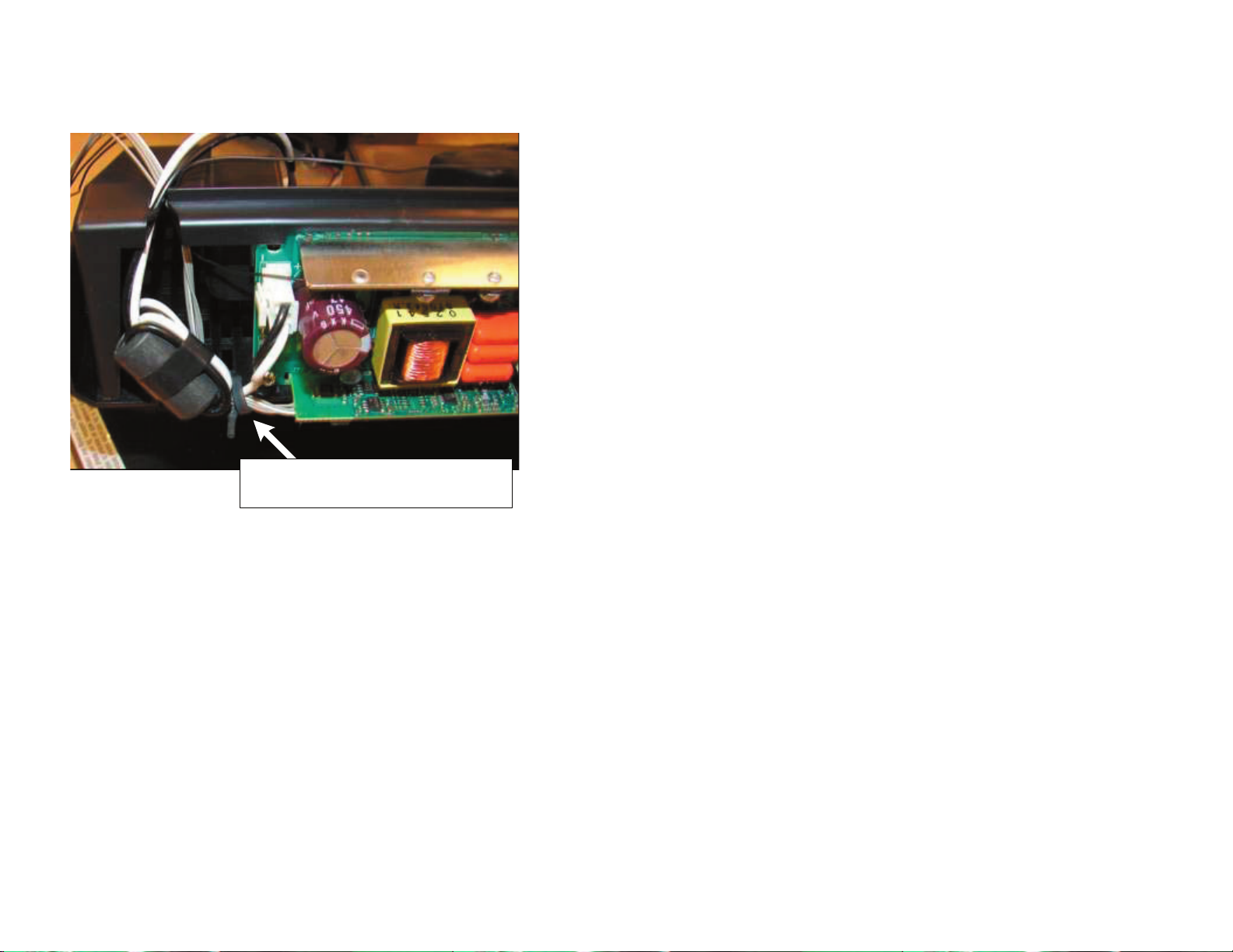
WIRE DRESSING
BALLAST WIRE DRESSING
“Top” Lead
Dress Lamp Driver Leads as shown
below to wire holders.
Dress "Bottom" Lamp Driver Lead as
shown to wire holder on Duct Block Assy
“Bottom”
Lead
KDF-46E2000/46E2010/50E2000/50E2010/55E2000/55E2010
After Installing Duct Block assy to
Optical Block Dress “TOP” Lamp Lead
to Purse Lock on [C] Shield
KDF-46E2000/46E2010/50E2000/50E2010/55E2000/55E2010
1-910-024-31 Connector Assy should be
dressed around Heat Sink and around Duct
Block Cover as shown above.
24
BALLAST WIRE DRESSING (CONTINUED)
1-910-024-31 Connector Assy should be
dressed around Heat Sink and around Duct
Block Cover as shown above.
KDF-46E2000/46E2010/50E2000/50E2010/55E2000/55E2010
KDF-46E2000/46E2010/50E2000/50E2010/55E2000/55E2010
25

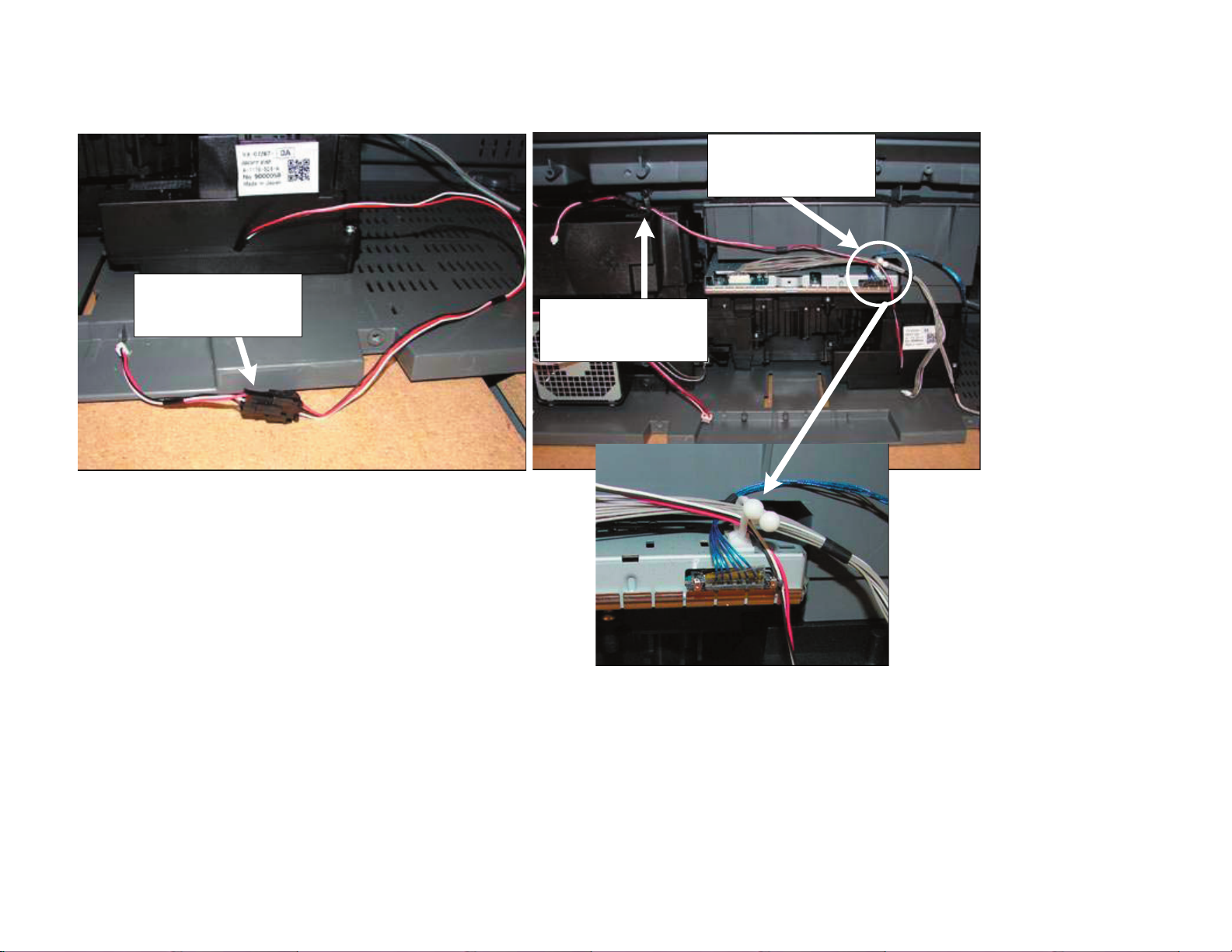
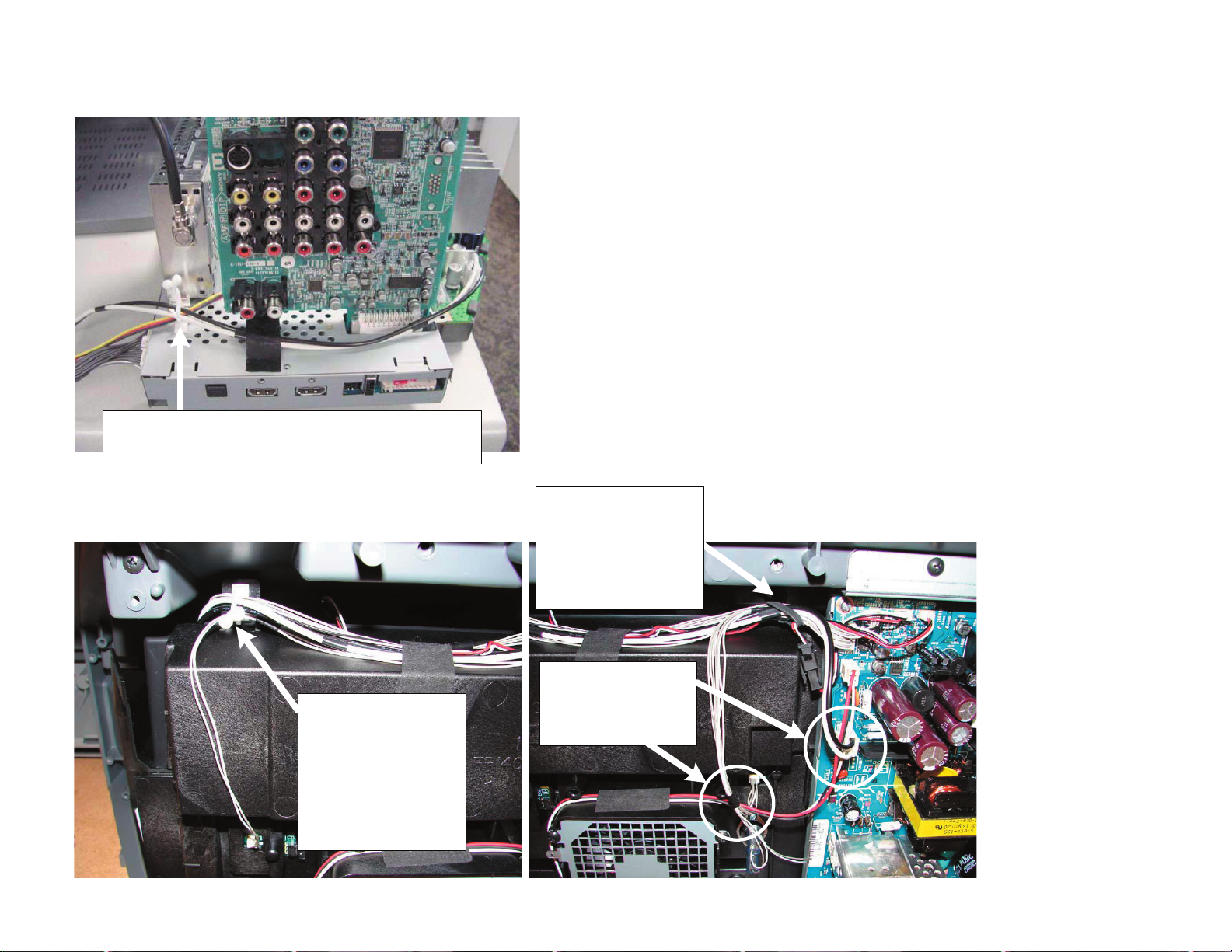
BOTTOM BLOCK WIRE DRESSING
Before installing chassis
Dress CN3004[B],
CN8400[U], and CN3008[B]
to purse lock on bottom
block as shown.
Loop Video 2 Connector
before installing into Purse
Lock as shown to avoid
Connector assy from
Touching [K] Board Heat
Sink.
ONLY FOR 46" and 50"
models
KDF-46E2000/46E2010/50E2000/50E2010/55E2000/55E2010
KDF-46E2000/46E2010/50E2000/50E2010/55E2000/55E2010
Install Ferrite Clamp
154383011 to the following
Connector Assys
1. Speaker Conn Assy
2. HA/HB Conn Assy
3. HC Conn Assy
26
C BLOCK WIRE DRESSING
Install Conn Assy
1-910-024-21 to "FAN1"
Optical Block Fan.
Route Optical Block Fan
to Wire Holder to avoid
being “Pinched” when [G]
Shield is installed
Dress 15P CN9000 [C]
LVDS Connector and Fan
Connector to Purse Lock
on [C] Shield
KDF-46E2000/46E2010/50E2000/50E2010/55E2000/55E2010
KDF-46E2000/46E2010/50E2000/50E2010/55E2000/55E2010
27
CHASSIS WIRE DRESSING
Dress [B] Block Fan and [K] Board Connector Assy to Purse
Lock on [B] Block as shown above.
KDF-46E2000/46E2010/50E2000/50E2010/55E2000/55E2010
DUCT BLOCK ASSEMBLY WIRE DRESSING
Dress the following
Connector Assys to
Purse Lock on Duct Block
Assy :
1. CN150 [T1]
2. X1 (Ballast)
3. X2 (Ballast)
Note:
Duct Block Fan is not
installed to Purse Lock
KDF-46E2000/46E2010/50E2000/50E2010/55E2000/55E2010
Dress the following
Connector Assys to Wire
Holder on Bottom Block:
1. 1-910-024-29
2. X1 (Ballast)
3. X2 (Ballast)
4. Duct Block Assy Fan
5. Optical Block Fan
Route Lamp Fan
“inside” of 1-910-024-29
and Inside of X2 (Ballast
Power)
28

G BOARD WIRE DRESSING
KDF-46E2000/46E2010/50E2000/50E2010/55E2000/55E2010
1
G-Board Wire Pin Holders Instructions. There are (3)
wire pin Holders on the [G] board. See below to see
which wires are dressed to each wire pin holder
2
1. LVDS and 8P CN6009[G]
2. LVDS, 8P CN6009, and 7P CN3004[B]
3. LVDS and 7P CN3004[B]
Ensure wires are dressed to the side of the G Board
as shown.
3
KDF-46E2000/46E2010/50E2000/50E2010/55E2000/55E2010
Install Purse Lock
404928101 PURSE LOCK (DIA.11)
Purse lock should hold the following:
32P Conn Assy [G] to [B]
3P Conn Assy [G] to [K]
3P Conn Assy [G] to ANT SWT
3P Conn Assy [G] to B-Blk FAN
After installing Purse Lock ensure “open” end is
facing towards the front of the set.
29

OPTICAL BLOCK ASSEMBLY WIRE DRESSING
ROUTE IRS CONNECTOR AS SHOWN
KDF-46E2000/46E2010/50E2000/50E2010/55E2000/55E2010
APPLY HIMELONE TAPE TO SECURE IRIS CONNECTOR AS SHOWN ABOVE.
APPLY TAPE SO THAT THE CONNECTOR ASSEMBLY WILL NOT BE IN SHADED AREA ABOVE.
APPLY HIMELONE TAPE AS SHOWN ABOVE
AND DRESS IRIS CONNECTOR ASSY
TO WIRE HOLDER AS SHOWN BELOW
KDF-46E2000/46E2010/50E2000/50E2010/55E2000/55E2010
IF CONNECTOR ASSEMBLY IS IN THE SHADED
ARER IT WILL GET PINCHED BETWEEN THE
OPTICAL BLOCK ASSEMBLY AND THE BOTTOM
BLOCK ASSEMBLY WHEN INSTALLED.
30
 Loading...