

Page 1

4-098-430-11 (1)
Flat Panel Color TV KDE42XBR950/KDE50XBR950/KDE61XBR950
Flat Panel Color TV
Operating Instructions
KDE42XBR950
KDE50XBR950
KDE61XBR950
2003 Sony Corporation
Page 2

Page 3

WARNING
To reduce the risk of fire or shock hazard, do not expose the TV to rain or
moisture.
CAUTION
RISK OF ELECTRIC SHOCK
DO NOT OPEN
ATTENTION
RISQUE DE CHOC ELECTRIQUE,
NE PAS OUVRIR
PRECAUCION
RIESGO DE CHOQUE ELECTRICO
NO ABRIR
CAUTION: TO REDUCE THE RISK OF ELECTRIC SHOCK,
DO NOT REMOVE COVER (OR BACK).
NO USER-SERVICEABLE PARTS INSIDE.
REFER SERVICING TO QUALIFIED SERVICE PERSONNEL.
This symbol is intended to alert the user to the presence
of uninsulated “dangerous voltage” within the
product’s enclosure that may be of sufficient
magnitude to constitute a risk of electric shock to
persons.
This symbol is intended to alert the user to the presence
of important operating and maintenance (servicing)
instructions in the literature accompanying the
appliance.
Note on Caption Vision
This television receiver provides display of television closed captioning in
accordance with §15.119 of the FCC rules.
Note to CATV System Installer
This reminder is provided to call the CATV system installer’s attention to
Article 820-40 of the National Electrical Code (NEC) that provides
guidelines for proper grounding and, in particular, specifies that the cable
ground shall be connected to the grounding system of the building, as close
to the point of cable entry as practical.
Use of this television receiver for other than private viewing of programs
broadcast on UHF or VHF or transmitted by cable companies for the use
of the general public may require authorization from the broadcaster/cable
company and/or program owner.
NOTIFICATION
This equipment has been tested and found to comply with the limits for a
Class B digital device pursuant to Part 15 of the FCC Rules. Thes e limits
are designed to provide reasonable protection against harmful interference
in a residential installation. This equipment generates, uses, and can radiate
radio frequency energy and, if not installed and used in accordance with the
instructions, may cause harmful interference with radio communications.
However, there is no guarantee that interference will not occur in a
particular installation. If this equipment does cause harmful interference to
radio or television reception, which can be determined by turning the
equipment off and on, the user is encouraged to try to correct the
interference by one or more of the following measures:
s Reorient or relocate the receiving antennas.
s Increase the separation between the equipment and receiver.
s Connect the equipment into an outlet on a circuit different from that
to which the receiver is connected.
s Consult the dealer or an experienced radio/TV technician for help.
You are cautioned that any changes or modifications not expressly
approved in this manual could void your authority to operate this
equipment.
CAUTION
To prevent electric shock, do not use this polarized AC plug with an
extension cord, receptacle or other outlet unless the blades can be fully
inserted to prevent blade exposure.
CAUTION
When using TV games, computers, and similar products with your TV,
or viewing a TV station whose logo always stays on the screen, keep
the brightness and contrast functions at low settings. If a fixed
(non-moving) pattern such as a station logo is left on the screen for
long periods of time, especially at a high brightness or contrast setting,
the image can be permanently imprinted onto the screen. These types
of imprints are not covered by your warranty.
Owner’s Record
The model and serial numbers are located at the rear of the TV, below the
Sony logo, on the sticker, and also on the TV box (white label). Record
these numbers in the spaces provided below. Refer to them whenever you
call upon your Sony dealer regarding this product.
Model No.________________ ________________
Serial No. ________________________________
Safety
s Operate the TV only on 120 V AC.
s The plug is designed, for safety purposes, to fit into the wall outlet
only one way. If you are unable to insert the plug fully into the outlet,
contact your dealer.
s If any liquid or solid object should fall inside the cabinet, unplug the
TV immediately and have it checked by qualified service personnel
before operating it further.
s If you will not be using the TV for several days, disconnect the
power by pulling the plug itself. Never pull on the cord.
s For details concerning safety precautions, see “Important
Safeguards” on page 3.
Important Notice
s When used at an altitude of greater than 2400m or 7872feet (air
pressure less than 750hPa), this Plasma Display Panel may generate
a low buzzing sound as a result of the difference between the interior
and exterior air pressure of the panels. This is not c onsidered a defect
and is not covered under by the Limited Warranty.
1
Page 4

Installing
s To prevent internal heat buildup, do not block the ventilation
openings.
s Do not install the TV in a hot or humid place, or in a place subject to
excessive dust or mechanical vibration.
s Avoid operating the TV at temperatures below 5°C (41°F).
s If the TV is transported directly from a cold to a warm location, or if
the room temperature changes suddenly, the picture may be blurred
or show poor color due to moisture condensation. In this case, please
wait a few hours to let the moisture evaporate before turning on the
TV.
s To obtain the best picture, do not expose the screen to direct
illumination or direct sunlight. It is recommended to use spot
lighting directed down from the ceiling or to cover the windows that
face the screen with opaque drapery. It is desirable to install the TV
in a room where the floor and walls are not of a reflective material.
As an ENERGY STAR® Partner, Sony
Corporation has determined that this product
meets the E
energy efficiency.
NERGY STAR
®
guidelines for
CAUTION
The following SONY appliance(s) for use only with the following TV
STAND or WALL-HANGING RACK UNIT. Use with other TV STAND
or WALL-HANGING RACK UNIT is capable of resulting in instability
causing possible injury.
SONY APPLIANCE MODEL NO.
KDE42XBR950 (PDM-4210)
KDE50XBR950 (PDM-5010)
KDE61XBR950 (PDM-6110)
SONY TABLE TOP STAND MODEL NO.
SU-P42T2 (for PDM-4210)
SU-P50T2 (for PDM-5010/6110)
SONY WALL-MOUNT BRACKET MODEL NO.
SU-PW2 (for PDM-4210/5010/6110)
NERGY STAR
E
®
is a U.S. registered mark.
CAUTION
How to reduce the risk of “Image Retention” on your TV
Bright, stationary images such as TV station logos displayed on your
TV can cause permanent damage to your TV, resulting in retention of
the image in the picture. Please take the following steps to reduce the
risk of causing image retention:
View a variety of program sources or programming material.
Image retention can occur when bright stationary images such as TV
station logos are viewed. Changing the program material viewed
reduces the possibility that a single image will become imprinted on
the picture tubes in your TV.
When viewing programs with stationary images, adjust the picture
setting to reduce the “Picture” and “Brightness” levels. Image
retention is accelerated by higher “Brightness” and higher “Picture”
settings.
Please see page 96 for instructions on adjusting picture settings.
This will help you reduce the risk of causing image retention.
IMAGE RETENTION IS NOT COVERED BY YOUR WARRANTY
SONY FLOATING STAND MODEL NO.
SU-PF1 (for PDM-4210/5010)
SU-PF1L (for PDM-611 0)
To Customers
Sufficient expertise is required for installing the specified product. Be sure
to subcontract the installation to Sony dealers or contractors and pay
adequate attention to safety during the installation.
Trademark Information
TruSurround, SRS and the symbol are trademarks of SRS Labs, Inc.
TruSurround technology is incorporated under license from SRS Labs, Inc.
BBE and BBE Symbol are trademarks of BBE Sound, Inc. and are licensed
by BBE Sound, Inc. under U.S. Patent No. 4,638,258 and 4,482,866.
Steady Sound, Digital Reality Creation, Caption Vision, CineMotion,
Memory Stick, and Twin View are registered trademarks of Sony
Corporation. ClearEdge VM, HD Detailer, and Uniform Brightness Screen
are trademarks of Sony Corporation.
2
Page 5

Important
Safeguards
Before using your TV, please read these instructions completely, and keep
this manual for future reference.
Carefully observe and comply with all warnings, cautions and instructions
placed on the set or described in the operating instructions or service
manual.
WARNING
To guard against injury, the following basic safety precautions should be
observed in the installation, use and servicing of the set.
Use
Power Sources
This set should be operated only from the type of
power source indicated on the serial/model plate.
If you are not sure of the type of electrical power
supplied to your home, consult your dealer or local
power company. For those sets designed to operate
from battery power, refer to the operating
instructions.
Grounding or Polarization
This set is equipped with a polarized AC power cord plug (a plug having
one blade wider than the other), or with a three-wire grounding type plug
(a plug having a third pin for grounding).Follow the instructions below:
For the set with a polarized AC power cord plug
This plug will fit into the power outlet only one way.
This is a safety feature. If you are unable to insert the
plug fully into the outlet, try reversing the plug.
If the plug still fails to fit, contact your electrician to
have a suitable outlet installed. Do not defeat the safety purpose of the
polarized plug by forcing it in.
Wall outlet
Do not use a poor fitting outlet.
Insert the plug fully into the outlet. If it is loose, it
may cause arcing and result in fire.
Contact your electrician to have the outlet changed.
Wiring
Unplug the AC power cord when wiring cables.
Be sure to unplug the AC power cord for your safety, when hooking up.
Moisture
Do not touch the AC power cord with a wet hand.
If you plug/unplug the AC power cord with a wet
hand, it may cause electric shock.
Cleaning
Clean the AC power plug regularly.
If the plug is covered with dust and it picks up
moisture, its insulation may deteriorate and result in
fire. Unplug the AC power plug and clean it
regularly.
For the set with a three-wire grounding type AC
plug
This plug will only fit into a grounding-type power
outlet. This is a safety feature. If you are unable to
insert the plug into the outlet, contact your electrician
to have a suitable outlet installed. Do not defeat the
safety purpose of the grounding plug.
Overloading
Do not overload wall outlets, extension cords or
convenience receptacles beyond their capacity, since
this can result in fire or electric shock.
Always turn the set off when it is not being used.
When the set is left unattended and unused for long
periods of time, unplug it from the wall outlet as a
precaution against the possibility of an internal
malfunction that could create a fire hazard.
If a snapping or popping sound from a TV set is
continuous or frequent while the TV is operating,
unplug the TV and consult your dealer or service
technician. It is normal for some TV sets to make
occasional snapping or popping sounds, particularly
when being turned on or off.
AC power cord and display interface cable
If you damage the AC power cord or display interface cable, it may result
in fire or electric shock.
s Do not pinch, bend, or twist the cable excessively. The core lines
may be bared and cut, and cause short-circuit, resulting in fire or
electric shock.
s Do not convert or damage the AC power cord or display interface
cable.
s Do not put anything heavy on the AC power cord or display interface
cable. Do not pull the AC power cord or display cable.
s Keep the AC power cord or display interface cable away from heat
sources.
s Be sure to grasp the plug when disconnecting the AC power cord.
s Refer to the operating instructions when disconnecting the display
interface cable.
If the AC power cord or display interface cable is damaged, stop using it
and ask your dealer or Sony service center to exchange it.
Cleaning
Unplug the AC power cord when cleaning this unit. If not, it may result in
electric shock.
Object and Liquid Entry
Never push objects of any kind into the set through the
cabinet slots as they may touch dangerous voltage
points or short out parts that could result in a fire or
electric shock. Never spill liquid of any kind on the
set.
(Continued)
3
Page 6

Ventilation holes
Do not insert anything in the ventilation holes. If
metal or something flammable enters, it may result in
fire or electric shock.
Cleaning
Clean the cabinet of the TV with a dry soft cloth. To
remove dust from the screen, wipe it gently with a soft
cloth. Stubborn stains may be removed with a cloth
slightly dampened with a solution of mild soap and
warm water. Never use strong solvents such as thinner
or benzine for cleaning.
If the picture becomes dark after using the TV for a long period of time, it
may be necessary to clean the inside of the TV. Consult qualified service
personnel.
Attachments
Do not use attachments not recommended by the
manufacturer, as they may cause hazards.
Installation
When installing the display unit on the wall, be sure to
have assemblers install and keep away from the unit.
If a person other than the assemblers install the display
unit on the wall using a wall mount unit, the unit may
fall and cause serious injury when an earthquake
occurs or when the unit is not installed securely.
Carrying
Carrying the set requires two or more people.
If you carry the set in a manner other than that
specified, it may drop and a serious injury may be
caused. Be sure two or more people carry the set.
When transporting, do not subject the set to shocks or
vibration excessive force. The set may fall and damage the set, causing
serious injury.
AC power cord
Unplug the AC power cord when moving the set.
Do not move the set with the AC power cord plugged in. It may damage
the AC power cord and result in fire or electric shock.
Medical institution
Do not place this unit in a place where medical
equipment is in use.
It may cause malfunction of medical instrume nts .
Water and Moisture
Do not use power-line operated sets near
water — for example, near a bathtub, washbowl,
kitchen sink, or laundry tub, in a wet basement, or
near a swimming pool, etc. It may result in fire or
electric shock.
Accessories
Do not place the set on an unstable cart, stand, table or
shelf. The set may fall, causing serious injury to a child
or an adult and serious damage to the set. Use only a
cart or stand recommended by Sony for the specific
model of TV. No part of the TV set should overhang
any edge of the TV cart or stand; any overhanging edge
is a safety hazard. An appliance and cart combination
should be moved with care. Quick stops, excessive
force, and uneven surfaces may cause the appliance and
cart combination to overturn.
Moisture and flammable objects
s Do not let this unit get wet. Never spill liquid of any kind on the unit.
If any liquid or solid object does fall through, do not operate the unit.
It may result in electric shock or damage to the unit. Have it checked
immediately by qualified personnel.
s To prevent fire, keep inflammable objects or naked lights (e.g.
candles) away from the set.
Dispose of used batteries
To preserve our environment, dispose the used batteries according to your
local laws or regulations.
Installation and moving
Optional accessories
Observe the following when installing the display unit
using a stand or wall mount unit. If not, the unit may fall
and cause serious injury.
s Be sure to follow the operating instructions
supplied with your stand when installing the unit.
s Be sure to attach the brackets supplied with your
stand.
Protruding location
Do not install the display unit in protruding locations. If you install the unit
in the following locations, injury may result.
s Do not install the unit in a location where the unit protrudes, such as
pillars.
s Do not install the unit in a location that may cause facial injury.
Oils
Do not install this unit in restaurants where oily vapours occur. Dust
absorbing oil may enter into the unit and damage the unit.
Corrosion
If you use this unit near the seashore, salt may corrode metal parts of the
unit and cause internal damage or fire.
It may also shorten the life of the unit.
Accessories
Secure the display unit from falling down.
If the display unit is not secured properly, it may fall and cause injury. Take
measures against it using a stand or other apparatus on the floor or wall in
the specified manner, referring to the operating instructions supplied with
your stand.
4
Page 7

Recommended place for the Media receiver unit
Place the Media receiver unit on a stable, level surface.
Otherwise, the Media receiver unit may fall and cause
injury. Use an optional Sony stand, which has adequate
strength.
Weight
Do not stand on the Media receiver unit. The unit may fall or break, causing
injury. Pay special attention to little children.
Ventilation
The slots and openings in the media receiver unit and display unit are
provided for necessary ventilation. To ensure reliable operation of the set,
and to protect it from overheating, these slots and openings must never be
blocked or covered.
Unless proper ventilation is provided, the unit may gathe r
dust and get dirty. For proper ventilation, Observe the
following:
s Do not install the unit turned backward or sideways.
s Do not install the unit turned over or upside down.
s Never cover the slots and openings with a cloth or
other materials.
s Never block the slots and openings by placing the set
on a bed, sofa, rug or other similar surface.
Never install the unit as follows:
Air circulation is blocked.
Media receiver unit: Front view
5 cm
(2 in)
POWER
POWER/STANDBY
TIMER
i.LINK/STANDBY
TV VIDEO i.LINK
MEMORY STICK
7 cm (2
PIC OFF i.LINK INPUT SELECT
0.5 cm (
Air circulation is
blocked.
7
/8 in)
VOL–+–+CHANNEL
7
in)
/32
5 cm (2 in)
Leave this
space at
least.
s Never place the set in a confined space, such as a
bookcase or built-in cabinet, unless proper ventilation
is provided.
s Do not place the set near or over a radiator or heat
register, or where it is exposed to direct sunlight.
Ventilation
Leave some space around the unit. Otherwise, adequate air-circulation may
be blocked causing overheating and cause fire or damage the unit.
When installing the unit on the wall
30 cm (11
10 cm
(4 in)
10 cm (4 in)
When installing the unit using a stand
30 cm (11
10 cm
(4 in)
7
/8 in)
7
/8 in)
10 cm
(4 in)
Leave
this
space at
least.
10 cm
(4 in)
Leave
this
space at
least.
Place the Media receiver unit on a stable level surface so as not to block the
inlets at the bottom of the Media receiver unit.
Media receiver unit: Top view
Never place the Media receiver unit in a confined space. It may cause
overheating and result in fire, or damage the unit. Ensure reliable operation
of the unit by ensureing proper ventilation of the exhaust fan.
10 cm (4 in)
Leave this
space at
least.
5 cm
(2 in)
5 cm
(2 in)
Outdoor use
Do not install this unit outdoors. If the unit is exposed to
rain, it may result in fire or electric shock. If the unit is
exposed to direct sunlight, the unit may heat up and it may
damage the unit.
Vehicle and ceiling
Do not install this unit in a vehicle or hung from the
ceiling.
Bumping of the vehicle may cause the set to fall down and
cause injury.
(Continued)
5
Page 8

Ship and vessel
Do not ins tall this unit in a ship o r vessel. If the unit is
exposed to seawater, it may cause fire or damage the unit.
Antenna Grounding According to the National
Electrical Code, ANSI/NFPA 70
Carrying
Carrying the set requires two or more people.
If you carry the set in a manner other than that specified, it may drop and a
serious injury may be caused. Be sure two or more people carry the set.
When transporting, do not subject the set to shocks or vibration, or
excessive force. The set may fall and be damaged, causing serious injury.
AC power cord
Unplug the AC power cord when moving the set.
Do not move the set with the AC power cord plugged in. It may damage
the AC power cord and result in fire or electric shock.
Fall
Do not hang anything on the unit.
The unit may fall from the stand or wall mount unit, causing
damage or serious injury.
Power-Cord Protection
Do not allow anything to rest on or roll over the
power cord, and do not place the set where the
power cord is subject to wear or abuse.
Antennas
Outdoor Antenna Grounding
If an outdoor antenna is installed, follow the precautions below. An
outdoor antenna system should not be located in the vicinity of overhead
power lines or other electric light or power circuits, or where it can come
in contact with such power lines or circuits.
WHEN INSTALLING AN OUTDOOR ANTENNA SYSTEM,
EXTREME CARE SHOULD BE TAKEN TO KEEP FROM
CONTACTING SUCH POWER LINES OR CIRCUITS AS CONTACT
WITH THEM IS ALMOST INVARIABLY FATAL.
Be sure the antenna system is grounded so as to provide some protection
against voltage surges and built-up static charges.
Section 810 of the National Electrical Code (NEC) in USA and Section 54
of the Canadian Electrical Code in Canada provides information with
respect to proper grounding of the mast and supporting structure,
grounding of the lead-in wire to an antenna discharge unit, size of
grounding conductors, location of antenna discharge unit, connection to
grounding electrodes, and requirements for the grounding electrode.
Antenna lead-in wire
Ground clamps
Antenna discharge unit
Electric service
equipment
NEC: National Electrical Code
(NEC Section 810-20)
Grounding conductors
(NEC Section 810-21)
Ground clamps
Power service grounding
electrode system
(NEC Art 25 0 Part H)
Lightning
For added protection for this television receiver during a lightning storm,
or when it is left unattended and unused for long periods of time, unplug it
from the wall outlet and disconnect the antenna. This will prevent damage
to the receiver due to lightning and power-line surges.
Service
Damage Requiring Service
Unplug the set from the wall outlet and refer servicing to qualified service
personnel under the following conditions:
s When the power cord or plug
is damaged or frayed.
s If liquid has been spilled into
the set.
s If the set has been exposed to rain or water.
s If the set has been subject to excessive shock by
being dropped, or the cabinet has been
damaged.
s If the set does not operate normally when
following the operating instructions. Adjust only
those controls that are specified in the operating
instructions. Improper adjustment of other
controls may result in damage and will often
require extensive work by a qualified technician
to restore the set to normal operation.
s When the set exhibits a distinct change in
performance, it indicates a need for service.
6
Page 9

Servicing
Do not attempt to service the set yourself since opening the
cabinet may expose you to dangerous voltage or other
hazards. Refer all servicing to qualified service personnel.
Replacement Parts
When replacement parts are required, be sure the service
technician certifies in writing that he has used
replacement parts specified by the manufacturer that
have the same characteristics as the original parts.
Unauthorized substitutions may result in fire, electric
shock or other hazards.
Safety Check
Upon completion of any service or repairs to the set, ask the
service technician to perform routine safety checks (as
specified by the manufacturer) to determine that the set is in
safe operating condition, and to so certify. When the set
reaches the end of its useful life, improper disposal could
result in a picture tube implosion. Ask a qualified service
technician to dispose of the set.
For Safety
Be careful wh en moving the TV
When you place the TV in position, be careful
not to drop it on your foot or fingers.
Watch your footing while installing the TV.
Carry the TV in the specified manner
Carrying the TV requires at least two people.
If you carry the TV in a manner other than that specified and without the
specified number of persons, it may drop and a serious injury may result.
Be sure to follow the instructions given below.
s Carry the TV with the specified number of
persons.
s Carry the TV holding the upper and bottom
frames of the TV as illustrated. Do not
carry it holding the speaker units.
s Hold the TV securely when carrying it.
s As the glass surface of the display unit has a special coating, be
careful to avoid touching the glass surface as far as possible.
Others
Damage requiring service
If the surface of the display unit cracks, do not touch it until you unplug the
AC power cord.
Otherwise electric shock may result.
Object placement
Do not place something heavy on the Media receiver unit.
It may damage the unit.
Liquid placement
Do not place objects containing liquid on the Media receiver unit.
It may result in electric shock or damage the unit.
Moisture
Do not let this unit get wet. It may result in electric shock or damage the
unit.
Electric shock
Do not touch the unit with a wet hand.
Doing so may cause electric shock or damage to the unit.
Broken pieces
Do not throw anything at the unit.
The screen glass may explode by the impact and cause serious injury.
Cable wiring
Take care not to catch your feet on the cables. It may damage the unit.
Heat
Do not touch the surface of the display unit.
It remains hot, even for some time after the dis p lay unit is turned off.
Important Safety Instructions
1) Read these instructions.
2) Keep these instructions.
3) Heed all warnings.
4) Follow all instructions.
5) Do not use this apparatus near water.
6) Clean only with dry cloth.
7) Do not block any ventilation openings. Install in accordance with the
manufacturer’s instructions.
8) Do not install near any heat sources such as radiators, heat registers,
stoves, or other apparatus (including amplifiers) that produce heat.
9) Do not defeat the safety purpose of the polarized or grounding-type
plug. A polarized plug has two blades with one wider than the other.
A grounding type plug has two blades and a third grounding prong.
The wide blade or the third prong are provided for your safety. If the
provided plug does not fit into your outlet, consult an electrician for
replacement of the obsolete outlet.
10) Protect the power cord from being walked on or pinched particularly
at plugs, convenience receptacles, and the point where they exit from
the apparatus.
11) Only use attachments/accessories specified by the manufacturer.
12) Use only with the cart, stand, tripod, bracket, or table specified by the
manufacturer, or sold with the apparatus. When a cart is used, use
caution when moving the cart/apparatus combination to avoid injury
from tip-over.
13) Unplug this apparatus during lightning storms or when unused for
long periods of time.
14) R efer all ser vicing to qualifi ed service personnel. Servicing is
required when the apparatus has been damaged in any way, such as
power-supply cord or plug is damaged, liquid has been spilled or
objects have fallen into the apparatus, the apparatus has been exposed
to rain or moisture, does not operate normally, or has been dropped.
7
Page 10

Page 11

Contents
Introducing the TV
Setting Up the TV
Using the Remote Control
Welcome...............................................................................................13
Package Contents..........................................................................13
Features.........................................................................................13
Overview ..............................................................................................17
TV Controls and Connectors..............................................................18
Display unit.....................................................................................18
Media receiver unit Front Panel.....................................................20
Media receiver unit Rear Panel......................................................22
Installing the TV.......................................... ...... ...................................23
Detaching the speakers (KDE61XBR950 only)..............................25
Basic Connections: Connecting a Cable or Antenna......................26
Cable or Antenna Only...................................................................26
Cable Box and Cable Only.............................................................27
Cable Box Only..............................................................................28
Connecting Optional Equipment .......................................................30
About Using S VIDEO............................................................. .......30
VCR and Cable..............................................................................31
VCR and Cable Box.......................................................................33
Two VCRs for Tape Editing............................................................35
Satellite Receiver...........................................................................37
Satellite Receiver and VCR............................................................39
DVD Player with Component Video Connectors............................41
DVD Player with S VIDEO and Audio Connectors.........................43
Camcorder .....................................................................................44
Audio Receiver...............................................................................45
Sub Woofer....................................................................................46
Device with an Optical IN Connector .............................................46
Using the CONTROL S Feature.....................................................47
Setting Up the Channel List ...............................................................48
Using Auto Setup...........................................................................48
Overview ..............................................................................................49
Inserting Batteries...............................................................................49
Button Descriptions............................................................................50
Programming the Remote Control.....................................................52
Using Other Equipment with Your TV Remote Control ...................55
All Equipment.................................................................................55
Operating a VCR or D-VHS ...........................................................55
Operating a Satellite Receiver .......................................................55
Operating a Cable Box...................................................................56
Operating a DVD Player.................................................................56
Operating an MDP (Laserdisc Player) ...........................................56
9
Page 12

Using the Features
Overview ..............................................................................................57
Watching TV.........................................................................................58
Using Wide Mode ................................................................................59
Using Twin View..................................................................................60
Displaying Twin Pictures................................................................60
Activating the Picture .....................................................................61
Changing the Picture Size..............................................................62
Using Favorite Channels....................................................................63
Creating a List of Favorite Channels..............................................63
Displaying a List of Favorite Channels...........................................63
Using the Freeze Function .................................................................64
Using Picture Off.................................................................................65
Using the Digital Program Guide
Displaying the Digital Program Guide...............................................67
Navigating the Digital Program Menus......................... ..... .............68
Using the Guide Menu...................................................................68
Using the Program Options Menu..................................................69
Using the Caption Vision Menu......................................................69
Using the Digital Setup Menu.........................................................70
Customizing Caption Vision ...........................................................70
Using the Memory Stick Viewer
About Memory Stick............................................................................71
Features.........................................................................................71
Memory Stick Compatibility............................................................72
File Compatibility............................................................................72
Trademark Information...................................................................72
Inserting and Removing a Memory Stick..........................................73
Inserting a Memory Stick................................................................73
Inserting the Memory Stick Duo.....................................................74
Removing a Memory Stick .............................................................75
Using the Memory Stick Index...........................................................76
Using the Memory Stick Index .......................................................77
Viewing Photos....................................................................................78
Photo Controls ...............................................................................78
Photo Menu Bar Options......................................................... ..... ..79
Using Zoom and Pan.....................................................................80
Using Rotate ..................................................................................80
Playing Movies ....................................................................................81
Movie Controls...............................................................................81
Movie Menu Bar Options................................................................82
Memory Stick Index Menu Bar Options.............................................83
Slide Show Menu Options..............................................................83
Folder Menu Options......................................................................84
Memory Stick Menu .......................................................................84
Notes on Using Memory Stick Media ................................................85
About DCF File Names..................................................................85
Memory Stick Precautions.............................................................86
10
Page 13

Using i.LINK
Using the Menus
Other Information
About i.LINK.........................................................................................87
Using i.LINK Cables.......................................................................87
Connecting i.LINK Devices ..................................................... ..... ..88
Selecting an i.LINK Device.................................................................90
Using the i.LINK Control Panel..........................................................91
i.LINK Setup.........................................................................................93
Overview ..............................................................................................95
Navigating Through Menus................................................................95
Using the Video Menu.........................................................................96
Selecting Video Options.................................................................96
Using the Audio Menu ........................................................................99
Selecting Audio Options.................................................................99
Using the Screen Menu.....................................................................101
Selecting Screen Mode Options...................................................101
Using the Channel Menu ..................................................................103
Selecting Channel Options...........................................................103
Using the Parent Menu .....................................................................105
Selecting Parent Options.............................................................105
US Models: Selecting Custom Rating Options.............................106
Viewing Blocked Programs..........................................................106
Canadian Models: Selecting Custom Rating Options..................107
Viewing Blocked Programs..........................................................107
Using the Setup Menu.......................................................................108
Selecting Setup Options...............................................................108
Overview ............................................................................................113
Glossary.............................................................................................114
Contacting Sony................................................................................115
Troubleshooting................................................................................115
Twin View.....................................................................................115
Remote Control............................................................................116
Memory Stick ...............................................................................116
Video............................................................................................118
Audio............................................................................................119
Channels......................................................................................119
General ........................................................................................120
Specifications....................................................................................121
Optional Accessories........................................................................123
Index...................................................................................................124
11
Page 14

Page 15

Introducing t he TV
Welcome
Thank you for purchasing the Sony Flat Panel Color TV. This manual is to
be used with the following models:
s KDE42XBR950
s KDE50XBR950
s KDE61XBR950
Package Contents The package contains the following:
s Flat panel display unit (PDM-6110, PDM-5010 or PDM-4210)
s Media receiver unit (MBD-XBR950)
s Remote control (RM-Y1000) and two size AA batteries
s Two AC power cords
s AC plug holder
s Dis play interface cable
s Antenna cable
s Cleaning cloth
s Frame bars (KDE61XBR950 only)
s Screws (KDE61XBR950 only)
s Operating Instructions
These items are all you need to set up and operate the TV in its basic
configuration.
Most components (VCRs, DVD players, etc.) come with the necessary
cables to connect them. If you want to set up a complex system, you may
need to buy extra cables, connectors, etc. Be sure to have these on hand
before you start to connect your system.
Features Some of the features that you will enjoy with your new TV include:
s Integrated HDTV: You can watch digital television programs and
enjoy the improved audio/video quality offered by these programs.
s WEGA Engine
source by minimizing the signal deterioration caused by digital-toanalog conversion and stabilizing the signal processing. This engine
features unique Sony technology, including:
™
: Delivers superb picture quality from any video
(Continued)
13
Page 16

Welcome
• The first step in the digital processing system, Composite
Component Processor2 (CCP2), which enhances input signal to
noise ratio by chroma decoder digital processing;
• DRC
®
(Digital Reality Creation)-Multifunction V1: Unlike
conventional line doublers, the DRC Multifunction feature replaces
the signal’s NTSC waveform with the near-HD equivalent by digital
mapping processing. The DRC Palette option lets you customize the
level of detail (Reality) and smoothness (Clarity) to create up to three
custom palettes.
• Multi-Image Driver (MID
™
-XU): (Twin View™) Allows you to
watch two programs side by side. You can watch pictures from two
different sources (1080i, 720p, 480p, and 480i) simultaneously.
(Only the left Twin View window can display 1080i, 720p, an d 480p
sources.)
• CineMotion
™
: Provides an optimized display by automatically
detecting film content and applying a reverse 3/2 pulldown process.
Moving pictures will appear clearer and more natural-looking.
• Newly developed PDP driver IC: Achieves high-precision gamma
characteristics, using Sony’s unique digital technology. Fine
gradation of dark scenes, which is not possible with conventional
PDP , is realized by greatly enhancing resolution in the low brightness
range.
s BN Smoother™: Reduces the block nois e caused by digita l video
encoding and decoding process.
s Wide Screen Mode: Watch conventional 4:3 aspect ratio broadcasts in
wide screen (16:9) mode.
s Favorite Channels: Allows you to preview and select from 16 of your
favorite channels.
s Steady Sound
®
: Equalizes volume levels so there is consistent output
between programs and commercials.
s Memory Stick
®
Viewer: Allows you to v ie w on you r TV screen digi tal
images (JPEG) and movies (MPEG1) with background music (MP3)
that are stored on Memory Stick media.
s Co mponent Video Inputs: Offers the best video quality for DVD
(480p, 480i), and digital set-top box (HD1080i, 720p) connections.
s Parental Control: V-Chip technology allows parents to block
unsuitable programming from younger viewers.
14
Page 17

s Digital Visual Interface (DVI-HDTV): Can accommodate a copy-
protected digital connection (HDCP
set-top boxes) that have compatible interfaces. The DVI-HDTV input
terminal is compliant with the EIA-861 standard and is not intended for
use with per s onal comput ers.
s i.LINK: Provides a secure digital interface to other digital home
entertainment devices. i.LINK allows for the secure transfer of
copyright-protected high-definition content between these devices and
your digital TV. The i.LINK terminals on the TV are not intended for
connection with personal computers.
*
) to other devices (such as digital
Welcome
* High-bandwidth Digital Content Protection
15
Page 18

Page 19

Setting Up the TV
Overview
This chapter includes illustrated instructions for setting up your TV.
Topic Page(s)
TV Controls and Connectors 18-22
Installing the TV 23
Basic Connections: Connecting a Cable or Antenna 26-29
Connecting Optional Equipment
About Using S VIDEO
VCR and Cable
VCR and Cable Box
Two VCRs for Tape Editing
Satellite Receiver
Satellite Receiver and VCR
DVD Player with Component Video Connectors
DVD Player with S VIDEO and Audio Connectors
Camcorder
Audio Receiver
Sub woofer
Connecting Device with an Optical IN Connector
Using the CONTROL S Feature 47
Setting Up the Channel List 48
30
31
33
35
37
39
41
43
44
45
46
46
17
Page 20

TV Controls and Connectors
Display unit
Setup
Front panel
Rear panel
11
POWER ON/
STAND BY
TIMER
PICTURE
SONY EXCLUSIVE CABLE ONLY
2
3
OFF
4
67 8 9
BLACK
DISPLAY SIGNAL IN
AC IN
WHITE
5
Item Description
1 Speakers
(Left/right)
2 POWER ON/
STAND BY1
LED
The speakers on the KDE61XBR950 are detachable.
For details, see “Detaching the speakers” on page 25.
Lights up in green when the TV set is turned on. When in
standby mode, the LED li ghts up in red. The LED do es not
light up when the main power is turned off. If the LED
blinks continuously, this may indicate the display unit
needs servicing (see “Contacti ng Sony” on page 115).
3 TIMER LED When lit, indicates one of the timers is set. When the timer
is set, this LED will remain lit even if the TV set is turned
off. For details, see page 110.
4 PICTURE
OFF LED
5 Infrared
When lit, indicates that the Pictur e Off feature is activated.
For details, see page 65.
Receives IR signals from the TV’s remote control.
Receiver (IR)
6 EXT SP
The switch does not function on this TV.
(external
speakers)
ON/OFF switch
(KDE61XBR950
only)
7 EXT SP L/R
The terminals do not function on this TV.
terminal
(KDE61XBR950
only)
18
Page 21

Item Description
8 DISPLAY
SIGNAL IN
9 AC IN Connects the supplied AC power cord.
Connect to the DISPLAY SIGNAL OUT jacks of the rear
of the media receiver unit by us ing the supplied display
interface cable.
Setup
19
Page 22

Media receiver unit
q
q
qa0q
q
q
q
Front Panel
1234 56789
Setup
POWER
POWER/STANDBY
TIMER
i.LINK/STANDBY
S VIDEO VIDEO L - AUDIO -R
j
Item Description
TV
VIDEO 2 IN
h
VIDEO i.LINK
MEMORY STICK
i.LINK
S400
DV/MICROMV
g
PIC OFF i.LINK INPUT SELECT
VOL–+–+CHANNEL
MENU ENTER
d
f
s
1 Main POWER Press to turn on and off the main power of the TV Set.
2 POWER/
STANDBY LED
Lights up in green when the TV set is turned on. The LED
lights up in red when in standby mode. The LED does not
light up when the main power is turned off. If the LED
blinks in red continuously, this may indicate the Media
receiver unit needs servicing (see “Contacting Sony” on
page 115).
3 TIMER LED When lit, indicates one of the timers is set. When the timer
is set, this LED will remain lit even if the TV set is turned
off. For details, see page 110.
4 i.LINK/
STANDBY LED
When lit in red, indicates the i.LINK Standby is on. For
details, see page 111.
5 PIC OFF Press to have the TV screen turn off. For details, see page
65.
6 i.LINK Press to display the i.LINK Control Panel. For details, see
page 90.
7 INPUT SELECT Press repeatedly to cycle through the video equipment
connected to the TV’s video inputs.
8 – VOL + Press to adjust the volume.
9 – CHANNEL + Press to scan through channels. To scan quickly through
channels, press and hold down either CHANNEL.
q; Memory Stick
slot
qa Memory Stick
indicator
Memory Stick insertion slot. For details, see “Inserting and
Removing a Memory Stick” on page 73.
When lit, indicates that the Memory Stick is being read.
(Do not remove the Mem ory Stick when the indica tor is lit.)
qs ENTER Press to select an on-screen menu item.
qd V v B b Press to move the on-screen cursor.
qf MENU Press to display the Menu. Press again to exit from the
Menu. For detai ls, see page 95.
20
Page 23

Item Description
qg i.LINK 2 Connects to the i.LINK jack on your i.LINK-comp a tible
portable device. Provides a secure digital connection
between your TV and your i.LINK-compatible portable
device.
qh VIDEO/
L-AUDIO-R
VIDEO 2 IN
qj S VIDEO 2 IN Connects to the S VIDEO OUT jack on your camc order or
Connects to the composite A/V output jacks on your
camcorder or other video equipment.
other video equipment that has S VIDEO. Provides better
picture quality than composite video (qh).
Setup
21
Page 24

Media receiver unit
12345 67 8
0q
q
Rear Panel
Setup
Jack Description
S VIDEO
VIDEO
AUDIO
1
L
R
VIDEO IN 3
HD/DVD IN
Y
AUDIO
B
P
PRLR
s
4
SUB WOOFER
(VAR)
OUT
Y
5
AUDIO
B
P
PR
CONTROL S
L
L
R
R
AUDIO OUT
(VAR/FIX)
OPTICAL OUT
IN
OUT
DVI–HDTV
DVI–HDTV IN
R - AUDIO - L
6
a
S400
(TV/DV/MICROMV)
i.LINK
WHITE BLACK
DISPLAY SIGNAL OUT
VHF/UHF
9
1 S VIDEO IN 1/3 Connects to the S VIDEO OUT jack of your VCR or other video equipment that has
S VIDEO. S VIDEO provides bett er picture quality than either composite video (qs) or
VHF/UHF (7) connections .
2 HD/DVD IN 4/5
(1080i/720p/480p/
Connect to your DVD player’s or digital set-top box’s component video (Y, P
audio (L/R) jacks. Component video provides better picture quality than 1, 7, or qs.
480i)
3 SUB W OOFER OUT
Connects to the input jack of your sub woofer.
(VAR)
4 CONTR OL S
IN/OUT
5 DIGITAL AUDIO
(OPTICAL) OUT
Allows the TV to receive (IN) and send (OUT) remot e control signals to other Sony
infrared-contr olled audio or video equipment that has the CONTROL S function.
Connect to the optical audio input of a digital audio component that is PCM/Dolby Digital
compatible.
(PCM/DOLBY*
DIGITAL)
6 i.LINK 1/3 Used for connecting i.LINK-equipped devices. These terminals are not intended for
connection with personal computers.
7 VHF/UHF RF input that connects to your VHF/UHF ant enna or cable box.
8 CABLE RF input that connects to your cable singal.
9 DISPLAY SIGNAL
OUT
q; DVI-HDTV IN
DVI-HDTV
AUDIO R/L
(VIDEO IN 6)
Connect to the DISPLAY SIGNAL IN jacks of the display unit by using the supplied
display interface cable.
Can accommo da te a c op y-protected d igital connection (HDCP**) to other devi ce s (s uc h a s
digital set-top boxes) that ha ve compatible interfaces. The DVI-HDTV input terminal is
compliant with the EIA-861 standard and is not intended for use with personal computers.
See the instruction manual that came with your equipment for details about connecting and
using it with the TV.
Use a DVI-D single link cable.
qa AUDIO OUT
(VAR/FIX) L/R
qs VIDEO IN 1/3
VIDEO/
L-AUDIO-R
Connects to the left and right audio input jacks of your audio or video equipment. You can
use these outputs to listen to your TV’s audio through your stereo system.
Connect to the composite A/V output jacks on your VCR or other video component. A third
composite A/V input jack (VIDEO 2) is located on the front panel of the Media rece iver
unit. These video connections provide better picture quality than the VHF/UHF (7)
connections.
* “Dolby”, “Pro Logic”, and the double-D symbol are trademarks of Dolby Laboratories.
High-bandwidth Digital Content Protection
**
CABLE
~ AC IN
B, PR) and
22
Page 25

Installing the TV
1 Connect the display interface cable (supplied) to the display unit’s DISPLAY
SIGNAL IN jack, and connect the AC power cord (supplied) to the display
unit’s AC IN jack.
Disconnect all power sources before making any connections.
Setup
SONY EXCLUSIVE CABLE ONLY
BLACK
DISPLAY SIGNAL IN
Display interface
cable (supplied)
2
Secure the AC power plug to the display’s AC IN jack.
AC IN (Power
supply input)
jack of the
display
AC power cord
(supplied)
1 Attach the AC plug holder
(supplied) to the AC
power cord.
AC plug holder
(supplied)
WHITE
Tighten the
screw slowly
until the screw
is stabilized.
When you unplug the AC power cord, drag the AC plug holder
down by pushing both sides of the holder, then pull out the
plug.
AC IN
AC Power cord
(supplied)
2 Clip on to the AC IN
jack until you hear
clicking.
23
Page 26
3
Install the display unit using an optional stand or rack unit.
For details, refer to the operating instructions supplied with your stand or rack unit.
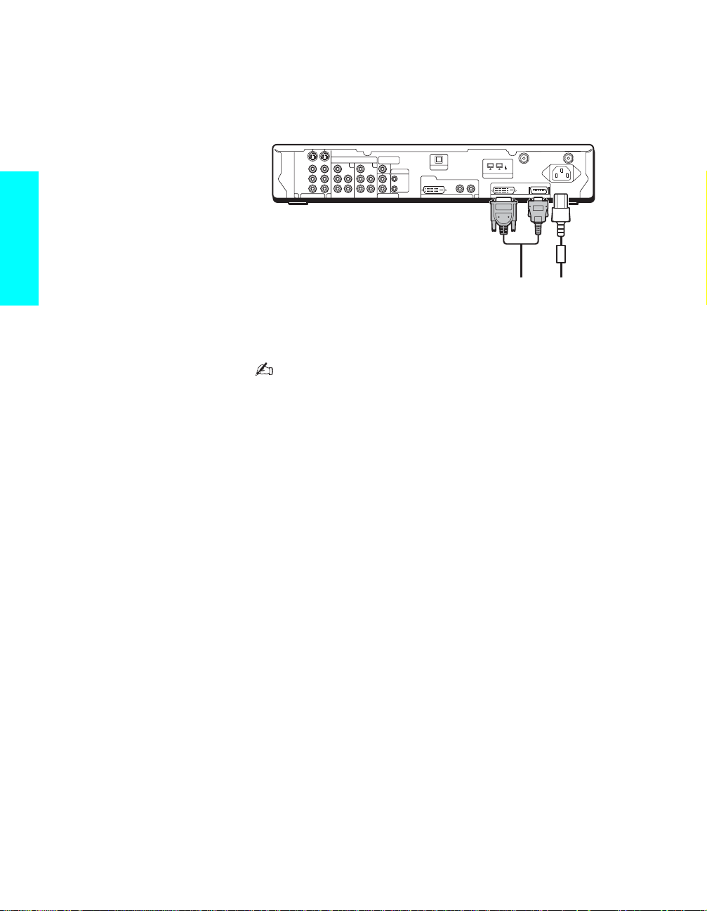
4 Connect the other end of display interface cable to the Media receiver unit’s
DISPLAY SIGNAL OUT jacks, and connect the AC power cord (supplied) to
the media receiver unit’s AC IN jack.
Setup
S VIDEO
1
VIDEO
AUDIO
L
R
VIDEO IN 3
Y
P
B
PRLR
HD/DVD IN
(1080i/720p/480p/480i)
Y
4
AUDIO
P
B
PR
SUB WOOFER
OUT
(VAR)
5
AUDIO
L
L
R
R
AUDIO OUT
(VAR/FIX)
CONTROL S
OPTICAL OUT
IN
DVI–HDTV
OUT
DVI–HDTV IN
R - AUDIO - L
(TV/DV/MICROMV)
6
i.LINK
WHITE BLACK
DISPLAY SIGNAL OUT
CABLE
VHF/UHF
S400
~
AC IN
Tighten the screw slowly until
the screw is stabilized.
Display interface
cable (supplied)
AC power cord
(supplied)
5 After making all connections, connect the AC power cords (supplied) to wall
outlets.
Be sure to use the supplied AC power cords.
When connecting optional compon ents, do not conne ct the A C
power cords to wall outle ts until you ha ve completed makin g all
connections.
Do not tighten the screw s too m u c h. It m ay damage the screws.
Handle the display interface cable with care. If you pull the
cable by catching your feet on the cable, this unit may fall and
cause injury.
Do not use damaged c ab le s, suc h as ca bles whose connector s
are deformed.
24
Page 27
Detaching the speakers (KDE61XBR950 only)
The speakers on the KDE61XBR950 can be detached.
Be sure to remove the speakers before installing the TV on a
wall, etc. Detaching the speakers from the TV should be
performed by qualified Sony personnel.
1 Place a protective s heet or cloth beneath the TV on a flat floor. Turn the
TV over so that you can see its rear panel.
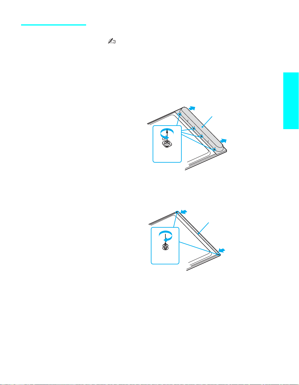
2 Remov e the fou r scr ews marked with arrows on the inside of the rear of
the speaker, then pull out the speaker straight to detach.
Rear of the display unit
Speaker
M4x10
screws
3 Attach the supplied frame bar and tighten with the supplied two screws.
Rear of the display unit
Setup
Screws
(supplied)
4 Repeat steps 2 and 3 for the other speaker.
Frame bar
(supplied)
25
Page 28

Basic Connections: Connecting a Cable or Antenna
The way in which you will connect your TV varies, depending on how your
home receives a signal (cable, cable box, antenna) and whether or not you
plan to connect a VCR.
If You Are Connecting See Page
Cable or Antenna Only
s No cable box or VCR
Cable Box and Cable Only
s Cable box unscrambles only some channels
(usually premium channels)
s No VCR
Setup
Cable Box Only
s Cable box unscrambl es all channels
s No VCR
If you are connecting a VCR
s See the connections described on pages 31 and 33.
26
27
28
Cable or Antenna
Only
For best results, use this con nection i f y ou ar e conn ecting a cabl e or a n
antenna and you:
s Do not need a cable box to unscramble channels. (If you have a cable
box, see page 28.)
s Do not intend to connect a VCR. (If you have a VCR, see pages 31 and
33.)
For antenna connection, use the supplied antenna cable.
Cable Type Connect As Shown
VHF Only or
combined
VHF/UHF
Cable
Note on Using This Connection
To Do This ... Do This ...
Switch the TV’s input between
the cable and antenna
Press ANT to switch back and forth between the TV’s VHF/UHF and CABLE
inputs.
Antenna
cable
(supplied)
75-ohm
coaxial
cable
When using an indoor antenna, such as rabbit-ear or dipoleantenna, keep the antenna away from the display unit. If not,
noise may appear on the screen.
VHF/UHF
CABLE
26
Page 29

Cable Box and Cable Only
For best results, use this connection if:
s Your cable company scrambles some channels, such as premium
channels (which requires you to use a cable b ox) , but does not scramble
all channels.
s You do not have a VCR. (If you have a VCR, see pages 31 and 33.)
With this connection you can:
s Use the TV remote control to change channels coming through the cable
box to the TV’s VHF/UHF input jack. (You must first program the
remote control for your specific cable box; see “Programming the
Remote Control” on page 52.)
s Use the TV remote control to change channels coming directly into the
TV’s CABLE input. (The TV’s tuner provides a better signal than the
cable box.)
Coaxial cable
Setup
CATV cable
Splitter
About Using This Connection with Dual Picture (Twin View, etc.) Features
Coaxial
cable
Coaxial cable
IN OUT
Cable box
VHF/UHF
Rear of Media receiver unit
CABLE
With this connection, you can use all the dual picture features for unscrambled
channels coming directly into the TV’s CABLE input jack.
Notes on Using This Connection
To Do This ... Do This ...
Use the cable box Tune the TV to the channel the cable box is set to (usually channel 3 or 4) and the n
use the cable box to switch channels.
Set up the TV remote control to
Program the remote control. See “Programming the Remote Control” on page 52.
operate the cable box
Activate the remot e cont rol to
Press FUNCTION repeatedly until the SAT/CABLE indicator lights up.
operate the cable box
Prevent the accidental switching
of TV channels
When using the ca ble box, you need the TV to stay on the channel the cable box is
set to (usually channe l 3 o r 4). You can use t he TV’s Channel Fix feature to lock in a
specific channel. For details, see “Using the Channel Menu” on page 10 3.
Switch
the TV’s input between
the cable box and cable
Press ANT to switch back and forth between the TV’s VHF/UHF (scrambled
channels) and CAB LE (unscrambled) inputs.
Do not leave the display indication of the cable box turned on.
(Continued)
27
Page 30

Cable Box Only For best results, use this connection if:
s Your cable compan y scrambles all channels, which requires you to use a
cable box.
s You do not have a VCR. (If you have a VCR, see pages 31 and 33.)
With this connection you can:
s Use the TV remote control to change channels coming through the cable
box to the TV’s VHF/UHF jack. (You must first program the remote
control for your specific cable box.)
Setup
About Using This Connection with Dual Picture (Twin View, etc.) Features
With this connection, all channels come into the TV through your cable box and
only one unscrambled signal is sent to the TV, so you cannot use the dual picture
features. If some of your channels are scrambled, but others are not, consider using
the “Cable Box and Cable” connecti on on page 27 instead.
To connect the cable box
1 Connect the CATV cable to the cable box’s input jack.
2 Use the supplied an tenna cable to con nect the cab le bo x’s output jack to
the TV’s VHF/UHF jack.
3 Run the Auto Setup program, as described in “Setting Up the Channel
List” on page 48.
CATV
cable
IN
Antenna cable
(supplied)
Rear of Media
receiver unit
VHF/UHF
OUT
Cable box
28
Page 31

Notes on Using This Connection
To Do This ... Do This ...
Use the cable box Tune the TV to the channel the cable box is set to (usually channel 3 or 4) and the n
use the cable box to switch channels.
Set up the TV remote control to
operate the cable box
Activate the remot e cont rol to
operate the cable box
Prevent the accidental switching
of TV channels
Program the remote control. See “Programming the Remote Control” on page 52.
Press FUNCTION repeatedly until the SAT/CABLE indicator lights up.
When using the ca ble box, you need the TV to stay on the channel the cable box is
set to (usually channe l 3 o r 4). You can use t he TV’s Channel Fix feature to lock in a
specific channel. For details, see “Using the Channel Menu” on page 10 3.
Do not leave the display indication of the cable box turned on.
Setup
29
Page 32

Connecting Optional Equipment
S
O
O
O
Use the directions in this section to connect the following optional
equipment:
If You Are Connecting See Page
VCR and Cable 31
VCR and Cable Box 33
Two VCRs for Tape Editing 35
Satellite Receiver 37
Satellite Receiver and VCR 39
DVD Player with Component Video Connectors 41
Setup
DVD Player with S VIDEO and Audio Connectors 43
Camcorder 44
Audio Receiver 45
Sub Woofer 46
Device with an Optical IN Connector 46
About Using
S VIDEO
If the optional equipment you are connecting has an S VIDEO jack
(shown at left), you can us e an S VIDEO cable for improved picture
quality (compared to an A/V cable). Because S VIDEO carries only
the video signal, you also need to connect audio cables for sound, as
shown below.
Example of an S VIDEO Connection
Equipment with S VIDEO
S VIDEO
cable
Audio cable
Rear of Media receiver unit
VIDE
VIDE
AUDI
30
Page 33

VCR and Cable For best results, use this connection if:
s Your cable company does not require you to use a cable box.
About Using This Connection with Dual Picture (Twin View, etc.) Features
With this connection, you can use all the dual picture features.
To connect the VCR and cable
1 Connect the CATV cable to the VCR’s VHF/UHF input jack.
2 Use the supplied antenna cable to connect the VCR’s VHF/UHF output
jack to the TV’s CABLE jack.
3 Use an A/V cable to connect the VCR’s A/V output jacks to the TV’s
A/V input jacks.
4 Run the Auto Setup program, as described in “Setting Up the Channel
List” on page 48.
Using S VIDEO jacks? See page 30.
Rear of Media receiver unit
Setup
S VIDEO
VIDEO
AUDIO
1
L
R
VIDEO IN 3
Y
P
B
PRLR
HD/DVD IN
(1080i/720p/480p/480i)
Y
4
AUDIO
P
B
PR
AUDIO
L
R
SUB WOOFER
(VAR)
OUT
5
R
AUDIO OUT
(VAR/FIX)
A/V cable
CONTROL S
L
IN
OUT
OPTICAL OUT
DVI–HDTV
DVI–HDTV IN
R - AUDIO - L
(TS/DV/MICROMV)
6
VHF/UHF
S400
i.LINK
WHITE BLACK
DISPLAY SIGNAL OUT
Antenna cable
(supplied)
CABLE
~
AC IN
CATV cable
31
Page 34

Notes on Using This Connection
To Do This ... Do This ...
Watch the VCR Press TV/VIDEO repeatedly to select the VCR input (VIDEO 1 in the illustration).
Watch cable channels Press TV/VIDEO repeatedly to select the cable input (CABLE in the illustration).
Set up the TV remote control to
operate the VCR
Activate the TV remo te control to
operate the VCR
Control VCR functions with the
TV remote control
Label video inputs to easily
Setup
identify equipment conn e ct ed to
the TV
If you have a non-Sony VCR, you mu st program the remote control. See
“Programming the Remote Control” on page 52.
Press FUNCTION repeatedly until the DVD/VCR indicator lights up.
See “Operating a VCR or D-VHS” on page 55.
See the instructions for setting up Video Labels on page 109.
Do not leave the display in dication of the VCR turned on.
32
Page 35

VCR and Cable Box For best results, use this connection if:
s Your cable company scrambles some channels, such as premium
channels (which requires you to use a cable b ox) , but does not scramble
all channels.
About Using This Connection with Dual Picture (Twin View, etc.) Features
With this connection, you can use all the dual picture features.
With this connection you can:
s Use the TV remote control to change channels coming through the cable
box. (You must first program the remote control for your specific cable
box; see “Programming the Remote Control” on page 52.)
s Use the TV remote control to change channels coming directly into the
TV’s CABLE jack. (The TV’s tuner provides a better signal than the
cable box.)
s Record channels coming through the cable box and channels coming
directly into the TV.
To connect a VCR and cable box, you need:
s A splitter, which is a small, inexpen sive device that you can purchase at
your local electronics store.
s Three coaxial cables.
s One A/V cable or one S VIDEO cable with audio cables.
To connect the VCR and cable box
1 Connect the CATV cable to the single (input) jack of the splitter.
2 Use the supplied antenna cable to connect one of the splitter’s two
output jacks to the TV’s CABLE jack.
3 Use a coaxial cable to connect the splitter’s other output jack to the
cable box’s input jack.
4 Use a coaxial cable to connect the cable box’s output jack to the VCR’s
RF input jack.
5 Use an A/V cable to connect the VCR’s A/V output jacks to the TV’s
A/V input jacks.
6 Use a coaxial cable to connect the VCR’s RF output jack to the TV’s
VHF/UHF jack.
7 Run the Auto Setup program, as described in “Setting Up the Channel
List” on page 48.
Using S VIDEO jacks? See page 30.
Setup
33
Page 36

Rear of Media receiver unit
S VIDEO
VIDEO
AUDIO
1
L
R
VIDEO IN 3
Y
B
P
PRLR
HD/DVD IN
(1080i/720p/480p/480i)
Y
4
AUDIO
B
P
PR
AUDIO
L
R
SUB WOOFER
OUT
5
AUDIO OUT
(VAR/FIX)
(VAR)
L
R
CONTROL S
IN
OUT
OPTICAL OUT
DVI–HDTV
DVI–HDTV IN
R - AUDIO - L
(TS/DV/MICROMV)
6
VHF/UHF
S400
i.LINK
WHITE BLACK
DISPLAY SIGNAL OUT
CABLE
~ AC IN
CATV
cable
Antenna cable
Setup
VCR
(supplied)
Coaxial cable
(not supplied)
Cable box
A/V cable
Splitter
(not supplied)
Coaxial cable
(not supplied)
CATV cable
Notes on Using This Connection
To Do This ... Do This ...
Watch cable (unscrambled)
Press TV/VIDEO repeatedly to select the cable input (CABLE in the illustration).
channels
Watch cable box (scrambled)
channels
Turn on the VCR and tune it to the channel the cable box is set to (usually channel 3
or 4). Press TV/VIDEO repeatedly to select the VCR input (VIDEO 1 in the
illustration). Use the cable box to change channels.
Watch the VCR Press TV/VIDEO repeatedly to select the VCR input (VIDEO 1 in the illustration).
Set up the TV remote control to
operate the cable box or VCR
Activate the remot e cont rol to
operate the cable box or VCR
If you have a non-Sony VCR, you mu st program the remote control. See
“Programming the Remote Control” on page 52.
For the cable box, press FUNCTION repeatedly until the SAT/CABLE indicator
lights up. For the VCR, press FUNCTION repeatedly until the DVD/VCR indicator
lights up.
Control specific cable box and
VCR functions with the TV
See “Operating a Cable Box” on page 56 and “Operating a VCR or D-VHS” on page
55.
remote control
Label video inputs to easily
See the instructions for setting up Video Labels on page 109.
identify equipment conn e ct ed to
the TV
34
Do not leave the display in dication of the cable box and VCR
turned on.
Page 37

Two VCRs for Tape
F
O
R
Editing
Connecting two VCRs lets you record from one VCR to the other. By
connecting them as shown below, you can view (monitor) what is being
recorded.
To connect two VCRs for tape editing
1 Use an A/V cable to connect the playback VCR’s A/V output jacks to
the recording VCR’s A/V input jacks.
2 Use an A/V cable to connect the recording VCR’s A/V output jacks to
the TV’s AUDIO and VIDEO IN jacks.
Using S VIDEO jacks? See page 30.
Setup
Playback VCR
A/V cable
Recording VCR
Rear of Media receiver unit
S VIDEO
VIDEO
AUDIO
1
L
R
VIDEO IN 3
Y
P
B
PRLR
HD/DVD IN
(1080i/720p/480p/480i)
Y
4
AUDIO
P
B
PR
AUDIO
L
R
5
SUB WO
OUT
(VA
AUDIO
(VAR/
A/V cable
When connecting two VCRs for tape editing;
– you cannot edit a tape with copy protection.
– do not connect the TV’s A/V input jack and output jack to your
VCRs at the same time to avoid looping the signal.
L
R
35
Page 38

Notes on Using This Connection
To Do This ... Do This ...
Set up the TV remote control to
operate the VCR(s)
Activate the TV remo te control to
operate the VCR(s)
Control VCR functions with the
TV remote control
Label video inputs to easily
identify equipment conn e ct ed to
the TV
Setup
If you have a non-Sony VCR, you mu st program the remote control. See
“Programming the Remote Control” on page 52.
Press FUNCTION repeatedly until the DVD/VCR indicator lights up.
See “Operating a VCR or D-VHS” on page 55.
See the instructions for setting up Video Labels on page 109.
36
Page 39

Satellite Receiver To connect a satellite receiver
1 Connect the satellite antenna cable to the satellite receiver’s satellite
input jack.
2 Use an A/V cable to connect the satellite receiver’s A/V output jacks to
the TV’s A/V input jacks.
3 Connect the supplied antenna cable from your cable or antenna to the
TV’s CABLE or VHF/UHF jack.
4 Run the Auto Setup program, as described in “Setting Up the Channel
List” on page 48.
Using S VIDEO jacks? See page 30.
Rear of Media receiver unit
Setup
S VIDEO
VIDEO
AUDIO
1
L
R
VIDEO IN 3
Y
P
B
PRLR
HD/DVD IN
(1080i/720p/480p/480i)
Y
4
AUDIO
AUDIO
P
L
B
R
PR
Satellite receiver
A/V cable
SUB WOOFER
OUT
(VAR)
5
AUDIO OUT
(VAR/FIX)
CONTROL S
L
R
IN
OUT
OPTICAL OUT
DVI–HDTV
DVI–HDTV IN
R - AUDIO - L
Satellite
antenna
cable
(TS/DV/MICROMV)
6
VHF/UHF
S400
i.LINK
WHITE BLACK
DISPLAY SIGNAL OUT
Antenna cable
(supplied)
CABLE
~
AC IN
CATV cable
(not supplied)
37
Page 40

Notes on Using This Connection
To Do This ... Do This ...
Watch the satellite receiver Press TV/VIDEO repeatedly to select the satellite receiver input
(VIDEO 1 in the illustration).
Set up the TV remote control to operate the
satellite receiver
Activate the TV remote control to operate the
satellite receiver
Control satellite receiver functions with the TV
remote control
Label video inputs to easily identify equipment
connected to the TV
Setup
If you have a non-Sony satellite receiver, you must program the
remote control. See “Programming the Remote Control” on page 52.
Press FUNCTION repeatedly until the SAT/CABLE indicator lights
up.
See “Operating a Satellite Receiver” on page 55.
See the instructions for setting up Video Labels on page 109.
Do not leave the Electric Pr ogram Guide and displa y ind ication
turned on.
38
Page 41

Satellite Receiver and VCR
Rear of Media receiver unit
To connect a satellite receiver and VCR
1 Connect the satellite antenna cable to the satellite receiver’s satellite
input jack.
2 Connect the CATV cable to the VCR’s VHF/UHF input jack.
3 Use the supplied antenna cable to connect the VCR’s VHF/UHF output
jack to the TV’s CABLE jack.
4 Use an A/V cable to connect the satellite receiver’s A/V output jacks to
the VCR’s A/V input jacks.
5 Use an A/V cable to connect the VCR’s A/V output jacks to the TV’s
A/V input jacks.
6 Run the Auto Setup program, as described in “Setting Up the Channel
List” on page 48.
Using S VIDEO jacks? See page 30.
Setup
S VIDEO
VIDEO
AUDIO
1
L
R
VIDEO IN 3
Y
P
B
PRLR
HD/DVD IN
(1080i/720p/480p/480i)
Y
4
AUDIO
P
B
PR
AUDIO
L
R
5
SUB WOOFER
(VAR)
OUT
CONTROL S
L
R
AUDIO OUT
(VAR/FIX)
Antenna
cable
(supplied)
IN
OUT
OPTICAL OUT
DVI–HDTV
DVI–HDTV IN
Satellite receiver
A/V cable
CATV cable
R - AUDIO - L
(TS/DV/MICROMV)
6
i.LINK
VHF/UHF
S400
WHITE BLACK
DISPLAY SIGNAL OUT
Satellite
antenna
cable
VCR
CABLE
~ AC IN
A/V cable
39
Page 42

Notes on Using This Connection
To Do This ... Do This ...
Watch the satellite receiver Press TV/VIDEO repeatedly to select the VCR input (VIDEO 1 in the illustration).
The VCR may need to be turned on and set to the satellite receiver input.
Watch the VCR Press TV/VIDEO repeatedly to select the input to which the VCR is connected
(VIDEO 1 in the illustration).
Set up the TV remote control to
operate the satellite receiver or
VCR
Activate the TV remo te control to
operate the satellite receiver or
VCR
Setup
Control satellite receiver and
VCR functions with the TV
remote control
Label video inputs to easily
identify equipment conn e ct ed to
the TV
If you have a non-Sony VCR or satellite receiver, you must program the remote
control. See “Programming the Remote Control” on page 52.
For the satellite receiver, press FUNCTION repeatedly until the SAT/CABLE
indicator lights up. For the VCR, press FUNCTION repeate d ly un til the DVD/VCR
indicator lights up.
See “Operating a Satellite Receiver” on page 55 and “Operating a VCR or D-VHS ”
on page 55.
See the instructions for setting up Video Labels on page 109.
Do not leave the Electric Pr ogram Guide and displa y ind ication
turned on.
40
Page 43

DVD Player with
S
O
O
O
N
3
SU
R
OUT
(VAR)
N
(
)
OUT
Component
Video Connectors
VIDE
VIDE
AUDI
VIDEO I
Y
P
For best results, use this connection if your DVD player has component
video (Y, P
To connect a DVD player with component video connectors
1 Use three separate co mponent video cables to connect the D VD player’s
Y, P
2
Use an audio cable to connect the DVD player’s audio output jacks to the
TV’s VIDEO 4 or 5 audio input jacks.
Rear of Media receiver unit
AUDIO
L
B WOOFE
5
1080i/720p/480p/480i
B
L
HD/DVD I
4
AUDIO
Y
P
B
B, PR) jacks.
B and PR jacks to the Y, PB and PR jacks (VIDEO 4 or 5) on the TV.
The Y, PB and PR jacks on your DVD player are sometimes
labeled Y, C
B and CR, or Y, B-Y and R-Y. If so, connect the
cables to their matching color jacks.
Component video cable
DVD player
CONTROL S
IN
L
Setup
Audio cable
41
Page 44

Notes on Using This Connection
To Do This ... Do This ...
Wa tch the DVD player Press TV/VIDEO repeatedly to select the D VD inp ut (VIDEO 4 in the illustration ).
Set up the TV remote control to
operate the DVD player
Activate the TV remo te control to
operate the DVD player
Control DVD function s with the
TV remote control
Label video inputs to easily
identify equipment conn e ct ed to
the TV
Setup
If you have a non-Sony DVD player, you must program the remote control. See
“Programming the Remote Control” on page 52.
Press FUNCTION repeatedly until the DVD/VCR indicator lights up.
See “Operating a DVD Player” on page 56.
See the instructions for setting up Video Labels on page 109.
You cannot record the signal from any equipment connected
into the Y, P
Do not leave a still ima ge, suc h as the DVD men u, disp layed on
the screen.
B, PR jacks.
42
Page 45

DVD Player with
S
O
O
O
S VIDEO and Audio
Use this connection if your DVD player does not have component video (Y,
P
B, PR) jacks.
Connectors
To connect a DVD player with A/V connectors
1 Use an audio cable to connect the DVD player’s audio output jacks to
the TV’s audio input jacks.
2 Use an S VIDEO cable to connect the DVD player’s S VIDEO jack to
the TV’s S VIDEO jack.
Rear of Media receiver unit
S VIDEO
DVD player
cable
Audio cable
Notes on Using This Connection
To Do This ... Do This ...
Wa tch the DVD player Press TV/VIDEO repeatedly to select the D VD inp ut (VIDEO 1 in the illustration ).
Set up the TV remote control to
operate the DVD player
Activate the TV remo te control to
If you have a non-Sony DVD player, you must program the remote control. See
“Programming the Remote Control” on page 52.
Press FUNCTION repeatedly until the DVD/VCR indicator lights up.
operate the DVD player
Control DVD function s with the
See “Operating a DVD Player” on page 56.
TV remote control
Label video inputs to easily
See the instructions for setting up Video Labels on page 109.
identify equipment conn e ct ed to
the TV
VIDE
VIDE
AUDI
Setup
Do not leave a still ima ge, suc h as the DVD men u, disp layed on
the screen.
43
Page 46

Camcorder For easy connection of a camcorder , the TV has front A/V input jacks. If you
prefer, however, you can connect the camcorder to the TV’s rear A/V input
jacks.
To connect a camcorder
Use an A/V cable to connect the camcorder’s A/V output jacks to the TV’s
A/V input jacks.
Using S VIDEO jacks? See page 30.
Setup
Front of the Media receiver unit
VIDEO
Notes on Using This Connection
To Do This ... Do This ...
Watch the camcorder Press TV/VIDEO repeatedly to sele ct the camcorder input (VIDEO 2 in the
illustration).
Label video inputs to easily
See the instructions for setting up Video Labels on page 109.
identify equipment conn e ct ed to
the TV
–AUDIO–
VIDEO L R
VIDEO 2 INPUT
Camcorder
A/V cable
To A/V output
44
Do not leave a still image of the camcorder or digital camera
displayed on th e screen.
Page 47

Audio Receiver For improved sound quality, you may want to play the TV’s audio through
AUDIO OUT
(VAR/FIX)
CO
S
SU
R
OUT
(VAR)
D IN
)
OUT
your stereo system.
To connect an audio system
1 Use an audio cable to connect the TV’s audio output jacks to the audio
receiver’s line input jacks.
Rear of Media receiver unit
80p/480i
B WOOFE
NTROL
Receiver
To line input
Audio cable
2 Using the TV’s Audio Menu, set the Speaker option to Off. Then set
the Audio Out option to Fixed or Variable, depending on how you want
to control the volume. For details, see “Using the Audio Menu” on page
99.
3 Turn on the audio receiver, and then set the receiver’s line input to the
jack into which you connected the TV.
Setup
45
Page 48

Sub Woofer Use a monaural audio cable to connect the TV’s SUB WOOFER OUT jack
R
L
6
OUT
(
)
CO
S
(VAR)
OUT
O
OUT
HDTV
L
6
OUT
(
)
CO
S
SU
R
OUT
(VAR)
OUT
OPTICAL OUT
to the sub woofer’s input jack.
Monaural audio cable (not supplied)
Sub woofer
input
Setup
Device with an Optical IN Connector
NTROL
AUDIO
VAR/FIX
Rear of Media receiver unit
PTICAL
R - AUDIO -
Sub woofer
You can use the TV’s DIGITAL AUDIO (OPTICAL) OUT jack to connect a
digital audio device that is PCM/Dolby Digital compatible, such as an audio
amplifier.
s Using an optical cable, connect the device’s OPTICAL IN jack to the
TV’s DIGITAL AUDIO (OPTICAL) OUT jack.
Rear of Media receiver unit
B WOOFE
NTROL
R - AUDIO -
AUDIO
VAR/FIX
46
Audio amplifier
LINE
OUT
L AUDIO R
LINE
IN
OPTICAL
IN
Optical cable
Page 49

Using the CONTROL
O
OUT
(
)
CO
S
OUT
(VAR)
)
OUT
O
OUT
S Feature
CONTROL S allows you to control your system and other Sony equipment
with one remote control. In addition to allowing you to control multiple
devices with one remote control, the CONTROL S feature allows you to
always point your remote control at your TV, instead of having to point it at
the other equipment, which might be hidden or out of direct line of sight.
Use CONTROL S IN to send signals to the TV.
Use CONTROL S OUT to send signals to connected equipment.
Setup
CONTROL S
IN
OUT
i
NTROL
AUDIO
VAR/FIX
Rear of Media receiver unit
PTICAL
R - AUDI
47
Page 50

Setting Up the Channel List
After you finish connecting your TV, you need to run Auto Setup, which
automatically set up available analog and digital channels. The Auto
Program screen appears when you turn on your TV for the first time after
hooking it up. If you do not want to set up the channels at this time, you can
do it later by selecting the Auto Program option in the Channel Menu (see
page 103).
The Auto Setup feature doe s not apply f or installations that use
a cable box for all channel selection.
Setup
Using Auto Setup To run Auto Setup the first time you turn on your TV
1 Press POWER to turn on the TV.
The Initial Setup screen appears.
2 Press V or v to select the on-screen display language. Then press
ENTER.
The message “Start auto program now?” appears.
3 Press V or v to select “Yes”, then press ENTER.
Auto Setup automatically creates a list of receivable channels. When
finished, the lowest numbered channel is displayed.
To run Auto Setup again at a later time
s Use the Auto Program feature as described on page 103.
48
To add individual digital channels
s Use the Digital Channel feature as described on page 70.
Auto Program may take up to 30 minutes to complete. A progress
bar is displayed while the channel list is being created.
Page 51

Using the Remote Control
Overview
This chapter describes how to set up, program, and use the TV’s remote
control.
Topic Page
Inserting Batteries 49
Button Descriptions 50
Programming the Rem ote Control 52
Using Other Equipment with Your TV Remote Control 55
Inserting Batteries
1 Open the battery compartment as illustrated below.
2 Insert two size AA batteries (supplied) by matching the e and E
terminals on the batteries to the diagram inside the battery compartment.
3 Close the battery compartment.
m
<
Remove the batteries to avoid damage from possible battery
leakage whenever you anticipate that the remote control will
not be used for an extended period.
Handle the remote control with care.
Avoid dropping it, getting it wet, placing it in direct sunlight,
near a heater , or where the h umi dity is high.
49
Page 52

Button Descriptions
Remote Control
RM-Y1000
Button Description
1 MUTING Press to mute the sound. Press again or press VOL+ to restore
the sound.
2 FUNCTION
button and
indicators
3 PIC OFF Press to have the TV screen turn off. For details, see page 65.
4 SLEEP Press repeatedly until the TV displays the time in minutes (15,
5 GUIDE Press to display the digital program guide.
If FUNCTION is switched on SAT/CABLE
GUIDE* Press to display the progr am guid e of yo ur s atellite program
6 Use with 0-9 and ENTER buttons to select digital channels
7 PICTURE Press repeatedly to cycle through the available video picture
8 WIDE Press repeatedly to step through the Wid e Mo de setting s:
9 Press V v B b to move the on-screen cursor. To select an ite m,
If FUNCTION is switched on SAT/CABLE, DVD/VCR or i.LINK
Transport
Buttons
q; (Twin View) Press to turn on and off Twin View. For deta ils, see page 60.
qa ANT Press to switch between the sources connected to the TV’s
If FUNCTION is switched on SAT/CABLE
INDEX* Press to display the index of your satellite program provider.
qs VOL +/– Press to adjust the volume.
qd EXIT Press to exit the on-screen menu or display and return to
Press to have the remote control operate the equipment you
want. Press repeatedly until the indicator of the desired
equipment lights up.
For details, see “Programming the Remote Control” on page
52.
30, 45, 60 or 90) that you want the TV to remain on before
shutting off. To cancel Sleep Timer, press SLEEP repeatedly
until SLEEP OFF appears.
provider.
(for example, 2.1). For details on selecting digital channels,
see page 68.
modes: V ivi d, Stand ard , Pro. Also available in the Video
Menu. For details, see “Selecting Video Options” on page 96.
Wide Zoom, Normal, Full, Zoom. Also available in the
Screen menu. For details, see pages 59 and 101.
press .
m Rewind
H Play
x Stop
M Fast forward
X Pause
VHF/UHF and CABLE inputs.
normal viewin g.
50
Page 53

Button Description
qf Power
Buttons
qg RESET Press to reset the settings to the factory defaults. See pages 96
If FUNCTION is switched on DVD/VCR
z REC Press to record a program.
qh TV/VIDEO Press repeatedly to cycle through the video equi pment
qj DISPLAY Press once to display the current channel number, current time,
qk JUMP Press to jump back and forth between two channels. The TV
ql 0 - 9
ENTER
w; FAVORITES Press to display the Favorite Channel s list. Fo r detail s, see
wa FREEZE Press to freeze the picture. Press again to restore the picture.
ws i.LINK Press to display the i.LINK Control Panel. For information on
wd
MEMORY
STICK
wf MENU Press to display the Menu. Press again to exit from the Menu.
wg CH +/– Press to scan through channels. To scan quickly through
* If not Sony brand, requires that you first program the remote control (page
52).
SAT/CABLE*: Press to turn on and off the satellite receiver,
cable box, and other audio/video equipment you have
programmed into the remote control. For instructions, see
“Programming the Remote Control” on page 52.
POWER: Press to turn on a n d off the TV.
and 99. Also used to clear Favorite Channels (see page 63).
connected to the TV’s video inputs.
and channel label. If set, the current channel number will
display for 10 seconds.
alternates between the current channel and the last channel
that was selected.
Press 0 - 9 to select a channel; the channel changes after 3
seconds. Press ENTER to change channels immediately.
page 63.
For details, see “Using the Freeze Function” on page 64.
using the i.LINK Control Panel, see page 91.
Press to display the Memory Stick Menu. For details, see
“Using the Memory Stick Viewer” on page 71.
For details, see page 95.
channels, press and hold down either CH.
Remote Control
51
Page 54

Programming the Remote Control
The remote control is preset to operate Sony brand video equipment.
Sony Equipment Programmable Co de Numb e r
Beta, ED Beta VCRs 303
8 mm VCR 302
VHS VCR 301
DVD player 751
i.LINK 901
If you have video equipment other than Sony brand that you want to control
with the TV’s remote control, use the following procedure to program the
remote control.
The equipment must have infrared (IR) remote capability in
order to be used with the remote control.
1 Turn to the list of “Manufacturer’s Codes” on page 53, and find the
three-digit code number for the manufacturer of your equipment. (If
more than one code number is listed, use the number listed first.)
2 Press FUNCTION repeatedly until the DVD/VCR, SAT/CABLE or
i.LINK indicator lights up.
Remote Control
3 Press SAT/CABLE for five seconds until the indicator of the selected
input flashes.
4 While the desired indicator is flashing, enter the three-digit
manufacturer’s code number.
5 Press ENTER.
You must do step 5 within 10 seconds of step 4, or you must
redo steps 4 through 5.
6 To check if the code number works, aim the TV’s remote control at the
equipment and press POWER that corresponds with that equipment. If
it responds, you are done. If not, try using another code listed for that
manufacturer.
52
Notes
s If more than one code number is lis ted, try entering them one by one
until you come to the correct code for your equipment.
s If you enter a new code number, the code number you previously
entered at that setting is erased.
s In some cases, you may not be able to operate your equipment with the
supplied remote contr ol. In such cases, use the equipment’ s own remote
control unit.
s Whenever you remove the batteries to replace them, the code numbers
may revert to the factory setting and must be reset.
Page 55

Manufacturer’s Codes
VCRs
Manufacturer Code
Sony 301, 302, 303
Admiral
327
(M. W a rd)
Aiwa 338, 344
Audio Dynamic 314, 337
Broksonic 319, 317
Canon 309, 308
Citizen 332
Craig 302, 332
Criterion 315
Curtis Mathes 304, 338, 309
Daewoo 341, 312, 309
DBX 314, 336, 337
Dimensia 304
Emerson 319, 320, 316,
317, 318, 341
Fisher 330, 335
Funai 338
General Electric 329, 304, 309
Go Video 322, 339, 340
Goldstar 332
Hitachi 306, 30 4, 305,
338
Instant Replay 309, 308
JC Penney 309, 305, 304,
330, 314, 336,
337
JVC 314, 336, 337,
345, 346, 347
Kenwood 314, 336, 332,
337
LG 332
LXI (Sears) 332, 305, 330,
335, 338
Magnavox 308, 309, 310
Marantz 314, 336, 337
Marta 332
Memorex 309, 335
Minolta 305, 304
Mitsubishi/
MGA
323, 324, 325,
326
Multitech 325, 338, 321
NEC 314, 336, 337
Manufacturer Code
Olympic 309, 308
Optimus 327
Orion 317
Panasonic 308, 309, 306,
307
Pentax 305, 304
Philco 308, 309
Philips 308, 309, 310
Pioneer 308
Quasar 308, 309, 306
RCA/
PROSCAN
304, 305, 308,
309, 311, 312,
313, 310, 329
Realistic 309, 330, 328,
335, 324, 338
Sansui 314
Samsung 322, 313, 321
Sanyo 330, 335
Scott 312, 313, 321,
335, 323, 324,
325, 326
Sharp 327, 328
Signature 2000
338, 327
(M. W a rd)
SV2000 338
Sylvania 308, 3 09, 338,
310
Symphonic 338
Tashiro 332
Tatung 314, 336, 337
Teac 314, 336, 338,
337
Technics 309, 308
Tosh iba 312, 311
Wards 327, 3 28, 335,
331, 332
Ya maha 314, 330, 336,
337
Zenith 331
Laserdisc Players
Manufacturer Code
Sony 701
Panasonic 704, 710
Pioneer 702
DVD Players
Manufacturer Code
Sony 751
Sony (i.LINK) 901
APEX 762
General Electric 755
Hitachi 758
JVC 756
Magnavox 757
Mitsubishi 761
Oritron 759
Panasonic 753
Philips 757
Pioneer 752
RCA/Proscan 755
Samsung 758
Toshiba 754
Zenith 760
AV Rece ive r
Manufacturer Code
*1
Sony 651
5.1 DVD AV System (DA V)
Manufacturer Code
*2
Sony 601
Cable Boxes
Manufacturer Code
Sony 230
Hamlin/Regal 222, 223, 224,
225, 226
Jerrold/G. I. 201, 202, 203,
204, 205, 206,
207, 208, 218
Oak 227, 228, 229
Panasonic 219, 220, 221
Pioneer 214, 215
Scientific Atl a nta 209, 210, 211
Tocom 216, 217
Zenith 212, 213
Remote Control
53
Page 56

Satellite Receivers
Manufacturer Code
Sony 801
Dish Network 810
Echostar 810
General Electric 802
Hitachi 805
Hughes 804
Mitsubishi 809
Panasonic 803
RCA/
PROSCAN
Toshiba 806, 807
*1
This manufacturer code might
not work for some models. The
following FY03 STR & AVD
models are capable of
functioning with this code.
STR-DA9000ES/
STR-DA5000ES/
STR-DA3000ES/
STR-DA2000ES/
Remote Control
STR-DA1000ES/
STR-DE995/STR-DE895/
STR-DE695/STR-DE595/
HT-C800DP/AVD-S500ES/
AVD-S700ES
*2
This manufacturer code might
not work for some models. The
following FY03 DAV models are
capable of functioning with this
code.
DA V -FC7/DAV -FC8/DA V -FC9
802, 808
54
Page 57

Using Other Equipment with Your TV Remote Control
All Equipment
To Do This ... Do This ...
Operating a VCR or D-VHS
Switch the TV’s input to the VCR,
DVD player, or other connected
equipment
Set up the TV remote control to
operate non-Sony equi pment
To Do This ... Press
Activate the remote control to
operate the VCR
Turn on/off SAT/CABLE
Change channels
Record z REC
Play
Stop x
Fast forward M
Rewind the tape m
Pause X
Search the picture forward or
backward
Press TV/VIDEO repeatedly to cycle through
the video equipme nt co nn e cted to the TV’s
video inputs.
You must program the remote control the first
time you use it. See “Prog ramming the Remo te
Control” on page 52.
FUNCTION repeatedly until the DVD/VCR or
i.LINK in dicator lights up.
CH +/–
M or m during playback
(release to resume normal playback)
Remote Control
Operating a Satellite Receiver
To Do This ... Press
Activate the remote control to
operate the satellite receiver
Turn on/off SAT/CABLE
Select a channel 0-9, ENTER
Change channels CH +/–
Back to previous channel JUMP
Display channel number DISPLAY
Display SAT Guide GUIDE
Display SAT Index INDEX
Display SAT Menu MENU
Move highlight (cursor) V v B b
Select item
FUNCTION repeatedly until the SAT/CABLE
indicator lights up.
55
Page 58

Operating a Cable Box
Operating a DVD Player
Remote Control
To Do This ... Press
Activate the remote control to
operate the cable box
Turn on/off SAT/CABLE
Select a channel 0-9, ENTER
Change channels CH +/–
Back to previous channel JUMP
To Do This ... Press
Activate the remote control to
operate the DVD
Turn on/off SAT/CABLE
Play
Stop x
Pause X
Step through different
tracks of the disc
Step through different chapters
of a video disc
FUNCTION repeatedly until the SAT/CABLE
indicator lights up.
FUNCTION repeatedly until the DVD/VCR
indicator lights up.
M to step forward or m to step backward
CH+ to step forward or CH– to step backward
Operating an MDP (Laserdisc Player)
56
To Do This ... Press
Activate the remote control to
operate the MDP
Turn on/off SAT/CABLE
Play
Stop x
Pause X
Search the picture forward or
backward
Search a chapter forward or
backward
FUNCTION repeatedly until the indicator of the
position you programmed for the MDP play er
lights up.
M or m during playback
(release to resume normal playback)
CH +/–
Page 59

Using the Features
Overview
This chapter describes how to use the features of your TV.
Topic Page
Watching TV 58
Using Wid e Mo de 59
Using Twin View 60
Using Favorite Channels 63
Using the Freeze Function 64
Using Picture Off 65
57
Page 60

Watching TV
z
t
For a complete list of all
he functions of the remote
control, see page 50.
Features
To Do This ... Do This ...
Activate the remote control to
operate the TV
Turn on/off the TV Press POWER
Tune directly to a channel To tun e to analog channels, press 0-9 and then
Adjust the volume Press VOL +/–
Mute the volume Press MUTING (press again to unmute)
Alternate back and forth between
two channels
Display the current channel
number (and other information)
Switch the TV’s input to the VCR,
DVD player, or other connected
equipment
Change video and audio options,
customize the TV’ s setup, set
parental controls, and more
Switch the TV’s input between
sources connected to the TV’s
VHF/UHF and CABLE inputs
Switch the TV’s input to a
connected i.LINK device
Press FUNCTION repeatedly until the TV
indicator lights up.
ENTER (or wait 3 seconds).
For digital subchannels, press 0-9, , press
0-9 again, and then ENTER.
For example, to select subchannel 2.1, press 2,
, 1, and then press ENTER.
You can also select digital channels
using the digital program guide.
See page 67 for details.
Press JUMP
The TV alternates between the current channel
and the last channel tuned.
Press DISPLAY once to display the channel
number, current time, wide mode, and channe l
label (if set). Press DISPLAY again to turn
Display off.
Press TV/VIDEO repeatedly to cycle through
the video equipment connected to the TV’s
video inputs.
Press MENU to display the Menu. For details,
see “Using the Menus” on page 95.
Press ANT to alternate between sources
connected to the TV’s VHF/UHF and CABLE
inputs.
Press i.LINK to display a list of a available
i.LINK devices, and select the desired device
from the list. See page 90 for details.
58
Page 61

z
z
Using Wide Mode
Wide Zoom is
recommended f or 4:3 picture
to prevent image retention.
z You can also access the
Wide Mode settings in the
Screen menu. For details,
see page 101.
When you cha nge channels
or inputs, the Wide Mode
settings revert to the 4:3
Default setting in the Screen
menu. To retain the current
Wide Mode setting as
channels and inputs are
changed, set 4:3 Default to
Off. For details, see page 102.
Wide Screen mode lets you watch 4:3 normal broadcasts in several Wide
Screen modes (16:9 aspect ratio).
When viewing high-definition programs broadcast in
720p/1080i, it is not possible to change between Wide Screen
modes.
s Press WIDE repeatedly to toggle through the following Wide Mode
settings.
Wide Zoom enlar ges the 4:3 picture,
while the upper and lower p arts of the
picture are condensed to fit the 16:9
screen. The picture has a normal
appearance, as much as possible.
Normal returns the 4:3 picture to its
original size. Black bars are visible at
left and right sides to fill the 16:9
screen.
Full Mode stretches the 4:3 picture
horizontally only, to fill the 16:9
screen. The picture has an elongated
appearance.
Features
Zoom Mode enlarg es the 4:3 pictur e
horizontally and vertically to an
equal aspect ratio that fills the 16:9
screen. Useful for watching
Letterbox movies.
59
Page 62

Using Twin View
Twin View lets you see two pictures from two sources — from an antenna,
VCR, DVD, etc. — on the screen at the s ame time. You hear the sound from
only one of the sources at a time, but you can choose which source’s sound is
selected. You can also change the relative size of each of the pictures.
Using Twin View for an extended period of time may result in
image retention.
Displaying Twin Pictures
1 Tune the TV to a working channel.
2 Press .
A second picture appears.
,
<
To cancel Twin View and watch the active picture
s Press or .
Factors Affect ing Twin View
s If you use a cable box, you can view the cable box output in one window and view a different source
Features
(such as a VCR or DVD player) in the second window by using TV/VIDEO. For details, see
“Connecting Optional Equipment” on page 30.
s Digital TV channels, as well as any sources connected to the VIDEO 4, VIDEO 5, and VIDEO 6
inputs, display in the left window, bu t not the right.
s If you are viewing a 4:3 source and a 16:9 enhanced source (such as a DVD) side by side, the 4:3
source appears larger.
s Twin View does not display channels that are blocked by parental settings (see page 105).
60
Page 63

Activating the Picture
To activate the picture in the
right window
s Press b.
T o activ ate the picture in the left
window
s Press B.
,
<
Functions Available in the Active Window
To Do This ... Do This ...
Tune to a channel Press 0-9 and then ENTER (or wait 3 seconds)
or
Press CH+/–
Adjust the volume Press VOL +/–
Mute the volume Press MUTING (press again to unmute)
Switch the TV’s input between
sources connected to the TV’s
VHF/UHF and CABLE inputs
the TV’s input between
Switch
sources connected to the TV’s
A/V inputs
Change the picture size Press V or v. (For details, see “Changing the
Press ANT
Press TV/VIDEO
Picture Size” on page 62.)
Features
61
Page 64

Changing the Picture Size
The zoom feature lets you vary the relative size of the left and right pictures.
1 Press B or b to activate the picture
that you want to resize.
2 Press V to enlarge the picture.
3 Press v to make the picture
smaller.
Features
62
When you adjust the picture sizes, the TV memorizes the change. The next
time you use the Twin View function, the memorized sizes appear.
Page 65

Using Favorite Channels
The Favorite Channels feature lets you select programs from a list of up to
16 favorite channels that you specify.
Creating a List of Favorite Channels
z For details on using the
Channel Menu, see page
103.
Displaying a List of Favorite Channels
z To assign Channel
Labels (e.g., ABC, HBO,
MTV, etc.) to channel
numbers, as s hown at right,
use the Channel Label
feature in the Channel
Menu (see page 104).
1 Press MENU to display the Menu.
2 Press B or b to highlight the Channel icon and press .
3 Press to select Favorite Channels.
4 Press to select Program.
5 Press V or v to highlight a Favorite Channel number (1-16) and press
.
6 Press V or v to highlight a channel you want to assign to the Favorite
Channel number. A preview of the highlighted channel appears in the
upper right of the screen. Press to select that channel as a Favorite
Channel.
Digital channels are displayed as a black box in the preview
window.
7 To add more channels to your favorites list, repeat steps 5-6.
To clear a Favorite Channel, press V or v to highlight the channel you
want to clear. Press and then press RESET.
8 Press MENU to exit the Menu.
1 Press FAVORITES. The Favorite Channels list appears.
Preview of highlighted
Favorite Channel
Favor i t e s
10 ABC
20 HBO
36 MTV
6 FOX
8 CBS
37 COMED
Exit
Favorite Channels
Features
2 Press V or v to highlight the channel you want to watch.
A preview of the highlighted Favorite Channel appears.
3 Press to select the channel you want to watch.
The Favorite Channels list disappears after 90 seconds if you do not
operate the TV.
63
Page 66

Using the Freeze Func tion
FREEZE allows you to temporarily capture a program’s picture. You can
use this feature to write down information such as phone numbers, recipes,
etc.
The Freeze feature is not av aila ble w hile y ou are usin g the Twin
View feature.
1 When the program information you want to capture is displayed, press
FREEZE.
2 The TV switches to Twin View mode and displays the “frozen” picture
on the right, while the current program continues on the left.
Features
Current program
in progress
Call 555-1234
Frozen picture
3 To cancel and return to normal viewing, press FREEZE (or just tune to
another channel).
The “frozen” picture disappears automatically after 5 minutes.
64
Page 67

Using Picture Off
The Picture Off feature lets you enjoy music from radio programs of digital
broadcasts or DVDs with the TV screen turned off.
This feature turns off the display unit only.
1 Press PIC OFF.
The PICTURE OFF LED lights up in blue and the screen turns off.
To cancel and return to normal viewing, press any button except for
VOL +/–, POWER and MUTING.
65
Features
Page 68

Page 69

Using the Digital Program Guide
Displaying the Digital Program Guide
This TV is equipped to show digital programming, if a digital signal is
present. The digital program guide and menus let you review program
information, select digital channels and subchannels, set up your TV’s
digital programming, and enable digital closed captioning.
Analog channels are not available in this guide.
To display the digital program guide:
1 Tune your TV to a digital channel by using the 0-9, , and ENTER
buttons.
2 Press GUIDE on the TV’s remote control. The digital program guide
appears, with the currently selected program showing in the
background.
z The digital program
guide and menus are not
available while using
multipicture functions (Twin
View, Freeze, i.LINK,
Memory Stick, or Favorite
Channels).
Program information in the guide is provided by the
broadcasters. As a result, it may sometimes include only the
channel number, without a program title or description.
67
Page 70

Navigating the Digital Program Menus
Four digital menus are available on the digital program guide.
Digital Program Menu See Page
Using the Guide Menu 68
Using the Program Options Menu 69
Using the Caption Vision Menu 69
Using the Digital Setup Menu 70
To navigate to these menus and through the available options:
1 Press V v B b to navigate through the options.
2 Press to select the desired option.
Using the Guide Menu
Program Guide Features
The Guide menu allows you to select digital channels and subchannels from
a dropdown list. This list also provides information about the current
program being shown on each digital channel.
Subchannels are additional channels of programming
broadcast simultaneously. For example, channel 4 might
include three subchannels (4.1, 4.2, 4.3) that are showing
programs at the same time.
68
Page 71

Using the Program Options Menu
The Program O ptions menu a l lows you to customize the settings of the
program on t he currently tuned channel.
Option Description
Alternate
Video
Alternate
Audio
Each program has a main video stream, and may have alternate video
streams. This option allows yo u to switch a mon g thes e altern ate v ideo
streams.
Each program has a main audio stream (the audio t hat you hear when
the channel is first tuned). This option allows you to switch among
these alternate audio streams (e.g., for different languages).
Using the Caption Vision Menu
The Caption Vision menu allows you to turn on/off digital closed captioning,
and to modify how digital closed captioning is shown on your TV.
Depending on the program, digital closed captioning will be available in a
number of different languages, aspect ratios, and reading level s.
1 Press V or v to select from the following six services. The service
description, if available, applies to the currently tuned channel.
Option Description
Off Turns off closed captioning for digital programs
1 XXX YYY ZZZ XXX = language (English, Spanish, French, etc.)
2 XXX YYY ZZZ
3 XXX YYY ZZZ
4 XXX YYY ZZZ
5 XXX YYY ZZZ
6 XXX YYY ZZZ
The Caption Vision menu only affects digital channels. For
closed captioning on analog channels, see “Using the Setup
Menu” on page 108.
YYY = reader level (standard*, easy)
ZZZ = aspect ratio (4: 3, 16:9)
* When set to this option, the option name i s not shown
Program Guide
69
Page 72

Using the Digital Setup Menu
z This option is the same
as the “Digital Channels”
option. See “Using the
Channel Menu” on page
103.
The Digital Setup menu lets you change the way your digital channels are
displayed.
The following digital setup functions are available:
Option Description
Add Digital
Channels
Channel Show/HideThis option allows you to remove (hide) digital channels from
Digital Signal
Strength
Digital Caption
Setup
This option allows you to add new digital channels for the
currently active antenna mode (Cable or VHF/UHF).
This option is useful if the number of dig ital channels that your
TV is able to receive has recently been increased, but you do
not want your TV to perform a full Auto Setup.
the Digital Program Guide’s list of channels and subchannels,
as well as fr om chan nel sur f ing usin g CHANNEL +/–. Hidden
channels can still be directly tuned using 0-9 and .
Displays the current strength of th e digital signal on
VHF/UHF, to allow you to adjust your antenna for optimal
reception. (Does not apply to digital cable channels.)
Allows you to customize digital closed captioning (see page
70 for details).
Customizing Caption Vision
Program Guide Features
You can use the Digital Caption Setup menu to cust omize your TV’s Caption
Vision.
Select from the following options to change the visual characteristics of your
TV’s digital closed captioning. A preview window displays a sample as you
scroll through each option.
Option Description
Character Size Small, Standard*, Large
Character Style Style 1-7 (Style 4*)
Character Color None, Color 1-8 (White *)
Edge Color Color 1-8 (Black*)
Edge Type None*, Raised, Depressed, Outline, Left Shadow, Right
Shadow
Background
Color
Window Color None*, Color 1-8
None, Color 1-8 (Teal, Translucent*)
* Indicates factory default setting
70
Page 73

Using the Memory Stick Viewer
About Memory Stick
Memory Stick (sold separately) is a new, compact, portable, and versatile
Integrated Circuit recording medium with a data capacity that exceeds that of
a floppy disk. Memory Stick is specially designed for sharing digital data
among Memory Stick compatible products such as digital cameras and
digital video cameras. Because it is removable, Memory Stick can also be
used for external data storage.
The Memory Stick Viewer on your TV allows you to view files that are
stored on Memory Stick media. You can view:
s Digital photos (JPEG files)
s Movies (MPEG1 files)
You can also play slide show background music using MP3 files stored on
your Memory Stick.
For more information about handlin g Memory Sti ck media, se e “Notes on
Using Memory Stick Media” on page 85.
Features With the Memory Stick Viewer, you can:
s View photo (JPEG) and movie (MPEG1) files in a thumbnail index or
Slide Show
s Set cu stomized Slide Show options, including transitions and
background audio
s Pan, zoom, and rotate photos
s Lock (protect) or delete files on the Memory Stick
71
Page 74

Memory Stick Compatibility
This television is compatible with the following Memory Stick media types:
s Memory Stick Media
s Memory Stick Duo Media
s Memory Stick Media with Memo ry Select Function
s Memory Stick PRO Media
About Memory Stick PRO Media
Memory Stick PRO media features vary by and are dependent upon the
design of host hardware devices. Memory Stick Pro in this TV has been
tested to support up to 1 GB media capacity and does not support high-speed
transfer, MagicGate copyright protection technology, or access control
security features.
File Compatibility The Memory Stick Viewer is compatible with JPEG images taken with Sony
digital still cameras and MPEG1
and camcorders. In order to be viewable in the Memory Stick Viewer, the
files must have the following file name extensions:
File Type Supported File Name Extensions
JPEG .jpg
MPEG1 .mpg
Trademark Information
Memory Stick, Memory Stick PRO, and MagicGate are trademarks of Sony
Corporation.
*
movies taken with Sony digital cameras
.jpeg
.mpeg
Memory Stick
* Some variations of MPEG1 movies may not play back correctly.
72
Page 75

Inserting and Removing a Memory Stick
If you are using a Memor y Stick Duo, s ee “Inserting th e Memory Stic k Duo”
on page 74.
Inserting a Memory Stick
1 Locate the Memory Stick slot and insert the Memory Stick into the
Memory Stick slot as illustrated below. When inserted properly, it
should slide in with little resistance and click into place.
Be sure to insert the Memory Stick in the correct direction. If
the Memory Stick is forced in the wrong way, it may become
damaged.
Insert only Memory Stick media into the Memory Stick slot.
Attempting to insert other objects into the slot ma y dama ge the
TV.
To remove the Memory Stick, see “Removing a Memory Stick” on page 75.
73
Memory Stick
Page 76

Inserting the Memory Stick Duo
Memory Stick Duo is a new, compact version of the standard-sized Memory
Stick recording medium.
CAUTION: Inserting the Memory Stick Duo incorrectly may
result in permanent damage to the Memory Stick Duo and the
TV.
1 Before inserting a Memory Stick Duo into the TV’s Memory Stick slot,
you must first insert the Memory Stick Duo into an adapter (sold
separately).
Memory Stick Duo Adapter
CAUTION: Inserting the Memory Stick Duo into the Memory
Stick slot without the adapter may result in permanent damage
to the Memory Stick Duo and the TV.
Memory Stick Duo
2 Insert the Memory Stick Duo and adapter as shown below.
CAUTION: Inserting the Memory Stick adapter backwards or
upside down may result in permanent damage to the Memory
Stick adapter and the TV.
T o remo ve th e Memory Stic k Duo, see “Remo ving a Memor y Stick” o n page
75.
Memory Stick
74
Page 77

Removing a Memory Stick
z When removing the
Memory Stick, do not
attempt to just pull it from
its slot. Follow steps 1-3
(right).
1 Check that the Memory Stick indicator is off. (When the light is on, this
indicates that the TV is reading data from the Memory Stick.)
Removing the Memory Stick while a file is being accessed
(when the Memory Stick indicator on the TV’s front panel is lit)
may damage the Memory Stick or its contents.
2 Push the Memory Stick gently into the slot, and then release it. The
Memory Stick media is ejected.
3 Pull the Memory Stick completely out of the slot.
To protect small children from injury fro m Memo ry Stick Media,
remove all Memory Stick media from the TV’s Memory Stick slot
and store it in a safe location when it is not in use.
75
Memory Stick
Page 78

Using the Memory Stick Index
Turn on the TV and insert a Memory Stick that contains the photo or movie
files you want to view. For how to insert a Memory Stick, see page 73.
If the Memory Stick Index does not appear, press MEMORY
STICK on the remote control.
The Memory Stick Index appears, which displays thumbnail images of the
files stored on the Memory Stick.
Information about the
highlighted photo or movie
Highlighted thumbnail
Thumbnails of photos and
movies
Memory Stick menu bar
About the Lock and Movie Icons on the Thumbnail Images
Indicates the thumbnail is a movie (MPEG1) file instead of a photo (JPEG)
file.
Indicates the thumbn a il is lo c k e d. Locked files canno t b e c han ge d or deleted.
For details, see Protect on page 84.
Memory Stick
76
Page 79

Using the Memory Stick Index
The following describes how to use the Memory Stick Index.
To Do This ... Do This ...
Move the highlight to
a photo or mo vie ( )
thumbnail
Display the
highlighted photo or
movie file full screen
Display the next page
of thumbnails
Display the previous
or next page of
thumbnails
Use the Memory Stick
menu bar to access
additional options
V v B b.
Press
Press . For details, see “Viewing Photos” on page 78
and “Playing Movies” on page 81.
1 Press v to select V.
2 Press v to display the next page of thumbnails.
1 Press v to select V.
2 Press B to select .
Y
3 To go to the previous page, press V.
To go to the next page, pre ss v.
1 Press v to select V.
2 Press B or b to select Slide Show, Folder, or
Memory Stick.
3 Press V or v to select the option you want to
change.
For details on these opt ions, see “Memory St ick Index
Menu Bar Options” on page 83.
Move the highlight
from the Memory
Stick menu bar back
to the thumbnails
Exit Memory Stick
Viewer
1 Press B or b to select V.
2 Press V to return to the currently displayed
thumbnails , or v
thumbnails.
Press MEMORY STICK on the remote control.
to display the next pag e of
77
Memory Stick
Page 80

Viewing Photos
Information about
selected photo
Selected photo
Previous/next buttons
Photo menu bar
Photo Controls
z When the menu is
hidden, press B or b to go
to the previous or next
photo.
When you select a photo from the Memory Stick Index (described on
page 76), it displays as shown below, with the following controls.
JPEGs captured using a digital video camera may appear to
display motion in full screen. This is a result of the way digital
video cameras record still images, and is not a result of a
malfunction with the TV.
To Do This ... Do This ...
Display the next or
previous file on the
Memory Stick
Hide the Photo menu bar,
displaying on ly the photo
Display the hidden Photo
menu bar
Display the Memory Stick
Index again
Access additional options
in the Photo menu bar
Exit Memory Stick Viewer Press MEMORY STICK on the remote control.
Press V or v to highlight the (Previous/Next)
button. Then press B
go to the next file.
With the highlight in the Photo menu bar, press v.
Press
V.
Press B or b to highlight Index in the Photo menu bar
and press .
For details on the Memory Stick Index, see page 77.
See “Photo Menu Bar Options” on page 79.
to go to the previous file, or b to
Memory Stick
78
Page 81

Photo Menu Bar Options
z JPEG files that are
protected are indicated by
the Lock icon.
The Photo menu bar lets you access additional photo viewing options.
To access the Photo menu bar
1 Press B or b to select Slide Show, View, or File.
2 Use V v B b to select the desired option.
Option De scription
Index Displays the Memory Stick Index, with the highlight on the
thumbnail of the cur rently displayed photo. For details, see “Using
the Memory Stick Index” on page 76.
Slide Show Displays the Slide Show menu. For details, see “Slide Show Menu
Options” on page 83.
View Zoom/Pan Allows you to mag nify and pan across the phot o.
For details, see “Using Zoom and Pan” on page 80.
Rotate Allows you to rotate the photo in 90 degree
increments clockwise or counterclockwise. For
details, see “Using Rotate” on page 80.
File Information Allows you to turn on or off the display of file
information. Select On or Off.
Protect Allows you to protect the JPEG file from any
changes. When a JPEG file is protected, it
cannot be rotated or deleted. Selec t On or Off.
Delete Deletes the JPEG file from the Memory Stick.You
cannot delete a JPE G file that has been protect ed
(or if the Memory Stick is locked).
79
Memory Stick
Page 82

Using Zoom and Pan
To Zoom and Pan a photo
1 In the Photo menu bar, press B or b to highlight View.
2 Press V or v to highlight Zoom/Pan and press .
3 Specify the zoom center point by using V v B b; then press to set
the center.
The Zoom and Pan controls are displayed.
Indicates Zoom increment
Zoom and Pan Controls
To Do This ... Do This ...
Zoom in (increase magnific a tion )
or out (decrease magnification)
Pan (left, right, up, down) (You can use Pan only when the photo is magnified using Zoom.)
Exit the Zoom/Pan controls Press
Exit Memory Stick Viewer Press MEMORY STICK on the remote control.
Press B or b to highlight Zoom and press . Then press V to zoom in or v to
zoom out.
To stop using Zoom, press .
B or b to highlight Pan and press . Then press B b V v to pan
Press
around the photo.
T o stop using Pan, pres s .
B or b to highlight Exit and press .
Using Rotate To Rotate a photo
1 In the Photo menu bar, press B or b to highlight View.
2 Press V or v to highlight Rotate.
3 To rotate clockwise, press V or v to highlight Clockwise and press .
To rotate co unterc lo ckwis e, press V or v to highlight
and press .
The photo is rotated 90 degrees each time you press .
Memory Stick
80
Counterclockwise
Page 83

Playing Movies
Information about
selected movie
Selected movie
Enlarge button
Play/pause button
Previous/next buttons
Movie menu bar
Movie Controls
z The quality of the mov ie
when enlarged depen ds on
the resolution of the
MPEG1 file. See your
camera’s instructio n
manuals for details.
When you select a movie from the Memory Stick Index (described on
page 76), it displays as shown below, with the following controls.
To Do This ... Do This ...
Enlarge the movie window Press V or v to highlight Enlarge, and then press
. T o dis p la y the movie controls again, press .
When the movie playback en ds, the movie controls
are displayed ag a in.
Play the movie with the
movie controls displayed
Pause the movie While the movie is playing, the B button changes X
Press V or v to highlight
press
.
(Pause) button.
Press V or v to highlight
B (Play) and then
X (Pause) and then press
.
Display the pre vious or next
file on the Memory Stick
Hide the Movie menu bar,
displaying on ly the movie
Display the hidden Movie
menu bar
Access additional options in
the Movie menu bar
Exit Memory Stick Viewer Press MEMORY STICK on the remote control.
Press V or v to highlight the
(Previous /N e x t) button. Then press B
previous file, or b
With the highlight in the Movie menu bar, press v.
Press
V.
See “Movie Menu Bar Options” on page 82.
to go to the next file.
to go to the
Memory Stick
81
Page 84

Movie Menu Bar Options
z MPEG1 files that are
protected are indicated by
the Lock icon.
To access the Movie menu bar
1 Use V or v to highlight Index in the Movie me nu bar.
2 Press B or b to select Index, Slide Show, or File.
3 Press V or v to select the desired option.
Option Description
Index Displays the Memory Stick Index, with the highlight on th e thumbnail
of the currently displayed movie.
Slide
Show
File Information Determines whether file information is displayed.
Displays the Slide Show menu. For details, see “Slide Show Menu
Options” on page 83.
Select On or Off.
Protect Allows you to protect the MPE G1 file from any
changes. When an MPEG1 file is protected, it
cannot be deleted. Select On or Off.
Delete Deletes the MPEG1 file from the Memory
Stick.You cannot delete an MPEG1 file that has
been protected (or if the Memory St ic k is locked).
Memory Stick
82
Page 85

Memory Stick Index Menu Bar Options
Slide Show Menu Options
z The Slide Show menu is
the same whether you
select it from the Memory
Stick Index (page 7 6),
Photo (page 78), or Movie
(page 81) menus.
z When you select
Complete List..., it may
take a moment to display
the list of all MP3 files.
z Some JPEG files may
take longer to display than
others, which may make it
seem longer than the
interval you selected for
Slide Duration.
The Slide Show menu includes the following options:
Option De scription
Start Starts the Slide Show.
Music Allows you to select background audio to play during the Slide
Show.
Off No additional background audio is played during
the Slide Show. Audio that is associated with the
JPEG or MPEG1 files will play.
Play All Plays all MP3 files on the Memory Stick. The
Piano MP3 file is not played .
Piano Plays the MP3 file stored in the TV’s internal
memory. (This file is indicated by a different color
than the MP3 files on the Memory Stick.)
Complete
List...
Transition
Effect
Slide
Duration
Repeat On Slide Show continuously loops.
Allows you to select an effect to be used when advancing to the next
file in the Slide Show.
Off Uses a quick change, or cut.
Fade Uses a cross fade.
Wipe b
Wipe B
Wipe V
Wipe v
Random Randomly cycles through all Transition Effects.
Allows you to specify a timed slide advance after a selected time
interval. Select from 3 sec., 5 sec., 10 sec., 30 sec., 1 min. and 5
min.
Off Slide Show plays once through all files and ends.
Displays a list of all available MP3 files. The list is
sorted in alphabetical order, grouped by folder.
Uses a linear sweep that moves across the screen,
revealing the next image while covering the
previous image.
83
Memory Stick
Page 86

Folder Menu
z
Options
z Files that are protected
are indicated by the Lock
icon.
The Rotate and Protect
functions do not change
the file’s modification date.
The Folder menu includes the following options:
Option De scription
Select
Contents
Protect Allows you to protect files from any changes. When a file is
File Order Allows you to change the ord er in whi ch the Me mory St ick f iles a re
Filter Allows you to selectively display specific file types within the
Allows you to select different folders to view in the Memory Stick
Viewer.
Digital Camera
Folders
Select a Folder Allows you to access individual folders on the
protected, it cannot be rotated or deleted. The Protect options affect
files currently shown in the Memory Stick Index.
Protect All Protects all files.
Protect None Unprotects all files.
displayed.
Date Order Displa ys files in chronological order by
Date Order
Reverse
Alphabetical Displays files in alphabetical order by
selected folder.
Show All Displays all readable files.
Show Photos
Only
Show Movies
Only
Selects all folders within the directories
defined by the DCF rules used by Sony digital
cameras (see page 85). JPEG and MPEG 1
files in those directories are recognized even if
they do not co nform to the DCF file naming
rules.
Memory Stick.
modification date.
Displays files in reverse chr onological order
by modification date.
filename.
Displays only ph oto (JPEG) files.
Displays only movie (MPEG1) files.
Memory Stick Menu The Memory Stick menu displays the current status of the Memory Stick,
including total capacity, used capacity, and free capacity.
Memory Stick
84
Page 87

Notes on Using Memory Stick Media
About DCF File Names
Most Sony brand digital still and video cameras automatically record still
photo and movie files using DCF compliant directory and file names.
If you selected the Digital Camera Folders option, as described on
page 84, you might want to have your digital camera’s instruction manual
handy in order to check how files and directories are organized for your
specific model of digital camera.
DCF stands for “Design Rules for Camera File Systems,” which are
specifications established by the Japan Electronics and Information
Technology Industries Association (JEITA: former JEIDA).
85
Memory Stick
Page 88

Memory Stick Precautions
When using Memory Stick media, follow these precautions:
s To avoid permanent damage to still image data, do not turn off the TV or
remove Memory Stick media from the insertion slot while data is being
read (as indicated by the Memory Stick indicator light being on).
s Avoid touching the terminal of Memory Stick media or bringing it into
contact with a metal object.
s Do not drop, bend, or submit Memory Stick media to external shock.
s Do not disassemble or modify Memory Stick media.
s Avoid getting liquid on Memory Stick media.
s Ap ply lab e ls only within the designated label area.
Label Area
s To avoid permanent damage to still i mage data, do not use or st ore
Memory Stick media in a location subject to:
❑ High temperature (such as near a heater or inside a hot car)
❑ High humidity
❑ Direct sunlight
❑ Corrosive substances
❑ Magnetic fields
❑ Excessive dust
❑ Static electricity or electric noise
❑ Electric surges
s Store and carry Memory Stick media in its original case to ensure
protection of stored data.
s Save a backup of store d data.
Memory Stick
86
Page 89

Using i.LINK
About i.LINK
This TV is equipped with i.LINK, which provides a secure digital interface
to other digital home entertainment devices, such as digital VCRs, digital
camcorders, set-top boxes, and other devices that also are equipped with
i.LINK. i.LINK allows for the secure transfer of copyright-protected digital
content between these devices and your digital television.
i.LINK is a trademark of Sony Corpo ration and used only to designate that a
product contains an IEEE 1394 connector.
All products with an i.LINK connector may not communicate with each
other.
Using i.LINK Cables This TV has three S400 i.LINK terminals (one in the front panel, and two in
the back panel). You can use the following i.LINK cables with this TV:
Sony Model Length
VMC-IL4415 1.5 meters
4-pin i.LINK cable
VMC-IL4435 3.5 meters
Do not use cables other than the ones listed above.
87
Page 90

Connecting i.LINK
C
Devices
i.LINK
Rear of Media receiver unit
Before connecting this unit to i.LINK-compatible equipment,
read the instruction manual of the i.LINK device to be
connected.
To connect a digital i.LINK device (using only a digital signal)
1 Using an i.LINK cable (see page 87), connect the device’s i.LINK jack
to either of the TV’s i.LINK jacks.
To connect an i.LINK device that supports an EIA-775A connection
1 Using an i.LINK cable (see page 87), connect the device’s i.LINK jack
to either of the TV’s i.LINK jacks.
2 Using an A/V cable, connect the i.LINK device's A/V output jacks to
the TV's VIDEO 3 A/V input jacks.
Only one i.LINK cable should connect the TV and any given
i.LINK device.
S VIDEO
VIDEO
AUDIO
1
L
R
VIDEO IN 3
(1080i/720p/480p/480i)
Y
P
B
PRLR
HD/DVD IN
4
AUDIO
SUB WOOFER
(VAR)
AUDIO
L
R
OUT
5
AUDIO OUT
(VAR/FIX)
CONTROL S
L
R
IN
OUT
OPTICAL OUT
DVI–HDTV
DVI–HDTV IN
R - AUDIO - L
(TS/DV/MICROMV)
6
VHF/UHF
S400
i.LINK
WHITE BLACK
DISPLAY SIGNAL OUT
Y
B
P
PR
i.LINK cable
i.LINK-equipped device
A/V cable (not supplied)
88
Page 91

Notes on Using This Connection
To Do This ... Do This ...
Set up a digital i.LINK
device
Set up an i.LINK
device that supports an
EIA-775A analog
connection
Notes on Connecting i.LINK Devices
For digital i.LINK devices (devices that require only the
i.LINK connection), no setup is necessary. The TV
automatically recognizes the device as soon as the
connection is made.
❑ Connect analog A/V cables to the VIDEO 3 input (see
page 88).
❑ Use the i.LINK Control Panel to activate the analog
connection to your i.LINK device (see page 93).
To connect two or more i.LINK devices, use i.LINK cables to connect them
as shown below.
A B C D E
i.LINK i.LINK i.LINK i.LINK
You can connect up to 63 i.LINK devices. However, the maximum number
of cables in any serial route is 16.
i.LINK
A B C D
i.LINK i.LINK i.LINK i.LINK
E
F G
i.LINK i.LINK
Do not connect i.LINK devices in a way that creates a loop.
i.LINK
A B C
i.LINK i.LINK
Connecting non-compatible devices, such as PCs or PC peripherals, may
result in malfunctions.
89
Page 92

Selecting an i.LINK Device
i.LINK
z i.LINK functions are not
available while using the
following TV features: Twin
View, Freeze, and Memory
Stick.
Before an i.LINK device can be viewed, it must first be selected via the
i.LINK Device List.
1 Connect the i.LINK device that you wish to operate.
For instructions on connecting i.LINK devices, see page 88.
2 Press i.LINK on the remote control.
The TV (DTV), along with all devices connected by i.LINK to the TV,
appear on the Device List.
Devices that are not supported by the TV appear on the Device List as
“Other Device,” but cannot be controlled using the TV's remote control
or on-screen i.LINK Control Panel. For these devices, use the remote
control supplied with the device.
90
3 Press V or v to navigate among the i.LINK-connected devices.
i.LINK devices can be connected to one another and to the TV
while the TV is powered on. The Device List will automatically
update to include the newly-connected device. See page 88 for
more information on connecting i.LINK devices.
4 Press to select the desired device and display the device’s i.LINK
Control Panel. Use the i.LINK Control Panel to operate the selected
device. For details, see page 91.
Page 93

Using the i.LINK Control Panel
After you select an i.LINK device using the Device Lis t, the TV displays the
i.LINK Control Panel, which allows you to use the TV's remote to control
the selected i.LINK device.
1 If the i.LINK Control Panel is not already displayed, press i.LINK on the
remote control.
If i.LINK is pressed while the TV is displaying an analog or
digital channel (not the i.LINK device), then the Device List will
appear . Sele ct the desired device from the list and press to
display the Control Panel.
2 Press V v B b on the remote control to navigate through the options
available in the i.LINK Control Panel.
3 Press to select a desired option.
4 Press EXIT to exit the Control Panel and view the i.LINK device full-
screen.
To exit i.LINK mode, select DTV from the Device List or press
CH+/-.
i.LINK
The DTV window appears only if
the i.LINK menus were entered
while watching a digital TV channel
The i.LINK Control Panel displays the signal from the TV to the left (if
available), and the signal from the currently selected device to the right.
91
Page 94

To Do This ... Do This ...
Go to the Device List Press V v B b to highlight Back to Device List and press .
Change the audio being played from the
TV to the current selected device, and
i.LINK
vice versa
Play a recording from the selected
i.LINK camcorder or digital VCR
Fast-forward or rewind a recording from
the selected i.LINK camcorder or digital
VCR
Record from the TV to the selected
i.LINK digital VCR
Stop a recording from the selected
i.LINK digital VCR
Turn the selected device power on and
off
Setup the selected device Press V v B b to highlight Setup and press . For more details on Se tup,
Notes About Controlling i.LINK Dev i ces
Press V v B b to highligh t Swap A udio and press . An icon appears next
to the window that currently has sound.
Press V v B b to highlight and press .
Press V v B b to highlight or and press .
If the (record) button is available, press V v B b to highlight
and press .
Press V v B b to highlight and press .
Press V v B b to highlight Power and press .
see page 93.
s You can control the f unctio ns of the selected i.LINK d e vice by using the equi valent buttons on the TV’s
remote control. To program the remote co ntrol to operate i.LINK devices, see “Programming the
Remote Control” on page 52.
s Some options on the i.LINK Control Panel may not be available, depending on the device being
controlled.
s Only i.LINK-equipped digital camcorders and digital VCRs can be controlled directly through the
i.LINK Control Panel.
s Not all functions are supported for all i.LINK devices.
s Wh en operating the i.LINK device by using the i.LINK Control Panel, set remote control’s function
LED to TV.
92
Page 95

i.LINK Setup
You can use the i.LINK Control Panel to access digital setup options, some
of which are also available through th e Digital Program Guide (described on
page 67).
To Do This ... Do This ...
Set up the selected device P r ess V v B b to highlight Setup and press .
Set up Caption Vision Once i.LINK Setup has been selected, Press b then V or v to Caption Vision, and
press .
For details about setting up Caption Vision , see “Using the
Caption Vision Menu” on page 69.
Set up i.LINK Analog Video
(Set-To p Box)
The TV is able to accept an analog signal from a selected set-top box. The set-top
box must be EIA-775A compliant and must be connected to the TV’s VIDEO 3
input. To associate the device with the TV's analog VIDEO 3 input, press V or v to
select to Analog Video and press . All EIA-775A-compliant devices will be
shown in the list. Select the desired device from the list and press .
i.LINK
Notes on i.LINK
s The TV can act as an i.LINK repeater, so that i.LINK signals are relayed to another device even when
the TV is powered off. To enable this feature, set the
i.LINK Standby option to On using the Setup Menu
as described on page 111.
s Parental Control setting s ap ply to the signal f rom a selected device. For more details, see page 105.
93
Page 96

Page 97

Using the Menus
Overview
The Menu gives you access to the following features:
Menu Icon Description Page
Allows you to mak e adj ustments to y our picture settings. It
also allows you to customize the Pi cture Mode based on
the type of program you are viewing, select Advanced
Video options, and more.
Offers enhanced audio options such as listening to second
audio programming (SAP) or customizing the Effect of the
sound on your TV.
96
99
z Press MENU to enter
and exit Menus.
Navigating Through Menus
To Do This ... Press
Display the Menu MENU
Move through the Menus B b
z Menus include
navigation help text that
appears at the bottom of
each Menu.
Move through the Menu options V v
Select an option to change
Change an option’s settings V v B b
Select (confirm) changed setting or B
Exit the Menu MENU
Allows you to make Wide Mode adjustments and make
changes to the screen’s vertical center and vertical size.
Allows you to set up a Favorite Channel list, run the Auto
Program function, skip and label channels, and more.
Lets you control the viewing of programs based on their
ratings.
Provides options for setting up your system, including
setting the Timer, selecting closed caption modes, labeling
video inputs, selecting the language of the on-screen
menus, and more.
101
103
105
108
95
Page 98

Menus
Using the Video Menu
To select the Video Menu
1 Press MENU.
2 Press B or b to highlight the
Video icon and press .
3 Press V v B b to highlight an
option. Press to select an
option.
4 Press V v B b to change settings.
Press to select the changed
setting.
5 Press MENU to exit the Menu.
To restore the factory default settings for the Video settings:
s Press RESET on the remote control when in the Video Menu.
Selecting Video Options
z To change from one
Mode to another, use
PICTURE button on the
remote control.
z You can alter the video
mode (Vivid, Standard,
Pro) for each video input
(including the TV antenna
input).
z You can alter the Video
Menu settin gs (Picture,
Brightness, Color, etc.) for
each Mode.
z To prevent image
retention, do not use the
Vivid mode for a l ong tim e .
The Video Menu includes the following options:
Option De scription
Mode
Customized
picture
viewing
Picture Adjust to increase picture contrast and deepen the color, or decrease
Brightness Adjust to brighten or darken the picture.
Color Adjust to increase or decrease color intensity.
Hue Adjust to increase or decrease the green tones.
Sharpness Adjust to sharpen or soften the picture.
Color Temp.
White intensity
adjustment
Vivid Select for enhanced pi cture contrast and sharpness.
Standard Select for standard picture settings. Recommended
for home entertainment.
Pro Select for professional monitor like appearance
settings.
picture contrast and soften the color.
Cool Select to give the white colors a blue tint.
Neutral Select to give the white colors a neutral tint.
Warm Select to give the white colors a red tint.
96
Page 99

z DRC Mode and DRC
Palette are not available
when watching 480p,
720p, and 1080i sources.
Option De scription
NR
Noise
Reduction
Mild Mode On Select for a natural, soft picture.
Advanced
Video
Select to reduce the noise level of connected equipment. It is also
effective on the signal from the VHF/UHF jack. Select from High,
Medium, Low, Off.
Off Select to turn off the Mild Mode.
Select Program to choose among the options described below.
Clear White, Emhance Detail, Color Corrector,
Black Correct or, Gamma Corrector and White
Balance options are available only when Pro
mode is selected.
DRC Mode Creates a high-resolution picture with 4x density, for
high quality sources (i.e., DVD player, satellite
receiver).
High Dens. Recommended for moving pictures.
Progressive Recommended for st ill images and
text.
CineMotion Provides an optimized display by
automatically detectin g film content
and applying a reverse 3-2 pulldown
process. Moving pictures will appear
clearer and more natural-looking.
Menus
97
Page 100

z DRC Palette is not
avail able when Mild Mode
is set to On.
z For best results, adjust
Menus
the Reality b y pressing V v
until you are s atisfied with
the level of detail. Then
adjust the Clarity by
pressing B b until you
have a smooth imag e.
Option De scription
DRC Palette Allows you to customize the level of detail (Reality)
BN Smoother Select to reduce the block noise caused by digital
Clear White Select to emphasize the white colors. Select On or
Detail
Enhancer
Color
Corrector
Black
Corrector
Gamma
Corrector
White
Balance
and smoothness (Clarity) for up to three input
sources. For example, you can create one Custom
setting to optimize your cable input’s picture, and
create another to optimize yo ur DVD player’s
picture. You can switch among the three Custom
settings in the menu.
1 Press V v B b to highlight Custom 1, Custom
2, or Custom 3 and then press . The DRC
palette appears.
Custom 1
[25]
Reality
Clarity [ 1]
2 Press V v B b to adjust the position of the
marker ( ). As you move the higher along
the Reality axis, the picture becomes more
detailed. As you m o ve the to the right, alon g
the Clarity axis, the picture becomes smo other.
3 To save the setting, press .
To return the Custom options to the default factory
settings, press RESET.
video encoding and decoding process. It is
especially effective for watching a DVD or digital
TV picture. Select from High, Medium., Low and
Off.
Off.
Select to sharpen picture definition. Select from
High, Med., Low and Off.
Select to emphasize the red and b lu e colors. Select
On or Off.
Select to enhance the black colors to give the picture
strong contrast. Select from High, Med., Low and
Off.
Select to adjust the balance betwe en bright and dark
areas of the picture. Select from High, Med., Low
and Off.
Select to fine-adjust the white color intensity by
changing the red, green and blue levels. Select
Adjust to choose among the R-Gain, G-Gain, BGain, R-Bias, G-Bias and B-Bias options. To
restore the factory default setting of White
Balance, select Init ial Set.
98
 Loading...