

Page 1
HISTORY INFORMATION FOR THE FOLLOWING MANUAL:
SERVICE MANUAL
ORIGINAL MANUAL ISSUE DATE: 7/2015
Version Date Subject
1.0 7/2015 Original manual issue.
GN1T CHASSIS
Segment: XFLL
LCD TV
9-888-579-01
Page 2

SERVICE MANUAL
GN1T CHASSIS
Segment: XFLL
LCD TV
9-888-579-01
Page 3

MODEL LIST
MODEL COLOR COMMANDER DEST.
KD-65X8000C Black RMT-TX100C CHINA
MODEL COLOR COMMANDER DEST.
KD-65X8000C(CH)
3
Page 4

WARNINGS AND CAUTIONS - ENGLISH
CAUTION
These servicing instructions are for use by qualified service personnel only.
To reduce the risk of electric shock, do not perform any servicing other than that contained in the operating instructions unless you are qualified to do so.
WARNING!!
An isolation transformer should be used during any service to avoid possible shock hazard, because of live chassis.
The chassis of this receiver is directly connected to the ac power line.
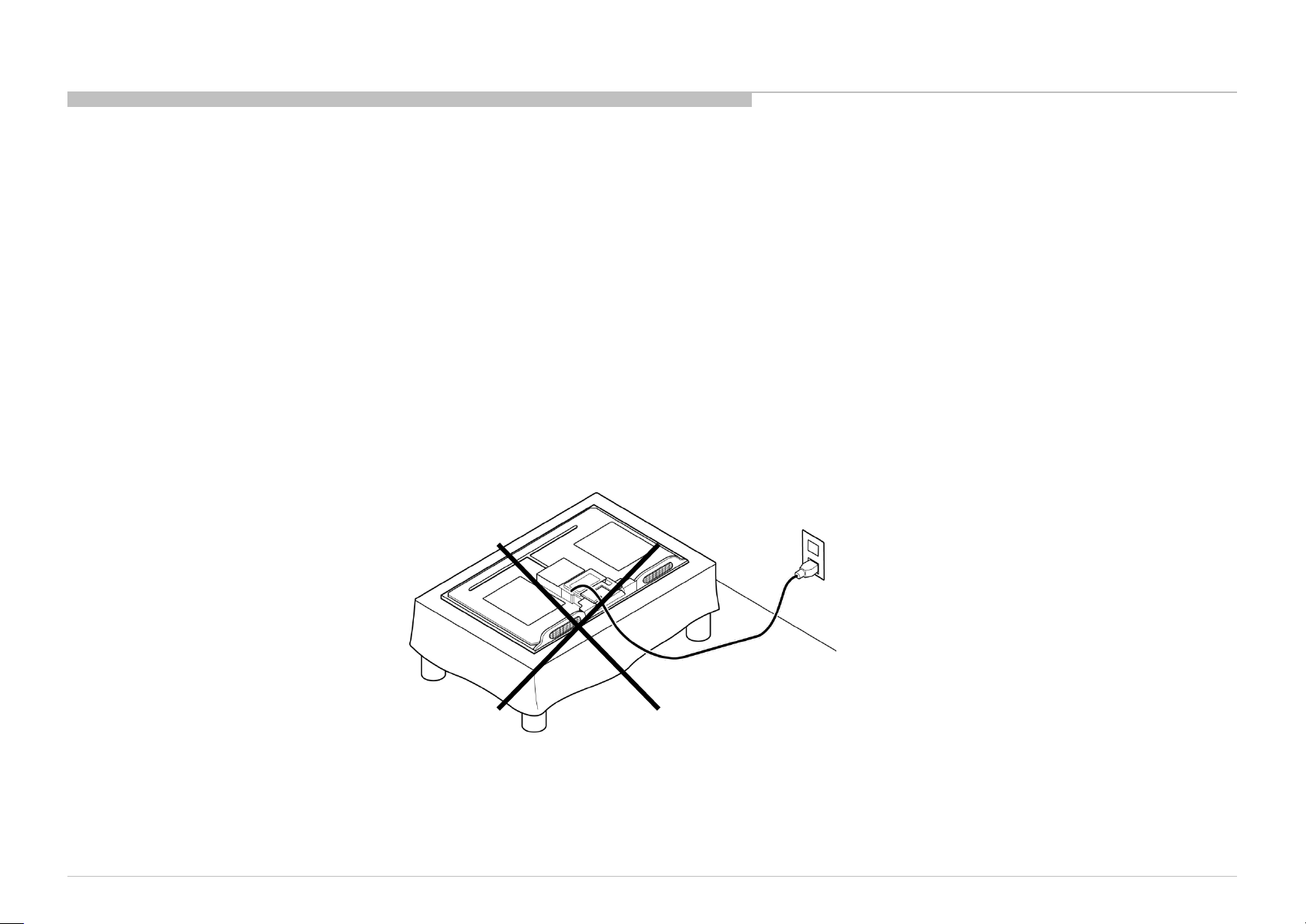
CARRYING THE TV
Be sure to follow these guidelines to protect your property and avoid causing serious injury.
• Carry the TV with an adequate number of people; larger size TVs require two or more people.
• Correct hand placement while carrying the TV is very important for safety and to avoid damages.
SAFETY-RELATED COMPONENT WARNING!!
Components identified by shading and ! mark on the schematic diagrams, exploded views, and in the parts list are critical for safe operation. Replace these components with Sony
parts whose part numbers appear as shown in this manual or in supplements published by Sony. Circuit adjustments that are critical for safe operation are identified in this manual.
Follow these procedures whenever critical components are replaced or improper operation is suspected.
CAUTION ABOUT THE LITHIUM BATTERY
• Danger of explosion if battery is incorrectly replaced. Replace only with the same or equivalent type.
• Outer case broken battery should not contact to water.
KD-65X8000C(CH)
4
Page 5
USE CAUTION WHEN HANDLING THE LCD PANEL
When repairing the LCD panel, be sure you are grounded by using a wrist band.
When repairing the LCD panel on the wall, the LCD panel must be secured using the 4 mounting holes on the rear cover.
1) Do not press on the panel or frame edge to avoid the risk of electric shock.
2) Do not scratch or press on the panel with any sharp objects.
3) Do not leave the module in high temperatures or in areas of high humidity for an extended period of time.
4) Do not expose the LCD panel to direct sunlight.
5) Avoid contact with water. It may cause a short circuit within the module.
6) Disconnect the AC power when replacing the backlight (CCFL) or inverter circuit. (High voltage occurs at the inverter circuit at 650Vrms.)
7) Always clean the LCD panel with a soft cloth material.
8) Use care when handling the wires or connectors of the inverter circuit. Damaging the wires may cause a short.
9) Protect the panel from ESD to avoid damaging the electronic circuit (C-MOS).
10) It is recommended not to exceed 1 hour of Power-On nor Burn-in period with LCD panel face down condition, in repair activity.
WARNINGS AND CAUTIONS
KD-65X8000C(CH)
5
Page 6

SAFETY CHECK-OUT
After correcting the original service problem, perform the following safety checks before releasing the set to the customer:
1. Check the area of your repair for unsoldered or poorly soldered connections. Check the entire board surface for solder splashes and bridges.
2. Check the interboard wiring to ensure that no wires are “pinched” or touching high-wattage resistors.
3. Check that all control knobs, shields, covers, ground straps, and mounting hardware have been replaced. Be absolutely certain that you have replaced all the insulators.
4. Look for unauthorized replacement parts, particularly transistors, that were installed during a previous repair. Point them out to the customer and recommend their replacement.
5. Look for parts which, though functioning, show obvious signs of deterioration. Point them out to the customer and recommend their replacement.
6. Check the line cords for cracks and abrasion. Recommend the replacement of any such line cord to the customer.
7. Check the antenna terminals, metal trim, “metallized” knobs, screws, and all other exposed metal parts for AC leakage. Check leakage as described below.
8. For safety reasons, repairing the Power board and/or Inverter board is prohibited.
KD-65X8000C(CH)
6
Page 7
Leakage Test
The AC leakage from any exposed metal part to earth ground and from all exposed metal parts to any exposed
metal part having a return to chassis, must not exceed 0.5 mA (500 microamperes).
Leakage current can be measured by any one of three methods.
1. A commercial leakage tester, such as the Simpson 229 or RCA WT-540A. Follow the manufacturers’
instructions to use these instructions.
2. A battery-operated AC milliampmeter. The Data Precision 245 digital multimeter is suitable for this job.
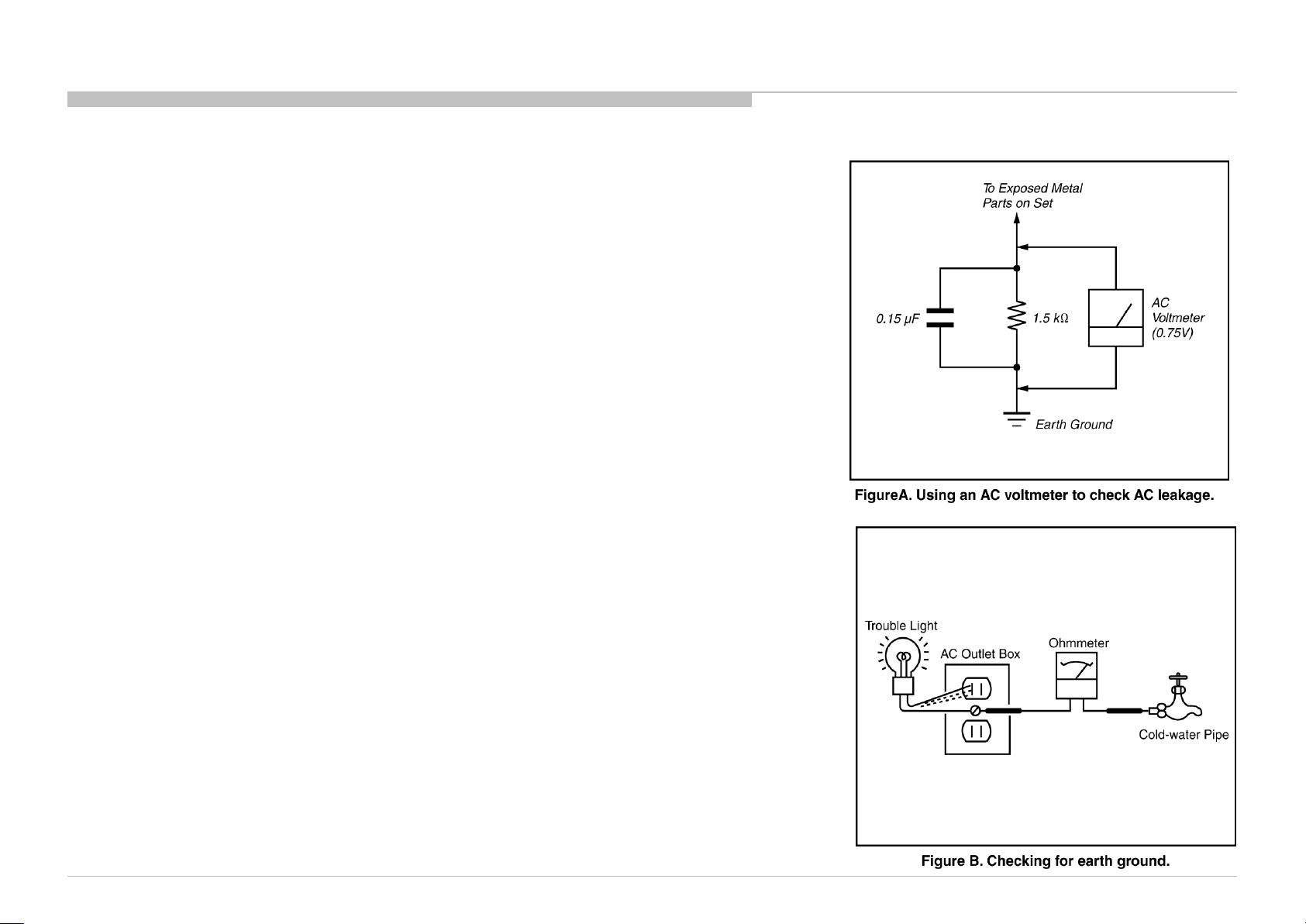
3. Measuring the voltage drop across a resistor by means of a VOM or battery-operated AC voltmeter. The
“limit” indication is 0.75 V, so analog meters must have an accurate low voltage scale.
The Simpson’s 250 and Sanwa SH-63TRD are examples of passive VOMs that are suitable. Nearly all
battery-operated digital multimeters that have a 2 VAC range are suitable (see Figure A).
How to Find a Good Earth Ground
A cold-water pipe is a guaranteed earth ground; the cover-plate retaining screw on most AC outlet boxes is also
at earth ground.
If the retaining screw is to be used as your earth ground, verify that it is at ground by measuring the resistance
between it and a cold-water pipe with an ohmmeter. The reading should be zero ohms.
If a cold-water pipe is not accessible, connect a 60- to 100-watt trouble- light (not a neon lamp) between the hot
side of the receptacle and the retaining screw. Try both slots, if necessary, to locate the hot side on the line; the
lamp should light at normal brilliance if the screw is at ground potential (see Figure B).
SAFETY CHECK-OUT
KD-65X8000C(CH)
7
Page 8
SELF DIAGNOSIS FUNCTION
The units in this manual contain a self-diagnostic function. If an error occurs, the Smart Core Red LED will automatically begin to flash.
The number of times the LED flashes translates to a probable source of the problem.
A definition of the Smart Core Red LED flash indicators is listed in the instruction manual for the user’s knowledge and reference.
If an error symptom cannot be reproduced, the remote commander can be used to review the failure occurrence data stored in memory to reveal past problems and how often these
problems occur.
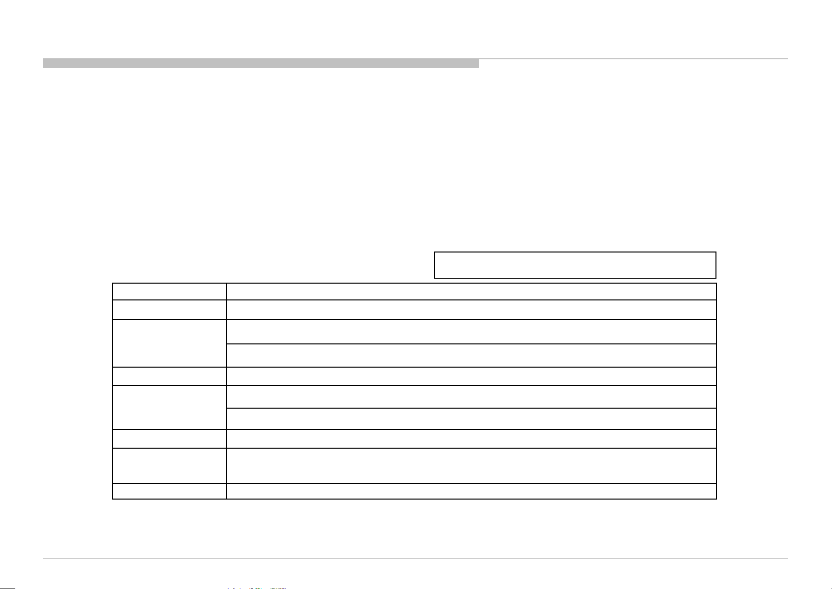
DIAGNOSTIC TEST INDICATORS
When an error occurs, the Smart Core Red LED will flash a set number of times to indicate the possible cause of the problem.
If there is more than one error, the LED will identify the first of the problem areas.
Result for all of the following diagnostic items are displayed on screen.
If the screen displays a “0”, no error has occurred .
<G>: Power supply board, <B>: Main board, <T>: Tcon board,
<P>: Panel module , <S>: Speaker
RED LED blinking count Detection Items
2x
3x
<G/B> Main 12V over voltage [MAIN_POWER]
<B> Main 5.0V failure [DC_ALERT]
<B/S> Audio amp. protection [AUD_ERR]
KD-65X8000C(CH)
4x None
<P/T/G/B> Panel ID EEPROM I2C No ACK (Also panel power failure is a suspect) [P_ID_ERR]
5x
<T> TCon IC I2C communication error [TCON_ERR]
6x <G/P/B> Backlight failure [BACKLIGHT]
Over temperature protection [TEMP_ERR]
7x
8x <B> Software error [SW_ERR]
Red italic: detect at startup sequence only.
<B> Temp. sensor I2C No ACK [TEMP_ERR]
<B> V By One lock error between Main device and 4KBE device [4KBE_ERR]
8
Page 9
SELF DIAGNOSIS FUNCTION
[SELF DIAGNOSTIC SCREEN DISPLAY] [SELF DIAGNOSTIC SCREEN DISPLAY]
Format of error timestamps
YYMMDDhhmmss (in UTC)
Example:
120823132523 -> Aug 23 2012 13:25:23 UTC
* Only when time is set, an error timestamp
is saved.
• Panel Operation Time is recorded every
30 min, but Total Operation Time is recorded every 1 hr.
Therefore, the panel op. time might become larger than
the total op. time.
Total Operation Time [hr] – Boot Count – Panel Operation Time [hr]
" These error item
does not work."
Smart Core Red
LED blinking count
For errors with symptoms such as “power sometimes shuts off” or “screen sometimes goes
out” that cannot be confirmed, it is possible to bring up past occurrences of failure for
confirmation on the screen.
In standby mode, press buttons on the remote commander sequentially in rapid succession
as shown below:
Error item
Naming
SELF CHECK
Back
<<
002 MAIN_POWER 000000000000 000000000000 000000000000 000
003 DC_ALERT 000000000000 000000000000 000000000000 000
003 AUD_ERR 150101000018 150101000018 150101000018 003
003 HDMI_EQ 150101000123 150101000045 150101000045 003
003 TU_DEMOD 150101000218 150101000223 150101000105 003
004 LD_ERR 000000000000 000000000000 000000000000 000
004 BCM_ERR 000000000000 000000000000 000000000000 000
005 TCON_ERR 150101000504 000000000000 000000000000 001
005 P_ID_ERR 000000000000 000000000000 000000000000 000
006 BACKLIGHT ERR 000000000000 000000000000 000000000000 000
007 TEMP_ERR 150101000200 150101000002 000000000000 002
007 4KBE_ERR 000000000000 000000000000 000000000000 000
008 SW_ERR 000000000000 000000000000 000000000000 000
00005 00414 00002
[Home]Exit
Error
timestamp for
last recorded
error
Error
timestamp for
second last
recorded error
Error
timestamp for
3rd last
recorded error
Error count
Since the diagnostic results displayed on the screen are not automatically cleared, always check the self-diagnostic screen.
After you have completed the repairs, clear the result display to “0”.
Clearing the Self Check Diagnostic List
Panel operation time : Press the Channel 7 => Channel 0 .
To exit the Self Diagnostic screen...
NOTE:
This model does not have the function to clear the error history of self-diagnostic screen
by remote such as press the Channel 8 => Channel 0.
If you want to finish service mode app, do AC OFF/ON
→*Service mode app is disable perfectly if you want to move home menu, push <HOME>button
→*Service mode app do background(not disable perfectly)
KD-65X8000C(CH)
9
Page 10
SEC 1. DISASSEMBLY
• There are clutch in the yellow frame[ ]. Therefore please be careful in the case of the disassembly or assembly of parts.
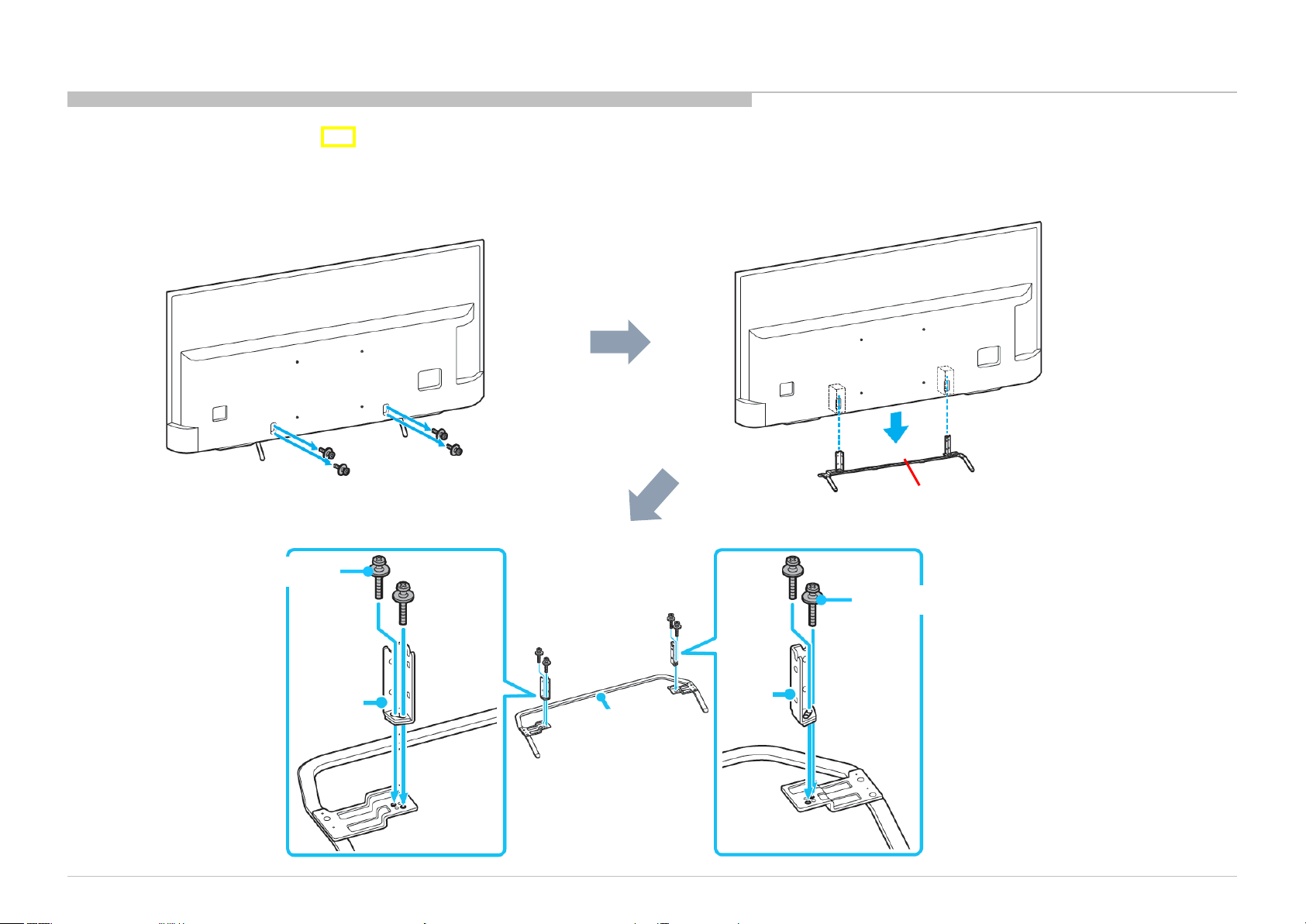
1-1. KD-65X8000C
1-1-1. STAND AND NECK
4 screws (SCREW, +PSW M5X12) P/N: 2-580-607-01
2 screws ( SCREW, +PSW M5X20)
KD-65X8000C(CH)
NECK
STAND
2 screws ( SCREW, +PSW M5X20)
NECK
STAND,
SHAFT (2L SWN) A
These screws are included in BAG,
SCREW (2L SWN). P/N: 4-570-853-01
10
Page 11
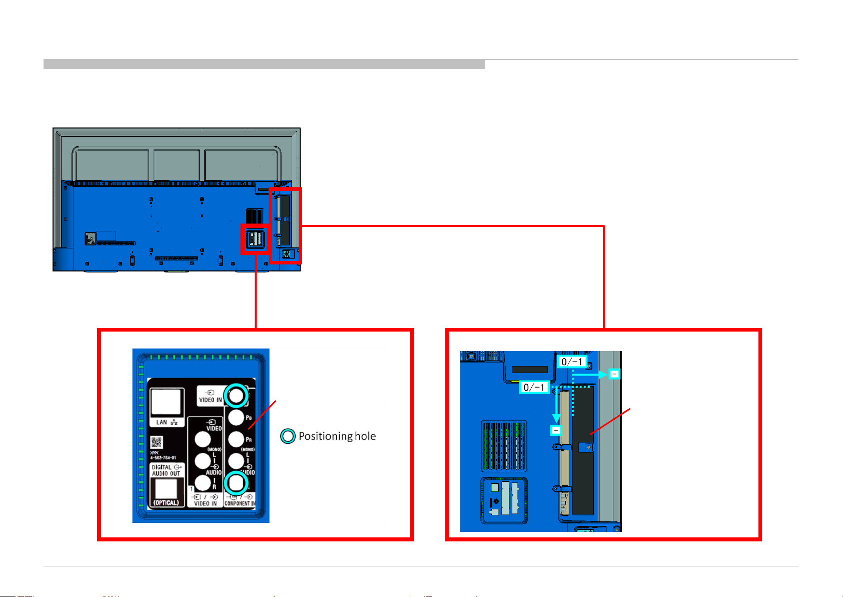
1-1. KD-65X8000C
1-1-2. LABEL, REAR TERMINAL AND LABEL, SIDE TERMINAL (W)
DISASSEMBLY
KD-65X8000C(CH)
LABEL, REAR TERMINAL
LABEL, SIDE TERMINAL (W)
11
Page 12
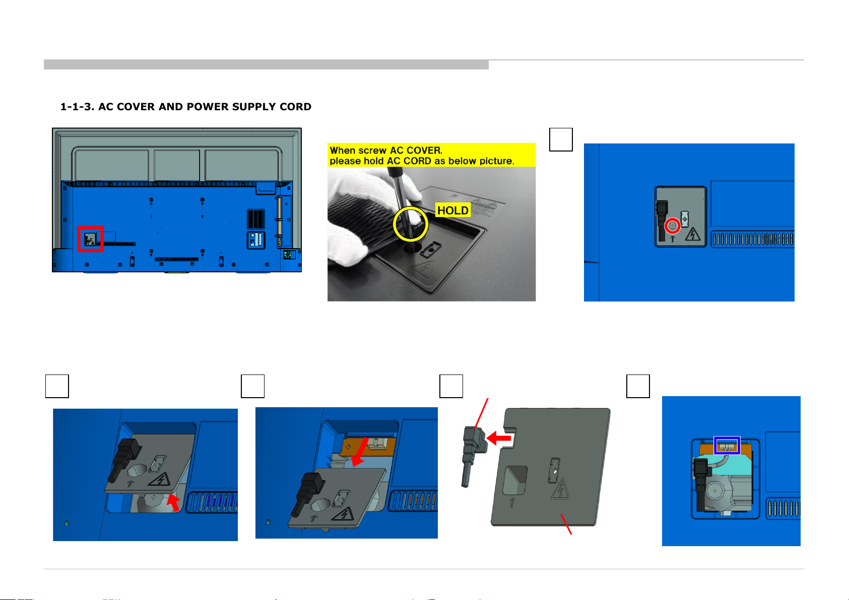
1-1. KD-65X8000C
1-1-3. AC COVER AND POWER SUPPLY CORD
DISASSEMBLY
1
Screw (SCREW, +PSW M4X10) P/N: 4-159-298-01
2 3 4
KD-65X8000C(CH)
POWER SUPPLY CORD
AC COVER
5
12
Page 13
1-1. KD-65X8000C
1-1-4. COVER, REAR (2L SWN) A
1
7 screws (SCREW, +BVTP 4X12 TYPE2 IT-3) P/N: 2-580-639-01
6 screws (SCREW, +PSW M4X10) P/N: 4-159-298-01
12 screws (SCREW, +PWH M3X6) P/N: 4-452-935-11
DISASSEMBLY
COVER, REAR (2L SWN) A
2
NOTE:
KD-65X8000C(CH)
13
Page 14
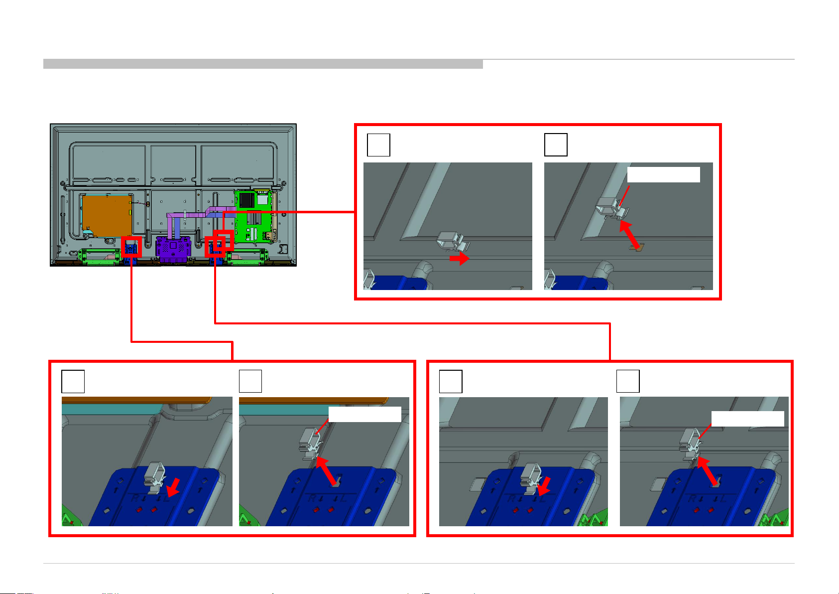
1-1. KD-65X8000C
1-1-5. TAPE
DISASSEMBLY
TAPE
KD-65X8000C(CH)
TAPE
14
Page 15
1-1. KD-65X8000C
1-1-6. TAPE AND WIRE DRESSING
DISASSEMBLY
KD-65X8000C(CH)
TAPE
TAPE
TAPE
15
Page 16
1-1. KD-65X8000C
1-1-7. TAPE
DISASSEMBLY
TAPE
KD-65X8000C(CH)
TAPE
TAPE
TAPE (DK020FR-19) 19X50 SHEET
16
Page 17
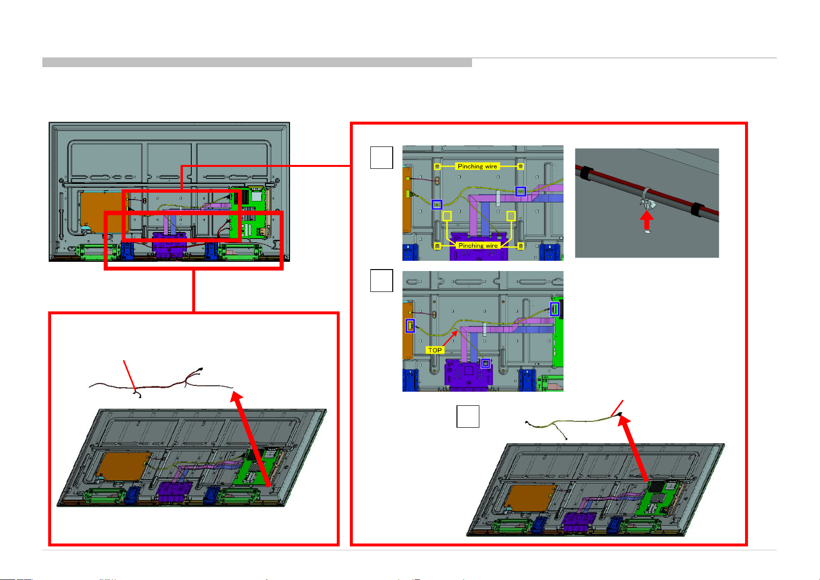
1-1. KD-65X8000C
1-1-8. WIRE DRESSING
DISASSEMBLY
KD-65X8000C(CH)
17
Page 18
1-1. KD-65X8000C
1-1-9. SPEAKER BOX ASSY (L)
2 3
DISASSEMBLY
1
KD-65X8000C(CH)
SPEAKER BOX ASSY (L)
18
Page 19
1-1. KD-65X8000C
1-1-10. SPEAKER BOX ASSY (R)
2 3
DISASSEMBLY
1
KD-65X8000C(CH)
SPEAKER BOX ASSY (R)
19
Page 20
1-1. KD-65X8000C
1-1-11. BT ANTENNA
2 3
DISASSEMBLY
1
Screw (SCREW (+PSW) (M3X6)) P/N: 2-990-421-41
KD-65X8000C(CH)
BT ANTENNA
20
Page 21
1-1. KD-65X8000C
1-1-12. SMART CORE
DISASSEMBLY
NOTE:
1
2
SMART CORE
KD-65X8000C(CH)
21
Page 22
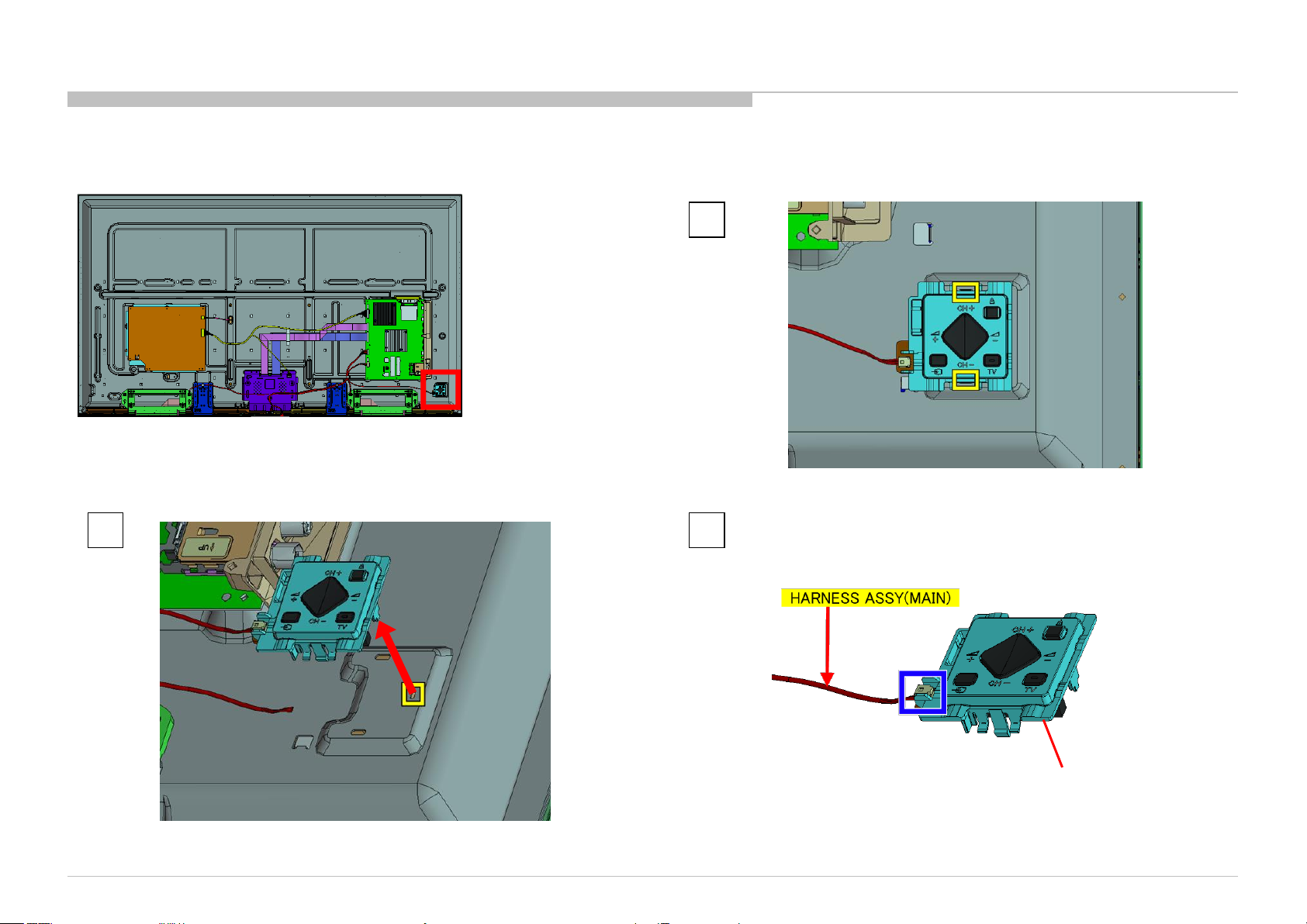
1-1. KD-65X8000C
1-1-13. SWITCH UNIT
2 3
DISASSEMBLY
1
KD-65X8000C(CH)
SWITCH UNIT
22
Page 23
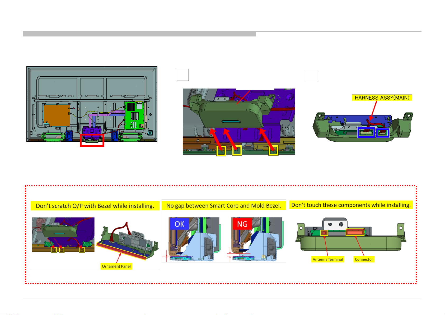
1-1. KD-65X8000C
1-1-14. HARNESS ASSY (MAIN) AND CONNECTOR ASSY 28P
DISASSEMBLY
1
2
HARNESS ASSY(MAIN)
P/N: 1-910-110-66
KD-65X8000C(CH)
CONNECTOR ASSY 28P
P/N: 1-910-110-65
3
23
Page 24
1-1. KD-65X8000C
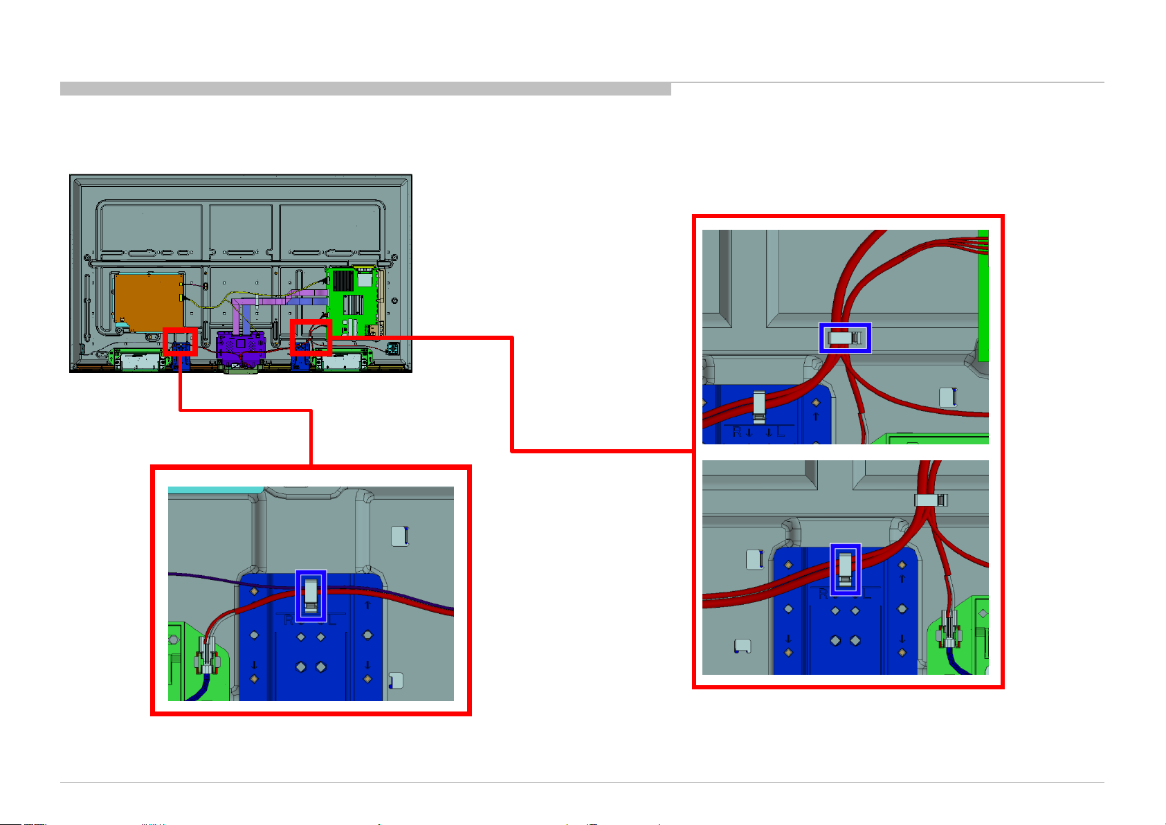
1-1-15. SLIDE, CLAMP
DISASSEMBLY
1
2
1
SLIDE, CLAMP
SLIDE, CLAMP
1
2
SLIDE, CLAMP
2
SLIDE, CLAMP
KD-65X8000C(CH)
24
Page 25
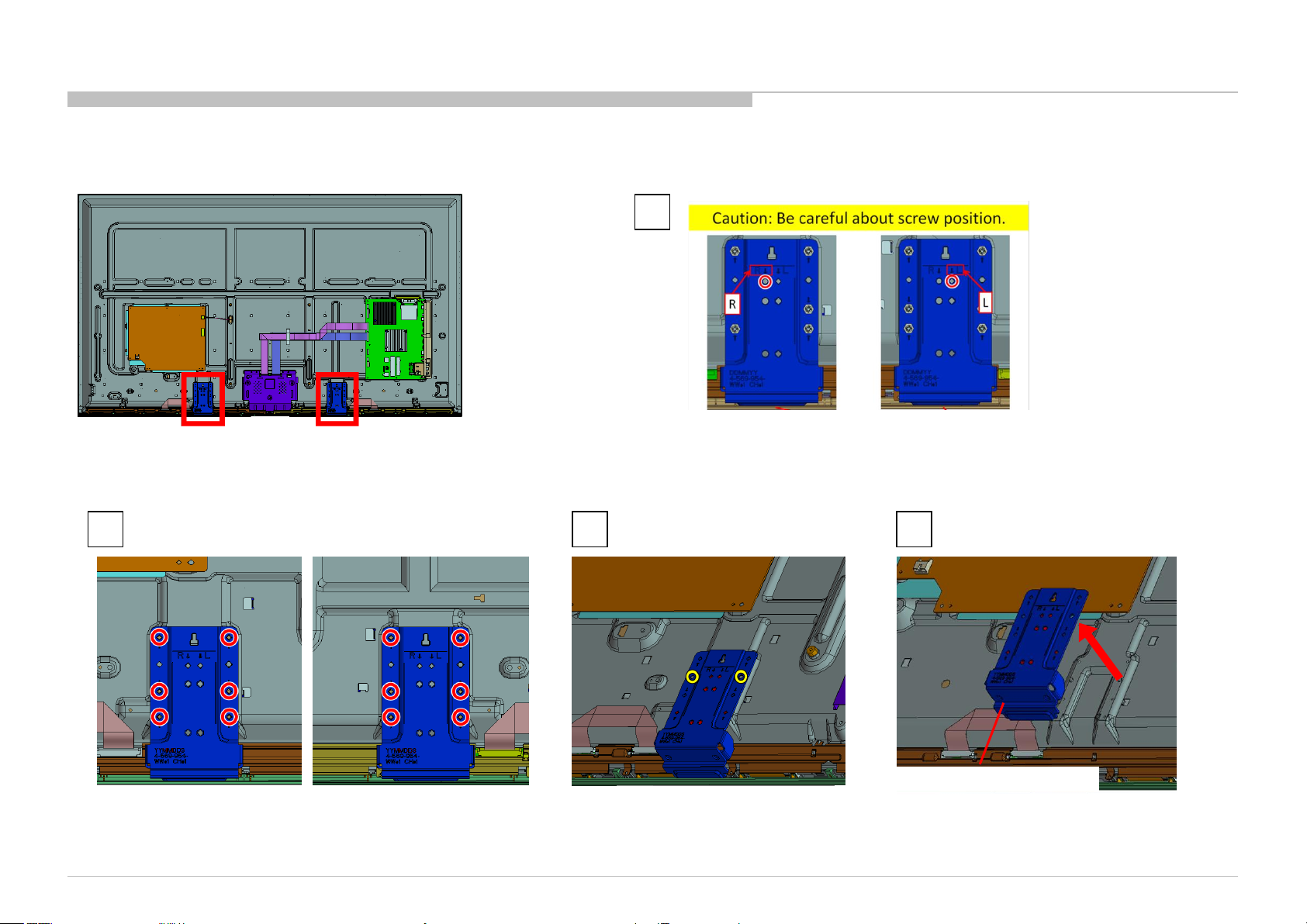
1-1. KD-65X8000C
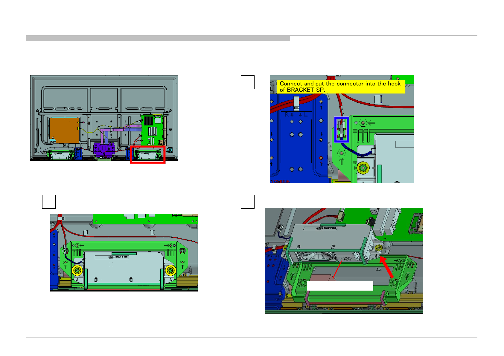
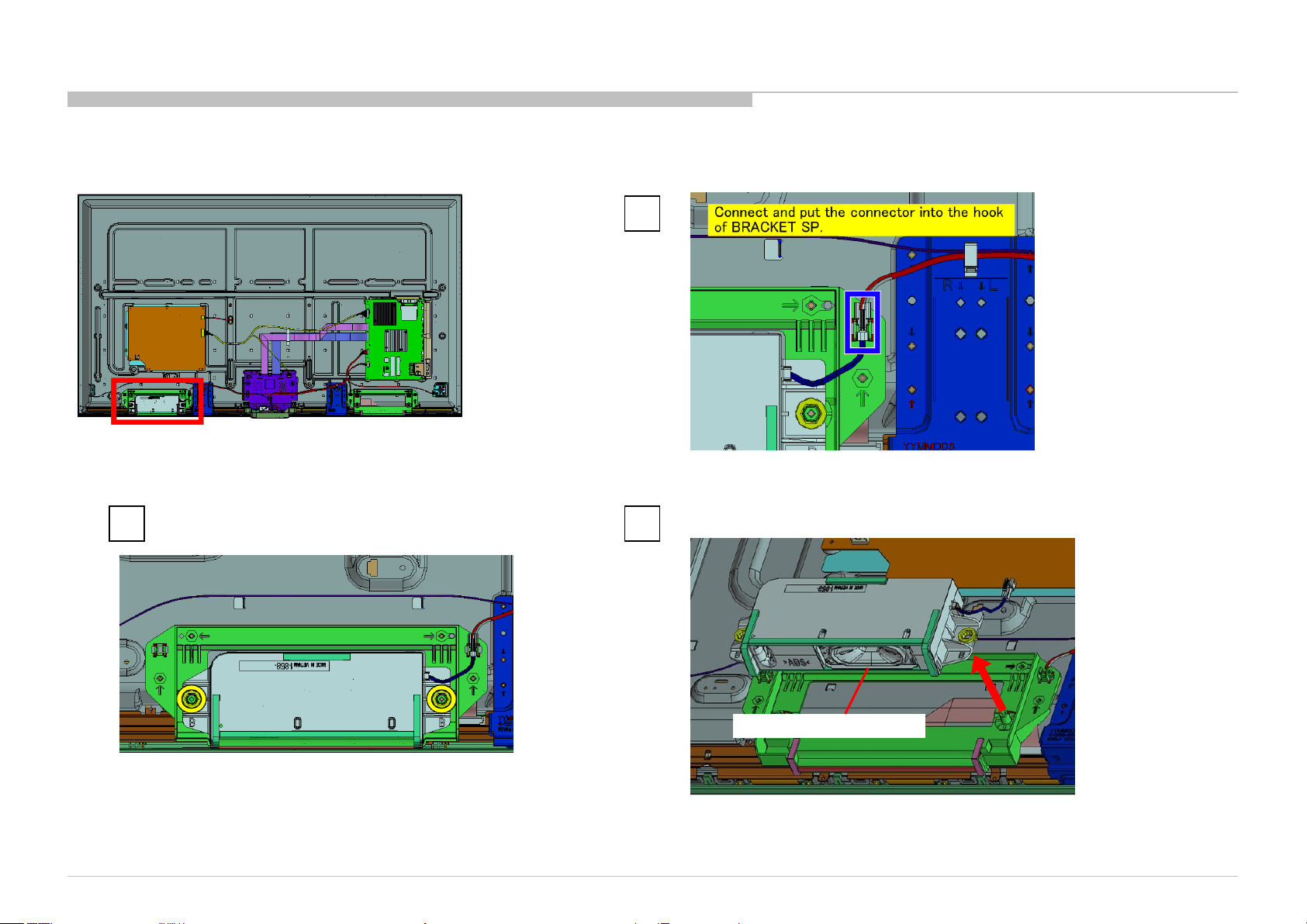
1-1-16. BRACKET, SP (2L SWN) A
DISASSEMBLY
1
4 screws (SCREW, +PSW M3X8) P/N: 2-580-593-01
2
3
1
4 screws (SCREW, +PSW M3X8) P/N: 2-580-593-01
2
3
BRACKET, SP (2L SWN) A
KD-65X8000C(CH)
BRACKET, SP (2L SWN) A
25
Page 26
1-1. KD-65X8000C
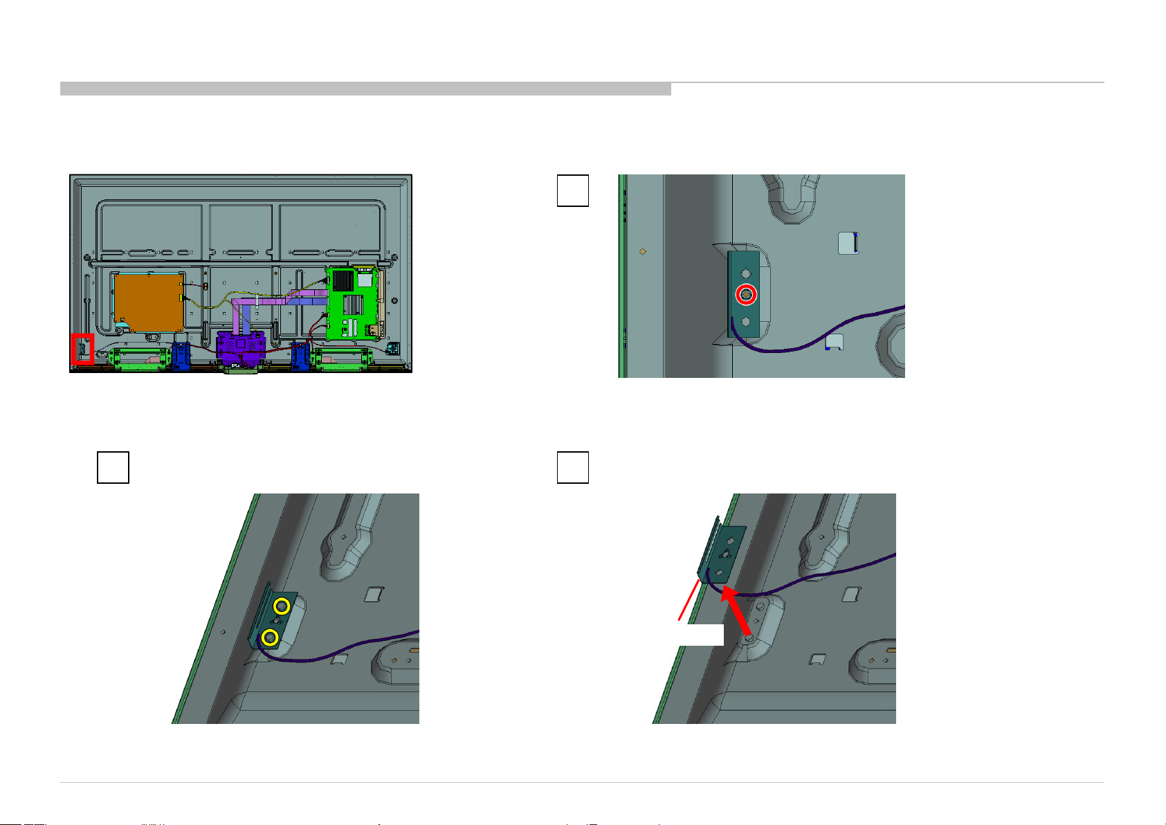
1-1-17. BRACKET, STAND (2L SWN)
1
2 screws (PULLEY, STAND (HWI)) P/N: 4-534-964-01
2 3 4
DISASSEMBLY
12 screws (SCREW, +PSW M3X8) P/N: 2-580-593-01
KD-65X8000C(CH)
BRACKET, STAND (2L SWN)
26
Page 27
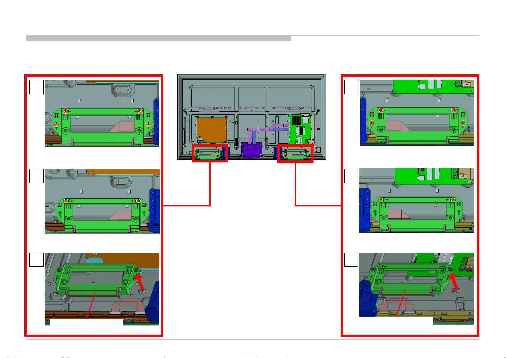
1-1. KD-65X8000C
1-1-18. GL6
DISASSEMBLY
1
6 screws (SCREW, +PSW M3X6 W12) P/N: 4-256-393-12
KD-65X8000C(CH)
3 2
4
GL6
27
Page 28
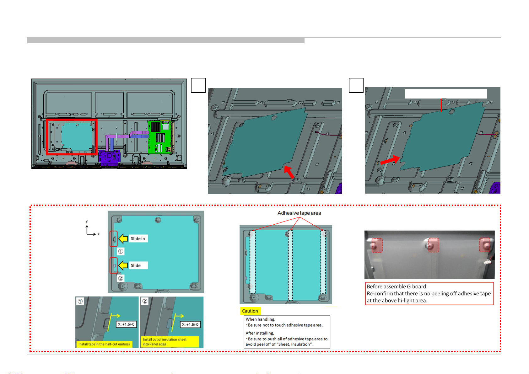
1-1. KD-65X8000C
1-1-19. SHEET, INSULATION(HRN L)
NOTE:
DISASSEMBLY
1 2
SHEET, INSULATION (HRN L)
KD-65X8000C(CH)
28
Page 29
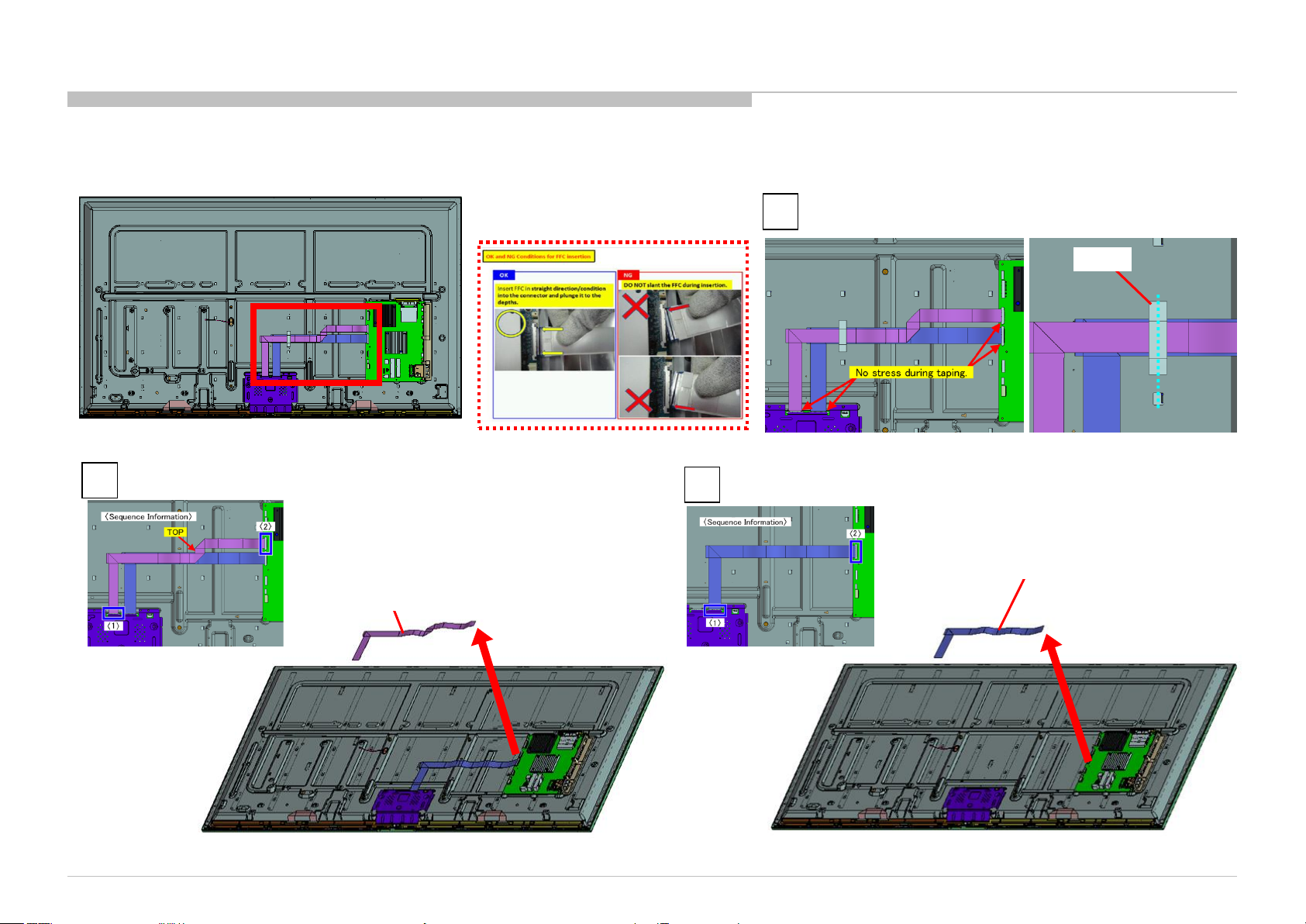
1-1. KD-65X8000C
1-1-20. TAPE AND FLEXIBLE FLAT CABLE 41P (XFF) AND FLEXIBLE FLAT CABLE 51P (XFF)
1
DISASSEMBLY
TAPE
2
KD-65X8000C(CH)
3
FLEXIBLE FLAT CABLE 51P (XFF)
P/N: 1-849-079-11
FLEXIBLE FLAT CABLE 41P (XFF)
P/N: 1-849-078-11
29
Page 30
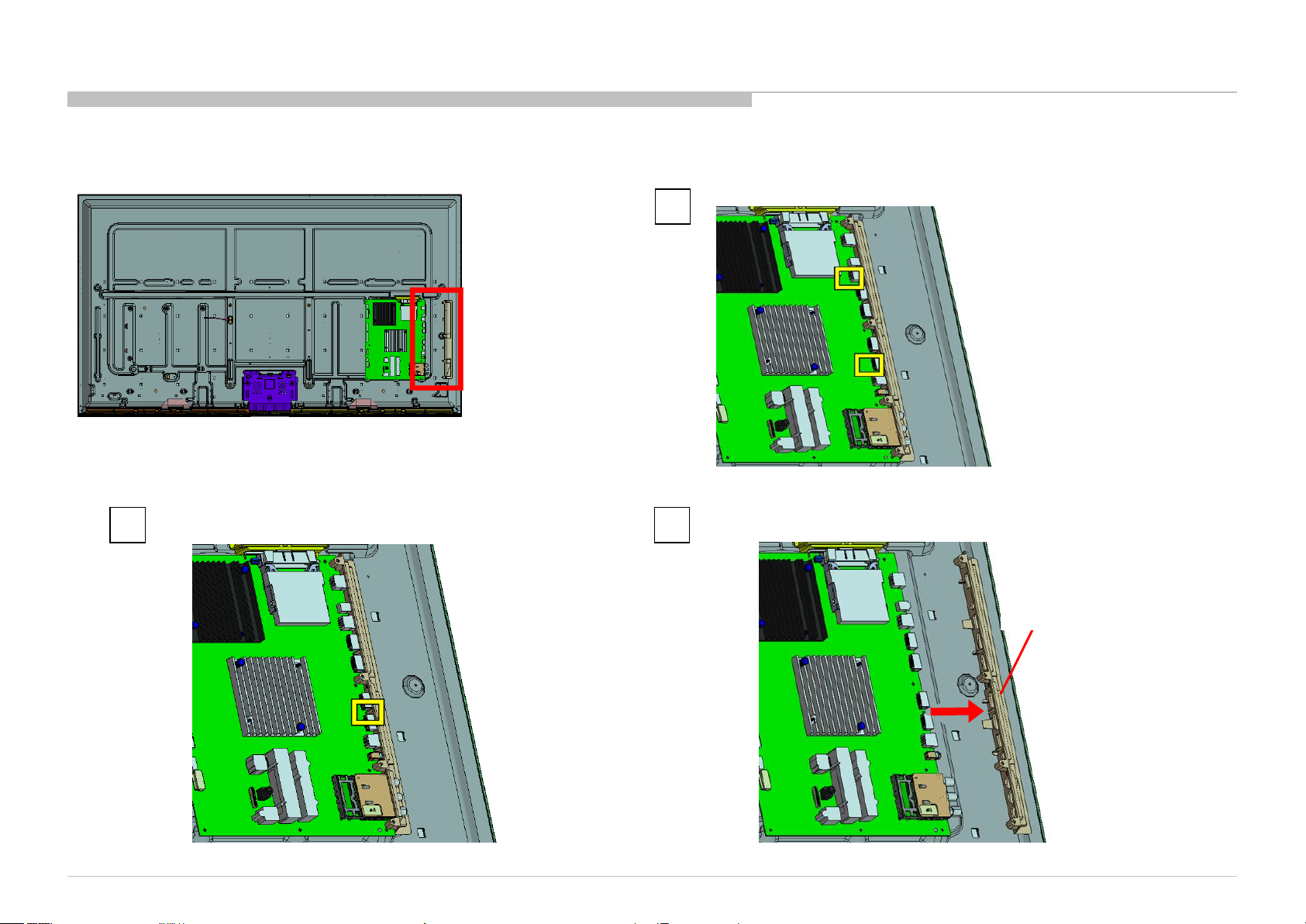
1-1. KD-65X8000C
1-1-21. BRACKET, SIDE F (MOLD)
2 3
DISASSEMBLY
1
KD-65X8000C(CH)
BRACKET, SIDE F (MOLD)
30
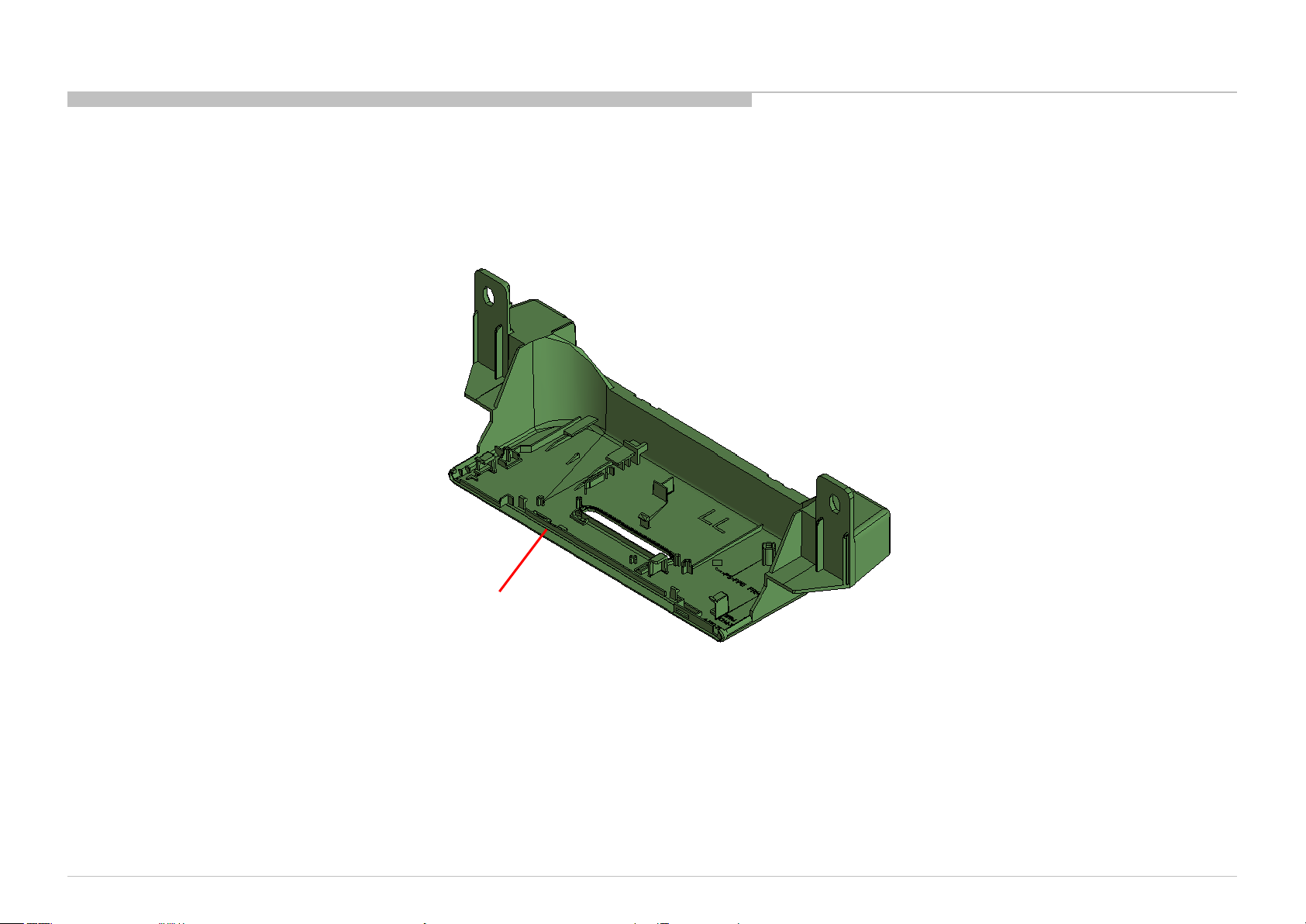
Page 31

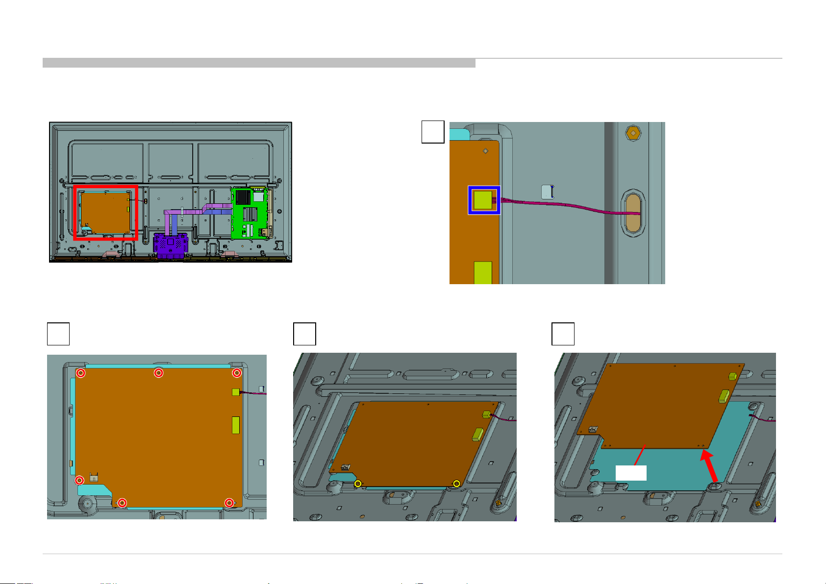
1-1. KD-65X8000C
1-1-22. BMFW
2 3
DISASSEMBLY
1
8 screws (SCREW (+PSW) (M3X6)) P/N: 2-990-421-41
KD-65X8000C(CH)
BMFW
31
Page 32

1-1. KD-65X8000C
DISASSEMBLY
1-1-23. GASKET (BMF)
Five attachment positions of Gasket BMFW B-Side view
PWB P/N indication location
KD-65X8000C(CH)
NOTE:
When you replace a BMFW board, it is necessary to stick five new GASKET on a new BMFW board.
GASKET (BMF): 4-566-117-01
However, please confirm PWB P/N before that.
If the PWB P/N is old type(1-894-595-11/21), need gaskets.
If the PWB P/N is new type(suffix -12/22 or later), no need gaskets.
*There is no problem even if you were mounting a gasket on new type(suffix -12/22 or later).
32
Page 33

1-1. KD-65X8000C
1-1-24. SHEET, THERMAL(BM) AND PLATE, MAIN S (HRN)
1
DISASSEMBLY
NOTE:
SHEET, THERMAL (BM)
2 3 4
2 screws (SCREW (+PSW) (M3X6)) P/N: 2-990-421-41
KD-65X8000C(CH)
PLATE, MAIN S (HRN)
33
Page 34

1-1. KD-65X8000C
1-1-25. LCD PANEL
DISASSEMBLY
LCD PANEL
NOTE:
KD-65X8000C(CH)
34
Page 35

1-2. SMART CORE
1-2-1. BRACKET, WIFI ASSY
DISASSEMBLY
1
2
KD-65X8000C(CH)
3
BRACKET, WIFI ASSY
35
Page 36

1-2. SMART CORE
1-2-2. WLAN / BT MODULE(11AC) ASSY
DISASSEMBLY
3
2
1
2
NOTE:
KD-65X8000C(CH)
1
WLAN / BT MODULE(11AC) ASSY
36
Page 37

1-2. SMART CORE
1-2-3. SHEET, THERMAL (SC) AND WLAN / BT MODULE(11AC)
SHEET, THERMAL (SC)
Opposite side of WLAN / BT MODULE (11AC) ASSY
DISASSEMBLY
WLAN / BT MODULE(11AC)
1-2-4. HEAT SINK (SC) AND BRACKET, WIFI
KD-65X8000C(CH)
HEAT SINK (SC)
1 2
BRACKET, WIFI
37
Page 38

1-2. SMART CORE
1-2-5. COVER, TOP
DISASSEMBLY
NOTE:
1
KD-65X8000C(CH)
2
COVER, TOP
38
Page 39

1-2. SMART CORE
1-2-6. PANEL, ORNAMENT
DISASSEMBLY
1
2 3
KD-65X8000C(CH)
1
PANEL, ORNAMENT
2
39
Page 40

1-2. SMART CORE
1-2-7. LIGHT, GUIDE
DISASSEMBLY
1
KD-65X8000C(CH)
2 3
LIGHT, GUIDE
LOCK PORTION
40
Page 41

1-2. SMART CORE
1-2-8. HSC3_L MOUNT
DISASSEMBLY
3
1
2
NOTE:
HSC3_L MOUNT
KD-65X8000C(CH)
41
Page 42
1-2. SMART CORE
1-2-9. CASE, BOTTOM (LL)
DISASSEMBLY
KD-65X8000C(CH)
CASE, BOTTOM (LL)
42
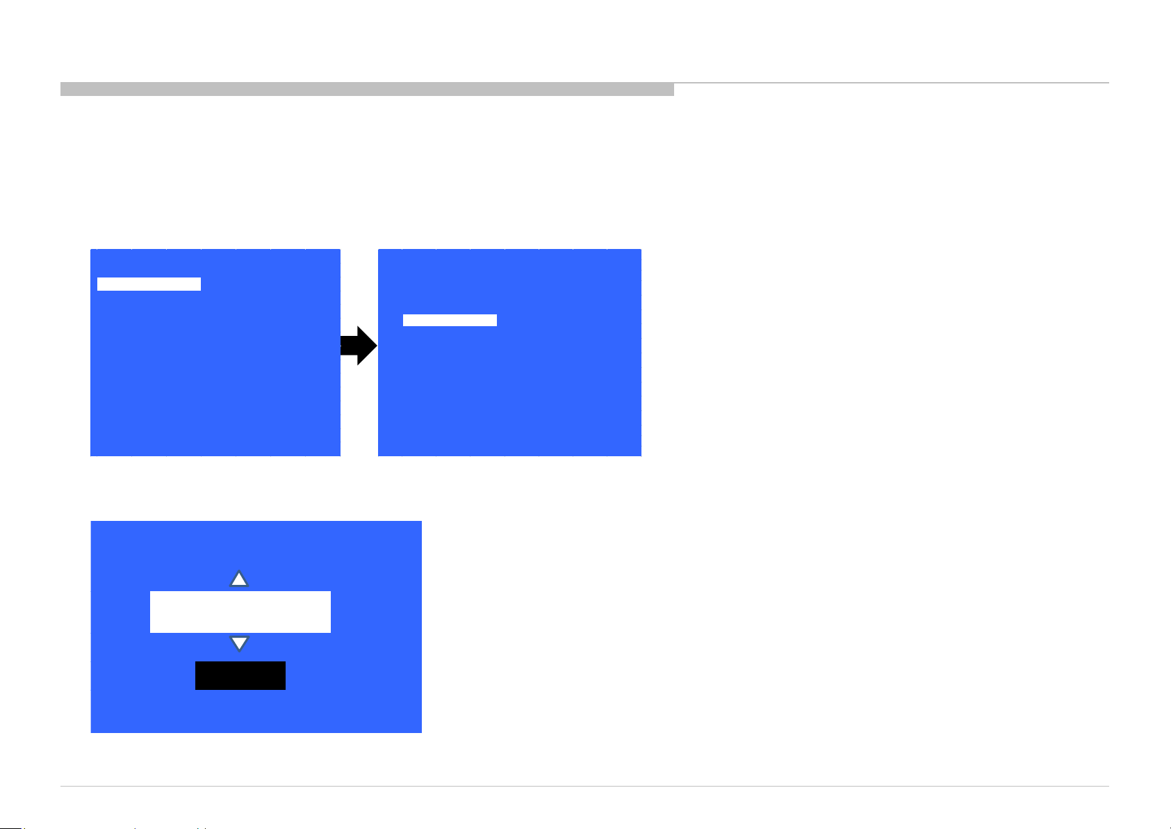
Page 43

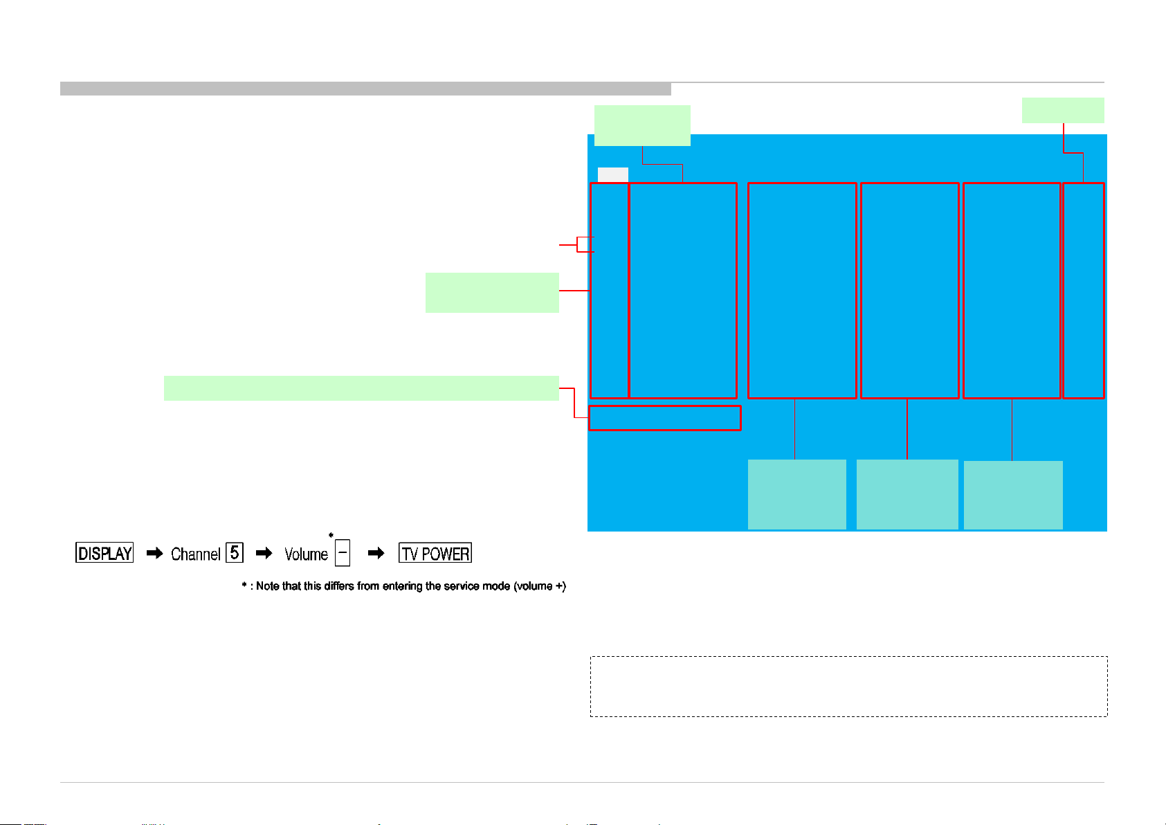
SEC 2. ADJUSTMENT
HOW TO ENTERING SERVICE MODE
1) Turn on the main power switch to place the set in standby mode.
2) Press the buttons on the remote commander as follows, and entering service mode.
3) Service mode display.
Service Mode
Model Information
Self diagnosis History
Video / Audio
Panel / PQ
General Setting
Tuner
Wifi
>>
>>
>>
>>
>>
>>
>>
[</>] Set [Home]Exit
4) How to use the remote commander.
Function The flow of control
Service mode on <Display><5><Vol Up><Power>
Service mode off <MENU>/<HOME>
Item up / down
Item select left/right <←>/<→>
Execute <OK>
5) When finished the operation of service mode , please AC Plug OFF/ON the TV set.
(*If you don’t do AC plug OFF/ON, remain the Service Mode App and User can see the Service Mode after RC ON.)
KD-65X8000C(CH)
<↑>/ <↓>
43
Page 44

SOFTWARE VERSION
>>
Model Information
>>
Model Number Setting
>>
SERIAL NUMBER EDIT
[</>] Set [Home]Exit
Model
Status Inf ormation
1) In Service Mode, select “Model Information”, press “Enter” or “→” button to enter Status Information.
ADJUSTMENT
Model Information
Self diagnosis History
Video / Audio
Panel / PQ
General Setting
Tuner
Wifi
Service Mode
>>
>>
>>
>>
>>
>>
>>
[</>] Set [Home]Exit
2) Press “Enter” or “Return” button to return to Service Mode.
Service Mode
Model Information
Self diagnosis History
Video / Audio
Panel / PQ
General Setting
Tuner
Wifi
>>
>>
>>
>>
>>
>>
>>
>>
Main Micro
SW Version:
NVM Version:
Boot Version:
PQ Version:
AQ Version:
<Ext>
exFRC:
CameraVID:
CameraPIC:
CameraFW:
4k BE
MLFW:
MAFW:
ADSP
NDAT
PDAT
BDAT
BCM
FDAT
UDAT
BDIX
PKG2.011.0010NAB
0001 UC2
V1.000
102100006
AQ1.100
00.00.00.00
0
0
0
SF1.002
SF0.360
SF0.501
SD0.370
SD0.370
SD1.011
SD------SD0.002
SD0.000
SD0.370
KD-65X8000C(CH)
[</>] Set [Home]Exit
44
Page 45

SERIAL NUMBER EDIT (1)
ADJUSTMENT
1) In “Service Mode”, select “Model Information” by pressing “↑” or “↓” then pressing “Enter” or
“→” button to enter inside.
2) Select “Serial Number Edit” by pressing “↑” or “↓” button then pressing “Enter” or “→” button
3) Press “↑” or “↓” to input numbers.
4) After user input data , press <Enter> .
• Pop-up dialog appear to confirm input data correct
• Serial Number can be set ONLY ONCE
5) Press “→” or “←” button to select YES or NO.
Select YES if input data is correct.
Select NO if input data is incorrect.
Press <Enter> to save answer.
Model Information
Self diagnosis History
Video / Audio
Panel / PQ
General Setting
Tuner
Wifi
Status Information
Model Information
Model Number Setting
Serial Number Edit
Status Information
Model Information
Model Number Setting
Serial Number Edit
Service Mode
>>
>>
>>
>>
>>
>>
>>
[</>] Set [Home]Exit
Mode
Service Mode
>>
>>
>>
_ _ _ _ _ _ _
>>
>>
>>
9 9 9 9 9 9 9
KD-65X8000C(CH)
Input Data correct?
Yes No
45
Page 46

SERIAL NUMBER EDIT (2)
Yes No
Input Data correct?
ADJUSTMENT
If YES is selected, the input data is saved into EEPROM.
SERIAL NUMBER EDIT is greyed out and the serial number that has been input is displayed.
User will not able to edit anymore.
If NO is selected, the input data is not saved into EEPROM.
The serial number that has been input is displayed.
User can still edit the Serial Number.
Status Information
Model Information
Model Number Setting
Serial Number Edit
Status Information
Model Information
Model Number Setting
Serial Number Edit
Service Mode
<[ ]>
Service Mode
<[ ]>
>>
>>
KDL-40X500B
9 9 9 9 9 9 9
>>
>>
KDL-40X500B
9 9 9 9 9 9 9
KD-65X8000C(CH)
46
Page 47
MODEL NUMBER SETTING
_ _ _ _ _ _ _ _ _ _ _ _
OK
[MODEL_NUMBER_SETTING]
1) In “Service Mode”, select “Model Information” by pressing “↑” or “↓” then pressing “Enter” or “→” button to enter inside.
2) Select “Model Number Setting” by pressing “↑” or “↓” button then pressing “Enter” or “→” button.
3) Press “↑” or “↓” arrow key to scroll Product Name Candidate.
(e.g. KDL-40X500B CO1,KDL-40X500C BR6)
ADJUSTMENT
Service Mode
Model Information
Self diagnosis History
Video / Audio
Panel / PQ
General Setting
Tuner
Wifi
>>
>>
>>
>>
>>
>>
>>
Status Information
Model Information
Model Number Setting
Serial Number Edit
Service Mode
>>
>>
>>
>>
[</>] Set [Home]Exit
4) Select one Product Name from the list, press <Enter> will pop dialog to inform user to confirm data. Model dependent settings will be overwritten into EEPROM.
KD-65X8000C(CH)
47
Page 48

ADJUSTMENT
Back
R WB Gain
<[ 0 ]>
G WB Gai n
<[ 0 ]>
B WB Gain
<[ 0 ]>
R WB Offs et
<[ 0 ]>
G WB Offs et
<[ 0 ]>
B WB Offs et
<[ 0 ]>
<<
[</>] Set [Home]Exit
>>
>>
>>
>>
>>
>>
>>
Service Mode
Tuner
Wifi / BT
Model Information
Self diagnosis History
Video / Audio
Panel / PQ
General Setting
WB ADJUSTMENT
(Please apply Main board or panel is replaced.)
In “Panel/PQ” service mode.
a. Go to “WB Adjustment” category by “↑” or “↓”.
b. To select “WB Adjustment”, press “→” button.
c. To change data , press “←” or “→” on remote commander.
KD-65X8000C(CH)
48
Page 49

ADJUSTMENT
>>
>>
>>
>>
>>
>>
>>
Service Mode
Tuner
Wifi / BT
Model Information
Self diagnosis History
Video / Audio
Panel / PQ
General Setting
Back
<<
<[ 0. SoC to T-con ]>
Mura data transfer
<[ 0. SoC to T-con ]>
CUC data trans fer
<[ 0. SoC to T-con ]>
[Start]
[</>] Set [Home]Exit
WB/Gamma data trans fer
WB/MURA/CUC DATA TRANSFER
(Please apply Main board or panel is replaced.)
1. In “Panel/PQ” service mode.
a. Go to “WB/Mura/CUC data transfer” category by “↑” or “↓”.
b. To select “WB/Mura/CUC data transfer”, press “→” button.
c. To change data , press “←” or “→” on remote commander.
2. In “WB/Mura/CUC data transfer”.
a. Select “WB/Gamma data transfer” by pressing “↑” or “↓” on remote commander.
b. To change the items, press “←” or “→” on remote commander and press “Enter”
button.
Selectable items are:
0. SoC to T-con
1. T-con to SoC
2. Not atction
c. Select “[start]” and press “Enter” button to start transfer.
KD-65X8000C(CH)
49
Page 50

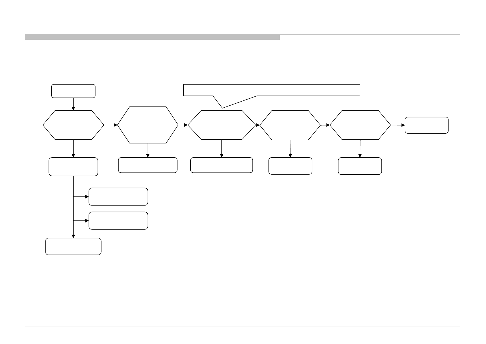
SEC 3. TROUBLE SHOOTING
Bluetooth
Power LED
not
response to
Stationary
colored
lines or
dots
No video One
No video all
Smart Core no
Bluetooth /
) can't
Wifi & BT Module
(Communi
TEMP
Software
Emitter
Local
UART
3-1. TRIAGE
1. Confirm the claimed symptom.
2. Select that symptom from the chart.
3. Bring all the boards and cables listed for that symptom.
4. Follow the troubleshooting charts in the technical guides to isolate the board.
5. Chart Color Code.
RED DOT: Most likely defective part
BLUE TRIANGLE: Secondary possible defective part
BLACK TEXT: Board that may correct the symptom
Reference
B* Board
G* Board
H* Board
K* Board
Speaker
LD* Board
V By One FFC
Tcon
LCD Panel
Problem
Symptoms - Shutdown. Power LED
blinking red diagnostics sequences
2 3 4 5 6 7 8 9 10
p l p
l p p
p
p
Power Power LD
Audio
Local
I2C
p p l l
p l
l
p
p
l
l l p
Panel
cation)
Panel
(Backlight)
l
p
No
Power
No White
& does
remote
(Dead Set)
p p l l p p l p p p
l
p
p
p
l
Video
- missing or distorted
of Inputs
Inputs
p
p
p
p
Remote Network Audio Skype Smart Core
No Remote
l
Wireless
can't connect
l
No Audio
p
l
l
Skype
Can't Work
p
LED (Set is still
alive)
l
(BT)
One Step
Remote
(OSR
connect
l
KD-65X8000C(CH)
50
Page 51

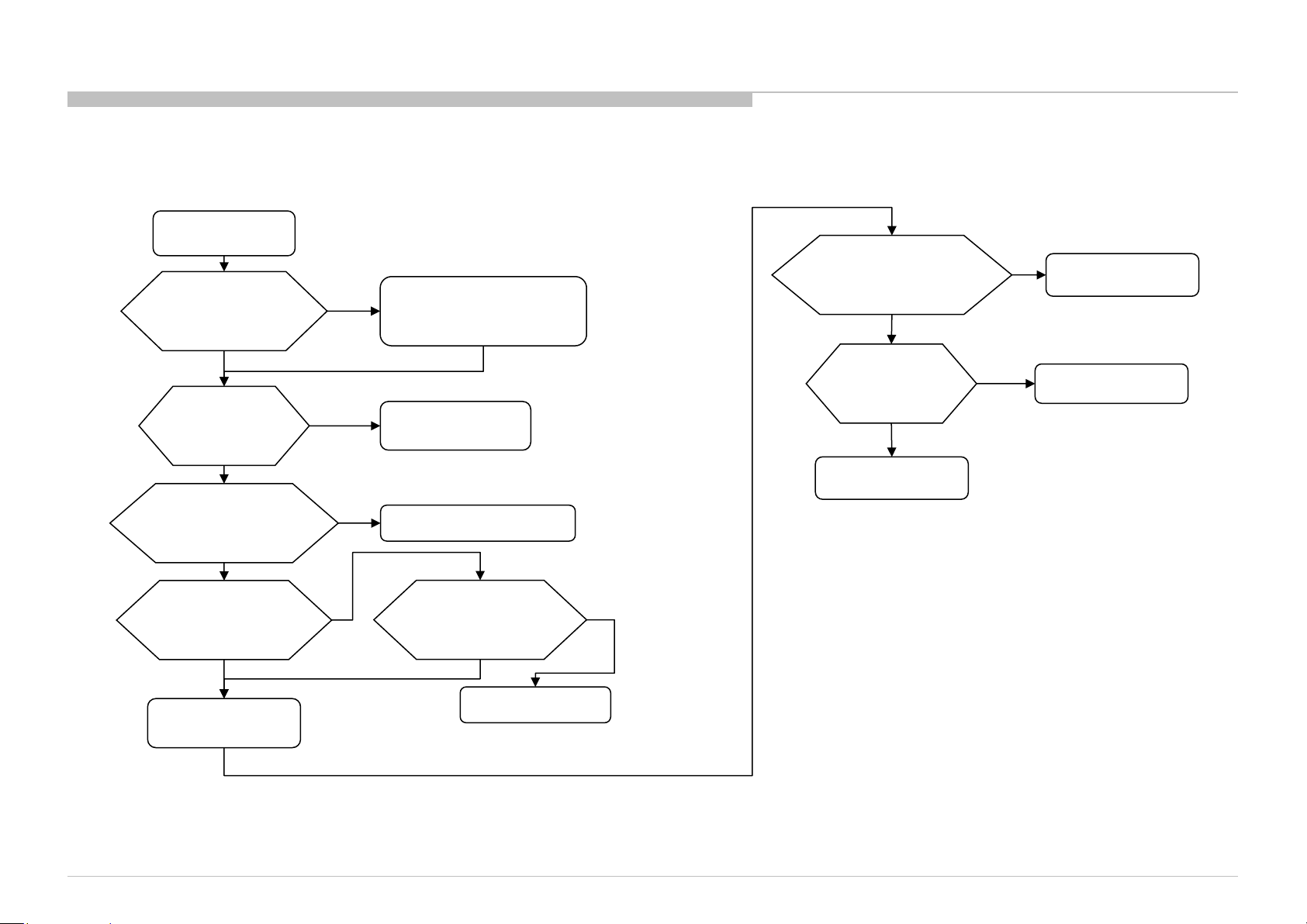
3-2. NO POWER
3-2-1. NO POWER-PCU
No Power
TROUBLE SHOOTING
Check STBY 3.3V
C9030
On B* board
OK
B* Board
NG
Replace
Between G* Board to
B* Board Harness
OK
Harness
u-Com Failure
DDCON/LDO
Main Device Failure
NG
G* Board
KD-65X8000C(CH)
51
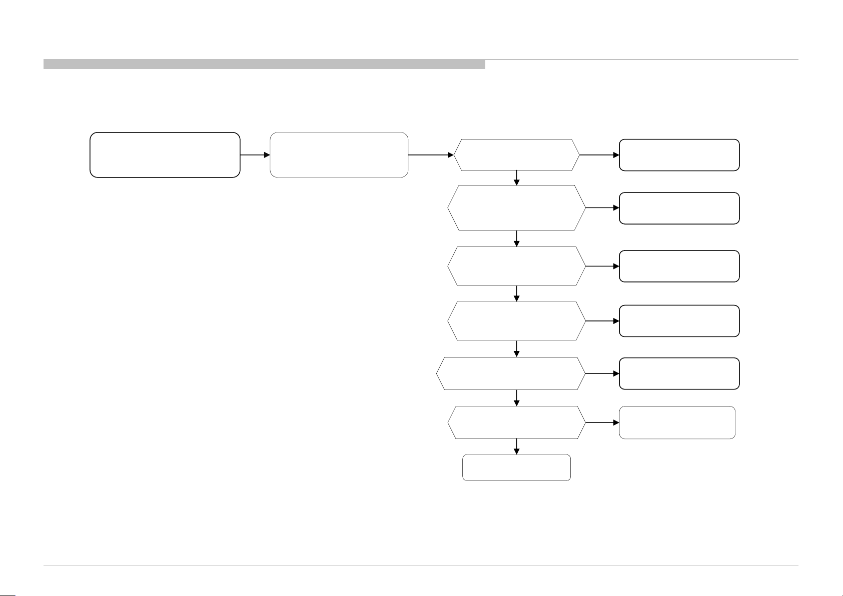
Page 52

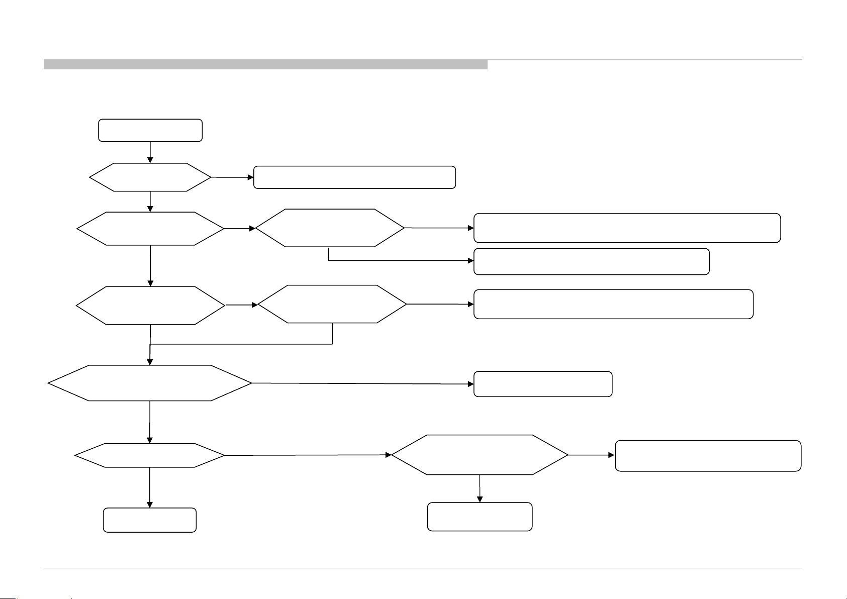
3-2-2. NO POWER-U-Com Failure (1/2)
START
TROUBLE SHOOTING
Check C9117 Voltage.
Is the voltage >3.0V?
Yes
Check R9186 Voltage.
Is the voltage >3.0V?
Yes
Check OPWRSB
R9179 Voltage.
Is the voltage 0V?
Yes
Check POWER_ON
P-on ucom #pin19
Is the voltage >3.0V?
yes
No
No
No
No
Check +3.3V_STBY
R9144, CN9000 #26pin
Check DC_OFF_DET
IC9018
Check STBY_MHL
R9176 Voltage.
Is the voltage >3.0V?
Yes
No problem
TV set stays in
STBY MHL charge mode.
Try AC Off and On after few minutes.
If #pin19 keep Low, change IC9017.
If #pin19 goes High few seconds and downs to Low,
Check G board and harness.
No
SOC
Muffin
problem
Check MAIN_VCC
R9175 Voltage.
Is the voltage >1.6V?
Yes
Check P_ON_VBUS
P-on ucom #pin11
is >3.0V?
Yes
Check P_ON_#1
P-on ucom #pin13
is >3.0V?
Yes
Check PGOOD_1
R9173 Voltage.
Is the voltage >3.0V?
A
No
No
No
No
G-Board
Change IC9017
Change IC9017
No POWER - DDCON/LDO
Check 1.0V DDCON (IC9008)
Check P_ON_LNB
P-on ucom #pin15
Is the voltage >3.0V?
KD-65X8000C(CH)
No
Change IC9017
Yes
52
Page 53

3-2-2. NO POWER-U-Com Failure (2/2)
A
Yes
TROUBLE SHOOTING
Check P_ON_#2
P-on ucom #pin14
Is the voltage >3.0V?
Yes
Check ORESETB
P-on ucom #pin12
Is the voltage >3.0V?
Yes
Check X_SYSTEM_RST
P-on ucom #pin16
Is the voltage >3.0V?
Yes
If PANEL_PWER_ON (R9172) is 0V
Check XRST
P-on ucom #pin17
Is the voltage >3.0V?
Yes
If BL_MUTE (R9174) is 0V
Check BL_ON
P-on ucom #pin18
Is the voltage >3.0V?
Yes
No
No
No
No
No
Change IC9017
Change IC9017
Change IC9017
Change IC9017
Change IC9017
Ucom IC9017 is working OK
KD-65X8000C(CH)
END
53
Page 54

TROUBLE SHOOTING
3-2-3. NO POWER: DC_OFF_DET check
START
Check Vdd
C9118
Is voltage >5V?
Yes
END
No
Change IC9018
3-2-4. NO POWER: DDCONs check
START
Check fuse
F9xxx
Is fuse OK?
Yes
Check Vcc voltage
C9xxx
Is voltage >12.0V?
Yes
Check Enable pin
voltage
Is voltage >2.5V?
Yes
Change DDCON IC
No
No
No
Check POWER_ON P-on ucom #pin19
(Refer to No Power U-Com Failure)
No Power U-Com Failure
Change Fuse
KD-65X8000C(CH)
54
Page 55

3-2-5. NO POWER: DDCON check
START
TROUBLE SHOOTING
Check IC9403 Vcc voltage
C9428
Is voltage >12V?
Yes
Check Vcc voltage
C9061
Is voltage >4V?
Yes
Check Enable
IC9010 #pin1
Is voltage >2.5V?
Yes
Change DDCON
IC9009
No
No
No
Check Vcc voltage
C9061
Is voltage >3V?
Yes
Check
D9001
Is diode ?
Yes
Change IC9010
No
No
Check
D9000
Is diode ?
No
Yes
Change D9001
Check +5V_MAIN DDCON (IC9001)
Change D9000
Check G board and harness
KD-65X8000C(CH)
55
Page 56

3-2-6. NO POWER: LDOs check check
START
Yes
TROUBLE SHOOTING
Check Vcc voltage
C9xxx
Is voltage >3V?
Yes
Check Enable pin
voltage
Is voltage >3V?
Yes
Change LDO IC
No
No
Check +3.3V_MAIN DDCON (IC9003)
1.2 No Power U-Com Failure
KD-65X8000C(CH)
56
Page 57

3-3. STANDBY LED BLINKING
3-3-1. 2 Times Blinking (Main power Error)
TROUBLE SHOOTING
3-3-2. 3 Times Blinking (DC Alert)
2-time blinking
Check +12V_REG
at pin 13/15/17 of CN9000
on B* Board,
Voltage > 13.2V ?
No
B* Board
Yes
G* Board
BMFL/BMFW board
3-time blinking
Check +5.0V_MAIN
at pin1 in IC8001, 4.959V
<Voltage<5.285V?
OK
AUDIO
Go to Audio check point
NG
DC_ALERT
IC9014,etc
(B* Board)
KD-65X8000C(CH)
57
Page 58

3-3-3. 3 Times Blinking (Audio Error)
TROUBLE SHOOTING
LED 3x blinking
Audio Error ?
Yes
Go to page
Power Off Checking*1
Go to page
Power off Checking*2
No
See other flow
Segment “XS”?
No
Yes
Replace B-K Harness
OK ?
No
Replace K-PWB
OK ?
No
Replace B-PWB
OK ?
Yes
Yes
Yes
B-K harness NG
K-PWB NG
B-PWB NG
KD-65X8000C(CH)
58
Page 59

1) Power Off Checking*1
Power Off Check*1
Segment “XS”?
Yes
No
(1) B-PWB
PVDD-GND short ?
(See Note 1)
Yes
(1) PVDD-GND short check
Measure impedance between PVDD and GND at C7706,
C7707.
If impedance is <100Ω → NG
(2) LDO out short check
Measure impedance between +3.3V and GND at C9130.
If impedance is <100Ω → NG
(3) Fuse open check
Measure impedance of fuse F7700, F7702 5A (12.5V)
If fuse open → NG
(1) K-PWB
PVDD-GND short ?
(See Note 2)
Yes
TROUBLE SHOOTING
Note 2: Note 1:
(1) PVDD-GND short check
Measure impedance between PVDD and GND at C7722, C7762, C7782,
C7834.
If impedance is <100Ω → NG
(2) LDO out short check
Measure impedance between +3.3V and GND at
C7909.
If impedance is <100Ω → NG
(3) Fuse open check
Measure impedance of fuse
F7702, F7704, F7705, F7701 5A (12.5V)
F7700 3.15A (DDC5V)
If fuse open → NG
Power Off Check*3
(2) B-PWB
LDO out short ?
(See Note 1)
(3) B-PWB
Fuse broken ?
(See Note 1)
KD-65X8000C(CH)
No
No
No
Yes
Yes
Replace B-PWB
No
(2) K-PWB
LDO out short ?
(See Note 2)
No
(3) K-PWB
Fuse broken ?
(See Note 2)
No
Yes
Yes
Replace K-PWB
Measure the Speaker
impedance by multi-meter
Less than 3Ω ?
No
Confirm the speaker
harness
Cut or shorted
to the chassis ?
No
Return to LED 3x blinking
or Power Off Checking*3
Yes
Replace Speaker
Replace Speaker Harness
Yes
59
Page 60

2) Power Off Checking*2
Power Off Check*2
Segment “XS”?
No
(4) 12.5V check
12.5V is supplied to
B-PWB for a moment
before LED 3x blinking ?
No
Yes
Yes
(5) 12.5V check
12.5V is supplied to
K-PWB for a moment
before LED 3x blinking ?
No
Yes
TROUBLE SHOOTING
(4) 12.5V check BMFL / BMFW
Measure voltage between PVDD and GND at
capacitor C7706 or C7707.(See 3.3)
Voltage rise more than 0V for a moment at
power on
→ Yes
(5) 12.5V check KS-PWB (XS)
Measure voltage between PVDD and GND at
capacitor C7722, C7762, C7782 or C7834. (See
3.3)
Voltage rise more than 0V for a moment at
power on
→ Yes
Replace B-K Harness
KD-65X8000C(CH)
OK ?
No
Replace G-PWB
OK ?
No
Return to
LED 3x blinking
Yes
Yes
Finish
Replace G-K Harness
OK ?
No
Replace G-PWB
OK ?
No
Return to
LED 3x blinking
Yes
Yes
Finish
60
Page 61
3) Power Off Checking*3
No Sound
Without LED 3x
AV receiver is connected
to HDMI in ?
Yes
Select [External Inputs]→
[BRAVIA Sync Settings]→
[BRAVIA Sync Control]→[off]
No sound only
Analog RF and Digital RF ?
No
TROUBLE SHOOTING
Yes
Go to
No Sound Tuner
No
[Speakers] setting is
[Audio System] ?
No
Headphone is connected to
HP/Audio Out terminal ?
No
[Sound]→
[Headphone Speaker Link]
setting is [On] ?
No
Go to
Power Off Checking*1
Yes
Yes
Yes
Change the setting to
[TV Speakers]
Disconnect the Headphone
Change [Sound]→
[Headphone Speaker Link]
Yes
to [Off], OK ?
No
Replace B-PWB
HP/Audio out terminal or Headphone detect
GPIO may be broken
No sound only HDMI ?
No
Go to
No Sound Audio
Yes
Go to
No Sound HDMI
KD-65X8000C(CH)
61
Page 62

3-3-4. 5 Times Blinking (Panel Communication Error)
5-times blinking
TROUBLE SHOOTING
Check
“+12.5V_TCON” at
CN9000
on the B-Board
OK
Replace the Harness
Between G-Board
and B-Board
NG
Replace
the V-By-One FFC
NG
NG
Replace G-Board
Symptom
improve
Symptom
improve
OK
NG
Harness is
suspicious
V-By-One FFC
is suspicious
G-Board is
suspicious
Change
B-Board
Symptom
improvement
B-Board is
suspicious
NG
Panel (T-con)
Panel (T-Con) is
suspicious
Change
Symptom
improvement
KD-65X8000C(CH)
62
Page 63

3-3-5. 6 Times Blinking (Backlight Error)
6-times blinking
TROUBLE SHOOTING
Check a voltage of
BL_ERR_DET.
Check point is
JL9007
or
23pin of CN9000
on B*Board
Voltage < 1.8 V
Voltage ≥ 1.9 V
Check
harness/connection
G*board to B*Board
or
LD board to B*Board
Harness /
Connection OK
Harness /
Connection
broken
Change LD board or G* board.
No improvement
No Improvement
Change
harness
No improvement
LED driver or G* board
Change
Panel
Change
B* board
Symptom
Improvement
Symptom
Improvement
Symptom
Improvement
Symptom
Improvement
Harness
LD board/G board
Panel
B* Board
KD-65X8000C(CH)
63
Page 64

3-3-6. 7 Times Blinking (Temperature Error)
7-time blinking
Setting
circumstance is OK?
Temperature,
No
Set to another
location, etc.
Ventilation, etc.
Yes
TROUBLE SHOOTING
Change B* Board,
and Aging a few
hours
Symptom
improvement
B* Board NG
NG
Panel
Check I2C_C bus
communication OK?
(check the next page)
No
I2C_C bus dumping or
Muffin check
Yes
Temp sensor
IC1400
KD-65X8000C(CH)
64
Page 65

3-4. NO SOUND
3-4-1. No Sound Audio
TROUBLE SHOOTING
3-4-2. No Sound : TUNER
No Sound
Audio
Segment “XS”?
No
Yes
Replace B-K Harness
OK ?
No
Replace K-PWB
OK ?
No
Yes
Yes
No Sound with normal picture
Only RF tuner input?
YES
Check IC1000 (SOC)
NO
Please refer Audio
troubleshooting
KD-65X8000C(CH)
Replace B-PWB
OK ?
Finish
Yes
65
Page 66

3-4-3. No Sound : MHL
No Sound
Check the picture
OK
TROUBLE SHOOTING
NG
Refer to MHL NO PICTURE
Check Sound by other TV set
which is same model
NG
Check Source equipment
by Reference TV set
(For example, Samsung TV(UN46ES7000),
Toshiba TV(42WL863), RB1 or RB2)
NG
Check the settings of
Source equipment
OK
Refer to No Sound Audio
OK
Change B-Board.
KD-65X8000C(CH)
66
Page 67
3-4-4. No Sound : HDMI1/2/3/4
No Sound
TROUBLE SHOOTING
Check the picture
OK
Check the mode
of Source equipment
HDMI
Does this model have
Analog Audio In
(Stereo minijack)?
NO
Check Sound by other TV set
which is same model
NG
Is Distributor used ?
YES
NG
DVI
YES
Refer to HDMI (1/2/3/4) NO PICTURE
Does this model have
“HDMI/DVI Audio Source”
Auto or HDMI Audio
OK
NO
Analog Audio In
(Stereo minijack)?
setting is?
YES
No
Analog Audio In
Check Source equipment
by Reference TV set
(For example, RB2, RB1)
Connect Stereo minijack cable between Source and the TV, and
Change “HDMI/DVI Audio Source” to Auto or Analog Audio In.
Change the mode of Source equipment to HDMI
Change “HDMI/DVI Audio Source” to Auto or HDMI Audio In
Refer to No Sound Audio
OK
Change B-Board.
NG
KD-65X8000C(CH)
Connect Source
equipment directly
Check the settings of
Source equipment
67
Page 68
3-5. NO PICUTURE
TROUBLE SHOOTING
No Picture
Got Any Normal
Display?
Yes
Check Other
Portion:
Ext. Video Input -
HDMI - No Picture
Tuner - No Picture
Check Smart Core
No
No Picture
Behavior
(5x Blinking)
Yes
5x Blinking
BL_ON (L or H): IC9017 #18pin (for 4K BMFW/BMFL board)
BL_ON:H
No
Check
BL_ON
on the main board
BL_ON:L
Backlight
Replace
the V by One FFC
Harness
Symptom
improvement
V by One FFC
Harness
NG
Replace
the main Board
Symptom
improvement
Main board NG
NG
LCD Panel
(T-CON)
KD-65X8000C(CH)
68
Page 69

3-5-1. No Picture CH/MX/PA/COL/LA (BMFL/BMFW)
No Picture Video
TROUBLE SHOOTING
Video 1
No Picture
Check if input OSD
is GREY OUT
OK if it is highlighted
OK
Check wave between
C7511 and IC1000
OK (Vpp: 1 V)
Muffin [IC1000]
Problem
NG
* Check J7505
Connection,
VIDEO2_DET
At R7562
** Detailed check all
parts at VIDEO2_DET
Signal Path [R7561]
NG (Vpp: 0 V)
J7505 Connector
Problem
NG (Vpp: 0 V)
OK (Vpp: 3.3 V)
NG (Vpp: 0 V)
OK (Vpp: 3.3 V)
** Detailed check all parts
at CVBS2P signal path
[D7514/R721/C7521/
J7505 Connectivity
Problem
R7519/C7534]
OK
NG
Parts Broken
Video 2
No Picture
Check if input OSD
is GREY OUT
OK if it is highlighted
OK
Check wave between
C7512 and IC1000
OK (Vpp: 1 V)
Muffin [IC1000]
Problem
NG
* Check J7504
** Detailed check all
parts at VIDEO_DET
Signal Path [R7535]
NG (Vpp: 0 V)
J7504 Connector
Connection,
VIDEO_DET
At R7539
OK (Vpp: 3.3 V)
OK (Vpp: 3.3 V)
Problem
NG (Vpp: 0 V)
NG (Vpp: 0 V)
J7504 Connectivity
** Detailed check all parts
at CVBS3P signal path
[D7530/R7524/R7525]
Problem
NG
OK
Parts Broken
[All voltage measurement using Oscilloscope]
KD-65X8000C(CH)
* OK Condition : No solder splash can be seen
NG Condition : Solder splash can be seen
** OK Condition : No part short-circuited
NG Condition : Part short-circuited
69
Page 70

3-5-2. No Picture : @ Tuner
RF input no picture / noisy picture
Check RF source cable
and antenna, OK?
Check Tuner power line:
3.3V at JL6005 = 3.3V?
1.8V at JL6006 = 1.8V?
DEM_3.3V at JL6019 = 3.3V?
A_RESET value at JL6012 = 3.3V?
For JP_SK only – TU1.1 V (Refer notes)
All broadcasting channel
cannot be received?
OK
OK
NO
NG
YES
Change RF cable and antenna
NG
Please refer DDCON
troubleshooting
Check part mounting condition
for “I2C_A_SDA, I2C_A_SCL
or
I2C_D_SDA, I2C_D_SCL”
Refer Note I2C
OK
NG
TROUBLE SHOOTING
Notes:
I2C line for all tuners except Japan_SKP
- Parts for I2C_A_SDA line: R6001, C6004.
- Parts for I2C_A_SCL line: R6002, C6005.
I2C line for Japan_SKP
- Parts for I2C_D_SDA line: R6003,C6006
- Parts for I2C_D_SCL line: R6004,C6007
TU_1.1V line only in Japan_SKP Tuner
- Parts for TU_1.1V: FB6800
Change NG parts
connected to I2C bus
KD-65X8000C(CH)
Analog
Refer Analog Tuning
Digital
Terrestrial/Cable
For TW & NA-ATSC
(MX/UC) only
Refer Digital Tuning 1
Satellite
Check Tuner power line
12V at JL6027 = 12V?
OK
All tuners except
TW & NA-ATSC(MX/UC)
Refer Digital Tuning 2
NG
12V LNB Voltage
Checking
70
Page 71

3-5-3. No Picture : HDMI1
No Picture
TROUBLE SHOOTING
Check other
HDMI input
All Inputs are NG
Check Picture by other TV set
which is same model
Target board & other TV set
both NG
Is Distributor used ?
No
Check Source equipment
by Reference TV set
(For example, RB1)
Reference TV set
NG
Check the settings of
Source equipment
Other Input is OK
Other TV set
OK
Yes
Reference TV Set OK
Change B-Board.
Change B-Board.
Connect Source
equipment directly
Change B-Board.
If you can do
component repair
If you can do
component repair
Check the below point at
Only +5V line
is NG
Spec:4.7~5.3V
Replace
R5515
JC5227, JC5228, JC5235, JC5236
JC5241, JC5242, JC5243, JC5244
Connector side
・Check +5V line
・Check HPD line
・Check DDC lines
・Check TMDS lines
+5V line is OK
and HPD line
is NG
Spec:2.4~5.3
V
Replace IC5212
(HDMI EQ).
Replace
IC1000
All lines
are NG
Only DDC
lines
are NG
Replace IC5212
(HDMI EQ).
Replace
CN5202
Only TMDS
lines
are NG
Replace
JC5216, JC5217
RB5209, RB5210
NG
NG
KD-65X8000C(CH)
71
Page 72

3-5-4. No Picture : HDMI2
No Picture
TROUBLE SHOOTING
Check other
HDMI input
All Inputs are
NG
Check Picture by other TV set
which is same model
Target board & other TV set
both NG
Is Distributor used ?
No
Check Source equipment
by Reference TV set
(For example, RB1)
Reference TV set
NG
Check the settings of
Source equipment
Other Input is OK
Other TV set
OK
Yes
Reference TV Set OK
Change B-Board.
Change B-Board.
Connect Source
equipment directly
Change B-Board.
If you can do
component repair
If you can do
component repair
Check the below point at
Connector side
・Check +5V line
・Check HPD line
・Check DDC lines
・Check TMDS lines
Only +5V line
is NG
Spec:4.7~5.3V
Replace
R5517, R5518
Replace IC5212
JC5227, JC5228, JC5235, JC5236
JC5241, JC5242, JC5243, JC5244
+5V line is OK
and HPD line
is NG
Spec:2.4~5.3
V
(HDMI EQ).
Replace
IC1000
All lines
are NG
Only DDC
lines
are NG
Replace IC5212
(HDMI EQ).
Replace
CN5202
Only TMDS lines
are NG
Replace
JC5208, JC5209
RB5211, RB5212
NG
NG
KD-65X8000C(CH)
72
Page 73

3-5-5. No Picture : HDMI3
No Picture
TROUBLE SHOOTING
Check other
HDMI input
All Inputs are
NG
Check Picture by other TV set
which is same model
Target board & other TV set
both NG
Is Distributor used ?
No
Check Source equipment
by Reference TV set
(For example, RB1)
Reference TV
set
NG
Check the settings of
Source equipment
Other Input is OK
Other TV
set OK
Yes
Reference TV Set OK
Change B-Board.
Change B-Board.
Connect Source
equipment directly
Change B-Board.
If you can do
component repair
If you can do
component repair
Check the below point at
Connector side
・Check +5V line
・Check HPD line
・Check DDC lines
・Check TMDS lines
Only +5V line
is NG
Spec:4.7~5.3V
Replace
R5428
Replace IC5212
JC5227, JC5228, JC5235, JC5236
JC5241, JC5242, JC5243, JC5244
+5V line is OK
and HPD line
is NG
Spec:2.4~5.3
V
(HDMI EQ).
Replace
IC1000
Only DDC lines
are NG
Replace IC5212
(HDMI EQ).
All lines
are NG
Replace
CN5203
Only TMDS lines
are NG
Replace
JC5237, JC5238
RB5213, RB5214
NG
NG
KD-65X8000C(CH)
73
Page 74

3-5-6. No Picture : HDMI4
No Picture
TROUBLE SHOOTING
Check other
HDMI input
All Inputs are NG
Check Picture by other TV set
which is same model
Target board & other TV set
both NG
Is Distributor used ?
No
Check Source equipment
by Reference TV set
(For example, RB1)
Reference TV
set
NG
Check the settings of
Source equipment
Other Input is OK
Other TV
set OK
Yes
Reference TV Set OK
Change B-Board.
Change B-Board.
Connect Source
equipment directly
Change B-Board.
If you can do
component repair
If you can do
component repair
Check the below point at
Only +5V line
is NG
Spec:4.7~5.3V
Replace
R5467
JC5227, JC5228, JC5235, JC5236
JC5241, JC5242, JC5243, JC5244
Connector side
・Check +5V line
・Check HPD line
・Check DDC lines
・Check TMDS lines
+5V line is OK
and HPD line
is NG
Spec:2.4~5.3
V
Replace IC5212
(HDMI EQ).
Replace
IC1000
Only DDC lines
are NG
Replace IC5212
(HDMI EQ).
All lines
are NG
Replace
CN5208
Only TMDS lines
are NG
Replace
JC5239, JC5240
RB5215, RB5216
NG
NG
KD-65X8000C(CH)
74
Page 75

3-5-7. FOR ANALOG TUNING: @ All destination except JP
Analog Tuning
For Other destination
For LA-ISDB(BR/AR), LA-T2(COL) and TW only
Confirm ANT or Cable connection A
OK
NG
TROUBLE SHOOTING
Notes:
- Parts for IFOUT_N line: R6007, FB6002, C6008, R6327,
C6301, R6301.
- Parts for IFOUT_P line: R6008, FB6003, C6009, R6326,
C6300, R6300.
- Parts for IFAGC line: R6072, R6009, R6010, R6069, C6302,
R6303.
A
: Insert correct signal in correct terminal.
KD-65X8000C(CH)
Check part mounting condition for
analog control line
“IFOUT_N, IFOUT_P, IFAGC”
OK
Check IC1000(SOC)
NG
Change NG parts
75
Page 76

3-5-8. FOR DIGITAL TUNING 2: @ AEP_W, JP_SKP, PA_T2, CH/HK, LA-ISDB(BR/AR) and LA-T2(COL)
TROUBLE SHOOTING
For LA-ISDB(BR) and
LA-T2(COL) only
NG
Confirm ANT or Cable connection Confirm ANT or Satellite connection
OK
Digital cable/ Terrestrial
Cable
Refer to Digital Tuning 1
“TU1_TS_DATA0, TU1_TS_CLK, TU1_TS_VALID, TU1_TS_SYNC”
Terrestrial
Check part mounting condition for digital data line
Digital Tuning 2
For PA_T2 and
A A A
Sound is normal?
No sound
Change NG parts
CH/HK only
On Service
mode display
TS_LOCK ?
UEC ?
CASE A
NG
OK
CASE B
For AEP-W
OK
OK
All except SKP_Opticast
Check IC1000 (SoC)
Change Tuner module
(Refer to Note tuner )
Check IC1000 (SoC)
NG
For JP_SKP
Confirm ANT or Satellite connection
OK
BS/CS or SKP_Opticast/
SKP_Premium or terrestrial
SKP_Opticast
Refer to Digital Tuning 1
Notes:
- Parts for TU1_TS_DATA0 line: R6015,
R6321.
- Parts for TU1_TS_CLK line: R6016, R6322.
- Parts for TU1_TS_VALID line: R6017, R6323.
- Parts for TU1_TS_SYNC line: R6018, R6324.
- CASE A : TS _LOCK = LOCK and UEC
constant
- CASE B : TS _LOCK = UNLOCK or UEC is
increasing
Note Tuner –
(IC reference -- destination)
TU6001 - PA-T2
TU6001 - LA-T2/LA-ISDB
TU6001 - CH, HK
TU6003 - AEP_W
TU6802 - JP_SKP
: Insert correct signal in correct terminal.
A
NG
KD-65X8000C(CH)
76
Page 77

3-6. SIDE BUTTONS MALFUNCTION
TROUBLE SHOOTING
Side Key button
malfunction
Change Switch Unit
OK
NG
Harness on Switch Unit
and B* Board properly connected
NG
Change
Switch unit-B* board Harness
NG
Power Key (B*Board)
Check parts value :
0 ohm < R1089 < 2 ohm
4.4k ohm < R1432 < 5k ohm
OK
Power Key Muffin Pin (B*Board)
Check voltage(Power ON condition) :
3.13V < Voltage < 3.47V
OK
OK
NG
OK
Switch unit issue
Harness
connection
issue
Harness issue
Parts Broken issue
Muffin IC1000
problem
NG
OK
NG
Key AD(B*Board)
Check parts value :
0 ohm < R1091 < 2 ohm
0 ohm < R1042 < 2 ohm
OK
Key AD muffin pin (B*Board)
Check voltage (Power ON condition):
1.62V < voltage < 1.84V
KD-65X8000C(CH)
NG
NG
Change B*Board
77
Page 78

3-7. IR REMOTE COMMANDER MALFUNCTION
TROUBLE SHOOTING
IR do not response to
Remote Commander
Center white LED
lit up when remote
control is pressed
NG
Harness on H-board
and B* Board
properly connected
NG
Change
H-B* board Harness
NG
Change Smart Core
NG
B*Board
Check parts value :
R1080 = zero ohm
OK
OK OK
OK
Check whether center
white LED blink ,when using
commander near the sensor
windows
Harness
connection
issue
OK
H-B* board harness
issue
OK
Smart core issue
NG
Parts Broken issue
Remote control battery
could be weak.
Change battery.
KD-65X8000C(CH)
SIRCS (IC1000 Pin Y35 , B*Board)
Check voltage (Power ON condition):
3.287V < Voltage < 3.55V?
NG
Change B*Board
OK
Muffin IC1000
problem
78
Page 79
3-8. LIGHT SENSOR ERROR
TROUBLE SHOOTING
Backlight doesn’t change
when ambient lighting
level changed
Check UI setting for light
Sensor. Make sure it is “on”
Change the UI setting
to “ON”
NG
Harness on H-board and
B* Board properly connected
NG
Change
H-B* board Harness
NG
Change Smart Core
NG
B*Board
Check LIGTH_SENSOR signal path :
R1079 = zero ohm
OK
LIGTH_SENSOR (Muffin Pin L35)
Check voltage variation from
room light to dark condition
NG
OK
OK
OK
OK
NG
OK
User did not activate light
sensor function
Harness connection
issue
H-B* board harness
issue
Smart Core issue
Part broken issue
Muffin IC1000 problem
KD-65X8000C(CH)
Change B*Board
79
Page 80

3-9. NETWORK MALFUNCTION
1) Ethernet (Wired)
[Network Set-up]
>[Wired Set-up]
on the TV
TROUBLE SHOOTING
OK
Connection Results
Cable Connection
Failed
OK
Check cable B board
NG
Ethernet Cable
Connection Results
Local Access
Failed
Wired Set-up
IP address setting
Manual
Check IP address
&
Local router setting
OK
Auto
Check
Local router
DHCP server
Connection Results
Internet Access
Failed
Proxy setting
OK
B board
KD-65X8000C(CH)
80
Page 81

2) Internal Wireless Network malfunction
Wireless Network
on the TV
TROUBLE SHOOTING
Error Message appear
when the Wireless
Network is selected?
Yes
From previous page
Check harness
connection is OK
between WiFi and Bxx
OK
Change
Wi-Fi module
OK If Wi-Fi malfunction happens,
Wi-Fi module
NG
No
NG
NG
Is the radio field
Strength too weak
or even No signal?
Yes
Change WiFi module
OK
WiFi module
Connect properly
OK
Change harness
between Bxx board
and WiFi
OK
Main Harness
No
NG
Loose harness
NG
Change Bxx board
Bxx Board
Access Point
• Wi-Fi module
• Harness between WiFi
and Bxx
• Bxx board
are suspected.
KD-65X8000C(CH)
81
Page 82

3) Bluetooth malfunction
Touch pad Remote doesn’t work
3D-glasses (Active) doesn’t work
Bluetooth Speaker/Headphone/Headset doesn’t work
Home > Settings >
Bluetooth Settings
NG
else
Or
Or
OK
Can read
Near discoverable
Bluetooth Device
Check BT antenna
Connection is OK
OK
NG
TROUBLE SHOOTING
Please refer
Touch pad Remote manual
3D-glasses (Active) manual
Or
Bluetooth Speaker/Headphone/Headset operation manual
Check harness
connection is OK
between BT and Bxx
KD-65X8000C(CH)
OK
Change BT module
OK
BT module
NG
NG
NG
NG
Connect properly
Change harness
Between Bxx board
and BT
Main Harness
Connect properly
OK
OK
NG
OK
Loose harness
Change Bxx board
Loose BT antenna
connection
82
Page 83

SEC 4. DIAGRAMS
4-1. BLOCK DIAGRAM
Tu Pack
Ether
HDMI1
HDMI2
/MHL
HDMI3
HDMI4
Tuner
CVBS Jack
I2C
(Audio)
TEMP
Sensor
HDMI EQ
Composite2/Component
DVI/HDMI3
Audio in
USB3.0 USB2.0
USB2.0
SmarCore
WIFI/BT
Main SoC
LOG
eMMC
DDR3
2Gb
I2C(Backlight,Panel)
UART(4KBE
Communication)
AudioAMP
HP/Line out
LOG
ECS
Vx1 x8
Vx1 x4
Key-pad
Sub SoC
Opt.Out
I2C(panel)
Vx1 x16
LD
I2C(Backlight)
I2C
(Audio)
AudioAMP
AudioAMP
AudioAMP
AudioAMP
AudioAMP
AudioAMP
LD
SoC
KD-65X8000C(CH)
83
Page 84

DIAGRAMS
(Only Interface between board and board)
CN360 1 To BMFW
CN203 GND 1 51 GND
1-798-511-11(ALPS)/ HUS_GND 1 19 VBTX7P 2 50 RxP7
1-798-510-12(NOBLE) HUS_KEY_AD 2 18 VBTX7N 3 49 RxN7
HUS_POWER_KEY 3 20 GN D 4 48 GND
1-821-143-11 1-821-117-11
VBTX6P 5 47 RxP6
JAM SYT10-3WL SYT10-03HG VBTX6N 6 46 RxN6
GND 7 45 GND
VBTX5P 8 44 RxP5
VBTX5N 9 43 RxN5
GND 10 42 GND
VBTX4P 11 41 RxP4
CN100 0 VBTX4N 12 40 RxN4
1 1 WIFI_GND GND 13 39 GND
2 2 X_WIFI_BT_RST VBTX3P 14 38 RxP3
3 3 X_WIFI_WAKEUP VBTX3N 15 37 RxN3
4 4 X_BT_WAKEUP GND 16 36 GND
5 5 WIFI_GND VBTX2P 17 35 RxP2
6 6 WIFI_STBY_3.3V VBTX2N 18 34 RxN2
USB 7 7 WIFI_STBY_3.3V GND 19 33 GND
USB 8 8 WIFI_STBY_3.3V VBTX1P 20 32 RxP1
9 9 WIFI_GND VBTX1N 21 31 RxN1
10 10 WIFI_GND GND 22 30 GND
USB 12 11
WIFI_GND
VBTX0P 23 29 RxP0
11 12 BT_3D_LR VBTX0N 24 28 RxN0
13 13 WIFI_GND GND 25 27 GND
USB 14 14 WIFI_USB_M VBTXLOCKN0 26 26 LOCKN
NC 15 NC VBTXHTPDN0 27 25 HTPDN
USB 15 16 WIFI_USB_P GND 28 24 GND
NC 17 NC GND 29 23 AGP/NSB (High/Open:AGP, Low: N SB)
2 18 HUS_KEY_AD NC 30 22 NC
1 19 CAM_GND BITSEL 31 21 NC (BITSEL(High/Open :10Bit; L:8Bit))
CN001 3 20 HUS_POWER_KEY /WP/(BINT) 32 20 nWP (High:Write; L/Open: Protect)
STBY3.3V 1 25 11 21 SC_OPT_SENSE SCL 33 19 SCL
5V_MAIN 2 22 2 22 5V_MAIN SDA 34 18 SDA
GND 3 27 12 23 SC_SIRCS 3D_EN/ (MUTE) 35 17 PCID _EN (High: Enable, Low/Open: Disable)
LED_AMBER 4 24 4 24 SC_ LED_AMBER 3D_SYNC_IN 36 16 NC
LED_PWM_W 5 26 1 25 SC_STBY_3.3V 3D_SYNC_OUT 37 15 NC
LEY_PWM_R 6 32 5 26 SC_LED_PWM_W GND 38 14 GND
LED_PWM_B 7 30 3 27 SC_GND PANEL_DET 39 13 GND
LED_PWM_G 8 28 8 28 SC_LED_PWM_G GND 40 12 GND
GND 9 29 9 29 SC_GND NC/GND 41 11 GND
MAIN_3.3V 10 31 7 30 SC_LED_PWM_B NC 42 10 GND
OPT_SENSE 11 21 10 31 SC_MAIN_3.3V NC 43 9 NC
SIRCS 12 23 6 32 SC_LED_PWM_R NC(PANEL_RESETX)/12V 44 8 NC
1-821-139-11 1-821-126-11 NC 33
SC_GND
NC(PANEL_READY)/12V 45 7 NC
JAM SY T10- 12W S SYT10-12HG NC 34
NC
NC/12V 46 6 NC
NC 35
MIC_GND
NC(PANEL_PWR)/12V 47 5 NC
NC 36
MIC_RESET
NC(PANEL_ON)/12V 48 4 NC
NC 37
I2S_BCK(SIELDED)
NC(ABL_HOT2)/12V 49 3 NC
NC 38
I2S_LRCLK(SIELDED)
NC(ABL_HOT1)/12V 50 2 NC
NC 39
HUS_GND
NC(ABL_HOT0)/12V 51 1 NC
USB Cable(UL2725) NC 40
CAM_POP
1-819-812-11
GND 1 1 1-819-538-11 1-818-692-23 FFC Dire ct Conn ect or :I PEX JAE/FI -RE5 1S-H F
RST_L 2 2 SHLD P-40V-S-1 (B) JST SM4 0B-S HLDS -GAN F-1- TF(L F)(S N)
WOW_L 3 3
WOBT_L 4 4 CN36 00 To BMFL
GND 5 5 NC/HTPDN1/ELTIMO3/POWER_ON 1 41 NC
VCC 6 6 CN800 4 NC/LOCKN1/ABL_PHT/READY 2 40 NC
VCC 7 7 3 BLK#2 8 1
CAMERA_5V
NC/SDA/PANEL_ERROR/PANEL ON 3 39 NC
VCC 8 8 3 RED#28 2
CAMERA_USB_M
NC/SCL/PANEL ERROR 4 38 NC
GND 9 9 3
CAMERA_USB_P
SPI_CS 5 37 NC
GND 10 10 4
ID (GND/CLK/CAM_POP) : Conne ct GND via R=0 Ohm
SPI_CK 6 36 NC
VSYNC 11 12 5
GND_S
NC/RESETX 7 35 NC
GND 12 11 3 Shield 1-822-265-21 NC 8 34 NC
GND 13 13 ACON Mini -USB NC 9 33 NC
DM 14 14 3 WHT#2 8 NC 10 32 NC
DP 15 16 3 GRN#28 NC 11 31 NC
1-819-332-11 1-819-502-11 VCA/(SPI_SEL0) 12 30 NC
JST SM 15B -GHS -TB (LF)( SN)
GHR-15V-S CN900 0 BUS_SW 13 29 NC
NC 30
DIGITAL_STBY
SPI_DI/(WDT) 14 28 NC
2 29
DC_DIMMER
SPI_DO 15 27 HTPDN (LGD Use Only)
3 28
BL_ON/ICS PCLK
SPI_ENB 16 26 LOCKN (LGD Use Only)
4 27
PWM_DIMMER
GND 17 25 GND
5 26
STBY_3.3V
VBTX15P 18 24 RxP15
6 25
BLINKING
VBTX15N 19 23 RxN15
NC 24
AC_OFF_DET
GND 20 22 GND
8 23 BL_ERR VBTX1 4P 21 21 RxP14
9 22
POWER_ON/ICSP DAT VBTX14N 22 20 RxN14
10 21 GND GND 23 19 GND
11 20 GND VBTX13P 24 18 RxP13 J110
12 19
GND
VBTX13N 25 17 RxN13
GND Ground
1
21 AWG#22
13 18
REG12V_Audio
GND 26 16 GND
GND Ground
2
23 AWG#22
14 17
REG12V
VBTX12P 27 15 RxP12
PWR Power V12 IN
3
NC
15 16
REG12V_Audio
VBTX12N 28 14 RxN12
PWR Power V12 IN
4
25 AWG#22
16 15
REG12V
GND 29 13 GND
PWR Power V12 IN
5
27 AWG#22
NC 14 REG12V_Audio VBTX11P 30 12 RxP11 1-822-322-11 1-820-264-11
18 13 REG12V VBTX11N 31 11 RxN11 JST SM05B-PASS-TBT(LF)(SN) PAP-05V-S
NC 12 GND GND 32 10 GND
20 11 GND VBTX10P 33 9 RxP10
NC 10
TCON_GND/VPP_ PIC VBTX10N 34 8 RxN10
22 9 GND GND 35 7 GND
NC 8 TCON_GND VBTX9P 36 6 RxP9
24 7 TCON_ON VBTX9N 37 5 RxN9
NC 6 TCON_VCC12V GND 38 4 GND
26 5 TCON_VCC12V VBTX8P 39 3 RxP8
NC 4 TCON_VCC12V VBTX8N 40 2 RxN8
NC 3 TCON_VCC12V GND 41 1 GND
NC 2 GND 1-819-564-11
NC 1 GND FFC D irec t Co nne ctor :IP EX JAE/FI- RE41 S-HF
1-843-925-11 1-843-917-11
PBDP-30V-S JST S M30B -PB DSS- TF
CN830 1
TM_SCL 1
TM_SDA 2
GND 3
TM_SPI1_SCK 4
TM_SPI1_MOSI 5
TM_SPI1_nSS 6
GND 7
TM_EMIT 8
BL_TYPE 9
TM_SPI0_SCK 10
TM_SPI0_MOSI 11
TM_SPI0_nSS 12
GND 13
TM_SPI_SYNC 14
TM_MODE0 15
TM_MODE1 16
TM_RDY 17
TM_LOG_RX 18
TM_LOG_TX 19
SA_MODE 20
VLEDPWM1 21
VLEDPWM0 22
CN770 6 Reserve 23
1 GND_D BL_ON 24
2 +5.0V_AUDIO 0-336-971-01
3 GND_D FFC 2 4pin IRI SO
4 X_SYSTEM_RST
5 X_DAMP_MUTE
6 X_AMP_ERR_DET
7 X_DAMP_RESET
8 I2C_C_SCL
9 I2C_C_SDA
10 DC_ OFF_DET
SPEAKE R
L+ 1 4 11 D AUOA_DAT3
Front
L- 2 3 12 D AUOA_DAT2
Lch
JST SMP-02VF-N 13 DAUOA_DAT1
1-784-991-21 14
DAUOA_DAT015DAUOA_LRCK16GND_D
SPEAKE R
R+ 1 1 17
DAUOA_BCK
Front
R- 2 2 18
GND_D
Rch
JST SMP-02VF-N 19
DAUOA_MCK
1-784-991-21 20
GND_D
1-819-407-71
IMSA-9 637 S-4 0-Y8 01
CN6401
1-842-551-11
SJM20 -28WL B/JAM
DIGITAL_STBY
1
NC
DC_DIMMER
2
29
BL_ON
3
28
PWM_DIMMER
4
27
STBY_3.3V
5
26 #22
BLINKING
6
25
AC_OFF_DET
7
NC CN770 0
BL_ERR
8
23 #24 1 1 SP_MAIN_RP
POWER_ON
9
22 #24 2 2 SP_MAIN_RN
GND
10
21 #22 #24 2 3 SP_MAIN_LN
GND
11
20 #22 #24 1 4 SP_MAIN_LP
GND
12
19 #22 1-842-593-11 1-842-566-12
REG12V
13
18 #22 PBVP0 4V-S SM 04B -PBV SS-T B(LF) (SN )(PS )
REG12V
14
17 #22
REG12V
15
16 #22
REG12V
16
15 #22
REG12V
17 NC
REG12V
18
13 #22
GND
19
NC
GND
20
11 #22
TCON_GND
21
1 #22
GND
22
9 #22
TCON_GND
23
2 #22
TCON_ON
24
7
TCON_VCC12V
25
4 #22
TCON_VCC12V
26
5
TCON_VCC12V
27
5 #22
TCON_VCC12V
28
NC
SJM20-28HG
1-842-598-11
CN6101
SFP79 -02WL B JAM
1-822-908-11
AC-N 1
AC-L 2
1-839-678-21
CN6801
1-822-360-11
53426-0510 Molex
NC1+OUT1
2
To LS
NC(No land)3NC(No land)4-OUT1
5
1-822-327-11
51103-0500
or Hi rose FH5 2-2 4S- 0.5S H
or Hi rose FH5 2-2 0S- 0.5S H
PANEL FFC
1-842-546-21
or Ya maich i 1 -84 3-1 07-X X
1-843-699-11
or Ya maich i 1 -84 3-7 08-X X
Main Harness
BAX_F Board
G-B Harness
GB Harness
GN1 Smart Core
Wifi/BT
BMFW Board
HSC3-L
SM (FY14)
GL6 Board
BT
Antena
51pin FFC
VbyOne-FFC
41pin FFC
VbyOne-FFC
AC pigtail
T-con Boar d
(LGD)
4-2. CONNECTOR DIAGRAM
KD-65X8000C(CH)
84
Page 85

4-3. PC BOARD DIAGRAM
BMFW (A SIDE)
DIAGRAMS
cam9
C7747
C7748
C7746
L7704
cam012
IRM001
KA001
C7715
C7716
C7714
C7873
C7874
C7731
TP3106
IC7700
R7758
C7711
cam058
C7708
C7863
C7704
R7748
R7749
R7760
R7761
cam103
cam095
KA003
cam100
cam101
C1441
cam102
IC1400
cam178
cam085
cam083
R1136
R1137
R1138
R1139
R1140
CN7703
R1141
cam017
cam3
TP3101
DM001
cam005
cam15
FB6001
C6002
C6001
R6063
R6062
R6061
C6024
C9077
L9005
C9071
C6013
C9066
C9063
C9111
C6014
C9079
C6015
C9083
FB6004
IC9005
cam12
R9052
R9049
C9057
C9054
R9057
R9047
C6003
C9052
R9056
cam086
cam4
cam010
cam001 cam002
KJ001 KJ002
C7749
CN7704
CN7700
L7705
L7706
C7717
L7700
R7766
R7750
R7751
R7752
R7967
F7700
C7706
R7728
cam003
CN1403
R1446
R1447
cam218
R1510
R1449
R1448
R1517
Q1402
C7764
C1463
cam043
Q1401
IC1408
R1518
Q1400
cam033
C7862
C7860
VR7701
R7964
R7966
C7858
R7961
C7861
C7859
VR7700
R7963
R7965
C7857
R7959
cam203
VD7532
VD7531
VD7530
C7542
C7541
C7540
D7535
VD7535
D7533
VD7534
D7534
C7544
C7548
C7549
R7577
R7574
R7576
CL7502
R7528
C7551
R7579
R7572
R7578
CL7505
C7547
C7550
CL7503
C7546
C6011
C6023
FB6003
C6009
R6008
FB6002
C6008
R6007
C6010
C6022
cam181
C1443
C1444
C1445
C1446
R1475
VD1402
TU6001
TU6000
cam004
CN7705
L7707
C7780
C7779
C7781
C7782
C7752
C7753
C7742
C7743
C7744
L7701
L7702
C7728
C7729
C7727
C7730
C7875
C7876
R7767
C7741
cam059
C2016
R2005
CN1400
VD7533
C7543
A6000
TU6802
TU6003
R1472
R1473
VD1401
C7707
IC7701
R7757
R7759
C7713
R7729
R7756
R7755
C7712
C7705
R7763
C7864
R7753
R7754
R7764
R7968
R2016
R2012
R2015
R2004
C2018
IC2002
R2003
C2015
C2021
R2013
C2019
cam046
IC2001
R2017
C2022
R2001
R2009
cam020
C2002
C1461
cam38
J7701
T8001
T8000
cam202
R8039
C8015
C8016
L8000
J7501
CN7501
J7504
VD7503
R7502
R7538
VD7502
VD7506
VD7501
CL7501
R7536
R7520
C7501
D7502
R7534
VD7505
D7505
D7536
D7501
D7508
R7509
R7503
D7511
R7505
C7508
R7517
C7510
C7545
C7506
R7506
C7503
L7500
R7510
D7510
R7518
C7509
R7533
CL7504
C1454
C1453
IC1402
R1481
J1401
cam006
CN7706
cam097
C7878
C7765
C7766
R7980
R7921
R7930
R7927
R7920
R7931
R7978
cam032
C7865
C7877
R7926
C7718
C7719
C7720
C7709
R7922
R1450
R7923
C7751
C7750
C7745
C7701
C7703
L7703
F7702
C7700
C7710
cam098
C2017
C2020
R2002
T8002
C8017
VD7504
VD7509
R7513
D7504
R7512
R7514
C7702
C2001
RB2003
RB2001
RB2002
RB2004
cam212
cam211
R1513
IC1407
IC1406
R1512
C2009
R2010
C2010
C2011
C2012
C2013
C2014
C1462
R1516
R1515
R1514
CN8003
RB8004
cam021
cam171
VD7507
R7524
D7500
D7532
D7506
C7514
R7531
C7519
D7530
R7523
R7529
C7517
D7531
R7532
R7552
VD7508
CM6004
C6016
R6015
R6070
CM6005
C6017
R6016
C6012
R6071
IC6000
CM6006
R6017
CM6012
R6072
R6018
CM6007
R6009
cam066
C6070
R6010
CM6008
R6020
C6025
R6069
CM6009
R6021
C6026
CM6010
R6022
R6033
CM6011
R6800
R6801
R6802
R6803
R6003
R6004
Q9018
C6007
C6006
F9009
C6004
C6005
R6001
R6005
R6006
R6002
R9190
R9189
C6021
C6020
FB6006
C9120
C6019
R9193
R9192
C6018
FB6005
F6000
Q9019
R6011
C6030
R6068
CM6003
TP3104
C6029
R6065
CM6002
R6014
C6028
R6064
CM6001
R6013
R6066
CM6000
R6012
C6027
R6067
R6019
C9053
R9058
R6036
R9050
R9048
Q6001
R9059
C9055
C9058
R9053
cam080
TP3103
C6800
FB6800
IC9006
C9084
R9079
C9078
C9072
F9010
C9067
C9080
R9078
C9112
R9080
C9064
L9006
C7521
D7512
R7558
R7521
R7592
VD7520
FB7502
D7514
D7513
COM751
R7562
cam8
R7561
cam007
J7505
cam002
cam005
CN1000
CL1008
CL1007
C1068
cam034
CL1006
C1067
CL1003
RB1000
VD1000
C1062
C1079
R1091
C1078
C1071
R1080
C1072
C1075
C1064
C1073
TP3111
R1109
R7932
R7933
R7934
R7935
R7936
R1000
R1004
VD7500
R7501
C7500
R7500
R7557
R7537
R7556
R7535
R7539
R1171
R7599
R7522
R1489
R1486
R1485
cam090
D1400
R1480
R1470
R1471
VD1400
C7560
R7593
C7562
C7559
C7561
VD7538
VD7539
D7537
D7538
cam288
C1061
R1062
R1088
R1075
R1079
VD1001
CL1004
C1070
R1085
R1082
R1107
C1065
CL1005
D1003
C1057
R1128
R1090
C1056
R1077
R1076
R1089
R1127
R1078
C1077
C1066
C1074
C1076
R1105
R1084
VD1002
R1106
C1083
R1081
R1087
R1086
R1083
C1055
R1108
R1126
R1129
D1002
D1001
R9154
R9156
C9117
cam217
R9155
R9179
R9157
R9210
R9177
R9158
R9176
R9161
R9159
R9173
R9175
R9162
R9172
CL5302
R9174
R9090
R1173
C8360
R8399
C1428
C1425
C8359
C8358
C1415
C1411
R1429
R1433
R1503
C1433
R8379
R8392
R8380
R1432
R1460
R1427
R1401
R1400
C1414
C1400
C1416
C1419
C1417
R1420
R1500
R1499
R1438
R1425
R1021
C1407
R1419
R1439
R1506
R1434
R1130
R8378
R1131
C1424
C1410
C1017
C1021
R1045
C1029
R1417
R1421
R1042
C1013
C1406
R1043
R1041
C1426
C1402
C1404
R1465
R1412
R1422
R1463
R1464
R1413
R1462
C1436
C1408
R1416
R1424
R1423
C1434
C1412
C1432
C1430
R1445
R1444
R1453
R1454
R1063
R1451
R1452
CL1002
R1125
C1043
R1030
R1113
C1009
C1012
R1031
R1054
R1114
R1053
C1032
C1028
C1019
R1036
R1035
R1026
R1112
COM100
R2014
C1006
R1022
C1011
R1119
R1024
R1121
C1015
R1025
ET032
C1409
C1413
R1501
R1402
C1431
R1415
C2023
R1440
R2006
C1422
R1414
R1441
R1459
C1423
C1420
C7783
R2011
C7786
R1430
C7785
C7784
C7787
R7721
C1401
R1442
R1443
C1405
R2007
R7715
R7720
R7719
C7788
R1437
R7717
R7723
R7713
R7714
R7718
R1435
R7716
R7712
R1509
R7722
R5476
C2003
C2008
C1403
R1436
C1440
C2007
R1469
R1468
R1458
C1439
R1457
C1427
R1428
R1507
RB2005
R1431
RB2006
R1508
C1418
R1426
R1502
C1429
R1050
C1042
R1001
R1162
R1049
C1040
R1005
R1046
C1033
R1099
R1418
C1421
R1511
R8043
R8057
R1172
F7701
CM7706
RB7713
C7808
CM7705
C7805
C7809
D1402
IC1404
IC1401
C8030
C8029
IC8006
R8031
R8033
C8039
cam036
C1038
C9808
CL7608
CL7606
CL7609
CL7602
C7601
R1161
C7600
CL7605
CL7604
CL7610
R1048
R9801
R7600
CL7607
CL7603
CL9802
FB7500
R7526
C7513
R1461
C7533
R7527
C7515
R7554
R1505
C1435
R7551
C7516
R7530
C7518
R7553
C7520
C7502
R7504
C7504
R7508
FB7501
C7505
R7507
C7532
C7507
R7511
R7525
C7512
R8044
C8005
C8022
C8021
Q8000
R8045
R7519
C7511
R6035
C8042
R8056
Q8001
R8017
R7515
R7516
R8042
R8018
CL8003
C8704
C8706
C8707
R8723
Q8002
C8702
R8058
D8001
R1047
C1036
cam052
C7739
C7736
CL7707
R7705
C7738
C7735
CM7702
R7802
C7732
FL7700
CL6301
CL6300
IC7702
R6302
R7747
R7746
R7709
R7710
R7708
R6300
R6301
R7707
C6301
C6300
cam071
CL7705
R7706
R6326
R6327
C7733
C7734
CM6301
CM6300
CL7751
R7852
R7846
CL7750
C7824
C7831
CL7752
C7823
R7571
R7573
CL7753
R7811
C7819
cam072
C7832
C7821
C7871
R7813
R7815
RB7712
IC7707
C7820
C7872
R7814
C7870
C7822
R7973
R5617
R5618
R7979
cam082
C7816
C7813
R5619
R7809
R7807
C7818
C7814
R7808
C7806
C7807
RB7711
RB7710
IC7703
RB7708
C7812
R7804
C7817
R7805
R7806
C7811
C7810
C7815
RB7709
C1455
cam022
R1478
C1449
R1487
RB1400
R1479
C1450
R5610
R5611
cam067
R8032
VD5600
D5600
C5606
IC8005
CL5248
Q5200
R5487
R5490
Q5209
R5207
C8028
D5200
C5295
cam068
R5489
D5201
JC8005
R5211
R5212
D5202
R5488
L8002
L8001
R5209
VD8012
VD8010
VD8011
VD8013
VD8002
VD8003
TP3107
R5210
C5222
Q5201
R5526
VD5211
CN8005
cam011
Q9027
Q9028
D9002
R9093
cam26
Q9029
R1073
C1082
R9166
R9194
R9168
R9180
R9178
R9163
R9164
R9165
IC9017
R9167
R9169
R9170
Q9022
Q9023
R9091
R9153
R9171
C1037
C1035
R1006
R1007
R1038
R1037
R1039
C1039
CL5220
R5486
R1142
C1041
R1122
R8701
R1111
C1026
R1040
C1001
R1015
R1016
C1030
R1019
C1034
R1017
R1102
C1004
R1018
C1000
R1118
C1002
R1020
C8357
R8377
C1024
C8356
R1117
R1034
C1020
R1116
R1033
C1016
R1032
R1115
cam049
JC8702
JC8704
JC8703
JC8701
JC8705
C1008
R1023
R1120
CL8300
C2004
C2006
C2005
C9811
C9810
C9809
C9814
R9803
C8037
R8013
R7601
C7602
C6303
C1047
R1064
R1056
C7740
C7737
R1052
R8015
C1045
R1055
C1044
X1000
R1044
R1003
R7849
R7853
R7847
R7848
CM7703
R7960
R7575
R7570
R7962
ET034
CL6305
R6319
R6321
R6320
CL6311
CL6307
CL6308
CL6306
R6325
R6322
R6323
CL6309
CL6310
R6324
R6316
R6317
CL5604
R5623
R5622
R5616
R5620
R5621
R5424
R5423
R9019
R9016
R9017
D5207
C9003
C5360
RB5223
D5208
IC9000
cam077
R9006
R5312
R5308
C5294
C9005
Q5203
Q5204
R5309
CL5600
CL5601
CL5602
CL5603
R5482
R5483
R5340
R5341
R5339
R5338
R5491
cam088
R5208
R5473
R5484
R5474
R5475
R5485
R5472
C5380
R5468
R5467
RB5208
C5379
JC5240
VD5210
VD5212
CL5292
CN5208
Q9030
R9092
R9066
R9065
R9051
R9064
cam179
C9062
F9005
R9062
R9129
C9069
R9060
C9070
C9068
IC9008
C9050
C9047
C9048
C9049
C9065
C9051
C9081
C9075
C9088
C9085
C9086
C9116
L9004
R9085
R9084
R9086
R9087
R9088
R9089
R9029
R9039
C9045
C9046
R9045
R9030
R9038
cam079
IC9004
R9043
R9046
R9044
R2403
R2404
C2223
FL2601
C2428
C2426
C2411
C2635
R2409
C2427
R2410
R2412
C2610
IC2401
C2606
FL2600
C2604
C2410
JC8700
CL2201
C9807
C9802
C9801
C9800
C8700
C9804
C9803
C9805
C8701
C9806
CM2200
R2217
C8703
R8700
C8705
C2218
IC1000
C1050
C8018
C5605
C8019
R8014
C1052
C8000
C5604
C8001
CL6302
C8036
C8035
CL6312
R6314
CL6304
R6313
C1025
R1002
JC5239
R6318
C6304
R6315
R6303
C6302
CL1009
JC5227
JC5228
JC5235
JC5236
JC5244
JC5241
JC5242
R5506
R5499
R5501
R5505
C5362
R5502
R5500
C5354
C5305
C5307
C5308
C5306
C5342
C5336
C5337
C5304
C5343
R5400
R5399
C5355
cam065
Q5208
C5314
C5310
R5421
C5311
C5378
R5419
C5317
RB5221
R5417
RB5222
R5418
R5431
R5430
R5398
R5397
R5433
C5332
C5303
R5432
R5299
R5434
R5298
CL5228
R5435
R5427
CM5206
CL5269
CL5271
R5437
R5481
CL5301
CM5207
CL5272
R5436
C5331
CL5273
R5438
C5359
R5439
CL5274
CL5275
R5441
CL5276
CL5277
R5440
C5333
R5442
CL5278
R5444
R5443
CL5279
R5445
R5454
R5451
R5453
R5455
C5357
R5479
R5446
R5452
R5447
R5409
C5334
R5347
C5296
C5363
R5345
C5367
C5364VD8008
C5318
C5319
C5366
C5365
C5328
R5353
RB5215
RB5213
RB5216
C5371
R5428
RB5207
R5429
C5370
R5525
VD5207
VD5206
VD5208
cam029
CL5270
CN5203
CN3601
cam904
CL3631
CL3633
R3653
R3652
R3716
C3704
FL2602
C2655
C2434
R2414
R2407
C2408
C2402
C2603
C2415
C2425
R2408
C2664
R2411
C2409
C2429
C2607
C2412
C2400
C2413
C2414
cam050
cam040
RB7004
RB7001
RB7002
RB7006
R1051
C1438
R1456
C1437
R1455
R1010
R1467
R1466
C1007
C5602
R5613
R5351
CM5202
C5603
RB7033
R5612
Q5605
R5614
R5615
JC5243
R5480
R5504
C5361
C5377
C5356
C5353
R5503
C5339
C5374
C5341
C5340
C5375
C5330
C5309
IC5212
CL5299
CL5297
CL5295
CL5293
CL5225
CL5226
CL5298
CL5300
C5368
C5329
CL5294
CL5296
R5297
R5294
R5320
R5450
R5448
R5449
RB5214
CL5227
JC5237
JC5238
cam030
JC3605
JC3606
JC3607
CL3640
CL3642
CL3643
CL3641
R3695
R3694
R3693
C3702
R3645
R3692
CL3612
R3644
R3626
C2659
C2401
C2219
C9821
R1029
R1014
R1012
C1031
C1022
C1014
R1013
R1011
R1008
C1003
C1018
C1010
R7018
RB7013
C5376
C5298
R5478
CL5255
CL5257
CL5256
CL5258
R5295
R5293
R5296
JC3604
CL3630
CL3632
CL3636
CL3638
CL3629
CL3639
CL3637
CL3635
R3685
R3684
C3701
C3700
C3698
C3699
R3691
CL3610
C3695
C3696
C3697
R3688
R3689
R3690
R3641
R3642
R3683
R3682
R3687
CL3609
CL3608
CL3607
R3647
CL3606
R3686
CL3611
R3638
R3639
R3640
R3646
R3643
R3637
R3649
R3648
R3625
D3601
D3600
Q3600
Q3601
R3651
R3650
F9000
C9126
L9001
C9127
C9129
C9128
IC9003
C9133
R9034
R9198
R9197
C9130
R9199
R9201
C9124
R9035
C9122
C9123
R9200
R9037
cam578
C9131
C9132
CM9006
R8721
R8703
R8704
D8701
D8700
FL2603
C2654
C2665
C2640
C2407
C2638
C2639
R2402
C2637
C2406
R2405
R2406
C2405
C2424
C2663
C2662
C2224
FL2605
C2403
C2430
IC2400
R2400
ET031
C2617
R2413
C2653
C2404
C2658
cam028
R2213
C2231
R2214
C2209
C2210
R2202
C2211
C2217
C2609
C2656
C2660
cam023
R9804
R1134
C9812
R1057
R1135
C9813
cam053
CL2200
C1046
R2219
R9802
R1060
C2228
C1051
R1058
R1059
C2422
R1133
R1100
C1048
C1049
R1132
R1101
R1027
R1028
R7025
R7024
RB7014
R7007
C7010
C7009
R1009
R1124
C1005
R7020
X5202
R5368
C5297
C5352
R5422
C5315
C5335
C5338
C5326
C5320
C5373
C5321
C5322
C5327
C5325
C5372
C5323
C5324
R5391
CL5261
R5390
CL5259
C5381
CL5264
C5382
C5347
R5408
R5407
R5406
R5405
R5396
RB5206
C5351
CL5253
C5348
CL5251
C5350
R5521
R5494
CL5254
C5349
CL5252
R5495
R5274
RB5220
R5273
cam1
C2212
IC2203
R2212
C2661
C2619
C2618
C2214
C2213
C2208
C2215
C2234
R2210
R2201
C2626
R2209
C2201
C2203
C2216
C2202
C2204
C2205
IC2202
C2666
R2206
cam018
C2621
C2622
C2611
C2206
C2207
C2200
C2233
R2200
C2602
C2605
R2211
C2232
C2614
R2216
R2215
C2608
C2612
R2602
R2601
IC2600
R2612
R2614
R2613
C2652
C2628
C2616
C2615
C2601
C2613
R2615
C2600
C2629
C2651
R2604
R2605
R2611
R2610
C2418
C2417
C2230
C2419
C2416
R1098
CL5221
RB7021
R1123
C1023
C1027
RB5210
CL5263
R5497
R5496
cam039
7
RB700
RB7005
RB7008
RB7009
RB7023
RB7019
R7030
RB5209
RB5212
R9032
RB5211
R9031
CL5262
R9033
CL5260
R5477
R5393
R5498
R5394
R5395
Q5206
D5203
D5204
R5373
CM5203
C5200
R5357
R5374
R5268
cam2
R5457
IC5200
RB5224
CN5200
cam081
D5206
R5375
R5376
CM5204
R5377
R5378
CM5205
R5380
R5379
R5520
C5390
RB5219
CM5200
R5524
C5389
R5517
R5518
R5519
VD5202
VD5209
CL5237
CL5238
cam015
TP3113
cam003
CN3600
CL3616
CL3617
CL3615
CL3614
CL3627
CL3618
CL3620
CL3623
CL3625
CL3621
9
CL365
CL3619
CL3622
CL3624
CL3628
CL3626
JC3602
JC3603
JC3601
JC3600
C3713
R3704
C9420
C9421
C9448
C9409
cam087
R9413
R9412
IC9401
R9409
R9410
C9419
R9411
R9408
F9401
R8722
R8702
cam038
FL2604
C2222
C2236
C2625
FL2606
C2624
C2221
C2620
C2623
C2227
C2423
C2226
C2627
R2208
CL2206
C2421
R9070
R2207
C2225
R9067
R9081
R9082
R9083
R9072
C9073
C9087
C2220
C9114
C2420
FL2607
C2634
C2636
ET033
R7004
C7008
R7023
C9002
R9014
R9015
R9002
C9008
C9012
R9003
R9008
R9001
cam078
IC9002
C9043
C9034
C9032
C9040
C9110
F9003
C9029
L9003
CL5240
D5205
C5385
R5509
JC5208
JC5209
R5456
VD5204
R5510
cam026
CN5202
ET036
L9401
IFM003
C9410
C9451
R9421
C9411
C9414
R9420
R9419
C9415
C9412
R9418
C9416
C3122
R9417
C9413
C9417
R9416
C9433
R9415
C9418
R8383
R9414
R8391
Q8301
R8384
CM8301
C7795
C7801
C3714
C7796
R3711
R3710
C7802
IC3600
C7800
R3707
R3706
CM3601
R3709
C7794
CM3600
R3708
R3712
R3713
C7799
cam213
C7793
R3696
S3600
R3622
C7791
R3618
C7798
R3607
R3614
C7792
R3604
R7731
R7730
S3601
R3623
R3609
R3697
C7879
R3608
R3619
R8713
R3605
R3616
CL8714
R3606
S8700
CL8713
CL8702
R7863
CL7722
R8714
CL8712
R7862
CL7721
R8724
R8715
S3107
CL8703
R7859
CL7718
R8705
R8706
CL8704
R3309
R7857
CL7716
313
R3
R3312
CL8705
R8707
R8708
R3308
CL8700
R8709
R8710
C7836
R8711
R8712
R3310
R3311
R7724
R3320
R3319
C3151
R3181
R3316
cam045
R3315
R3337
R3182
R3323
R3324
CM3100
CM3101
IC3102
R3317
C3134
R3318
RB3103
C3132
R3321
R3325
R3322
C3138
RB3104
C3136
ET038
C9090
R9077
R9074
C9089
R9075
IC9011
C9092
C9091
Q9025
R9073
cam016
Q9026
R9076
cam096
R9069
IC9010
CM9004
C9060
R9071
D9000
C9059
C9061
D9001
CM9005
C9152
cam28
R9000
cam579
R9011
R9010
R9068
C9000
IC9009
C9074
C9076
R9005
C9082
C9004
C9010
C9121
L9007
R9020
R9042
R9125
R9041
R9124
CM9000
R9040
C9037
R9207
R9206
R9205
R9202
F9011
R9204
C9139
cam041
R9203
C9142
IC9014
C9136
C9137
C9135
C9140
C9138
C9149
C9144
C9145
C9146
L9008
R9121
R9120
R9123
R9122
cam075
C5246
R5508
R5507
C5247
IC5208
RB5205
R8050
CL5239
R8055
C5248
C5249
IC8010
R5522
R5221
R5265
R8051
cam042
R8037
R8073
RB5218
R5516
C5387
C5388
R5515
VD5203
JC5216
JC5217
VD5205
R5523
VD5201
CL5245
CN5201
TP3109
cam025
C3684
C3685
C3682
C3683
R3627
C3686
C3688
C3687
C3692
C3693
R3630
R3672
R3679
CL3654
R3632
R3633
R3634
R3631
R3628
R3629
R3671
R3670
R3673
R3674
R3675
R3636
R3635
C3712
R3680
C3694
R3705
R3702
R3701
R3703
CL3655
CL3660
cam035
IFM002
CL3605
R3613
R3168
CL3112
C3142
C3653
C3654
C3650
C3649
R3159
R3173
C3145
R3174
C3146
C3119
R3123
C3656
C3652
C3655
C3648
C3651
C3110
R3121
C3112
R3112
C3108
R3111
C3114
R3122
158
R3
R3124
Q8300
R7740
R7741
R7788
R7789
R7742
R7743
R7790
R7791
R7786
R7787
R7738
R7739
R7784
R7785
R7736
R7737
R7732
R7733
R7782
R7783
R7735
R7734
CL7761
CL7760
CL7759
CL7758
CL7757
CL7756
R7856
CL7715
R7861
CL7720
R7860
CL7719
R7858
CL7717
CL7762
R7725
cam027
R3136
R3129
R3137
R3130
C9
C9033
IC9001
C9042
C9044
C9141
R8046
R8053
R8071
R8052
cam902
C3647
R3160
R3199
R3314
C3117
R3113
R9434
C9435
R9437
IC9404
cam089
C9434
R9435
R3180
C3150
R9436
R8390
R3005
CL3004
C3028
C3022
C3000
C3011
C3016
C3007
FL3000
CL3000
C3017
C3012
C3021
C3029
C3031
R7727
C3034
C3032
R7855
CL7714
C3033
C3002
R7854
CL7713
FL3001
C7797
R7726
C3003
R7744
R7745
R8716
R8720
C8744
C8743
C8742
C8739
CL8718
C8708
C8745
C8732
C8738
C8733
C8734
C8736
C8709
C8710
C8711
C8712
C8713
C8714
C8715
C8716
C8717
C8718
C8719
C8720
C8721
C8722
C8723
C8724
C8725
C8726
C8727
C8728
C3019
C3013
C3014
C8737
C8735
C8729
C8730
C8731
R8717
R8718
C8740
C8741
CL3002
CM3000
R3003
C3024
CL3001
R3002
R3105
R3114
CL3123
R3151
R3152
C3101
C3100
CL3122
R3305
C3130
CL3121
C3224
R3135
CL3120
C3424
R3128
RB3102
R3140
C3137
R3133
C3128
C3223
CL3118
CL3119
C3423
R3167
C3139
C3400
C3133
R3132
C3131
R3138
R3214
CM3200
R3139
C3129
R3131
R3166
C3135
cam044
R3115
CL3105
R3153
C3103
R9439
R9440
R3175
CL3106
R3116
R3187
R3188
R3190
C3144
R3118
R3108
R3117
C3107
R3189
R3183
C9437
R3184
R3179
C3111
C3113
R3154
R3198
R1601
C3115
R3156
R3157
R3197
R3186
IC9405
R3107
CL3101
R3191
R3110
R3109
R3120
R1630
R1629
CM8302
CM8303
R3192
C3109
R1600
CL3102
C3104
IC1600
R3155
C3106
C3118
R3185
C9436
cam204
CL3100
R1632
R1631
CM8305
CM8304
R1604
CL3103
R3119
C3102
C1600
R1607
R1636
R1637
R3106
C3105
Q3100
R3100
F9002
RB3101
RB3100
S3100
D3100
036
C9031
C9028
L9002
C9109
C9039
R8059
R8060
R8062
R8061
cam076
C8418
R8419
IC8403
RB7020
C8421
R8401
R8400
C8417
cam074
R8402
C8428
IC8400
C8400
R8405
R8408
R8403
R8413
C8420
C8424
C8407
C8423
R8406
cam031
R8414
R8412
R8415
R8407
C8406
IC8401
C8405
C8403
R8410
cam051
R8409
R8420
R8404
C8401
C8402
X8400
R8006
R8005
C8007
D8000
R8003
C8011
C8010
C8014
CL8000
RB8003
C8008
C8006
IC8002
C8012
R8000
R8023
R8024
R8002
R8001
cam064
R8004
C8009
C8013
R8068
R8067
R8072
R8011
R8041
R8008
R8027
R8049
R8040
R8007
R8026
R8048
R8047
IC8009
R8054
R8036
cam073
IC8007
JC8000
C8031
R8035
VD8009
C8038
VD8001
VD8000
cam069
cam070
R8038
C8032
IC8008
C8034
cam903
CN8000
CN9000
cam024
C9011
C9119
C9017
R9181
C9015
R9018
Q9020
S3602
R3714
R3715
R8341
R8394
R8395
C8332
C8337
C8335
C8336
R8343
CL3658
R8336
R8337
R8338
R8340
CL8717
R8333
CL8716
CL8715
C3630
C3633
C3625
C3626
C3629
C3634
C3638
C3637
C3641
C3642
C3646
C3645
C3631
C3632
C3627
C3628
C3639
C3635
C3636
C3640
C3643
C3644
C3001
C3006
C3614
C3612
C3018
C3025
C3606
C3026
C3608
C3023
C3036
C3035
C3008
C3010
C3009
C3062
C3067
C3068
C3066
C3069
C3661
C3662
C3043
C3044
C3037
C3038
C3070
C3059
C3042
C3045
C3046
C3040
C3041
C3047
C3039
C3678
C3676
C3671
C3057
C3058
C8747
C8748
C8749
C8750
C8756
IC3000
C8755
C8754
C8751
C8752
C8753
C3051
C3054
C3052
C3055
C3050
C3048
C3049
C3481
C3482
C3480
C3473
C3465
C3463
C3472
C3471
C3281
C3282
C3283
C3462
C3280
C3065
cam047
CL3200
CL3205
CL3204
C3220
R3202
C3200
CL3116
R3176
CL3113
C3143
R3172
CL3208
CL320
cam054
C3238
C3219
C3237
C3236
C3235
R9441
C3241
C3242
R3207
R9438
R3208
CL3210
C3218
C3234
C3233
CL3115
R3307
C3307
R3306
CL3114
TP3105
R7022
R7017
RB7011
RB7022
R7019
RB7012
R7008
R7011
R7010
R7012
RB7010
C8419
RB7024
R7021
R7016
cam14
X8000
R8424
C8429
C8411
CM7707
R7818
C7833
C7834
C7835
VD7701
VD7702
VD7700
R7845
cam377
J7700
R9188
R9021
C8355
C9020
C9009
C9027
R9004
C9016
R9027
R9024
R9025
R9026
R8359
R9022
R9023
R9028
L9000
C9030
R9144
C9013
C9026
C9023
C9025
C9018
C9021
R9208
R9186
R9187
Q9021
R9209
R9216
R9211
R9212
R9213
R9215
R9214
IC9018
C9118
L9403
cam806
F9406
C9440
C9442
C9443
C9450
C9441
R9447
C9444
R9448
C9445
IC9406
cam091
C8338
C8322
C8327
C8333
R8396
R9444
R9445
C9439
C9447
R9443
R8388
R8387
R8339
R8328
R8323
R8334
C9446
R9442
C8334
R8335
CL3656
CL3657
C8317
C8307
R3601
CM9400
FL9400
R9450
R9449
C8310
C8303
R8308
C8308
R8318
C3601
CM3001
R3004
R3177
CL3003
R3600
C8312
C8302
R8304
R8309
R8311
C3401
C3030
C3123
CL3601
CL3600
C3201
R3602
CL3602
C3005
C3004
C3602
C3616
C3619
C3610
C3623
C3622
C3618
C3680
C3679
C3663
C3665
C3664
C3677
C3672
C3673
C3279
C3483
C3461
CL3202
CL3201
9
C8311
C8309
R8303
C8324
R8313
C3027
R3603
R8310
R8312
R8325
CL8323
C3657
CL3603
CL8324
CL8319
CL8320
CL8322
CL8317
CL8321
CL8311
X3600
C3603
CL8310
CL8315
CL8316
C3658
CL8314
C3617
C3607
R3620
C3620
C3605
R3611
R3615
R3617
C3624
C3604
C3615
C3609
C3202
C3207
C3611
C3613
C3203
C3205
C3125
C3402
C3204
C3127
C3407
C3403
C3020
C3404
C3206
C3015
C3405
C3600
CL8312
C3406
C3621
CL8313
C3063
CL3403
C3666
C3261
C3056
C3053
CL3413
C3266
C3669
C3670
CL3406
C3263
R3401
C3421
C3422
R3400
C3264
C3265
CL3402
C3271
C3475
C3275
CL3401
C3474
C3276
CL3405
C3468
C3277
CL3404
C3476
C3278
C3274
C3477
C3479
R3402
CL3400
C3469
C3073
C3061
C3060
C3267
C3270
C3478
C3147
C3268
C3272C3466
C3464
C3470
C3273
C3262
C3269
C3467
C3126
C3417
C3415
C3064
C3416
C3418
C3414
R3201
C3213
C3211
C3209
C3208
CL3206
CL3203
CL3207
C3212
C3214
C3210
C3222
R3200
C3221
CL3214
C3232
CL3213
CL3212
cam055
C3230
C3256
C3231
C3255
C3229
C3254
CL3211
C3228
C3253
CL3215
C3227
R3212
C3259
C3260
IC3200
IC3201
R3204
R3213
C3240
R3206
C3239
C3252
R3205
C3251
C3226
C3225
RB7025
R7015
RB7032
R7009
RB7016
R7005
RB7031
RB7028
R7031
CN7001
CN8400
RB7029
RB7035
RB7026
RB7030
RB7003
R7014
R7013
RB7034
RB7027
R7001
RB7017
RB7015
COM700
C8413
C8414
C8040
R8012
C8004
R8009
VD8006
C8003
IC8000
002
C8
R8070
R8069
cam062
ca
m009
cam063
IC8001
R8010
cam004
cam013
CN8301
C8361
C8362
C8349
C8350
C8346
C8347
C8351
C8352
C8353
C8354
C8348
R8356
R8355
R8357
R8358
R8354
R8351
R8352
R8398
R8353
R8397
R8350
R8382
CM8300
C9151
R9182
R9185
R9183
Q9015
Q9016
R9184
Q9017
ET035
C8301
C8304
R8302
R8305
R8385
R8386
CM8306
C8323
R8324
C8300
C8305
C8306
R8306
R8307
R8300
R8301
R8389
C3447
C3449
C3448
C3450
CL3414
CL3407
CL3412
cam061
C3455
C3456
C3454
C3431
C3430
C3429
C3432
CL3411
CL3409
CL3408
cam060
C3438
C3437
C3436
C3124
C3419
C3413
C3121
R3125
R3127
R3126
X3100
C3215
C3120
IFM004
C3250
C3248
C3249
308
C3
C3247
C3246
C3245
R3203
R3209
C3258
R3211
RB3205
C3257
R3210
RB3204
C3244
RB3203
C3243
RB3202
RB3200
RB3201
RB3206
RB3207
A7001
C8412
R8066
R8065
R8064
R8063
JC8001
VD8005
VD8004
CN8002
cam5
C3152
cam804
IC3103
cam39
CL8309
R3331
R3332
R3333
R3336
R3330
C8339
C8340
C8341
C8342
C8343
C8344
C8345
R3327
R3326
R3328
R3329
R8346
R8347
R8348
R8393
R8349
R8345
R8344
R3334
CM3102
R3335
CM3103
C8033
C8027
C8026
C3446
CL3415
C3453
C3428
C3435
RB3210
RB3209
RB3208
TP3112
cam577
CN8004
IC8003
C8025
C8041
C8023
C8024
VD8007
R8028
2
cam80
cam801
R8030
cam803
IC8004
R8029
CL8001
CL8002
JC8002
TP3108
cam019
RB3412
RB3411
RB3408
RB3410
RB3409
RB3405
RB3404
R3403
3403
RB
RB3401
RB3402
R3411
R3409
R3410
C3445
C3458
C3457
C3444
RB3407
RB3400
C3443
C3508
RB3406
IC3401
C3459
C3452
C3451
R3413
R3412
C3460
R3404
R3405
R3406
C3439
C3427
C3440
C3426
C3425
IC3400
CL3410
C3433
C3434
C3441
R3408
R3407
C3442
R3178
C3507
C3217
C3216
C3420
C3412
R9432
ET037
R9431
R9430
C3409
C3408
C3410
C3411
L9402
cam037
C9426
C9449
C9430
C9427
C9431
IC9403
IFM001
C9424
R9427
R9429
C9428
RB3212
R9426
cam084
R9428
C9425
R9425
C9432
C9429
RB3211
F9403
TP3102
S8400
R8422
R8421
KA004
RB7018
X7000
R7033
R7034
R7035
R7032
R7002
cam057
R7028
C8427
R7029
C7005
C8426
IC7003
R8423
C8422
R7027
R7026
C8425
C7006
C7007
C7002
cam056
R7006
C7001
C7004
C7003
IC7002
R7003
C8430
C8409
D8400
IC8402
C8410
F8400
R8416
R8418
R8417
C8408
cam014
TP3100
KA002
IRM002
cam6
cam001
TP3110
KD-65X8000C(CH)
85
Page 86

BMFW (B SIDE)
DIAGRAMS
cam007
cam008
JL6029
JL6005
JL6008
ET006
JL6007
ET6000
JL6009
JL6030
JL6010
JL6011
J
L6028
JL9021
JL9022
JL6012
JL6013
JL6802
JL6018
JL6006
JL6031
JL6004
JL7507
JL7506
cam008
JL1015
JL1014
JL1013
JL1009
JL1012
JL1011
JL1010
cam16
KB003
cam048
KB001
IRM003
JL7830
JL7831
JL7829
JL1409
JL1408
JL1405
JL1407
cam208
cam23
cam209
cam17
cam092
cam210
cam093
cam094
cam006
cam099
ET6001
JL6019
JL6016
JL6014
JL6020
JL6022
JL6017
JL6015
JL6021
JL6023
JL7500
JL1401
JL1404
JL1402JL1403
JL1400
JL1410
JL1406
JL6034
JL6025
JL6026
JL6024
JL6027
JL6033
JL6032
ET025
JL8013
JL8014JL8015
JL8012
JL1411JL1412
ET021
JL7817JL7818JL7819JL7820JL7821JL7822JL7823JL7824
JL7790
JL7794
JL7789
JL7795
JL7801
JL7791
JL7800
JL7799
JL7813
JL7815
JL7832
JL7802
JL7798
JL7788
JL7804
JL7803
JL8002
JL8024
JL8003JL8004
JL5201
CM7701
CL6000
CL8004
CL8005
CL7600
ET022
ET013
JL9018
JL1004
JL1007
JL1001
JL1003
JL7814
JL1005
JL1002
JL1008
JL1006
JL1000
CL5283
CL5282
CL5268
CL5284
CL5285
CL5286
CL5287
CL5288
CL5289
CL5290
CL5266
CL5280
CL5281
ET015
CL7764
CL7763
CL7601
CL1000
CL1001
CL9800
CL9810
CL9801
CL9805
CL9803
CL8301
CL8307CL8308
CL7708
JL9800
ET024
JL9017
JL9025
JL9019
JL9026
C5383
C5384
CL5267
ET023
JL9023
ET030
JL9020
JL3600
JL5208
JL5209
JL5206
JL5205
JL5204
JL5202
JL5203
JL5207
ET029
ET012
JL9015
JL7816
JL9016
ET009
JL3104JL3105
ET011
JL3601
ET026
JL3100
ET007
CM7704
JL8011
JL8009JL8010
JL8000
ET019
ET028
JL3103
JL3102
JL3101
ET014
CL8711
CL8710
CL8709
CL8708
CL8706CL8707
CL3109
CL3604
ET016
JL9012 JL9013
JL9009
JL9014
JL9010
JL9011
JL8005JL8006JL8007 JL8008
DM002
ET018
ET017
JL9001
JL9003
JL9005
JL9007
JL9000
JL9002
JL9004
JL9006
JL9008
KJ003KJ004
IRM004
KB002
KB004
ET027
JL9024
JL8016
JL8017
KD-65X8000C(CH)
86
Page 87

4-4. CIRCUIT BOARDS LOCATION
DIAGRAMS
KD-65X8000C
GL6
SMART CORE
SMART CORE
BMFW
SWITCH UNIT
KD-65X8000C(CH)
HSC3_L
WLAN/BT MODULE
87
Page 88

REF. No. PART No. DESCRIPTION MARK
1 4-569-942-11 COVER, REAR (2L SWN) A
2 4-563-754-91 LABEL, SIDE TERMINAL (W)
3 4-563-761-01 LABEL, REAR TERMINAL
4 4-299-531-01 AC COVER
5 1-839-689-12 POWER-SUPPLY CORD (WITH CONN.)
6 1-754-949-11 BT ANTENNA
7 1-858-963-21 SPEAKER BOX ASSY
8 1-858-963-11 SPEAKER BOX ASSY
SEC 5. EXPLODED VIEWS
• Items with no part number and no description are not stocked because they are seldom required for routine service.
• The construction parts of an assembled part are indicated with a collation number in the remark column.
• Items marked " * " are not stocked since they are seldom required for routine service. Some delay should be anticipated when ordering these items.
5-1. KD-65X8000C
5-1-1. REAR COVER
SMART CORE
8
1
2
KD-65X8000C(CH)
7
6
4
5
3
88
Page 89

5-1-2. LCD PANEL
REF. No. PART No. DESCRIPTION MARK
51 1-798-510-31 SWITCH UNIT (SM-G-WW)
52 4-546-444-11 BRACKET, SIDE F (MOLD)
53 A-2072-557-A COMPLE SVC (XF) BMFW CN8
54 4-570-849-01 BRACKET, SP (2L SWN) A
55 1-474-633-11 GL6(CH)-STATIC CONVERTER(TV)
56 4-565-059-01 SHEET, INSULATION(HRN L)
57 2-650-770-21 SLIDE, CLAMP
58 A-2087-374-A PACKING (2L SWN),PANEL SERVICE
58
51
57
57
56
54
53
EXPLODED VIEWS
52
KD-65X8000C(CH)
55
54
89
Page 90

5-2. KD-65X8000C
REF. No. PART No. DESCRIPTION MARK
201 4-567-752-01 CASE, BOTTOM (LL)
202 A-2066-086-A HSC3_L MOUNT
203 4-564-313-01 LIGHT, GUIDE
204 4-564-312-01 PANEL, ORNAMENT
205 4-564-317-01 COVER, TOP
206 4-564-318-01 BRACKET, WIFI
207 4-547-207-01 HEAT SINK(SC)
208 1-458-853-11 WLAN/BT MODULE(11AC)
5-2-1. SMART CORE (LL, C)
206
207
205
204
203
202
EXPLODED VIEWS
208
KD-65X8000C(CH)
201
90
Page 91

5-3. OTHER PART
PART No. DESCRIPTION MARK
4-549-186-01 SHEET, THERMAL(BM)
4-549-528-11 SHEET, THERMAL (SC)
4-262-708-04 CLAMPER, CABLE
7-600-031-97 TAPE (3M 1350FB-1)15MMX66M BLK
4-536-813-01 TAPE (DK020FR-19) 19X50 SHEET
4-566-117-01 GASKET (BMF) For PWB suffix -11/-21
*
4-547-493-01 HEAT, SINK (MUFF)
*
4-548-743-01 HOLDER, HS WS (MUF)
*
4-549-188-01 HOLDER(HS MUF)
*
4-549-395-01 HEAT SINK (MUFF C)
For Service
(Ceramic FIN type)
*
7-600-040-44 ADHESIVE (SV380C) 333CC GRY
PART No. DESCRIPTION MARK
1-492-983-11 REMOTE COMMANDER (RMT-TX100C)
1-754-848-11 ANTENNA ISOLATOR
4-546-910-01 STAND NECK ASSY 2 Necks
4-569-963-01 STAND, SHAFT (2L SWN) A
4-570-853-01 BAG, SCREW (2L SWN)
(2-580-607-01) (SCREW, +PSW M5X12) (4 PCS)
(SCREW, +PSW M5X20) (4 PCS)
5-3-1. MISCELLANEOUS 5-3-2. ACCESSORIES
EXPLODED VIEWS
KD-65X8000C(CH)
91
Page 92

END
9-888-579-01
KD-65X8000C(CH)
Sony Visual Products Inc.
English
2015GL08-Data
Made in Japan
© 2015. 7
92
Page 93

APPENDIX-1
How to USB update
1:Download USB image and unzip file.
2: copy unzip file to USB memory root folder.
3: USB memory insert TV.
4:USB image is newer soft version.
Automatically show message and start update.
Please follow directions.
Copying update file from USB. Please wait...
Preparing for system software update. During the
system software update, the TV will automatically
restart. Please do not remove the USB device until an
update complete message is displayed. The update may
take up to 30 minutes to complete.
The system software update is complete.
Some user settings may have changed during the update.
Please remove the USB device and select "OK" to exit.
4:USB image is not newer soft version.
Automatically show message and start update.
Please follow directions.
No newer version of the system software was found.
Please remove the USB device and select “OK” to exit.
5: finished
KD-65X8000C(CH)
5: finished
93
Page 94

Software update for B board replacement
APPENDIX-1
B board replacement
After AC Plug-in, wait for 30sec
then turn on TV by power key
on TV or remote commander.
Check condition.
Is it the Case 1,2 or 3?
<Case2>
Panel : No Picture
SMART CORE LED : Amber & Green blinking
or White Lit
Update to the latest software
version
*Remove all signal connection.
(antenna, external input, ether
cable, etc)
*Insert the USB memory.
SMART CORE LED will change
to white blinking. *After
completes, TV will reboot by
itself and turns on.
*Disconnect the USB memory.
<Case1>
Panel : No Picture
SMART CORE LED : Red LED 3x blinking
<Case3>
Panel : Picture appear
SMART CORE LED : White Lit
Check Model name by
Service mode.
Is it the same or
different?
Same
Check NVM version
affix by Service mode
to confirm the country.
Is it the same or
different?
Same
Different
Different
Check the leftmost bit
of NVM version by
“0”
Service mode to
confirm RCD version.
Is it except 0 or 0?
Except “0”
Model Number setting
Update to the latest software
version
*Remove all signal connection.
(antenna, external input, ether
cable, etc)
*Insert the USB memory.
SMART CORE LED will change
to white blinking. *After
completes, TV will reboot by itself
and turns on.
*Disconnect the USB memory.
Note1:
For a success of software writing,
it will take 20~30 min/time.
Note2:
Do not turn off TV while updating software.
If older software package version is used, software
cannot be update.
TV will reboot and turn on again.
Check the software
version by Service
mode.
No
Is it latest version?
Yes
Serial Number input and
WB/Gamma, MURA, CUC data
transfer by Service mode
Reconfirm Software version
and Model name by Service
mode
Turn off the TV by remote
power key then reboot the set
(AC OFF wait 10sec then AC
plug-in), turn on the TV by
remote power key.
KD-65X8000C(CH)
94
Page 95
Software update for Panel/T-CON replacement
APPENDIX-1
KD-65X8000C(CH)
Panel/T-CON replacement
After AC Plug-in, wait for 30sec
then turn on TV by power key on
TV or remote commander.
Check condition
Is it the Case 1 or 2?
<Case1>
Panel : No Picture
SMART CORE LED : Amber & Green blinking
or White Lit
Update to the latest software
version
*Remove all signal connection.
(antenna, external input, ether
cable, etc)
*Insert the USB memory.
SMART CORE LED will
change to white blinking. *After
completes, TV will reboot by
itself and turns on.
*Disconnect the USB memory.
Check the software
version by Service mode.
Is it latest version?
Model Number setting
<Case2>
Panel : Picture appear
SMART CORE LED : White Lit
Note1:
For a success of software writing,
it will take 20~30 min/time.
Note2:
Do not turn off TV while updating software.
If older software package version is used,
software cannot be update.
TV will reboot and turn on again.
No
Model Number setting
Yes
Update to the latest software
version
*Remove all signal connection.
(antenna, external input, ether
cable, etc)
*Insert the USB memory.
SMART CORE LED will
change to white blinking. *After
completes, TV will reboot by
itself and turns on.
*Disconnect the USB memory.
WB/Gamma, MURA, CUC data
transfer by Service mode
Reconfirm Software version and
Model name by Service mode
Turn off the TV by remote power
key then reboot the set (AC OFF
wait 10sec then AC plug-in), turn
on the TV by remote power key.
95
Page 96

APPENDIX-2
Wire Dressing (KD-65X8000C)
VA Tape x10
・Fix wire
Slide Clamp x3
• Hold wires
Harness Tie x2
• Fix wire
KD-65X8000C(CH)
96
Page 97

APPENDIX-3
Caution for Panel handling
Don’t grab plastic bezel only.
Risk of bezel broken.
OK
Don’t push screen.
Risk of screen broken.
NG
KD-65X8000C(CH)
97
Page 98

APPENDIX-4
How to disassembly Heat sink
BMFW board
HEAT SINK (MUFF)
HEAT SINK (MUFF C)
KD-65X8000C(CH)
HOLDER, HS WS (MUF)
4-548-743-01
HOLDER, (HS MUF)
4-549-188-01
<NOTE>
HEAT SINK are already attached to the B board for service.
If you need to disassemble HEAT SINK from B board,
Please cut HOLDER,HS WS(MUF) with tool (nippers) from B side of B board.
However, please it carefully because some damage may be given
to the neighborhood parts or the B board itself.
Do not reuse both HOLDER. Please replace to new parts.
Potting is necessary for re-assembly of HEAT SINK.
Please follow SBR "New Potting TIM Operation for board repair" for details.
nipper
98
 Loading...