

IT-B1
SERVICE MANUAL
Photo: WHITE Type
SPECIFICATIONS
Dial signal Tone, 10 PPS (pulse) selectable
Dimensions Approx. 69 × 74.5 × 225 mm (w/h/d)
(Approx. 2 3/4 × 3 × 8 7/8 inches)
Mass Approx. 485 g
(Approx. 17 oz), attachments included
Supplied accessories • Telephone line cords (2)
• Handset cord
Canadian Model
Central & South America Model
Design and specifications are subject to change without notice.
Notes on Chip Component Replacement
• Never reuse a disconnected chip component.
• Notice that the minus side of a tantalum capacitor may be dam-
aged by heat.
MICROFILM
TELEPHONE
1
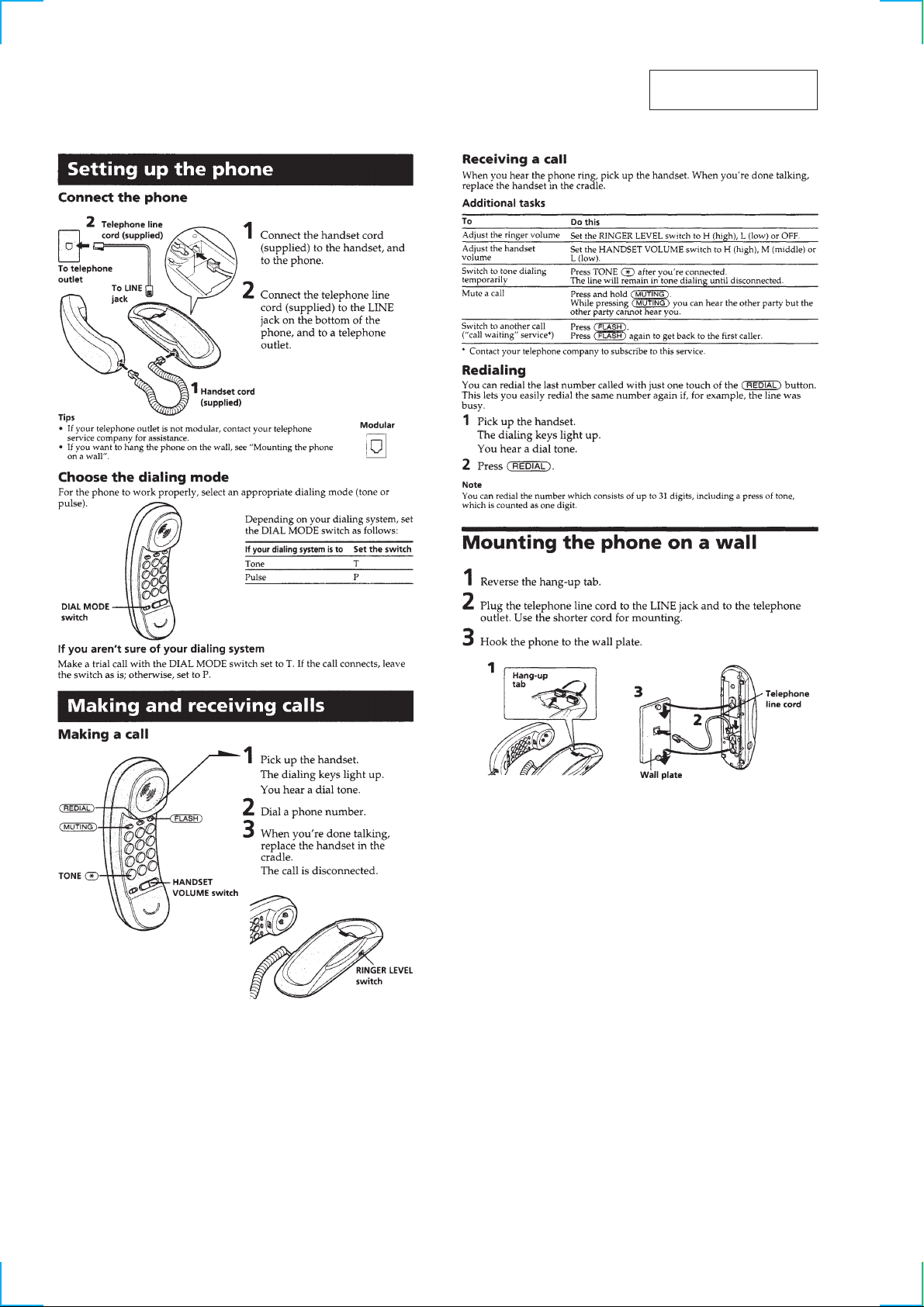
SECTION 1
GENERAL
This section is extracted
from instruction manual.
2
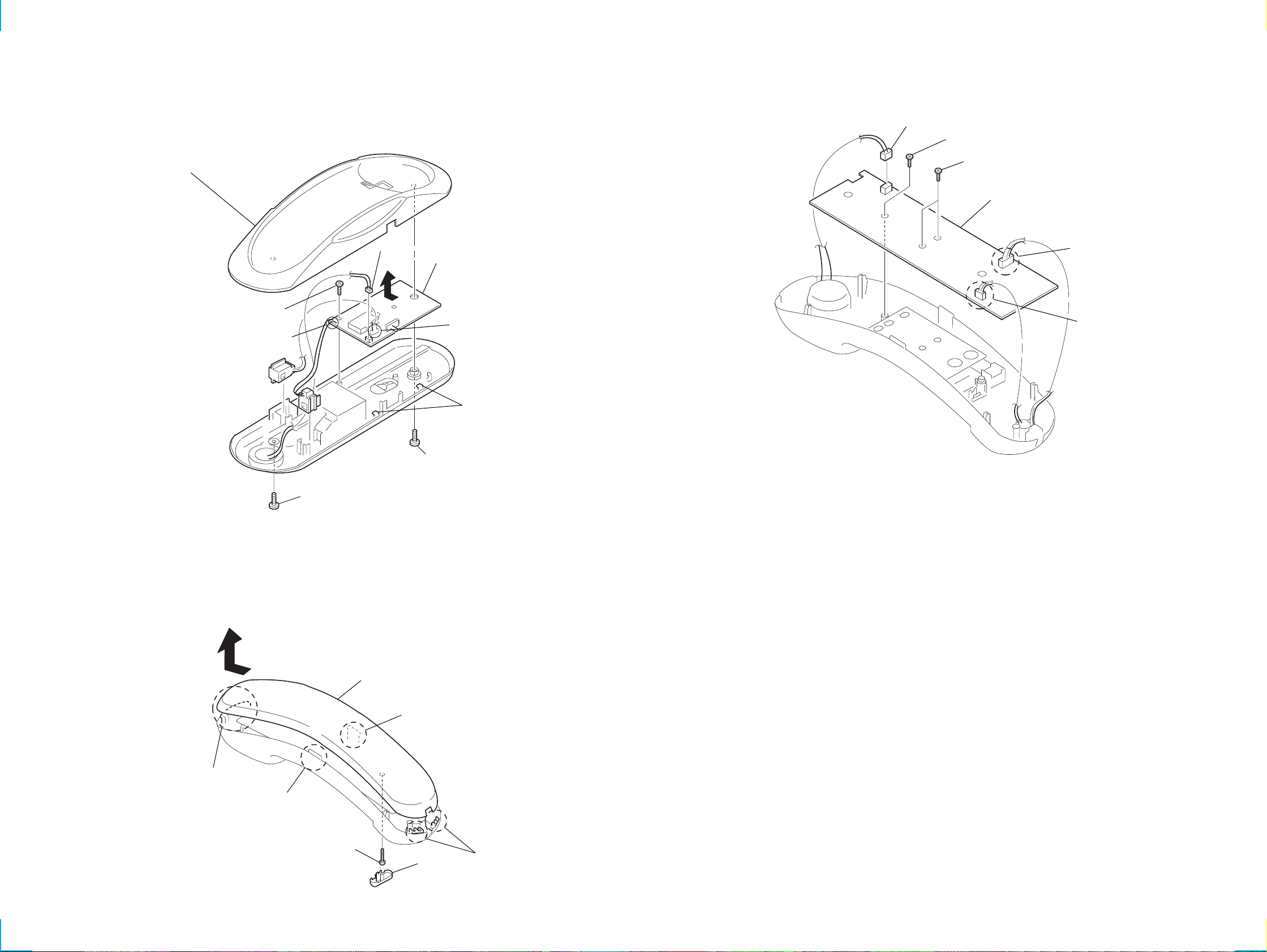
SECTION 2
DISASSEMBLY
Note : Follow the disassembly procedure in the numerical order given.
2-1. CRADLE BOARD
3
cabinet base (upper) assy
5
BTP 2.6x6
8
Removal the solders.
4
CN1
6
9
CRADLE board
7
Removal the solders.
claws
2-3. HAND MAIN BOARD
1
CN5
2
BTP 2.6x6
3
BTP 2.6x6
4
HAND MAIN board
5
Removal the solders.
6
Removal the solders.
2-2. HANDSET (FRONT)
6
7
claw
1
BTP 3x8
8
handset (front)
4
claw
2
BTP 3x8
5
claw
2
P 2.6x16
1
knob
3
claws
33
IT-B1
SECTION 3
DIAGRAMS
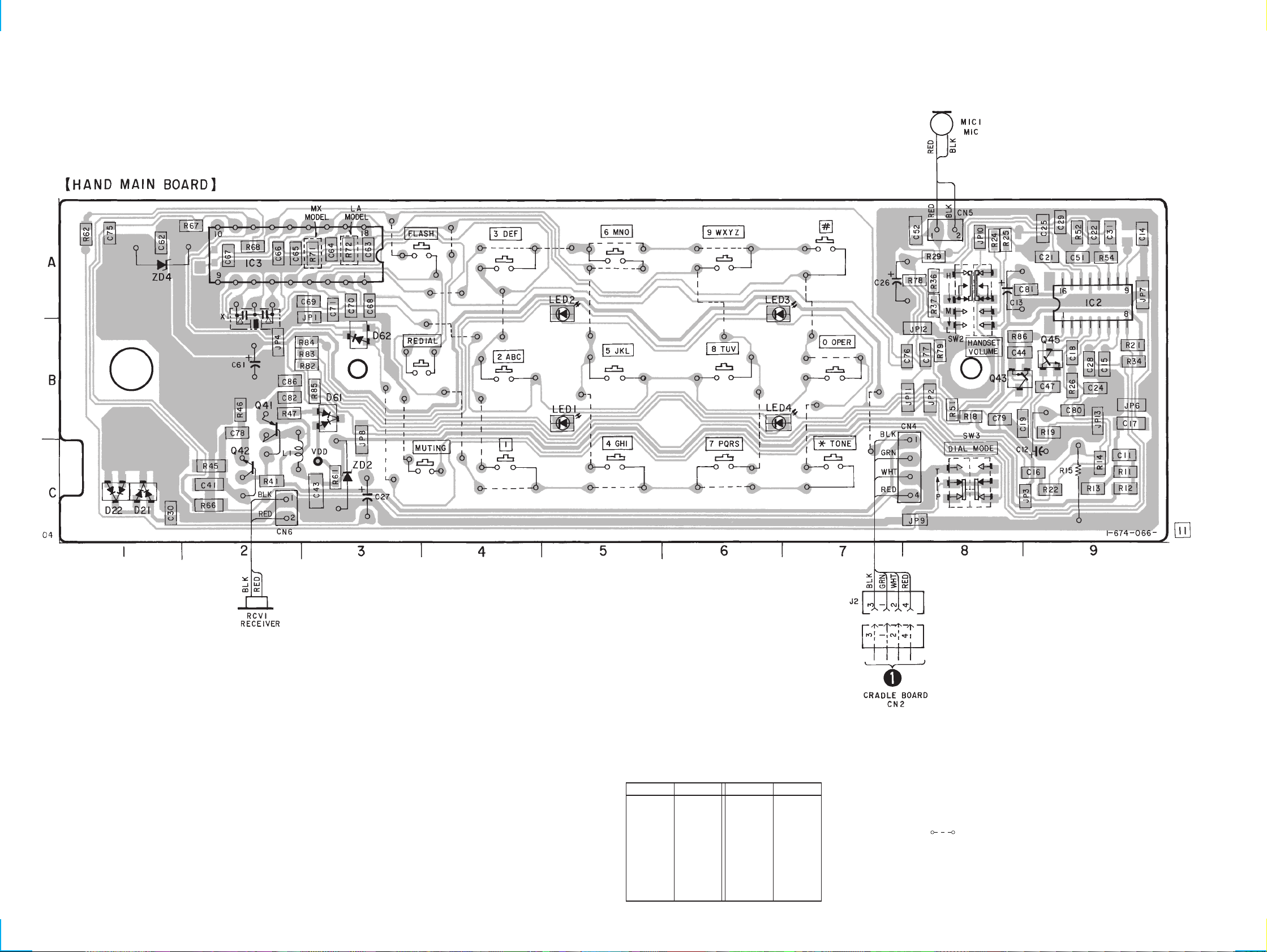
3-1. PRINTED WIRING BOARD — HANDSET SECTION —
• Semiconductor Location
Ref. No. Location
D21 C-1
D22 C-1
D61 B-3
D62 B-3
IC2 A-9
IC3 A-2
LED1 B-5
LED2 A-5
44
Ref. No. Location
LED3 A-6
LED4 B-6
Q41 B-2
Q42 C-2
Q43 B-8
Q45 B-9
ZD2 C-3
ZD4 A-1
Note:
• X : parts extracted from the component side.
• : Carbon pattern.
¢
•
• b : Pattern from the side which enables seeing.
• Abbreviation
: internal component.
(The other layer’s patterns are not indicated.)
MX : Mexican model
LA : Latin American model
 Loading...