

Sony IRF302U Users Manual
LOCATION Free TV LF-X1
4-103-221-11(1)
LOCATION Free
TV
Operating Instructions
LF-X1
© 2004 Sony Corporation
Owner’s Record
The model and serial numbers are located at the
bottom of the base station. Record the serial number
in the space provided below. Refer to them whenever
you call upon your Sony dealer regarding this
product.
Model No. LF-X1
Serial No.____________________________
Contacting Sony
If, after reading these operating instructions, you
have additional questions related to the use of your
Sony television, please call our Customer
Information Services Center at 1-800-222-SONY
(7669) (US residents only) or 1-877-899-SONY
(7669) (Canadian residents only).
Important Safety Instructions
1) Read these instructions.
2) Keep these instructions.
3) Heed all warnings.
4) Follow all instructions.
5) Do not use this apparatus near water.
6) Clean only with dry cloth.
7) Do not block any ventilation openings. Install in
accordance with the manufacturer’s instructions.
8) Do not install near any heat sources such as radiators,
heat registers, stoves, or other apparatus (including
amplifiers) that produce heat.
9) Do not defeat the safety purpose of the polarized or
grounding-type plug. A polarized plug has two blades
with one wider than the other. A grounding type plug
has two blades and a third grounding prong. The wide
blade or the third prong are provided for your safety.
If the provided plug does not fit into your outlet,
consult an electrician for replacement of the obsolete
outlet.
10) Protect the power cord from being walked on or
pinched particularly at plugs, convenience
receptacles, and the point where they exit from the
apparatus.
11) Only use attachments/accessories specified by the
manufacturer.
12) Use only with the cart, stand, tripod, bracket, or table
specified by the manufacturer, or sold with the
apparatus. When a cart is used, use caution when
moving the cart/apparatus combination to avoid injry
from tip-over.
13) Unplug this apparatus during lightning storms or
when unused for long periods of time.
14) Refer all servicing to qualified service personnel.
Servicing is required when the apparatus has been
damaged in any way, such as power-supply cord or
plug is damaged, liquid has been spilled or objects
have fallen into the apparatus, the apparatus has been
exposed to rain or moisture, does not operate
normally, or has been dropped.
2
WARNING
To reduce the risk of fire or shock hazard, do not expose
the TV to rain or moisture.
CAUTION
RISK OF ELECTRIC SHOCK
DO NOT OPEN
ATTENTION
RISQUE DE CHOC ELECTRIQUE,
NE PAS OUVRIR
PRECAUCION
RIESGO DE CHOQUE ELECTRICO
NO ABRIR
CAUTION: TO REDUCE THE RISK OF ELECTRIC SHOCK,
DO NOT REMOVE COVER (OR BACK).
NO USER-SERVICEABLE PARTS INSIDE.
REFER SERVICING TO QUALIFIED SERVICE PERSONNEL.
This symbol is intended to alert the user to
the presence of uninsulated “dangerous
voltage” within the product’s enclosure
that may be of sufficient magnitude to
constitute a risk of electric shock to
persons.
This symbol is intended to alert the user to
the presence of important operating and
maintenance (servicing) instructions in the
literature accompanying the appliance.
This equipment must not be co-located or operating in
conjunction with any other antenna or transmitter.
FCC Radiation Exposure Statement:
The available scientific evidence does not show that any
health problems are associated with using low power
wireless devices. There is no proof, however, that these
low power wireless devices are absolutely safe. Low
power Wireless devices emit low levels of radio
frequency energy (RF) in the microwave range while
being used. Whereas high levels of RF can produce health
effects (by heating tissue), exposure to low level RF that
does not produce heating effects causes no known adverse
health effects. Many studies of low level RF exposures
have not found any biological effects. Some studies have
suggested that some biological effects might occur, but
such findings have not been confirmed by additional
research. The LF-X1 has been tested and found to comply
with the Federal Communications Commission (FCC)
guidelines on radio frequency energy (RF) exposures.
The maximum SAR levels tested for the LF-X1 has been
show to be 0.87 W/kg at Body.
* This transmitter must not be co-located or operating in
conjunction with any other antenna or transmitter.
* When using the unit with 802.11a (5GHz), use in doors.
CAUTION
Danger of explosion if battery is incorrectly
replaced.
Replace only with the same or equivalent type.
This device complies with Part 15 of the FCC Rules.
Operation is subject to the following two conditions:
(1)This device may not cause harmful interference,
and
(2)this device must accept any interference received,
including interference that may cause undesired
operation.
3

NOTIFICATION
This equipment has been tested and found to comply with
the limits for a Class B digital device, pursuant to Part 15
of the FCC Rules. These limits are designed to provide
reasonable protection against harmful interference in a
residential installation. This equipment generates, uses,
and can radiate radio frequency energy and, if not
installed and used in accordance with the instructions,
may cause harmful interference with radio
communications. However, there is no guarantee that
interference will not occur in a particular installation. If
this equipment does cause harmful interference to radio or
television reception, which can be determined by turning
the equipment off and on, the user is encouraged to try to
correct the interference by one or more of the following
measures:
Reorient or relocate the receiving antenna.
Increase the separation between the equipment and
receiver.
Connect the equipment into an outlet on a circuit different
from that to which the receiver is connected.
Consult the dealer or an experienced radio/TV technician
for help.
FCC WARNING
You are cautioned that any changes or modifications not
expressly approved in this manual could void your
authority to operate this equipment.
For customers in the United States
This product contains mercury. Disposal of this product
may be regulated if sold in the United States. For disposal
or recycling information, please contact your local
authorities or the Electronics Industries Alliance
(http://eiae.org).
Pour les clients résidant aux États-Unis
Ce produit contient du mercure. L’élimination de ce
produit peut être soumise à réglementation s’il est vendu
aux États-Unis. Pour obtenir des informations concernant
l’élimination ou le recyclage, veuillez contacter les
autorités locales ou l’Electronics Industries Alliance
(http://www.eiae.org).
4

Table of Contents
Locating the Components...................................................................................... 6
Checking the Package Contents ............................................................................ 9
Connecting a Cable or an Antenna...................................................................... 10
Connecting Video/Audio Equipment .................................................................. 10
Turning On the Power ......................................................................................... 13
Connecting to the Internet ................................................................................... 15
Configuring Network Settings............................................................................. 17
Setting Up for Mail.............................................................................................. 20
Watching TV and Video...................................................................................... 21
Basic TV/Video Screen ....................................................................................... 22
Viewing Web Pages............................................................................................. 23
Basic Internet Screen........................................................................................... 24
Using E-mail........................................................................................................ 25
Basic E-mail Screen............................................................................................. 25
Viewing Enlarged Images ................................................................................... 28
Basic Digital Photo Album Screen...................................................................... 29
Specifications....................................................................................................... 30
5
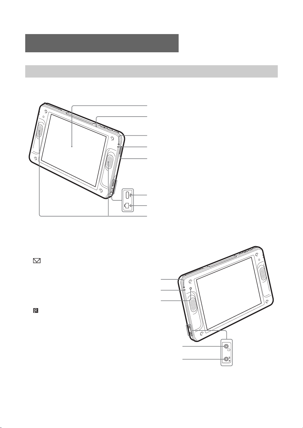
Locating the Components
8
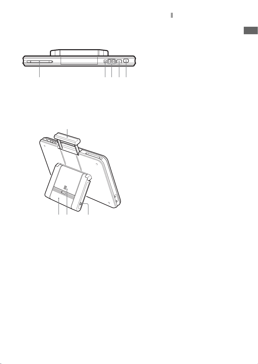
Monitor
Right side
Left side
1LCD (Liquid Crystal Display)
2POWER indicator
1
2
3
4
5
6
7
Lights green when the power is on.
3WIRELESS indicator
Indicates the status of wireless communications.
Lights blue: Communications using the 5 GHz
channel are in progress.
Lights green: Communications using the 2.4 GHz
channel are in progress.
Off: No radio waves are being output.
4“Memory Stick” indicator
Lights orange while the unit and the inserted
“Memory Stick” are communicating.
5“Memory Stick” slot
Insert a “Memory Stick.”
6USB connector
Connect a commercially available keyboard.
7LAN connector
Connect a LAN cable.
8Speakers
9 Mail Auto Receive indicator
Lights red when new e-mail is received through
periodical e-mail check.
0e Charge indicator
Indicates the status of charging.
Lights red: Charging the battery is in progress.
Off: Charging finished.
qa Infrared receiver
qsi Headphones jack (stereo minijack)
qdAV IN connector
6
9
0
qa
qs
qd
Locating the Components
q
qkq
qhq
q
w;w
w
R
Top
ear
qfStylus pen compartment
qgPOWER switch
Turns on and off the power to the monitor.
qhVOLUME +/– buttons
Adjusts the volume of the speakers.
qjCAPTURE button
Saves the currently displayed screen in an
f
j
g
album as a still image.
qkINDEX button
Displays the Index window.
qlMonitor handle
l
w;Monitor stand
waBattery
wsDC IN connector
Connect the AC power adaptor (supplied) for
the monitor.
a
s
7
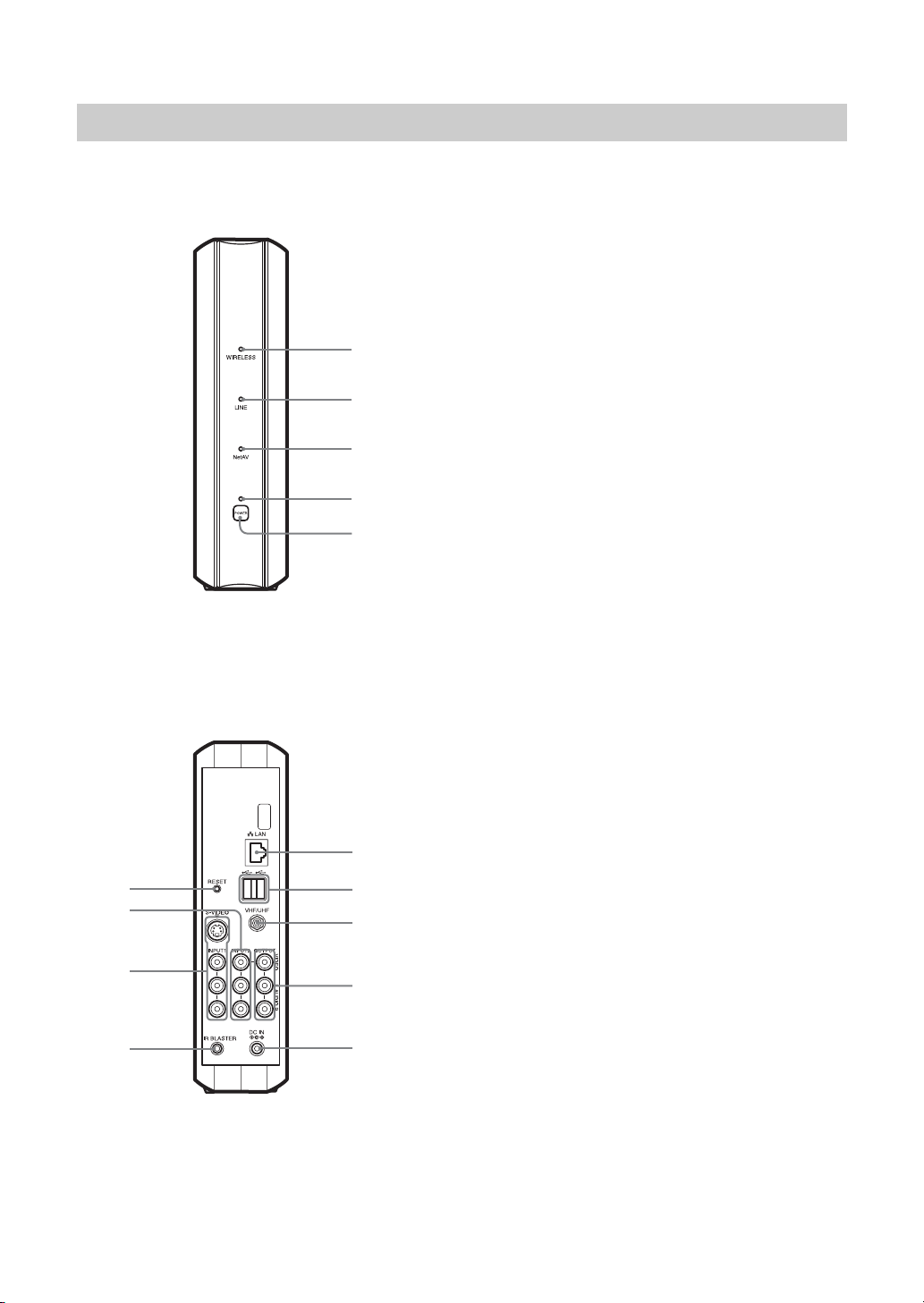
Base Station
Front
Rear
qf
qd
qs
qa
1
2
3
4
5
6
7
8
9
0
1WIRELESS indicator
Indicates the status of wireless communications.
Lights blue: Communications using the 5 GHz channel are
in progress.
Lights green:Communications using the 2.4 GHz channel
are in progress.
2LINE indicator
Indicates the connection status to an external network such
as the Internet.
Blinks green: Connection is being made.
Lights green: Connection has been made.
Off: Connection has not been made.
3NetAV indicator
Indicates the connection status when connection with the
monitor has been made using the NetAV function.
Lights green: Connection to the NetAV has been made.
Off: Connection to the NetAV has not been made.
4POWER indicator
Lights green when the power to the base station is on.
5POWER switch
Turns on and off the power to the base station.
6LAN connector
Connect a LAN cable.
7USB connector
8VHF/UHF connector
Connect an antenna connection cable.
9VIDEO LINE OUTPUT (AUDIO/VIDEO) jacks
Output signals that are input to the video input 2 jack.
Connect audio and video cables.
0DC IN connector
Connect the AC power adaptor (supplied) for the base
station.
qaIR BLASTER connector
Connect the AV mouse (supplied).
qsVIDEO LINE INPUT1 (S-VIDEO/AUDIO/VIDEO) jacks
Connect S-video and audio cables; or connect audio and
video cables.
qdVIDEO LINE INPUT2 (AUDIO/VIDEO) jacks
Connect audio and video cables.
qfBASESTATION RESET button
Returns all settings including line and wireless
communications settings on the base station to the factory
defaults.
8

Checking the
Package Contents
After unpacking, check that all the following
items have been included:
• Base station (× 1)
• Monitor (× 1)
•Stylus (×1)
• BP-LX1A battery (× 1)
• AC-LX1B AC power adapter for the base
station (× 1)
• AC-LX1M power adaptor for the monitor (× 1)
•Power cord (×2)
•AV mouse (×1)
• Base station stand (× 1)
Checking the Package Contents
9
Connecting a Cable
Connecting Video/
or an Antenna
Connecting a TV and Cable/
Antenna
When you have connected your TV to the CATV
cable or antenna, use this hookup.
With this hookup, set Cable to OFF in the Auto
CH Program window of Settings TV/Video.
1
Turn off the power of your TV and remove
the antenna or CATV cable from the antenna
input of your TV.
2
Plug the OUT connector of the supplied
antenna connector into the antenna input of
your TV.
3
Plug the antenna or CATV cable removed
from your TV in step 1 into the ANT
connector of the supplied antenna connector.
Audio Equipment
Connecting a Cable Box
Use this hookup if you subscribe to a cable TV
system that uses scrambled or encoded signals
requiring a cable box to view all channels.
1
Connect the coaxial connector from your
cable service to the IN connector of the cable
box.
2
Using a coaxial cable, connect the OUT
connector of the cable box to the VHF/UHF
connector of the base station.
With this hookup, set Cable to ON in the Auto
CH Program window of Settings TV/Video.
Caution
To change channels using the cable box, set your
Wireless Home Network TV to channel from 1 to 6,
depending on the cable box channel output.
4
Plug the output cord of the antenna
connector into the VHF/UHF connector of
the base station.
* If the output cord of the supplied antenna
connector is short, use the optional EAC-40 TV
antenna connector.
To connect the base station only to
the antenna or CATV cable directly
Use the optional EAC-315 or equivalent antenna
cable.
10
Connecting a VCR and Cable/
Antenna
Use this hookup if you have cable TV that does
not require a cable box.
1
Disconnect all power sources.
2
Connect the CATV cable or antenna to the
VHF/UHF IN connector of the VCR.
3
Using a coaxial cable, connect the VHF/
UHF OUT connector of the VCR to the
VHF/UHF connector of the base station.
 Loading...