

Sony IPELS SNC-RZ50N, IPELS SNC-RZ50P, IPELA SNC-RZ50N, IPELA SNC-RZ50P Installation Manual
3-276-339-11 (1)
Network Camera
Installation Manual
Before operating the unit, please read this manual thoroughly
and retain it for future reference.
SNC-RZ50N/RZ50P
2007 Sony Corporation
3276339110
Printed on 70% or more recycled paper.
Printed in Japan
Owner’s Record
The model and serial numbers are located on the bottom. Record these
numbers in the spaces provided below.
Refer to these numbers whenever you call upon your Sony dealer
regarding this product.
Model No. Serial No.
WARNING
To reduce a risk of fire or electric shock, do not
expose this product to rain or moisture.
To avoid electrical shock, do not open the cabinet.
Refer servicing to qualified personnel only.
AC power adaptor
Model No.: MPA-AC1 (Sony)
CAUTION: This unit is for use only with the supplied AC power adaptor.
Use with other AC power adaptors may cause hazards such as a fire.
WARNING
This installation should be made by a qualified service person and
should conform to all local codes.
WARNING
A readily accessible disconnect device shall be incorporated in the
building installation wiring.
WARNING (for Installers only)
Instructions for installing the equipment on the ceiling:
After the installation, ensure the connection is capable of supporting five
times the weight of the equipment downwards.
CAUTION
The rating label is located on the bottom.
CAUTION for LAN port
For safety reason, do not connect the LAN port to any network devices
that might have excessive voltage.
For customers in the U.S.A. (SNC-RZ50N only)
This device complies with Part 15 of the FCC Rules. Operation is
subject to the following two conditions: (1) This device may not
cause harmful interference, and (2) this device must accept any
interference received, including interference that may cause
undesired operation.
NOTE: This equipment has been tested and found to comply with the
limits for a Class A digital device, pursuant to part 15 of the FCC Rules.
These limits are designed to provide reasonable protection against
harmful interference when the equipment is operated in a commercial
environment. This equipment generates, uses, and can radiate radio
frequency energy and, if not installed and used in accordance with the
instruction manual, may cause harmful interference to radio
communications. Operation of this equipment in a residential area is
likely to cause harmful interference in which case the user will be
required to correct the interference at his own expense.
CAUTION
You are cautioned that any changes or modifications not expressly
approved in this manual could void your authority to operate this
equipment.
All interface cables used to connect peripherals must be shielded in
order to comply with the limits for a digital device pursuant to Subpart B
or Part 15 of FCC Rules.
For customers in Canada (SNC-RZ50N only)
This Class A digital apparatus complies with Canadian ICES-003.
Cet appareil numérique de la classe A est conforme à la norme NMB003 du Canada.
For customers in other countries
WARNING
This is a Class A product. In a domestic environment, this product may
cause radio interference in which case the user may be required to take
adequate measures.
In the case that interference should occur, consult your nearest
authorized Sony service facility.
ATTENTION
The electromagnetic fields at specific frequencies may influence the
picture of the unit.
Voor de Klanten in Nederland
• Gooi de batterij niet weg maar lever deze in als klein chemisch afval
(KCA).
• Dit apparaat bevat een vast ingebouwde batterij die niet vervangen
hoeft te worden tijdens de levensduur van het apparaat.
• Raadpleeg uw leverancier indien de batterij toch vervangen moet
worden. De batterij mag alleen vervangen worden door vakbekwaam
servicepersoneel.
• Lever het apparaat aan het einde van de levensduur in voor
recycling, de batterij zal dan op correcte wijze verwerkt worden.
Features
• You can monitor a high-quality live image from the camera using the Web
browser on a computer connected to a 10BASE-T or 100BASE-TX
network.
• The maximum frame rate is 30 fps for SNC-RZ50N and 25 fps for SNCRZ50P.
• Up to 20 users can view an image from one camera at the same time.
• Single codec mode and Dual codec mode swichable.
• Remote-controllable high-speed pan/tilt mechanism and high
magnification autofocus zoom lens are provided.
• Inserting the optional wireless card SNCA-CFW1* (802.11b) or SNCACFW5* (802.11b or 802.11g) in the CF card slot or PC card slot enables
you to transmit images from the camera via wireless LAN.
• Image transmission using e-mail or FTP is possible.
• Up to 16 preset positions (pan, tilt and zoom positions) of the camera and
5 tour programs composed from the preset positions can be saved.
• The camera is provided with an intelligent object detection function.
• Two sets of alarm outputs are equipped, which enables you to control
peripheral devices by synchronizing with any functions.
• Direct panning/tilting function is equipped.
• Builted-in superimposed function (date/time).
* SNCA-CFW1 and SNCA-CFW5 are not available in some countries and areas.
For details, contact your authorized Sony dealer.
Notes on Use
Data and security
• You should keep in mind that the images or audio you are monitoring
may be protected by privacy and other legal rights, and the responsibility
for making sure you are complying with applicable laws is yours alone.
• Access to the images and audio is protected only by a user name and the
password you set up. No further authentication is provided nor should
you presume that any other protective filtering is done by the service.
Since the service is Internet-based, there is a risk that the image or audio
you are monitoring can be viewed or used by a third-party via the
network.
• SONY IS NOT RESPONSIBLE, AND ASSUMES ABSOLUTELY NO
LIABILITY TO YOU OR ANYONE ELSE, FOR SERVICE
INTERRUPTIONS OR DISCONTINUATIONS OR EVEN SERVICE
CANCELLATION. THE SERVICE IS PROVIDED AS-IS, AND SONY
DISCLAIMS AND EXCLUDES ALL WARRANTIES, EXPRESS OR
IMPLIED, WITH RESPECT TO THE SERVICE INCLUDING, BUT NOT
LIMITED TO, ANY OR ALL IMPLIED WARRANTIES OF
MERCHANTABILITY, FITNESS FOR A PARTICULAR PURPOSE, OR
THAT IT WILL OPERATE ERROR-FREE OR CONTINUOUSLY.
• Security configuration is essential for wireless LAN. Should a problem
occur without setting security, or due to the limitation of the wireless LAN
specifications, SONY shall not be liable for any damage.
• Always make a test recording, and verify that it was recorded
successfully. SONY WILL NOT BE LIABLE FOR DAMAGES OF ANY
KIND INCLUDING, BUT NOT LIMITED TO, COMPENSATION OR
REIMBURSEMENT ON ACCOUNT OF FAILURE OF THIS UNIT OR ITS
RECORDING MEDIA, EXTERNAL STORAGE SYSTEMS OR ANY
OTHER MEDIA OR STORAGE SYSTEMS TO RECORD CONTENT OF
ANY TYPE.
• Always verify that the unit is operating properly before use. SONY WILL
NOT BE LIABLE FOR DAMAGES OF ANY KIND INCLUDING, BUT NOT
LIMITED TO, COMPENSATION OR REIMBURSEMENT ON ACCOUNT
OF THE LOSS OF PRESENT OR PROSPECTIVE PROFITS DUE TO
FAILURE OF THIS UNIT, EITHER DURING THE WARRANTY PERIOD
OR AFTER EXPIRATION OF THE WARRANTY, OR FOR ANY OTHER
REASON WHATSOEVER.
• If you lose data by using this unit, SONY accepts no responsibility for
restoration of the data.
Operating or storage location
Do not shoot an extremely bright object (an illumination, the sun, etc.). Also,
avoid operating or storing the camera in the following locations, as these
can be a cause of a malfunction.
• Extremely hot or cold places (Operating temperature: 0 °C to
+40 °C [32 °F to 104 °F])
• Exposed to direct sunlight for a long time, or close to heating equipment
(e.g., near heaters)
• Close to sources of strong magnetism
• Close to sources of powerful electromagnetic radiation, such as radios or
TV transmitters
• Locations subject to strong vibration or shock
Ventilation
To prevent heat buildup, do not block air circulation around the camera.
Transportation
When transporting the camera, repack it as originally packed at the factory
or in materials of equal quality.
Cleaning
• Use a blower to remove dust from the lens.
• Use a soft, dry cloth to clean the external surfaces of the camera.
Stubborn stains can be removed using a soft cloth dampened with a
small quantity of detergent solution, then wipe dry.
• Do not use volatile solvents such as alcohol, benzene or thinners as they
may damage the surface finishes.
Note on laser beams
Laser beams may damage a CCD. You are cautioned that the surface of a
CCD should not be exposed to laser beam radiation in an environment where
a laser beam device is used.
Phenomena Specific to CCD Image Sensors
The following phenomena that may appear in images are specific to CCD
(Charge Coupled Device) image sensors. They do not indicate
malfunctions.
White flecks
Although the CCD image sensors are produced with high-precision
technologies, fine white flecks may be generated on the screen in rare
cases, caused by cosmic rays, etc.
This is related to the principle of CCD image sensors and is not a
malfunction.
The white flecks especially tend to be seen in the following cases:
- when operating at a high environmental temperature
- when you have raised the gain (sensitivity)
- when using the slow shutter
Vertical smear
When an extremely bright object, such as a strong spotlight or flashlight, is
being shot, vertical tails may be produced on the screen, or the image may
be distorted.
Aliasing
When fine patterns, stripes, or lines are shot, they may appear jagged or
flicker.
About the Supplied Manuals
Installation Manual (this document)
This Installation Manual describes the names and functions of parts and
controls of the Network Camera, gives connection examples and explains
how to set up the camera. Be sure to read the Installation Manual before
operating.
User’s Guide (stored in the CD-ROM)
The User’s Guide describes how to set up the camera and how to control
the camera via a Web browser.
After installing and connecting the camera correctly, operate referring to this
User’s Guide.
Using the CD-ROM Manuals
The supplied CD-ROM disc includes the User’s Guides for this unit
(Japanese, English, French, German, Spanish, Italian and Chinese
versions) in PDF format.
Preparations
The Adobe Reader Version 6.0 or higher must be installed on your
computer in order to use the User’s Guide stored in the CD-ROM disc.
Note
If Adobe Reader is not installed, it may be downloaded from the following
URL: http://www.adobe.com/
Reading the manual in the CD-ROM
1 Insert the CD-ROM in your CD-ROM drive.
A cover page appears automatically in your Web browser.
If it does not appear automatically in the Web browser, double-click on
the index.htm file on the CD-ROM.
2 Select and click on the manual that you want to read.
This opens the PDF file of the manual.
Clicking an item in the Table of Contents allows you jump to the relevant
page.
Notes
• The files may not be displayed properly, depending on the version of
Adobe Reader. In this case, install the latest version, which you can
download from the URL mentioned in “Preparations” above.
• If you have lost or damaged the CD-ROM, you can purchase
replacement. Contact your Sony service representative.
Adobe, Acrobat and Acrobat Reader are trademarks of Adobe Systems
Incorporated in the United States and/or other countries.
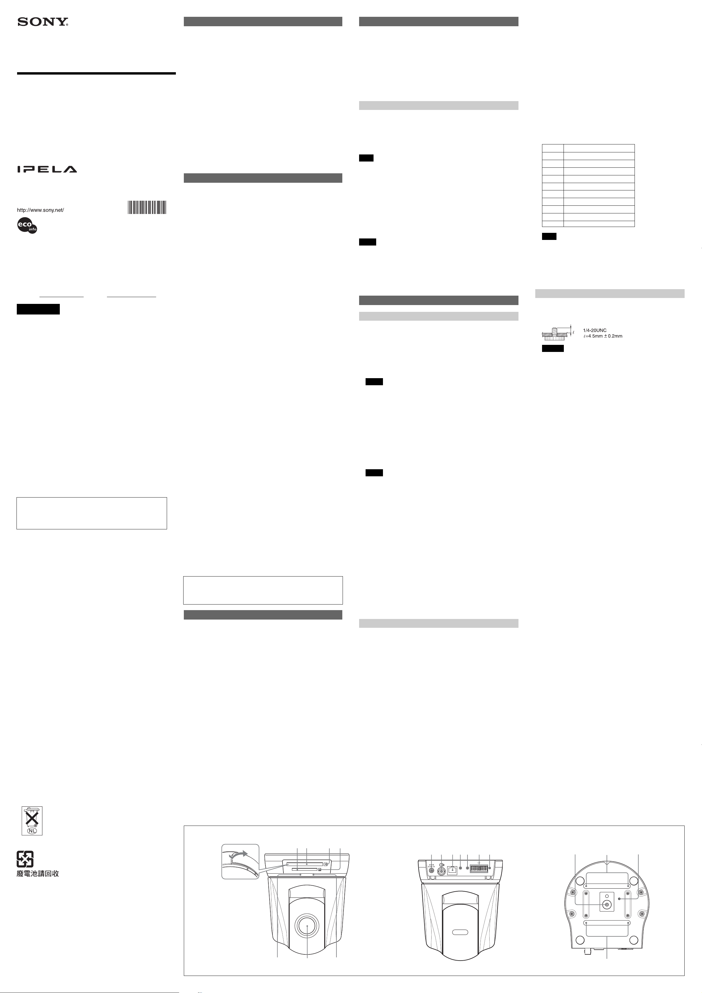
Location and Function of Part
Front A
1 CF card slotA longer wireless LAN distance can be obtained by
attaching the optional SNCA-AN1 wireless LAN antenna to the
SNCA-CFW1* or SNCA-CFW5*.
This slot is used for the optional SNCA-CFW1* (802.11b)/SNCA-CFW5*
(802.11b or 802.11g) wireless card or recommended CF memory card.
A longer wireless LAN distance can be obtained by attaching the optional
SNCA-AN1 wireless LAN antenna to the SNCA-CFW1* or SNCACFW5*.
Notes
• Insert the CF memory card with its front side towards the NETWORK
indicator.
• For the verified CF memory cards, contact your authorized Sony
dealer.
2 PC card slot
This slot is used for the optional SNCA-CFW1*/SNCA-CFW5* wireless
card or recommended ATA memory card.
In case of the wireless card: Insert the SNCA-CFW1* into a
commercially available type II-PCMCIA adaptor and insert the adaptor
into the PC card slot.
A longer wireless LAN distance can be obtained by attaching the optional
SNCA-AN1 wireless LAN antenna to the SNCA-CFW1* or SNCACFW5*.
Notes
• Insert the PC card with its front side towards the bottom of the camera.
• For the verified ATA memory cards, contact your authorized Sony
dealer.
3 PC card lever
Press the lever to remove the PC card from the PC card slot.
4 CF card lever
Press the lever to remove the CF memory card from the CF card slot.
5 NETWORK indicator (green)
The indicator lights up or flashes in green when the camera is connected
to the network.
The indicator goes off when the camera is not connected to the network.
6 Lens
A × 26 optical zoom, auto-focus lens is mounted as standard equipment.
7 POWER indicator (green)
When the power is supplied to the camera, the camera starts checking
the system.
If the system works normally, this indicator lights up.
If a system error occurs, this indicator flashes every second. In this case,
consult your authorized Sony dealer.
* SNCA-CFW1 and SNCA-CFW5 are not available in some countries and areas.
For details, contact your authorized Sony dealer.
Rear
8 DC IN 12 V (power input) connector
Connect the supplied AC power adaptor.
9 T (video output) connector (BNC type)
Outputs a composite video signal. Connect to a composite video input
connector of a video monitor, etc.
q; LAN (network) port (RJ45)
Connect to the 10BASE-T or 100BASE-TX network using a network
cable (UTP, category 5).
qa m (microphone input) jack (minijack, monaural)
Connect a commercially available microphone. This jack supports plugin-power microphones (rated voltage: 2.5 V DC).
You can connect the microphones of the following specifications to this
camera.
Type: Electret condenser microphone Plug-in power system
Directivity: Omni-directional
Sensitivity: –40 ± 3.5 dB
Frequency range: 50 – 15,000 Hz
Plug: ø3.5 Mini-plug
B
qs 5 (line output) jack (minijack, monaural)
Connect a commercially available speaker system with the built-in
amplifier.
You can connect the speakers of the following specifications to this
camera.
Type: Active speaker
Impedance: Input impedance 4.7 kohms or more
Plug: ø3.5 Mini-plug
qd I/O (Input/Output) port
This port is provided with an RS-232C port, two sensor inputs and
two alarm outputs.
The RS-232C port is used when you connect peripheral devices to
the camera using the RS-232C interface, and control the camera or
transmit/receive data from the devices.
The sensor input is used as the alarm input. The camera operation
can be synchronized with e-mail (SMTP) or other applications.
The alarm output is used to control connected peripheral devices by
synchronizing with an external sensor input, the built-in detection
function, a manual trigger button, Day/Night function or the timer
function.
Pin No. Pin name
1 Sensor In 1 +
2 Sensor In 1 – (GND)
3 Sensor In 2 +
4 Sensor In 2 – (GND)
5 Alarm Out 1 +
6 Alarm Out 1 –
7 Alarm Out 2 +
8 Alarm Out 2 –
9 RS232C . RX
10 RS232C . TX
Note
The I/O port of this unit corresponds to the VISCA command.
However, there are some commands which are not supported.
qf Reset switch
To reset the camera to the factory default settings, supply the power
to the camera, while holding down this switch with a pointed object.
For details on each function and required settings, see the User’s
Guide stored in the supplied CD-ROM.
Bottom
qg Tripod hole
Use this hole when attaching the camera to a tripod (screw: 1/4”, 20
UNC)
Caution
Use the mounting screw whose length is 4.5 mm ± 0.2 mm only.
Use of other screws may cause improper mounting and damage
parts inside the camera.
qh Ceiling bracket mounting screw holes
When installing the camera on the ceiling, fix the supplied ceiling
brackets to these holes using the supplied screws (3M3 × 6).
qj Screw hole for fall-prevention wire rope
When installing the camera on the ceiling, fix the supplied fallprevention wire rope to this hole using the supplied shoulder screw
(3M4).
(continued on the reverse side)
C
For the customers in Taiwan only
ABC
21
576
34
8 9 0 qa qs qfqd
CLASS 2 WIRING SEE INSTRUCTION MANUAL
LAN
10 987654321
5
m
qh
qh
qjqg
D
1, 2
Ceiling
Fall-prevention
wire rope
F
Installation
Notes
• Do not grasp the camera head when carrying the camera.
• Do not turn the camera head manually. Doing so will result in the camera
malfunctioning.
Wiring diagram for alarm output
Camera inside
5 or 7 pin
(Alarm Output +)
5 V
Outside
3
Set the
triangular hole at
the front of the
camera
4
5
6
8
E
Front of the
camera
Shoulder screw
3M4 (supplied)
Upper ceiling
bracket
3M3×6
(supplied)
1
Ceiling
Fall-prevention wire rope
Ceiling
Mounting
bracket cover
(supplied)
Ceiling
Tab
Upper ceiling
bracket
Ceiling
3M3×6
(supplied)
Lower ceiling
bracket
Ceiling
3M3×6
(supplied)
Hole for
connecting cables
Lower ceiling
bracket
G
To an AC
outlet
H
10 9 8 7 6 5 4 3 2 1
Slotted
screwdriver
I
1
J
Front
Side
70 (2 7/8)
Bottom
Screw hole for
wire rope
Upper ceiling bracket
ø 96
40°
Hole 4 –
3
ø4.4 (
/16)
Sony MPA-AC1
AC power adapter
(Supplied)
I/O
Wire
140 (5 5/8)
72 (2 7/8)
(Adjustable range:±20°)
30°
,
SNC-RZ50N/RZ50P (rear)
CLASS 2 WIRING SEE INSTRUCTION MANUAL
LAN
Network
10 987654321
5
m
LAN
Network cable
(straight, not supplied)
10BASE-T/
100BASE-TX
Hub
,
2
Lithium
battery
Front (with ceilling brackets)
)
8
/
5
166 (6
Side (with cable cover)
9 (3/8)
70 (2 7/8) 142 (5 5/8)
70 (2 7/8)
Hole 4 – M3 (×4)
83.5 (3 3/8)
40°
30°
3M3×6
Plug retalner
(supplied)
10 9 8 7 6 5 4 3 2 1
140 (5 5/8)
ø88.9 (3 1/2)
Hole width 4.4 (3/16) (×4)
40°
Unit: mm (inches)
(supplied)
I/O
ø107.3 (4 1/4)
Hole width 4.4 (3/16) (×4)
ø121.2 (4 7/8)
Hole width 4.4 (3/16) (×4)
ø83.5 (3 3/8)
Hole width 4.4 (3/16) (×2)
)
16
/
15
46 (1
)
8
/
1
178 (7
3
)
4
/
44 (1
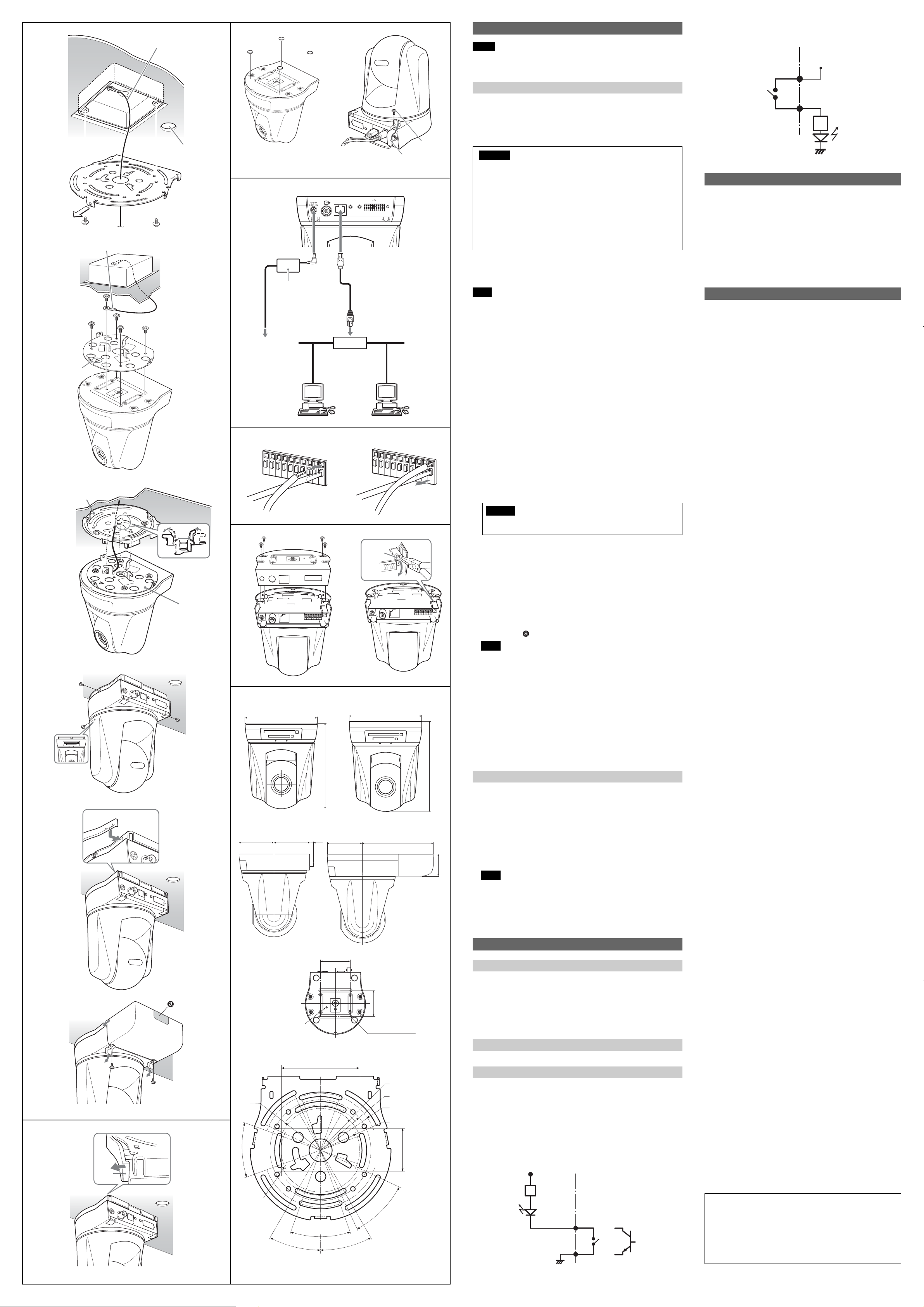
Installing the Camera on the Ceiling D
Using the supplied ceiling brackets, wire rope and screws, you can utilize
existing junction boxes, etc., to attach the camera to the ceiling.
When you install the camera, always install it on a level ceiling. If you have
to install it on a sloping or uneven ceiling, make sure that the place where
you install it is within ±5 degrees of the horizontal in order to ensure the pan/
tilt mechanism functions properly.
Warning
• If you attach the camera in the height such as the wall or the ceiling,
etc., entrust the installation to an experienced contractor or installer.
• If you install the camera on the ceiling, ensure that the ceiling is
strong enough to withstand the weight of the camera plus the ceiling
brackets and then install the camera securely. If the ceiling is not
strong enough, the camera may fall and cause serious injury.
• To prevent the camera from falling, make sure to attach the supplied
wire rope.
• If you attach the camera to the ceiling, check periodically, at least
once a year, to ensure that the connection has not loosened. If
conditions warrant, make this periodic check more frequently.
Before installation
After deciding the direction in which the camera will shoot, make the
required holes for the junction box, and connecting cables.
Note
The connecting cables cannot be passed through the upper ceiling bracket.
A hole for the wiring is required in the ceiling at the back of the camera
where it is attached to the ceiling.
Installation
1 Attach the fall-prevention wire rope to the junction box in the ceiling.
Use a screw hole and a screw (not supplied) in the junction box to attach
the wire rope.
2 Attach the upper ceiling bracket to the junction box on the ceiling.
Align the holes in the bracket with those in the junction box, and use
appropriate screws (not supplied).
There are elongated holes for the screws along the rounded edges of the
upper ceiling bracket. Later, the front of the camera will be positioned
along this edge. Face the camera toward the front, adjust the aim, and
attach it securely.
3 Attach the lower ceiling bracket to the bottom of the camera using the
supplied four screws (3M3 × 6).
Attach also the wire rope to the bottom of the camera using the supplied
shoulder screw (3M4).
When attaching, align the screw holes on the bottom of the camera with
those in the ceiling bracket, and set the triangular hole in the ceiling
bracket at the front of the camera.
Tighten the screws a little bit at a time in the numbered order shown in
the illustration. After all of the screws are temporarily tightened in the
proper manner, securely tighten each one in turn.
Caution
To attach the ceiling bracket, use only the screws supplied with the
camera. Using other screws may damage the camera.
4 Insert the raised protrusions on the lower ceiling bracket into the spaces
provided in the upper ceiling bracket, and temporarily fix them by turning
the camera with lower ceiling bracket clockwise.
5 Attach it using the supplied three screws (3M3 × 6), starting with the
screw at position 1.
6 Attach the mounting bracket cover around the ceiling bracket.
7 Connect the cables to the connectors on the rear of the camera.
8 Temporarily attach the cable cover by inserting the raised protrusions on
the cable cover into the gaps at the rear of the upper ceiling cover. Then
fix the cable cover using the supplied two screws (3M3 × 6).
To extend the cables through the rear of the cable cover, cut out the
thinner portion of the cover using a cutter knife.
Note
Take proper steps to ensure that the load of the connected cables does
not cause problems.
Removing the camera
1 Remove two screws used to attach the cable cover in step 8 of
“Installation” and remove the cable cover.
2 Disconnect the cables from the connectors at the rear of the camera.
3 Remove the mounting bracket cover that is attached in step 6 of
“Installation”E.
First take off the tab on the edge as in the illustration.
4 Remove three screws used to attach the camera in step 5 of
“Installation.”
5 Pushing the entire camera up towards the ceiling, turn the camera
counterclockwise as far as it goes, then pull it out.
Installing the Camera on the Desk Top F
When you install the camera, always install it on a level surface. If you have
to install it on a sloping or uneven surface, make sure that the place where
you install it is within ±5 degrees of the horizontal in order to ensure the pan/
tilt mechanism functions properly. In this case, be sure to take the fallprevention measures.
1 Paste the supplied four rubber feet on the bottom of the camera.
2 Turn the Sony badge on the front to fit top and bottom.
3 Connect the AC power adaptor and attach the plug retainer using the
supplied screw (3M3 × 6) to prevent it coming out.
4 Place the camera on the desktop.
Note
By default, the images from the camera are displayed normally when the
camera is installed on the ceiling. To display the images from the camera
in correct way when you place the camera on the desk top, use the E.flip
function.
For the setting of the E.flip function, see the User’s Guide stored in the
supplied CD-ROM.
Connection
Connecting to the network G
Connect the LAN port of the camera unit to a router or hub in the network
using the network cable (straight, not supplied).
Arrange wiring of the network cable and secure it with the cable clamps, as
shown in the figure.
To connect to a computer
Connect the LAN port of the camera unit to the network connector of a
computer using the network cable (cross, not supplied).
Connecting the power source G
Connect the supplied Sony MPA-AC1 AC power adaptor as shown in figure.
Connecting the I/O cable H
Using the I/O receptacle
While holding down the button under the slot to which you want to connect
the wire (AWG No. 28 to 22) with a small slotted screwdriver, insert the wire
into the slot. Then release the screwdriver from the button.
Repeat this procedure to connect all required wires.
Wiring diagram for sensor input
Mechanical switch/open collector output device
Camera inside
3.3 V
2.35 kohms
Mechanical
switch
1 or 3 pin
(Sensor In +)
2 or 4 pin
(GND)
GND
Outside
or
Open collector
output device
Magnet relay
24 V AC/24 V DC,
1 A or less
6 or 8 pin
(Alarm Output –)
Circuit example
R
GND
When You Discard the Camera I
For environmental reasons, take out the lithium battery from the
camera and discard it appropriately.
1 Remove the four screws illustrated below and detach the bottom
panel.
2 Hold the board on which the lithium battery is attached using long-
nose pliers. Then, bend it in the direction of the arrow illustrated
below to detach the battery.
WARNING (for service personnel only)
There is danger of explosion if batteries are mishandled.
Dispose of batteries properly in accordance with the manufacturer’s
instructions and all applicable local regulations.
Specifications
Network
Protocol TCP/IP, ARP, ICMP, HTTP, HTTPS* FTP
* The model on sale in China does not support the HTTPS
(SSL) function.
Compression
Video compression format JPEG/MPEG4/H.264
Audio compression format G.711/G.726 (40,32,24,16 kbps)
Image size 640 × 480 (VGA), 320 × 240 (QVGA),
Maximum frame rate SNC-RZ50N: 30 fps
Web browser Internet Explorer Ver. 6.0 or later
Available OS Microsoft Windows 2000, Windows XP,
Computer environments CPU: Pentium 4, 1.5 GHz or higher
Maximum user access 20 users
Network security Password (basic authentication),
Homepage customization Starting from a homepage in the built-in
Other functions Detection, image trimming, built-in clock,
Camera
Signal system SNC-RZ50N: NTSC color system
Image device 1/4 type color CCD
Lens 26× (Optical), 12× (Digital)
Minimum object distance TELE end: 1,500 mm (59 1/8 inches)
Minimum illumination 2.2 lx (F1.6/50 IRE)
Shutter speed 1 to 1/10,000 s
Horizontal resolution SNC-RZ50N : 450 TV (WIDE end)
Video S/N 50 dB or more
Mechanism
Pan –170° to +170°
Tilt –90° to +25°
Interface
Network port 10BASE-T/100BASE-TX Auto-negotiation
I/O port Sensor input : × 2, make contact, breake
Video output VIDEO OUT: BNC, 1.0 Vp-p,
PC card slot PCMCIA Type II
CF card slot CF Type I/II
Microphone input Minijack (monaural)
Line output Minijack (monaural), Maximum output
Others
Power supply 12 V DC ± 10%
Power consumption 20 W max.
Operating temperature 0 °C to +40 °C (32 °F to 104 °F)
Storage temperature –20 °C to +60 °C (–4 °F to +140 °F)
Operating humidity 20 to 80 %
Storage humidity 20 to 95 %
Dimensions J 166 × 140 × 142 mm (6 5/8 × 5 5/8 × 5 5/8
Mass Approx. 1.2 kg (2 lb 10 oz)
Supplied accessories CD-ROM (User’s Guide and supplied
Optional accessories
In-ceiling bracket YT-ICB550 (clear type/tinted type)
Mounting adaptor YT-MA550
Wireless card SNCA-CFW1*, SNCA-CFW5*
Wireless LAN antenna SNCA-AN1
* SNCA-CFW1 and SNCA-CFW5 are not available in some countries and
areas. For details, contact your authorized Sony dealer.
Design and specifications are subject to change without notice.
Regular parts replacement
Some of the parts that make up this product (electrolytic condenser,
for example) need replacing regularly depending on their life
expectancies.
The lives of parts differ according to the environment or condition in
which this product is used and the length of time it is used, so we
recommend regular checks.
Consult the dealer from whom you bought it for details.
(server/client), SMTP (client), DHCP
(client), DNS (client), NTP (client),
SNMP (MIB-2), RTP/RTCP
160 × 120 (QQVGA)
SNC-RZ50P: 25 fps
Windows Vista
(Pentium 4, 2.4 GHz or higher
recommended)
RAM: 256 MB or more
Display size: 1024 × 768 or more
IP filtering
flash memory, an ATA memory card or
a CF memory card possible
etc.
SNC-RZ50P: PAL color system
Total picture elements:
SNC-RZ50N: Approx. 630,000
SNC-RZ50P: Approx.740,000
Effective picture elements:
SNC-RZ50N: Approx. 340,000
SNC-RZ50P: Approx. 400,000
f=3.5 to 91 mm, F1.6 to F3.8
Horizontal angle: 1.7° to 42.0°
WIDE end: 320 mm (12 5/8 inches)
SNC-RZ50P : 450 TV (WIDE end)
Maximum speed: 300° / s
Maximum speed: 300° / s
(RJ-45)
contact
Alarm output : × 2, 24 V AC/DC, 1 A
(mechanical relay outputs electrically
isolated from the camera)
Serial interface: ×1 (RS-232C)
75 ohms, unbalanced, sync negative
Plug-in-power supported (rated voltage:
2.5 V DC)
Recommended load impedance 2.2
khoms
level: 1 Vrms
inches) (h/w/d)
not including the projecting parts
programs) (1)
Sony MPA-AC1 AC power adaptor (1)
AC power cord (1)
Upper ceiling bracket (1)
Lower ceiling bracket (1)
Cable cover (1)
Mounting bracket cover (1)
Screws 3M3 × 6 (9)
Shoulder screw 3M4 (1)
Plug retainer (1)
Rubber foot (4)
Fall-prevention wire rope (1)
Installation Manual (this document) (1)
B&P Warranty Booklet (1) (SNC-RZ50N
only)
 Loading...