

Sony Ipela SNT-V704 User Manual

Video Network
Station
3-869-807-15 (1)
User’s Guide
Software Version 2.1
SNT-V704
© 2005 Sony Corporation

Owner’s Record
For the customers in the USA
The model and serial numbers are located on the bottom.
Record these numbers in the spaces provided below.
Refer to these numbers whenever you call upon your
Sony dealer regarding this product.
Model No. SNT-V704
Serial No. ____________________
WARNING
To reduce the risk of fire or electric
shock, do not expose this apparatus to
rain or moisture.
To avoid electrical shock, do not open the
cabinet. Refer servicing to qualified
personnel only.
This symbol is intended to alert the user to
the presence of important operating and
maintenance (servicing) instructions in the
literature accompanying the appliance.
AC power adaptor
Model No.: MPA-AC1 (SONY)
CAUTION: This unit is for use only with the supplied
AC power adaptor. Use with other AC
power adaptors may cause hazards such as
a fire.
WARNING
This unit has no power switch. Disconnect device of this
unit is the mains plug of the AC adaptor.
The mains plug on this equipment must be used to
disconnect mains power. Please ensure that the socket
outlet is installed near the equipment and shall be easily
accessible. In the event of abnormal operations,
disconnect the mains plug.
CAUTION
This installation should be made by a qualified service
person and should conform to all local codes.
IMPORTANT
The nameplate is located on the bottom.
ATTENTION
The electromagnetic fields at the specific frequencies
may influence the picture of this unit.
CAUTION for LAN port
For safety reason, do not connect the LAN port to any
network devices that might have excessive voltage.
WARNING
This device complies with Part 15 of the FCC Rules.
Operation is subject to the following two conditions: (1)
This device may not cause harmful interference, and (2)
this device must accept any interference received,
including interference that may cause undesired
operation.
This equipment has been tested and found to comply
with the limits for a Class A digital device, pursuant to
Part 15 of the FCC Rules. These limits are designed to
provide reasonable protection against harmful
interference when the equipment is operated in a
commercial environment. This equipment generates,
uses and can radiate radio frequency energy and, if not
installed and used in accordance with the instruction
manual, may cause harmful interference to radio
communications. Operation of this equipment in a
residential area is likely to cause harmful interference in
which case the user will be required to correct the
interference at his own expense.
You are cautioned that any changes or modifications not
expressly approved in this manual could void your
authority to operate this equipment.
All interface cables used to connect peripherals must be
shielded in order to comply with the limits for a digital
device pursuant to Subpart B or Part 15 of FCC Rules.
For the customers in Canada
This Class A digital apparatus complies with Canadian
ICES-003.
Cet appareil numérique de la classe A est conforme à la
norme NMB-003 du Canada.
For the customers in Europe
The manufacturer of this product is Sony Corporation,
1-7-1 Konan, Minato-ku, Tokyo, Japan.
The Authorized Representative for EMC and product
safety is Sony Deutschland GmbH, Hedelfinger Strasse
61, 70327 Stuttgart, Germany. For any service or
guarantee matters please refer to the addresses given in
separate service or guarantee documents.
For the customers in Europe, Australia and
New Zealand
WARNING
This is a Class A product. In a domestic environment,
this product may cause radio interference in which case
the user may be required to take adequate measures.
This apparatus shall not be used in the residential area.
2

• You should keep in mind that the images or audio
you are monitoring may be protected by privacy and
other legal rights, and the responsibility for making
sure you are complying with applicable laws is
yours alone.
• Access to the images and audio is protected only by
a user name and the password you set up. No further
authentication is provided nor should you presume
that any other protective filtering is done by the
service. Sinece the service is Internet-obased, there
is a risk that the image or audio you are monitoring
can be viewed or used by a third-party via the
network.
NOTICE TO USERS
© 2005 Sony Corporation. All rights reserved. This
manual or the software described herein, in whole or in
part, may not be reproduced, translated or reduced to
any machine readable form without prior written
approval from Sony Corporation.
SONY CORPORATION PROVIDES NO
WARRANTY WITH REGARD TO THIS MANUAL,
THE SOFTWARE OR OTHER INFORMATION
CONTAINED HEREIN AND HEREBY EXPRESSLY
DISCLAIMS ANY IMPLIED WARRANTIES OF
MERCHANTABILITY OR FITNESS FOR ANY
PARTICULAR PURPOSE WITH REGARD TO THIS
MANUAL, THE SOFTWARE OR SUCH OTHER
INFORMATION. IN NO EVENT SHALL SONY
CORPORATION BE LIABLE FOR ANY
INCIDENTAL, CONSEQUENTIAL OR SPECIAL
DAMAGES, WHETHER BASED ON TORT,
CONTRACT, OR OTHERWISE, ARISING OUT OF
OR IN CONNECTION WITH THIS MANUAL, THE
SOFTWARE OR OTHER INFORMATION
CONTAINED HEREIN OR THE USE THEREOF.
Sony Corporation reserves the right to make any
modification to this manual or the information contained
herein at any time without notice.
The software described herein may also be governed by
the terms of a separate user license agreement.
• “IPELA” and are trademarks of Sony
Corporation.
• Microsoft, Windows, Internet Explorer and MS-DOS
are registered trademarks of Microsoft Corporation in
the United States and/or other countries.
• Java is a trademark of Sun Microsystems, Inc. in the
United States and other countries.
• Intel and Pentium are registered trademarks of Intel
Corporation or its subsidiaries in the United States
andother countries.
• Adobe, Acrobat and Adobe Reader are trademarks of
Adobe Systems Incorporated in the United States and/
or other countries.
• All other company and product names are trademarks
orregistered trademarks of the respective companies
ortheir respective makers.
3

Table of Contents
Overview
Features .................................................................. 6
Precautions ............................................................. 7
Operating Precautions ........................................ 7
How to Use This User’s Guide .............................. 7
Preparation
Connecting the Unit .............................................. 8
Controllable cameras .......................................... 8
Connecting to a Computer or a Network .......... 10
System Requirements ....................................... 10
Connecting this Unit to a Computer ................ 10
Connecting this Unit to a Local Network ........ 11
Connecting Power ................................................ 11
Assigning the IP Address to the Unit ................. 12
Assigning an IP address using the Setup
Program .......................................................... 12
Accessing the Unit Using the Web Browser ...... 14
Operating the SNT-V704
Logging in to Homepage — Welcome Page ...... 16
Logging in as a User ........................................ 16
Logging in as Administrator ............................ 16
About Viewers .................................................. 17
Configuration of Main Viewer Page .................. 18
Menu Section ................................................... 18
Image Control Section ..................................... 19
Monitor Image Section ..................................... 19
Zoom Bar ......................................................... 19
Displaying the Monitor Images .......................... 20
Operating the Camera from the Image Control
Section (BRC-300, EVI-D100, EVI-D70, and
cameras not manufactured by Sony only) ......... 21
Panning and Tilting .......................................... 21
Zooming ........................................................... 22
Focusing ........................................................... 22
Moving the Camera to the Preset Position ....... 22
Operating the Camera from the Monitor Image
(Only when the BRC-300, the EVI-D100 or the
EVI-D70 is connected with VISCA cable) ......... 23
Selecting the Camera You Want to Control ..... 23
Panning and Tilting by Clicking the Monitor
Image .............................................................. 23
Panning, Tilting and Zooming by Specifying the
Area ................................................................ 23
Zooming Using the Center Wheel of the Mouse
......................................................................... 23
Zooming Using the Zoom Bar ......................... 23
Controlling the Application Manually ...............24
Sending a Still Image File to an FTP Server ....24
Sending a Still Image via E-mail ......................24
Recording a Still Image on a USB Flash Memory
or the Built-in Memory of This Unit ..............24
Controlling Alarm Output ................................24
Selecting the Day/Night Mode (EVI-D70, SSC-
DC590/DC690 only) .......................................24
Capturing a Monitor Image ................................25
Administrating the SNT-V704
Configuration of Administrator Menu Page .....26
Configuring the System – System setting Page .28
System setting Section ......................................28
Date time setting Section ..................................29
Initialization Section .........................................30
Setting the Sound – Sound setting Page .............30
Sound setting Section .......................................30
Setting the Camera – Camera setting Page .......31
Camera Channel Selection Section ...................31
Camera setting Section .....................................31
DynaView setting Section (SSC-DC590/DC690
only) ................................................................32
Day/Night setting Section (EVI-D70, SSC-
DC590/DC690 only) .......................................32
Camera control mode setting Section (BRC-300,
EVI-D100, EVI-D70, and cameras not
manufactured by Sony only) ...........................33
Editing Messages of the Channel Display
– Overlay message setting Page ..........................34
Overlay message Channel Section ....................34
Overlay message Setting Section ......................34
Setting the Video – Video setting Page ...............35
Video Channel Selection ..................................35
Video Setting Selection ....................................35
Video Mode Selection Section .........................36
Configuring the Network – Network setting Page
................................................................................37
Wired LAN setting Section ...............................37
Bandwidth control selection .............................38
HTTP port setting Section ................................38
Notifying the IP Address
— Dynamic IP address notification Section ...38
Setting the User – User setting Page ...................39
Setting the Security — Security setting Page ....40
Activating/Deactivating the Security Function
— Security usage setting Page .......................40
Setting the Security Function
—Securing setting Page ..................................40
Setting the Camera Position and Action
— Preset position setting Page (BRC-300, EVI-
D100, EVI-D70 only) ............................................41
Preset Channel Selection Section .....................41
4
Table of Contents

Storing the Pan, Tilt and Zoom Positions
— Position preset Section .............................. 42
Moving the Camera to the Preset Position by the
Alarm — Position at alarm Section ............... 42
Checking the Preset Position Settings
— Preset position table Section ..................... 43
Programming the Tour
— Tour setting Section ................................... 43
Activating the Tour
— Tour selection Section ............................... 44
Checking the Tour Settings
— Tour table Section ...................................... 44
Sending Images to FTP Server
— FTP client setting Page ................................... 45
Activating/Deactivating the FTP Client Function
— FTP client usage setting Page .................... 45
Setting the FTP Client Function
— FTP client setting Page ..............................45
Alarm mode setting Section ............................. 46
Periodical sending mode setting Section .......... 46
Operating the Digest Viewer ............................ 47
Operating MPEG4 Player ................................. 47
Downloading Stored Images
— FTP server setting Page ................................. 48
Activating/Deactivating the FTP Server Function
— FTP server usage setting Page ................... 48
Setting the FTP Server Function
— FTP server setting Page ............................. 48
Sending an Image via E-mail — SMTP setting
Page ....................................................................... 49
Activating/Deactivating the SMTP Function —
SMTP usage setting Page ............................... 49
Setting the SMTP Function
— SMTP setting Page ....................................49
Alarm mode setting Section ............................. 51
Periodical sending mode setting Section .......... 51
Setting the Alarm Out
— Alarm out setting Page ................................... 52
Setting the Alarm Out Function
— Alarm out setting Page .............................. 52
Alarm mode setting Section ............................. 52
Timer mode setting Section .............................. 53
Recording Images in Memory
— Image memory setting Page ........................... 53
Activating/Deactivating the Image Memory
Function — Image memory usage setting Page
......................................................................... 53
Recording an Image in the Selected Memory
— Image memory setting Page ...................... 54
Alarm mode setting Section ............................. 55
Periodical recording mode setting Section ....... 55
Directory Structure of Image Memory ............. 56
Setting the Alarm Buffer
— Alarm buffer setting Page .............................. 57
Alarm Buffer Channel Selection Section ......... 57
Alarm buffer Video Mode Section ................... 57
Alarm buffer setting Section .............................57
Communicating Data via Serial Port
— Serial setting Page ...........................................58
Setting the Schedule — Schedule setting Page ..59
Schedule setting Section ...................................59
Schedule setting Section ...................................59
Setting the Activity Detection Function
— Activity detection setting Page .......................60
Setting the Activity Detection Area ..................60
Setting the Privacy Masking Function
— Privacy masking setting Page .........................61
Setting the Privacy Masking Area ....................61
Showing the Pop-up — Pop-up setting Page .....62
Others
Using the Supplied Setup Program ....................63
Starting the Setup Program ...............................63
Bandwidth control Tab ......................................63
Setting the Date and Time .................................64
Rebooting the SNT-V704 .................................64
Assigning the IP Address to the Unit Using ARP
Commands ............................................................65
Using the SNMP ...................................................66
1. Inquiry Commands ......................................66
2. Setting Commands .......................................66
Specifications ........................................................68
Pin Assignment and Use of I/O Port .................69
Index ......................................................................71
Table of Contents
5

Overview
Overview
Features
Four cameras can be connected at the
same time
The SNT-V704 is equipped with four video input
connectors so that up to four cameras can be connected
to at the same time. And all pictures of the connected
cameras can be displayed at the same time on the screen
divided into 4.
for the Sony video cameras that can be controlled by this
unit.
Image recording on the built-in memory
or USB flash memory (commercially
available)
You can record still images from the camera(s) onto this
unit’s built-in memory (about 32 MB) or recommended
USB flash memory connected to the USB connector.
You can record a still image at the moment when a
trigger by the external sensor input(s), built-in activity
detection function or manual trigger button occurs, or
still images sequentially for a determined period before
and after the trigger. Periodic recording of still images
is also possible.
Monitoring over a network
This unit allows monitoring of live images and sound
from the connected camera using a Web browser on a
computer.
MPEG4 and MotionJPEG video
compression formats
Adoption of two video compression formats, MPEG4
and MotionJPEG, allows smooth streaming of motion
pictures with 30 fps (FULL D1 size).
Audio transmission
This unit is equipped with a plug-in-power microphone
input (rated voltage: 5 V DC, minijack, monaural) and
line input (minijack, monaural × 2ch), which allow
audio transmission by connecting a commercially
available microphone and an audio amplifier.
External speaker system connectable
The unit is equipped with a line output (minijack,
monaural × 2ch) which accepts a commercially
available speaker system with built-in amplifier,
allowing output of the sound transmitted via a network.
Controllable Sony video cameras
The unit enables connection of the following Sony video
cameras and enables them to be controlled over a
network:
BRC-300, EVI-D100, EVI-D70, SSC-DC690/590
series
Privacy Masking Feature
You can mask two portions of an image to be transmitted
for each of the connected cameras. As the masking
portions can be enlarged, reduced or moved according to
the camera’s PTZ function, the same portions can
always be hidden. This masking feature is available only
Image transmission using an E-mail or
FTP server
You can send a still image from this unit as an
attachment of an E-mail or to an FTP server, at the
moment when a trigger by the external sensor input,
built-in activity detection function or manual trigger
button occurs. You can also send still images
sequentially for a determined period before and after the
trigger to an FTP server, or send them periodically.
If you use the FTP client software of the computer, you
can also search for and receive the still image recorded
in the built-in memory or USB flash memory connected
to the USB connector of this unit.
Preset positions and Tour programs
You can save up to 16 preset positions (pan, tilt and
zoom positions) and activate up to 5 patterns of tour
programs (programing the automatic actions for pan, tilt
and zoom). You can activate the preset positions by
synchronizing with the external sensor input or built-in
activity detection function.
Alarm output
This unit is equipped with four sets of alarm outputs.
You can use them to control peripheral devices by
synchronizing with the external sensor input(s), built-in
activity detection function, manual trigger button, Day/
Night function or timer.
Transparency-type RS-232C, RS-422A/
RS-485 interface
If you connect peripheral devices to this unit via the RS232C or RS-422A/RS-485 interface, you can control the
devices from the computer via the network and receive
data from these devices.
6
Features

Precautions
How to Use This User’s
This Sony product has been designed with safety in
mind. However, if not used properly electrical products
can cause fires which may lead to serious body injury.
To avoid such accidents, be sure to heed the following.
Heed the safety precautions
Be sure to follow the general safety precautions and the
“Operating Precautions.”
In case of a breakdown
In case of system breakdown, discontinue use and
contact your authorized Sony dealer.
In case of abnormal operation
• If the unit emits smoke or an unusual smell,
• If water or other foreign objects enter the cabinet, or
• If you drop the unit or damage the cabinet:
1
Disconnect the power cable and the connecting
cables.
2
Contact your authorized Sony dealer or the store
where you purchased the product.
Operating Precautions
Guide
This User’s Guide explains how to operate the SNTV704 Video Network Station from a computer.
The User’s Guide is written to be read on the computer
display.
As this section gives tips on using the User’s Guide, read
it before you operate this unit.
Jumping to the related page
When you read the User’s Guide on the computer
display, click on the sentence to jump to the related page.
Software display examples
Note that the displays shown in the User’s Guide are
explanatory examples. Some displays may be different
from the ones which appear as you operate the
application software.
Printing the User’s Guide
Depending on your system, certain displays or
illustrations in the User’s Guide, when printed out, may
differ from those as portrayed on your screen.
Overview
Operating or storage location
Avoid operating or storing this unit in the following
locations:
• Extremely hot or cold places
(Operating temperature:
–10°C to +40°C [14°F to 104°F])
• Exposed to direct sunlight for a long time, or close to
heating equipment (e.g., near heaters)
• Close to sources of strong magnetism
• Close to sources of powerful electromagnetic
radiation, such as radios or TV transmitters
• Locations subject to strong vibration or shock
Ventilation
To prevent heat buildup, do not block air circulation
around this unit.
Transportation
When transporting this unit, repack it as originally
packed at the factory or in materials of equal quality.
Cleaning
• Use a soft, dry cloth to clean the external surfaces of
this unit. Stubborn stains can be removed using a soft
cloth dampened with a small quantity of detergent
solution, then wipe dry.
• Do not use volatile solvents such as alcohol, benzene
or thinners as they may damage the surface finishes.
Installation Manual (printed matter)
The supplied Installation Manual describes the names
and functions of parts and controls of the Video Network
Station, connecting examples and how to set up this unit.
Be sure to read the Installation Manual before operating.
Precautions / How to Use This User’s Guide
7
Preparation
SNT-V704 (rear)
Preparation
The Preparation section explains what the administrator
has to prepare for monitoring images after connection of
the unit.
Connecting the Unit
Controllable cameras
The SNT-V704 enables control of the following video
cameras or cameras using the following protocols.
x Cameras manufactured by Sony
BRC-300 series
EVI-D100 series
EVI-D70 series
SSC-DC590/DC690 series
x Cameras and camera protocols not manufactured by
Sony
Pelco-D (Spectra III)
Bosch Dome Control Code Protocol (Bi-phase)
BBV RS422 Telemetry Control Protocol (RS-485
StarCard)
American Dynamics RS-422 Protocol
GE Digiplex Protocol
Honeywell VCL Protocol
Each camera needs each setting. For details, see “Setting
the Camera” on page 31.
112
RS-232C
I/O
13 24
VISCA cable (not supplied)
1234
SEE INSTRUCTION MANUAL
BRC-300 series (rear)
BRC-300 series (rear)
CLASS 2 WIRING
DC 12V
75-ohm coaxial
cable (not supplied)
VISCA cable
(not supplied)
VISCA cable
(not supplied)
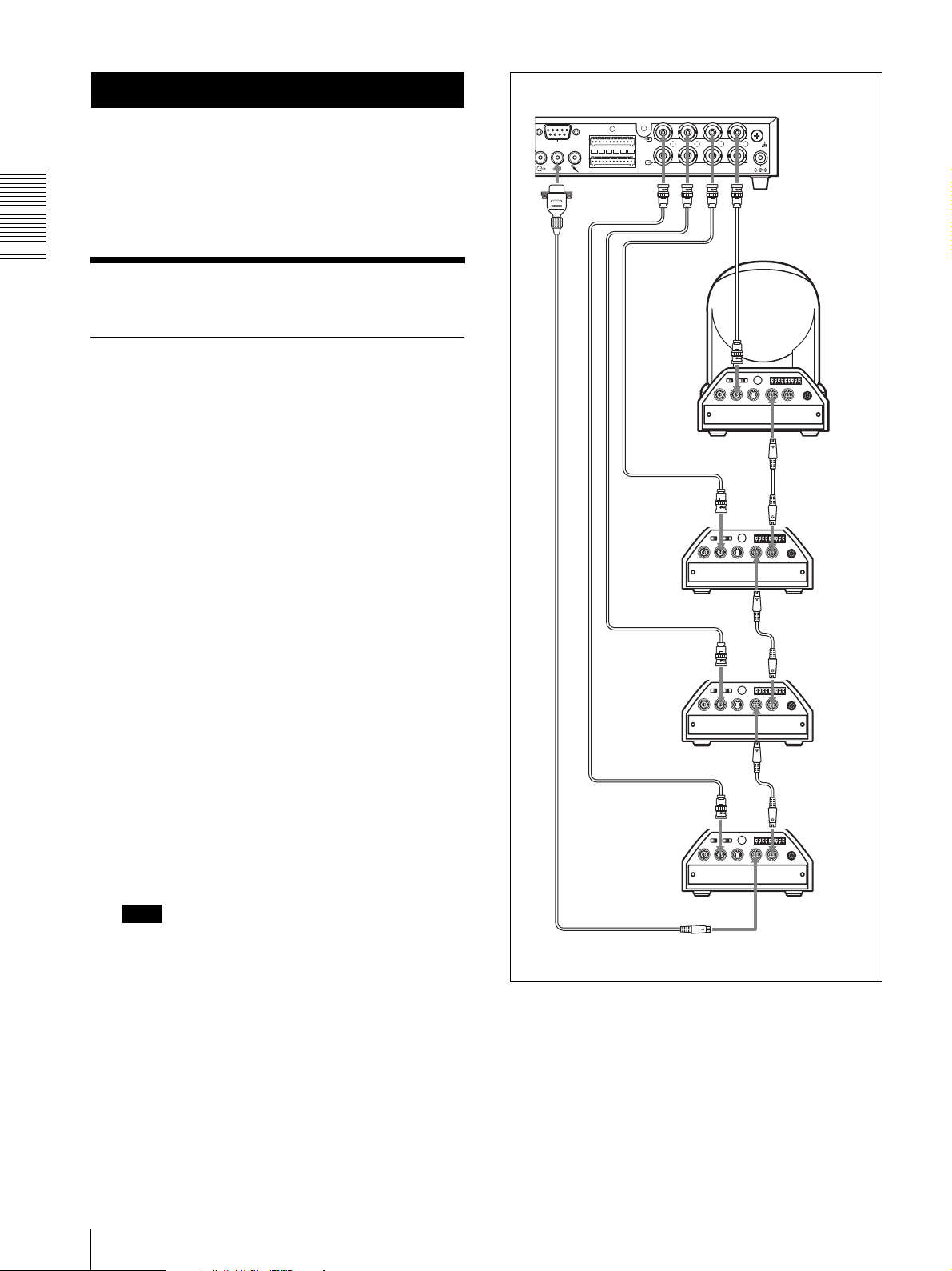
Connecting BRC-300, EVI-D100 and EVID70 series
Up to four cameras can be connected to SNT-V704 at
the same time.
1
Connect the t connector 1 to 4 of SNT-V704 and
the video output connector of each camera.
Note
When connecting cameras, connect from the t
connector 1 to 4 in order. If these are connected at
random, this unit may not work properly.
2
Connect VISCA RS-232C connectors of SNTV704 and each camera.
Refer also to the Instruction manuals of the camera
for connection of the camera.
BRC-300 series (rear)
BRC-300 series (rear)
VISCA cable
(not supplied)
8
Connecting the Unit
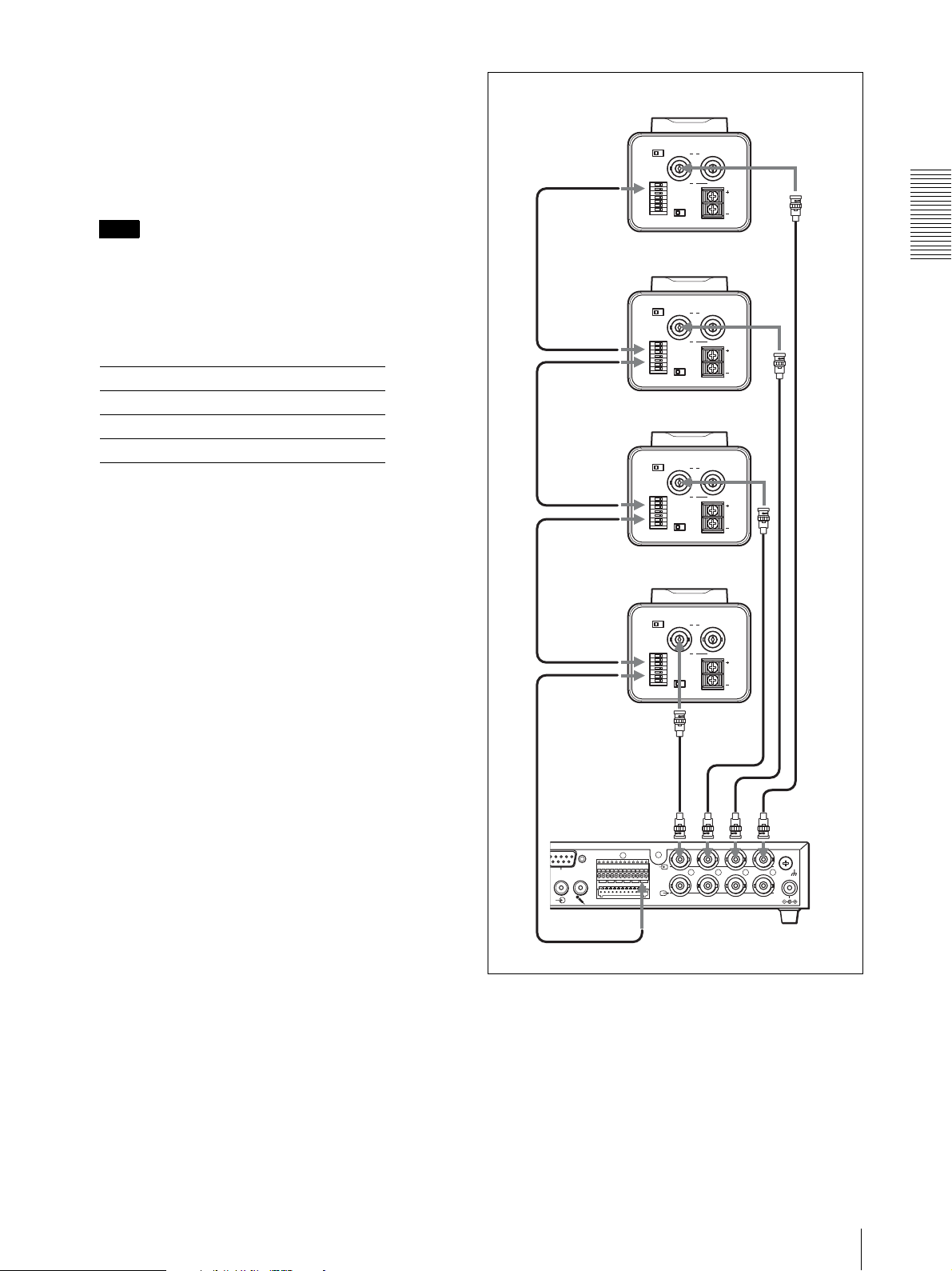
Connecting SSC-DC590/DC690 series
Up to four cameras can be connected to SNT-V704 at
the same time.
1
Connect the t 1 to 4 connectors of SNT-V704 and
the video output connector of each SSC-DC590/
DC690 series.
Note
When connecting cameras, connect from the t
connector 1 to 4 in order. If these are connected at
random, this unit may not work properly.
2
Connect the I/O port of SNT-V704 and the I/O port
of each SSC-DC590/DC690 series as follows:
SNT-V704 SSC-DC590/DC690
Pin 11 (+)/23 (+) Pin 1 (+)
Pin 12 (–)/24 (–) Pin 2 (–)
Pin 22 (GND) Pin 4 (COM)
For details on the I/O port, see “Pin Assignment and
Use of I/O Port” on page 69.
3
Set the ADDRESS switch of each SSC-DC590/
DC690 series as follows:
– When connecting to t 1 connector, set the
ADDRESS switch to “1”.
– When connecting to t 2 connector, set the
ADDRESS switch to “2”.
– When connecting to t 3 connector, set the
ADDRESS switch to “3”.
– When connecting to t 4 connector, set the
ADDRESS switch to “4”.
SSC-DC590/DC690 series (rear)
SEE INSTRUCTION MANUAL
MODE
DC IN/VS IN
AAB
VIDEO OUT
MONITOR OUT
1,2,4
I/O
B
VIDEO OUT
MENU LOCK
OFF ON
VS IN
1
2
3
4
5
6
7
SSC-DC590/DC690 series (rear)
SEE INSTRUCTION MANUAL
MODE
DC IN/VS IN
AAB
VIDEO OUT
MONITOR OUT
1,2,4
1,2,4
I/O
B
VIDEO OUT
MENU LOCK
OFF ON
VS IN
1
2
3
4
5
6
7
SSC-DC590/DC690 series (rear)
SEE INSTRUCTION MANUAL
MODE
DC IN/VS IN
AAB
VIDEO OUT
MONITOR OUT
I/O
B
VIDEO OUT
MENU LOCK
OFF ON
VS IN
1,2,4
1,2,4
1
2
3
4
5
6
7
SSC-DC590/DC690 series (rear)
SEE INSTRUCTION MANUAL
MODE
DC IN/VS IN
AAB
VIDEO OUT
MONITOR OUT
1,2,4
1,2,4
I/O
B
VIDEO OUT
MENU LOCK
OFF ON
VS IN
1
2
3
4
5
6
7
DC
12V
Preparation
DC
12V
DC
12V
DC
12V
Refer also to the Instruction manuals of the camera
for connection of the camera.
75-ohm coaxial
cable (not supplied)
112
RS-232C
I/O
13 24
10, 11, 12
1234
SEE INSTRUCTION MANUAL
CLASS 2 WIRING
SNT-V704 (rear)
DC 12V
Connecting the Unit
9
Preparation
Connecting to a Computer or a Network
To connect to the computer, use a commercially
available network cable (cross cable).
To connect to the network, use a commercially available
network cable (straight cable).
System Requirements
Processor
Intel Pentium 4, 2GHz or higher (Pentium 4, 3 GHz or
higher recommended)
RAM
256 MB or more (512 MB or more recommended)
OS
Microsoft Windows 2000/ XP/ Vista
Web browser
Microsoft Internet Explorer Ver. 5.5, Ver. 6.0 or Ver. 7.0
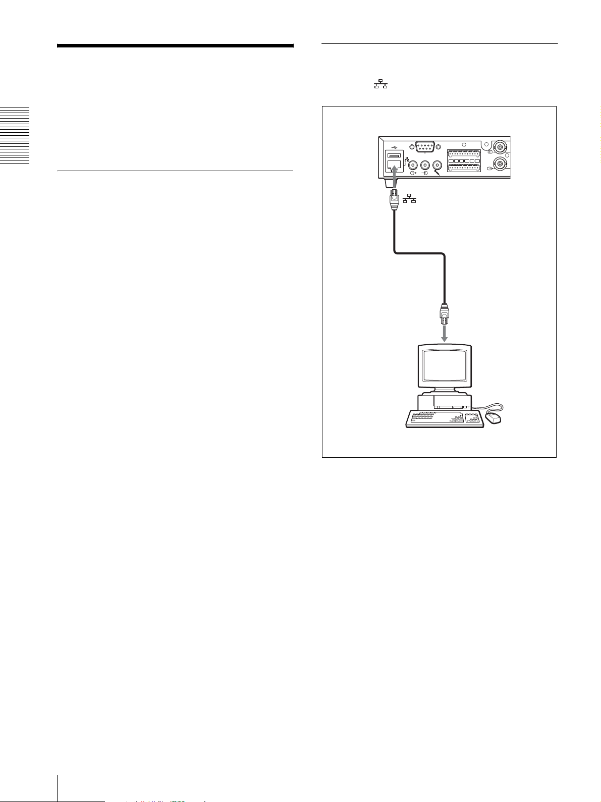
Connecting this Unit to a Computer
Using a commercially available network cable (cross),
connect the (network) port of this unit to the
network connector of a computer.
SNT-V704 (rear)
112
RS-232C
I/O
13 24
Network cable
(cross, not supplied)
Network connector
1
SEE INSTRUCTION
JAVA
Java Runtime Environment virsion 4.0 or later
It can be downloaded from the follwing URL
http://java.com
Computer
10
Connecting to a Computer or a Network
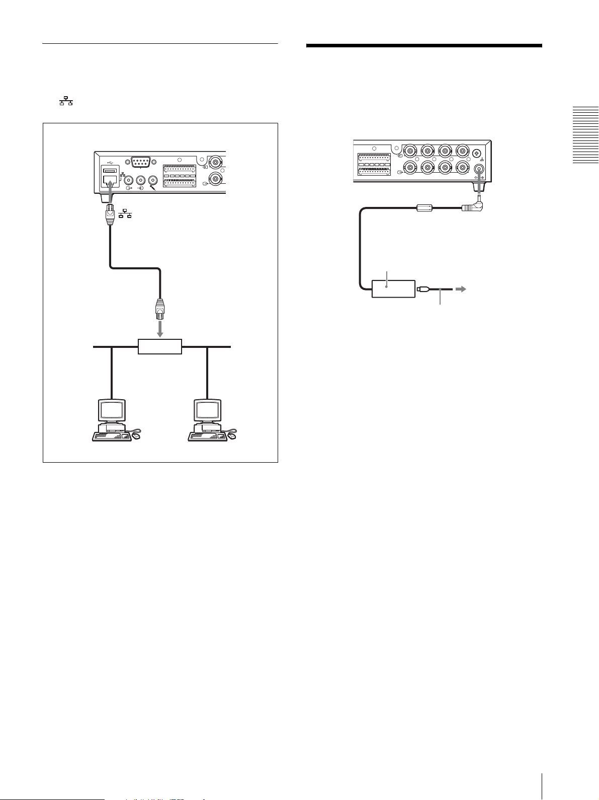
Connecting this Unit to a Local Network
Using a commercially available network cable, connect
the (network) port of this unit to a hub in the
network.
SNT-V704 (rear)
112
RS-232C
I/O
13 24
1
SEE INSTRUCTION
Connecting Power
Connect the supplied AC adaptor and the AC power cord
as illustrated below.
112
O
13 24
1234
SEE INSTRUCTION MANUAL
CLASS 2 WIRING
DC 12V
DC IN 12V
Preparation
Network cable
(straight, not supplied)
10BASE-T/
100BASE-TX
Hub
Network
AC adaptor
(supplied)
to the wall outlet
AC power code
Connecting Power
11
Preparation
Assigning the IP Address to the Unit
To connect this unit to a network, you need to assign a
new IP address to the unit.
You can assign an IP address in two ways:
• Using the setup program stored in the supplied CDROM (see this page)
• Using the ARP (Address Resolution Protocol)
commands (see page 65)
This section explains how to assign an IP address to the
camera using the supplied setup program and how to
configure the network.
Before starting, connect the unit to a local network,
referring to “Connecting to a Computer or a Network”
(see page 10).
Consult the administrator of the network about the
assigned IP address.
Note
set up correctly. Delete the downloaded file, and
click the Setup icon again.
4
Install the IP Setup Program on your computer
using the wizard.
If the Software License Agreement is displayed,
read it carefully and click Accept to continue with
the installation.
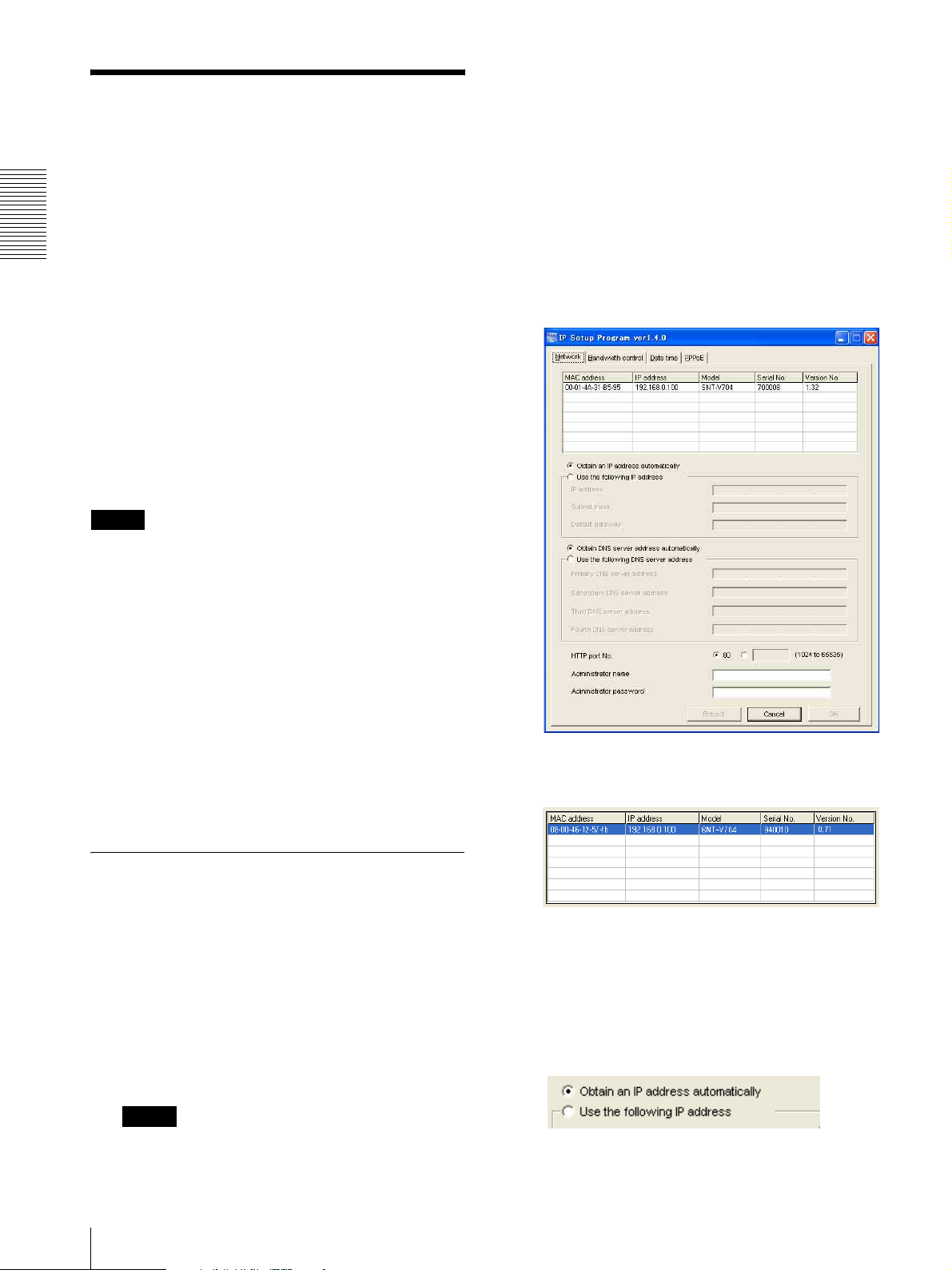
5
Start the IP Setup Program.
The program detects the video network station
SNT-V704 connected to the local network and lists
them on the Network tab window.
• The Setup Program may not operate correctly if you
use a personal firewall or antivirus software in your
computer. In that case, disable the software or assign
an IP address to the camera using another method. For
example, see “Assigning the IP Address to the Unit
Using ARP Commands” on page 65
• It you are using Windows XP Service Pack 2, disable
the Windows Firewall function. Otherwise the IP
Setup Program will not operate correctly.
To disable Windows Firewall, operate as follows:
1 Open Windows Firewall from Control Panel.
With the category display, you can find Windows
Firewall in Security Center.
2 Select Off, and click OK.
Assigning an IP address using the Setup Program
1
Insert the supplied CD-ROM disc into your CDROM drive.
After a short time a window will open displaying
the files on the CD-ROM.
2
Click the Setup icon of IP Setup Program.
The “File Download” dialog opens.
6
Click on the SNT-V704 you want to assign a new IP
address in the list.
The network settings for the selected SNT-V704 are
displayed.
7
Set the IP address.
To obtain the IP address automatically from a
DHCP server:
Select Obtain an IP address automatically.
3
Click Open.
Note
If you click “Save this program to disk” on the “File
Download” dialog, you will not be able to perform
12
Assigning the IP Address to the Unit
The IP address, Subnet mask and Default gateway
are assigned automatically.
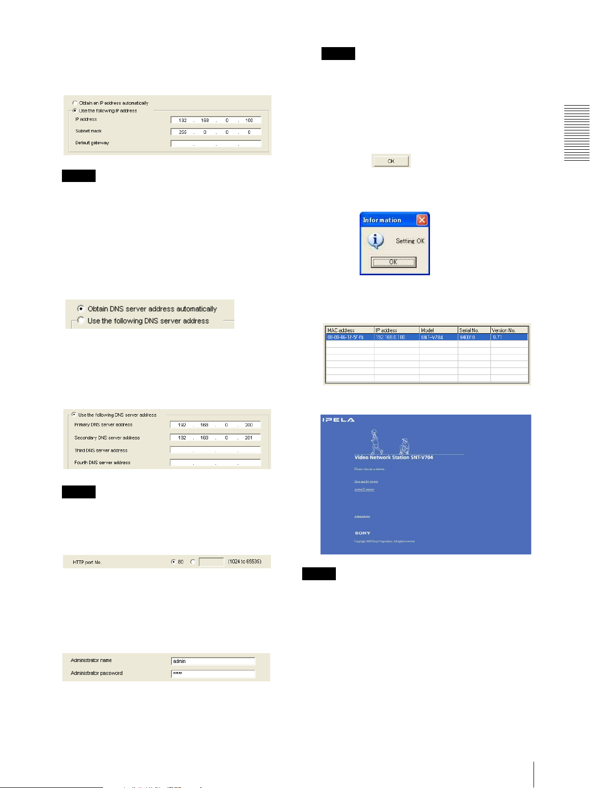
To specify the IP address manually:
Select Use the following IP address, and type the
IP address, Subnet mask and Default gateway in the
relevant boxes.
Note
You cannot change the Administrator name and
Administrator password in this step. To change
these items, see “Setting the User – User setting
Page” on page 39.
11
Confirm that all items are correctly set, then click
OK.
Note
When you select Obtain an IP address
automatically, make sure that the DHCP server is
operating on the network.
8
Set the DNS server address.
To obtain the DNS server addresses
automatically:
Select Obtain DNS server address automatically.
To specify the DNS server addresses manually:
Select Use the following DNS server address, and
type the Primary DNS server address and
Secondary DNS server address in the relevant
boxes.
If “Setting OK” is displayed, the IP address is
correctly assigned.
12
To access the unit directly, double-click the unit
name in the list.
The welcome page is displayed in the Web browser.
Preparation
Note
The Third DNS server address and Fourth DNS
server address are invalid for this camera.
9
Set the HTTP port No.
Normally, select 80 for the HTTP port No. To use
another port number, type the port number between
1024 and 65535 in the text box.
10
Type the Administrator name and Administrator
password.
The factory settings of both items are “admin.”
Note
If the IP address is not set correctly, the welcome page
does not appear after step 12. In that case, try to set the
IP address again.
Assigning the IP Address to the Unit
13
Accessing the Unit Using the Web Browser
After the IP address has been assigned to the unit, check
that you can actually access the camera using the Web
browser installed on your computer.
Use Internet Explorer as the Web browser.
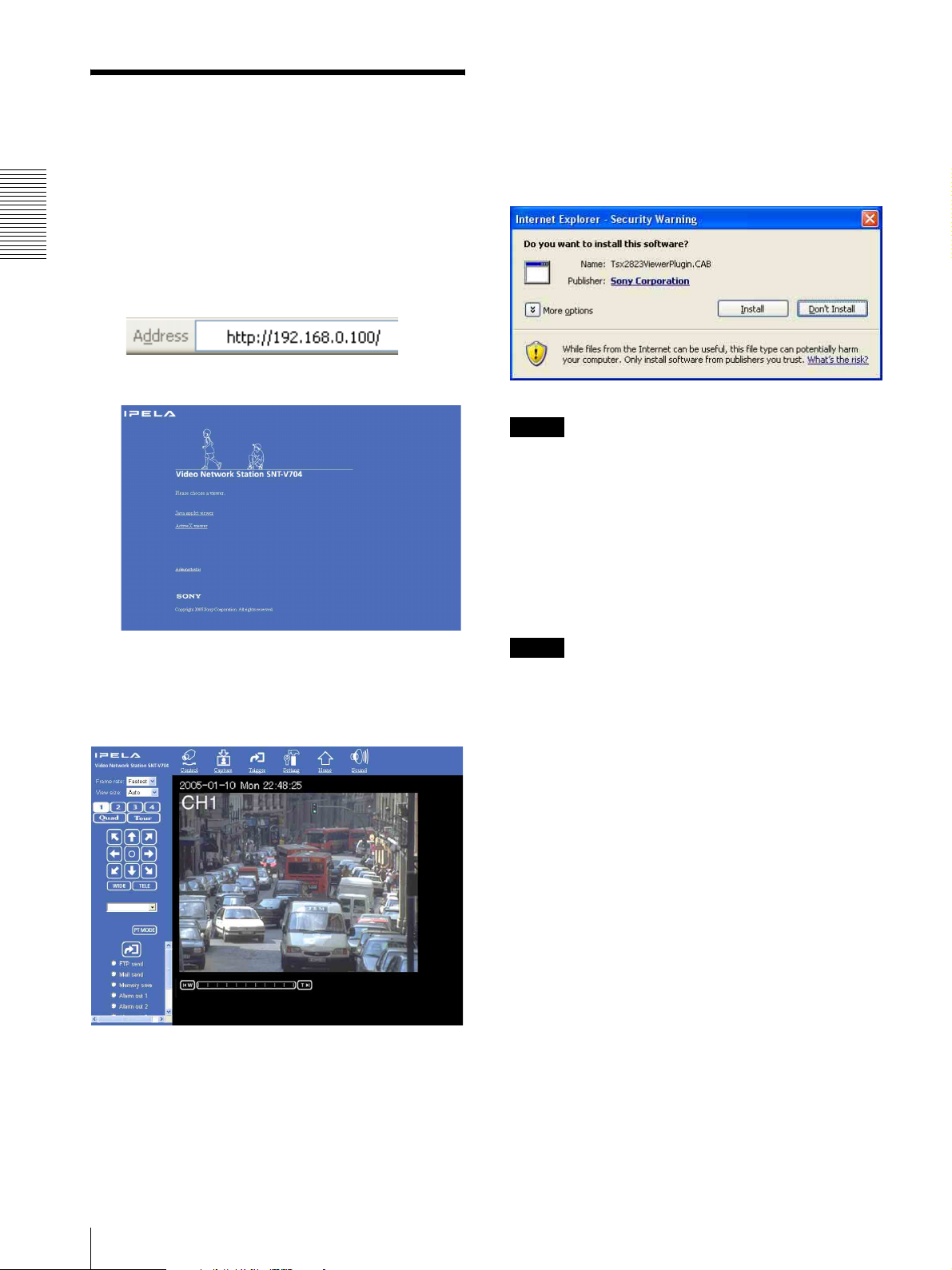
When the main viewer of the unit is
displayed for the first time
When you click Enter, “Security Warning” is displayed.
When you click Install, ActiveX control is installed and
the main viewer is displayed.
Preparation
1
Start the Web browser on the computer and type the
IP address of the unit in the URL box.
The welcome page is displayed.
2
Click ActiveX viewer.
The Main Viewer page is displayed and the monitor
image(s) from the camera(s) appear(s) on the
screen.
Notes
• If Automatic configuration is enabled in the Local
Area Network (LAN) Settings of Internet Explorer,
the image may not be displayed. In that case, disable
Automatic configuration and set the Proxy server
manually. For the setting of the Proxy server, consult
your network administrator.
• When you install ActiveX viewer on Windows 2000,
Windows XP or Windows Vista, you should be logged
in to the computer as Administrator.
Tip
Every page of this software is optimized as display
character size Medium for Internet Explorer.
To display the welcome page and the
main viewer correctly
To operate the welcome page and the main viewer
correctly, set the security level of the Internet Explorer
to Medium or lower, as follows:
If the main viewer is displayed correctly, accessing
the camera is confirmed.
14
Accessing the Unit Using the Web Browser
1
Select To ol s from the menu bar for Internet
Explorer, then select Internet Options and click
the Security tab.
2
Click the Internet icon (when using the camera via
the Internet) or Local intranet icon (when using
the camera via a local network).
3
Set the slider to Medium or lower. (If the slider is
not displayed, click Default Level.)

When using antivirus software, etc. on
the computer
• When you use antivirus software, security software,
personal firewall or pop-up blocker on your computer,
the camera performance may be reduced, for example,
the frame rate for displaying the image may be lower.
• The Web page displayed when you log in to the
camera uses JavaScript. The display of the Web page
may be affected if you use antivirus software or other
software described above on your computer.
Preparation
Accessing the Unit Using the Web Browser
15
Operating the SNT-V704
2
Click the Internet icon (when using this unit via
the Internet) or Local intranet icon (when using
this unit via a local network).
Operating the SNT-V704
This section explains how to monitor the images from
the cameras using the Web browser. For setting this unit,
see “Administrating the SNT-V704” on page 26.
Logging in to Homepage
— Welcome Page
Logging in as a User
1
Start the web browser on the computer and type the
IP address of this unit.
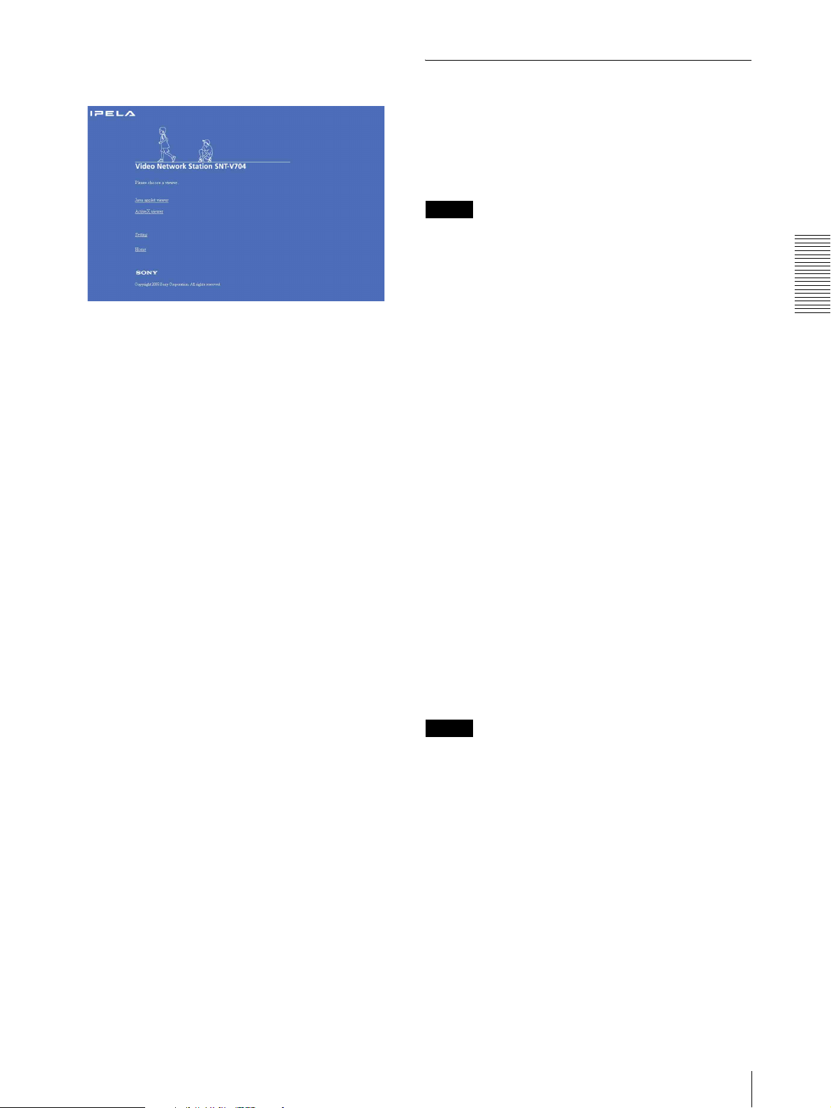
The welcome page of Video Network Station
SNT-V704 is displayed.
3
Set the slider to Medium or lower. (If the slider is
not displayed, click Default Level.)
When using antivirus software in the
computer
• When you use antivirus software in your computer, the
performance of this unit may be reduced, for example,
the frame rate for displaying the image may lower.
• The Web page displayed when you log in this unit uses
Java Script. The display of the page may be affected
if you use antivirus software in your computer.
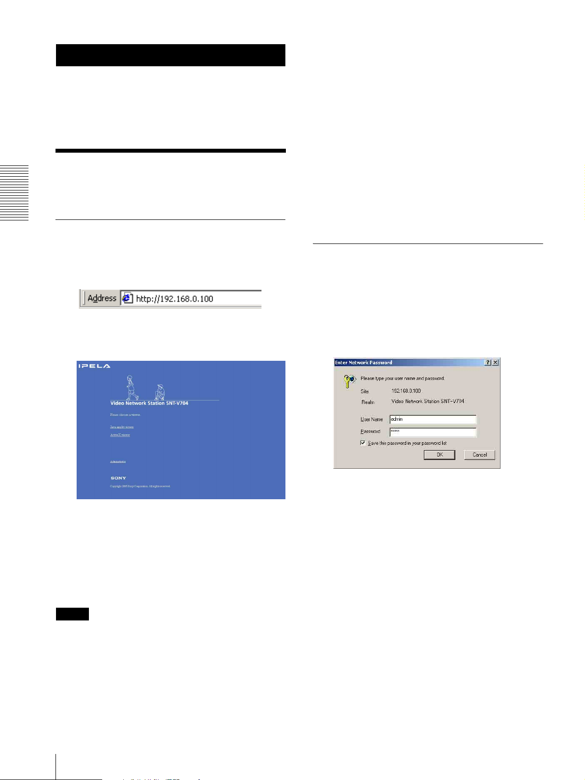
Logging in as Administrator
If you log in this unit as the Administrator, you can
perform all the settings provided with the software. The
Administrator may be logged in at any time, regardless
of the number of the users being accessed.
1
Click Administrator on the welcome page.
The login page appears.
2
Click to select the viewer.
You can select the viewer from among Java applet
viewer and ActiveX viewer, whichever is suitable
for your system environments and usage.
For details, see “About Viewers” on page 17.
When you have selected the viewer, the main
viewer page appears (see page 18).
Note
To operate the welcome page correctly, set the security
level of the Internet Explorer to Medium or lower, as
follows:
1
Select To ol from the menu bar of Internet Explorer,
then select Internet Options and Security tab in
sequence.
16
Logging in to Homepage — Welcome Page
2
Enter the user name and password for
Administrator, then click OK.
The user name “admin” and the password “admin”
are set at the factory for the Administrator. You can
change them on the User setting page in the
Administrator menu (see page 39).
The welcome page is changed to that for
Administrator.
3
Select the viewer.
You can select the viewer from among Java applet
viewer and ActiveX viewer, whichever is suitable
for your system environments and usage.
For details, see “About Viewers” on page 17.
When you have selected the viewer, the main
viewer page appears (see page 18).
Other functions on the welcome page for
Administrator
Setting
Click to display the Administrator menu (see page 26).
Home
Click to return to the normal welcome page.
About Viewers
You can select the following two viewers, both of which
are operable on Internet Explorer.
Java applet viewer
It displays the main viewer page using Java.
Notes
• When you have set Video mode (page 36) to JPEG to
display an image, it is not displayed if another user
changes Video mode to MPEG4.
• The frame rate is lower than that for the ActiveX
viewer.
• You cannot use the audio function.
• If the viewer does not operate correctly, install or
activate Java as follows:
Select Tool from the menu bar of Internet Explorer,
then select Internet Option and the Advanced tab in
sequence, and check JIT compiler for virtual
machine enabled (requires restart). Then restart
Internet Explorer.
•When JIT compiler for virtual machine enable
(requires restart) cannot be displayed, download the
correct version of SUN JAVA and install it.
JAVA
Java Runtime Environment virsion 4.0 or later
It can be downloaded from the follwing URL
http://java.com
ActiveX viewer
It displays the main viewer page using ActiveX.
With this viewer, you can display images at a high frame
rate.
When you log in this unit using Internet Explorer for the
first time, the Security Warning appears. Click Ye s and
install ActiveX Control.
Operating the SNT-V704
Notes
• If Automatic configuration is enabled in the Local
Area Network (LAN) Settings on Internet Explorer,
the image may not be displayed. In this case, disable
Automatic configuration and set the Proxy server
manually. For setting the Proxy server, consult your
network administrator.
• When you install ActiveX viewer, you should have
logged in the computer as the Administrator.
• If you run other software on the personal computer
while displaying the viewer, an increase of the CPU
load may cause the image of the viewer to stop. In this
case, click the Updating icon of Internet Explorer. The
normal image will recover.
Logging in to Homepage — Welcome Page
17
Operating the SNT-V704
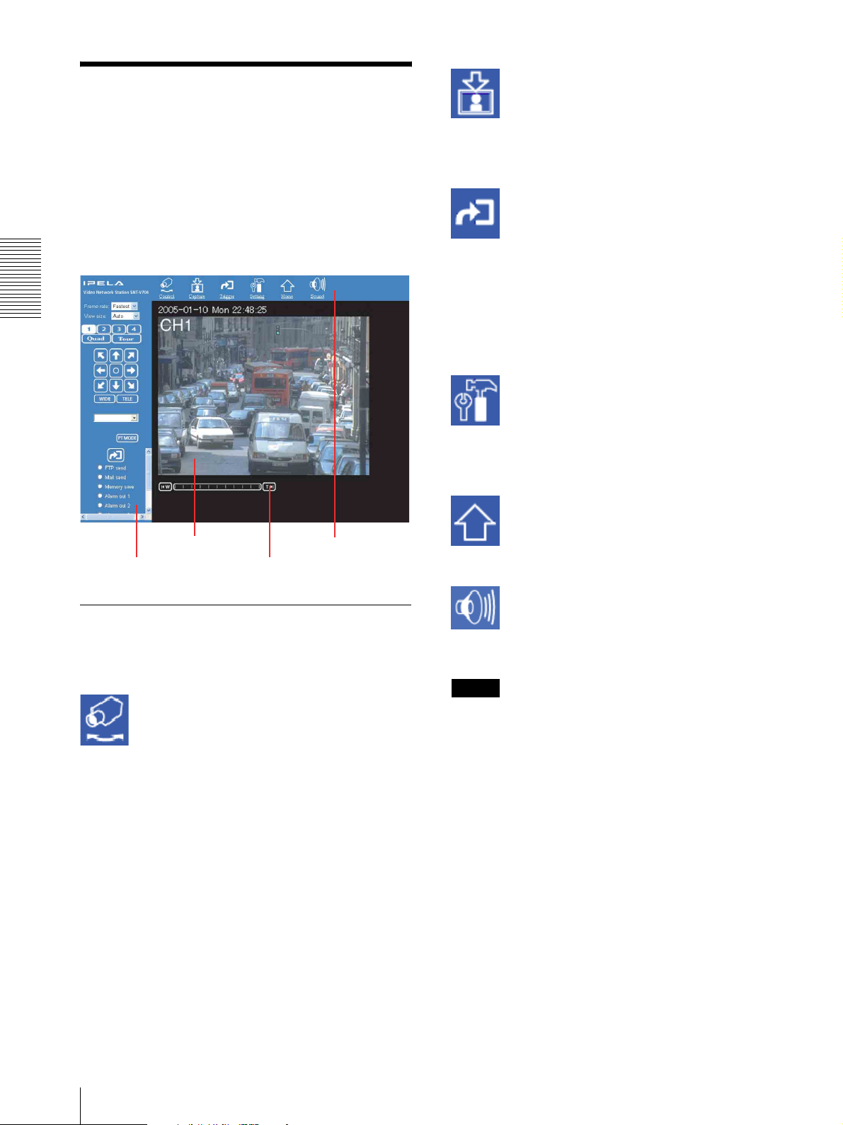
Configuration of Main Viewer Page
When you select the viewer, the main viewer page is
displayed.
This section briefly explains the functions of the parts
and controls on the main viewer page. For a detailed
explanation on each part or control, see the specified
pages.
Main viewer page
Capture
Captures a still image shot by the camera and stores it in
the computer. (See “Capturing a Monitor Image” on
page 25.)
Trigg er
Displays the trigger control parts on the image control
section.
By clicking the trigger button, you can control various
applications manually. (See “Controlling the
Application Manually” on page 24.)
User access right Level 3 or Level 4 is required for this
function.
Setting
Displays the Administrator menu. (See “Configuration
of Administrator Menu Page” on page 26.)
User access right Level 4 is required for this function.
Menu section
Image control
section
Monitor
image
section
zoom bar
Menu Section
The available functions are limited by user access right.
You can change user access right on the User setting
page (see page 39).
Control
Displays the camera control parts on the image control
section. (See “Operating the Camera from the Image
Control Section (BRC-300, EVI-D100, EVI-D70, and
cameras not manufactured by Sony only)” on page 21.)
Also enables the panning, tilting and zooming
operations from the monitor image. (See “Operating the
Camera from the Monitor Image (Only when the BRC300, the EVI-D100 or the EVI-D70 is connected with
VISCA cable)” on page 23.)
User access right Level 2 to Level 4 is required for this
function.
Home
Displays the Welcome page.
Sound
Enables momentary cutting off the sound from a
computer.
Note
The Sound icon is not displayed because the audio
function cannot be used in Java applet viewer.
18
Configuration of Main Viewer Page
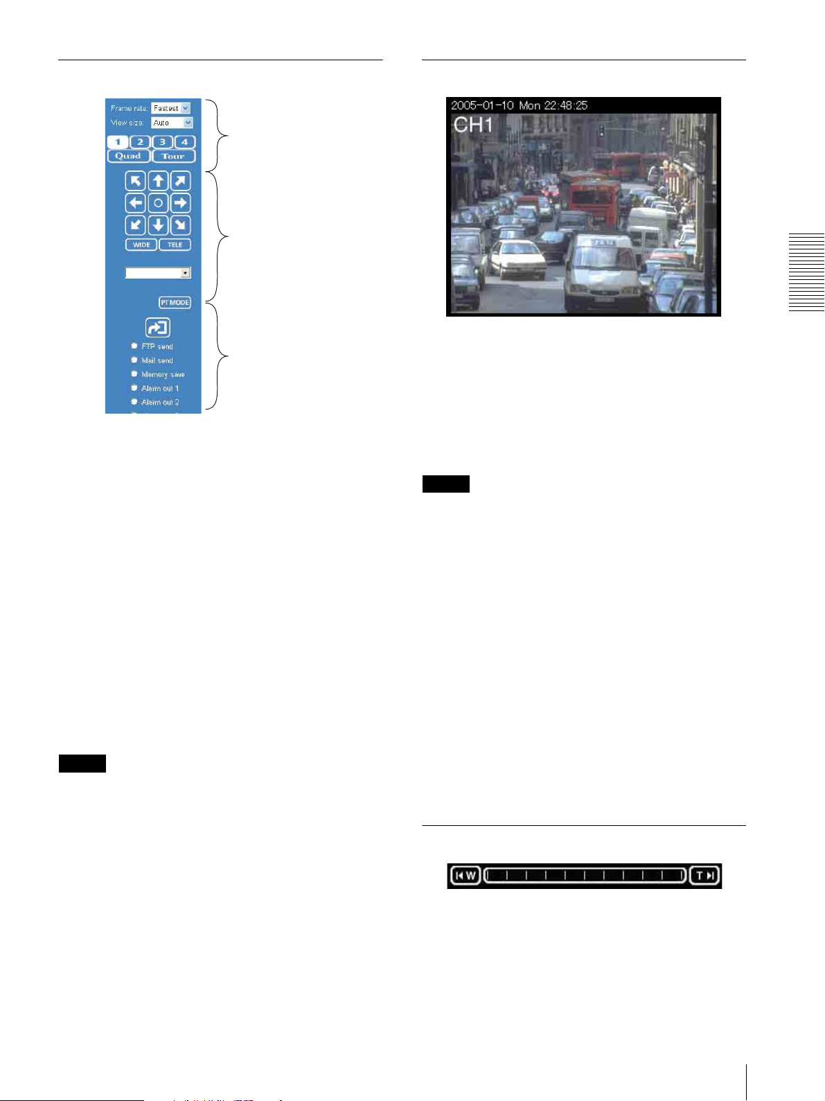
Image Control Section
Monitor image display parts
Camera control parts
Trigger control parts
Monitor image display parts
You can select the image you want to monitor when two
or more cameras are connected to this unit. See
“Displaying the Monitor Images” on page 20.
Camera control parts
These parts are displayed when you click Control on the
menu section. You can operate the camera using these
parts.
See “Operating the Camera from the Image Control
Section (BRC-300, EVI-D100, EVI-D70, and cameras
not manufactured by Sony only)” on page 21.
Trigger control parts
These parts are displayed when you click Trigger on the
menu section. You can output a trigger using these parts.
See “Controlling the Application Manually” on page 24.
Notes
• The camera control parts and the trigger control parts
display different contents due to the connected
camera. They display the features only the camera is
equipped with.
• If the image control section does not work normally,
install or activate Java. For details, see “Java applet
viewer” on page 17.
Monitor Image Section
Operating the SNT-V704
The image shot by the camera connected to this unit is
shown here.
Click Control on the menu section to allow panning,
tilting and zooming of the camera from the monitor
image.
See “Operating the Camera from the Monitor Image
(Only when the BRC-300, the EVI-D100 or the EVID70 is connected with VISCA cable)” on page 23.
Notes
• When cables are connected to Video out 1 to 4
connectors (BNC type), the 75 ohms terminal is
automatically turned to off inside the camera. This is
why the video image turns whitish if 75 ohms is not
terminated in the connected equipment. This is not a
malfunction of the camera. When connecting to the
video out terminals, be sure to terminate 75 ohms in
the connected equipment.
• This camera receives the video signal in 720 × 480
(NTSC)/720 × 576 (PAL) format. Some cameras
output the video signal in a smaller size than 720 × 480
(NTSC)/720 × 576 (PAL). In this case, the image in
the monitor image section has a black border.
If you operate Pan, Tilt, or Zoom on with this image,
the black area is also affected. (See “Operating the
Camera from the Monitor Image (Only when the
BRC-300, the EVI-D100 or the EVI-D70 is connected
with VISCA cable)” on page 23.)
Zoom Bar
The zoom bar is displayed when you click Control on
the menu section. You can operate the optical zoom
using the zoom bar.
See “Zooming Using the Zoom Bar” on page 23.
Configuration of Main Viewer Page
19
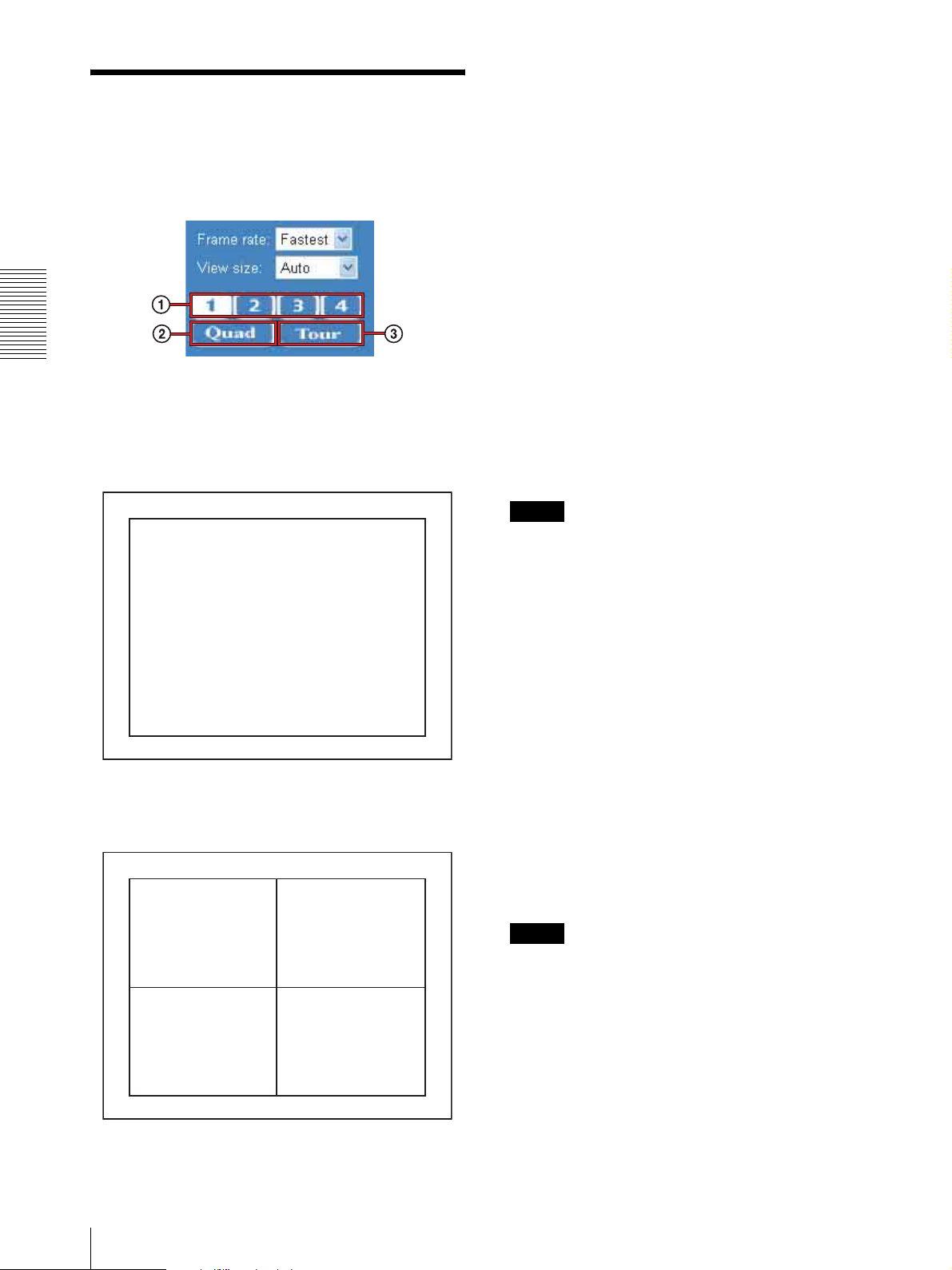
Displaying the Monitor Images
3 When Tour is selected, the image is displayed
according to the preset Tour operation of a
camera. For details on the Tour operation, see
page 43.
Operating the SNT-V704
You can display the monitor image from the image
control section on the main viewer page.
Selecting the image you want to monitor
1 Press one of the numeric buttons on the upper
line to select a channel and the image of the
selected channel is displayed.
2005-05-17 Thu 11:57:28
CH1
Selecting the frame rate (JPEG mode
only)
Click the down-arrow button in the Frame rate box and
select the frame rate with which the images are
transmitted, from the drop-down list.
You can select the frame rate from among the following:
For the NTSC cameras:
1, 2, 3, 4, 5, 6, 8, 10, 15, 20, 25, Fastest
For the PAL cameras:
1, 2, 3, 4, 5, 6, 8, 12, 16, 20, Fastest
The numbers indicate “FPS” (the number of frames
transmitted per second).
With Fastest, the camera transmits the maximum
number of frames possible for the connected line. The
maximum frame rate is 30 FPS (NTSC) or 25 FPS
(PAL).
Notes
• When the monitor image is set to Quad or the output
format of the camera image is set to MPEG4
(page 36), the Frame rate box is not displayed.
• The frame rate options indicate the maximum number
of frames that can be transmitted. The number of
frames actually transmitted may vary depending on
the network environments and camera settings (image
size and image quality settings).
2 By selecting QUAD, the monitor screen is
divided into four parts, and the images of four
cameras can be displayed at the same time.
2005-05-17 Thu 11:57:28
CH1 CH2
CH3 CH4
Selecting the view size
Click the down-arrow button in the View size box and
select the view size from the drop-down list.
You can select the view size from among the following.
For the NTSC camera:
Auto, 720 × 480, 640 × 480, 320 × 240
For the PAL camera:
Auto, 720 × 576, 640 × 480, 320 × 240
Auto is determined by the image size specified with
Image size on the Video setting page (see page 35).
Notes
• When the monitor image is set to Quad, the View size
box is not displayed.
• When you select a larger size than the one selected in
Image size in the Video setting (page 35), the image is
zoomed but the resolution is not increased.
• An image is zoomed or reduced while the horizontal
to vertical ratio is fixed. This is why an image may be
displayed in a size smaller than the one selected.
20
Displaying the Monitor Images
Operating the Camera
from the Image Control
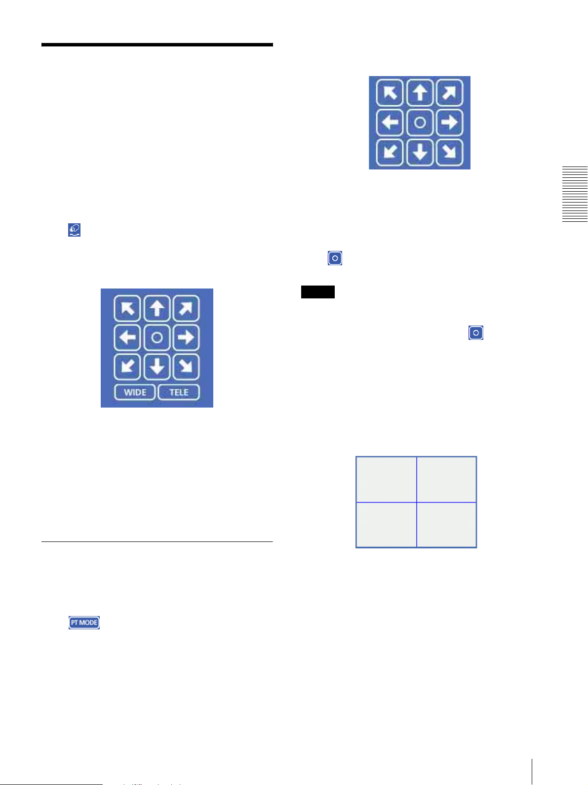
Panning and tilting using the 8-direction
arrow buttons
Section
(BRC-300, EVI-D100,
EVI-D70, and cameras not
manufactured by Sony only)
You can operate the camera connecting to this unit from
the image control section on the main viewer page.
For this function, user access right Level 2 to Level 4 is
required (see page 39).
Click Control on the menu section to display the
camera control parts.
Image control section (camera control parts)
Selecting the Camera You Want to
Control
First, press one of the numeric buttons 1 to 4 of the
monitor image display parts to select the image of the
camera you want to control (BRC-300, EVI-D100 or
EVI-D70 only). When QUAD is selected, the monitor
image cannot be controlled with the image control
section.
Observe the monitor image and click the arrow button
indicating the direction in which you want to move the
camera. The camera moves and the monitor image
follows.
Hold down the arrow button to move the direction of the
camera continuously.
Click to return the camera to the factory-preset
default position.
Notes
• If the Exclusive control mode menu on the System
setting page is set to On (see page 28), the remaining
operation time is displayed instead of .
• You can change the operation mode of the panning and
tilting using the 8-direction arrow buttons from the
Camera control mode setting section on the Camera
setting page (see page 33). When you have changed
the operation mode, click Control on the menu
section to update the operation mode setting on the
image control section.
Panning and tilting using the tablet
Operating the SNT-V704
Panning and Tilting
You can pan and tilt the camera using the 8-direction
arrow buttons or the tablet.
Setting the pan/tilt mode
Click . Each click alternates the 8-direction
arrow mode and the tablet mode.
Operating the Camera from the Image Control Section (BRC-300, EVI-D100, EVI-D70, and cameras not manufactured by Sony only)
When you click PT MODE, the 8-direction arrow
buttons change to a tablet. The tablet represents the
monitor image.
A click on the tablet moves the direction of the camera
so that the clicked position goes to the center of the
monitor image.
If you want to change the direction of the camera further,
click on the tablet and drag in the direction in which you
want to move the camera. The direction of the camera
moves as you drag. Hold down the button to move the
direction of the camera continuously.
21
Operating the SNT-V704
Notes
• The tablet represents the whole monitor image even
when you have trimmed the monitor image using the
Area setting menu on the Video setting page (see
page 35).
• If the Exclusive control mode menu on the System
setting page is set to On (see page 28), the remaining
operation time is displayed on the lower right corner
of the tablet.
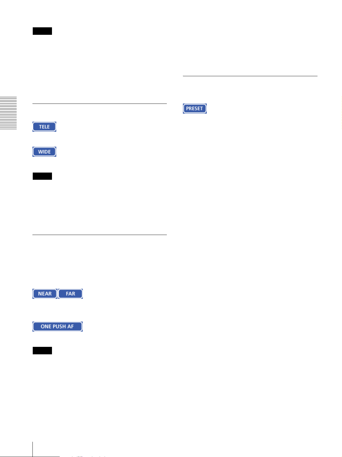
Zooming
CIick to zoom in.
Click to zoom out.
Note
You can change the operation mode of the zooming
using the TELE/WIDE buttons from the Camera control
mode setting section on the Camera setting page (see
page 33). When you have changed the operation mode,
click Control on the menu section to update the
operation mode setting on the image control section.
section to update the operation mode setting on the
image control section.
• If the NEAR, FAR and ONE PUSH AF buttons are not
displayed, click the FOCUS button on the image
control section. The three buttons appear and the
FOCUS button name changes to PRESET.
Moving the Camera to the Preset Position
When you click this button, the PRESET list box
appears.
The PRESET button name changes to FOCUS.
PRESET list box
Click the down-arrow button and select the preset
position name from the drop-down list. Then, the
camera will move to the preset position that you have
stored in memory using the Preset position setting page
(see page 41).
Focusing
The focus is automatically adjusted when the Focus
mode menu on the Camera setting page is set to Auto
(see page 31). When you set it to Manual, you can
adjust the focus manually from the image control
section, or adjust it with a push of the button.
Adjust the focus manually by clicking the two buttons
alternately.
Click this button to adjust the focus instantly.
Notes
• When you have changed the Focus mode menu on the
Camera setting page, click the Control button on the
menu section to update the focus mode setting on the
image control section.
• You can change the operation mode of the manual
focusing using the NEAR/FAR buttons from the
Camera control mode setting section on the Camera
setting page (see page 33). When you have changed
the operation mode, click Control on the menu
22
Operating the Camera from the Image Control Section (BRC-300, EVI-D100, EVI-D70, and cameras not manufactured by Sony only)
 Loading...