

Sony SNT-EX101E, Ipela SNT-EX101, Ipela SNT-EX104, Ipela SNT-EP104, Ipela SNT-EX154 User Manual
...
4-154-542-11 (1)
Video Network Station
User’s Guide
Software Version 1.0
Before operating the unit, please read this manual thoroughly
and retain it for future reference.
SNT-EX101
SNT-EX104/SNT-EP104
SNT-EX154/SNT-EP154
SNT-RS1U/SNT-RS3U
© 2009 Sony Corporation

Table of Contents
Overview
Features .................................................................. 4
How to Use This User’s Guide .............................. 5
System Requirements ............................................ 5
Preparation
Assigning the IP Address to the unit ................... 6
Assigning an IP address using SNC toolbox ..... 6
When using Windows XP Service Pack 2 or
later ................................................................... 8
When using Windows Vista ............................. 10
Accessing the System Using the Web
Browser ................................................................. 13
Basic Configuration by the Administrator ....... 15
Operating the unit
Administrator and User ...................................... 16
Logging in to System ........................................... 17
Logging in as a user ......................................... 17
About Viewers .................................................. 17
Configuration of Main Viewer ........................... 18
Main menu ....................................................... 18
Control panel section ....................................... 18
Monitor image .................................................. 20
Plug-in free Viewer .......................................... 20
Operating the Camera ........................................ 21
Controlling via the control panel ..................... 21
Moving the camera to a preset position ........... 22
Using the Trigger Button ................................... 22
Sending a monitor image via e-mail ................ 22
Sending a monitor image to an FTP server ...... 22
Recording a camera image as a still image ...... 22
Controlling alarm output .................................. 23
Playing an audio file stored in the system ........ 23
Switching TCP/UDP Transmission Mode ......... 23
Using the System Utility ...................................... 24
SNC Viewer ..................................................... 24
SNC Desktop Viewer ....................................... 26
Administrating the unit
Basic Operations of the Administrator Menu ...27
How to set up the Administrator menu .............27
Configuration of the Administrator menu ........28
Configuring the System — System Menu ..........29
System Tab ........................................................29
Date & time Tab ................................................30
Superimpose Tab ..............................................31
Initialize Tab .....................................................32
System log Tab .................................................33
Access log Tab ..................................................33
Setting the Camera Image and Audio
— Camera Menu ..................................................34
Common Tab ....................................................34
Picture Tab ........................................................35
Privacy Masking tab .........................................35
Video codec Tab ...............................................36
Streaming Tab ...................................................37
Configuring the Network — Network Menu .....38
Network Tab .....................................................38
QoS Tab ............................................................39
Dynamic IP address notification Tab — Notifying
the IP Address .................................................40
Setting the SSL function — SSL Menu ..............42
SSL tab .............................................................42
CA certificate tab — Adding the CA certificate for
client authentication ........................................44
How to install the CA certificate ......................45
To remove an installed CA certificate ..............46
Using the 802.1X Authentication Function
— 802.1X Menu ....................................................47
System configuration of 802.1X network ........47
Common Tab – Basic setting of 802.1X
authentication function ...................................47
Client certificate Tab .........................................48
CA certificate Tab .............................................49
Setting the 802.1X authentication function
– Example of Windows Server 2003 ..............50
Setting the User — User Menu ...........................53
Setting the Security — Security Menu ...............54
Saving the Camera Position and Action — Preset
position Menu .......................................................54
Position Tab — Saving pan/tilt/zoom
position ...........................................................54
Position Tour Tab — Setting a position tour ....56
2
Table of Contents

Sending an Image via E-mail — e-Mail (SMTP)
Menu ..................................................................... 57
Common Tab — Setting the e-Mail (SMTP)
Function .......................................................... 57
Alarm sending Tab — Setting the e-mail sending
mode when detecting the alarm ...................... 58
Periodical sending Tab — Setting the periodical
e-mail sending mode ......................................59
Sending Images to FTP Server — FTP client
Menu ..................................................................... 60
Common Tab — Setting the FTP client
function .......................................................... 60
Alarm sending Tab — Setting the FTP client
action when detecting the alarm ..................... 61
Periodical sending Tab — Setting the periodical
FTP client activity .......................................... 62
Recording Images in Memory — Image memory
Menu ..................................................................... 63
Common Tab — Setting the image memory
function .......................................................... 63
Alarm recording Tab — Setting the Image
memory function when detecting the
alarm ............................................................... 64
Periodical recording Tab — Setting the periodical
recording mode ............................................... 65
Folder structure of image memory ................... 66
Downloading Images from the system — FTP
server Menu .........................................................67
Setting the Alarm Output — Alarm output
Menu ..................................................................... 67
Alarm output Tab .............................................. 67
Outputting Audio Linked to Alarm Detection
— Voice alert Menu ............................................. 69
Voice alert 1, 2, 3 Tab ....................................... 69
Setting the Operations from the Viewer
— Trigger Menu ..................................................70
Setting the Schedule — Schedule Menu ............ 72
Setting the Alarm Buffer — Alarm buffer
Menu ..................................................................... 73
Setting the Motion Detection/VMF Function
— Motion detection Menu .................................. 73
What are VMF functions-Video Motion
Filter ............................................................... 73
Setting items for motion detection ................... 74
VMF setting items ............................................ 76
Simple motion detection function .................... 79
Transmitting with External Equipment
— PTZ control I/F Menu .................................... 80
Configuring the Viewer — Viewer Menu .......... 81
Layout tab .........................................................81
HTML output tab ............................................. 83
Others
Using the Supplied SNC toolbox .........................84
Starting SNC toolbox ........................................84
How to use SNC toolbox ..................................84
Registering in My device ..................................86
Changing the Device list display method .........87
Setting SNC toolbox options ............................88
Using Privacy Masking — Masking
a Camera Image ..............................................89
Using the Custom Homepage ...........................90
Using the Firmware Upgrade ............................91
Using the Schedule Task ...................................91
Configuring the device setting ..........................93
Device restart and initialization ........................94
Using the SNC audio upload tool — Transmitting
Audio to unit .........................................................95
Installing the SNC audio upload tool ................95
Connecting the unit to the Computer ................95
Using the SNC audio upload tool .....................96
Using the SNC video player — Playing a Video/
Audio File Recorded with the unit ....................100
Installing the SNC video player ......................100
Using the SNC video player ...........................101
Assigning the IP Address to the unit using ARP
Commands ..........................................................102
Using the SNMP .................................................102
1. Inquiry Commands ....................................102
2. Setting Commands .....................................103
Glossary ..............................................................104
Index ....................................................................107
Table of Contents
3

Overview
Overview
Features
NOTICE TO USERS
© 2009 Sony Corporation. All rights reserved. This
manual or the software described herein, in whole or in
part, may not be reproduced, translated or reduced to
any machine readable form without prior written
approval from Sony Corporation.
• High-quality live images from camera can be
monitored at a maximum frame rate of 30 fps.
• XDNR and Visibility Enhancer enable clearer images
for streaming.
• Three video compression modes (video codecs)
JPEG/MPEG4/H.264 are supported.
• Single codec mode and dual codec modes are
available.
• The motion detection function is provided on the
SNT-EX101, SNT-EX104 and SNT-EX154. The
simple motion detection function is provided on the
SNT-EP104 and SNT-EP154. The camera tampering
detection alarm function is provided on the
SNT-EX101, SNT-EX104 and SNT-EX154.
• Up to 10 users can view images from one camera at
the same time.
• Date/time can be superimposed on the image.
SONY CORPORATION PROVIDES NO
WARRANTY WITH REGARD TO THIS MANUAL,
THE SOFTWARE OR OTHER INFORMATION
CONTAINED HEREIN AND HEREBY EXPRESSLY
DISCLAIMS ANY IMPLIED WARRANTIES OF
MERCHANTABILITY OR FITNESS FOR ANY
PARTICULAR PURPOSE WITH REGARD TO THIS
MANUAL, THE SOFTWARE OR SUCH OTHER
INFORMATION. IN NO EVENT SHALL SONY
CORPORATION BE LIABLE FOR ANY
INCIDENTAL, CONSEQUENTIAL OR SPECIAL
DAMAGES, WHETHER BASED ON TORT,
CONTRACT, OR OTHERWISE, ARISING OUT OF
OR IN CONNECTION WITH THIS MANUAL, THE
SOFTWARE OR OTHER INFORMATION
CONTAINED HEREIN OR THE USE THEREOF.
Sony Corporation reserves the right to make any
modification to this manual or the information
contained herein at any time without notice.
The software described herein may also be governed by
the terms of a separate user license agreement.
• “IPELA” and are trademarks of
Sony Corporation.
• Microsoft, Windows and Internet Explorer are
registered trademarks of Microsoft Corporation in
the United States and/or other countries.
• Java is a trademark of Sun Microsystems, Inc. in the
United States and other countries.
• Intel and Pentium are registered trademarks of Intel
Corporation or its subsidiaries in the United States
and other countries.
• Adobe, Adobe Reader and Adobe Flash are
trademarks of Adobe Systems Incorporated in the
United States and/or other countries.
All other company and product names are trademarks
or registered trademarks of the respective companies or
their respective makers.
4
Features

How to Use This User’s
System Requirements
Guide
This User’s Guide explains how to operate the video
network station from a computer.
The User’s Guide is designed to be read on the computer
display.
This section gives tips on making the most of the User’s
Guide-read it before you operate the camera.
Jumping to a related page
When you read the User’s Guide on the computer
display, you can click on a sentence to jump to a related
page.
Software display examples
Note that the displays shown in the User’s Guide are
explanatory examples. Some displays may be different
from the ones that appear in actual use.
The illustrations of the camera and menu display in the
User’s Guide show the SNC-RH124, SNC-RH164 or
SNT-EX104 video network station as an example.
Printing the User’s Guide
Depending on your system, certain displays or
illustrations in the User’s Guide, when printed out, may
differ from those that appear on your screen.
The following computer environment is necessary for
the computer to display images and the controls of the
camera.
(August 2009)
CPU
Intel Core 2 Duo, 1.8 GHz or higher.
Memory
1 GB or more.
OS
Microsoft Windows XP, Windows Vista
Web Browser
Microsoft Internet Explorer Ver 6.0 or 7.0
Display
1280 × 1024 pixels or higher.
Overview
Installation Manual (printed matter)
The supplied Installation Manual describes the names
and functions of parts and controls of the video network
station, connection examples, and how to set up the
camera. Be sure to read the Installation Manual before
hand.
How to Use This User’s Guide
5

Preparation
Assigning an IP address using SNC toolbox
Preparation
The Preparation section explains what the administrator
has to prepare for monitoring images after installation
and connection of the unit.
Assigning the IP Address to the unit
To connect the unit to a network, you need to assign a
new IP address to the unit when you install it for the first
time.
You can assign an IP address in two ways:
• Using SNC toolbox stored in the supplied CD-ROM
(see this page)
• Using the ARP (Address Resolution Protocol)
commands (see page 102)
This section explains how to assign an IP address to the
unit using the supplied setup program and how to
configure the network.
Before starting, connect the unit, referring to
“Connection” in the supplied Installation Manual.
Consult the administrator of the network about the
assigned IP address.
Notes
• SNC toolbox may not operate correctly if you use a
personal firewall or antivirus software in your
computer. In that case, disable the software or assign
an IP address to the camera using another method. For
example, see “Assigning the IP Address to the unit
using ARP Commands” on page 102.
• If you are using Windows XP Service Pack 2 or later,
or Windows Vista, disable the Windows Firewall
function. Otherwise SNC toolbox will not operate
correctly. For the setting, see “Configuring Windows
Firewall” in “When using Windows XP Service Pack
2 or later” on page 9 or “Configuring Windows
Firewall” in “When using Windows Vista” on
page 11.
1
Insert the CD-ROM in your CD-ROM drive.
A cover page appears automatically in your Web
browser.
If it does not appear automatically in the Web
browser, double-click the index.htm file on the
CD-ROM.
When you are using Windows Vista, the “Auto
play” pop-up may appear. For details, see
“Installing software” in “When using Windows
Vista” on page 10.
2
Click the Setup icon of SNC toolbox.
The File Download dialog opens.
When you are using Windows XP Service Pack 2 or
later, or Windows Vista, a message regarding the
active contents may appear. For details, see
“Installing software” in “When using Windows XP
Service Pack 2 or later” on page 8 or “Installing
software” in “When using Windows Vista” on
page 10.
3
Click File Open.
Note
If you click “Save” on the “File Download” dialog,
you will not be able to perform set up correctly.
Delete the downloaded file, and click the Setup
icon again.
4
Install SNC toolbox on your computer using the
wizard.
If the Software License Agreement is displayed,
read it carefully and click Accept to continue with
the installation.
5
Start SNC toolbox.
When you are using Windows Vista, the message
“User Account Control – An unidentified program
wants access to your computer” may appear. In this
case, click Allow.
6
Assigning the IP Address to the unit
6
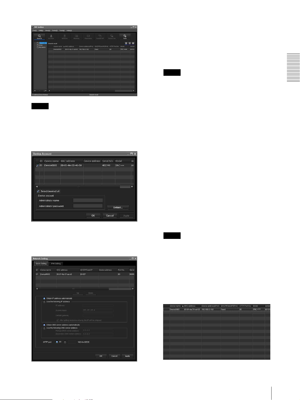
Click Search.
SNC toolbox detects the video network stations
connected to the local network and lists them.
9
Set the IP address.
To obtain the IP address automatically from a
DHCP server:
Select Obtain an IP address automatically.
The IP address, Subnet mask and Default gateway
are assigned automatically.
Note
Tip
The factory setting of the unit network is DHCP
mode.
7
Select a unit you want to assign an IP address from
the list and click Network.
The account settings screen is displayed.
When you select Obtain an IP address
automatically, make sure that the DHCP server is
operating on the network.
To specify the IP address manually:
Select Use the following IP address, and type the
IP address, Subnet mask and Default gateway in the
relevant boxes.
10
Set the DNS server address.
To obtain the DNS server addresses
automatically:
Select Obtain DNS server address automatically.
To specify the DNS server addresses manually:
Select Use the following DNS server address, and
type the Primary DNS server address and
Secondary DNS server address in the relevant
boxes.
11
Set the HTTP port No.
Normally, select 80 for the HTTP port No. To use
another port number, type a port number between
1024 and 65535 in the text box.
Preparation
8
Register the name and password of the
administrator and click OK.
The factory settings for both items are “admin.”
The Network Setting screen is displayed.
Note
When using a port number other than 80, check
with the network administrator first.
12
Confirm that all items are correctly set, then click
OK.
If “Setting OK” is displayed, the IP address is
correctly assigned.
13
When setting is finished, to access the unit directly,
double-click the unit name in the list.
Assigning the IP Address to the unit
7
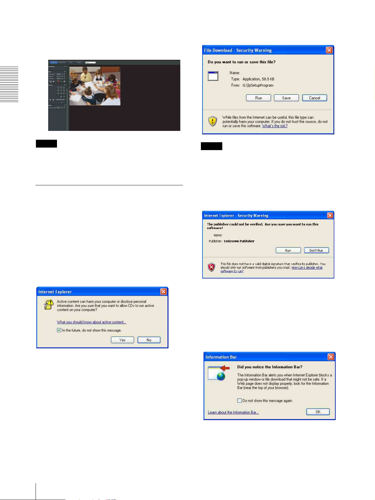
Preparation
The viewer screen of the video network station is
displayed on the Web browser.
Display sample
If the message “File Download – Security Warning”
appears, click Run.
Program name
Note
If the IP address is not set correctly, the viewer does not
appear after step 13. In that case, try to set the IP address
again.
When using Windows XP Service Pack 2 or later
Installing software
A warning message regarding the active contents may
appear when you install software such as SNC toolbox
from CD-ROM. In this case, operate as follows:
Example: In case of SNC toolbox
If message “Internet Explorer” appears, click Ye s.
Note
If you select Save in the “File Download – Security
Warning” dialog, you will not be able to perform the
installation correctly. Delete the downloaded file, and
click the Setup icon again.
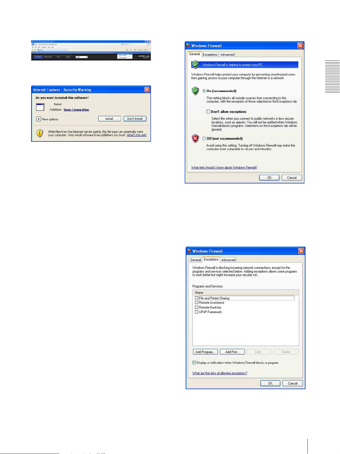
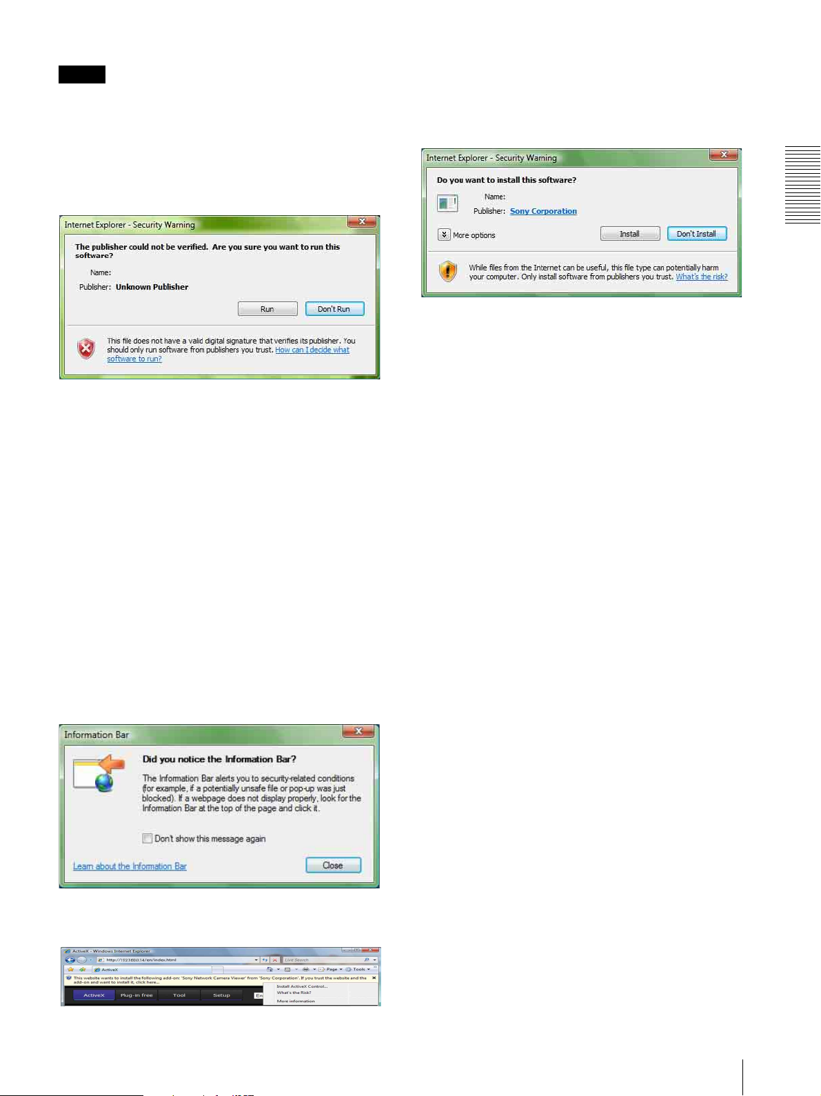
If the message “Internet Explorer – Security Warning”
appears, click Run.
Program name
The software installation starts.
Installing ActiveX Control
During installation of ActiveX Control, the
“Information Bar” or “Security Warning” may appear.
In this case, operate as follows:
8
Assigning the IP Address to the unit
If the message “Information Bar” appears, click OK.
If the information bar appears, click on the bar and select
Install ActiveX Control….
If “ Internet Explorer – Security Warning” appears, click
Install.
Program name
The installation of ActiveX Control starts. When
installation is completed, the main viewer or the Motion
detection menu appears.
Configuring Windows Firewall
SNC toolbox or SNC audio upload tool may not operate
correctly depending on the configuration of Windows
Firewall. (No video network stations are shown in the
list even if they are detected.) In this case, confirm the
Windows Firewall configuration as follows:
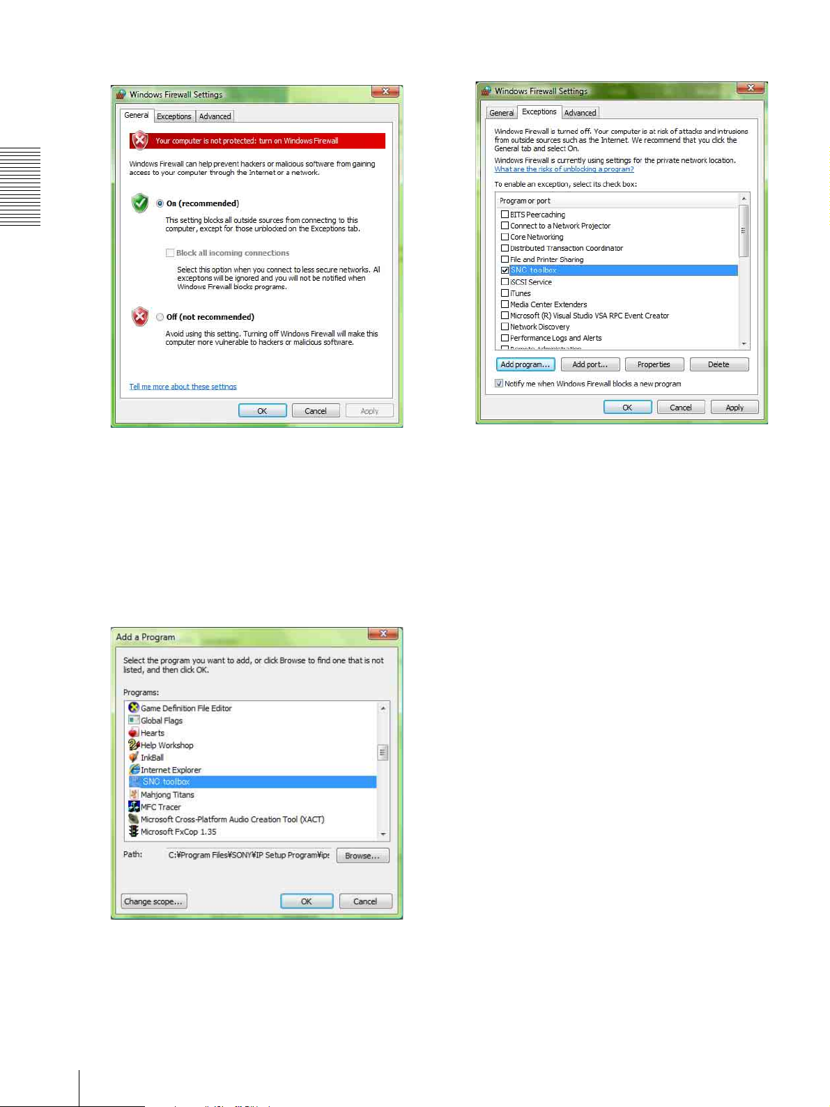
3
Select Windows Firewall and select Off in the
Windows Firewall dialog.
The video network station will be displayed in the
list.
If you want to keep Windows Firewall On, continue
with the following steps.
Preparation
Example: In case of SNC toolbox
1
Select Control Panel from the Start menu of
Windows.
2
Select Security Center of the working field.
4
Select the “Exceptions” tab.
5
Click Add Program….
Assigning the IP Address to the unit
9
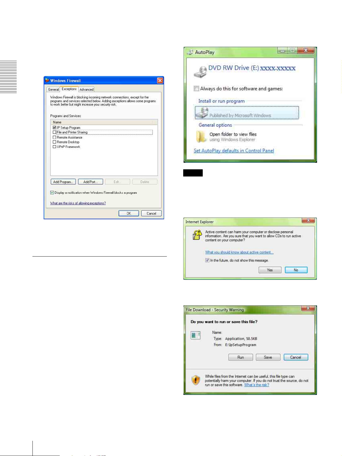
Preparation
6
In the Add Program dialog, select SNC toolbox and
click OK.
SNC toolbox is added to the Programs and Services
list.
7
Click OK.
If the pop-up “AutoPlay” appears when a CD-ROM is
inserted into the CD-ROM drive, click Install or run
program.
Program name
Note
If you click Open folder to view files, the Web browser
will not open automatically. In this case, double-click
the “index.htm” file in the CD-ROM.
When the above procedure is completed, the video
network station connected in the local network are
displayed in SNC toolbox.
When using Windows Vista
Installing software
A warning message regarding the active contents may
appear when you install software such as SNC toolbox
from the CD-ROM. In this case, operate as follows:
Example: In case of SNC toolbox
If the message “Internet Explorer” appears, click Ye s .
If the message “File Download – Security Warning”
appears, click Run.
Program name
10
Assigning the IP Address to the unit
Note
If you select Save in the “File Download – Security
Warning” dialog, you will not be able to perform
installation correctly. Delete the downloaded file, and
click the Setup icon again.
If the message “Internet Explorer – Security Warning”
appears, click Run.
Program name
If the message “User Account Control – An unidentified
program wants access to your computer” appears, click
Allow.
The software installation starts.
If the message “User Account Control – Windows needs
your permission to continue” appears, click Continue.
If “Internet Explorer – Security Warning” appears, click
Install.
Program name
Preparation
The installation of ActiveX Control starts. When
installation is completed, the main viewer or the Motion
detection menu appears.
Configuring Windows Firewall
SNC toolbox or SNC audio upload tool may not operate
correctly depending on the configuration of Windows
Firewall. (No cameras are shown in the list even if they
are detected.) In this case, confirm the Windows
Firewall configuration as follows:
Starting the software
When you start software such as SNC toolbox, the
message “User Account Control – An unidentified
program wants access to your computer” may appear. In
this case, click Allow.
Installing ActiveX Control
During installation of ActiveX Control, the information
bar or “Security Warning” may appear. In this case,
operate as follows:
If the message “Information Bar” appears, click Close.
Example: In the case of SNC toolbox
1
Select Control Panel from the Start menu of
Windows.
2
Click Windows Firewall.
3
Select Turn Windows Firewall on or off.
“User Account Control – Windows needs your
permission to continue” may appear. In this case,
click Continue.
If the information bar appears, click on the bar and select
Install ActiveX Control….
Assigning the IP Address to the unit
11
Preparation
4
Select Off in the “General” tab.
8
Click OK.
The video network station will be displayed in the
list.
If you want to keep Windows Firewall On, continue
with the following steps.
5
Select the “Exceptions” tab.
6
Click Add a Program….
7
If the Add a Program dialog appears, select SNC
toolbox and click OK.
When the above procedure is completed, the video
network station connected in the local network are
displayed in SNC toolbox.
SNC toolbox is added to the Program or port list.
12
Assigning the IP Address to the unit
Accessing the System Using the Web Browser
After the IP address has been assigned to the unit, check
that you can actually access the system using the Web
browser installed on your computer.
Use Internet Explorer as a Web browser.
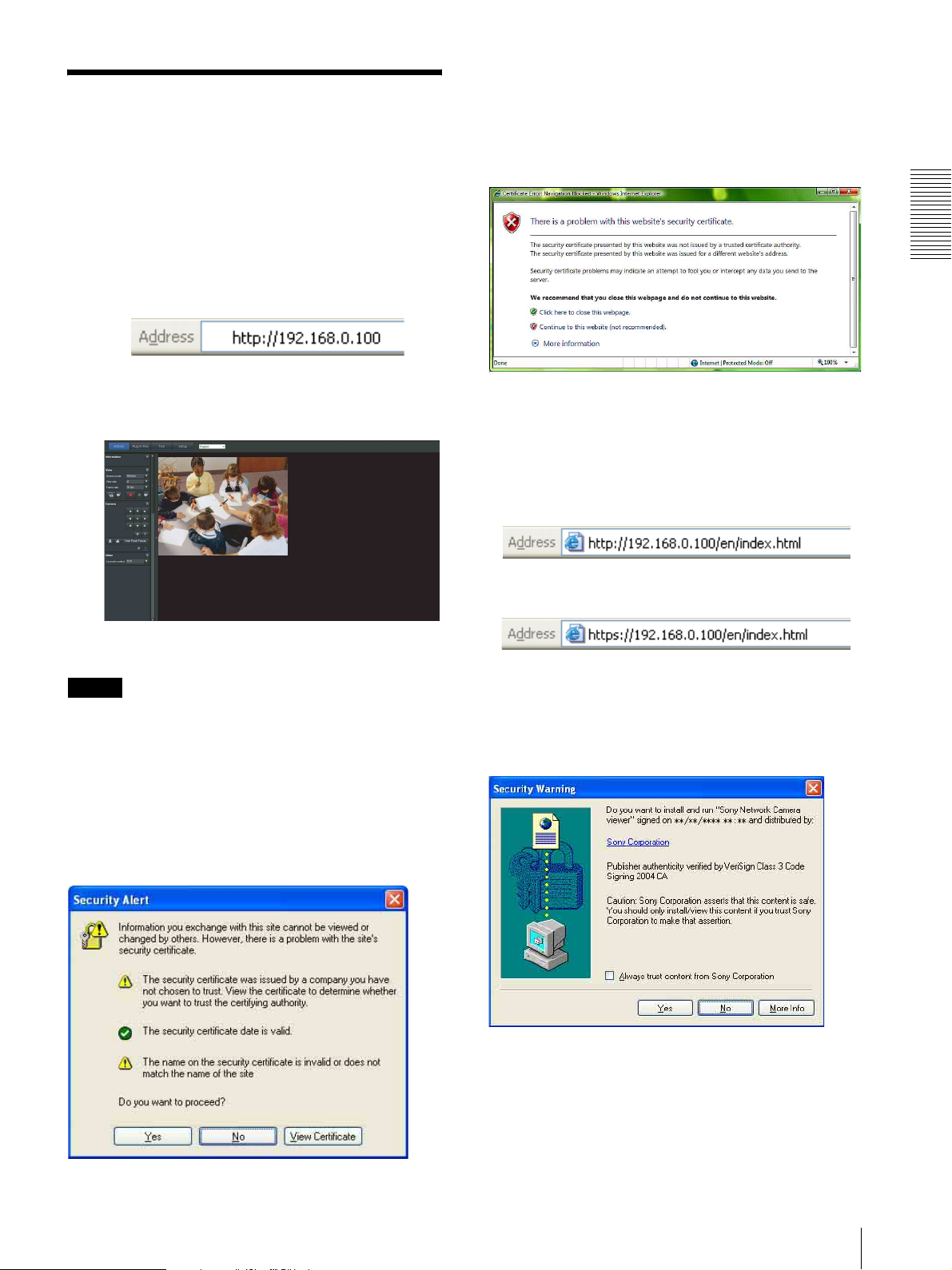
When Internet Explorer 7 is used
When you enter the unit IP address, “Certificate Error”
may appear according to the status of the certificate set
on the system. In this case, click Continue to this
website (not recommended). to continue.
The welcome page appears (in SSL communication).
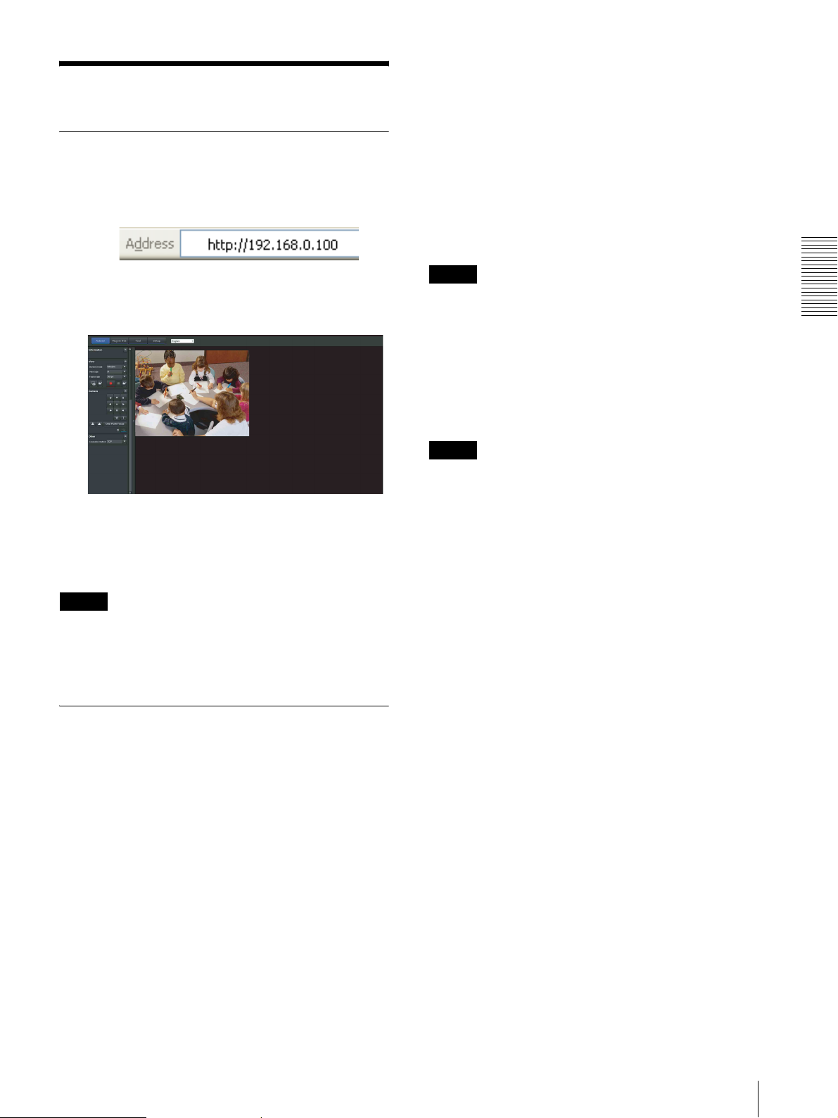
1
Start the Web browser on the computer and type the
IP address of the unit in the URL address bar.
The viewer window is displayed.
Display sample
Using the SSL function
Note
The model on sale in China does not support the SSL
function.
When Internet Explorer 6 is used
“Security Alert” dialog may appear according to the
status of the certificate. In this case, click Ye s to
continue.
The viewer window is displayed (in SSL
communication).
Preparation
When “Allow HTTP connection for some
clients” (page 42) is checked
To use HTTP and SSL connections separately to access,
enter the following in the address box of the browser.
For HTTP connection
For SSL connection
When the viewer of the unit is displayed
for the first time
“Security Warning” is displayed. When you click Ye s ,
ActiveX control is installed and the viewer is displayed.
Accessing the System Using the Web Browser
13

Preparation
Notes
• If Automatic configuration is enabled in the Local
Area Network (LAN) settings of Internet Explorer, the
image may not be displayed. In that case, disable
Automatic configuration and set the Proxy server
manually. For the setting of the Proxy server, consult
your network administrator.
• When you install ActiveX Control, you should be
logged in to the computer as Administrator.
• If you are using Windows XP Service Pack 2 or later,
or Windows Vista, the information bar or “Security
Warning” may appear. For details, see “Installing
ActiveX Control” in “When using Windows XP
Service Pack 2 or later” on page 8 or “Installing
ActiveX Control” in “When using Windows Vista” on
page 11.
Tip
The software is optimized for Internet Explorer using
medium font.
To display the viewer correctly
To operate the viewer correctly, set the security level of
Internet Explorer to Medium or lower, as follows:
1
Select Too ls from the menu bar for Internet
Explorer, then select Internet Options and click
the Security tab.
2
Click the Internet icon (when using the camera via
the Internet), or Local intranet icon (when using
the camera via a local network).
3
Set the slider to Medium or lower. (If the slider is
not displayed, click Default Level.)
When using antivirus software, etc., on
the computer
• When you use antivirus software, security software,
personal firewall or pop-up blocker on your computer,
the system performance may be reduced, for example,
the frame rate for displaying the image may be lower.
• The Web page displayed when you log in to the
camera uses JavaScript. The display of the Web page
may be affected if you use antivirus software or other
software described above on your computer.
14
Accessing the System Using the Web Browser

Basic Configuration by the Administrator
You can monitor the camera image by logging in with
the initial conditions set for this video network station.
You can also set various functions according to the
installing position, network conditions or purpose of the
camera.
We recommend you configure the following items
before monitoring images from the camera.
Setting contents Setting menu
Set the format of the image sent from the unit. Video codec Tab (page 36)
Select the brightness of the image sent from the unit. Brightness (page 35)
Select the quality of the image sent from the unit. Video codec Tab (page 36)
Select the view size of the image. View size (page 18)
Select whether the audio from the external microphone is sent or not. Microphone (page 34)
Synchronize the date and time of the unit with those of the computer. Date & time Tab (page 30)
Make the setting for sending the monitor image attached to an e-mail. e-Mail (SMTP) Menu (page 57)
Preparation
Set the user access right for the unit. User Menu (page 53)
Set a place to be watched beforehand. Preset position Menu (page 54)
Basic Configuration by the Administrator
15

Operating the unit
Administrator and User
This video network station identifies those who log in as
This section explains how to monitor the image from the
camera using your Web browser (Internet Explorer).
the Administrator or User.
The Administrator can use all the functions of this
video network station, including camera settings. The
The functions of the unit should be set by the
Administrator. For the setting of the unit, see
“Administrating the unit” on page 27.
User can use the functions for monitoring the image and
audio from the camera, and control the camera. The
Viewer mode setting is used to restrict the user's access
rights. There are five types of users.
Each type of user can use the corresponding functions below.
User
Operating the unit
Function Administrator
Monitor a live image z zzzzz
View the date and time z zzzzz
Control the frame rate (JPEG mode only) zz––––
Control the image view size z zzzz –
Save a still image and movie in the computer z zzzz –
Send an image file to the FTP server zz––––
Send an image attached to an e-mail zz––––
Record an image in the memory zz––––
Control the alarm output of the I/O port on the unit zz––––
Play an audio file (Voice alert) * zz––––
Switch the TCP/UDP transmission mode (Available in
MPEG4/H.264 mode only)
Call the preset position * z zzz ––
Perform the pan/tilt/zoom operation * zzz–––
Receive audio * z zzzzz
Select the codec mode z zzzz –
Control the setting menu z –––––
z Usable function
zz––––
Full Pan/Tilt Preset
position
Light View
– Not usable function
* SNT-EX101/SNT-EX104/SNT-EX154 only
The access rights of the administrator and the user can
be set in “Setting the User — User Menu” of the
Administrator menu on page 53.
16
Administrator and User
Logging in to System
Logging in as a user
1
Start the Web browser on your computer and type
the IP address of the system you want to monitor.
Plug-in free Viewer
This viewer allows the user to select from three image
display methods: JPEG, JPEG/FLASH or ActiveX
Viewer.
JPEG method: JPEG images will be displayed in
sequence.
JPEG/FLASH method: JPEG images will be displayed
in sequence.
ActiveX Viewer method: The image can be viewed
when the image display is set to JPEG, MPEG4 or
H.264.
The viewer is displayed.
Display sample:
Three types of viewer are available: ActiveX
Viewer, Plug-in free Viewer and custom homepage.
By default, ActiveX Viewer is displayed. To switch
the viewer, make changes to the Viewer menu
(page 81).
Note
If the main viewer does not start correctly, the security
level of the Internet Explorer may be set to higher than
Medium. See “To display the viewer correctly” on
page 14 and check the security level.
Notes
• If Automatic configuration is enabled in the Local
Area Network (LAN) Settings of Internet Explorer,
the camera image may not be displayed. In that case,
disable Automatic configuration and set the Proxy
server manually. For the setting of the Proxy server,
consult your network administrator.
• When you install ActiveX Control, you should be
logged in to the computer as the Administrator.
Tip
Every page of this software is optimized for Internet
Explorer in Medium font.
Operating the unit
About Viewers
You can use the following viewers.
ActiveX Viewer
This viewer can monitor the camera image in any of the
JPEG, MPEG4 and H.264 video codecs.
You must install this viewer when you access the main
viewer for the first time.
When you display the main viewer of the unit
for the first time
When you access the video network station using
ActiveX Viewer for the first time, the Security Warning
appears. Click Yes and install ActiveX Control. You can
use all the functions of the viewer with ActiveX Control.
Logging in to System
17
Configuration of Main
Control panel section
Viewer
This section explains the functions of the parts and
controls of the main viewer. For a detailed explanation
on each part or control, see the specified pages.
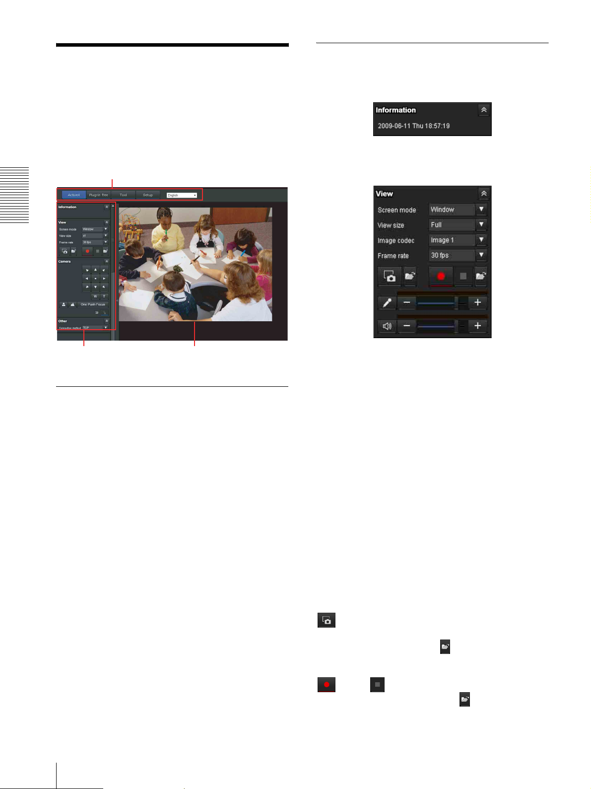
Main viewer using ActiveX Viewer
Main menu
Operating the unit
Control panel
section
Main menu
Monitor image
section
Information panel
Check the date and time here.
View panel
You can change the screen mode, size of the image,
image codec mode and frame rate. Also, still images and
movies can be saved (movie saving can also be stopped)
from here. Microphone and audio output levels can be
adjusted.
ActiveX
Displays the ActiveX viewer.
Plug-in free
Displays the Plug-in free viewer.
Tool
You can download system utility from here. (page 24)
This operation is only available when you are logged in
as administrator.
Set up
Click to display the Administrator menu. (page 27)
You can operate this function only when logging in as
the administrator.
Language
Set language from pull-down.
Screen Mode
Select Window or Full Screen.
View size
Selects the view size to be displayed.
Click View size list box to select the view size.
Full is determined by the image size specified in the
Camera menu (page 36).
Image Codec
Select an image codec mode.
Frame rate
(Displayed only when the camera image is in JPEG.)
Selects the frame rate to transmit images.
(Capture)
Click to capture a still image shot by the camera and to
store it in the computer. Click to open the folder to be
saved.
(Run)/ (Stop Save Video)
Runs and stops Save Video. Click to open the folder
to be saved.
18
Configuration of Main Viewer
Volume
(Displayed when Microphone (page 34) is set to On.)
Zoom control
Press to zoom out, and press to zoom in.
Zooming continues while the button remains pressed.
Adjust the microphone volume by moving the each
slider bar.
When you click , the icon changes to and the
microphone input stops. To input the microphone, click
again.
When you click , the icon changes to and the
microphone output stops. To output the microphone,
click again.
Notes
• This operation is not available on the SNT-EP104 or
SNT-EP154.
• Voice alert configuration is only available for CH1 on
the SNT-EX154.
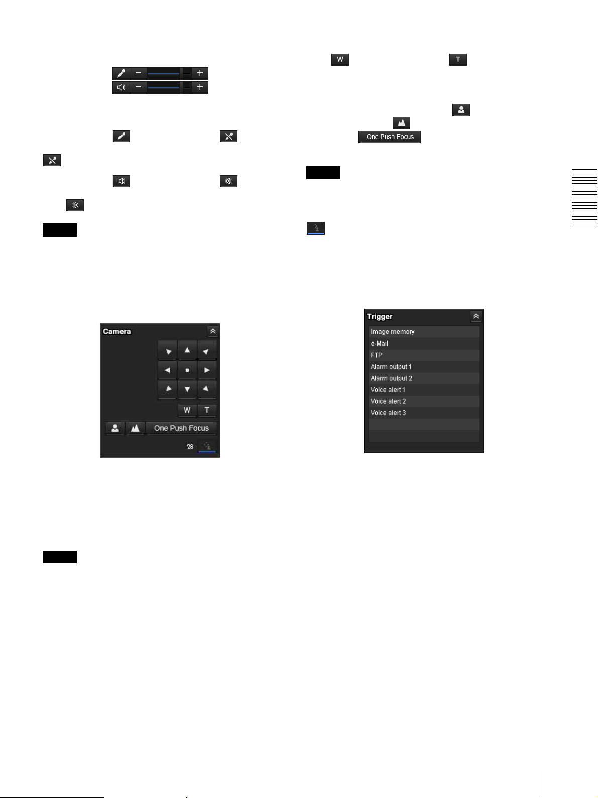
Camera control panel
Focus control
To focus on a nearby object, press . To focus on a
distant object, press .
By pressing , focus is set to the optimum
position.
Note
To control the focus manually, set Focus mode of the
Camera menu to Manual (page 34).
(Exclusive control)
Click this button to display the time remaining for
operation authority. However, if operation authority has
not been obtained, the waiting time is displayed.
Trigger panel
Operating the unit
On this panel, you can control the pan/tilt/home position
of the camera, adjust the zoom and switch focus mode
(page 21). In addition, you can obtain authority to
operate the camera when the exclusive control mode is
on.
Notes
• This operation is not available on the SNT-EP104 or
SNT-EP154.
• To operate the camera, it is necessary to have a camera
connected, and the connection/setting set correctly.
Pan/Tilt control
Click the arrow button the direction in which you want
to move the camera. Keep it pressed to move the camera
continuously.
The above is displayed only when Viewer mode
(page 53) is set to Full, and one or more triggers are
enabled in the Trigger menu (page 70).
The configured functions are displayed as buttons on
this panel.
Click the function button you want to use on the Trigger
panel. The selected function is activated. The selectable
functions are as follows:
• send still image files attached to an e-mail (page 22)
• send still image files to an FTP server (page 22)
• record still image files in the built-in memory or USB
memory (not supplied) (page 22)
• control the alarm output (page 23)
• play the audio file stored in the system (page 23)
Configuration of Main Viewer
19
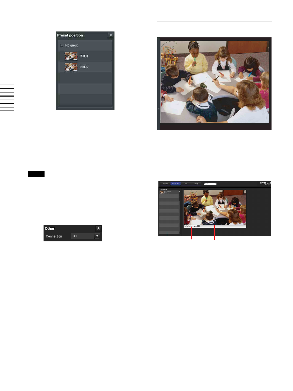
Preset position panel
Monitor image
Operating the unit
The above is displayed only when one or more preset
positions are stored in memory.
The registered preset position is displayed with a
thumbnail.
The image shot by the camera is shown here.
You can use the camera control panel bar to pan or tilt.
Select the Preset position name from the list. The
camera will move to the preset position that you have
stored in memory using the Preset position menu.
Notes
Plug-in free Viewer
Main viewer using Plug-in free Viewer
• This operation is not available on the SNT-EP104 or
SNT-EP154.
• To operate the camera, it is necessary to have a camera
connected, and the connection/setting set correctly.
Others panel
(Displayed only when the camera image is in MPEG4 or
Camera list Monitor
H.264, and the ActiveX Viewer is used.)
Control bar
screen
Monitor screen
You can switch between TCP and UDP (Unicast/
Multicast).
You can use the tool bar to pan or tilt.
Each click switches the transmission mode of the video/
audio data between TCP mode, UDP (Unicast) mode,
and UDP (Multicast) mode (page 23).
The last selected mode is saved in the computer, and will
stay selected for the next startup.
20
Configuration of Main Viewer
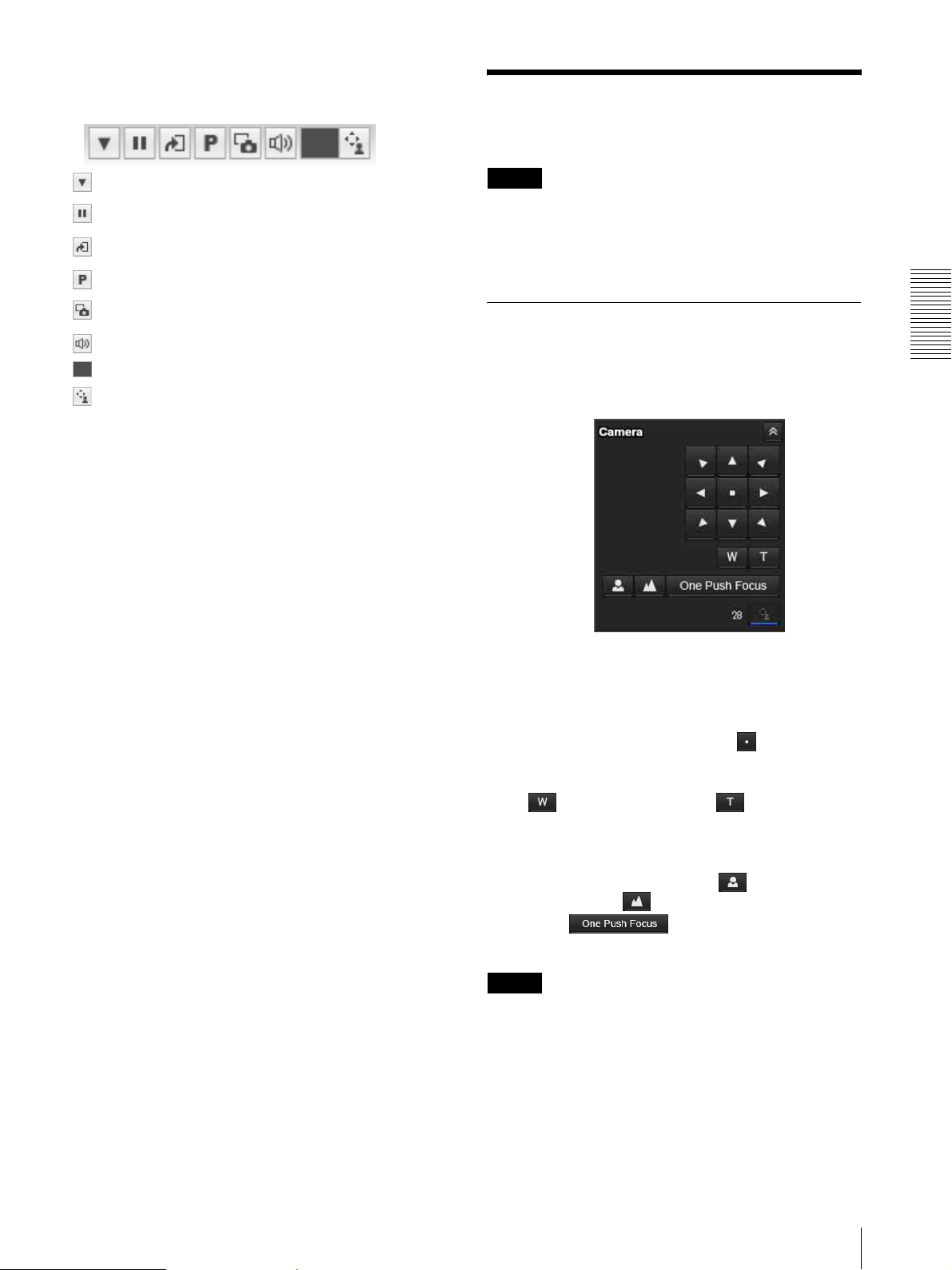
Control bar
The following operation buttons are available.
Operating the Camera
You can control pan/tilt, zoom and focus.
Setting
Play/Pause button
Trigger run button
Preset
Save still image button
Audio output volume slider
Control waiting time and control time for exclusive control
Exclusive control button
Camera list
The camera list is displayed when Camera list is set to
On in the viewer menu, and at least one camera is
registered in the unit list.
Notes
• This operation is not available on the SNT-EP104 or
SNT-EP154.
• To operate, make sure the connected camera is
configured correctly.
Controlling via the control panel
You can operate the camera direction, zoom, and focus
by using the control panel for the monitor image
currently displayed.
Operating the unit
Pan/Tilt control
Click the arrow button in the direction in which you
want to move the camera. Keep it pressed to move the
camera continuously.
To return to the home position, click .
Zoom control
Click to zoom out, and click to zoom in.
Zooming continues while the button remains pressed.
Focus control
To focus on a nearby object, click . To focus on a
distant object, click .
By clicking , the focus is set to the
optimum position.
Note
To control the focus manually, set Focus mode of the
Camera menu to Manual (page 34).
Operating the Camera
21
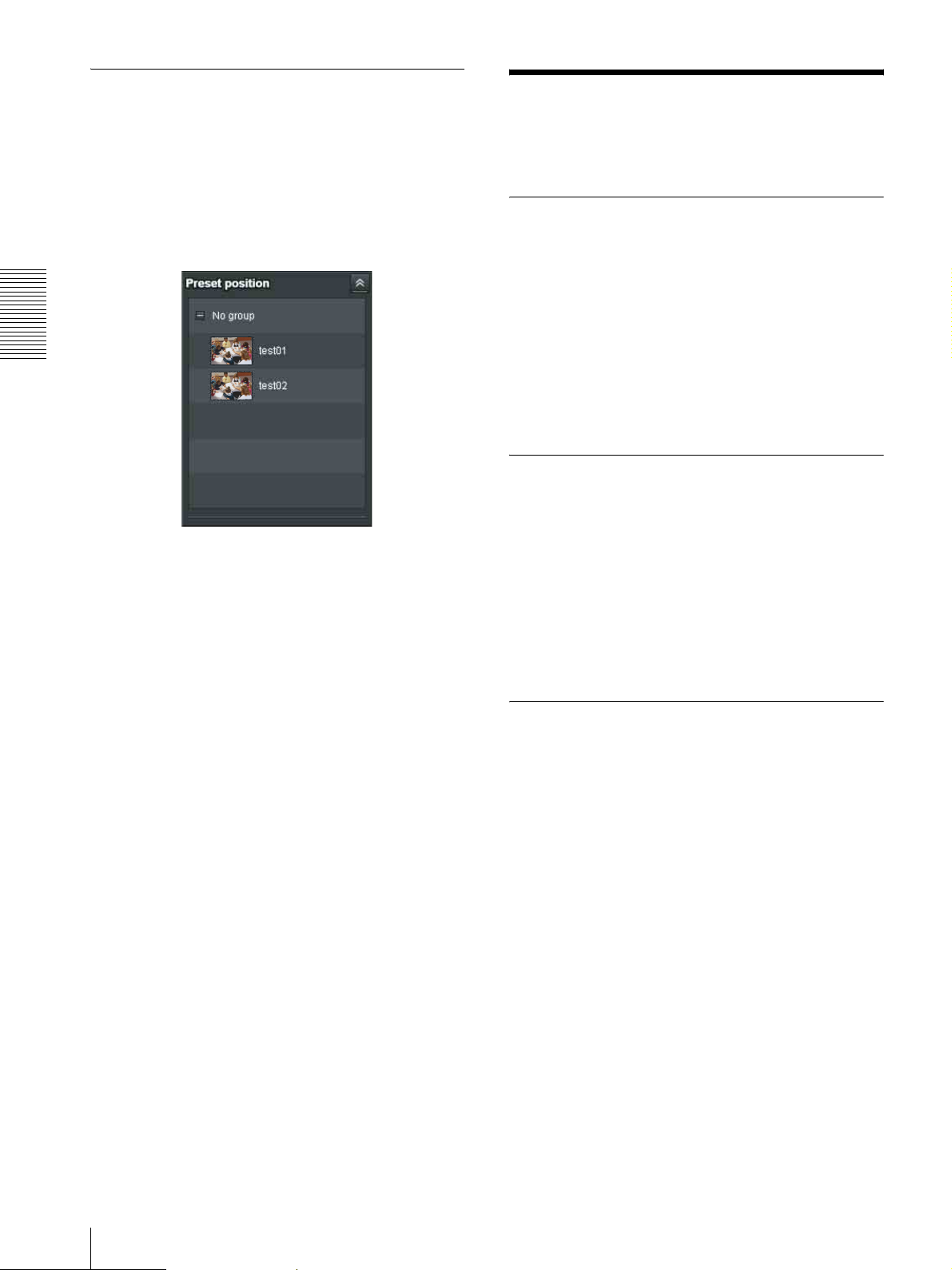
Moving the camera to a preset position
Select a preset position name from the Preset position
panel. The camera will move to the preset position that
you have stored in memory using the Preset position
menu (page 54).
Multiple preset positions can be organized by group
according to setting.
Operating the unit
Using the Trigger Button
You can execute various functions by clicking their
respective buttons on the Trigger panel.
Sending a monitor image via e-mail
You can send a captured still image by attaching it to an
e-mail.
To use this function, you need to make e-Mail (SMTP)
active and set the address in the Trigger menu of the
Administrator menu properly (page 70).
1
Click e-Mail (SMTP) on the Trigger panel.
The still image of the moment you click is captured,
and your e-mail with the image file attached is sent
to the specified mail address.
Sending a monitor image to an FTP server
You can send a captured still image to the FTP server.
To use this function, you need to make FTP active and
set the address in the Trigger menu of the Administrator
menu properly (page 71).
1
Click FTP client on the Trigger panel.
The still image of the moment you click is captured,
and the image file is sent to the FTP server.
Recording a camera image as a still image
You can capture a camera image as a still picture and
record it.
The still images are recorded in the built-in memory or
USB memory (not supplied).
To use this function, you need to make Image memory
active and set the details in the Trigger menu of the
Administrator menu (page 71).
1
Click Image memory on the Trigger panel.
The still image of the moment you click is captured,
and the image file is recorded.
22
Using the Trigger Button

Controlling alarm output
You can control Alarm output.
To use this function, you need to make Alarm output
active in the Trigger menu of the Administrator menu
(page 71).
1
Click Alarm output1 or Alarm output2 on the
Trigger panel.
The alarm output is switched by clicking.
The alarm output mode can be selected from
Toggle or Timer of Alarm output 1, 2 (page 71) in
the Trigger menu.
Tip
• For the connection of peripheral devices to the alarm
output of the I/O port, see the supplied Installation
Manual.
• The number of alarm outputs varies by model.
The number of selectable alarm output terminals is as
follows:
SNT-EX101: 2
SNT-EX104/SNT-EX154: 4
SNT-EP104/SNT-EP154: None
Playing an audio file stored in the
Switching TCP/UDP Transmission Mode
You can select TCP or UDP as the communication port
for video/audio data.
This function can be used when Mode (video codec
mode) is set to MPEG4 or H.264 and the ActiveX
Viewer is used.
Notes
• The function may not operate correctly if you use
personal firewall software or antivirus software on
your computer. In that case, disable the software or
select the TCP mode.
• If you are using Windows XP Service Pack 2 or later,
or Windows Vista, disable “Windows Firewall.” For
details, see “Configuring Windows Firewall” in
“When using Windows XP Service Pack 2 or later” on
page 9, or “Configuring Windows Firewall” in “When
using Windows Vista” on page 11.
1
Select TCP, UDP (Unicast) or UDP (Multicast)
from the Connection drop-down list in the Others
panel.
Operating the unit
system
You can play an audio file previously stored in the
system using the SNC audio upload tool.
To use this function, you need to make Voice alert1,
Voice alert2 and Voice alert3 active in the Trigger menu
of the Administrator menu (page 71).
1
Click Voi ce a l er t 1, Voice alert2 or Voice alert3 on
the Trigger panel.
Playback of the selected audio file starts and the
playback sound is output from the speaker
connected to the system.
Notes
• This operation is not available on the SNT-EP104 or
SNT-EP154.
• Voice alert configuration is only available for CH1 on
the SNT-EX154.
TCP: This is normally selected.
When TCP is selected as the communication port,
HTTP communication is adopted for video/audio
communications.
HTTP is the protocol used for reading the usual
Web page.
In an environment capable of reading Web pages,
you can watch or listen to video/audio by selecting
the TCP port.
UDP (Unicast): When UDP (Unicast) is selected
as the communication port, RTP (Real-time
Transport Protocol) is adopted for video/audio
communications. Since RTP is the protocol for
running video/audio data, the video/audio playback
is smoother than when TCP (HTTP) is selected. If
a firewall is installed between the system and the
computer, or depending on the network
environment, video/audio may not play back
properly when UDP (Unicast) is selected. In this
case, select TCP.
Switching TCP/UDP Transmission Mode
23
UDP (Multicast): This protocol is selectable when
Multicast streaming (page 37) is On. When UDP
(Multicast) is selected as the transmission port,
RTP (Real-time Transport Protocol) and UDP
multicast techniques are adopted for video/audio
transmission. By selecting it, the network
transmission load of the system can be reduced. If a
router that does not correspond to a multicast or
firewall is installed between the system and the
computer, video/audio may not play back properly.
In this case, select TCP or UDP (Unicast).
Operating the unit
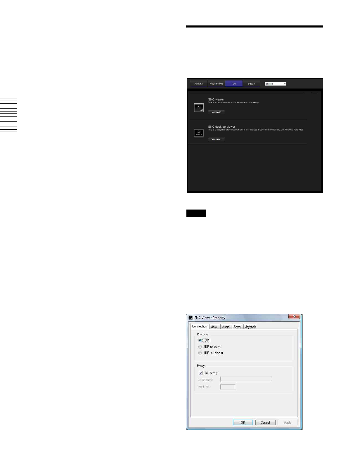
Using the System Utility
You can download system utility from the tools tab on
the main menu.
This operation is only available when you are logged in
as administrator.
To use the utility, click Download to begin download.
Note
Network camera (SNC-RH124/RS46N/RS46P,
SNC-RS44N/RS44P/RH164, SNC-RS86N/RS86P/
RS84N/RS84P) and video network station have a
common utility. For the video network station, some of
the utility functions cannot be used.
SNC Viewer
SNC Viewer is an application which allows you to set
the initial state of the viewer.
Connection tab
24
Using the System Utility
You can set the connection method.
Select the start-up connection from: TCP, UDP
Unicast, and UDP Multicast.
If TCP connection is selected, you can configure proxy
settings by selecting Use proxy.
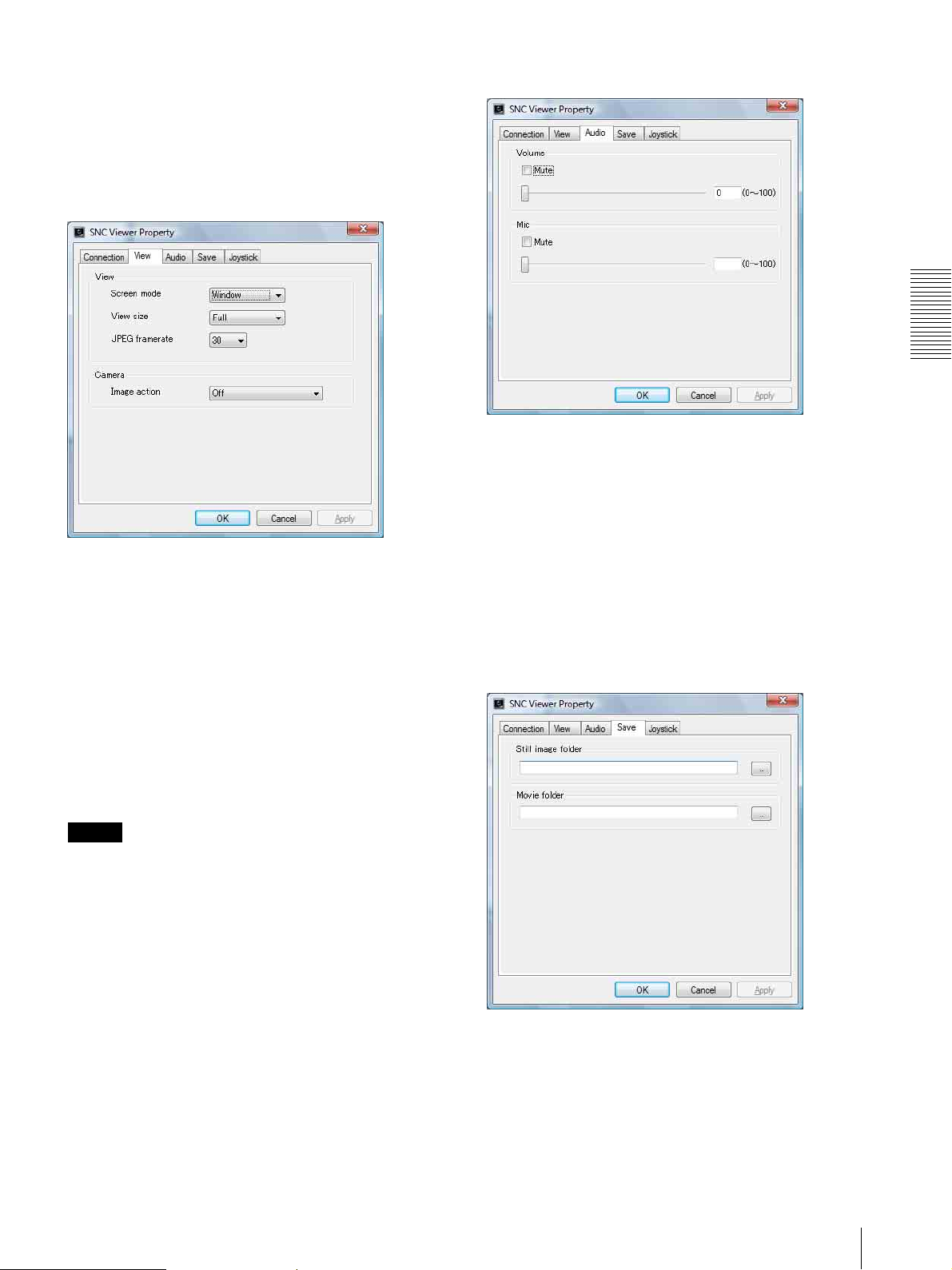
View tab
Audio tab
Operating the unit
Volume
Mute: Select this option to mute sound at start-up.
Use the slide bar to set the volume for start-up sound
output.
Screen mode
You can select Window or Full.
View size
You can select the view size.
JPEG framerate
You can set the frame rate for JPEG.
Image action
Select from the image operation modes Area zoom and
Vector dragging.
Note
This function cannot be used with video network station.
Mic
Mute: Select this option to mute microphone sound at
start-up.
Use the slide bar to set the volume for start-up
microphone input.
Save tab
Specify a folder to save the still images and movies to.
Using the System Utility
25
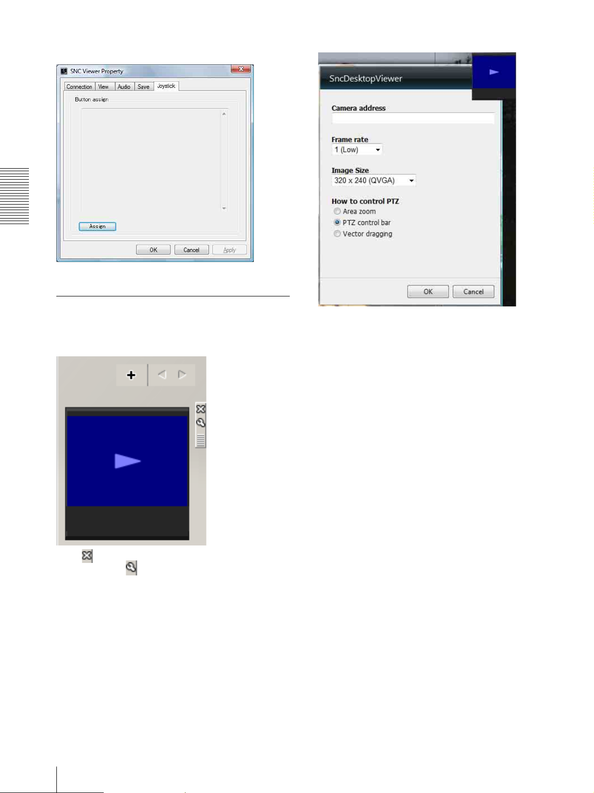
Joystick tab
Operating the unit
You can assign the joystick buttons here.
SNC Desktop Viewer
This is a gadget that displays the camera image in the
side bar of Windows Vista.
Click to exit Gadget.
When you click , you will see the following setting
screen.
Camera address
Set the IP address for the camera to display on the
Gadget.
Frame rate
Select the frame rate for the image to display on the
Gadget.
Image size
Select the image size for the image to display on the
Gadget.
26
Using the System Utility
Administrating the unit
3
Click the menu name (example: System) on the left
side of the Administrator menu.
The clicked menu appears.
This section explains how to set the functions of the unit
by the Administrator.
For details about monitoring the camera image, see
“Operating the unit” on page 16.
This section explains the basic operations and each
option of the Administrator menu.
Note on the display of menu options
The setting menus of this unit will clearly display only
the setting options that you can currently select. Grayed
out options cannot be selected.
Basic Operations of the Administrator Menu
You can use the Administrator menu to set all functions
to suit the user's needs.
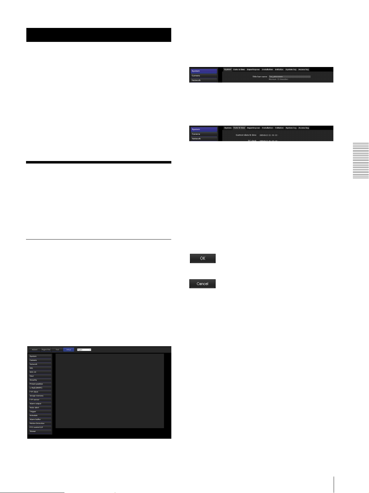
Click Setting in the viewer to display the Administrator
menu.
How to set up the Administrator
Example: “System” menu
4
Select the required tab above the menu, and set each
setting option in the tab.
Example: “Date & time” tab of “System” menu
See pages 29 to 83 for details of the menu tabs and
setting options.
5
After setting, click OK.
The settings you have made become active.
Click Cancel to nullify the set values and return to
the previous settings.
Buttons common to every menu
The following buttons are displayed on all the menus.
The functions of the buttons are the same on every
menu.
Administrating the unit
menu
1
Log in to the homepage to display the viewer.
For details, see “Logging in as a user” on page 17.
2
Click Setting on the main menu.
The authentication dialog appears. Enter the user
name and password for Administrator.
The user name “admin” and password “admin” are
set at the factory for the Administrator.
The Administrator menu appears.
Click this button to confirm the settings.
Click this button to nullify the set values and return to
the previous settings.
General notes on menus
• One-byte katakana character is not valid for any text
field, such as User name.
• After changing a setting on a menu, wait at least 10
seconds before turning off the power of the unit.
If the power is turned off immediately, the new setting
may not be stored correctly.
• If the unit settings are changed while watching the
main viewer, some settings cannot be restored. To
reflect the change on the opening main viewer, click
Refresh on the Web browser.
Basic Operations of the Administrator Menu
27

Configuration of the Administrator menu
System
Displays the System menu. For details, see
“Configuring the System — System Menu” (page 29).
Administrating the unit
Camera
Displays the Camera menu for setting the camera image
and audio. For details, see “Setting the Camera Image
and Audio — Camera Menu” (page 34).
Network
Displays the Network menu for setting the network
connection. For details, see “Configuring the Network
— Network Menu” (page 38).
SSL
Displays the SSL menu for performing SSL
communication between the client device and system.
(“Setting the SSL function — SSL Menu” on page 42)
802.1X
Displays the 802.1X menu for connecting the camera to
a network configured in compliance with the 802.1X
standard for port authentication. (“Using the 802.1X
Authentication Function — 802.1X Menu” on page 47)
Preset position
Displays the Preset position menu to register a position
you want to save. “Tour function,” which rotates the
registered positions, is also set here. (“Saving the
Camera Position and Action — Preset position Menu”
on page 54)
e-Mail (SMTP)
Displays the e-Mail (SMTP) menu for sending an e-
mail. (“Sending an Image via E-mail — e-Mail (SMTP)
Menu” on page 57)
FTP client
Displays the FTP client menu for sending an image/
audio file, etc., to an FTP server. (“Sending Images to
FTP Server — FTP client Menu” on page 60)
Image memory
Displays the Image memory menu for recording an
image/audio file, etc., in the built-in memory or in a
USB memory (not supplied) inserted in the unit.
(“Recording Images in Memory — Image memory
Menu” on page 63)
FTP server
Displays the FTP server menu for setting the FTP server
function of the unit. (“Downloading Images from the
system — FTP server Menu” on page 67)
Alarm output
Displays the Alarm output menu for setting the alarm
output terminal of the unit. (“Setting the Alarm Output
— Alarm output Menu” on page 67)
Voice alert
Displays the Voice alert menu for playing an audio file
stored in the system in synchronization with alarm
detection by the sensor input or the motion detection
function. (“Outputting Audio Linked to Alarm
Detection — Voice alert Menu” on page 69)
User
Displays the User menu for setting the log in user name
and password. (“Setting the User — User Menu” on
page 53)
Security
Displays the Security menu for specifying a computer
that is allowed to connect to the camera. (“Setting the
Security — Security Menu” on page 54)
28
Basic Operations of the Administrator Menu
Trig g e r
Displays the Trigger menu for designating the operation
to execute when you run a trigger. (“Setting the
Operations from the Viewer — Trigger Menu” on page
70)
Schedule
Displays the Schedule menu for the Preset position
function, e-Mail (SMTP) function, FTP client function,
Image memory function and Alarm output function,
Voice alert function, etc. (“Setting the Schedule —
Schedule Menu” on page 72)
Alarm buffer
Displays the Alarm buffer menu for the buffer for
storing the image and audio related to alarm detection.
(“Setting the Alarm Buffer — Alarm buffer Menu” on
page 73)
Motion Detection
Displays the Motion detection menu for the motion
detection function built into the system. (“Setting the
Motion Detection/VMF Function — Motion detection
Menu” on page 73)
PTZ control I/F
Displays the PTZ control I/F menu for communications
with external equipment through the external serial
terminal. (“Transmitting with External Equipment PTZ control I/F Menu” on page 80)
Configuring the System
— System Menu
When you click in the Administrator menu,
the System menu appears.
Use this menu to perform the principal settings of the
software.
The System menu has six tabs: System, Date & time,
Superimpose, Initialize, System log and Access log.
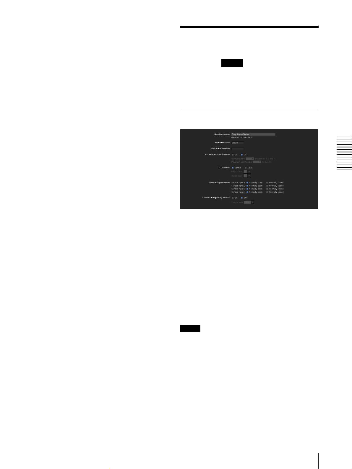
System Tab
System
Administrating the unit
Viewer
Displays the Viewer menu from which you can select the
viewer to use and configure advanced settings.
(“Configuring the Viewer — Viewer Menu” on page 81)
Title bar name
Type a name of up to 48 characters to be displayed on the
title bar. The characters typed here are displayed on the
title bar of the Web browser.
Serial number
The serial number of the camera is displayed.
Software version
The software version of this camera is displayed.
Exclusive control mode
Controls the authority to operate pan, tilt, zoom and
some other functions of the camera.
Notes
This operation is not available on the SNT-EP104 or
SNT-EP154.
On: Only one user has control authority. Set the
operation time for one user in Operation time.
If a user tries to operate a function during operation
by another user, the authority is controlled by the
settings of Operation time and Maximum wait
number.
Configuring the System — System Menu
29

Off: Multiple users can control pan, tilt and zoom at the
same time. When multiple users control these
functions at the same time, the last operation has
priority.
Operation time
Sets the time length for a user who has control authority.
The selectable range is from 10 to 600 seconds. This is
effective when Exclusive control mode is set to On.
Maximum wait number
Sets the number of users who are permitted to wait for
their turn for control authority during operation by one
user. The selectable number is from 0 to 10. This is
effective when Exclusive control mode is set to On.
Date & time Tab
Current date & time
Displays the date and time set on the unit.
Notes
•To use Exclusive control mode, the date and time of
the system and the connected computer must be set
Administrating the unit
correctly first.
•To use Exclusive control mode, do not disable the
Web browser Cookie. If it is disabled, this mode
cannot be used.
• When you change the Exclusive control mode
setting, click Refresh on the Web browser to reflect
the change when opening the main viewer page.
Sensor input mode
Set the detection mode of the signal input to the sensor
input terminal of the system.
Note
Sensor input mode configuration is not available for
SNT-EP104 and SNT-EP154.
Normally open: Detects the alarm when the sensor
input is short-circuited.
Normally closed: Detects the alarm when the sensor
input is open-circuited.
Camera tampering detection
Select On to activate the function to detect the camera
shaking. When you select On, you can select the Tamper
level.
Note
The camera tempering detection is not available on the
SNT-EP104 and SNT-EP154.
OK/Cancel
See “Buttons common to every menu” on page 27.
Note
After you have purchased the camera, be sure to check
the date and time of the camera and set as necessary.
PC clock
Displays the date and time set on your computer.
Date & time format
Select the format of date and time to be displayed in the
main viewer from the drop-down list.
You can select the format between yyyy-mm-dd
hh:mm:ss (year-month-day hour:minutes:seconds),
mm-dd-yyyy hh:mm:ss (month-day-year
hour:minutes:seconds), and dd-mm-yyyy hh:mm:ss
(day-month-year hour:minutes:seconds).
Adjust
Select how to set the day and time.
Keep current setting: Select if you do not need to set
the date and time.
Synchronize with PC: Select if you want to
synchronize the unit’s date and time with the
computer.
Manual setting: Select if you want to set the unit’s date
and time manually.
Select the year, month, date, hour, minutes and
seconds from each drop-down list.
Synchronize with NTP: Select if you want to
synchronize the unit’s date and time with those of the
time server called NTP server (Network Time
Protocol).
Set the NTP server when Synchronize with NTP is
selected.
30
Configuring the System — System Menu
 Loading...