

Sony IPELA SNC-VM772R Installation Manual

C-200-100-11 (1)
Network Camera
Installation Manual
Before operating the unit, please read this manual thoroughly
and retain it for future reference.
SNC-VM772R
© 2015 Sony Corporation

Table of Contents
About the Manuals
About the Manuals .................................................... 2
Location and Function of Part ................................. 3
Preparations .............................................................. 7
Change connections and cable wiring ................... 7
Installation ................................................................. 8
Deciding the Installation Location of the
Camera ................................................................. 8
Installing the Camera ............................................. 9
Installing the Camera (if you use a commercially
available LAN cable) ......................................... 10
Installing the Camera (If you use the conduit hole
on the side) ......................................................... 10
Installing the Camera (if you use a multi connector
cable) .................................................................. 10
Adjustment of the Shooting Direction and
Range ................................................................. 10
Attaching the Dome Casing ................................. 11
Important precautions .......................................... 12
Connection ............................................................... 13
Connecting to the Network .................................. 13
Connecting the Power Source .............................. 13
Connecting to 12 V DC or 24 V AC source ........ 13
Connecting to the power supply equipment
pursuant to IEEE802.3af .................................... 13
Connecting the I/O Cable .................................... 13
Assigning the IP address ........................................ 14
Specifications ........................................................... 15
Read This First (supplied)
The Read This First manual describes the URL of the
download site and the QR code. Be sure to read it.
Safety Regulations (supplied)
The Safety Regulations describes the secure usage of
camera. Be sure to read it.
Installation Manual (this document)
This Installation Manual describes the names and
functions of parts and controls of the Network Camera,
gives connection examples and explains how to set up the
camera. Be sure to read the Installation Manual before
operating.
User’s Guide/Application Guide/SNC
toolbox mobile Application Guide (Web)
The User’s Guide describes how to set up the camera and
how to control the camera via a Web browser.
These guides describe the following methods:
• How to control the camera via a web browser
• How to setup the camera
• How to adjust the view angle of the camera using a
smartphone or tablet
After installing and connecting the camera correctly
following the instructions in the Installation Manual,
operate the camera by referring to these guides.
2
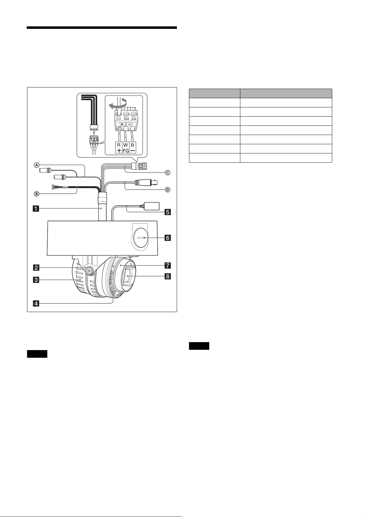
Location and Function of Part
Side
• MIC terminal (minijack, monaural)
Connect a commercially available microphone. This
jack supports pluginpower microphones.
B I/O (Input/Output) cable
This cable is provided with two sensor inputs and two
alarm outputs.
The wires of the cable control the following signals.
Color of wire Name
Red Sensor In 1+
White Sensor In 2+
Black Sensor In – (GND)
Yellow Alarm Out 1+
Brown Alarm Out 1–
Green Alarm Out 2+
Blue Alarm Out 2–
◆ For details on each function and required settings, see
the User’s Guide.
◆ For the wiring, see “Connecting the I/O Cable” on page
13.
C Power input cable (supplied and connected
to the camera at the factory)
Connect this cable to a 24 V AC or 12 V DC power supply
system.
You can screw an extension cable in the connector tip
attached at the end of the cable. When you use the power
input cable, connect GND to the center of the 3-pin
connector (FG).
The figure shows the camera without the dome casing.
a Multi connector cable (supplied)
Not connected to the camera at the factory.
Note
Using a device other than the recommended devices may
cause a failure or malfunction.
A Audio cable
The connector with the longer cable (SP) is used for the
line output connector, and the shorter cable (MIC) is used
for the microphone/line input connector.
Switch the microphone input and the line input in the
Video/Audio menu.
For details of the settings, refer to the User’s Guide.
• SP terminal (minijack, monaural)
Not used with this unit.
D BNC cable
Not used with this unit.
b Base (PAN)
c Camera block
d Infrared LED
Irradiates infrared light.
Notes
• Do not look at the infrared LED for a long time.
• Images may be dark if irradiated at a high temperature
environment.
e LAN cable (RJ-45) (supplied and connected
to the camera at the factory)
Connect this cable to a hub or computer on the 10BASE-T
or 100BASE-TX network using a commercially available
network cable (UTP, category 5).
3

f Side conduit hole (3/4 inches NPT or M27
(2.0 mm (
ø27 mm (1
3
/32inches)-pitched, hole diameter
1
/8inches)))
Connect a pipe to this hole. There is a conduit hole on the
side of the camera unit. The conduit hole cover is installed
in the side conduit hole at the factory.
Remove the cover as needed and connect the pipe to the
hole.
An M25 cable gland can be connected to the hole by
removing the nut inside the camera unit.
Note
Take care not to trap the cables between the camera and the
ceiling or the wall. If the cable is trapped, it may cause a
fire or electric shock due to breaking.
g Camera head
h Lens
4
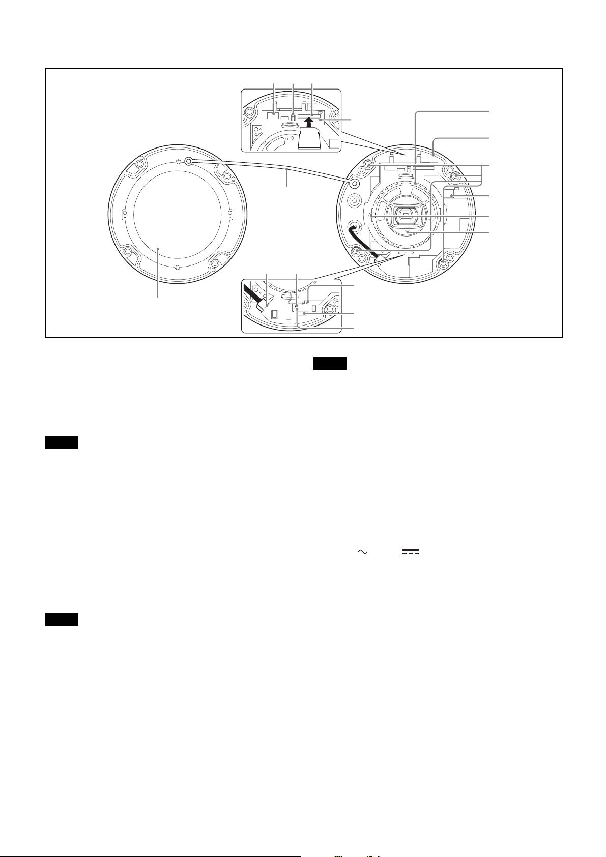
Inside
1
23
Infrared LED
4
5
6
qh
qg
a Connector dedicated to WLAN (Wireless LAN
terminal)
Attach a separately sold Sony product; USB Wireless LAN
Module IFU-WLM3 (hereafter WLAN module).
Use the module to view the angle adjustment when
installing the camera.
Notes
• When the WLAN module is mounted, the wired LAN is
not available.
• Using a device other than the specified devices may
cause a failure or malfunction.
• Do not attach the dome casing while attaching the
module to the connector.
• When using WLAN, use the camera at an outside air
temperature between 0°C to 40°C.
b SD OFF switch
By pressing the switch, the SD memory card can safely be
removed.
Note
After turning off the SD MOUNT indicator, the SD
memory card can be removed.
c SD card slot
This slot is used for separately sold SD memory cards.
Image data in the camera can be recorded to a memory card
by inserting it into the slot.
Align the notch of the memory card with the mark, and
gently insert the memory card to the slot until it clicks into
place.
This unit is compatible with the memory cards of SDXC
and SDHC standards only.
7
8
9
qdqf
q;
qa
qs
Note
For inquiries regarding verified SD memory cards, contact
your authorized Sony dealer.
d SD MOUNT indicator
When mounting the SD memory card, the indicator lights
up.
e Camera unit
f Camera unit mounting screws (four
positions)
Make sure to tighten the screws securely when installing
the camera.
g 24 V / 12 V (power input) connector
Connect the power input cable in the supplied multi
connector cable.
h Camera block fixing screw (tilt) (one position)
First, point the camera block in the desired direction, then
tighten the screw to secure in place.
i f TOP mark
Indicates the image direction.
j Reset switch
To reset the camera to the factory default settings, hold
down this switch with a pointed object and supply power
to the camera.
k AUDIO EXT CTRL (external control input/
output) connector
Connect the AUDIO and I/O cables in the supplied multi
connector cable.
5
 Loading...