

Sony IPELA SNC-RZ30N, SNC-RZ30P Install Manual

3-620-375-15 (1)
Network Camera
Installation Manual
Manuel d’installation
Manual de instalación
English
The supplied CD-ROM includes the User’s Guide that describes the setup
of the camera and the operations from the Web browser. Please read the
User’s Guide as well as this Installation Manual.
.
Français
Le CD-ROM fourni contient le Guide de l’utilisateur qui décrit
l’installation de la caméra et les opérations depuis le navigateur Internet.
Veuillez lire le Guide de l’utilisateur ainsi que ce manuel d’installation.
.
Español
El CD-ROM que se suministra incluye la Guía del usuario, que describe
la configuración de la cámara y las operaciones desde el explorador Web.
Lea la Guía del usuario, así como este Manual de instalación.
SNC-RZ30N
SNC-RZ30P
Version 2
GB
FR
ES
© 2002 Sony Corporation
Owner’s Record
The model and serial numbers are located at
the bottom. Record these numbers in the
spaces provided below.
Refer to these numbers whenever you call
upon your Sony dealer regarding this
product.
Model No. Serial No.
WARNING
To reduce a risk of fire or electric
shock, do not expose this product to
rain or moisture.
To avoid electrical shock, do not
open the cabinet. Refer servicing to
qualified personnel only.
Important
Nameplate is located on the bottom.
CAUTION for LAN port
For safety reason, do not connect the LAN
port to any network devices that might have
excessive voltage.
For customers in the U.S.A. (SNCRZ30N only)
This device complies with Part 15 of the
FCC Rules. Operation is subject to the
following two conditions: (1) This device
may not cause harmful interference, and
(2) this device must accept any
interference received, including
interference that may cause undesired
operation.
This equipment has been tested and found to
comply with the limits for a Class A digital
device, pursuant to part 15 of the FCC Rules.
These limits are designed to provide
reasonable protection against harmful
interference when the equipment is operated
in a commercial environment. This
equipment generates, uses, and can radiate
radio frequency energy and, if not installed
and used in accordance with the instruction
manual, may cause harmful interference to
radio communications. Operation of this
equipment in a residential area is likely to
cause harmful interference in which case the
GB
2
user will be required to correct the
interference at his own expense.
You are cautioned that any changes or
modifications not expressly approved in this
manual could void your authority to operate
this equipment.
The shielded interface cable recommended
in this manual must be used with this
equipment in order to comply with the limits
for a digital device pursuant to Subpart B of
Part 15 of FCC Rules.
For customers in Canada (SNCRZ30N only)
This Class A digital apparatus complies with
Canadian ICES-003.
Cet appareil mumérique de la classe A est
conforme à la norme NMB-003 du Canada.
For customers in Europe (SNCRZ30P only)
Warning
This is a Class A product. In a domestic
environment, this product may cause radio
interference in which case the user may be
required to take adequate measures.
In the case that interference should occur,
consult your nearest authorized Sony service
facility.
ATTENTION
The electromagnetic fields at specific
frequencies may influence the picture of the
unit.
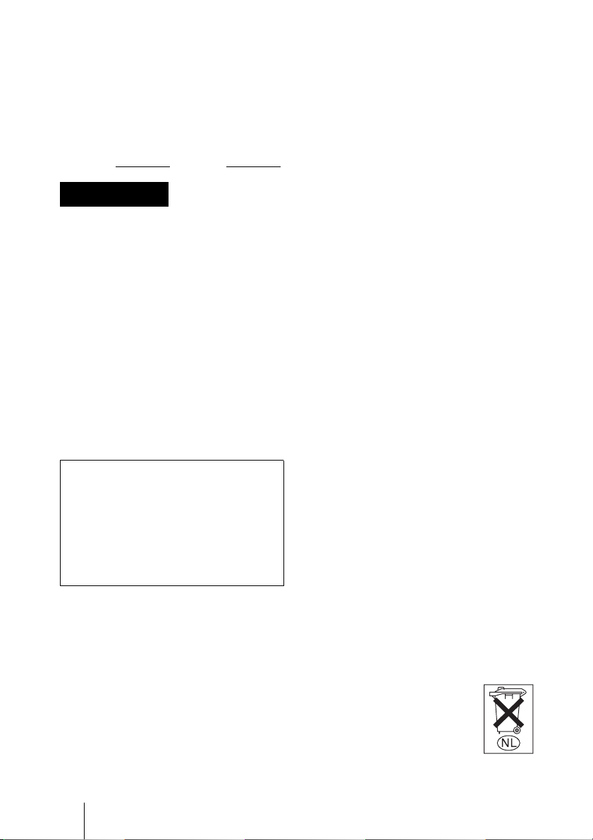
Voor de klanten in Nederland
• Dit apparaat bevat een vast ingebouwde
batterij die niet vervangen hoeft te worden
tijdens de levensduur van het apparaat.
• Raadpleeg uw leverancier indien de
batterij toch vervangen moet worden. De
batterij mag alleen vervangen worden
door vakbekwaam servicepersoneel.
• Gooi de batterij miet weg
maar lever deze in als klein
chemisch afval (KCA).
• Lever het apparaat aan het
einde van de levensduur in
voor recycling, de batterij zal
dan op correcte wijze
verwerket worden.

For Customers in Taiwan only
Table of Contents
Overview
Features .............................................. 4
Supplied Accessories ......................... 5
About the Supplied Manuals ............. 7
Names of Manuals ....................... 7
Using the CD-ROM Manuals ...... 7
Location and Functions of Parts and
Controls ............................................. 8
Basic Installation and
Connections
System Requirements ...................... 11
Attaching the Clamp Filters ............. 11
Assigning the IP Address to the
Camera ............................................. 12
Connecting the Camera to
a Computer ..................... 12
Connecting the Camera to a Local
Network .......................... 13
Assigning the IP Address Using the
Setup Program ................ 13
Accessing the Camera Using the
Web Browser .................. 15
Installing the Camera ....................... 16
Installing on the Ceiling ............. 17
Installing on the Desk Top ......... 20
Others
Precautions ...................................... 21
Operating Precautions ................ 21
Typical CCD Phenomena ................ 22
About a Memory Stick .................... 22
Specifications .................................. 24
Dimensions ................................ 26
Pin Assignment and Use of
I/O Port ........................... 27
Table of Contents
3
GB
GB

• The Network Camera system and related service is not a security service. When monitoring the image
and audio of the purchased Network Camera, there is a risk that the monitoring image or audio may be
viewed or used by a third-party via the network. It is provided only as a convenience for people to
easily access their cameras via the internet.
When you use the Network Camera, please take into account and ensure the privacy and portrait right
of the object at your own responsibility.
• Access to the camera or system is limited to the user setting up a user name and password only. No
further authentication is provided nor should the user presume that such filtering is done by the service.
• Sony assumes no liability should the service related to the Network Camera goes down or interrupted
for whatever reason.
B Overview
and a high-magnification zoom lens with
Features
optical zoom of 25 magnifications, electrical
zoom of 12 magnifications, giving 300
magnifications in total.
High-quality monitoring via the
network
You can monitor a high-quality live image
from the camera using the Web browser on
the computer connected to the 10BASE-T or
100BASE-TX network. The maximum
frame rate is 30 FPS for the SNC-RZ30N
and 25 FPS for the SNC-RZ30P. You can
also control the monitored image through
the Web browser to select the portion and
size of the image that you want to view.
Up to 50 users can view the image from one
camera at the same time.
Available Web browsers
Microsoft Internet Explorer
(Available OS: Windows 98/ 98SE/ Me/
NT4.0/ 2000/ XP
1)
Netscape Navigator
(Available OS: Windows 98/ 98SE/ Me/
NT4.0/ 2000/ XP
1)
)
2)
Ver. 6.2x
)
1)
Ver. 5.5 or 6.0
Remote-controllable high-speed
pan/tilt mechanism and highmagnification auto-focus zoom
lens
The camera is provided with a high-speed
(340° rotation within 2 seconds), wide-angle
(-170° to +170°) pan mechanism, a highspeed (115° rotation within 1.5 seconds),
wide-angle (-90° to +25°) tilt mechanism,
Image recording on the built-in
memory or recommended ATA
memory card
You can record still images from the camera
onto the camera’s built-in memory (about 8
MB) or recommended ATA memory card (a
“Memory Stick” inserted into a PC card
adaptor). You can record a still image at the
moment when a trigger by the external
sensor input, built-in activity detection
function or manual trigger button occurs, or
still images sequentially for a determined
period before and after the trigger. Periodic
recording of still images is also possible.
Image transmission using an Email or FTP server
You can send a still image from the camera
as an attachment of an E-mail or to an FTP
server, at the moment when a trigger by the
external sensor input, built-in activity
detection function or manual trigger button
occurs. You can also send still images
sequentially for a determined period before
and after the trigger to an FTP server, or send
them periodically.
If you use the FTP client software of the
computer, you can also search for and
receive the still image recorded in the built-
. . . . . . . . . . . . . . . . . . . . . . . . . . . . . . . . . . . . . . . . . . . . . . . . . . . . . . . . . . . . . . . . . . . . . . . . . . . . . . . . . . . . . .
1) Microsoft, Windows, Internet Explorer and MS-DOS are registered trademarks of Microsoft
Corporation in the United States and/or other countries.
2) Netscape and Navigator are registered trademarks of Netscape Communications Corporation in
the U.S. and other countries.
GB
4 Features
in memory or recommended ATA memory
card (a “Memory Stick” inserted into a PC
card adaptor) inserted into the PC card slot
of the camera.
Supplied
Accessories
Preset positions and Tour
programs
You can save up to 16 preset positions (pan,
tilt and zoom positions) of the camera, and
up to 5 tour programs composed from the
preset positions. You can activate the preset
positions by synchronizing with the external
sensor input or built-in activity detection
function.
Alarm output
The camera is equipped with two sets of
alarm outputs. You can use them to control
peripheral devices by synchronizing with the
external sensor inputs, built-in activity
detection function, manual trigger button,
Day/Night function or timer.
Transparency-type RS-232C/RS485 interface
If you connect peripheral devices to the
camera via the RS-232C or RS-485
interface, you can control the devices from
the computer via the network and receive
data from these devices.
Analog video output
The analog video output allows connecting a
VTR or TV monitor for local image
recording and monitoring.
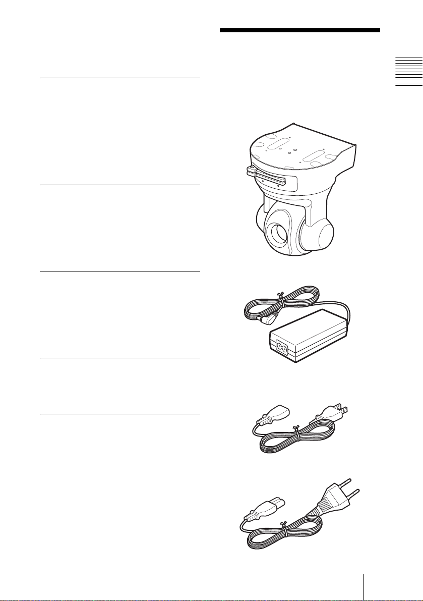
When you unpack, check that all the
supplied accessories are included.
Camera (1)
AC power adaptor (1)
AC power cord (1)
USA and Canadian model
Overview
Image flip
By default, the images from the camera are
displayed normally when the camera is
installed on the ceiling. Using the image flip
function, you can flip the images from the
camera vertically so that they are seen in
correct way when the camera is placed
upright on the desk top.
European model
Supplied Accessories
GB
5
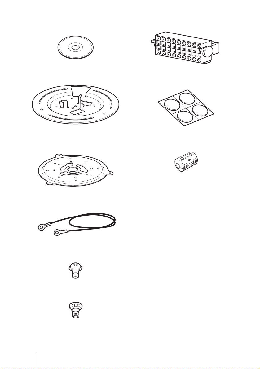
CD-ROM (including the Setup
Program and User’s Guide) (1)
I/O receptacle (1)
Ceiling bracket (A) (1)
Ceiling bracket (B) (1)
Wire rope (1)
Screw +M 3×6 (7)
Rubber foot (4)
Clamp filter (2)
Installation Manual (1)
Shoulder screw M4 (1)
GB
6 Supplied Accessories

About the Supplied
Manuals
Names of Manuals
The following manuals are supplied with
this unit.
Installation Manual (this document)
The Installation Manual describes the names
and functions of the parts of the camera, the
installation and connections of the camera,
etc. Be sure to read it before operating the
camera.
User’s Guide (stored in the CDROM)
The User’s Guide describes the setup of the
camera and the operations from the Web
browser.
To open the User’s Guide, see “Using the
CD-ROM Manuals” below.
Using the CD-ROM Manuals
When these requirements are not met, access
to the CD-ROM disc may be slow, or not
possible at all.
Preparations
The Adobe Acrobat
later must be installed on your computer in
order to use the User’s Guide contained in
the CD-ROM disc.
Note
If Adobe Acrobat Reader is not installed, it
may be downloaded from the following
URL:
http://www.adobe.com/products/acrobat/
readstep.html
2)
Reader Version 4.0 or
Reading the manual in the CD-ROM
To read the User’s Guide contained in the
CD-ROM disc, do the following.
1 Insert the supplied CD-ROM disc into
your CD-ROM drive.
2 Double-click the Manual folder.
3 Double-click the version you want to
read.
A PDF file of the User’s Guide opens.
Overview
The supplied CD-ROM disc includes the
User’s Guides for the SNC-RZ30N/RZ30P
(Japanese, English, French, German,
Spanish, Italian and Chinese versions).
Note
If you lose the CD-ROM disc or become
unable to read its content, for example
because of a hardware failure, contact a
Sony service representative.
CD-ROM System Requirements
The following are required to access the
supplied CD-ROM disc.
• Computer: PC with MMX Pentium
MHz or faster CPU
• Installed memory: 64 MB or more
• CD-ROM drive: × 8 or faster
• Monitor: Monitor supporting resolution of
800 × 600 or higher
. . . . . . . . . . . . . . . . . . . . . . . . . . . . . . . . . . . . . . . . . . . . . . . . . . . . . . . . . . . . . . . . . . . . . . . . . . . . . . . . . . . . .
1) MMX and Pentium are registered trademarks of Intel Corporation or its subsidiaries in the United
States and other countries.
2) Adobe and Acrobat are registered trademarks of Adobe Systems Incorporated in the United States
and/or other countries.
1)
166
About the Supplied Manuals
7
GB
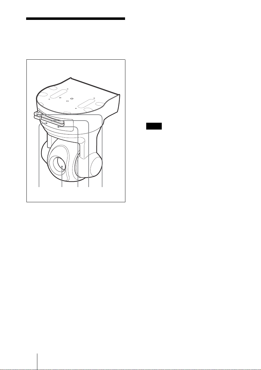
Location and
Functions of Parts
and Controls
Front
12345
3 POWER indicator (green)
When the power is supplied to the
camera, the camera starts checking the
system. If the system is normal, this
indicator lights up.
If a system error occurs, this indicator
flashes every second. In this case,
consult your authorized Sony dealer.
4 PC card slots
Insert the recommended ATA memory
card (“Memory Stick” in the PC card
adaptor) into each slot.
The dummy cards are inserted at the
factory. Remove the dummy card when
you use the slot.
Note
Insert the PC card with its front side
towards the NETWORK and POWER
indicators.
5 PC card levers
Press the lever to remove the PC card
from the camera.
1 NETWORK indicator (orange/
green)
The indicator flashes in orange when the
camera is connected to the 10BASE-T
network; it flashes in green when the
camera is connected to the 100BASETX network.
The indicator goes off when the camera
is not connected to the network.
2 Lens
A × 25 optical zoom, auto-focus lens is
mounted as standard equipment.
GB
8 Location and Functions of Parts and Controls
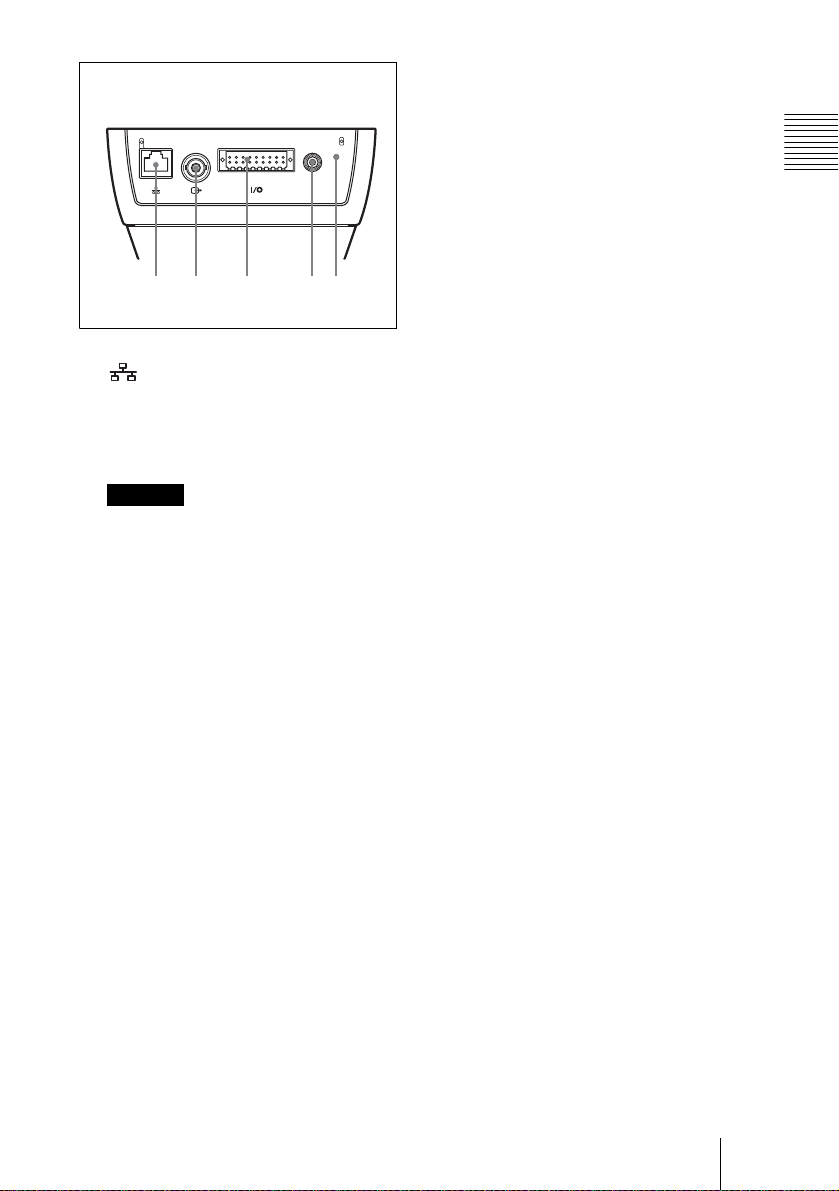
67 8 9q
Rear
24681012141618
13579111315
17
!
DC IN 12V
;
6 (Ethernet) port
Connect to a hub or computer on the
10BASE-T or 100BASE-TX network
using an Ethernet cable (UTP, category
5).
Caution
When using a LAN cable: For safety, do
not connect to the connector for
peripheral device wiring that might have
excessive voltage.
7 T (video output) connector
(BNC type)
Outputs a composite video signal.
Connect to a composite video input
connector of a video monitor, VCR, etc.
Day/Night function or the timer
function.
For details on each function and
required settings, see the User’s Guide
stored in the supplied CD-ROM.
For the pin assignment and wiring, see
“Pin Assignment and Use of I/O Port”
on page 27.
9 DC IN 12 V (power input)
connector
Connect the supplied AC power adaptor.
q; Reset switch
To reset the camera to the factory default
settings, hold down this switch and
supply the power to the camera.
Overview
8 I/O (Input/Output) port
This port is provided with RS-485 or
RS-232C port, three sensor inputs and
two alarm outputs.
The RS-485 or RS-232C port is used
when you connect peripheral devices to
the camera using the RS-485 or RS232C interface, and control the devices
from the computer or receive data from
the devices via the network.
The sensor inputs are used to
synchronize the camera operation with
E-mail or other applications.
The alarm outputs are used to control the
connected peripheral devices by
synchronizing with an external sensor
input, the built-in activity detection
function, a manual trigger button, the
Location and Functions of Parts and Controls
GB
9
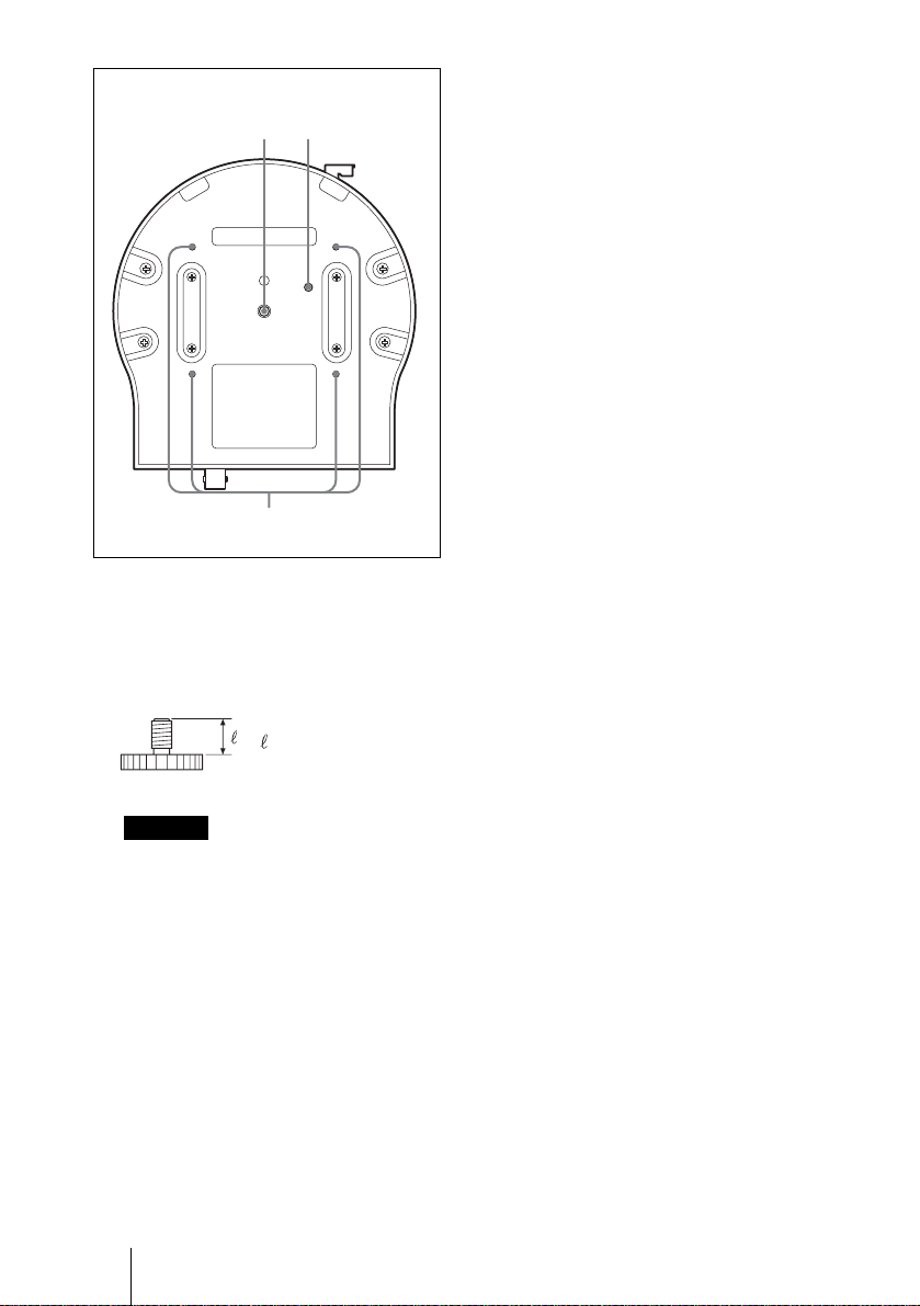
qaq
Bottom
s
qd
qa Installation/tripod hole
Use this hole when attaching the camera
to a tripod (screw: 1/4”, 20 UNC)
The following mounting screw can be
used.
bracket (A) to these holes using the
supplied screws.
For installing on the ceiling, see page
17.
U1/4”, 20 UNC
= 4.5 mm ± 0.2 mm
(ISO standard)
Caution
Use the mounting screw whose length is
4.5 mm ± 0.2 mm only. Use of other
screws may cause improper mounting
and damage parts inside the camera.
qs Wire rope mounting screw hole
When installing the camera to the
ceiling, secure the supplied wire rope to
this hole using the supplied shoulder
screw.
For installing on the ceiling, see page
17.
qd Ceiling bracket mounting screw
holes
When installing the camera to the
ceiling, secure the supplied ceiling
GB
10 Location and Functions of Parts and Controls
B Basic Installation and Connections
System
Requirements
Processor
Pentium III 500 MHz or higher (Pentium 4,
1 GHz or higher recommended)
RAM
128 MB or more
OS
Windows 98/ 98SE/ Me/ NT4.0/ 2000/ XP
Web browser
Internet Explorer Ver. 5.5 or Ver. 6.0
Netscape Navigator Ver. 6.2x
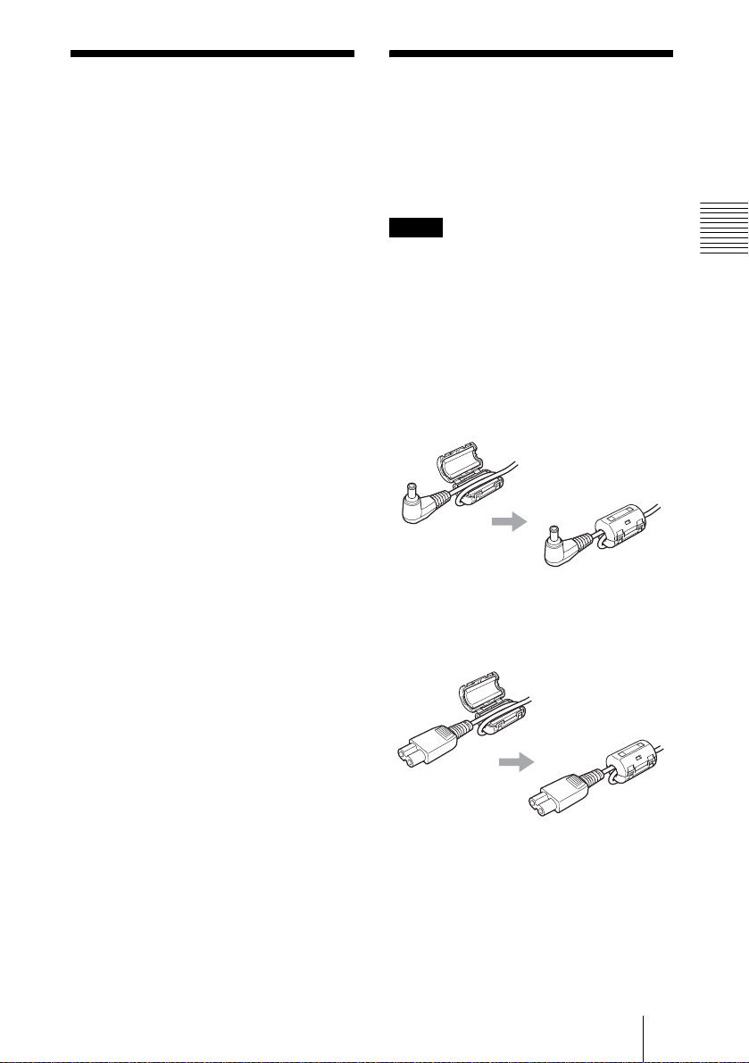
Attaching the Clamp
Filters
Before using the camera, attach the supplied
clamp filters to the AC power adaptor cable
and AC power cord, as shown below.
Notes
• Be careful not to clamp the cable between
the pawls of the clamp filter.
• Be sure to attach the clamp filters as close
as possible to the AC power adaptor and
AC power cord ends. The clamp filters
will not be effective unless they are
immediately adjacent to the cable ends.
Attach the clamp filter to the plug end
of the AC power adaptor cable.
Basic Installation and Connections
Attach the clamp filter to the AC
power adaptor end of the AC power
cord.
System Requirements/Attaching the Clamp Filters
11
GB
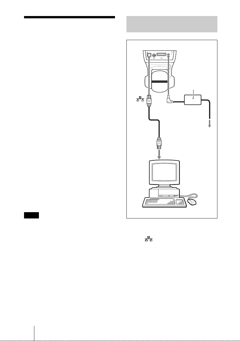
Assigning the IP
Address to the
Connecting the Camera to a
Computer
Camera
To connect the camera to a network, you
need to assign a new IP address to the
camera.
Before assigning the IP address, connect the
camera to a computer or a network. To
connect to the computer, use a commercially
available Ethernet cable (cross cable). To
connect to the network, use a commercially
available Ethernet cable (straight cable).
You can assign the IP address in two ways:
• Using the setup program stored in
the supplied CD-ROM
For details on the operations, see
“Assigning the IP Address Using the Setup
Program” on page 13.
• Using the ARP (Address Resolution
Protocol) commands
Open the DOS window on the computer and
enter the specified ARP commands.
For details on the operations, see
“Assigning the IP Address to the Camera
Using ARP Commands” in the User’s Guide
stored in the supplied CD-ROM.
Note
For determining the IP address to be
assigned to the camera, consult your system
administrator.
SNC-RZ30N/RZ30P (rear)
Ethernet
cable (cross,
not supplied)
24681012141618
13579111315
17
!
DC IN 12V
DC IN
12 V
Network
connector
Computer
AC power adaptor
(supplied)
Power cord
(supplied)
to an AC
outlet
1 Using a commercially available
Ethernet cable (cross), connect
the (Ethernet) port of the
camera to the network
connector of a computer.
GB
12 Assigning the IP Address to the Camera
2 Connect the power cord to the
AC power adaptor (both
supplied), and connect the DC
IN 12 V connector of the camera
to an AC outlet.
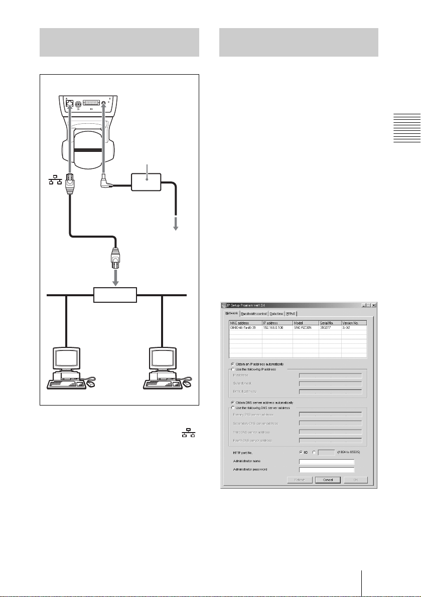
Connecting the Camera to a
Local Network
SNC-RZ30N/RZ30P (rear)
24681012141618
13579111315
17
!
DC IN 12V
Assigning the IP Address
Using the Setup Program
1 Insert the supplied CD-ROM
disc into your CD-ROM drive.
2 Double-click the Setup folder in
the CD-ROM drive.
AC power adaptor
(supplied)
DC IN
12 V
Ethernet cable
(straight, not
supplied)
Power cord
(supplied)
to an AC
outlet
10BASE-T/
100BASE-TX
Hub
Network
1 Using a commercially available
Ethernet cable, connect the
(Ethernet) port to a hub in the
network.
3 Double-click Setup.exe.
4 Install the IP Setup Program to
your computer following the
wizard displayed.
If the Software License Agreement is
displayed, read it carefully and accept
the agreement to continue the
installation.
5 Start the IP Setup Program.
The program detects the SNC-RZ30
cameras connected on the local network
and lists them on the Network tab
window.
Basic Installation and Connections
2 Connect the power cord to the
AC power adaptor (both
supplied), and connect the DC
IN 12 V connector of the camera
to an AC outlet.
Assigning the IP Address to the Camera
13
GB

6 Click on the camera you want to
assign a new IP address in the
list.
The network settings for the selected
camera are displayed.
7 Set the IP address.
To obtain the IP address
automatically from a DHCP
server:
Select Obtain an IP address
automatically.
The IP address, Subnet mask and
Default gateway are assigned
automatically.
To specify the IP address
manually:
Select Use the following IP address,
and type the IP address, Subnet mask
and Default gateway in each box.
8 Set the primary DNS Server
address and, if necessary,
secondary DNS server address.
To obtain the DNS server
addresses automatically:
Select Obtain DNS server
automatically.
The default settings of both items are
“admin.”
11Confirm that all items are
correctly set, then click OK.
If “Setting OK” is displayed, the IP
address is correctly assigned.
To specify the DNS server
addresses manually:
Select Use the following DNS server,
and type the primary DNS server
address and Secondary DNS address in
each box.
Note
The Third DNS Server address and
Fourth DNS Server address are invalid
for this camera.
9 Set the HTTP port number.
Normally select 80 for the HTTP port
No. To use another port number, select
the text box and type a port number
between 1024 and 65535.
10Type the Administrator name
and Administrator password.
GB
14 Assigning the IP Address to the Camera
Accessing the Camera Using
the Web Browser
When the IP address has been assigned to
the camera, check that you can actually
access the camera using the Web browser
installed in your computer.
This section explains how to access the
camera using the Internet Explorer.
For details on the operations using the Web
browser, i.e. for using a Web browser that is
not the Internet Explorer, see the User’s
Guide stored in the supplied CD-ROM.
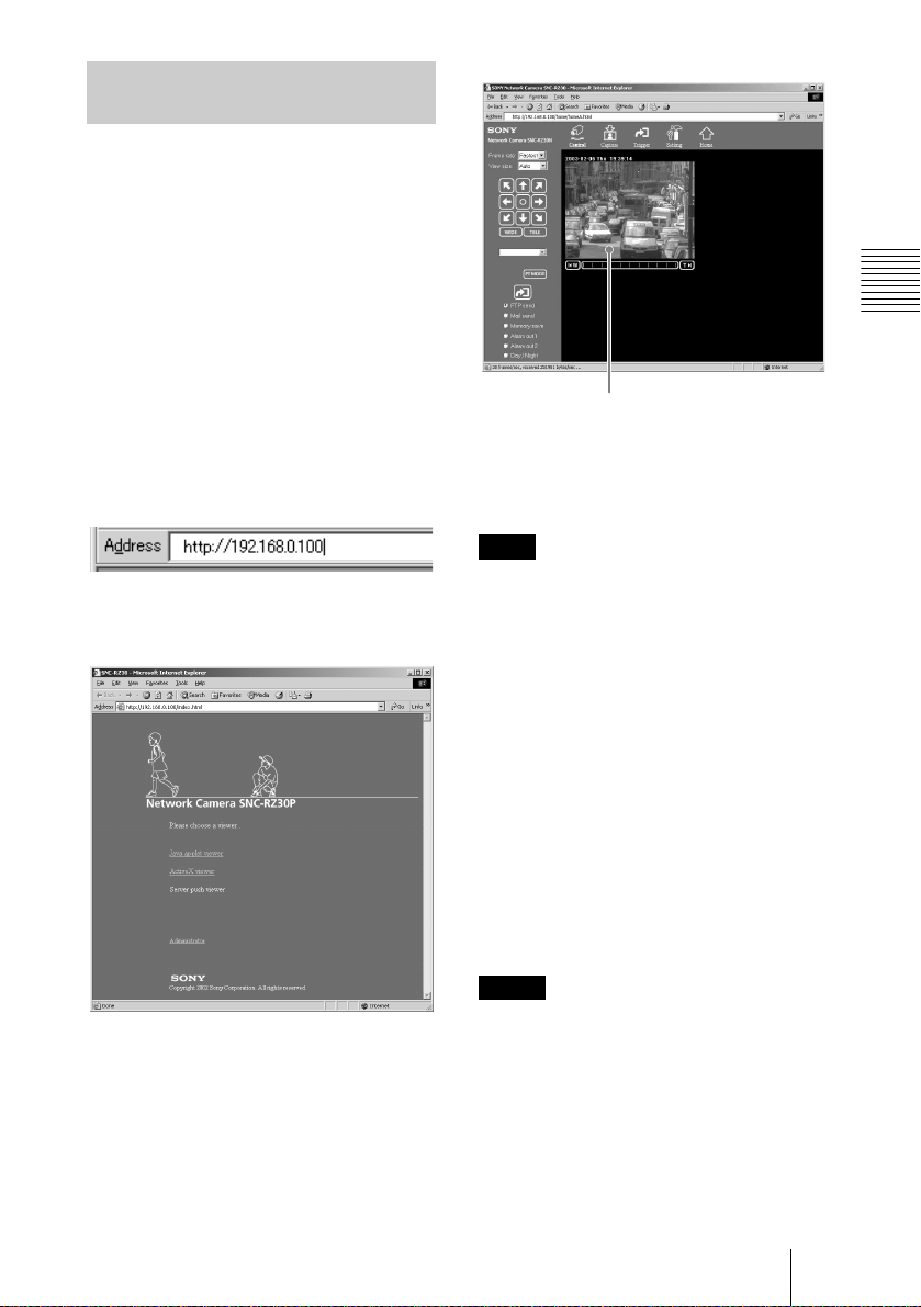
1 Start the Web browser on the
computer and type the IP
address of the camera in the
URL box.
The Welcome page of Network
Camera SNC-RZ30 is displayed.
Basic Installation and Connections
Monitor image
Now the IP address assignment is
completed.
Proceed to “Installing the Camera.”
Note
To operate the welcome page correctly, set
the security level of the Internet Explorer to
Medium or lower, as follows:
1 Select Tool from the menu bar of
Internet Explorer, then select Internet
Options and Security tab in
sequence.
2 Click the Internet icon (when using
the camera via the Internet) or Local
intranet icon (when using the camera
via a local network).
3 Set the slider to Medium or lower. (If
the slider is not displayed, click
Default Level.)
2 Click ActiveX viewer.
The Main Viewer page is displayed and
the monitor image from the camera
appears on the screen.
When you display the monitor image
from the camera for the first time, the
Security Warning appears. Click Yes
and install the ActiveX Control.
Notes
• When you install ActiveX viewer on
Windows NT4.0, Windows 2000 or
Windows XP, you should have logged in
the computer as the Administrator.
• If you cannot display the image on
Windows NT4.0 or Windows 98, install
MFC42DLL Version Up Tool stored in
the supplied CD-ROM.
• If Automatic configuration is enabled in
the Local Area Network (LAN) Settings
Assigning the IP Address to the Camera
15
GB

on Internet Explorer, the image may not be
displayed. In this case, disable Automatic
configuration and set the Proxy server
manually. For setting the Proxy server,
consult your network administrator.
• The page may not be displayed correctly if
you use antivirus software in your
computer.
Installing the
Camera
ATTENTION
If installing the camera on the ceiling, be
sure it is secure. If not securely installed, the
camera may fall and injury may occur.
Note on the installation angle
The camera installation angle within ±15°
from the horizontal line is guaranteed. If the
camera is installed over the guaranteed
angle, it cannot be operated correctly.
Note on handling of the pan/tilt
mechanism of the camera
To prevent damage, do not apply excessive
force to the pan/tilt mechanism of the
camera or place an obstacle against it. If the
pan/tilt operation is affected by the
excessive force, turn off the power of the
camera and turn it on again. If the problem
still persists, consult your authorized Sony
dealer.
Note on use of the supplied
accessories
To secure the ceiling bracket and the wire
rope to the camera, use the supplied four
screws and the shoulder screw only. Use of
other screws may cause improper mounting
and damage parts inside the camera.
GB
16 Installing the Camera
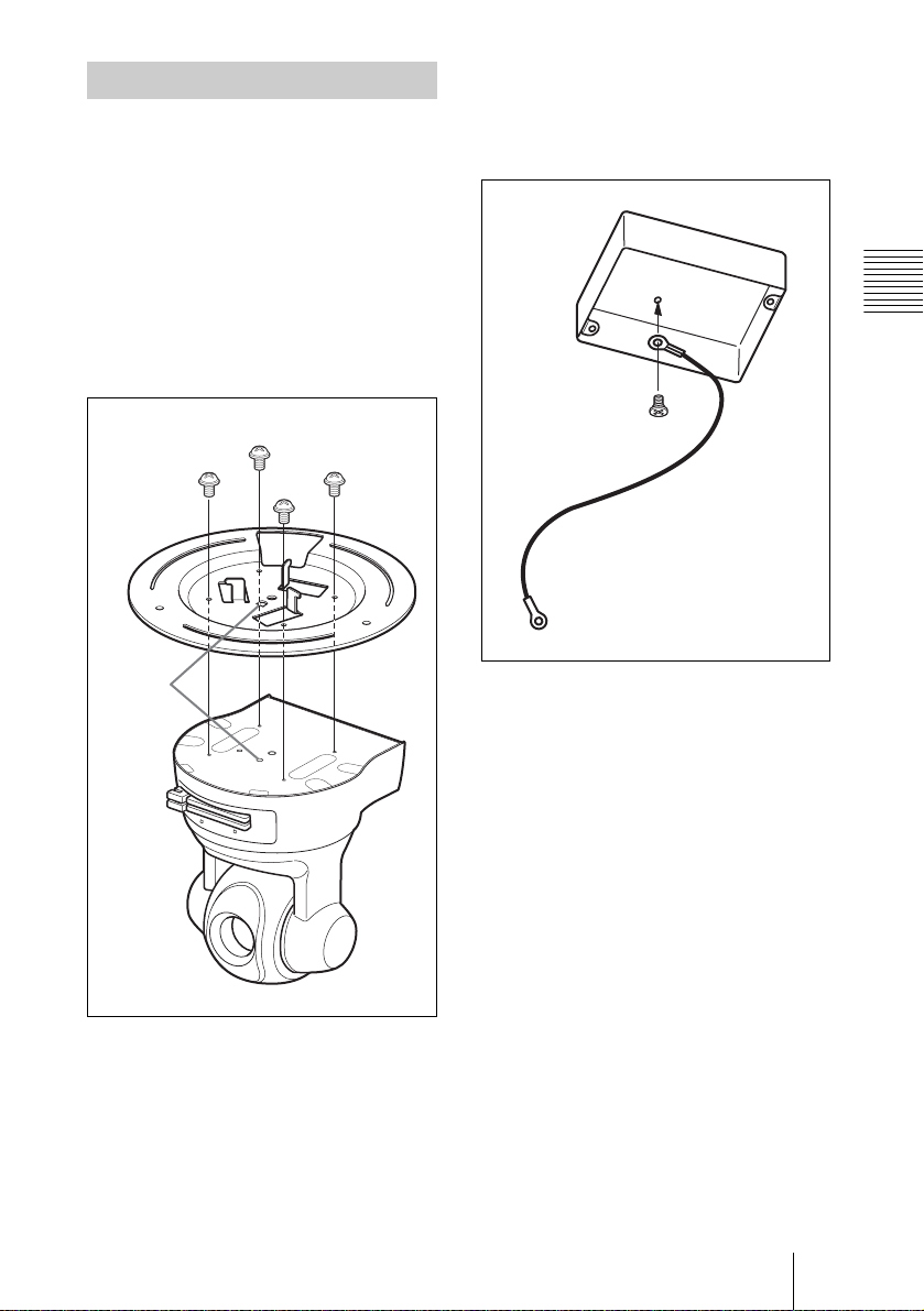
Installing on the Ceiling
You can install the camera to a junction box
pre-installed on the ceiling using the
supplied ceiling brackets, wire rope and
screws.
1 Mount the ceiling bracket (A) to
the bottom of the camera using
the supplied four screws (+M 3 ×
6).
Hook the projection on the bracket to the
hole on the camera.
+M 3 × 6 (supplied)
Hook the
projection
to the hole.
2 Secure the wire rope to the
junction box on the ceiling.
Use a screw to match the screw hole of
your junction box (not supplied).
Basic Installation and Connections
Installing the Camera
17
GB

3 Mount the ceiling bracket (B) to
the junction box on the ceiling.
Use screws to match the screw holes of
your junction box (not supplied).
Use the appropriate screw holes on the
bracket so that one of the three
projections on the circumference of the
bracket indicates the direction in which
the front of the camera will face.
Front of
the camera
4 Secure the wire rope to the wire
rope mounting screw hole on
the bottom of the camera using
the supplied shoulder screw.
Shoulder
screw
(supplied)
GB
Installing the Camera
18
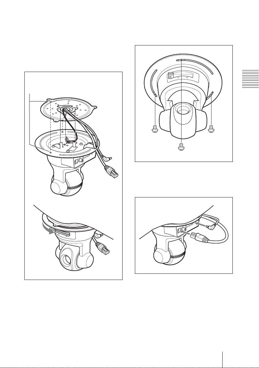
5 Insert the three projections on
the ceiling bracket (A) to the
holes on the ceiling bracket (B),
then turn the bracket (A)
clockwise to fix it temporarily.
Pass the cables through the hole on the
bracket (A) as illustrated.
Aligning these two holes
guides insertion.
6 Secure the brackets (A) to (B)
using the supplied screws (+M 3
× 6).
Basic Installation and Connections
+M 3 × 6
(supplied)
7 Connect the cables to the
connectors on the rear of the
camera.
Installing the Camera
19
GB
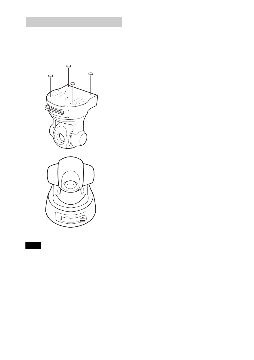
Installing on the Desk Top
Stick the supplied four rubber feet on the
bottom of the camera, and place the camera
on the desk top.
Rubber feet
(supplied)
Note
By default, the images from the camera are
displayed normally when the camera is
installed on the ceiling. To display the
images from the camera in correct way when
you place the camera on the desk top, use the
image flip function.
For the setting of the image flip function, see
the User’s Guide stored in the supplied CDROM.
GB
20 Installing the Camera

B Others
Precautions
This Sony product has been designed with
safety in mind. However, if not used
properly electrical products can cause fires
which may lead to serious body injury.
To avoid such accidents, be sure to heed the
following.
Heed the safety precautions
Be sure to follow the general safety
precautions, and the “Operating
Precautions.”
In case of a breakdown
In case of a system breakdown, discontinue
use and contact your authorized Sony dealer.
In case of abnormal operation
• If the unit emits smoke or an unusual
smell,
• If water or other foreign objects enter the
cabinet, or
• If you drop the unit or damage the cabinet:
1 Disconnect the camera cable and the
connecting cables.
2 Contact your authorized Sony dealer or
the store where you purchased the
product.
Operating Precautions
Operating or storage location
Avoid operating or storing the camera in the
following locations:
• Extremely hot or cold places (Operating
temperature: 0°C to +40°C [32°F to
104°F])
• Exposed to direct sunlight for a long time,
or close to heating equipment (e.g., near
heaters)
• Close to sources of strong magnetism
• Close to sources of powerful
electromagnetic radiation, such as radios
or TV transmitters
Transportation
When transporting the camera, repack it as
originally packed at the factory or in
materials of equal quality.
Cleaning
• Use a blower to remove dust from the lens
or optical filter.
• Use a soft, dry cloth to clean the external
surfaces of the camera. Stubborn stains
can be removed using a soft cloth
dampened with a small quantity of
detergent solution, then wipe dry.
• Do not use volatile solvents such as
alcohol, benzene or thinners as they may
damage the surface finishes.
Note on laser beams
Laser beams may damage the CCDs. If you
shoot a scene that includes a laser beam, be
careful not to let a laser beam become
directed into the lens of the camera.
Others
Precautions
21
GB
Typical CCD
Phenomena
About a Memory
Stick
The following phenomena may appear on
the monitor screen while you are using a
CCD color video camera. These phenomena
stem from the high sensitivity of the CCD
image sensors, and do not indicate a fault
within the camera.
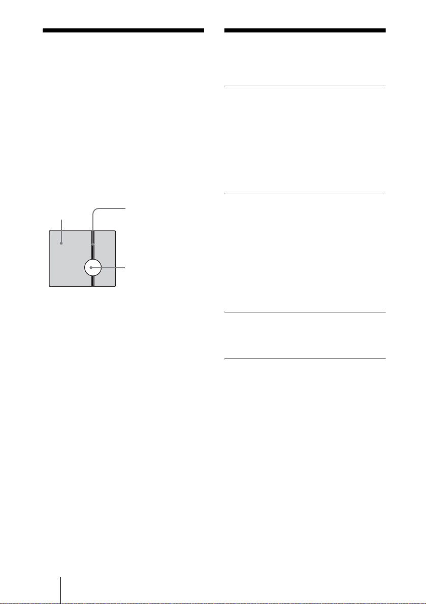
Vertical smear
A “smear” may appear to extend vertically
from very bright subjects, as shown below.
Video monitor
screen
This phenomenon is common to CCD
imaging elements using an interline transfer
system, and is caused when electric charge
induced by infrared radiation deep within
the photo sensor is transferred to the
resistors.
Aliasing
When shooting fine stripes, straight lines or
similar patterns, the lines may become
slightly jagged.
Blemishes
A CCD image sensor consists of an array of
individual picture elements (pixels). A
malfunctioning sensor element will show up
as a single pixel blemish in the image. This
is generally not a problem.
Pale vertical smear
Very bright subject
(such as an electric
lamp, fluorescent
lamp, sunlight, or
strong reflected light)
On Memory Sticks
“Memory Stick“ is a new compact, portable
and versatile IC recording medium with a
data capacity that exceeds a floppy disk.
“Memory Stick” is a specially designed for
exchanging and sharing digital data among
“Memory Stick” compatible products.
Because it is removable, “Memory Stick”
can also be used for external data storage.
Types of Memory Sticks
There are two types of “Memory Sticks”: the
“MagicGate Memory Stick” that is equipped
with the MagicGate copyright protection
technology, and the general “Memory
Stick.” You can use both types of “Memory
Stick” with this unit. However, because this
unit does not support the MagicGate
standards, data recorded with this unit is not
subject to MagicGate copyright protection.
On MagicGate
MagicGate is copyright protection
technology that uses encryption technology.
To protect Memory Stick data
A “Memory Stick” is equipped with a writeprotect tab. You can record or erase data, or
format the “Memory Stick” when you set the
write-protect tab to the left position. If you
set the write-protect tab to LOCK (right
position), you can read data but cannot
record data. When you use a “Memory
Stick” with this unit to read the recorded
images, we recommend that you set the
write-protect tab to LOCK.
White speckles
When you shoot a poorly illuminated object
at a high temperature, small white dots may
appear all over the entire screen image.
GB
22 Typical CCD Phenomena/About a Memory Stick
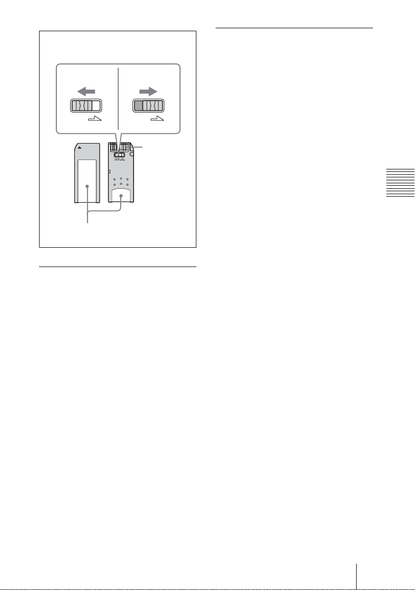
LOCK LOCK
Example
Write-protect tab
Allows
recording
Labeling positions
Prohibits
recording
Terminal
About formatting Memory Sticks
Before using the purchased “Memory Stick”
with this unit, format it using a computer.
Notes on use
• When you use a “Memory Stick” with this
unit, insert a commercially available
“Memory Stick” PC card adaptor to the PC
card slot and insert the “Memory Stick”
into the PC card adaptor.
• Do not remove a “Memory Stick” or turn
off the power of the unit during data
loading. Doing this may damage or erase
the data in the “Memory Stick.”
• Do not bend, drop or apply strong shock to
a “Memory Stick.”
• Do not disassemble or modify a “Memory
Stick.”
• Do not let a “Memory Stick” get wet.
• Do not use or keep a “Memory Stick” in
the locations that are:
— Extremely hot, such as in a car parked
in the sun or outdoors under the
scorching sun.
— Under direct sunlight.
— Very humid or subject to corrosive
gases.
— Near static electricity or magnetic
fields.
• Prevent metallic objects or you finger
from coming into contact with the metal
parts of the connecting section of a
“Memory Stick.”
• Do not attach any material other than the
supplied label onto the labeling position
on the “Memory Stick.”
• When you carry or store a “Memory
Stick,” put it in its case.
Others
. . . . .. . . . . . . . . . . . . . . . . . . . . . . . . . . . . . . . . . . . . . . . . . . . . . . . . . . . . . . . . . . . . . . . . . . . . . . . . . . .
“Memory Stick” and “MagicGate Memory Stick” are trademarks of Sony Corporation.
About a Memory Stick
23
GB

Specifications
System/network
CPU 32-bit RISC processor
RAM 32 MB
Flash memory 8 MB
OS µITRON 3.0 compliant
Protocol TCP/IP, ARP, ICMP, HTTP, FTP
Image size SNC-RZ30N
Compression format
Image quality (compression rate)
Frame rate SNC-RZ30N
Web browser Internet Explorer Ver. 5.5 or 6.0
Computer environments
including the built-in image
memory of about 8 MB
(server/client), SMTP, DHCP
(client), SNMP
× 480 (Auto), 736 × 480
736
(Frame), 736
× 480 (Field), 640
× 480 (Auto), 640 × 480
(Frame), 640
× 480 (Field), 320
× 240, 160 × 120
SNC-RZ30P
× 544 (Auto), 736 × 544
736
(Frame), 736
× 544 (Field), 640
× 480 (Auto), 640 × 480
(Frame), 640
× 480 (Field), 320
× 240, 160 × 120
JPEG, baseline compliant
(YCbCr422)
Approx. 1/5 to 1/60 (10 steps)
The compression rate is based on
an image of 24 bits/picture
element (8 bits for each R, G
and B).
Max. 30 FPS (640
SNC-RZ30P
Max. 25 FPS (640
(Available OS: Windows 98/
98SE/ Me/ NT4.0/ 2000/ XP)
Netscape Navigator Ver. 6.2x
(Available OS: Windows 98/
98SE/ Me/ NT4.0/ 2000/ XP)
Pocket PC Internet Explorer
(Available OS: Pocket PC
2002)
Windows
CPU: Pentium III 500 MHz or
higher (Pentium 4, 1 GHz or
higher recommended)
RAM: 128 MB or more
Display size: 1024
Color or more
Pocket PC
× 480)
× 480)
× 768, True
CPU: Strong ARM 206 MHz or
higher, or compatible CPUs
RAM: 64 MB or more
Plug-in: Jeode
Maximum user access
50 users
Network security
Password (basic authentication),
IP filtering
Homepage customization
Starting from a homepage in a PC
card is possible.
Other functions
Activity detection, image
trimming, built-in clock, etc.
1) Jeode is a registered trademark or trademark of
Insignia Solutions, Inc. in the United States and
other countries.
1)
Ver. 1.9.1
Camera
Image device SNC-RZ30N
Signal-to-noise ratio
Minimum illumination
Exposure mode
Iris Auto/Manual (F1.6 to Close)
Gain Auto/Manual (
Electronic shutter
White balance mode
Focus mode Auto/Manual (Near, Far, One Push
Zoom mode Full (×1 to ×300), Optical only (×1
Saturation adjustment
1/6 type CCD, interlin e transfer,
680,000 picture elements
SNC-RZ30P
1/6 type CCD, interlin e transfer,
800,000 picture elements
48 dB
2.5 lx (AE mode, slow shutter off)
Auto, Shutter-priority, Iris-
priority, Manual (Backlight
compensation is switchable
except in Manual mode.)
–3 dB to 28 dB)
Auto/Manual (1 to 1/10,000 sec.)
Auto, Indoor, Outdoor, One Push
White Balance, ATW, Manual
Auto Focus)
to ×25)
–3 to +3
Sharpness adjustment
Contrast adjustment
1 to 16
–3 to +3
Other functions
Day/Night function, Stabilizer,
Exposure compensation, Image
flip function
GB
24 Specifications

Lens
Zoom ratio ×25 (infinite)
Horizontal view angle
Focal length f = 2.4 mm to 60 mm
F number F1.6 (Wide end), F2.7 (Tele end)
Minimum shooting distance
2) The wide end is set to about 300 mm at the factory.
For setting it to 35 mm, consult your authorized
Sony dealer.
2.0° to 45°
Tele end: 800 mm
Wide end: 35 mm
2)
Mechanism
Pan –170° to +170°, 340° rotation
Tilt
within 2 seconds
–90° to +25°, 115° rotation within
1.5 seconds
Interface
Ethernet port 10BASE-T/100BASE-TX (RJ-45)
I/O port Alarm input 1 to 3: 3.3 to 24 V DC
Serial interface
Video output VIDEO OUT: BNC, 1.0 Vp-p,
PC card slot PCMCIA Type II (2)
device supported
(photo coupler inputs
electrically isolated from the
camera)
Alarm output 1 and 2: 24 V DC or
less, 1 A
(mechanical relay outputs
electrically isolated from the
camera)
Transparency type RS-485/RS-
232C
75 ohms, unbalanced, sync
negative
Supplied accessories
AC power adaptor (1)
AC power cord (1)
CD-ROM (setup program and
User’s Guide) (1)
Ceiling bracket (A) (1)
Ceiling bracket (B) (1)
Wire rope (1)
Fixing screws (+PSW 3 × 6) (7)
Shoulder screw M4 (1)
I/O receptacle (1)
Rubber foot (4)
Clamp filter (2)
Installation Manual (this
document) (1)
Optional Accessories
“Memory Stick” MSH-128 (128 MB)
“Memory Stick” PC card adaptor MSACPC3
Design and specifications are subject to
change without notice.
Regular parts replacement
Some of the parts that make up this
product (electrolytic condenser, for
example) need replacing regularly
depending on their life expectancies.
The lives of parts differ according to the
environment or condition in which this
product is used and the length of time it is
used, so we recommend regular checks.
Consult the dealer from whom you bought
it for details.
Others
Others
Power supply 12 V DC
Current consumption
Power consumption
Operating temperature
Storage temperature
Dimensions 140 × 175 × 144 mm (5
Mass Approx. 1.2 kg (2 lb 10 oz)
1.8 A max. (at 12 V DC)
21.6 W max.
0 °C to 40 °C (32 °F to 104 °F)
–20 °C to 60 °C (–4 °F to 140 °F)
3
/4 inches)
not including the projecting parts
5
/8 × 7 × 5
Specifications
25
GB
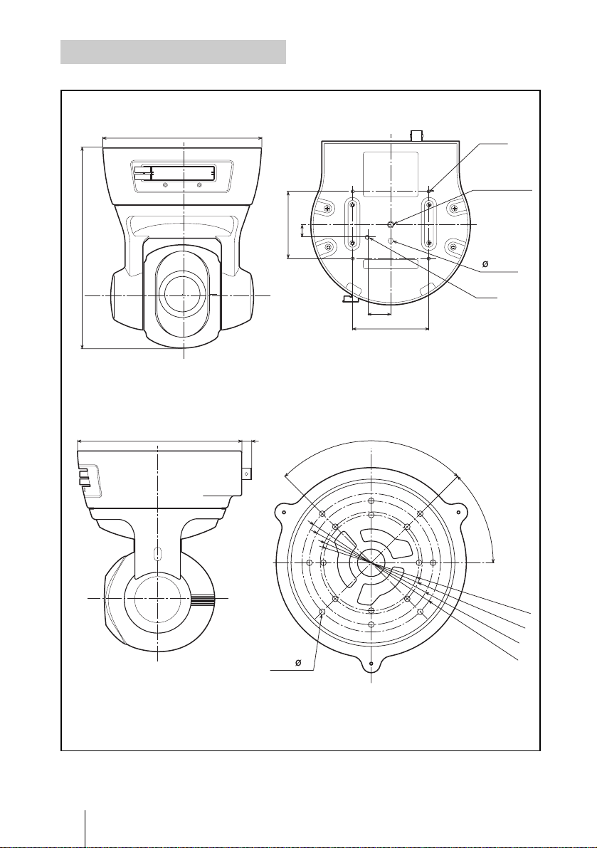
Dimensions
Front
175
Side
144
140
Bottom
±0.2
±0.2
11
60
Ceiling bracket (B)
8.5
90˚
21
70
4-M3
tripod screw
hole
1/4-20UNC
(ISO1222)
5
M4
±0.2
±0.2
45˚
GB
26 Specifications
16 – 5
ø83.5
ø88.9
ø108
ø120.8
Unit: mm
±0.2
±0.2
±0.2
±0.2
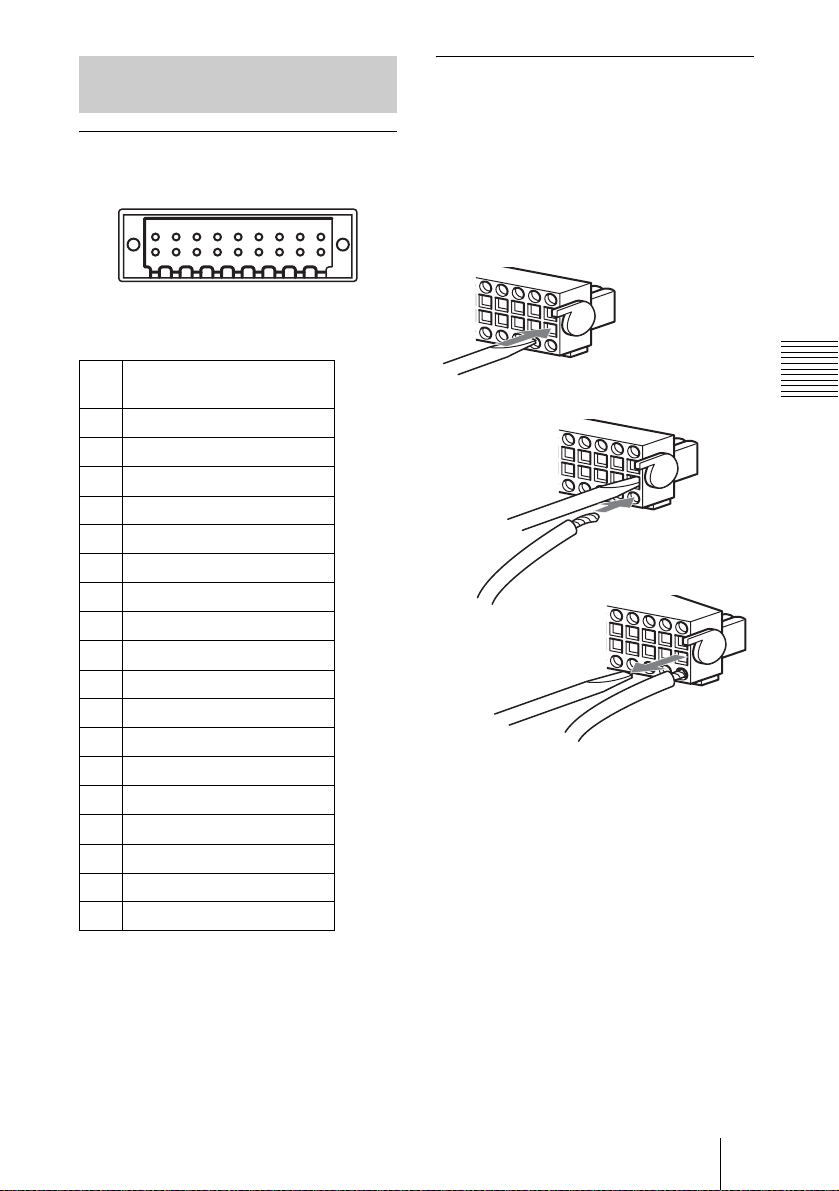
Pin Assignment and Use of
I/O Port
Pin assignment of I/O port
24681012141618
1357911131517
I/O
Using the I/O receptacle
1 Insert a small slotted screwdriver into
the upper or lower slot of the hole you
want to connect a wire to (AWG No.
28 to 18). Hold down the screwdriver
and insert the wire, then release the
screwdriver.
1
Pin
Pin name
No.
1 Sensor In 1 –
2 Sensor In 1 +
3 Sensor In 2 –
4 Sensor In 2 +
5 Sensor In 3 –
6 Sensor In 3 +
7 Alarm Out 1 –
8 Alarm Out 1 +
9 Alarm Out 2 –
10 Alarm Out 2 +
11 GND
12 VDD (5 V)
13 GND (RS-232C/485)
14 Reserved
15 RXD (RS-232C)
16 TXD (RS-232C)
17 – TXD/RXD (RS-485)
18 + TXD/RXD (RS-485)
Slotted screwdriver
Others
2
Wire
3
Repeat this procedure to connect all
required wires.
2 Insert the I/O receptacle into the I/O
port on the rear of the camera, and
press upward the levers on both sides
to lock the receptacle.
Specifications
27
GB
 Loading...