

Sony IPELA NSRE-S200 Installation Manual
Expansion
Storage
4-130-097-02 (1)
Unit
Installation Manual ________ GB
設置説明書 JP
Manuel d’installation_______ FR
Installationsanleitung ______ DE
Manuale all’installazione ___ IT
Manual de instalación _____ ES
_________________ CS
NSRE-S200
© 2008 Sony Corporation
Table of Contents
Usage Precautions ................................................. 3
Overview ................................................................ 4
Package Contents .................................................. 5
Features and Functions ......................................... 6
Front (When the Cover is Opened) .................... 6
Rear .................................................................... 7
Reference Data for Installation ............................ 8
Current Consumption and Inrush Current .......... 8
Storage Capacity for Recorded Data .................. 8
Installation ............................................................. 8
Installation Without a Rack ................................ 9
Rack Mount Installation ..................................... 9
Connecting the Power Cord ............................. 11
Connecting to the NSR-1000 Series ................ 12
Connecting to Other NSRE-S200 Units ........... 12
Turning On/Off the Unit ..................................... 13
Turning Off the Unit ......................................... 13
Enabling Use with the NSR-1000 Series ............ 13
Miscellaneous ....................................................... 14
STATUS LED ................................................... 14
Troubleshooting ............................................... 15
Specifications ....................................................... 15
NSRE-S200 ...................................................... 15
Trademarks
• “IPELA” and are trademarks of Sony Corporation.
• Other products or system names appearing in this document are trademarks or registered trademarks of their respective owners.
Further, the ® or ™ symbols are not used in the text.
• Reproduction or duplication, in whole or part, of the software or operation
manual supplied with the recorder, as well as renting or leasing of the
software without the authorization of the right holder is prohibited under
copyright law.
• Sony assumes no responsibility for damages, loss of income, or any
claims from a third party arising out of use of the recorder or supplied software.
• For complete terms and conditions of the warranty for the recorder, refer
to the warranty card included in the package.
• The software supplied with the recorder cannot be used with any other
recorders.
• It is not possible to install any software into the equipment other than the
software supplied by Sony specifically for use with the equipment.
• Note that the specifications of the recorder and supplied software are
subject to change for improvement without prior notice.
Disclaimer of liability for recorded content
Sony Corporation does not accept any liability whatsoever for any problems
arising from a failure to record, or from damage or erasure of recorded content on this equipment, for any reason. This includes claims for compensation of recorded content, and for any concomitant and consequential
damages. Sony Co rporation will not repair, restore, or duplicate any recorded
content. Your use of this product is subject to these conditions.
Before reading this manual
Be sure to read the “Safety Regulations” supplement.
2
Table of Contents
Usage Precautions
Important Information About Safety
• Be sure to connect the unit to a power source that
conforms fully to the electrical specifications of this
unit.
• Use only the supplied power cord. Do not coil the
power cord or bundle it with other cords. Do not piggy
back connections. If current ratings are exceeded,
there is a risk of fire and other accidents.
• Make sure that all AC outlets and power cords are
properly grounded.
• Do not use the unit with the cover or case opened or
removed. Otherwise there is a risk of fire and electric
shock. Do not attempt to open or remove the cover or
case yourself. Always consult your supplier if opening
is necessary.
Important Information About Installation
Locations for use/storage
To prolong the life of the product, avoid use or storage
in the following locations.
• Locations that can become extremely hot or cold. (Be
sure to use the unit that conforms fully to the
specifications of this unit.)
• Locations exposed for an extended time to direct
sunlight, and locations near heating appliances. (Note
that the temperature in a closed car in summer can
exceed +50 ºC/+122 ºF.)
• Locations with high levels of humidity or dust
• Locations subject to strong vibrations
• Locations subject to strong magnetic fields
• Locations in the vicinity of radio or TV transmitters
creating a strong magnetic field
Do not block the ventilation openings
• The ventilation openings on the sides of the unit serve
to prevent internal heat buildup. Always leave a
clearance of at least 10 cm (4 inches) on both sides as
well as behind and above the unit.
• Do not use the unit in a closed box or other enclosure.
• Make sure that there are no cables or other objects in
the vicinity of the fan opening on the rear of the unit.
If the opening is blocked, internal heat buildup can
occur, leading to the risk of fire and damage.
• Also when the unit is installed in a rack, you must
make sure that the fan opening on the rear as well as
the ventilation openings on the front are not blocked
by cables or other objects. Do not install the unit in an
environment where the above requirements cannot be
met.
Use the unit in a horizontal position
• The unit is designed to be operated in a horizontal
position.
• Do not install the unit on a slanted surface, and protect
the unit from shocks.
• When the unit is dropped or otherwise subject to
strong shocks, it can be seriously damaged.
• When installing the unit in a rack, make sure that a
horizontal position is maintained. If the unit is not
properly levelled, malfunction may occur. Also, it is
highly recommended to properly anchor the rack to a
wall or similar, so that it cannot topple over.
Maintenance
• Before cleaning the unit or performing any other kind
of maintenance, be sure to disconnect the power cord
from the AC outlet.
• For cleaning, lightly wipe the cabinet and panels with
a dry cloth. To remove stubborn stains, lightly moisten
the cloth with a mild, neutral detergent and wipe with
a dry cloth afterwards.
• Do not use cleaning alcohol, solvents, benzine,
insecticide, or any other volatile substances, because
these may damage the finish and lead to discoloration.
• Dust can accumulate in the ventilation openings on the
front of the unit. When removing the dust, make sure
that you do not subject the unit to shocks or vibrations.
Transport
Use the original packing material or similar packing to
protect the unit from shocks.
Precautions for Products With Built-in
HDD
This unit has a built-in hard disk drive (HDD). The HDD
is a precision device. If subject to shock, vibration, static
electricity, high temperature or humidity, data loss can
occur. When installing and using the unit, closely
observe the following precautions.
Protect from shocks and vibrations
When subject to shocks or vibrations, the HDD can be
damaged and loss of data on the HDD can occur.
• When transporting the unit, use the specified packing
material. When transporting on a dolly or similar, use
a type which does not transmit excessive vibrations.
Excessive shocks and vibrations can damage the
HDD.
• Never move the unit while it is powered. Also before
removing or inserting the unit in a rack, make sure that
power is off.
• Protect all HDD-equipped devices in the rack from
shocks.
• Before removing or inserting the unit in a rack, make
sure that power to any other HDD-equipped devices in
the rack is also switched off.
• Do not remove panels or outer parts of the unit.
GB
Usage Precautions
3
• When placing the unit on a floor or other surface,
make sure that the unit is equipped with the specified
rubber feet, and put the unit down carefully. If there
are no feet, mount the rubber feet first.
Do not place the unit near other devices that may
become a source of vibrations.
Wait for 30 seconds after turning power off
For a brief interval after the power is turned off, the
platters inside the HDD will still keep spinning and the
heads will be in an insecure position. During this
interval, the unit is more susceptible to shocks and
vibrations than during normal operation. For a period of
at least 30 seconds after turning power off, avoid
subjecting the unit even to very light shocks. After this
period, the hard disk will be fully stopped and the unit
can be manipulated.
Temperature and humidity related precautions
Use and store the unit only in locations where the
specified temperature and humidity ranges are not
exceeded. (Be sure to use the unit that conforms fully to
the specifications of this unit.)
When HDD seems to be faulty
Even if the HDD is showing signs of malfunction, be
sure to observe all the above precautions. This will
prevent further damage from occurring until the problem
can be diagnosed and corrected.
Replacement of the HDD and other consumable
parts
The HDD, fan, and battery of the unit are consumable
parts that will need periodic replacement. When
operating at room temperature, a normal replacement
cycle will be about two to three years. However, this
replacement cycle represents only a general guideline
and does not imply that the life expectancy of these parts
is guaranteed. For details on parts replacement, contact
your dealer.
Overview
The NSRE-S200 is an expansion storage unit designed
for use with the NSR-1200/1100/1050H Sony network
surveillance server (herein referred to as the NSR-1000
series). Up to seven NSRE-S200 units can be connected
to the NSR-1000 series.
Large-capacity hard disks allow recording for
long periods of time
Equipped with large-capacity hard disks, the unit is
capable recording high-quality images for extended
periods of time. For reference examples, see “Reference
Data for Installation” (page 8).
Slim type (2U), space-saving 19-inch rack
mounting model
With the optional rack mounting kit (sold separately),
the unit can be installed in a standard universal pitch EIA
19-inch rack.
High reliability
The NSRE-S200 supports RAID 5
high reliability. The system can continue functioning
even if one of the hard disks develops a malfunction.
1) RAID 5 is a system for dividing and storing data and parity
(error correcting codes) onto more than one hard disk drive.
Although this system allows continued operation should
one of the hard disks malfunction, it does not guarantee
restoration of lost data. In addition, due to high internal
processing loads during reconstruction after you replace
the malfunctioned hard disk, the unit may not be able to
record images at the configured recording rate while
reconstruction is in progress.
Important
This manual only describes how to install the
NSRE-S200 and how to connect to the NSR-1000
series. For details on configurations required for using
this unit, refer to the Installation Manual or User's Guide
for the NSR-1000 series.
1)
and peforms with
4
Overview
Package Contents
Check that the following items are included in this
package:
• NSRE-S200 Expansion Storage Unit (1)
• Mini-SAS cable (1 m) (1)
• Front panel key (2)
• Installation Manual (this document) (1)
• Safety Regulations (1)
• WEEE booklet (1)
• Warranty booklet (1)
• Rubber feet (4)
Notes
• This package may contain additional hardware and/or
documentation for those options.
• Save the boxes and packing materials for future use.
• The rack mounting kit (NSR-RM1) is optional (sold
separately).
Package Contents
5
Features and Functions
678
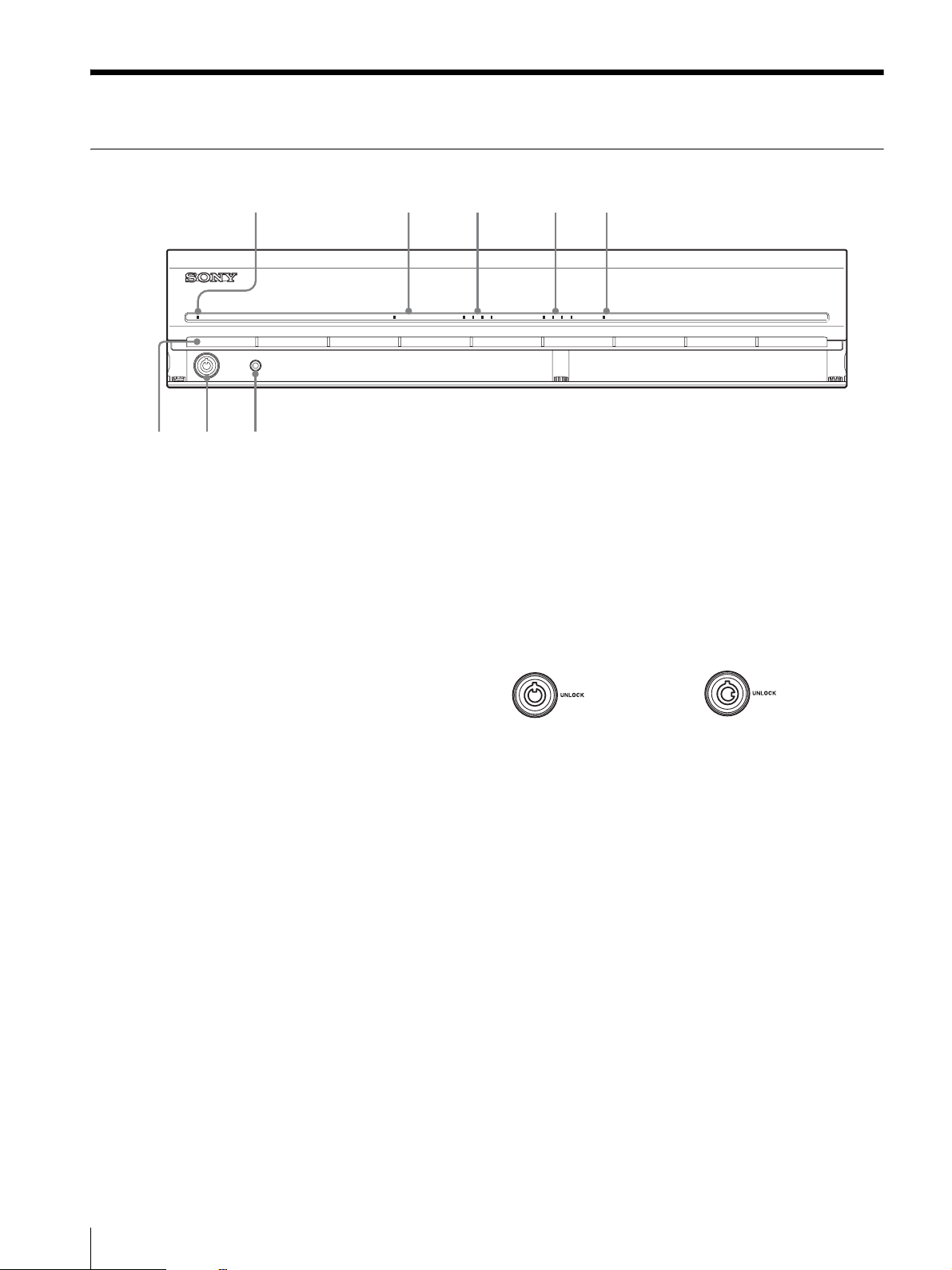
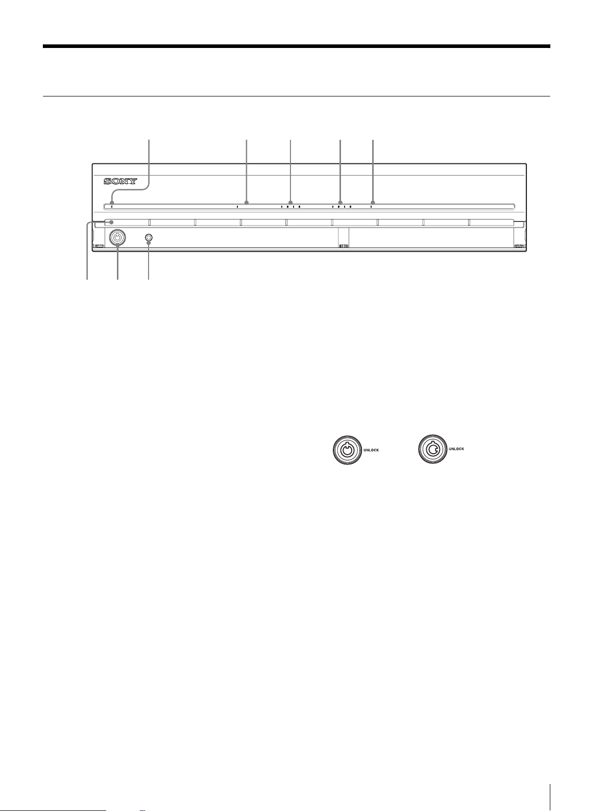
Front (When the Cover is Opened)
12345
POWER NETWORK 1 2 3 4HDD 1 2 3 4 ERRORSTATUS
A Power LED
Lights green when the unit is turned on.
Lights umber when it is on standby.
B Network LED
Lights green when there is activity at the corresponding
LAN connector at the rear of the NSR.
C HDD LED
Blinks green when the internal hard disks are accessed.
Lights amber when an error occurs with a hard disk.
D Status LED (1 to 4)
Lights in sequence (1, 2, 3, 4) when the NSR starts.
When an error occurs, the corresponding status LED
lights together with the error LED, which lights or blinks
to indicate the type of error.
For details, see “STATUS LED” (page 14).
E Error LED
Lights or blinks when an error occurs.
F Power switch
Press this to turn on the unit. (You cannot turn off the
unit with this switch.)
G Lock
Use this in conjunction with the supplied front panel key
to lock the front bezel. When the front bezel is locked,
you cannot pull out the front bezel. Also, do not lock the
front bezel when the front bezel is pulled out. You can
distinguish the locked position from the unlocked
position by looking at the lock, as illustrated below.
The front bezel is
locked
H Vent hol e s
These openings allow air to flow from the front of the
NSR to the rear.
Do not block the vent holes, allow dust to accumulate in
the inner mesh of the vent holes, or obstruct the airflow
in any way. Obstructing the airflow allows heat to build
up inside the unit and may result in fire or damage.
The front bezel is
unlocked
6
Features and Functions
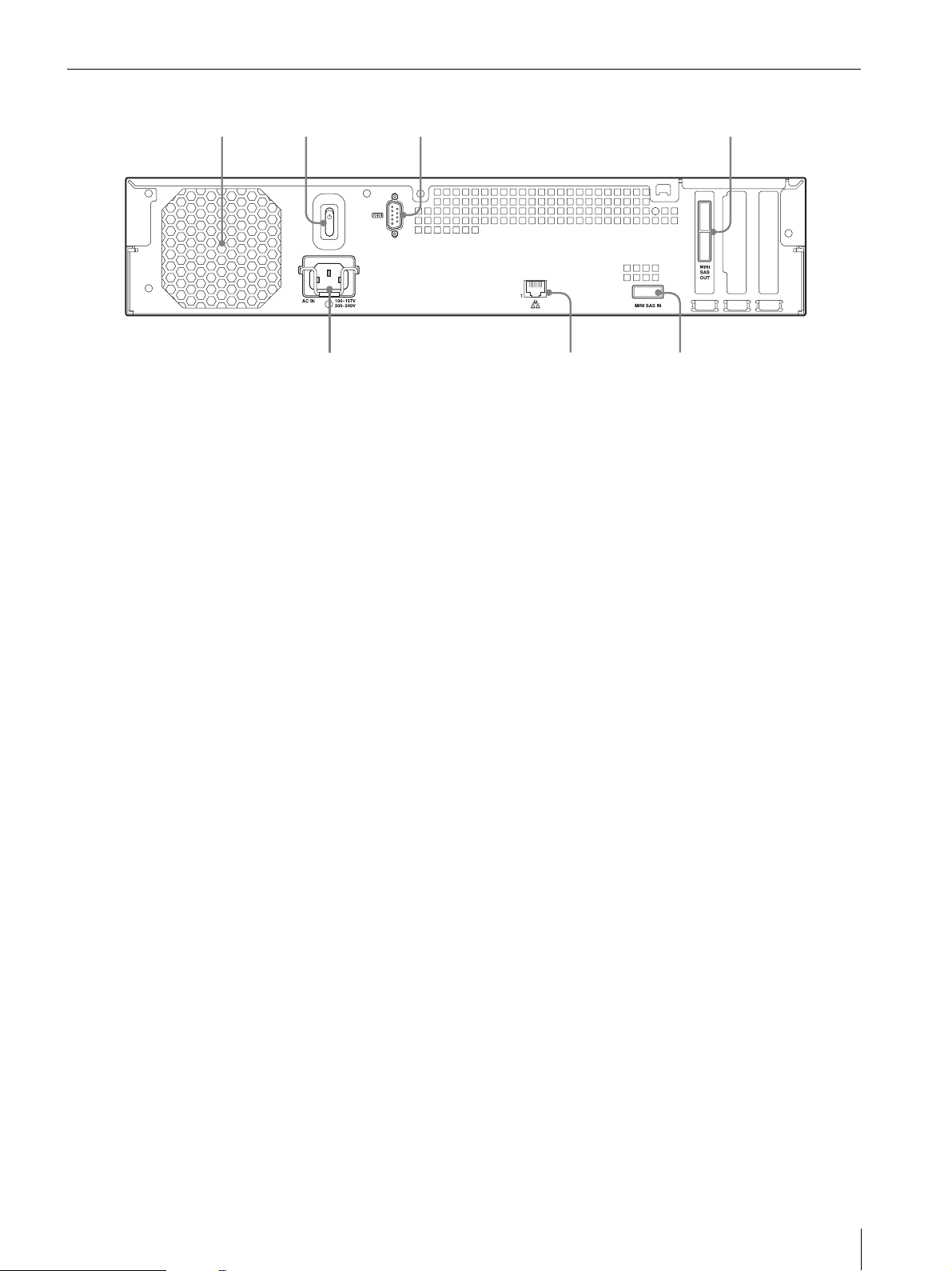
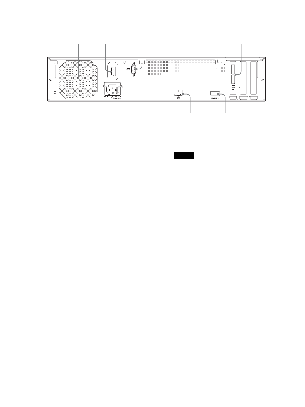
Rear
65
7
231
A Fan
Take care not to obstruct the fan grille. If the grille is
obstructed, heat may build up in the unit, leading to
damage and/or fire.
B Power switch
Press the switch in the 1 position to turn on the unit.
C RS-232C Connector
Used for maintenance.
4
E Mini-SAS input connector
Use this connector to connect the mini-SAS cable used
for connecting an upstream NSR-1000 series unit or
NSRE-S200.
F LAN connector
Used for maintenance.
G Power supply connector
Use this connector to connect the power cord.
D Mini-SAS output connectors × 2
Use this connector to connect the mini-SAS cable used
for connecting a downstream NSRE-S200.
The upper and lower connectors are identical in
function.
Features and Functions
7
Reference Data for
Installation
Installation
Current Consumption and Inrush
Current
Model AC input
voltage
NSRE-S200
100 V 0.8 A
220 V 0.4 A
Storage Capacity for Recorded
Data
The storage capacities for recorded data on the
NSRE-S200 are as follows.
Model Storage capacity
NSRE-S200 1,396 GB
* Data capacities are approximations based on the
following equation for 1 GB: 1,024 × 1,024 × 1,024 =
1,073,740,000 bytes
for recorded data
Full loading Inrush
current
13 A
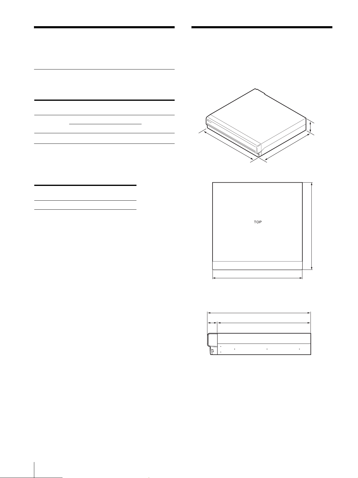
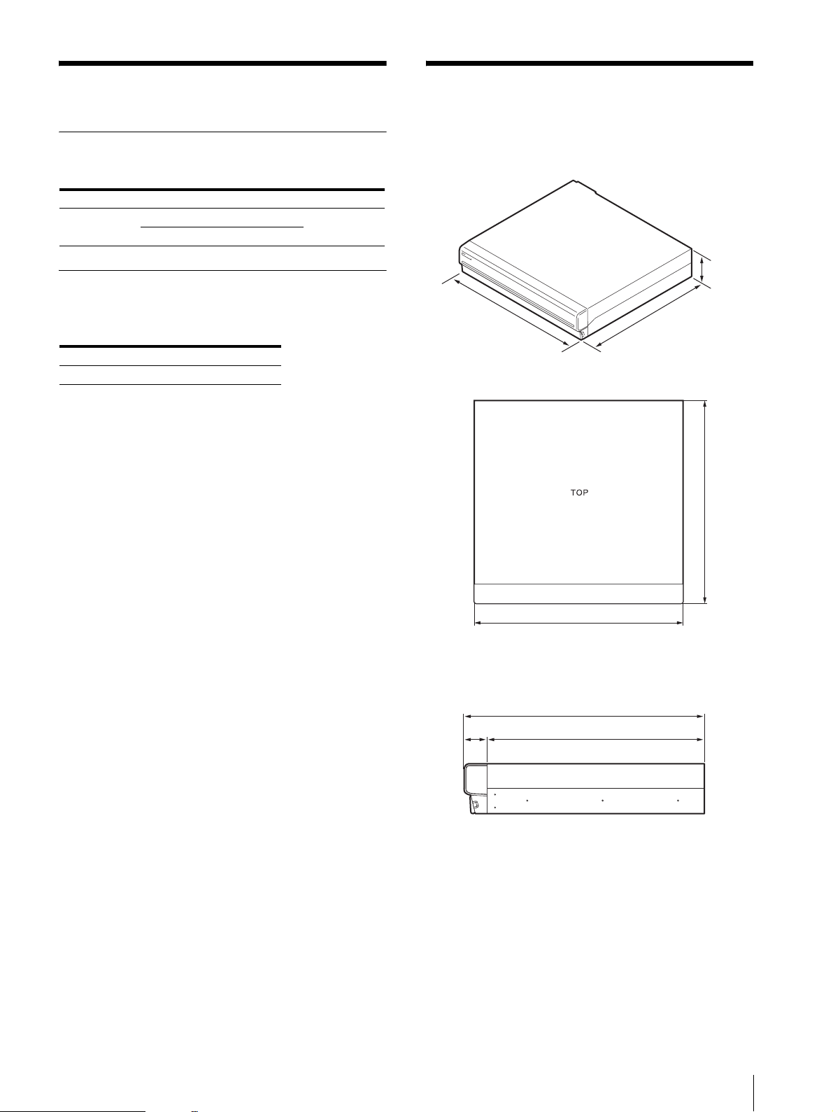
Before setting up, be sure that the location for
installation provides sufficient space and strength to
support the unit.
This unit weighs approx. 12 kg (26.7 lb.). The
dimensions for the unit are as follows.
3.4 in.
(87 mm)
Top
16.9 in.
(430 mm)
16.4 in.
(417 mm)
16.9 in. (430 mm)
When the front bezel is closed
16.4 in. (417 mm)
14.8 in. (377 mm)1.6 in. (40 mm)
16.4 in. (417 mm)
8
Reference Data for Installation / Installation
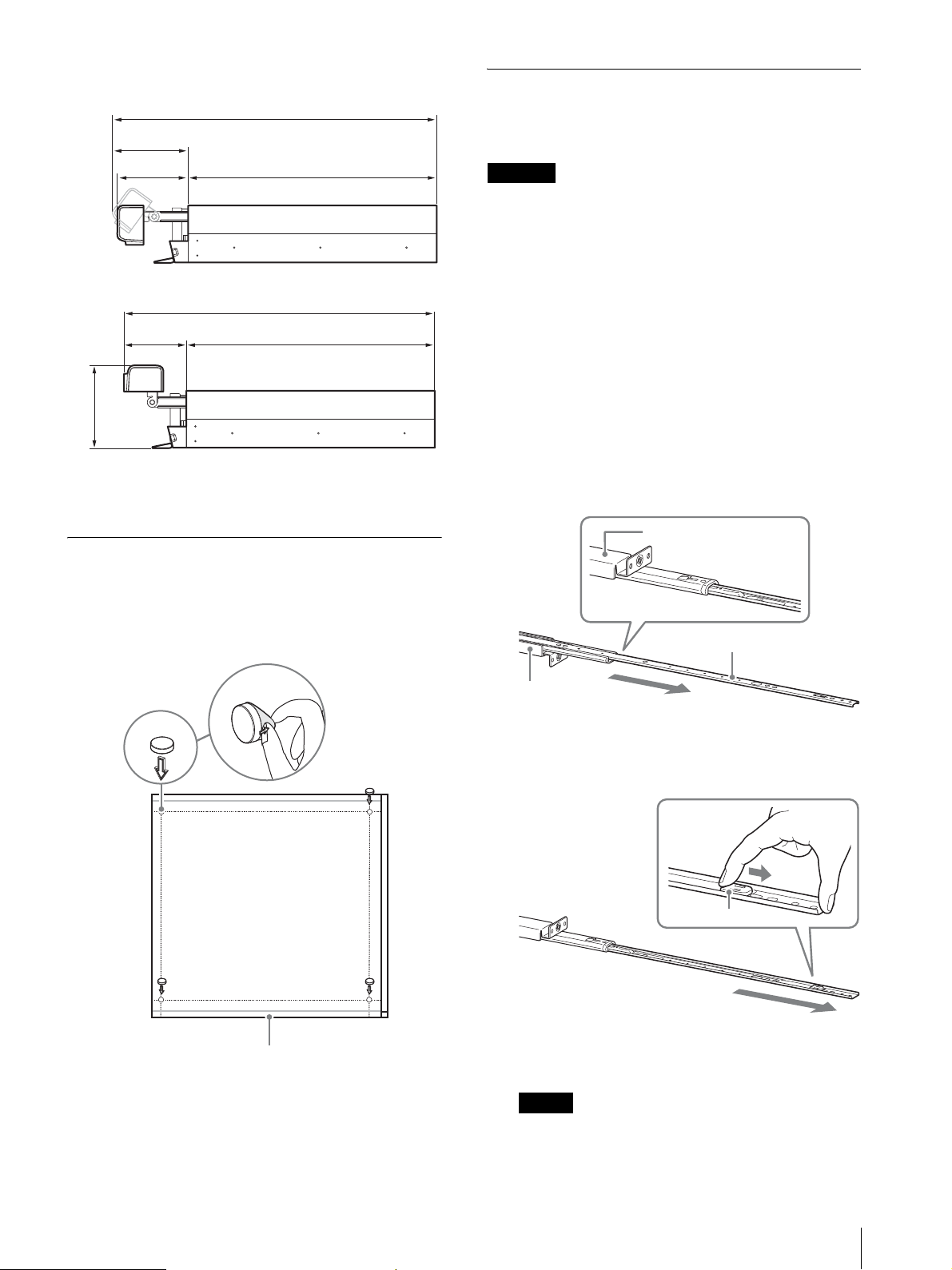
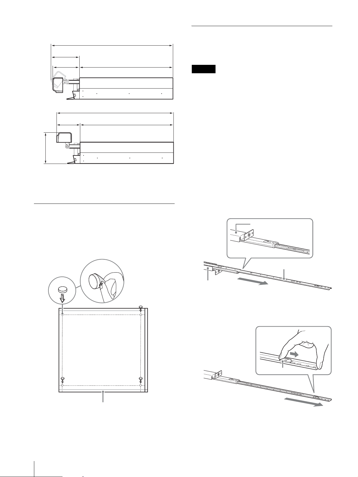
When the front bezel is opened
19.4 in. (494 mm)
4.6 in.
(117 mm)
4.2 in.
(106 mm)
4.0 in.
(102 mm)
14.8 in. (377 mm)
18.9 in. (479 mm)
14.8 in. (377 mm)
Rack Mount Installation
Install the unit in a rack using the optional rack
mounting kit (sold separately).
Warning
• Do not use a rack mounting kit other than the optional
mounting kit (sold separately) for the unit, as doing so
is dangerous and may result in fire, shock, or injury.
• If you mount the unit in a rack, make sure not to place
heavy object on it.
• Before mounting the unit in a rack, we recommend
that you mark its intended position in the rack with a
felt-tip pen. Mounting the unit in the rack other than
horizontally could result in malfunctions.
• To order a rack mounting kit, contact your retailer.
4.8 in.
(123 mm)
You can install the unit on a rack using the optional rack
mounting kit.
Installation Without a Rack
Attach the provided rubber feet to the recorder.
Place the recorder upright so that the bottom surface is
visible. Then affix the adhesive surfaces of the rubber
feet on the bottom of the recorder as illustrated below.
Remove
the film
Rubber
foot
Pulling Out the Inner Rails
Pull out the inner rails from the rail assemblies.
1
Pull out the inner rail from one of the rail
assemblies as far as it can go.
Back of rail assembly
Inner rail
Rail assembly
2
Turn the rail assembly over. As you pull the green
tab outward to release the lock, pull the inner rail all
the way out.
Bottom of the unit
Green tab
3
Repeat the same procedure with the other rail
assembly to pull out its inner rail.
Note
The inner rail will be installed on the unit, while the
rail assembly will be installed on the rack.
Installation
9
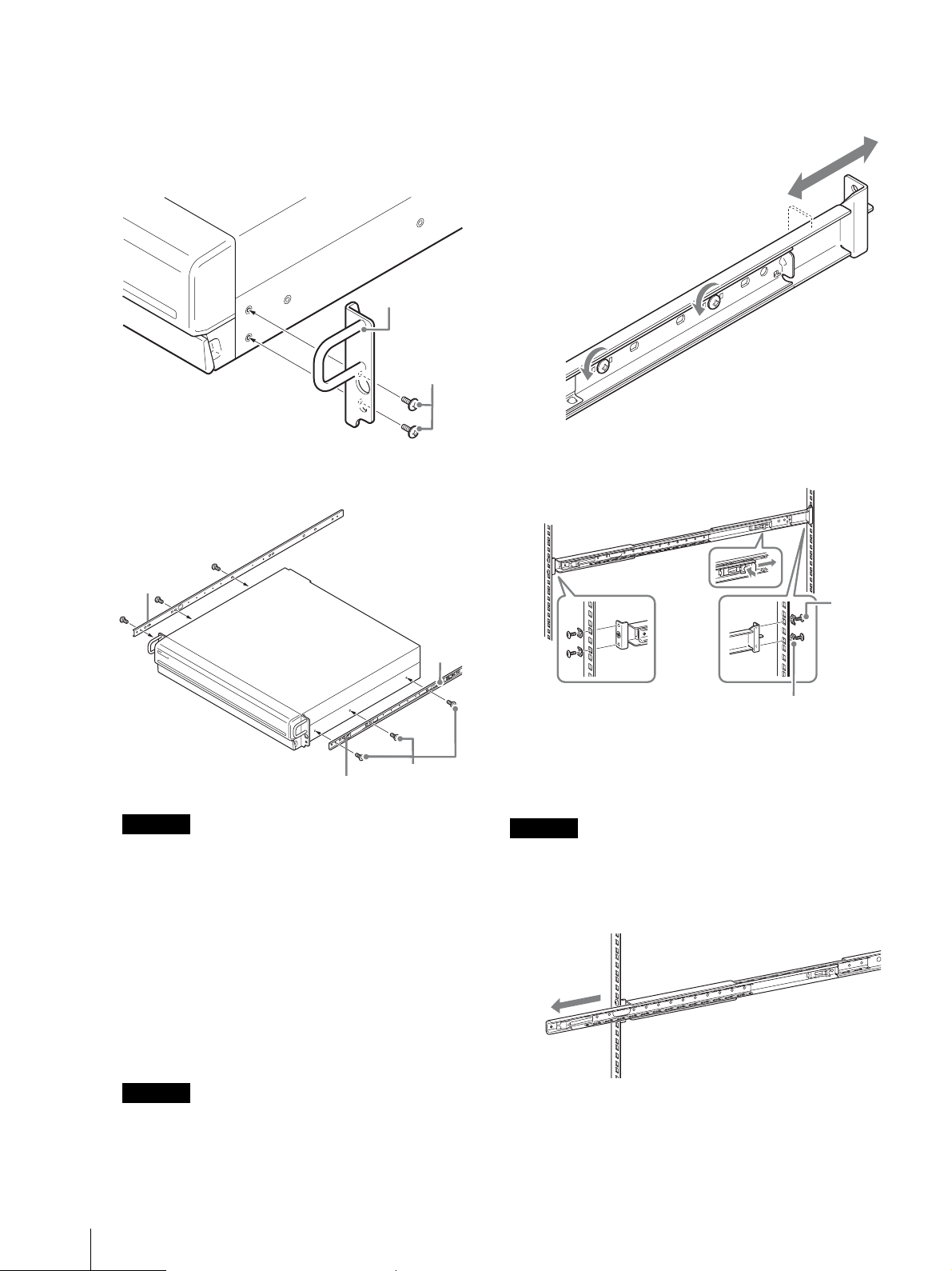
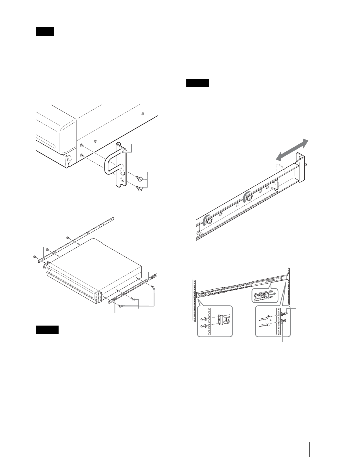
Preparing the Unit
Use the supplied fasteners and screws to install the inner
rail on the unit.
1
Use the supplied flat head screws to attach the
mounting ears to the front of the side panel.
Mounting ear
Flat head
screws
2
Use the remaining supplied round head screws to
install the rails to the unit, as illustrated.
2
Install the rails on the rack.
(1) Adjust the length of the rails to match the length
of your rack.
(2) Use the supplied truss screws and washers to
secure both ends of the rails to the rack.
Green tab
Green tab
Caution
Round head
screws
Using screws other than the supplied screws may
damage the unit. Be sure to use the supplied screws
to install the rails.
Preparing the Rack
Install the rails on the rack.
1
Determine where you want to install the rails on the
rack.
We recommend marking this position with a
marker or felt tip pen.
Rail
Truss
screws
Washers
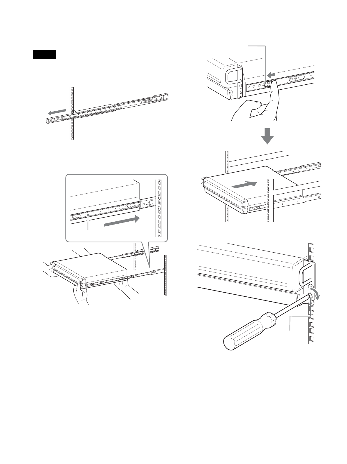
Mounting the Unit on the Rack
Insert the unit into the rack, and then secure it.
Caution
At least two people are needed in order to handle the unit
to prevent personal injury.
1
Pull the sliding rails from the rail assemblies.
10
Caution
Rails installed at different heights could result in
unit malfunctions.
Installation
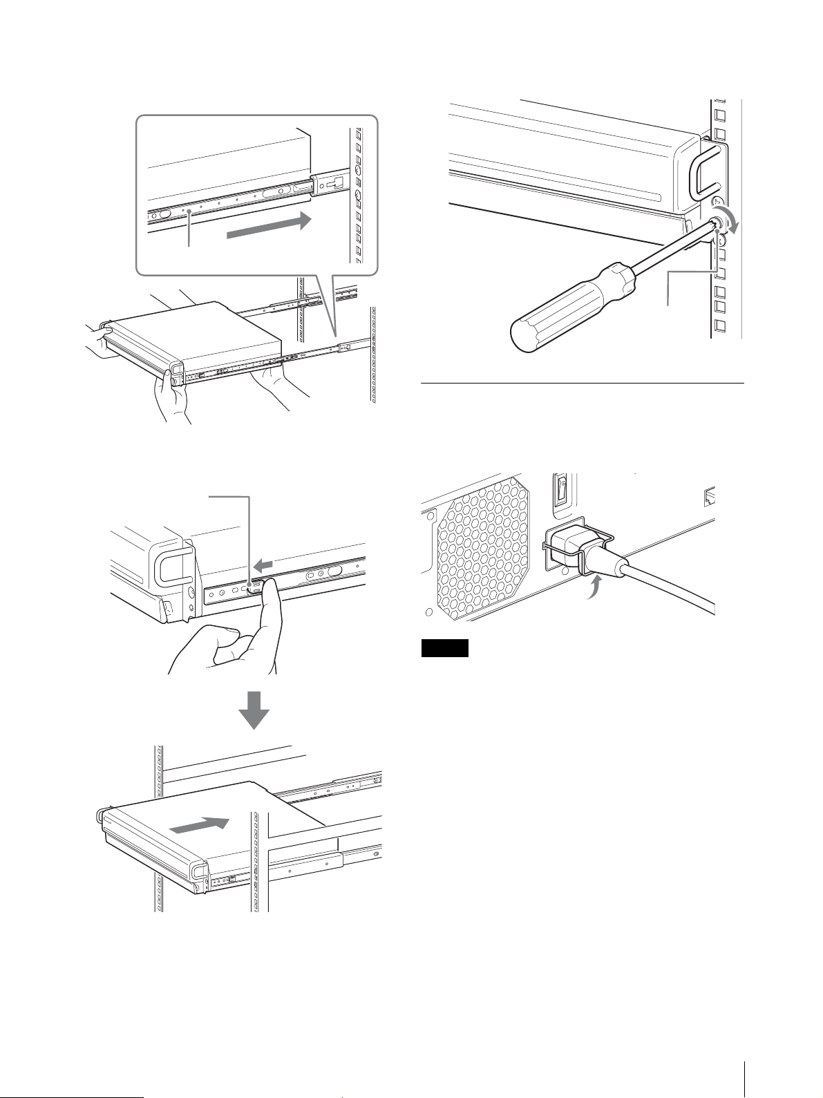
2
Lift the unit, fit the inner rails into the slide rail
grooves (white), and then slide the assembly until it
stops.
Inner rail
3
As you pull the green tab inward to release the lock,
slide the unit as far as it can go.
4
Use the supplied round head screws to secure the
unit to the rack.
Round head
screw
Connecting the Power Cord
Connect the power cord to the power supply connector.
Attach the safety clip to prevent the power cord from
disconnecting.
Green tab
Note
• When using the unit in combination with multiple
NSR-1000 series or other NSRE-S200, make sure that
the power supply is sufficient.
• For details on the current consumption and inrush
current for the NSRE-S200, see “Reference Data for
Installation” (page 8).
Installation
11
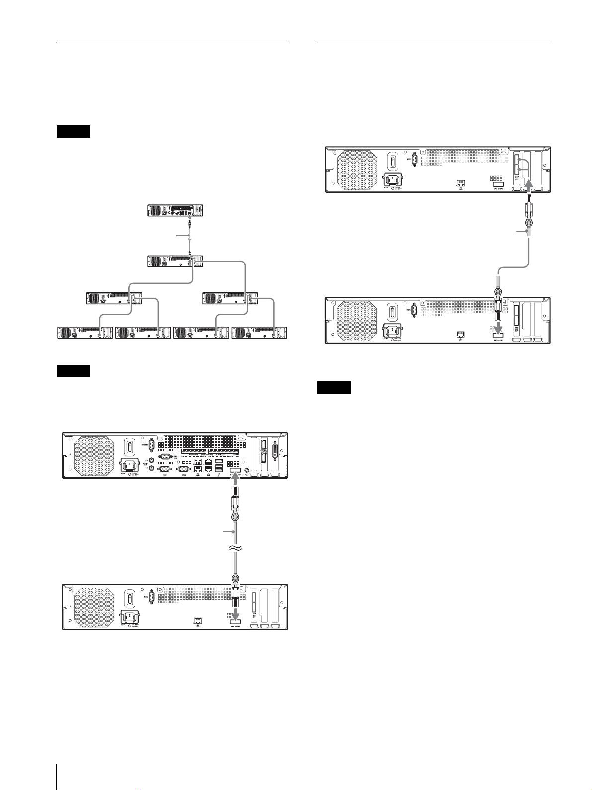
Connecting to the NSR-1000 Series
Connecting to Other NSRE-S200
Use the mini-SAS cable supplied with the NSRE-S200
to connect the NSR-1000 series to the NSRE-S200.
You can connect up to seven NSRE-S200 units to the
NSR-1000 series in a tree configuration as follows.
Note
Units
Use the mini-SAS cable supplied with the NSRE-S200
to connect other NSRE-S200 units upstream and
downstream.
The mini-SAS cable used for connection is supplied
with the NSRE-S200. Be sure to use the supplied cable.
Connect NSRE-S200 expansions in the following order.
NSR-1000 series
Mini-SAS output connector
Mini-SAS cable
NSRE-S200
Mini-SAS input connector
NSRE-S200 NSRE-S200
2
4567
Note
Be sure to connect the NSR-1000 series and the NSRES200 before turning on the power.
NSR-1000 series
1
3
NSRE-S200
Note
The upper and lower mini-SAS output connectors on the
NSRE-S200 are identical in function.
Mini-SAS output
connector
Mini-SAS cable
Mini-SAS input
connector
12
Mini-SAS output
connector
Mini-SAS cable
NSRE-S200
Mini-SAS input
connector
Installation

Turning On/Off the Unit
Enabling Use with the
When you connect the power to the power outlet, the
unit will turn on. After the unit turn off once, pressing
the power switch on the front or rear of the unit, the unit
will turn on.
Wait until the NSRE-S200 has turned on before turning
on NSR-1000 series.
Caution
Take the inrush current into consideration when
configuring power connections for systems that include
multiple NSR-1000 series or an NSRE-S200 unit. For
details on the inrush current, see “Reference Data for
Installation” (page 8).
Front power switch
POWER NETWORK 1 2 3 4HDD 1 2 3 4 ERRORSTATUS
Rear power switch
NSR-1000 Series
Refer to the Installation Manual for the NSR-1000
series, and configure the required settings.
The power LED on the front panel is lit green when the
unit is turned on.
Note
The fan noise may be loud for about 15 seconds after
turning on the unit. This is not a malfunction.
Turning Off the Unit
Perform the following to turn off the unit.
1
Shut down this unit and the NSR-1000 series to
which it is connected.
2
Press the power switch on the rear panel of the unit
in the 1 position for at least 5 seconds.
The unit turns off.
Turning On/Off the Unit / Enabling Use with the NSR-1000 Series
13
Miscellaneous
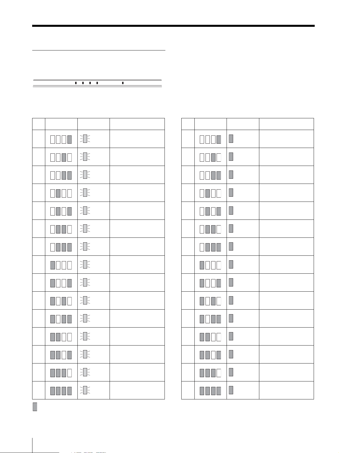
STATUS LED
When an error occurs with the unit, the ERROR LED on the front panel of the unit flashes or lights depending on the
error status, and the STATUS LED lights.
1 2 3 4 ERRORSTATUS
The STATUS LED indicates the following error situations.
Error codes displayed during boot stage
(The ERROR LED blinks when an error occurs
during boot.)
Error
STATUS LED ERROR LED Possible Cause
code
1 Blinking SAS (LSI1068E) failure
1234
2 Blinking COM port failure
1234
3 Blinking H/W monitor chip failure
1234
4 Blinking SAS (LSI1068E) failure
1234
5 Blinking NVRAM failure
1234
6 Blinking
1234
7 Blinking SDRAM failure
1234
8 Blinking Reserved for future use
1234
SDRAM initialization
failure
Error codes displayed during operation stage
(The ERROR LED lights when an error occurs
during operation.)
Error
STATUS LED ERROR LED Possible Cause
code
1 On Critical temperature
1234
2 On Reserved for future use
1234
3 On Power supply fan failure
1234
4 On
1234
5 On Hard disk drive fan 1 failure
1234
6 On Hard disk drive fan 2 failure
1234
7 On CTRL port overheated
1234
8 On Reserved for future use
1234
Voltage power supply
failure
9 Blinking Reserved for future use
1234
A Blinking Reserved for future use
1234
B Blinking Reserved for future use
1234
C Blinking Reserved for future use
1234
D Blinking Reserved for future use
1234
E Blinking Reserved for future use
1234
F Blinking Reserved for future use
1234
indicates that the STATUS LED or ERROR LED is lit.
14
Miscellaneous
9 On Reserved for future use
1234
A On Reserved for future use
1234
B On Reserved for future use
1234
C On Reserved for future use
1234
D On Reserved for future use
1234
E On Reserved for future use
1234
F On Reserved for future use
1234
Troubleshooting
Before contacting your retailer or a Sony Support
Center, please check the following items. If the problem
persists, contact them.
Specifications
NSRE-S200
The unit does not work.
• Verify that the power switch is turned on.
• Verify that the power cable is connected correctly.
• Make sure the wall outlet has power. Test it by
plugging another device.
• Verify that the hard disk drives are not being accessed
(the HDD LEDs on the front of the recorder do not
blink), and then turn it off forcibly by pressing and
holding the power switch at the rear of the unit for
approximately 10 seconds. Restart the unit.
• During the startup procedure, the unit checks the file
system. The length of this check varies depending on
the amount of data on the unit (in some extreme case,
it can take as long as two hours). During the file
system check, the HDD LEDs on the front of the
recorder blink.
Cannot access the hard disk drive.
• Make sure the hard disk drive is properly inserted.
• Check the HDD LEDs on the front panel of the
system. Identify the defective hard disk drive by
reading the drive LEDs. A defective HDD LED lights
umber.
• Due to rapid flashing during frequent access to the
hard disk drive, the HDD LED may appear unlit in
bright environments.
The unit heats up quickly
• Make sure that nothing is blocking the ventilation
openings on the front, sides, and rear of the unit and
dust has not accumulated in them.
Notes
• Always make a test recording, and verify that it was
recorded successfully.
SONY WILL NOT BE LIABLE FOR DAMAGES OF
ANY KIND INCLUDING, BUT NOT LIMITED TO,
COMPENSATION OR REIMBURSEMENT ON
ACCOUNT OF FAILURE OF THIS UNIT OR ITS
RECORDING MEDIA, EXTERNAL STORAGE
SYSTEMS OR ANY OTHER MEDIA OR STORAGE
SYSTEMS TO RECORD CONTENT OF ANY TYPE.
• Always verify that the unit is operating properly before use.
SONY WILL NOT BE LIABLE FOR DAMAGES OF
ANY KIND INCLUDING, BUT NOT LIMITED TO,
COMPENSATION OR REIMBURSEMENT ON
ACCOUNT OF THE LOSS OF PRESENT OR
PROSPECTIVE PROFITS DUE TO FAILURE OF THIS
UNIT, EITHER DURING THE WARRANTY PERIOD OR
AFTER EXPIRATION OF THE WARRANTY, OR FOR
ANY OTHER REASON WHATSOEVER.
Recording devices
Internal hard disk drive
2 TB (SATA-II 500 GB × 4)
Capacities for hard disk drives are based
on the following equation for 1 GB:
1,000 × 1,000 × 1,000 = 1 billion bytes
External connectors
Rear Mini-SAS input (for NSR-1000 series /
NSRE-S200 connection, mini-SAS
(SFF-8088), 3.0 Gbit/s) (1)
Mini-SAS output (for NSRE-S200
connection, mini-SAS (SFF-8088),
3.0 Gbit/s) (2)
Maintenance serial connector: RS-232C (1)
Maintenance LAN connector
(100Base-TX/10Base-T) (RJ-45) (1)
Operating environment
Operating temperature
5 °C to 40 °C (41 °F to 104 °F)
Operating humidity
20% to 80% (maximum wet-bulb
temperature: 30 °C, noncondensing)
Temperature range for storage
–20 °C to +60 °C (–4 °F to +140 °F)
Humidity range for storage
20% to 90% relative humidity (maximum
wet-bulb temperature 35 °C/95 °F, no
condensation)
Power and miscellaneous
Power
100 to 127 V AC/200 to 240 V AC
(50/60 Hz)
Power consumption
Max. 350 W
Dimensions
430 × 87 × 417 mm (16.9 × 3.4 × 16.4 in.)
(W/H/D, excluding protrusions)
Mass
approx. 12 kg (26.7 lb.)
Optional accessories
NSR-RM1 Rack Mounting Kit
Design and specifications are subject to change without
notice.
Specifications
15
安全のために
ソニー製品は安全に充分配慮して設計されています。しかし、電気製品は、まち
がった使いかたをすると、火災や感電などにより死亡や大けがなど人身事故につな
がることがあり、危険です。
事故を防ぐために次のことを必ずお守りください。
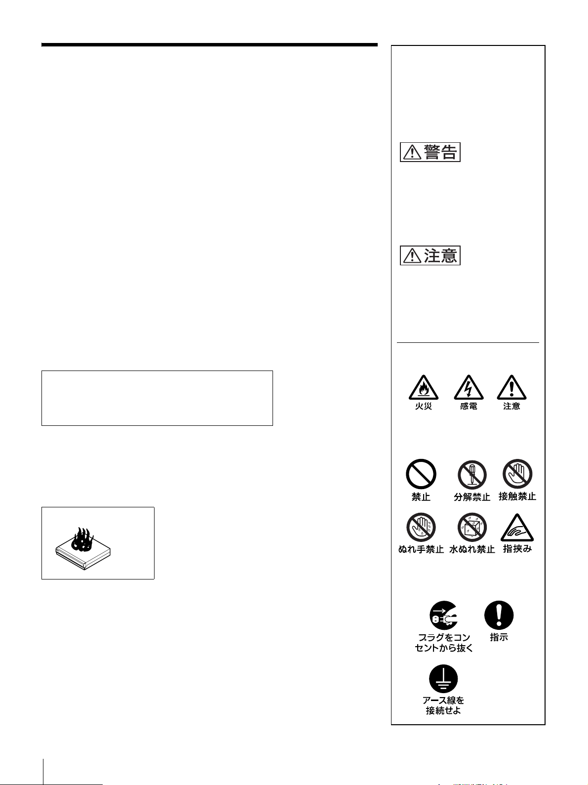
警告表示の意味
取扱説明書および製品では、次の
ような表示をしています。表示の
内容をよく理解してから本文をお
読みください。
安全のための注意事項を守る
この冊子の注意事項をよくお読みください。製品全般の注意事項が記されています。
定期点検をする
長期間、安全にお使いいただくために、定期点検をすることを、お願いします。外
観上は異常がなくても、使用頻度によって部品が劣化している可能性があり、故障
したり事故につながることもあります。詳しくは、お買い上げ店またはソニーの
サービス窓口にご相談ください。
故障したら使わない
すぐに、お買い上げ店またはソニーのサービス窓口にご連絡ください。
万一、異常が起きたら
・ 煙が出たら
・ 異常な音、においがしたら
・ 内部に水、異物が入ったら
・ 製品を落としたり、キャビネットを破損したときは
m
a 電源を切る。
b 電源コードや接続コードを抜く。
c お買い上げ店またはソニーのサービス窓口に連絡する。
この表示の注意事項を守らないと、
火災や感電などにより死亡や大け
がなど人身事故につながることが
あります。
この表示の注意事項を守らないと、
感電やその他の事故によりけがを
したり周辺の物品に損害を与えた
りすることがあります。
注意を促す記号
行為を禁止する記号
・ 炎が出たら
m
z 電源プラグをコンセントから抜くか、ブレーカーを落とす。
16
行為を指示する記号
下記の注意を守らないと、 火災や感電により死亡や大け
がにつながることがあります。
電源コードを傷つけない
電源コードを傷つけると、火災や感電の原因となることがあります。
・ 設置時に、製品と壁やラック(棚)などの間に、はさみ込んだりしない。
・ 電源コードを加工したり、傷つけたりしない。
・ 重いものをのせたり、引っ張ったりしない。
・ 熱器具に近づけたり、加熱したりしない。
・ 電源コードを抜くときは、必ずプラグを持って抜く。
・ 電源コードを接続したまま、機器を移動しない。
・ 電源コードや電源プラグが傷んだり、コンセントの差し込み口がゆるいとき
は使用しない。
万一、電源コードが傷んだら、お買い上げ店に交換をご依頼ください。
指定された電源コード、接続コードを使う
取扱説明書に記されている電源コード、接続コードを使わないと、感電や故障
の原因となることがあります。
日本国内で使用する場合
交流 100V でお使いください。
異なる電圧で使うと、火災や感電の原因となることがあります。
内部に水や異物を入れない
水や異物が入ると火災の原因となることがあります。
万一、水や異物が入ったときは、すぐに電源を切り、電源コードや接続コード
を抜いて、お買い上げ店にご相談ください。
水のある場所に設置しない
水が入ったり、ぬれたりすると、火災や感電の原因となることがあります。
雨天や降雪中、海岸や水辺での使用は特にご注意ください。
油煙、湯気、湿気、ほこりの多い場所には設置しない
上記のような場所に設置すると、感電の原因となることがあります。
取扱説明書に記されている仕様条件以外の環境での使用は、感電の原因となる
ことがあります。
JP
17
下記の注意を守らないと、火災や感電により死亡や大けが
につながることがあります。
重い製品の運搬は二人以上で
重量のある機器の開梱・運搬は、けがや事故を防ぐため、必ず二人以上で行っ
てください。
電源プラグの端子、および端子の取付け面にほこりが付着してい
る場合は、乾いた布でよく拭く
そのまま使用すると火災の原因となります。
電源プラグは、コンセントの奥まで確実に差し込む
火災、故障の原因となることがあります。
2台以上積み上げない
ラックを使用せずに2台以上積み上げると、機器が落下してけがの原因となる
ことがあります。
接続の際は電源を切る
電源コードや接続コードを接続するときは、電源を切ってください。感電や故
障の原因となることがあります。
ラックマウントレールに手や指をはさまない
ラックマウントした機器を収納するときおよび引き出すとき、ラックマウント
レールに手や指をはさみ、けがをすることがあります。
18
下記の注意を守らないと、 けがをしたり周辺の物品に損害を与えるこ
とがあります。
通風孔をふさがない
通風孔をふさぐと内部に熱がこもり、火災や故障の原因となることがありま
す。風通しをよくするために次の項目をお守リください。
・ 壁から 10 cm 以上離して設置する。
・ 密閉された狭い場所に押し込めない。
・ 毛足の長い敷物(じゅうたんや布団など)の上に設置しない。
・ 布などで包まない。
・ あお向けや横倒し、逆さまにしない。
安全アースを接続する
安全アースを接続しないと、感電の原因となることがあります。
安全アースを取り付けることができない場合は、お買い上げ店にご相談くださ
い。
接続ケーブル類を正しく配置する
電源コードや接続ケーブル類を足に引っかけると、本機が落下・転倒してけが
の原因となることがあります。充分注意して接続、配置してください。
ファンが止まったままの状態で使用しない
ファンモーターが故障すると、火災の原因となることがあります。交換は、お
買い上げ店にご依頼ください。
内部を開けない
内部には電圧の高い部分があり、キャビネットや裏ぶたを開けたり改造したり
すると、火災や感電の原因となることがあります。内部の調整や設定、点検、
修理はお買い上げ店にご依頼ください。
転倒、移動防止の処理をする
大型の製品をラックに取り付け・取り外しするときは、転倒・移動防止の処理
をしないと、倒れたり、動いたりしてけがの原因となることがあります。
安定した姿勢で注意深く作業してください。
また、ラックの設置状況、強度を充分にお確かめください。
19
下記の注意を守らないと、 けがをしたり周辺の物品に損害を与えること
があります。
安定した場所に設置する
ぐらついた台の上や傾いたところに設置すると、倒れたり落下したりして、故
障やけがの原因となることがあります。また、設置・取り付け場所の強度を充
分にお確かめください。
直射日光の当たる場所や熱器具の近くに設置・保管しない
内部の温度が上がり、火災や故障の原因となることがあります。
真夏の、窓を閉め切った自動車内では 50 ℃を越えることがありますので、ご
注意ください。
製品の上に乗らない、重い物を乗せない
倒れたり、落ちたり、壊れたりして、けがの原因となることがあります。
機器を移動する場合、あるいはお手入れの際は、電源を切って電
源プラグを抜く
電源を接続したままお手入れをすると、感電の原因となることがあります。
接続ケーブルなどもはずしてください。
長時間機器を使用しないときは、安全のため必ず電源プラグをコンセントから
抜いてください。
ぬれた手で電源プラグをさわらない
ぬれた手で電源プラグを抜き差しすると、感電の原因となることがあります。
ケーブルやコネクター部を定期的に点検する
ケーブルに傷があったりコネクターの接触が悪いと、接続不良による感電の原
因となることがあります。
1 年に 1 度は、ケーブルやコネクター部の点検をしてください。
定期的に内部の掃除を依頼する
長い間、掃除をしないと内部にホコリがたまり、火災や感電の原因となること
があります。
1 年に 1 度は、内部の掃除をお買い上げ店またはソニーのサービス窓口にご依
頼ください。(有料)
特に、湿気の多くなる梅雨の前に掃除をすると、より効果的です。
20
商標について
目次
安全のために..............................................................................16
その他安全上のご注意 ........................................................... 22
使用上のご注意 ........................................................................ 22
機能概要 ..................................................................................... 24
箱の中身を確認する ............................................................... 24
各部の名称 ................................................................................ 25
前面(カバーを開けた状態) ............................... 25
背面 .................................................................... 26
設置参考データ ........................................................................ 27
消費電流および、突入電流 ................................ 27
記録データ容量 .................................................. 27
設置する ..................................................................................... 27
ラックに設置しない場合 .................................... 28
本機をラックに設置する場合 ............................. 28
電源コードを接続する ........................................ 31
NSR-1000 シリーズと接続する ........................ 31
ほかの NSRE-S200 と接続する ........................ 31
電源を入れる / 切る ...............................................................32
電源を切る ......................................................... 32
NSR-1000 シリーズから使えるようにするには ......... 32
その他 .........................................................................................33
STATUS LED の見かた .................................... 33
故障かな?と思ったら ........................................ 34
仕様 ............................................................................................. 34
NSRE-S200 ......................................................34
・ “IPELA” および は、ソニー株式会社
の商標です。
・ その他、本書に記載されているシステム名、製品名、会
社名は一般に各開発メーカーの登録商標または商標です。
なお、本文中では、®、™ マークは明記していません。
・ 権利者の許諾を得ることなく、本機に付属のソフト
ウェアおよび取扱説明書の内容の全部または一部を
複製すること、およびソフトウェアを賃貸すること
は、著作権法上禁止されております。
・ 本機、および本機に付属のソフトウェアを使用した
ことによって生じた損害、逸失利益、および第三者
からのいかなる請求等につきましても、当社は一切
その責任を負いかねます。
・ 本機の保証条件は、同梱の当社規定の保証書の規定
をご参照ください。
・ 本機に付属のソフトウェアは、本機以外には使用で
きません。
・ ソニーが配布した本機用のソフトウェア以外のソフ
トウェアをインストールすることはできません。
・ 本機、および本機に付属のソフトウェアの仕様は、
改良のため予告なく変更することがありますが、ご
容赦ください。
録画内容の補償に関する免責事項
本機の不具合など何らかの原因で記録ができなかった場
合、不具合・修理など何らかの原因で記録内容が破損、
消滅した場合等、いかなる場合においても記録内容の補
償およびそれに付随するあらゆる損害について、当社は
一切の責任を負いかねます。また、いかなる場合におい
ても、当社にて記録内容の修復、復元、複製等はいたし
ません。あらかじめご了承ください。
目次
21
その他安全上のご注意
使用上のご注意
警告
設置の際には、容易にアクセスできる固定配線内に専用
遮断装置を設けるか、使用中に、容易に抜き差しできる、
機器に近いコンセントに電源プラグを接続してください。
万一、異常が起きた際には、専用遮断装置を切るか、電
源プラグを抜いてください。
重要
機器の名称と電気定格は、底面に記載されています。
本機をラックに設置するときは、ラックと本機の間に、
左右両側面に 4 cm 以上、後面に 10 cm 以上の空間を確
保してください。
安全上のご注意
・ 本機の電源仕様に適合する電源を使用してください。
・ 付属の電源コードを使用し、束ねたり、タコ足配線しな
いでください。定格をこえた電流が流れると、火災など
の原因となります。
・ 使用するコンセントや電源コードが正しくアースされて
いることを確認してください。
・ カバー類を外した状態で使用しないでください。カバー
類を外した状態で使用すると、火災、感電の原因となる
ことがあります。カバー類を外す必要があるときは、必
ずお買い上げ店に依頼してください。
設置上のご注意
使用・保管場所
長期間ご愛用いただくために、次のような場所での使用
および保管は避けてください。
・ 極端に暑いところや寒いところ(仕様を守ってお使いく
ださい。)
・ 直射日光が長時間あたるところや暖房器具の近く(真
夏、窓を閉め切った自動車内では 50 ℃を超えることが
ありますのでご注意ください。)
・ 湿気・ほこりの多いところ
・ 激しい振動があるところ
・ 強い磁気の発生するものの近く
・ 強力な磁気を発生するテレビ、ラジオの送信所の近く
通風孔をふさがない
・ 本機内の温度の上昇を防ぐため、本機の側面にある通風
孔をふさがないでください。本機の両側面、後面、上面
は、壁や天井から 10 cm 以上離してください。
・ 本機を密閉された箱に入れて使用しないでください。
・ 本機背面のファンの通風孔付近に、ケーブルやその他の
障害物がこないように設置してください。通風孔をふさ
ぐと内部に熱がこもり、火災や故障の原因となることが
あります。
・ 本機をラックに設置して使用するときも、本機背面の
ファン、前面の通気孔付近に、ケーブルやその他の障害
物がこないように設置してください。また、動作環境が
上記の条件を満たす場所に設置してください。
その他安全上のご注意 / 使用上のご注意
22

水平位置で使用してください
・ 本機は水平平面上で動作するように設計されています。
・ 傾いた場所に設置しないでください。強い衝撃を与えな
いでください。
・ 落としたりして強い衝撃を与えると故障することがあり
ます。
・ 本機をラックに設置するときは、水平が保てるように取
り付けてください。高さを合わせないで取り付けると、
誤動作の原因となります。また、本機をラックに取り付
けたときに、ラックの重量バランスが崩れて転倒するこ
とを防ぐため、ラックに転倒防止金具などを取り付ける
ことをおすすめします。
お手入れについて
・ お手入れをする前に、電源プラグをコンセントから抜い
てください。
・ キャビネットやパネルの汚れは、乾いた柔らかい布で軽
くふき取ってください。汚れがひどいときは、中性洗剤
溶液を少し含ませた布で汚れをふき取り、乾いた布で仕
上げてください。
・ アルコール、シンナー、ベンジンや殺虫剤など、揮発性
のものをかけると、変質したり塗料がはげることがあり
ます。
・ 本機前面の通風孔にほこりがたまることがあります。そ
の場合は、衝撃・振動を与えないように注意して除去し
てください。
輸送のときは
付属のカートン、または同等品で梱包し、急激な衝撃を
与えないようにご注意ください。
HDD 内蔵機器に対する注意事項
本機には、ハードディスクドライブ(以下 HDD と称す
る)が搭載されています。HDD は精密部品であり、衝
撃・振動・静電気・温度・湿度が原因で故障したり、
HDD 内のデータが破損する恐れがあります。本機を設
置・使用するときは、以下の注意事項をよくお読みのう
え、慎重に取り扱ってください。
・ ラック内にあるすべての HDD 搭載機器に衝撃を与えな
いでください。
・ 本機をラックから出し入れするとき、ラック内に通電中
の HDD 搭載機器がある場合は、必ずその機器の電源を
オフにしてください。
・ 本機の外装を取り外さないでください。
・ 本機を床などに置くときは、本機の底に必ず指定のゴム
脚がついている状態で、静かに降ろしてください。脚が
付いていない場合は、脚を取り付けてから置いてくださ
い。
・ 振動を発生する機器の近くには置かないでください。
電源オフ後 30 秒間は作業しない
電源をオフにした後もしばらくの間は、HDD 内のディス
クは慣性で回転しており、ヘッドは不安定な状態にあり
ます。この期間は、通電中以上に衝撃・振動に弱い状態
です。電源オフ後、最低 30 秒間は軽い衝撃も与えないよ
うにご注意ください。30 秒以上経過すれば、(ディスク
が静止するので)作業を開始できます。
温度・湿度に関するご注意
適正範囲内の温度・湿度のある場所で、保管・使用して
ください。(仕様を守ってお使いください。)
HDD に不良症状が現れた場合
万一、本機の HDD が故障した(不良症状が現れた)と思
われる場合でも、本機の取り扱いは、上記と同様に行っ
てください。不良内容の確認や不良解析を行うまでの損
傷の拡大を防ぎます。
HDD を含む有寿命部品の交換
HDD、ファン、バッテリーは有寿命部品として定期的な
交換が必要です。常温でのご使用の場合、2 ~ 3 年を目
安に交換してください。ただし、交換時間は目安であり、
部品の寿命を保証するものではありません。交換の際は
お買い上げ店にご相談ください。
衝撃・振動を与えない
衝撃・振動が加わると HDD が故障あるいは HDD 内の
データが破損される恐れがあります。
・ 本機を輸送する場合は、指定の梱包材料で梱包してくだ
さい。台車などで搬送する場合は、振動の少ない台車を
使用してください。過度な衝撃・振動が加わると HDD
が故障するおそれがあります。
・ 通電中は本機を移動しないでください。本機をラックか
ら出し入れするときも、必ず電源をオフにした状態で
行ってください。
使用上のご注意
23
機能概要
箱の中身を確認する
NSRE-S200 は、ソニーのネットワークサーベイランス
サーバー NSR-1200/1100/1050H(以降、NSR-1000
シリーズと呼びます)専用の拡張ストレージユニットで
す。NSR-1000 シリーズに本機を 7 台まで接続できま
す。
大容量ハードディスクに長時間記録
大容量ハードディスクを内蔵していますので、高画質で
も長時間記録可能です。参考例として、「設置参考デー
タ」 (27 ページ)をごらんください。
省スペースの 2U、19 インチラックマウントタイプ
オプション(別売り)のラックマウントキットを使うと、
EIA STANDARD(ユニバーサルピッチ)の 19 インチ
ラックに設置できます。
高信頼性の実現
NSRE-S200 は RAID 51)に対応し、高信頼性を実現してい
ます。仮にハードディスクのうち 1 台が故障した場合でも、
システムの運用が継続できます。
1) RAID 5 とは、データだけでなくパリティと呼ばれる誤り訂
正符号も複数のハードディスクに分散して記録するシステム
です。これにより 1 台のハードディスクが故障しても、運用
を継続可能とする仕組みですが、データ復旧を保証するシス
テムではありません。また、故障したハードディスクを交換
後の再構築中は、内部処理の負荷が高くなりますので、設定
している記録レートで画像を記録できなくなる場合がありま
す。
パッケージを開けたら、以下のものが揃っているかお確
かめください。付属品の中に欠けているものがあるとき
は、お買い上げ店にご連絡ください。
・ NSRE-S200 拡張ストレージユニット本体(1)
・ ミニ SAS ケーブル(1 m)(1)
・ 電源コード(1)
・ フロントパネルキー(2)
・ 設置説明書(本書)(1)
・ 安全のために(1)
・ WEEE(冊子)
・ 保証書(冊子)(1)
・ 保証シート(1)
・ ゴム足(4)
メモ
・ 上記以外に、説明書や書類などが同梱されている場合が
あります。
・ 箱と梱包材は、本機を移動したり輸送したりするときに
必要です。捨てないで必ず保管してください。
・ ラックマウントキット(NSR-RM1)はオプション(別
売り)です。
重要
本書では、本機の設置、NSR-1000 シリーズとの接続に
ついて説明いたします。本機を使用するために必要な設
定などについては、NSR-1000 シリーズの『設置説明書』
および『ユーザーガイド』をご覧ください。
機能概要 / 箱の中身を確認する
24
各部の名称
678
前面(カバーを開けた状態)
12345
POWER NETWORK 1 2 3 4HDD 1 2 3 4 ERRORSTATUS
A POWER LED
電源が入ると、緑色に点灯します。
スタンバイモードのときはアンバー色に点灯します。
B NETWORK LED
背面の LAN コネクターにそれぞれアクティビティが
あるときに緑色に点灯します。
C HDD LED
内蔵ハードディスクのアクセス時に緑色に点滅しま
す。 ハードディスクにエラーが発生したときはアン
バー色に点灯します。
D STATUS LED(1 ~ 4)
本機の起動時に、1→ 2 → 3 → 4 の順で点灯します。
また、エラーが発生したときには、ERROR LED が
点灯/点滅するとともに STATUS LED が点灯し、
エラーの内容を表示します。
詳細は、「STATUS LED の見かた」 (33 ページ)を
参照してください。
E ERROR LED
エラーが発生した場合に点灯/点滅します。
F 電源スイッチ
押すと、電源が入ります(電源を切ることはできませ
ん)。
G 鍵穴
付属の HDD トレイ施錠鍵を使って、フロントベゼ
ルをロックします。ロック時には、フロントベゼル
は引き出せません。また、フロントベゼルを引き出
した状態でロックしないでください。
ロック時とロック解除時の鍵穴の位置は、以下のと
おりです。
ロック時 ロック解除時
H 通風孔
本体前面から背面へのエアフローの入り口です。
通風孔をふさいだり、通風孔の内側のメッシュにほ
こりがたまったりして、エアフローが妨げられない
ようにしてください。エアフローが妨げられると内
部に熱がこもり、火災や故障の原因となることがあ
ります。
各部の名称
25
背面
65
7
231
A ファン
ファンの通風孔をふさがないように注意してくださ
い。通風孔をふさぐと内部に熱がこもり、火災や故
障の原因となることがあります。
B 電源スイッチ
1 の方に押すと、電源が入ります。
C RS-232C 端子
メンテナンス用です。
D ミニ SAS 出力端子× 2
下流の NSRE-S200 に接続するためのミニ SAS
ケーブルを接続します。
上下の端子に違いはありません。
4
F LAN 端子
メンテナンス用です。
ご注意
安全のために、周辺機器を接続する際は、過大電圧
を持つ可能性があるコネクターをこの端子に接続し
ないでください。
G 電源端子
付属の電源コードを接続します。
E ミニ SAS 入力端子
上流の NSR-1000 シリーズや NSRE-S200 に接続
するためのミニ SAS ケーブルを接続します
26
各部の名称
設置参考データ
消費電流および、突入電流
機種 電源 消費電流 突入電流
NSRE-S200
記録データ容量
100 V 0.8 A
220 V 0.4 A
設置する
設置場所のスペースや強度を充分確認してから、本機を
設置します。
本機の質量は約 12 kg で、大きさは以下のとおりです。
13 A
87 mm
NSRE-S200 の記録データ容量は以下になります。
機種 記録データ容量
NSRE-S200 1,396 GB
注)データ容量に関しては、1 GB を 1,024 × 1,024 ×
1,024 =約 10 億 7,374 万バイトとして計算してい
ます。
430 mm
上から見たところ
430 mm
フロントベゼルを閉じたとき
417 mm
417 mm
417 mm
40 mm
377 mm
設置参考データ / 設置する
27
フロントベゼルを開けたとき
117 mm
106 mm
102 mm
123 mm
494 mm
479 mm
377 mm
377 mm
本機をラックに設置する場合
オプション(別売り)のラックマウントキットを使用し
て、本機をラックマウントに設置します。
ご注意
・ 本機のオプション(別売り)以外のラックマウントキッ
トを使用すると、火災や感電、けがなどの原因となりま
す。危険ですのでおやめください。
・ 本機をラックに設置した場合、本機の上に重い物を載せ
ないでください。
・ あらかじめ本機を取り付ける位置を決め、ラックにフェ
ルトペンなどで印を付けておくことをおすすめします。
ラックの高さを合わせないで本機を取り付けると、誤動
作の原因となりますのでご注意ください。
・ ラックマウントキットのお求めは、お買い上げ店にご連
絡ください。
別売のラックマウントキットを使用すると、本機をラッ
クに据え付けることができます。
ラックに設置しない場合
付属のゴム足を本機に取り付ける。
底面が見えるようにして、立てて置き、ゴム足の接着面
を底面の四隅に貼り付けます。
図の位置を参考にして貼ってください。
シールをはがす
ゴム足
インナーレールを取り出す
レールアセンブリーからインナーレールを取り出します。
1
レールアセンブリーからインナーレールを、止まる
位置まで引き出す。
レールアセンブリーの裏側
インナーレール
レールアセンブリー
2
レールアセンブリーを裏返し、緑色のタブを矢印の
方向に引いてロックを解除しながら、インナーレー
ルを引き抜く。
28
設置する
本体底面
緑色のタブ
3
同様にして、もう 1 本のレールアセンブリーからイン
ナーレールを引き抜く。
メモ
インナーレールは本機に、レールアセンブリーは
ラックに取り付けます。
本機の準備をする
ラック取り付け金具とインナーレールを取り付けます。
1
付属の皿ネジを使って、本機側面の前側にラック取
り付け金具を取り付ける。
ラック取り付け
金具
皿ネジ
ラックの準備をする
ラックにレールを取り付けます。
1
レールを取り付ける位置を決める。
レールを取り付ける位置に、フェルトペンなどで印
を付けておくことをおすすめします。
ご注意
レールの高さを合わせないで本機を取り付けると、
誤動作の原因となりますのでご注意ください。
2
ラックにレールを取り付ける。
1 お使いのラックに合わせて、レールの長さを調
節する。
2
付属のナベネジを使って、インナーレールを取り付
ける。
緑色のタブ
緑色のタブ
ご注意
付属以外のネジを使用すると、故障の原因となりま
す。レールの取り付けには、必ず付属のネジを使用
してください。
ナベネジ
2 付属のトラスネジとワッシャーを使って、前側
と後ろ側のフレームにレールを固定する。
レール
トラス
ネジ
ワッシャー
設置する
29
本機をラックに取り付ける
本機をラックに入れて固定します。
ご注意
けがや事故を防ぐため、必ず二人以上で行ってください。
1
レールアセンブリーからスライドレールを引き出す。
2
本機を持ち上げ、インナーレールをスライドレール
の溝(白い部分)に載せて、止まるところまでスラ
イドさせる。
3
緑色のタブを手前に引いてロックを解除しながら、
本機をラックの奥までスライドさせる。
緑色のタブ
インナーレール
4
付属のナべネジを使って、本機を固定する。
ナベネジ
30
設置する
 Loading...