

Sony Ipela NSR-1000 Series First Step Manual

Network
Surveillance
4-130-100-25 (1)
Server
First Step Guide
Software Version 1.5 and Later
NSR-1000 Series
© 2008 Sony Corporation
Introduction
This First Step Guide assumes the following conditions and usage for your system, and explains the procedures up until
actual operation. Use this document as a guide for setting up the unit before actual operation.
Conditions and usage assumed in this guide
• System includes only Sony network cameras and analog cameras.
• Pan, tilt, and zoom operations for analog cameras are not used.
• Audio is not used.
• Only scheduled recording is performed.
• Internal hard disk is not partitioned (partition settings not configured).1)
1) Be aware that if you decide to partition the internal hard disk later on, data that has already been recorded will be lost.
For more advanced operations…
If your operating environment or purpose of use requires the more advanced functions and settings available on the
NSR, refer to the Installation Manual (separate document) or User’s Guide (PDF) for details.
Examples of advanced operations
• Using non-Sony network cameras.
• Recording to storage expansions.
• Partitioning the internal hard disk or external storage, and assigning different storage locations based on the camera
or type of recording.
• Alarm recording.
• Controlling pan, tilt, and zoom on analog cameras.
• Using audio.
• Using client software (RealShot Manager Advanced).
• Customizing the layout.
• Advanced searching.
• Consolidating user management operations for multiple servers.
• Exporting video or still images to external media.
• Automatically presetting the camera in response to external alarms, and adjusting options such as the layout.
2
Introduction
Installation and Setup Procedure
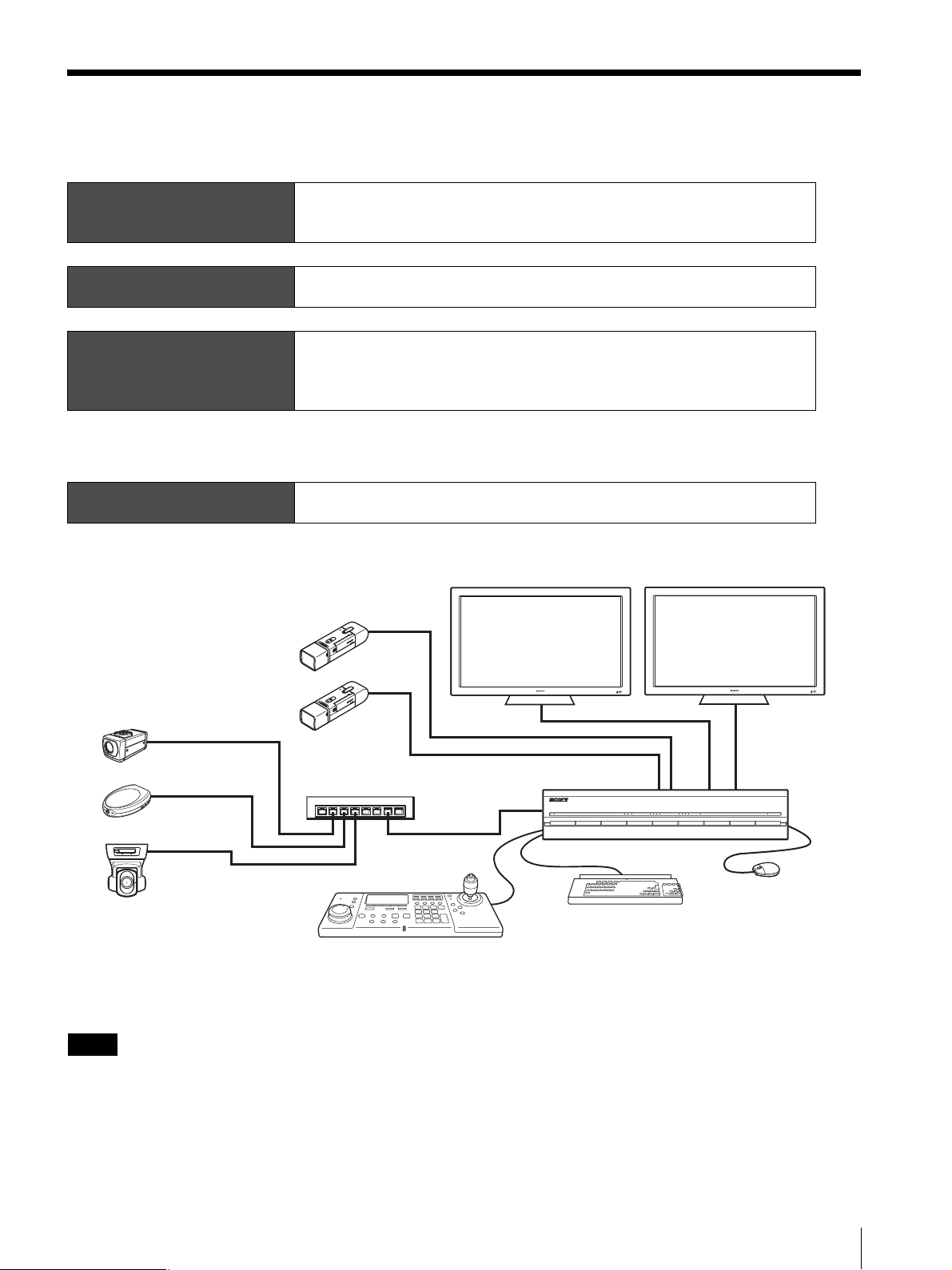
This document provides general explanations on installation and setup of systems that are constructed as follows.
Step 1
Installation
↓
Step 2
System Setup
↓
Step 3
Software Setup
↓
Settings complete
↓
Step 4
Verification
• Install the NSR
• Prepare devices
• Connect devices
• Turn on the unit
• Configure initial settings with Setup Wizard
• Log on to NSR
• Perform basic configuration
• Register cameras automatically
• Configure scheduled recording automatically
• Verify monitoring
• Verify image recording and playback
Monitors
Analog cameras1)
Network cameras
Network switch
POWER 1 2 3NETWORK 1 2 3 4HDD 1 2 3 4 ERRORSTATUS REC
Mouse
Keyboard
System Controller
1)The NSR-1050H is standard equipped with an NSBK-A16 analog encoder board, but the NSR-1200/1100 requires an optional NSBK-A16 or NSBK-
A16H expansion.
To use the NSBK-A16H, the software on the NSR must be updated to version 1.4 or later.
Notes
• Be sure to read the Safety Regulations (separate document) before installing the unit.
• For details on optional NSBK-A16/A16H expansions, contact your Sony dealer.
• PDF manuals are included with this unit. For details on how to use the PDF manuals, refer to the Installation Manual
(separate document).
Installation and Setup Procedure
3
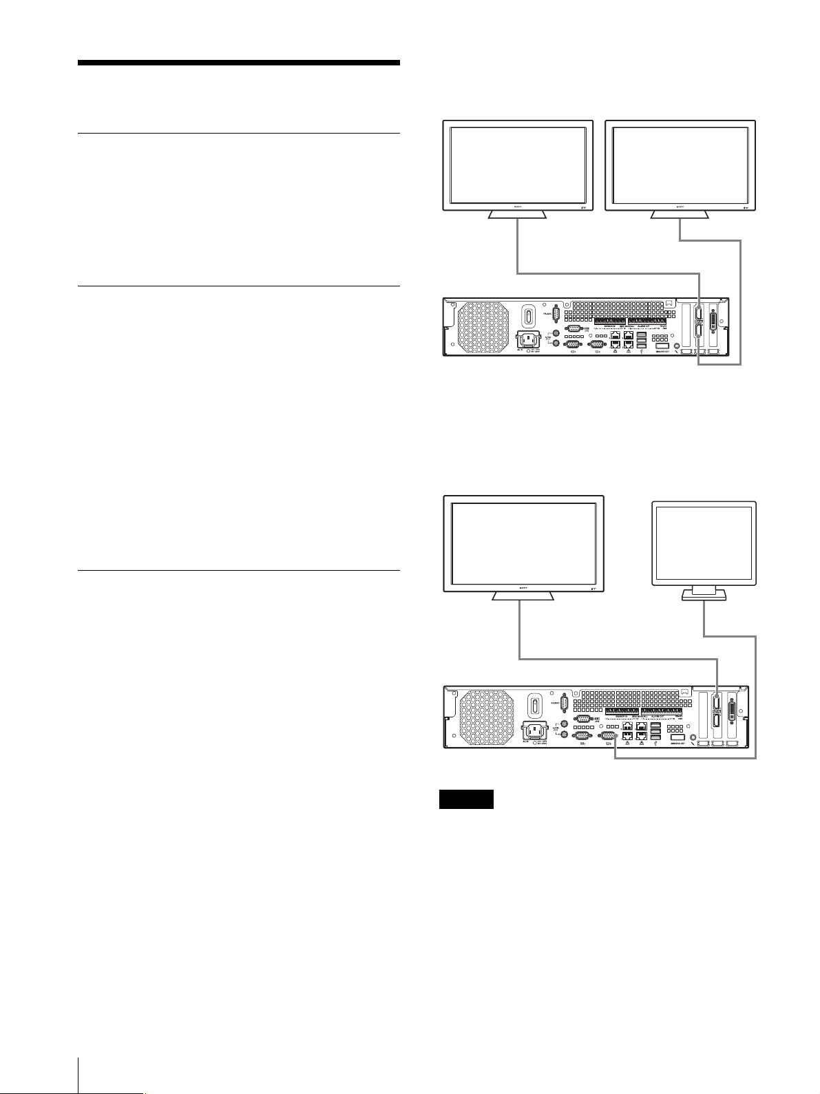
Example) When connecting two HDMI monitors
Step 1: Installation
Installing the Unit
Before setting up, be sure that the location for
installation provides sufficient space and strength to
support the unit.
For details on installation, refer to the Installation
Manual (separate document).
Preparing Devices
Prepare the following devices based on your intended
use.
• Monitors ×2 (operations/settings; hot spot
monitoring)
• Monitor cable (if necessary)
•Keyboard
•Mouse
• System Controller
• Network cameras
•Network switch
•LAN cable
• Analog cameras (when using an NSR-1050H unit or
an NSBK-A16/A16H expansion)
Monitor 1
(operations/settings)
HDMI monitor connector 1
HDMI monitor connector 2
Monitor 2
(hot spot monitoring)
Example) When connecting an HDMI monitor
and VGA monitor (HDMI monitor used for
operations)
Monitor 1
(operations/settings)
Monitor 2
(hot spot monitoring)
Installing Devices
Connecting the Monitors
Connect the monitor for operations and settings to
monitor connector 1, and connect the monitor for hot
spot monitoring to monitor connector 2.
For systems with only one monitor, be sure to connect
the monitor to monitor connector 1.
HDMI monitor connector 1
RGB monitor connector 2
Caution
• There are restrictions on the combination of monitor
connectors that you can use. Be sure to read
“Connecting a Monitor” and “Monitor Connection
Examples” in the Installation Manual (separate
document) before connecting the monitors.
• When monitors are connected via a monitor switch,
images may not always display. We recommend
connecting monitors directly to the unit.
Step 1: Installation
4
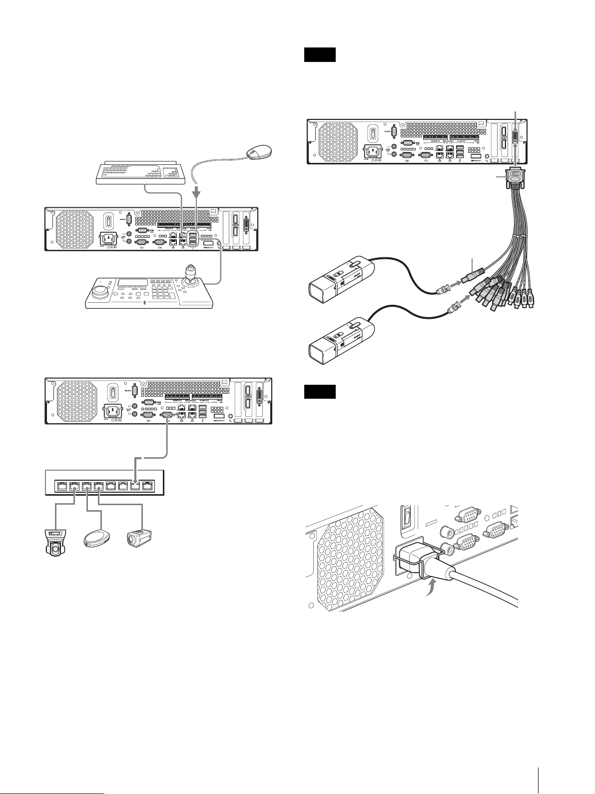
Connecting the Keyboard, Mouse and
System Controller
Connect the devices to the USB connectors on the front
and rear of the unit.
Example) When connecting to the USB
connector on the rear
Mouse
Keyboard
Note
We recommend connecting the cameras in an order that
will make it easy to operate them on the screen.
Analog camera cable input connector
Analog camera input cable
System Controller
Connecting the Network Cameras
Connect the network cameras and the unit to the same
network segment.
LAN connector 1
Network switch
Analog camera 1
Analog camera 2
Note
Video input connecter
(black)
The white connectors (A1 to A4, 4 total) on the analog
camera input cable are used for audio input.
Connecting the Power Cord
Connect the power cord to the power supply connector.
Attach the safety clip to prevent the power cord from
disconnecting.
Network camera 3
Network camera 2
Network camera 1
Connecting the Analog Cameras (only
with the NSR-1050H or NSBK-A16/A16H
expansion)
Use the supplied analog camera input cable to connect
the analog cameras.
Connect the analog cameras to the black video input
connectors. Each of the connectors on the analog camera
input cable is labeled with a BNC number from V1 to
V16. The connected cameras are assigned as “Analog
camera 1,” “Analog camera 2,” and so on, based on the
order of the BNC numbers to which they are connected.
Step 1: Installation
5
 Loading...