

Page 1

Network
Surveillance
Recorder
3-869-888-16 (1)
User’s Guide
Before operating the unit, please read this manual
thoroughly and retain it for future reference.
NSR Series
© 2006 Sony Corporation. All rights reserved.
Page 2

Contents
Introduction
Overview.......................................................................5
Features and Functions ..............................................8
System Requirements...............................................14
Initial Configuring the System
Overview.....................................................................15
Configuration Flow....................................................15
System Configuration
Modifying the System Configuration.......................25
Reconstructing Data Volume (Changing RAID Types)
Front ................................................................................ 8
Rear ............................................................................... 11
(First Time: Basic Initial Setup).........................16
Basic Configuration ......................................................16
Camera IP Address Configuration and Registration
to NSR .................................................................22
(Only the NSR-100/50) ........................................36
Basic Operation
Monitoring Live Images
Overview.....................................................................39
Logging On to the NSR .............................................40
Basic Window Operations ........................................42
Changing the Password............................................44
Logging Off From the NSR .......................................45
Locking the NSR........................................................46
Shutting Down and Restarting the NSR ..................47
Saving and Restoring Configuration Data ..............47
Saving Configuration Data............................................ 47
Restoring Configuration Data ....................................... 48
Exporting Log Files ...................................................50
Starting Up the Setup Menu .....................................51
Overview.....................................................................53
Monitoring Window Functions and Operation........53
Monitoring Window (Monitor 1).................................. 54
Monitoring Window (Monitor 2).................................. 57
Monitor Window........................................................... 57
Selecting the Live Images.........................................59
Selecting the Live Images ............................................. 59
Controlling Cameras ..................................................... 60
2
Page 3

Monitoring in Sequence Mode .................................62
Displaying Camera Images in the Hot Spot Monitor
Window ................................................................63
Displaying Images in the Hot Spot Monitor Window
When There is Sensor Input or an Alarm ........... 63
Monitoring Audio From Cameras.............................63
Muting Sound From Cameras....................................... 63
Recording Live Images .............................................64
Starting Recording ........................................................64
Stopping Recording....................................................... 64
Selecting a Camera From Recording Status and
Stopping Recording ............................................. 65
Playing Back Recorded Images ...............................65
Selecting a Monitor Window and Starting Playback .... 65
Quick Search ................................................................. 67
Selecting From Recording List ..................................... 67
Searching for Recorded Images to Play Back............... 68
Exporting....................................................................71
Exporting Movies.......................................................... 71
Exporting Still Images ..................................................75
Option Window (Auxiliary Function Area) ..............77
Alarm Log ..................................................................... 77
System Log ...................................................................79
Alarm Output ................................................................80
Sensor Input ..................................................................81
VMD (Recorder) ........................................................... 81
Manual Trigger ............................................................. 82
Settings
Overview.....................................................................83
Configuration Window Basic Operation..................83
Advanced Configuration...........................................84
General .......................................................................... 84
Camera .......................................................................93
Setting IP Addresses after Detecting Cameras
Automatically (Camera IP Setup)........................ 93
Detecting Cameras on the Network Automatically and
Registering Multiple Cameras............................. 97
Specifying the IP Address or Host Name of a Camera. 99
Deleting a Camera....................................................... 101
Configuring the Advanced Settings of Cameras......... 101
Sensor Input.............................................................121
Adding a Sensor Input Pin to the NSR .......................121
Deleting a Sensor Input Pin Created on the NSR .......122
Modifying Sensor Input Pin Settings on the NSR and
the Camera......................................................... 123
Setting a Video Motion Detection (Camera) Pin ........ 124
Alarm Output............................................................130
Modifying Alarm Output Pin Settings........................ 130
3
Page 4

Miscellaneous
Controlling Alarm Outputs Manually......................... 131
Action .......................................................................131
Recording Schedule................................................135
Creating a New Recording Schedule .......................... 136
Modifying Schedule Settings...................................... 142
Monitor .....................................................................145
Adding a Monitoring Sequence ..................................149
User...........................................................................151
Creating a User............................................................ 151
Functions Supported by the Remote Control
Keys ...................................................................154
User Permissions ....................................................157
System Setup Menu Items......................................159
Monitoring Setting Items ........................................160
STATUS LED ............................................................168
I/O Port......................................................................170
Pin Assignment of I/O Port......................................... 170
Using the I/O Receptacle ............................................171
Wiring Diagram 1 for Sensor Input ............................171
Wiring Diagram 2 for Sensor Input ............................171
Wiring Diagram for Alarm Output .............................172
Notes and Limitations .............................................173
Camera Resolution Details.......................................... 173
Camera Frame Rate Details ........................................175
Important Precautions (Read Carefully) .....................175
Notes ...........................................................................176
Troubleshooting ......................................................181
Specifications ..........................................................184
Program ©2006 Wistron Corporation
Documentation ©2006 Sony Corporation
©2006 Sony Corporation
Trademarks
• “IPELA” and are trademarks of Sony Corporation.
• Microsoft and Windows are either registered trademarks or trademarks of Microsoft Corporation in the United States and/or other countries.
• Linux is either a registered trademark or trademark of Linus Torvalds in the United States and/or other countries.
• Red Hat is a registered trademark or trademark of Red Hat, Inc. in the United States and/or other countries.
• NFS is trademark of Sun Microsystems, Inc. in the United States and/or other countries.
• Adobe, Acrobat, and Acrobat Reader are either registered trademarks or trademarks of Adobe Systems Incorporated in the United States and/or other countries.
• Ethernet is a registered trademark of Fuji Xerox Co., Ltd.
• Other products or system names appearing in this document are trademarks or registered trademarks of their respective owners.
Further, the ® or ™ symbols are not used in the text.
4
Page 5
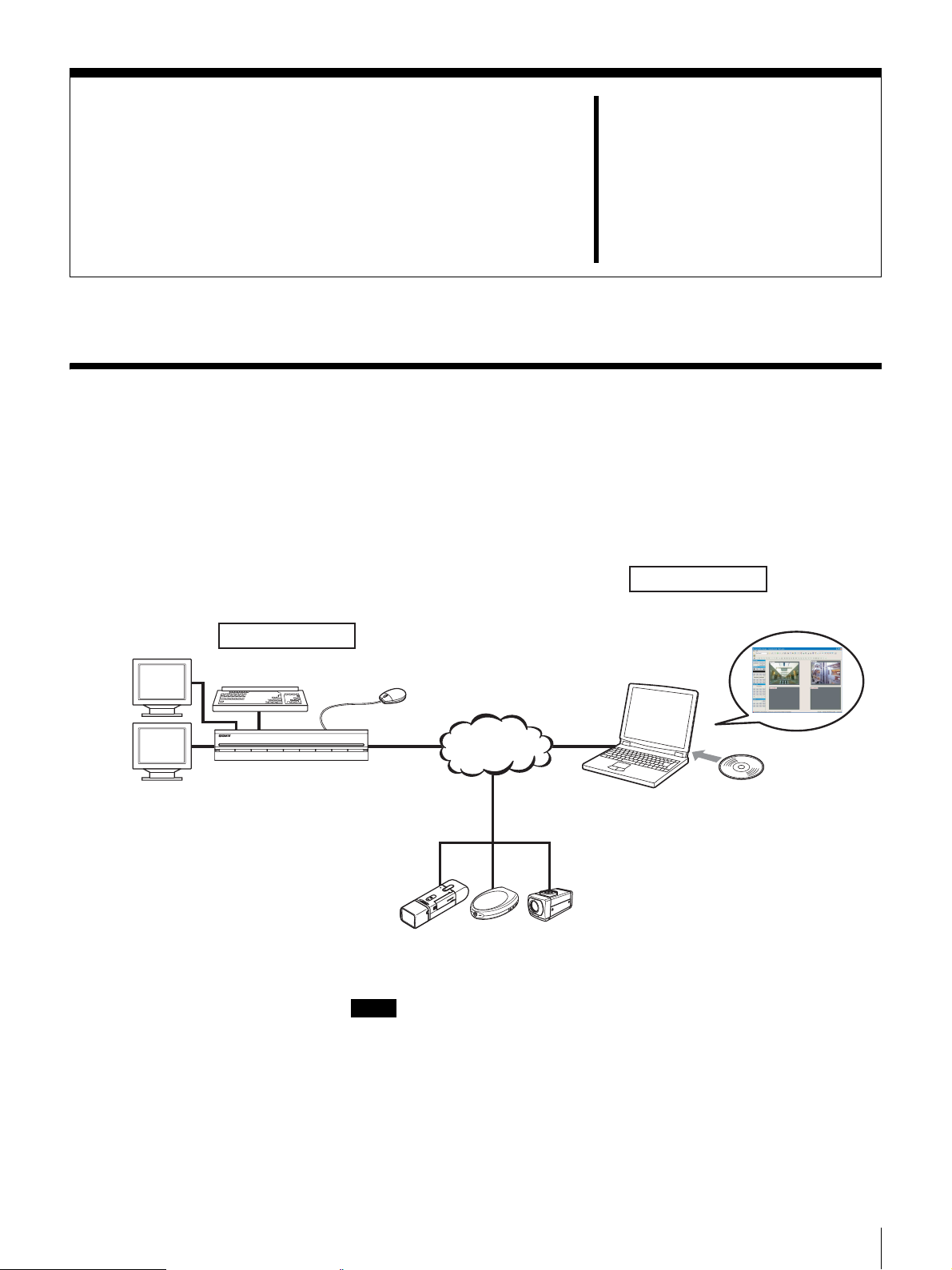
Overview
Introduction
The NSR series is a dedicated surveillance recorder equipped with preinstalled
surveillance software that runs on their dedicated operating system. The NSR
allows you to monitor and record network camera images (JPEG or MPEG4). It
also allows you to play back the recorded images and search through them,
making the NSR a truly versatile monitoring tool.
Chapter
Surveillance room
1
Monitor
Machine room
Keyboard
NSR
RealShot Manager Controller
is used for surveillance and
configuration.
Mouse
Network
Windows PC
Surveillance cameras
Notes
• When using RealShot Manager as a remote controller for the NSR, select
[Controller] during installation of RealShot Manager.
• With two monitors connected to the NSR, you can perform settings and
monitoring operations on monitor 1 and hot spot monitoring on monitor 2.
Installing
RealShot Manager
Controller Software
Chapter 1 Introduction
5
Page 6

Control compatible cameras from remote locations
You can pan, tilt, and perform zoom operations of compatible cameras from the
NSR network. The NSR provides control of focus and bright level, and also
supports audio recording from network cameras.
* Microphones and speakers sold separately.
Compatible with analog cameras
You can monitor and record images from analog cameras when you purchase
and install an optional camera server (SNT-V704).
The network ports supporting for gigabit (1000 Base-T)
As the NSR-100/50 is equipped with three network ports, you can configure the
system so that the camera network is kept separate, preventing the camera
network data from being affected by the other network data. There is more than
enough space to receive data from multiple cameras because the three ports
support gigabit transfer rates.
The NSR-25 is equipped with one network port supporting gigabit transfer rates.
Large-capacity hard disks allow recording for long periods of time
The NSR is equipped with large-capacity hard disks. The NSR-100 can record up
to approximately 920 GB
460 GB
1)
of data, and the NSR-25 can record up to approximately 230GB1) of
data. For example, if you record images from 16 cameras at 1 fps
one frame equals about 31 KB) with the NSR-100, you can record approximately
a month’s worth of images (15 hours a day)
1) Includes the database capacity managed by the internal software.
2) fps: frames per second.
3) When set to RAID 0.
1)
of data, the NSR-50 can record up to approximately
2)
(VGA, JPEG;
3)
.
Slim type (2U), space-saving 19-inch rack mounting model
With the optional rack mounting kit (sold separately), the recorder can be
installed in a standard universal pitch EIA 19-inch rack.
High-resolution up to 480 fps (VGA, JPEG) recording
The NSR-100 can support up to 64 cameras, the NSR-50 can support up to 32
cameras, and the NSR-25 can support up to 20 cameras
images at a total frame rate of 480 fps
2)
(240 fps with the NSR-50, 120 fps with
1)
. The NSR-100 records
the NSR-25), VGA (640 × 480 pixels) resolution, JPEG (1 frame approx.
31 KB) image format, for a crisp image quality.
1) For cameras that support image sizes of 1,280 × 960 pixels or more, the NSR-100 can
support up to 8 cameras, and the NSR-50/NSR-25 can support up to 4 cameras.
2) Maximum frame rate when 16 cameras are connected to the recorder. Each camera
has a frame rate of approximately 30 fps. This frame rate may become less because
of fragmentation on the internal hard disks. Values are based on Sony measurements.
These values are not guaranteed, as performance may change due to the user’s
operating environment.
High reliability
The NSR-100/50 offers high reliability through:
• NSR-100: RAID 0, 1+0, and 5
• NSR-50: spanning
1)
and RAID 1
When used with a RAID 1, 1+0 or 5, the system can continue functioning even
if one of the hard disks develops a malfunction. Similarly, because the system
software and settings are stored on the internal flash memory of the NSR, if the
system software develops a malfunction, lightning-quick restoration of the
system is possible. The NSR also supports uninterruptible power supplies
2)
(UPS)
1) Spanning: Function allowing several hard disks to be virtually seen as one.
2) Sony recommendation only.
, making them extremely reliable systems.
Chapter 1 Introduction
6
Page 7

Notes
• When you use RAID 0 with the NSR-100, spanning with the NSR-50, or the
NSR-25 there is no data redundancy. Also, storage capacity varies according
with the RAID level.
• RAID is not available for the NSR-25.
Easy monitoring operation by remote control
In addition to using your keyboard and mouse to operate the NSR, but you can
also use the joystick and buttons of the optional RM-NS10 remote control unit.
Furthermore, the screen layout is based on equally split screen segments, and
can be used seamlessly with a conventional recorder.
Note
You will need to use your keyboard and mouse to make initial NSR settings.
Other features
• You can monitor, record, play back, and operate images from cameras that
support 1,280 × 960 pixel size.
• You can display the images from up to 64 cameras (8 × 8 images) on one
screen.
• The NSR is capable of manual, scheduled, and alarm recording, among others.
• The NSR is equipped with a motion detection function
1)
(Video Motion
Detection (Recorder)).
• Run searches for recorded images by camera name, date, alarm, and other
methods.
• Create privacy zones by using the dynamic masking functions
2)
. Dynamic
masking covers pan, tilt, and zoom.
• Precise alarm processing is made possible by performing the various types of
filtering
3)
that use the image processing results sent from the camera in the
form of object information metadata. Because filtering can be applied to
metadata that has already been recorded, you can also search for areas of
interest after recording is finished.
• With an internal drive, the NSR-100/50 is capable of writing data to DVD-R,
DVD+R, or CD-R/RW media.
The NSR-25 is capable of writing data to CD-R/RW media.
• Audio recording and playback
1) Some functions are limited depending on the number of cameras connected.
2) Some functions are limited depending on which camera models are connected.
3) To perform motion detection and object detection using metadata, a camera that
supports motion detection by metadata is required. The use of metadata is supported
for up to 32 cameras.
4) The optional active speakers are required.
4)
are also supported for compatible cameras.
Chapter 1 Introduction
7
Page 8
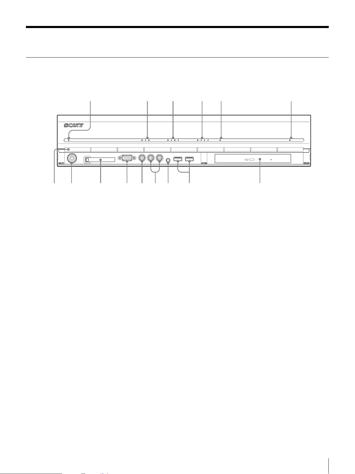
Features and Functions
708q
9q
q
q
q
Front
NSR-100/50
123 4 5 6
POWER 1 2 3NETWORK 1 2 3 4HDD 1 2 3 4 ERRORSTATUS REC
a
f
g
d
s
A Power LED
Alternates between green and amber lights when the unit is starting up.
Lights green when startup is complete.
Lights amber when it is on standby.
B Network LED (1 to 3)
Lights green when there is activity at the corresponding LAN connector at the
rear of the NSR.
C HDD LED
Blinks green when the internal hard disks are accessed.
Lights amber when an error occurs with a hard disk.
D Status LED (1 to 4)
Lights in sequence (1, 2, 3, 4) when the NSR starts.
When an error occurs, the corresponding status LED lights together with the
error LED, which lights or blinks to indicate the type of error.
For details, see “STATUS LED” (page 168).
E Error LED
Lights or blinks when an error occurs.
F REC LED
Lights when recording images.
G DVD/CD drive
Use this drive to write data from the NSR hard disks to DVD and CD.
* For details on compatible media, refer to “Notes and Limitations” (page 173).
H USB connector
Use this connector to connect a USB keyboard, mouse, USB flash memory or
the RM-NS10 remote control unit to the NSR.
Chapter 1 Introduction
8
Page 9
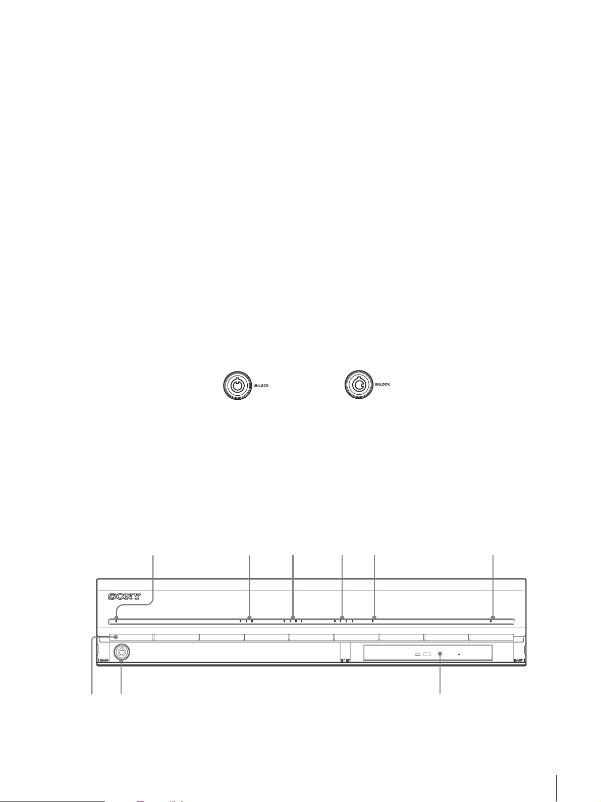
I Audio input connector*
789
Use this connector to input audio from a peripheral audio device, such as a
microphone.
J Audio output connectors (L and R)
Use these connectors to output audio to a peripheral audio device.
K Video output connector
Use this connector to output video to a peripheral video device, such as a VCR.
The displayed images are the same as those for monitor connector 1.
L Monitor connector 1
Use this connector to connect a monitor.
M CompactFlash card slot
Use this slot to save configuration data from the NSR hard disks to a
CompactFlash card.
N Lock
Use this in conjunction with the supplied front panel key to lock the front bezel.
When the front bezel is locked, you cannot pull out the front bezel. Also, do not
lock the front bezel when the front bezel is pulled out. You can distinguish the
locked position from the unlocked position by looking at the lock, as illustrated
below.
NSR-25
The front bezel is
locked
The front bezel is
unlocked
O Vent holes
These openings allow air to flow from the front of the NSR to the rear.
Do not block the vent holes, allow dust to accumulate in the inner mesh of the
vent holes, or obstruct the airflow in any way. Obstructing the airflow allows
heat to build up inside the NSR and may result in fire or damage.
* This feature is not currently supported.
123 4 5 6
POWER 1 2 3NETWORK 1 2 3 4HDD 1 2 3 4 ERRORSTATUS REC
Chapter 1 Introduction
9
Page 10

A Power LED
Alternates between green and amber lights when the unit is starting up.
Lights green when startup is complete.
Lights amber when it is on standby.
B Network LED
Lights green when there is activity at the corresponding LAN connector at the
rear of the NSR.
C HDD LED
Blinks green when the internal hard disks are accessed.
Lights amber when an error occurs with a hard disk.
D Status LED (1 to 4)
Lights in sequence (1, 2, 3, 4) when the NSR starts.
When an error occurs, the corresponding status LED lights together with the
error LED, which lights or blinks to indicate the type of error.
For details, see “STATUS LED” (page 168).
E Error LED
Lights or blinks when an error occurs.
F REC LED
Lights when recording images.
G Combo drive
Use this drive to write data from the NSR hard disks to CD.
H Lock
Use this in conjunction with the supplied front panel key to lock the front bezel.
When the front bezel is locked, you cannot pull out the front bezel. Also, do not
lock the front bezel when the front bezel is pulled out. You can distinguish the
locked position from the unlocked position by looking at the lock, as illustrated
below.
The front bezel is
locked
The front bezel is
unlocked
I Vent holes
These openings allow air to flow from the front of the NSR to the rear.
Do not block the vent holes, allow dust to accumulate in the inner mesh of the
vent holes, or obstruct the airflow in any way. Obstructing the airflow allows
heat to build up inside the NSR and may result in fire or damage.
Chapter 1 Introduction
10
Page 11
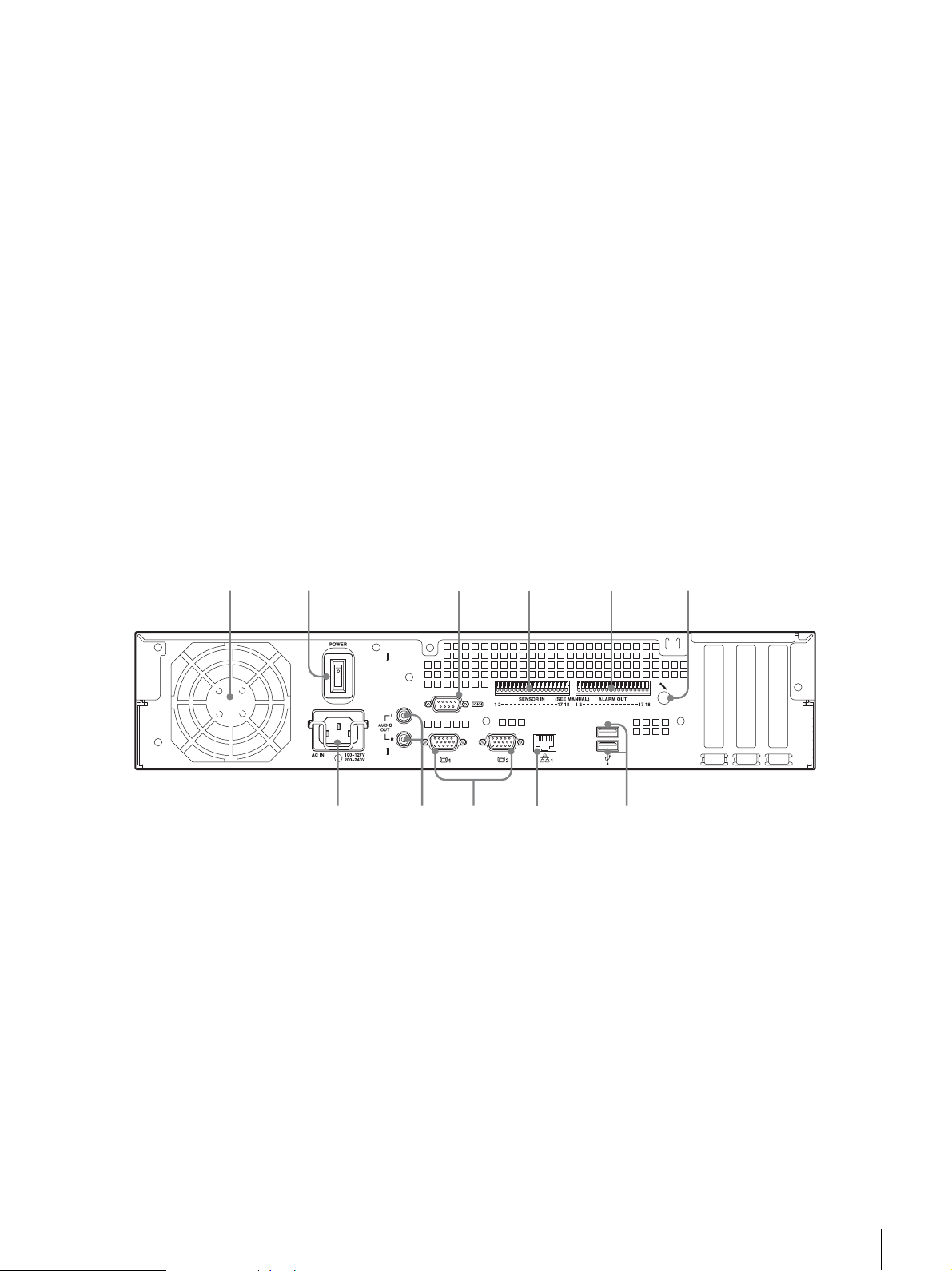
Rear
9q
0q
q
q
NSR-100/50
231 654 7 8
f
A Fan
Take care not to obstruct the fan grille. If the grille is obstructed, heat may build
up in the unit, leading to damage and/or fire.
B Power switch
Press the switch in the a position to turn on the unit.
C Video output connector
Use this connector to output video to a peripheral video device, such as a VCR.
The displayed images are the same as those for monitor connector 1.
D S-video output connector
Use this connector to output video to a peripheral video device equipped with
an S-video connector.
The displayed images are the same as those for monitor connector 1.
E Serial connector (RS-232C)
Use this connector to connect the control line of the uninterruptible power
supply (UPS).
F Sensor input connector
Use this connector to connect the sensor input lines.
For connection details and wiring diagrams for sensor inputs, see the “I/O Port”
(page 170).
d
s
a
G Alarm output connector
Use this connector to connect the alarm output lines.
For connection details and a wiring diagram for alarm output, see the “I/O Port”
(page 170).
H Audio input connector*
Use this connector to input audio from a peripheral audio device, such as a
microphone.
I SCSI connector*
Use this connector to connect a peripheral SCSI device.
Chapter 1 Introduction
11
Page 12
NSR-25
7890q
J USB connector
Use this connector to connect a USB keyboard, mouse, USB flash memory or
the RM-NS10 remote control unit to the NSR.
K LAN connectors (1 to 3)
Use these connectors to connect 10 Base-T, 100 Base-TX, or 1000 Base-T
network cables to the NSR.
NIC1: Network cameras
NIC2: Remote Clients
NIC3: External storage devices**
L Monitor connectors (1 and 2)
Use these connectors to connect a monitor.
M Audio output connectors (L and R)
Use these connectors to output audio to a peripheral audio device.
N Power supply connector
Use this connector to connect the power cord.
* This feature is not currently supported.
** External storage devices may not be supported depending on the software version.
For details, consult your dealer.
21 43 5 6
a
A Fan
Take care not to obstruct the fan grille. If the grille is obstructed, heat may build
up in the unit, leading to damage and/or fire.
B Power switch
Press the switch in the a position to turn on the unit.
C Serial connector (RS-232C)
Use this connector to connect the control line of the uninterruptible power
supply (UPS).
D Sensor input connector
Use this connector to connect the sensor input lines.
For connection details and wiring diagrams for sensor inputs, see the “I/O Port”
(page 170).
Chapter 1 Introduction
12
Page 13

E Alarm output connector
Use this connector to connect the alarm output lines.
For connection details and a wiring diagram for alarm output, see the “I/O Port”
(page 170).
F Audio input connector*
Use this connector to input audio from a peripheral audio device, such as a
microphone.
G USB connector
Use this connector to connect a USB keyboard, mouse, USB flash memory or
the RM-NS10 remote control unit to the NSR.
H LAN connectors
Use these connectors to connect 10 Base-T, 100 Base-TX, or 1000 Base-T
network cables to the NSR.
I Monitor connectors (1 and 2)
Use these connectors to connect a monitor.
J Audio output connectors (L and R)
Use these connectors to output audio to a peripheral audio device.
K Power supply connector
Use this connector to connect the power cord.
* This feature is not currently supported.
Chapter 1 Introduction
13
Page 14

System Requirements
The hardware required in order to use this recorder are as follows.
• Sony network cameras
Contact your dealer for details about compatible Sony network cameras.
• Monitor
• USB keyboard
• USB mouse
• Network switch
• 1000Base-T/100Base-TX/10Base-T cable
• CF (CompactFlash) card or USB memory device
1) For details about monitors supported by the NSR, contact your retailer.
The following “Generic” type monitors can be selected.
Frequency is indicated at the end of each line.
- Generic LCD Display; LCD Panel 1024×768; 40-70
- Generic LCD Display; LCD Panel 1280×1024; 50-75
- Generic LCD Display; LCD Panel 1600×1200; 60
- Generic CRT Display; Monitor 1024×768; 50-70
- Generic CRT Display; Monitor 1280×1024; 50-90
- Generic CRT Display; Monitor 1600×1200; 50-90
The following resolutions can be specified.
- XGA (1024×768)
- SXGA (1280×1024)
- UXGA (1600×1200)
2) Use a USB keyboard with a cable. However, keys other than the standard may not
function. Wireless or infrared USB keyboards may also not function properly.
3) Use a USB mouse with a cable. However, three-button or wheel mice may not
function properly. Wireless or infrared USB mice may also not function properly.
4) Required when backing up system information such as logs.
- For CF, use a card that has been formatted in advance with VFAT.
- For USB memory, use a device that supports general USB Mass Storage Class
specifications.
- CF cards are not compatible with the NSR-25.
1)
2)
3)
4)
Chapter 1 Introduction
14
Page 15
Initial Configuring the
Overview
Configuration Flow
System
When you first start the NSR, the system configuration window automatically
appears. Refer to the section below and configure the necessary settings.
Initial configuration Modification
Turn on the
The system configuration window
automatically appears.
NSR.
Chapter
2
See “System Configuration”
System Wizard (page 16).
See below for
additional settings
The NSR restarts automatically.
Logon screen
For further configuration
See below for additional settings
Monitoring windw
Modify the system settings. (page 25)
Chapter 2 Initial Configuring the System
15
Page 16

Initial configuration settings
• Language
•EULA
• Keyboard Layout
• Time Zone
•Day and Time
•Network Device
• Monitor Model
• Video Settings (only the NSR-100/50)
•Host Name
Additional settings
•NTP
•SNMP
•UPS
Note
You can also modify the settings that you configured during the initial
configuration. For details, see “Modifying the System Configuration” (page
25).
System Configuration (First Time: Basic Initial Setup)
Basic Configuration
When the NSR starts for the first time, you must perform the following
procedure.
Caution
The remainder of this manual uses illustrations and screens of the NSR-100/50.
1
Connect the USB keyboard and USB mouse to the unit, and turn on the
power.
The following screen appears, and a progress bar for hardware startup
appears.
Chapter 2 Initial Configuring the System
16
Page 17
Then the following screen appears, and a progress bar for software startup
appears.
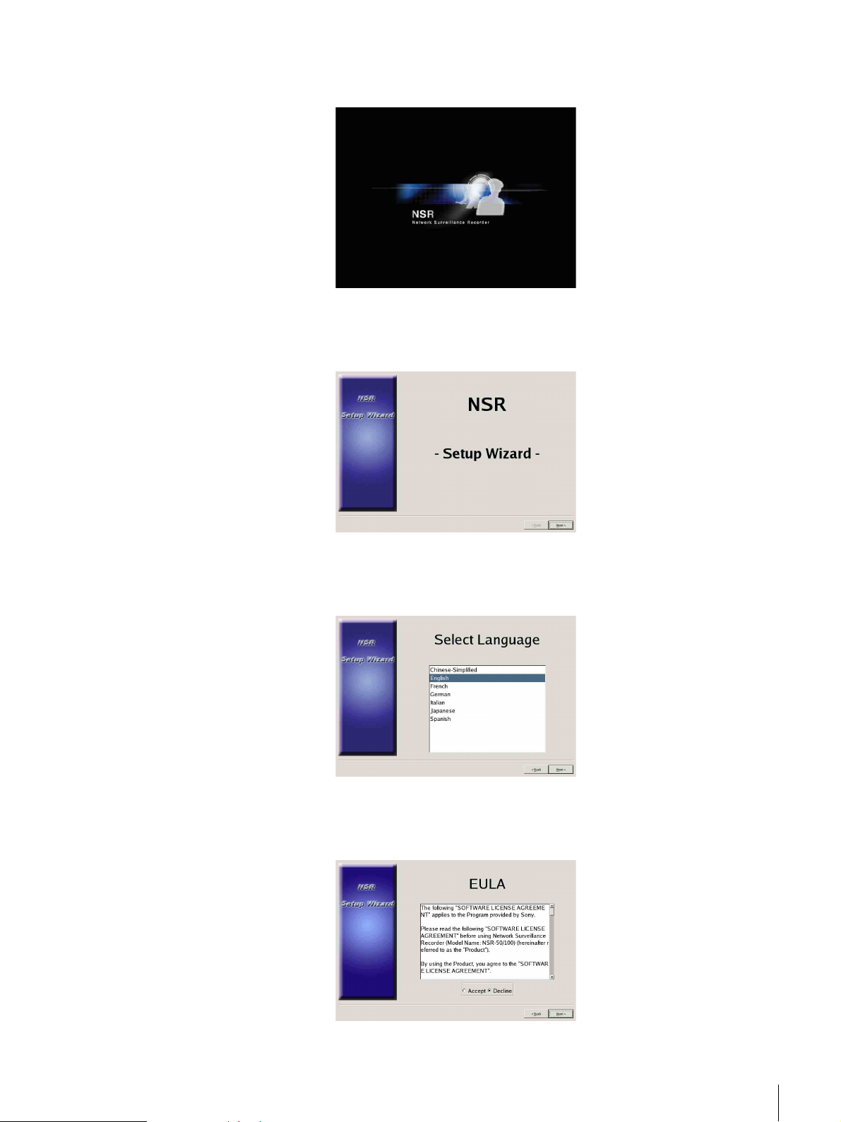
The unit starts and the system settings screen (Setup Wizard) appears.
2
Click [Next].
The [Select Language] screen appears.
3
Select the desired display language from the list, and then click [Next].
The [EULA] screen appears.
4
Read the user license agreement, click [Accept], and then click [Next].
The [Keyboard Layout] screen appears.
Chapter 2 Initial Configuring the System
17
Page 18
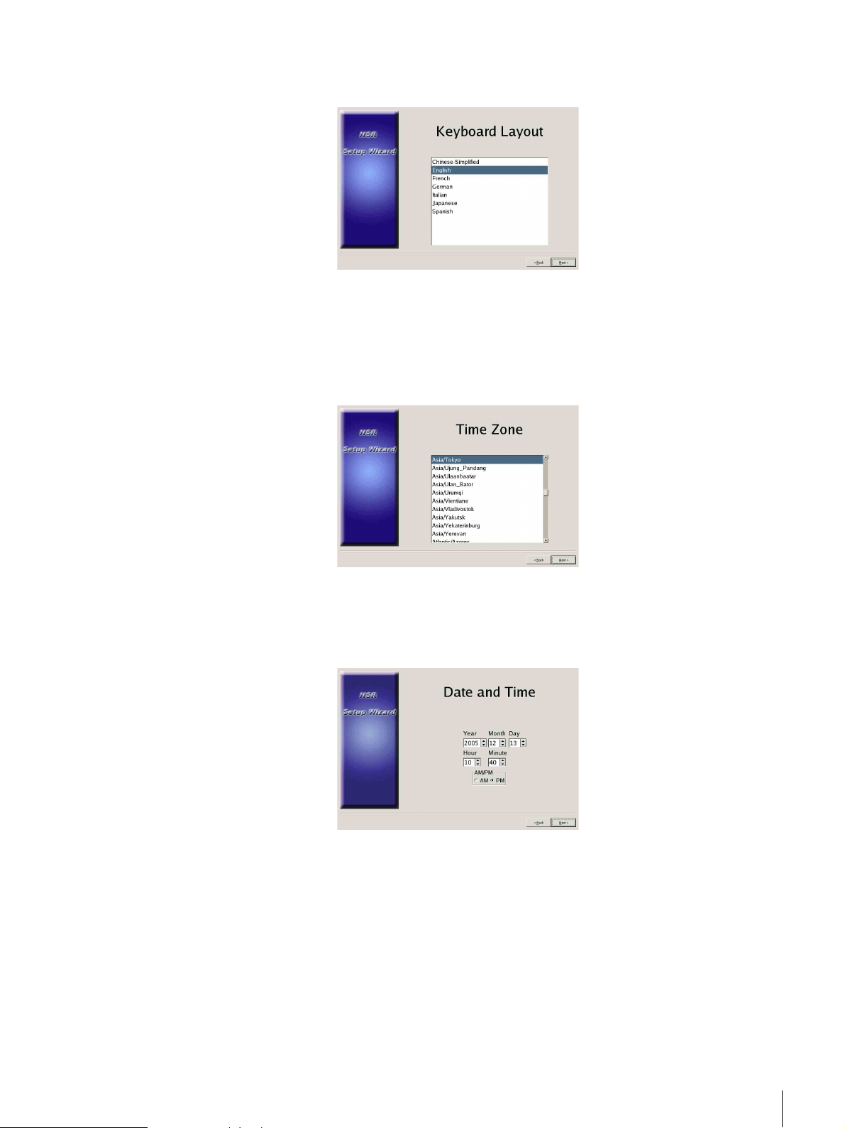
5
Select the type of USB keyboard connected to the unit from the list, and then
click [Next].
The [Time Zone] screen appears.
6
Select the desired time zone from the list, and then click [Next].
* There is no option for enabling or disabling summer time. If you select a time
zone in which time is adjusted for summer time, the time is adjusted for summer
time automatically.
The [Date and Time] screen appears.
7
Verify the date and time, and configure the correct date and time if
necessary, then click [Next].
The [General Network Setting] screen appears.
Chapter 2 Initial Configuring the System
18
Page 19
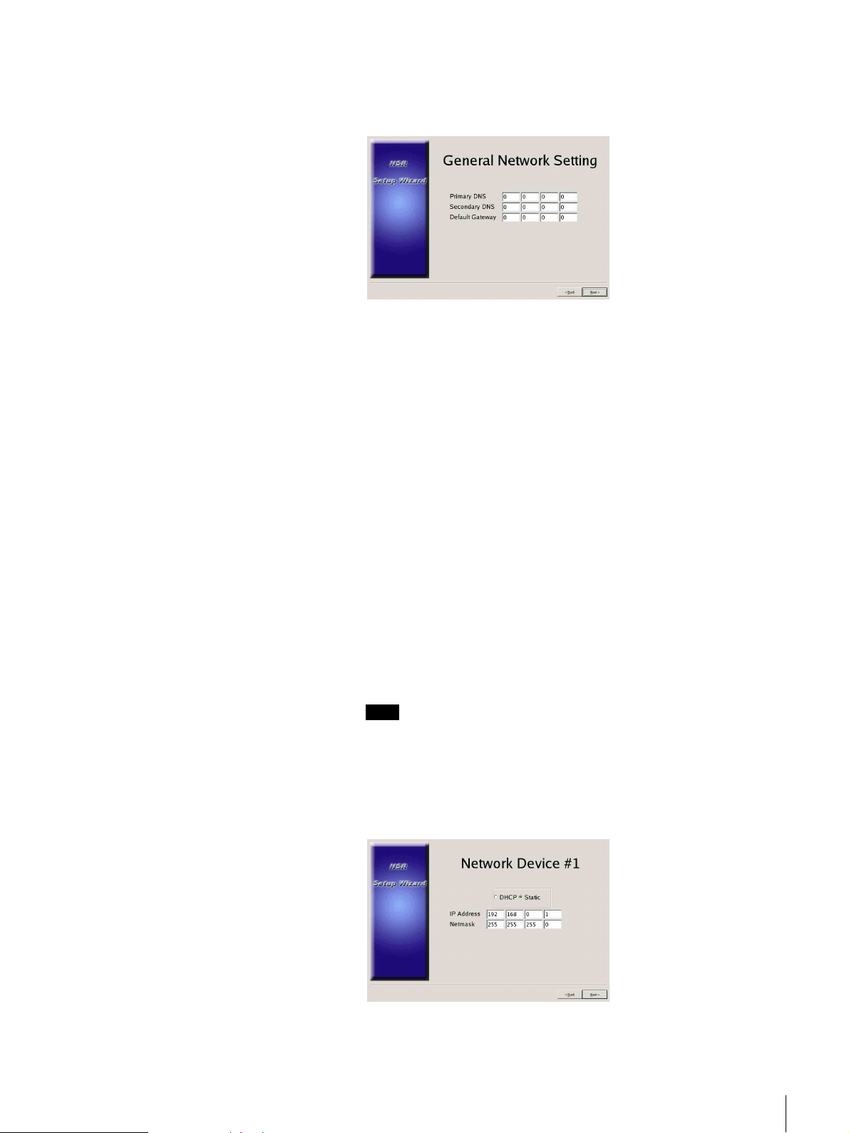
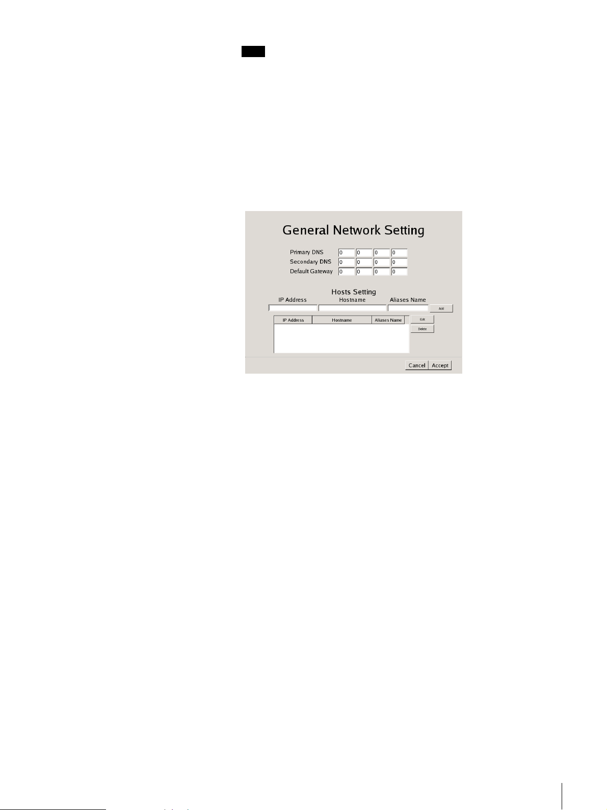
8
Perform the following steps to configure the network settings.
(1) Enter an IP address for each server in the [General Network Setting]
screen, and click [Next].
Primary DNS
Enter the primary DNS (Domain Name Server) IP address.
When there is no primary DNS or one is not necessary, do not enter an
IP address.
Secondary DNS
Enter the secondary DNS IP address.
When there is no secondary DNS or one is not necessary, do not enter
an IP address.
Default Gateway
Enter the default gateway IP address.
When only the local network is used or connection to other networks is
not necessary, do not enter an IP address.
The [Network Device #1] screen appears.
(2) Configure the [Network Device] settings for each of the LAN ports.
When using the NSR-100/50, configure the settings for each of the
three LAN ports (LAN1, LAN2, and LAN 3).
When using the NSR-25, configure the settings for the single LAN port
(LAN1).
Note
When using the NSR-100/50, connect the following devices to each of
the LAN ports.
LAN1: Network cameras
LAN2: Remote clients
LAN3: External storage devices (This may not be supported depending
on the software version. For details, consult your dealer.)
Chapter 2 Initial Configuring the System
19
Page 20
When using a DHCP server to configure address settings
automatically
Select [DHCP].
When configuring addresses manually
(1) Select [Static].
(2) Enter the following information.
IP Address
Enter the desired IP address.
Caution
• Before you enter the desired IP address, make sure that it is not
already otherwise used on the network. Entering an IP address
already in use may lead to erratic operation of the unit, but no
error messages appear to indicate the fact.
• Because of IP address attribution rules, setting an invalid
address such as the ones below is not allowed.
Example: 224.0.0.0 to 255.255.255.255
0.0.0.0
127.0.0.1, etc.
Netmask
Enter the subnet mask address.
Note
The default settings for network devices are as follows.
IP Address: 192.168.[0/1/2]*.1
Netmask: 255.255.255.0
* The settings for each of the network devices #1, #2, and #3 (only
network device #1 for the NSR-25).
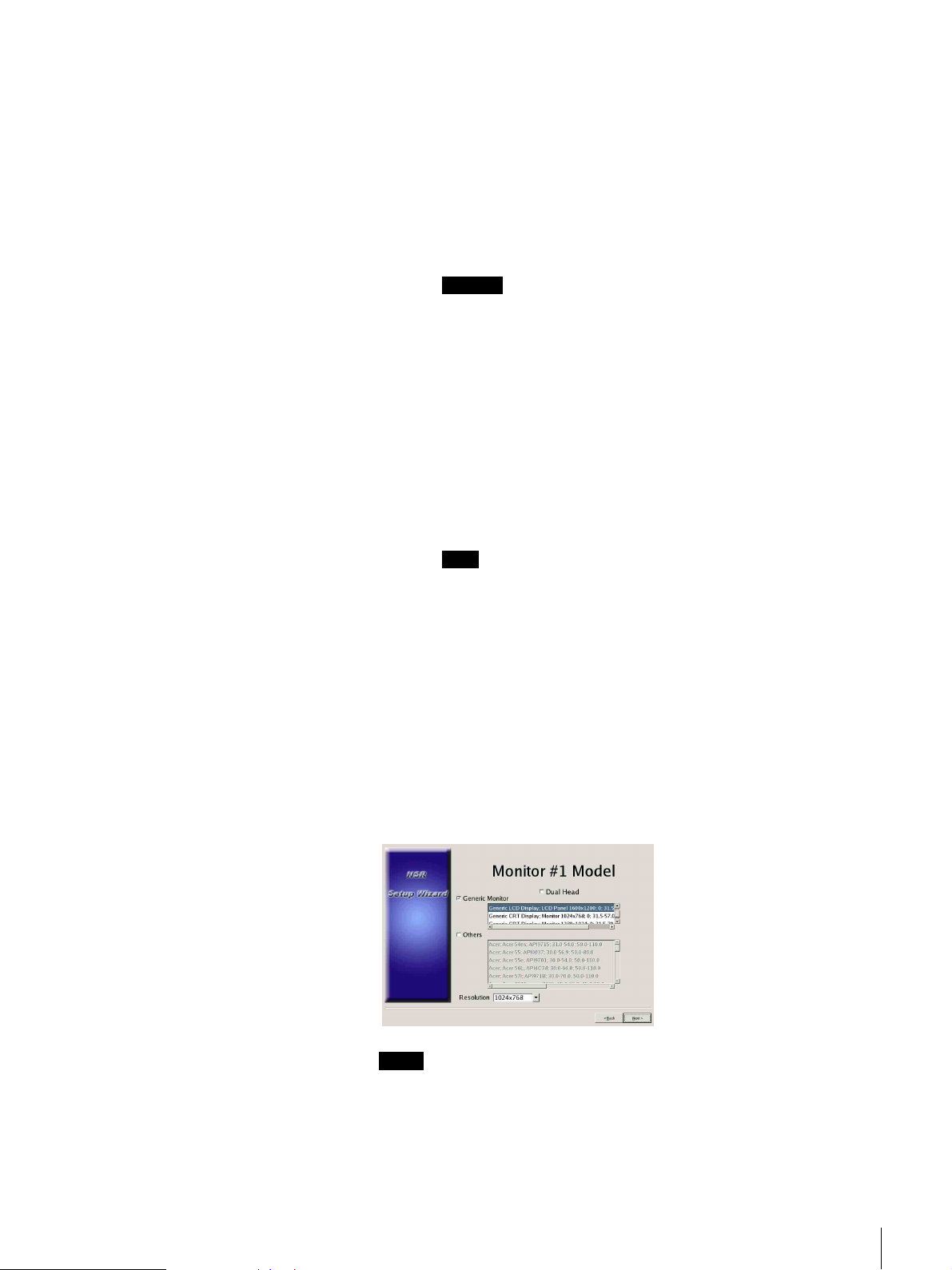
The [Monitor Model] screen appears.
9
Perform screen size settings depending on each monitor port, and then click
[Next].
When two monitors are connected, clicking [Dual Head] displays the
second monitor configuration screen.
Select the appropriate monitor type and resolution (pixels) for your monitor.
Notes
• The default setting for monitors is as follows.
Generic LCD Display; LCD Panel 1600
Resolution 1024
×768
×1200; 31.5-90; 60
• Most monitors will operate with [Generic Monitor], but you can select
[Others] as required.
Chapter 2 Initial Configuring the System
20
Page 21
Caution
When configuring settings for the second monitor, the second monitor must
be connected when the NSR restarts.
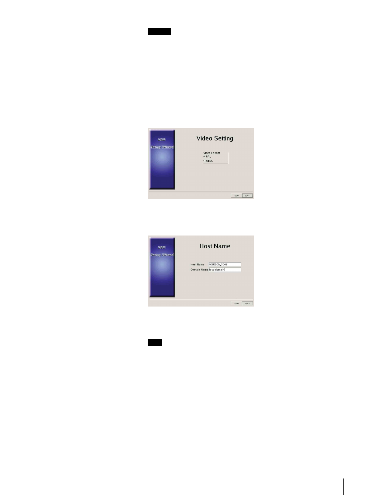
When using the NSR-100/50, the [Video Setting] screen appears. Proceed
to step 10.
When using the NSR-25, the [Host Name] screen appears. Proceed to step
11.
10
Select the appropriate video format, depending on your region, [NTSC] or
[PAL], and then click [Next].
* This screen only appears when using the NSR-100/50.
The [Host Name] screen appears.
11
Perform settings for each item, and then click [Next].
Host Name
Enter the host name.
Note
Use only alphanumeric characters, underscores (_), and hyphens (-).
Domain Name
Enter the network domain name according to your network.
Example: xxx.sony.co.jp
When you do not register the NSR to the DNS, you do not need to change
the default settings.
The [Summary] screen appears.
Chapter 2 Initial Configuring the System
21
Page 22
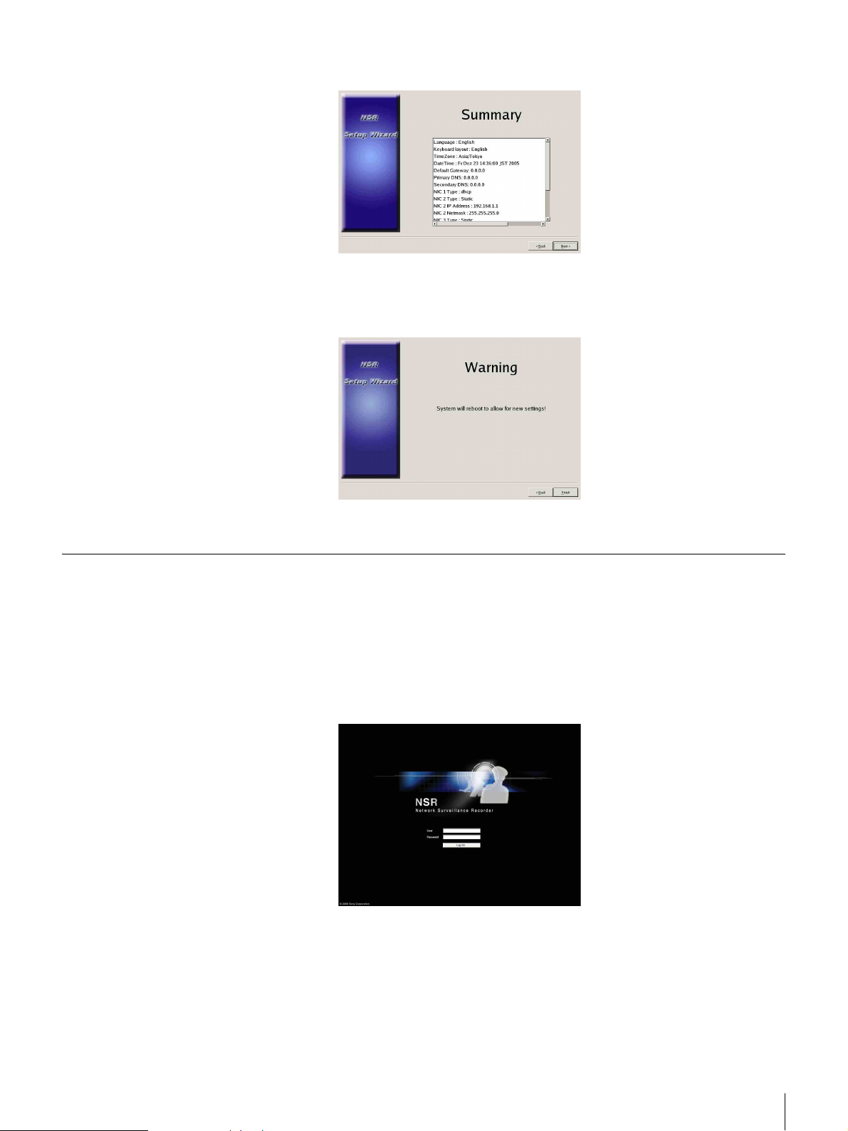
12
Confirm the settings and then click [Next].
The [Warning] screen appears.
13
Click [Finish].
The NSR restarts automatically.
Camera IP Address Configuration and Registration to NSR
After restarting, the logon screen appears.
Next, configure the IP addresses for cameras and register them to the NSR.
1
Enter your user name and password, and then click [Log On].
Default User Name: admin
Default Password: admin
The Camera screen appears in the Configuration window.
Chapter 2 Initial Configuring the System
22
Page 23
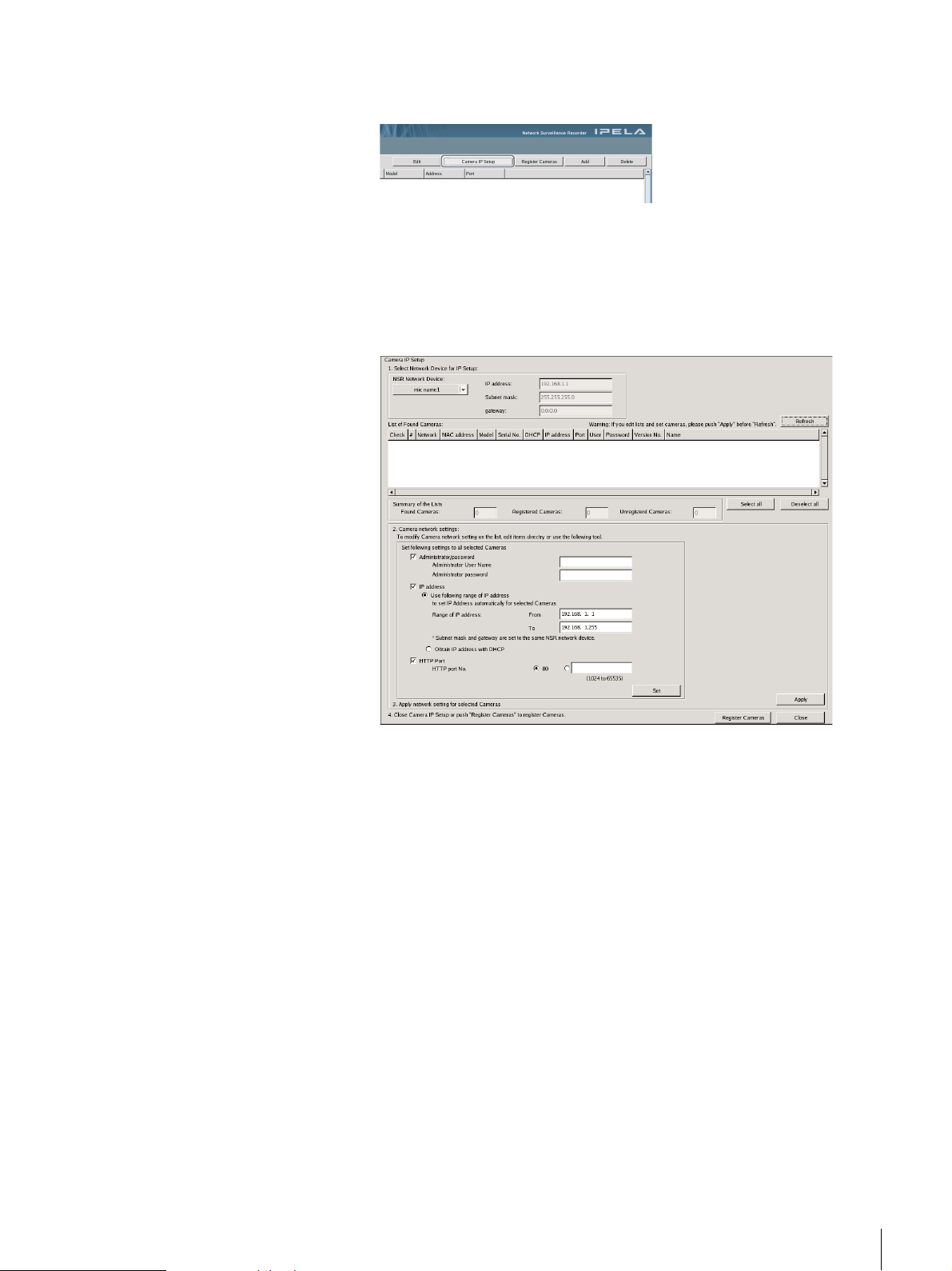
2
Click [Camera IP Setup].
If the IP addresses for the cameras have already been set, click [Register
All] and proceed to Step 5.
The Camera IP Setup window appears.
3
Perform the following settings.
In the Camera IP Setup window, you can search for cameras on the same
network by MAC address and configure their IP addresses all at once.
(1) Select the network to search in the field labeled “1. Select Network
Device for IP Setup.”
Normally, Network 1 is selected as the camera network, and a list of
the cameras found appears in the “Found Camera List.” The check
boxes of all found cameras are selected.
(2) Enter the following information in the field labeled “2. Set Camera
network setting.”
• The user name and password of the camera you are configuring
settings for.
• The range of IP addresses on the same network (default: 0 to 254) for
which to perform automatic assignment.
• The http port number (default: 80) for communicating with cameras.
* If there is a fixed range of IP addresses that can be assigned to
cameras, make sure to specify the correct range.
Chapter 2 Initial Configuring the System
23
Page 24
(3) Click [Set].
The information you entered is reflected in the “Found Camera List.”
IP addresses are assigned within the specified range. Because the list
does not expand to compensate if there are not enough IP addresses,
make sure the list is set correctly by directly changing addresses in the
list as needed.
At this stage, the settings have not yet been applied to the camera.
(4) Click [Apply].
This configures the camera settings using the information developed in
the list.
It takes a few moments for the settings to complete.
4
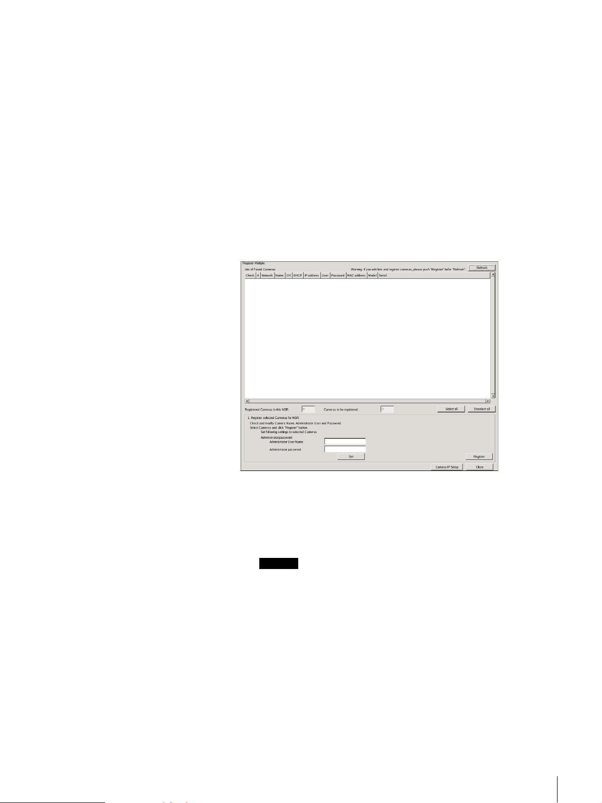
When the settings for each camera are complete, click [Register All].
The Register Cameras window appears.
5
Perform the following settings.
In the Register Cameras window, a list of cameras that have not been
registered to the NSR appears with the check box for each selected.
(1) Verify the number of cameras selected for registration in the column
labeled “Cameras to be registered”, and confirm the user name and
password for each camera.
Caution
The user name and password for the cameras are not set by default. You
can set the user name and password for the selected cameras
simultaneously under “Register selected Cameras for NSR.”
(2) Click [Register].
The selected cameras are registered to the NSR.
* By clicking [Camera IP Setup], you can also return to the previous
Camera IP Setup window.
6
When registration is complete, click [Close].
The Configuration window returns to the Camera screen. The registered
cameras are listed.
Chapter 2 Initial Configuring the System
24
Page 25

7
If necessary, configure the individual settings for each camera.
For details about settings, see “Settings” (page 83), Chapter 5.
8
When you have verified the settings for each camera, click [Monitoring].
The “Monitoring” window appears.
By clicking [Configure], you can switch to the “Configuration” screen and
make changes to the settings.
Modifying the System Configuration
1
Click [System] at the top left of the Monitoring window, and then click
[Setup Menu] in the [Setup Menu] screen that appears.
The [Setup Menu] screen appears.
Chapter 2 Initial Configuring the System
25
Page 26
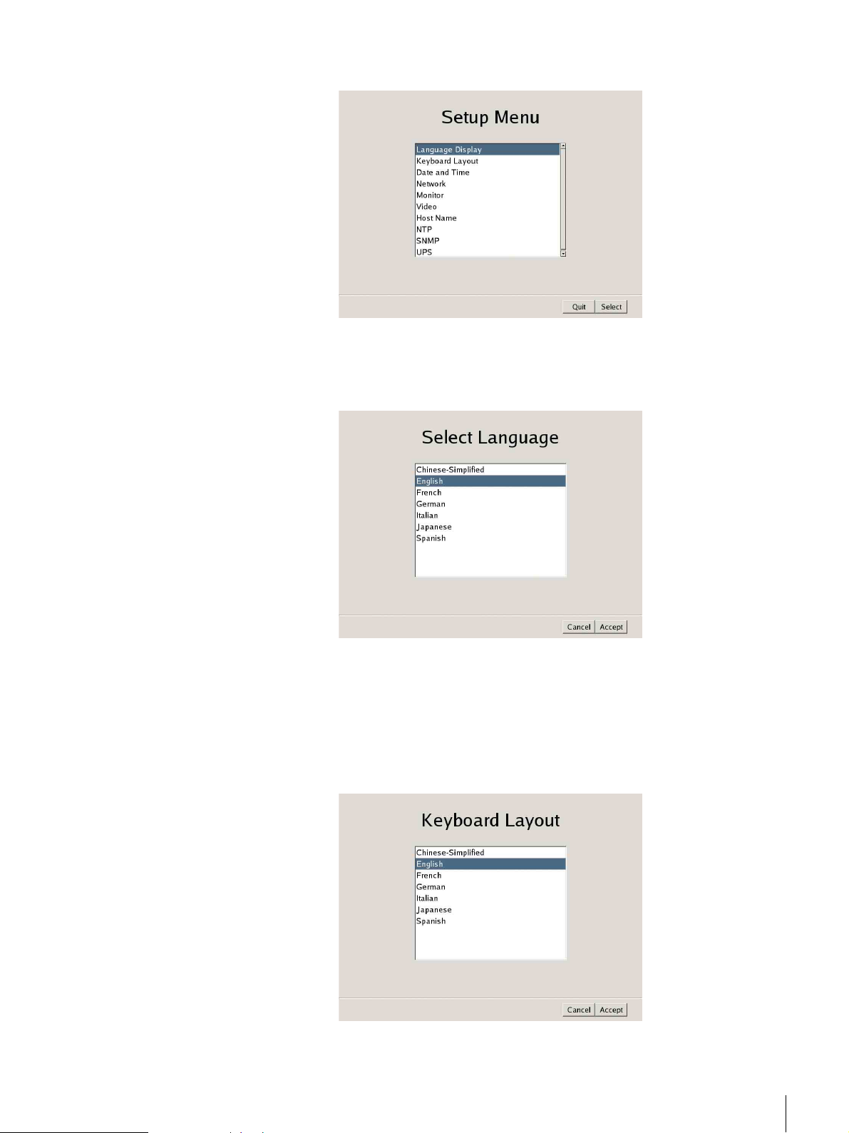
2
Select the [Language Display], and then click [Select].
The [Select Language] screen appears.
3
Select one of the languages displaying in the screen, and then click
[Accept].
When you click [Accept], the [Setup Menu] screen returns.
4
Select the [Keyboard Layout], and then click [Select].
The [Keyboard Layout] screen appears.
5
Select the language for the USB keyboard connected to the NSR, and then
click [Accept].
When you click [Accept], the [Setup Menu] screen returns.
Chapter 2 Initial Configuring the System
26
Page 27
6
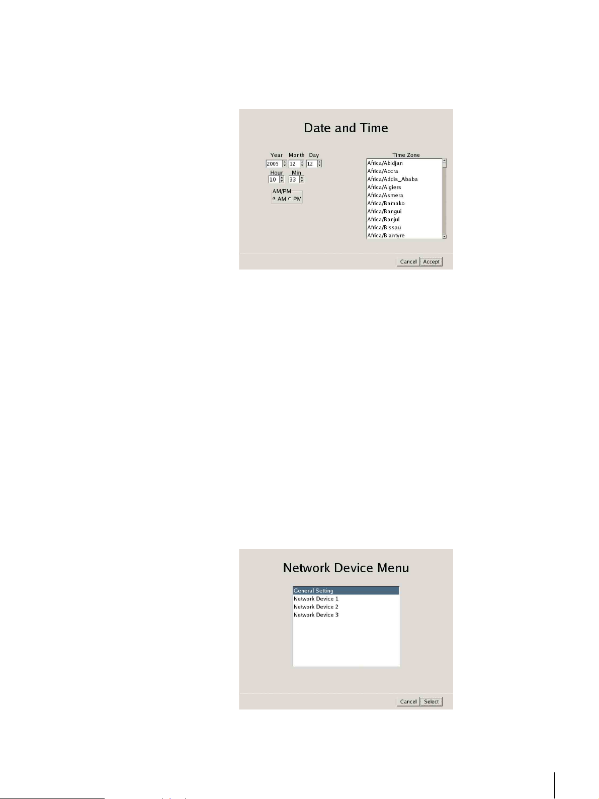
Select the [Date and Time], and then click [Select].
The [Date and Time] screen appears.
7
Configure the date and time, and then click [Accept].
Year/Month/Day
Enter the date.
Hour/Min
Enter the correct time, and then select [AM] or [PM].
Time Zone
Select the time zone where you are located.
* There is no option for enabling or disabling summer time. If you select a time
zone in which time is adjusted for summer time, the time is adjusted for summer
time automatically.
When you click [Accept], the [Setup Menu] screen returns.
8
Select the [Network], and then click [Select].
The [Network Device Menu] screen appears.
9
Select the desired network device, and then click [Select].
The network settings consist of a “General Network Setting” and a
“Network Device” that provides LAN ports.
When using the NSR-25, only “Network Device 1” can be set.
Chapter 2 Initial Configuring the System
27
Page 28
Note
When using the NSR-100/50, connect the following devices to each of the
LAN ports.
LAN 1: Network cameras
LAN 2: Remote clients
LAN 3: External storage devices (This may not be supported depending on
the software version. For details, consult your dealer.)
10
To configure general settings, click [General Setting] and then [Select].
The [General Network Setting] screen appears.
11
Configure each item below, and then click [Accept].
Primary DNS
Enter the IP address for the primary DNS (Domain Name Server). Skip this
entry if a primary DNS is not available or not required.
Secondary DNS
Enter the IP address of the secondary DNS. Skip this entry if a secondary
DNS is not available or not required.
Default Gateway
Enter the IP address of the default gateway. Skip this entry when only a
local network is used or when connections to other networks are not
required.
Hosts Setting
If a host name needs to be registered in the hosts file, enter the IP address
and corresponding host name, and then click [Add] to add it to the list.
12
To configure each LAN port, click [Network Device] and then [Select].
Configure the “Network Device” settings for each of the LAN ports.
The [Network Device] screen appears.
Chapter 2 Initial Configuring the System
28
Page 29
13
Configure each item, and then click [Accept].
Configure the settings depending on your network.
When using a DHCP server to configure address settings
automatically
Select [DHCP].
When wanting to configure addresses manually
(1) Select [Static].
(2) Enter the following information.
IP Address
Enter the desired IP address.
Notes
• Before you enter the desired IP address, make sure that it is not already
used on the network. Entering an IP address already in use may lead to
erratic operation of the unit, but no error messages appear to indicate
the fact.
• Because of IP address attribution rules, setting invalid addresses such
as the ones below are not allowed.
Example: 224.0.0.0 to 255.255.255.255
0.0.0.0
127.0.0.1, etc.
Netmask
Enter the subnet mask address.
Note
The default settings for network devices are as follows.
IP Address:192.168.[0/1/2]*.1
Netmask: 255.255.255.0
* The settings for each of the network devices #1, #2, and #3 (only network
device #1 for the NSR-25).
Chapter 2 Initial Configuring the System
29
Page 30
Route Setting
Click if you need to configure a route to another network.
Make the following settings on the [Route For Network Device 1] screen
that appears.
(1) Enter the network address, gateway, and net mask, and then click
[Add] to add the new network to the list.
For details, consult the network administrator.
(2) Click [Accept].
When you click [Accept], the [Setup Menu] screen returns.
14
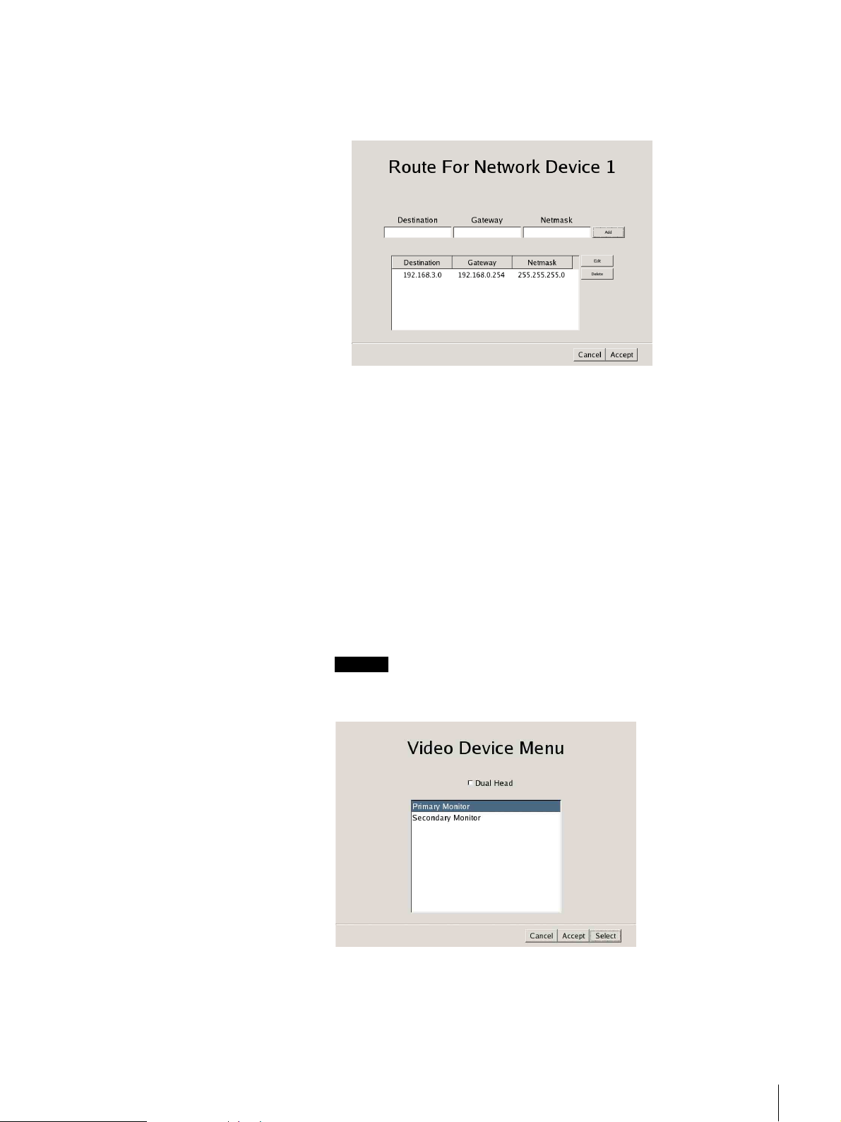
Select the [Monitor], and then click [Select].
The [Video Device Menu] screen appears.
15
Select the desired monitor, and then click [Select].
When two monitors are connected, the second monitor can be configured if
[Dual Head] is clicked.
Caution
When configuring settings for the second monitor, the second monitor must
be connected when the NSR restarts.
The [Monitor Model] screen appears.
Chapter 2 Initial Configuring the System
30
Page 31

16
Select the model of monitor connected to the NSR and its resolution, and
then click [Accept].
Note
The default setting for monitors is as follows.
Generic LCD Display; LCD Panel 1600x1200; 31.5-90;60
Resolution 1024×768
When you click [Accept], the [Setup Menu] screen returns.
17
When using the NSR-100/50, select [Video], and then click [Select].
The [Video Setting] screen appears.
18
Select the [PAL] or [NTSC] video output format, and then click [Accept].
(Only the NSR-100/50)
When you click [Accept], the [Setup Menu] screen returns.
19
Select the [Host Name], and then click [Select].
The [Host Name] screen appears.
20
Enter the host name and the domain name of the NSR, and then click
[Accept].
Chapter 2 Initial Configuring the System
31
Page 32

Note
Use only alphanumeric characters, underscores (_), and hyphens (-).
When you click [Accept], the [Setup Menu] screen returns.
21
Select the [NTP], and then click [Select].
The [NTP Setting] screen appears.
22
When you want to acquire the current time from an NTP server, select
[Enable], and enter the NTP server IP address, then click [Accept].
When you do not want to acquire the current time from an NTP server,
select [Disable] and then click [Accept].
When you click [Accept], the [Setup Menu] screen returns.
23
Select the [SNMP], and then click [Select].
The [SNMP Menu] screen appears.
Chapter 2 Initial Configuring the System
32
Page 33

24
To configure an SNMP community, select [Agent]; to configure SNMP
traps, select [Traps], and then click [Select].
25
Configure each item below in the following screen, and then click [Accept].
When you select [Agent]
Enable
Select this check box to enable the SNMP Agent function.
Disable
Select this check box to disable the SNMP Agent function.
Community
Enter the name of the SNMP community in the text box.
Contact
Enter the administrator e-mail address.
Location
Enter the location of the NSR.
Note
You can acquire the “System” and “SystemUptime” MIB-2 objects that
appear with the “.1.3.6.1.2.1.1” and “.1.3.6.1.2.1.25.1.1” object IDs.
Chapter 2 Initial Configuring the System
33
Page 34

When you select [Traps]
Enable
Select this check box to enable SNMP traps.
Disable
Select this check box to disable SNMP traps.
Host IP Address
Enter the trap’s host IP address.
Community
Enter the SNMP community name in the check box.
Temperature Events
Select this option to be notified of irregular temperatures of the unit.
Voltage Events
Select this option to be notified of irregular voltage activity.
UPS Events
Select this option if you are connected to a UPS and that you want to be
notified of UPS power failures.
Power Events
Select this option to be notified when the NSR shuts down.
Fan Events
Select this option to be notified of irregular fan activity.
RAID Events
Select this option to be notified of RAID group rebuilds.
HDD Events
Select this option to be notified of hard disk malfunctions.
When you click [Accept], the [Setup Menu] screen returns.
26
Select the [UPS Settings], and then click [Select].
The [UPS Settings] screen appears.
Chapter 2 Initial Configuring the System
34
Page 35

27
Configure each item below, and then click [Accept].
Enable
Select this check box when you use a UPS.
If you select this check box, select your UPS from the list.
Disable
Select this check box when you do not use a UPS.
Power off In XXX Seconds
Enter the time before shutting down the unit after a power interruption is
detected.
28
When the settings are complete, click [Quit].
The completed system settings are saved to DiskOnModule (DOM).
While the settings are being saved, a progress bar appears. When the process
is complete, [OK] is enabled.
Caution
If the network settings have been modified, a network restart is performed.
Be aware that during this period recording may not be possible for several
seconds.
29
Click [Reboot] in the System Menu to restart the NSR manually.
Chapter 2 Initial Configuring the System
35
Page 36

Reconstructing Data Volume (Changing RAID Types) (Only the NSR-100/50)
RAID constructions that can be set as data volumes differ depending on the
model number of the NSR.
* RAID is not available for the NSR-25.
Model Type Approximate
NSR-100 RAID-5 670 GB Yes Yes
RAID-1+0 450 GB Yes
RAID-0 900 GB None
NSR-50 Spanning 430 GB Partial Yes
RAID-1 210 GB Yes
Caution
• Be aware that all settings information and recorded images are deleted when
reconstructing data volume.
• When changing the settings is necessary, make sure to change the RAID
construction beforehand.
1
Connect the USB keyboard and USB mouse to the NSR, and turn on the
power.
capacity
Redund-
ancy
Default
setting
The following screen and a progress bar for hardware startup appear.
2
Press F12 on the keyboard while the progress bar is displayed.
The screen similar to the following appears.
Example: For the NSR-50 (there are 3 menu items for the NSR-100)
* The number of devices and their names may differ from the following example
screen.
Boot Menu
1.QSI DVD+/–RW SDW-0826
2. WDC WD2500JD-22HBC0-(S1)
3. WDC WD2500JD-22HBC0-(S2)
4. PQI IDE DiskOnModule-(SM)
<Enter Setup>
Chapter 2 Initial Configuring the System
36
Page 37

3
Use the arrow keys on the keyboard to select [IDE DiskOnModule], and
press Enter.
Startup from DiskOnModule (DOM) begins.
After startup, the DOM menu appears.
4
Click the third item from the top, [Clean System Restore with Changing
RAID Types].
The RAID Type selection screen appears.
5
Select the RAID Type, and click [OK].
Example: For the NSR-50
The confirmation screen appears.
Chapter 2 Initial Configuring the System
37
Page 38

6
Click [OK].
RAID reconstruction for data volume and full system restoration begins.
This process can take up to about 5 hours. A progress bar appears during the
process.
When the process successfully completes, a notification screen appears.
Example: For an NSR-50 with RAID 1 selected
7
Press Enter after the process completes and the message [Press any key to
continue!] appears.
The screen returns to the DOM menu.
8
Click [Reboot].
The NSR reboots, and the Setup Wizard appears.
Chapter 2 Initial Configuring the System
38
Page 39

Overview
To perform the initial configuration
Basic Operation
This chapter presents NSR basics, such as how to log on to it, how to configure
the system settings, how to use the various windows, how to modify the
password, as well as how to turn the unit off and restart it.
For details on monitoring operations, see “Monitoring Live Images” (page 53).
For details on all the unit settings, see “Settings” (page 83).
For details on other functions, see the following chart.
Note
With two monitors connected to the NSR, you can perform settings and
monitoring operations on monitor 1 and hot spot monitoring on monitor 2.
Chapter
3
To monitor live images
Configuring the system
Registering cameras
Configuring cameras
Configuring camera advanced
settings
Controlling cameras (“Selecting the Live
Images” (page 59))
“Configuring the system” (page 16)
“Modifying the System Configuration” (page 25)
“Camera” (page 93)
“Camera” (page 93)
“Configuring the Advanced Settings of
Cameras” (page 101)
“Controlling Cameras” (page 60)
Chapter 3 Basic Operation
39
Page 40

To record
To play back recorded images
Manual recording
Scheduled recording
Triggered recording
Configuring Video Motion
Detection (Recorder)
Configuring sensor input
Configuring a Video Motion
Filter
“Playing Back Recorded Images” (page 65)
“Recording Live Images” (page 64)
“Recording Schedule” (page 135)
“VMD (Recorder)” (page 112)
“Sensor Input” (page 121)
“VMF” (page 114)
“Searching for Recorded Images to Play
Back” (page 68)
To use other functions
Monitoring audio from a
camera
Exporting recorded images
Configuring alarm outputs
Configuring monitors
Logging On to the NSR
Before you can use the NSR, you must first log on. Once you turn on the NSR,
the logon screen appears.
“Monitoring Audio From Cameras” (page 63)
“Exporting” (page 71)
“Alarm Output” (page 130)
“Monitor” (page 145)
1
At the rear of the NSR, press the power switch to the a position.
Chapter 3 Basic Operation
40
Page 41

NSR-100/50
NSR-25
The startup screen appears.
Notes
• About two seconds after you turn on the NSR, the fan starts emitting a
loud noise, but this is not a malfunction.
• If the NSR is not properly turned off, it may take some time for it to start
the next time you turn it on.
The logon screen appears.
Chapter 3 Basic Operation
41
Page 42

2
Enter your user name and password, and then click [Log On].
Note
By default, the first time you turn on the NSR, only the administrator is
registered on the system. The default administrator user name is as follows.
User name: admin
Password: admin
Basic Window Operations
This section presents an overview of the basic operations common in all
windows. For details about all the windows, see “Monitoring Live Images”
(page 53) and for details about all the settings, see “Settings” (page 83).
The NSR has two windows: the Monitoring window for monitoring images and
the Configuration window for configuring settings. Switch between them as
necessary by clicking the corresponding button at the top of the window.
Monitoring Window Configuration Window System Menu Screen
When you click [Monitoring]
The “Monitoring” window appears. In this window, you can monitor live
images or recorded images. To switch between the live images and recorded
images, click the display that you want to switch, and then use the [LIVE]
and [PLAYBACK] buttons in the lower-left corner of the window.
Chapter 3 Basic Operation
42
Page 43

For details about monitoring, see “Monitoring Live Images” (page 53).
Select a camera.
Use these buttons to switch between live images and recorded images.
When you click [Configuration]
The “Configuration” window appears.
Select the settings that
you want to change.
These buttons change depending the
available operations for the current screen.
Depending on your selections, various
settings and information appear.
Chapter 3 Basic Operation
43
Page 44

When you click [System]
The “System Menu” screen appears. You can click the buttons to perform
basic system-related operations.
Changing the Password
The NSR password is essential to your system’s security. We recommend that
you modify the default password after logging on to the NSR for the first time,
and then to guard your password carefully.
Notes
• You can only change the user name of the user logged on currently.
• When operating by remote control, enter only numbers for a password.
• Passwords can contain up to 15 characters.
1
Click [System] at the top of the window.
The “System Menu” screen appears.
2
Click [Change Password].
The “Change Password” screen appears.
Chapter 3 Basic Operation
44
Page 45

3
Change the necessary settings.
User
Enter the user name used when logging on to the NSR.
Old Password
Enter the current password.
New Password
Enter your new password.
Confirm New Password
Enter your new password again to confirm.
4
Click [OK].
The password modification is applied.
Logging Off From the NSR
1
Click [System] at the top of the window.
The “System Menu” screen appears.
2
Click [Log Off].
A message appears to confirm whether to log off.
Chapter 3 Basic Operation
45
Page 46

Locking the NSR
3
Click [Log Off].
You are logged off from the NSR and the “Logon” screen appears.
To log on to the NSR again, simply type your user name and password, and
then click [Log On].
You can temporarily lock the screen in its current state. Use the lock if, for
example, you need to leave your seat during operation.
1
Click [System] at the top of the window.
The “System Menu” screen appears.
2
Click [Lock].
When operations are locked, the following screen appears.
To unlock operations, enter your user name and password, and click
[Unlock].
Note
Operations can be unlocked by a logged-in user or a Level 4 user.
Chapter 3 Basic Operation
46
Page 47

Shutting Down and Restarting the NSR
Make sure that you shut down and restart the NSR from the “System” screen.
1
Click [System] at the top of the window.
The “System Menu” screen appears.
2
Click [Shutdown] or [Reboot].
A confirmation message appears, prompting you to confirm the operation.
3
Click [Shutdown] or [Reboot].
The NSR shuts down or restarts.
Note
Under normal conditions, the NSR shuts down or restarts after a few
minutes. If the NSR does not shut down or restart after several minutes, shut
it down manually by pressing the power switch located on the rear of the
unit in the a position for more than five seconds.
Saving and Restoring Configuration Data
You can save NSR configuration data to external media or restore the
configuration data to the NSR.
Saving Configuration Data
Caution
Be aware that the following information is not saved:
• Records
• Network settings, date and time information, and other basic initial setup
items (such as those set in “Basic Configuration” (page 16))
•Logs
1
Click [System] at the top of the window.
The “System Menu” screen appears.
Chapter 3 Basic Operation
47
Page 48

2
Click [Save Configuration Data].
The “Save Configuration Data” screen appears.
3
Select the save destination, enter a name for the configuration data file, and
then click [OK].
Restoring Configuration Data
Caution
• Be aware that the following information is not restored:
• The settings on the external storage are not restored, and must be reconfigured
to the same values as when the data was saved.
• Information cannot be restored if the model or the first two digits of the
current software version (e.g., the “a.b” of version “a.b.c”) differ from what
they were when the configuration data was saved.
During backup of the configuration data, a progress bar appears. When
backup is complete, the configuration data is saved.
Note
When the configuration data finishes saving, the following directory and
file are created at the save destination:
• A directory named “YearMonthDayHourMinuteSecond”
• A file named “YearMonthDayHourMinuteSecond.itm”
Ex) If the data is saved at 12:34:56 on January 1, 2007, a directory named
“20070101123456” and a file named “20070101123456.itm” are
created.
• Records
• Network settings, date and time information, and other basic initial setup
items (such as those set in “Basic Configuration” (page 16)
•Logs
Chapter 3 Basic Operation
48
Page 49

• When configuration data is restored, any recording operations that were in
progress automatically stop. If you set a recording schedule, recording restarts
automatically after data is restored. If you were performing manual recording,
you must restart manual recording again after data is restored.
1
Click [System] at the top of the window.
The “System Menu” screen appears.
2
Click [Restore Configuration Data].
The “Restore Configuration Data” screen appears.
3
Select the location of the configuration data and the desired data, and then
click [Restore].
A message appears notifying the user that this operation will require an NSR
reboot.
4
Click [OK].
During restoration, a progress bar appears. When restoration is complete,
the NSR reboots and the configuration data is restored.
Chapter 3 Basic Operation
49
Page 50

Exporting Log Files
You can save NSR log files to external media.
Log files include information such as system logs, alarm logs, and setting
information.
1
2
Click [System] at the top of the window.
The “System Menu” screen appears.
Click [Export Log Files].
The “Export Log Files” screen appears.
3
Select the save location for the log files, enter a comment for the log data,
and then click [OK].
The log files are saved.
Chapter 3 Basic Operation
50
Page 51

Starting Up the Setup Menu
1
Click [System] at the top of the window.
The “System Menu” screen appears.
2
Click [Setup Menu].
The “Setup Menu” screen appears.
Setup data is automatically backed up to DiskOnModule (DOM) when the
Setup Menu is exited.
Chapter 3 Basic Operation
51
Page 52

While the settings are being backed up, a progress bar appears. When the
process is complete, [OK] is enabled.
Chapter 3 Basic Operation
52
Page 53

Monitoring Live Images
Overview
In the “Monitoring” window, you can watch the live images from the cameras
connected to the NSR, playback recorded images, control connected cameras,
or export recorded images.
Note
With two monitors connected to the NSR, you can perform monitoring, settings,
searches and all other operations on monitor 1 and hot spot monitoring on
monitor 2.
Monitoring Window Functions and Operation
Chapter
4
This section explains how to use every function and button when monitoring
live images or playing back recorded images. For details about how to control
cameras connected to the NSR, see “Controlling Cameras” (page 60).
Chapter 4 Monitoring Live Images
53
Page 54

Monitoring Window (Monitor 1)
DABCEF
KLMNOPQ
R
G
H
I
0
A Monitor windows
You can display live images and play back recorded images in each monitor
window.
To monitor live images, click the window in which you want to monitor live
images and then click [LIVE].
t “Selecting the Live Images” (page 59)
To play back a recorded image, click the monitor window in which you
want to play it back and then click [PLAYBACK].
t “Playing Back Recorded Images” (page 65)
For details on monitor windows, see “Monitor Window” (page 57).
B [Export] button
Click this button to export recorded images as files to an external storage
media.
t “Exporting” (page 71).
C [Full Screen] button
Display the current monitor layout (monitor window arrangement) over the
full screen.
Switching to full-screen display hides the operation buttons and other items.
To return to normal-screen display, press the Esc key.
D Monitor layout selection
You can select a registered monitor layout or monitor sequence.
Click [V] and then select a monitor layout name or monitor sequence name
from the list that appears.
t “Monitoring in Sequence Mode” (page 62), “Registering a New Monitor
Layout” (page 146), and “Adding a Monitoring Sequence” (page 149)
Chapter 4 Monitoring Live Images
54
Page 55

E [Sequence] button
Perform a sequence operation.
This button is enabled when a monitor sequence is selected for 4 Monitor
layout selection.
t “Monitoring in Sequence Mode” (page 62)
F Option window (Auxiliary function area)
Click [V] and then select an item from the list that appears to display
information about that item or perform the camera control operations.
Any of the following items can be selected.
1. Camera Control : Allows you to control the cameras.
2. Recording Status: Displays a list of the cameras currently recording.
3. Recording List : Displays a list of recent recorded images.
4. Alarm Log : Displays logs related to alarms.
5. System Log : Displays logs related to system information and
errors.
6. Alarm Output : Displays the current alarm output status.
7. Sensor Input : Displays the current sensor input status.
8. VMD (Recorder): Displays the current motion detection settings
information.
9. Manual Trigger : Displays actions you can execute manually.
* For details on these items, see “Option Window (Auxiliary Function
Area)” (page 77).
G Recording button
Start recording. You can also select multiple monitor windows and then
start recording.
However, you can only start recording for monitor windows for which
[LIVE] is selected. Recording cannot be started for monitor windows for
which [PLAYBACK] is selected.
t “Recording Live Images” (page 64)
H Recording stop button
Stop recording. You can also select multiple monitor windows and then stop
recording.
This button is only enabled when a monitor window in which recording is
being performed is selected.
t “Recording Live Images” (page 64)
I [ALARM] lamp
This lamp turns on when an alarm occurs.
When the [4. Alarm Log] item is displayed in the Option window, the lamp
turns off because the logs are considered to have been checked.
The lamp turns on for a few seconds if an alarm occurs while the [Alarm
Log] is displayed. To turn the lamp off, click [Refresh] in the [Alarm Log].
J [ERROR] lamp
This lamp turns on when an error occurs.
When the [5. System Log] item is displayed in the Option window, the lamp
turns off because the logs are considered to have been checked.
The lamp turns on for a few seconds if an error occurs while the [System
Log] is displayed. To turn the lamp off, click [Refresh] in the [System Log].
K [Search] button
Switch to the Search screen to search for recorded images.
t“Searching for Recorded Images to Play Back” (page 68)
Chapter 4 Monitoring Live Images
55
Page 56

L Quick search button
You can specify a date and time for the playback start position of a recorded
image.
t “Quick Search” (page 67)
M Play speed
Adjust the play speed for the recording by clicking [V] and then selecting a
play speed from the list that appears.
t “To search for recorded images” (page 68)
N Play speed
Control playback of the recorded images currently playing back. These
buttons cannot be used for live images during monitoring.
: Moves to the beginning of the recorded image. If the
current recorded image is already at the beginning, moves
to the beginning of the previous recorded images.
: Plays back the recorded image in the reverse direction.
: Pauses playback.
: Plays back the recorded image in the forward direction.
: Moves to the start of the next recorded image.
The following buttons are for operations while playback is paused. Pressing
either of these buttons during playback pauses the playback.
: Moves back one frame from the current position.
: Moves forward one frame from the current position.
O Volume
Adjust the volume of the sound output from the NSR. The sound of the
selected camera (or camera selected last if multiple cameras are selected) is
output.
P Mute button
Mute all sound output from the NSR. Click again to turn the sound back on.
Q Camera list (camera selection)
Select a camera whose images you wish to display in the monitor window.
t “To monitor the images of another camera” (page 59)
R [LIVE] button/[PLAYBACK] button
Click [LIVE] to monitor live images in the selected monitor window and
click [PLAYBACK] to play back recorded images in the selected monitor
window.
t “Selecting the Live Images” (page 59) and “Playing Back Recorded
Images” (page 65)
One of these buttons will light to indicate the current status when a monitor
window is selected.
If multiple monitor windows are selected and there is a combination of Live
and Playback statuses, the button that indicates the status of the monitor
window selected last will light. When multiple monitor windows are
selected, the statuses of all selected monitor windows become Live if
[LIVE] is clicked and the statuses of all selected monitor windows become
Playback if [PLAYBACK] is clicked.
Chapter 4 Monitoring Live Images
56
Page 57

Monitoring Window (Monitor 2)
12 3
When two monitors are connected to the NSR, a monitor layout specified as
1×1, 2×2, or 3×3 is displayed on the monitor connected to monitor connector 2.
You can use monitor 2 as a hot spot monitor.
The image displayed is the same as that of the monitor window selected in
monitor 1. However, if there is a sensor input or motion detection, the image
from the corresponding camera is displayed.
When two monitors are connected, the NSR operates as follows:
• Selected images, or images from cameras with a sensor input or motion
detection event, are displayed in available monitor windows sequentially,
from top left to top right, and then bottom left to bottom right.
• Images that are already displayed in a monitor window do not appear again in
a different monitor window.
Screen of Monitor 1 Screen of Monitor 2
Monitor Window
Notes
• You cannot control a camera for a monitor window directory from monitor 2.
• You cannot perform configuration operations from monitor 2.
• When images are displayed on monitor 2, the performance of monitor 1 may
decrease.
4
5
76
A Camera name
Indicates the name of the camera.
Chapter 4 Monitoring Live Images
57
Page 58

B Status
Indicates the recording type (MANUAL REC, ALARM REC, or NORMAL
REC) during recording.
Indicates the playback status (PAUSE, etc.) and play speed (+1x, –0.2x,
etc.) during the playback of recorded images (“+” appears for the play speed
when playback is in the forward direction and “–” appears for the play speed
when playback is in the reverse direction).
C Bandwidth
Indicates the bandwidth used for transferring images via the network
connection.
D Number of frames received
Indicates the camera image capture rate.
E Number of frames displayed
Indicates the rate at which camera images are refreshed on the monitor.
F Live/Recorded image
Displays a live image or a recorded image. Video Motion Detection
(Recorder) object frames and VMF (Video Motion Filter) object and filter
frames also appear.
G Time
Indicates the current date and time when live images are being monitored or
recorded, or the recording date and time when recordings are being played
back.
You can configure the display format in the Configuration window.
t “General” (page 84)
Notes
• When there is a sensor input or a specified sensor input, or a motion detection
or VMF package alarm occurs, the image of the corresponding camera is
displayed in the monitor window set for the hot spot.
• If there is sensor input or a motion detection or VMF package alarm occurs, a
red frame appears around the corresponding camera images.
To switch the monitor window layout
If you double-click a monitor window, the monitor layout switches to a 1 x 1
display of the images from the camera assigned to that monitor window.
However, the display is not changed if 1 x 1 is disabled for the monitor layout
currently in use.
Note
Double-clicking the monitor window again returns the monitor layout to the
original layout.
However, once the monitor layout is switched to a 1 x 1 display, if it is switched
again by an action, monitoring sequence, or monitor layout change, then doubleclicking the monitor window again does not return the monitor layout to the
original layout.
To hide various information
You can hide various information in a monitor window by right-clicking the
monitor window and then clearing the check boxes in the menu that appears.
This change is not reflected and saved in the monitor layout settings of the
Configuration window.
Chapter 4 Monitoring Live Images
58
Page 59

About selecting multiple monitor windows
You can select multiple monitor windows by clicking monitor windows while
pressing the Shift key.
Note
If you perform an operation that cannot be performed on multiple monitor
windows after you select multiple monitor windows, the operation is only
performed on the monitor window selected last.
Selecting the Live Images
You can monitor live images in any of the monitor windows. In the
“Monitoring” window, you can also control a selected camera.
Selecting the Live Images
1
Select the monitor window in which to display the live images.
You can select multiple monitor windows by clicking monitor windows
while pressing the Shift key.
2
Click [LIVE] at the bottom left of the window.
Click [LIVE].
The live images appear in the selected monitor window.
To monitor the images of another camera
1
Select a monitor window.
2
Click [V] on the camera list at the bottom left of the window and then click
a camera name from the list that appears.
While the list is displayed, you can also select a camera by pressing the
number key indicated on the left side of the camera name and then pressing
the Enter key.
Select a camera.
Chapter 4 Monitoring Live Images
59
Page 60

Controlling Cameras
The camera of the monitor window is switched.
Notes
• You can also select multiple monitor windows and then switch cameras.
• Selecting another camera in the camera list does not change the camera setting
for “Monitor” of the Configuration window.
You can monitor live images while controlling the camera.
1
Select a monitor window of your choice, and display the images from the
camera you wish to control.
Camera control is only enabled for cameras supported by the network. In
addition, when multiple monitor windows are selected, the camera
associated with the last monitor window selected is targeted for control.
2
Click [V] at the top right of the screen for the Option window and then click
[1. Camera Control].
The Camera Control panel appears.
3
Using the buttons on the control panel, you can control the selected camera.
Chapter 4 Monitoring Live Images
60
Page 61

Pan/Tilt
Move the camera up, down, left, or right.
PRESET
Recall a registered preset.
ZOOM
Adjust the zoom toward the “W” side for a wide angle, and the “T” side for
telephoto.
Clicking between the “W” and the “T” zooms to the absolute value.
FOCUS
Select [AUTO] when you want the focus to always be adjusted
automatically.
Clicking [–] or [+] cancels auto focus and enables you to adjust the focus
manually. Adjust the focus toward the [–] side to focus on subjects that are
near, and toward the [+] side to focus on subjects that are farther away.
When you pan, tilt, or zoom the camera, [AUTO] is selected automatically.
BRIGHT
Select [AUTO] when you want the brightness level to always be adjusted
automatically.
Clicking [–] or [+] cancels auto brightness and enables you to adjust the
brightness level manually. Adjust the brightness level toward the [+] side
for bright images, and the [–] side for dark images.
When you pan, tilt, or zoom the camera, [AUTO] is selected automatically.
To performing pan, tilt, and zoom operations in monitor windows
You can perform pan, tilt, and zoom operations in a monitor window without
using the pan, tilt, and zoom controls on the Camera Control panel.
Direct pan and tilt
Click a point within a monitor window while pressing the Ctrl key to move the
camera so that the selected point is in the center.
Area zoom
Drag the mouse within a desired area in a monitor window while pressing the
Ctrl key to display a red frame, and then release the mouse button to zoom in on
that area.
Chapter 4 Monitoring Live Images
61
Page 62

To the mouse wheel to zoom
Rotate the mouse wheel in a forward direction while pressing the Ctrl key to
zoom in and rotate the mouse wheel in a backward direction while pressing the
Ctrl key to zoom out.
Mouse operations in monitor windows
Use your mouse and your keyboard simultaneously to control certain camera
functions.
Shortcut keys Operations
Ctrl + left click Moves so that the selected point becomes
Ctrl + left click and drag A red frame appears and the image within
Ctrl + wheel (forward) Zoom in
Ctrl + wheel (backward) Zoom out
About presets
The NSR enables you to configure camera settings beforehand and then register
them as presets. For details on registering presets, see “Preset” (page 109) of
“Advanced Configuration.”
If you click [V] for preset and then click a preset from the list that appears, the
camera is set in accordance with the settings configured for the preset.
the center.
the frame is magnified to fill the window when
the mouse button is released.
Note
While the list is displayed, you can also select a preset by pressing the number
key indicated on the left side of the preset name and then pressing the Enter key.
Monitoring in Sequence Mode
Sequence mode is a function for displaying multiple monitor layouts in
sequence during a specified time period.
To use sequence mode, a monitor sequence needs to be registered in advance.
For details on registering monitor sequences, see “Adding a Monitoring
Sequence” (page 149) of “Advanced Configuration.”
1
Click [V] for monitor layout selection at the top center of the window and
then click a sequence name from the list that appears.
2
Click [Sequence] at the top center of the window.
Sequential operation begins.
Click [Sequence] again to end the sequence operation.
Chapter 4 Monitoring Live Images
62
Page 63

Displaying Camera Images in the Hot Spot Monitor Window
If a monitor window is set as the hot spot, the same images from another monitor
window you click will also be displayed in the hot spot monitor window.
For details on setting a hot spot, see “Monitor” (page 145) of “Advanced
Configuration.”
Note
When two monitors are connected to the NSR, monitor 2 normally functions as
the monitor for the hot spot. For details on configuring the second monitor, see
step 15 (page 30) of “Modifying the System Configuration.”
Displaying Images in the Hot Spot Monitor Window When There is Sensor Input or an Alarm
If a sensor input or a motion detection or VMF package alarm occurs, the images
of the corresponding camera are displayed in the hot spot monitor window.
While the images are displayed, a red frame emphasizes the monitor window to
which the corresponding camera is assigned.
Monitoring Audio From Cameras
You can monitor audio input from cameras that support audio input.
1
Select the monitor window for which you want to monitor audio.
The audio from the camera assigned to the selected monitor window is
output.
If multiple monitor windows are selected, the audio of the camera selected
last is output.
2
Use the slider at the bottom right of the window to adjust the volume.
Muting Sound From Cameras
Click the Mute button at the bottom left of the window to mute.
Mute button
Chapter 4 Monitoring Live Images
63
Page 64

When sound is muted, sound is not output for any monitor windows you select.
To cancel mute, click the Mute button again.
Recording Live Images
You can record the images currently being captured by a camera.
Starting Recording
1
Select the monitor window of the live images you want to record.
You can select multiple monitor windows by clicking monitor windows
while pressing the Shift key.
2
If a live image is not displayed, click the [LIVE] button at the bottom left of
the window.
3
Click the record button at the bottom right of the window.
Stopping Recording
Record button
Recording starts.
Notes
• Recording continues even if you change the monitor layout.
• Cameras currently recording are displayed in Recording Status of the Option
window.
1
Select the monitor window for which you want to stop recording.
2
Click the recording stop button.
Recording stop button
A message appears based on the recording type to confirm whether to stop
recording.
3
Click [OK].
Recording stops.
Chapter 4 Monitoring Live Images
64
Page 65

Selecting a Camera From Recording Status and Stopping Recording
You can select a camera that is recording but not displayed in the current
monitor layout from Recording Status in the Option window, assign it to any
monitor window, and then stop recording.
Not only can you stop recordings in progress started manually, but also
scheduled recordings.
1
Select any one of the monitor windows.
2
Click [V] at the top right for the Option window and then select [2.
Recording Status].
Recording Status appears.
3
Double-click the name of the camera for which you want to stop recording.
The specified camera is assigned to the monitor window selected in Step 1.
If multiple monitor windows are selected, the camera is assigned to all
monitor windows selected.
4
Click the recording stop button.
Recording stops for the specified camera.
Playing Back Recorded Images
Play back saved recorded images.
Selecting a Monitor Window and Starting Playback
You can select a monitor window displayed in the current monitor layout and
then start playback of recorded images.
1
Select the monitor window in which you want to play back the recorded
images.
You can select multiple monitor windows by clicking monitor windows
while pressing the Shift key.
Chapter 4 Monitoring Live Images
65
Page 66

2
Click [PLAYBACK] at the bottom left of the window.
[PLAYBACK] button
The selected monitor window enters the playback state and displays the first
frame of the last images recorded by the camera assigned to that monitor
window. If multiple monitor windows are selected, all the selected monitor
windows enter the playback state.
Note
If a camera is switched from the recording to the playback state, the last
frame of recorded images available for playback is displayed.
3
Use the playback buttons to control playback.
For details on the functions of the playback buttons, see “Monitoring
Window (Monitor 1)” (page 54).
Note
If multiple monitor windows are selected, playback starts simultaneously in
all selected monitor windows.
To change the play speed
4
Select another monitor window and repeat Steps 1 to 3 to play back
recordings from the camera assigned to that monitor window.
1
Select the monitor window playing the recording for which you want to
change the play speed.
You can select multiple monitor windows by clicking monitor windows
while pressing the Shift key.
2
Click [V] for “PLAY SPEED” at the bottom center of the window and then
click the desired play speed.
The following play speeds can be selected.
0.1x, 0.2x, 0.5x, 0.75x, 1x, 2x, 5x, 10x, 20x, 50x, or 100x
PLAY SPEED
The play speed of the selected monitor window changes.
Notes
• If you select a monitor window playing recorded images, the current play
speed is indicated by “PLAY SPEED.”
• If multiple monitor windows playing recorded images are selected and
then Steps 1 and 2 above are performed, the play speeds of all the selected
monitor windows change.
Chapter 4 Monitoring Live Images
66
Page 67

Quick Search
To perform a quick search, specify a date and time for the playback start position
of a recorded image.
1
Select the monitor window in which you want to play back the recorded
images.
You can select multiple monitor windows by clicking monitor windows
while pressing the Shift key.
2
Enter the date and time in the date and time boxes and then click [GO].
The playback start position moves to a position on or near the specified date
and time.
If there is no recorded image for the selected monitor on the specified date
and time, the first frame of the next recorded images after the specified date
and time is displayed.
Note
If there are multiple recorded images for the specified date and time, a
selection is made according to the following priority order: alarm recording
> manual recording > normal recording.
3
Click or to move the playback position frame by frame
when you want to specify a playback start position more minutely.
Selecting From Recording List
You can select the recording of a monitor window not displayed in the current
monitor layout from Recording List in the Option window, assign it to any
monitor window, and then start playback.
1
Select any one of the monitor windows.
2
Click [V] at the top right for the Option window and then select [3.
Recording List].
Recording List appears.
Up to 300 recordings appear in order in the Recording List, starting with the
most recent recording based on the date and time of the last update.
Chapter 4 Monitoring Live Images
67
Page 68

3
Double-click the recorded image you want to play back.
The first frame of the specified recorded image is displayed in the monitor
window selected in Step 1.
Note
If multiple monitor windows are selected, the frame is displayed in the
monitor window selected last.
4
Use the playback buttons to control playback.
Searching for Recorded Images to Play Back
You can search for a recorded image by specifying a date and time or event. You
can also specify a recording type (normal recording, alarm recording, or manual
recording). In addition, with alarm recording, you can also specify a trigger.
When recording metadata, you can perform searches by applying a Video
Motion Filter (VMF), consisting of your motion detection and object detection
criteria.
To search for recorded images
1
Select any monitor window.
2
Click [Search] at the bottom right of the window.
The “Search” screen appears.
[Search] button
Chapter 4 Monitoring Live Images
68
Page 69

3
Enter the search criteria.
Camera
Select a camera.
REC Type
Select this option to search by recording type.
When this is selected, you can search for a recorded image by specifying the
recording type.
Normal
Search for a recorded image for which recording was started by a
schedule.
Alarm
Search for a recorded image for which recording was started by an
alarm. When [Alarm] is selected, the search conditions can be
narrowed down by specifying an alarm type with the [Trigger] option
that appears to the left. The types of alarm that can be specified are
Device Input, System Input, VMD (Recorder), VMD (Camera), and
VMF.
Manual
Search for a recorded image for which recording was started
manually.
VMF
Select this option to apply a Video Motion Filter (VMF), consisting of your
motion detection criteria, to recorded metadata and search for
corresponding recordings.
A VMF search can be performed either by using a preconfigured VMF
package or by configuring a VMF package for temporary use.
• When using a preconfigured VMF package, click [V] and select the VMF
package to use for searching from the list that appears.
• When configuring a temporary VMF package for searches, click [V] and
select [Temporary Package] from the list that appears. Next, click [Edit]
and configure the temporary VMF package on the screen that appears.
Note
[VMF] cannot be selected when “All” is selected for [Camera].
Chapter 4 Monitoring Live Images
69
Page 70

From/To
Specify the period to search for recorded images.
The search collects any recorded images that fall within this specified
period.
4
Click [Search].
While searching, the following screen appears.
When the search finishes, a list of search results appears.
Notes
• When a VMF search in progress is cancelled, the results of the search up
to that point are displayed.
• During a VMF search, a confirmation message indicating the search may
take a while appears along with a progress bar.
To play back recorded images from the search results
You can select and play back a recorded image from the search results list.
The recording is played back in the monitor window selected before the Search
screen was opened.
1
Select the recorded image you want to play from the search results list.
For searches by recording type
The first frame of the selected recording image appears in the preview area.
Chapter 4 Monitoring Live Images
70
Page 71

For searches by VMF
At the moment an alarm is detected with the specified VMF package, the
image appears in the preview area.
2
Click [Playback].
The Search screen closes and the specified recorded image appears in a
paused state in the selected monitor window.
Exporting
Exporting Movies
3
Use the playback buttons to control playback.
Note
When a recording is selected for playback from a VMF search, NSR plays
back the first recording it finds within 10 seconds of the time selected.
You can export saved recorded images as files.
Movies are exported in a proprietary format (.cam file) and still images are
exported in JPEG format. You can play back exported movies with an
application that supports CAM file playback.
Notes
Multiple export processes cannot be performed simultaneously.
1
Click [Export] at the top center of the window.
If you want to export the recorded images currently playing, pause playback
before clicking [Export] (when multiple monitor windows are selected, the
last window to be selected is targeted for exporting).
When playback is paused, the following screen appears.
Otherwise, the “Movie Export - Record Search” screen appears. Go to step 3.
Chapter 4 Monitoring Live Images
71
Page 72

2
Select [Movie Export] and then click [OK].
The “Movie Export - Output” screen appears. Go to step 6.
3
Enter the search criteria.
Camera
Select a camera.
REC Type
Search for a recorded image by specifying the recording type.
Normal
Search for a recorded image for which recording was started by a
schedule.
Alarm
Search for a recorded image for which recording was started by an
alarm. When [Alarm] is selected, the search conditions can be
narrowed down by specifying an alarm type with the [Trigger] option
that appears to the left. The types of alarm that can be specified are
Device Input, System Input, VMD (Recorder), VMD (Camera), and
VMF.
Manual
Search for a recorded image for which recording was started
manually.
From/To
Specify the period to search for recorded images.
The search collects any recorded images that fall within this specified
period.
Chapter 4 Monitoring Live Images
72
Page 73

4
Click [Search].
The search results list appears.
5
Select the recorded images you want to export from the search results list
and then click [Select].
The “Movie Export - Output” screen appears.
6
Add the files for export to the [Files for Export] list.
Selected records
Displays the recorded images selected in the search results list.
When playback is paused, only the recorded images in the monitor window
targeted for exporting appear.
Files of records
Displays a list of the files included in the recorded image selected in the
[Selected records] list.
When playback is paused and a file is automatically added to the [Files for
Export] list, the subsequent file (or preceding file, if no subsequent file
exists) is selected when this list appears.
Export with Audio Data
Select this check box to export audio data with the recorded images.
An asterisk (*) will appear under the [Storage] column for recorded images
that include audio data.
Summary of File sizes (MB)
Displays the total size of all files included for the recording.
Files for Export
Displays a list of the files for export.
When playback is paused, files that include the date and time of the
currently paused image are automatically added.
When you select a file from the [Files of records] list and click [Add], the
file is added to this list.
When you select a file from this list and click [Delete], the file is deleted
from this list.
Chapter 4 Monitoring Live Images
73
Page 74

Capacity Requirement (MB)
Displays the amount of space required for all the files selected for export.
Output
Select the location to export the files for export. Click [V] and then select
Compact Flash, USB, or CD/DVD (only CD or USB memory for the
NSR-25) from the list that appears.
Status
Displays the status of the output location.
“Ready” is displayed for media which you can currently write on.
Available (MB)
Displays the available space on the output location.
7
Connect the media to use as the output location to the NSR.
8
Specify the media to use as the export location for [Output].
9
Make sure “Ready” is displayed for [Status] and then click [Export].
Exporting starts.
The Movie Export - Status screen is displayed for you to check the progress
during exporting.
Notes
• If there is insufficient space on the media, a warning message appears and
exporting stops.
• If you click [OK] during exporting, the Monitoring window is
redisplayed and exporting continues in the background.
• If you redisplay the Monitoring screen during exporting and then click
[Export], the “Movie Export - Status” screen appears.
• The capacity displayed for [Capacity Requirement (MB)] on the “Movie
Export - Output” screen is a rough estimate. Even if the capacity
displayed for [Available (MB)] is greater than that for [Capacity
Requirement (MB)], in rare cases the available space on the media may
be insufficient and exporting may fail.
• When exporting a recorded file to a CD or DVD, spaces ( ) included
within the file name are replaced with underscores (_).
• If a file is exported while being recorded, it may not play back properly.
To export records while they are recording, export files other than the
most recent.
Chapter 4 Monitoring Live Images
74
Page 75

Exporting Still Images
The following appears when exporting ends.
10
Click [OK].
The Movie Export - Status screen closes.
Export one scene of a recorded image as a still image file.
1
Select any monitor window and then play the recorded image containing the
scene you want to export.
2
Pause the recorded image at the scene you want to export.
Caution
Live images cannot be exported as still images.
3
Click [Export] at the top center of the window.
4
Select [Still Image Export] and then click [OK].
The following screen appears.
The “Still Image Export - Output” screen appears.
Chapter 4 Monitoring Live Images
75
Page 76

File name
Enter the file name.
If you enter a file name that already exists in the export location, the file may
be exported under a file name different from the one you enter.
Output
Select the location to which to export the files for export. Click [V] and then
select Compact Flash, USB, or CD/DVD (only CD or USB memory for the
NSR-25) from the list that appears.
Status
Displays the status of the output location.
“Ready” is displayed for media which you can currently write on.
Available (MB)
Displays the available space in the output location.
5
Connect the media to use as the output location to the NSR.
6
Enter a file name in the File name box.
7
Specify the media to use as the export location for Output.
8
Make sure “Ready” is displayed for [Status] and then click [Export].
Exporting starts.
The Movie Export - Status screen is displayed for you to check the progress
during exporting.
Notes
• If there is insufficient space on the media, a warning message appears and
exporting stops.
• If you click [OK] during exporting, the Monitoring window is
redisplayed and exporting continues in the background.
• If you redisplay the Monitoring screen during exporting and then click
[Export], the “Still Image Export - Status” screen appears.
The following appears when exporting ends.
9
Click [OK].
The Still Image Export - Status screen closes.
Chapter 4 Monitoring Live Images
76
Page 77

Option Window (Auxiliary Function Area)
In the Option window of the [Monitoring] window (monitor 1), you can display
the following information and perform camera control operations.
1. Camera Control : Allows you to control the cameras. (page 60)
2. Recording Status : Displays a list of the cameras currently recording.
(page 65)
3. Recording List : Displays a list of recent recordings. (page 67)
4. Alarm Log : Displays logs related to alarms.
5. System Log : Displays logs related to system information and
errors.
6. Alarm Output :Displays the current alarm output status.
7. Sensor Input : Displays the current sensor input status.
8. VMD (Recorder) : Displays the current motion detection information.
9. Manual Trigger :Displays actions you can execute manually.
For details on [Camera Control], [Recording status], and [Recording List], see
the reference pages mentioned above. Other items are described in this section.
Alarm Log
You can confirm the alarm status.
1
Click [V] at the top right for the Option window and then click [4. Alarm
Log].
The alarm logs appear.
Note
The date and time format is always “day-month-year” regardless of the
[Date/Time Format] setting of “Main” in the “General” screen.
2
Double-click the log for which you want to see the details.
Chapter 4 Monitoring Live Images
77
Page 78

The alarm log details appear.
3
Confirm the details and then click [OK].
The screen closes.
Chapter 4 Monitoring Live Images
78
Page 79

System Log
You can confirm information on system errors.
1
Click [V] at the top right for the Option window and then click [5. System
Log].
The system logs appear.
Note
The date and time format is always “day-month-year,” regardless of the
[Date/Time Format] setting of “Main” in the “General” screen.
2
Double-click the log for which you want to see the details.
The system log details appear.
3
Confirm the details and then click [OK].
The screen closes.
Chapter 4 Monitoring Live Images
79
Page 80

Alarm Output
To turn alarm output on/off
You can confirm whether alarm output is turned on or off for the NSR or
cameras. You can also turn the alarm output on or off from the list.
Note
The list only displays items for which [Enable] is selected in “Alarm Output”
(page 130) of the “Configuration” window.
To display the current alarm output status list, click [V] at the top right for the
Option window and then click [6. Alarm Output].
1
Double-click the name of the alarm output you want to turn on/off.
The following screen appears.
2
Click [OK].
The alarm output is turned on/off.
Chapter 4 Monitoring Live Images
80
Page 81

Sensor Input
VMD (Recorder)
You can confirm whether sensor input is turned on or off for the NSR or
cameras.
Note
The list only displays items for which [Enable] is selected in “Sensor Input”
(page 121) of the “Configuration” window.
To display the current sensor input status list, click [V] at the top right for the
Option window and then click [7. Sensor Input].
You can confirm whether motion detection is in operation.
Note
Only items for which motion detection has been set in the “REC Schedule”
screen (page 135) and items for which motion detection is currently in operation
are displayed.
To display the current motion detection status list, click [V] at the top right of
the Option window and then click [8. VMD (Recorder)].
Chapter 4 Monitoring Live Images
81
Page 82

Manual Trigger
You can execute registered actions manually.
For details on how to register actions, see “Action” (page 131).
1
Click [V] at the top right for the Option window and then click [9. Manual
Trigger].
The action list appears.
2
Double-click the action you want to execute.
A confirmation screen appears.
3
Click [OK].
The specified action is executed.
Chapter 4 Monitoring Live Images
82
Page 83

Overview
Settings
Configure the NSR settings in the “Configuration” window.
To open the “Configuration” window, click [Configuration] at the top right of
the window.
Note
When you connect two monitors to the NSR, you can only perform settings from
monitor 1.
Chapter
5
Configuration Window Basic Operation
This section outlines the basic operations common to basic and advanced
settings that you can perform in the “Configuration” window. For details about
each setting, see “Advanced Configuration” (page 84).
To select a setting
Click the element that you want to configure on the left side of the window, and
then the settings appear on the right side.
Chapter 5 Settings
83
Page 84

These buttons change depending
on the available operations for the
current screen.
Click the desired setting from
the tree.
Advanced Configuration
The “Configuration” window contains the following items.
General : Allows you to configure basic settings for the NSR,
Camera : Allows you to configure the advanced settings for
Sensor Input : Allows you to configure camera and NSR sensor input
Alarm Output : Allows you to configure camera and NSR alarm output
Action : Allows you to configure the actions to events such as the
REC Schedule : Allows you to create new recording schedules and modify
Monitor : Allows you to configure monitor windows and the
User : Allows you to register NSR users, configure user
The settings that appear here
depend on your selection.
storage settings, etc.
cameras managed by the NSR and register new cameras.
settings.
settings.
generation of alarms.
the settings of existing recording schedules.
monitor sequence display method.
permissions, etc.
General
You can configure basic settings for the NSR in “General.”
To display the “General” screen, click [General] in the tree on the left side of the
window.
The “General” item has the following submenus.
Chapter 5 Settings
84
Page 85

Main
•Main
•Network
• e-Mail (SMTP)
•Storage
The “Main” settings are used to modify the unit’s name and date, modify
available functions, and perform other basic settings.
1
In the “General” window, click [Main].
The “Main” screen appears and displays the current settings.
2
Configure each setting.
Chapter 5 Settings
85
Page 86

Name
Displays the name of the NSR. This item cannot be modified on the “Main”
screen.
The name can be modified from the “Host Name” screen in the Setup Menu.
For details, see “Modifying the System Configuration” (page 25).
Serial Number
Displays the unit’s serial number and cannot be modified.
Model
Displays the unit’s model and cannot be modified.
Software Version
Displays the unit’s software version and cannot be modified.
Comment
Enter any necessary comment. You can leave this text box blank.
Date & Time:
Date/Time Format
Click [V] and select a date/time display format from the list that appears.
You can select one of the following display formats.
• Year/Month/Day hh:mm:ss
• Month/Day/Year hh:mm:ss
• Day/Month/Year hh:mm:ss
This setting is applied to all NSR applications.
NTP:
Enable NTP Server
Select this check box to use the NSR as the basis for time
synchronization.
Synchronize with NTP Server
Select this check box to use another NTP server for time synchronization.
When you select this check box, enter the address of the NTP server in
the [Address] field.
RSM Server
RSM Controller Authentication:
Set the user name and password to specify when connecting to the NSR
from RSM Controller.
Port:
Specify the port number needed to connect from RealShot Manager
Controller, etc.
Options
Alert:
Enable System Alert
Select this check box to send e-mail notification of camera “VIDEO
LOSS” and “DISK FULL” system alerts.
To use this function, system alert notification settings are required for
cameras and storage devices. For details, see “Main” under “Configuring
the Advanced Settings of Cameras” (page 101), and “Storage” under
“General” (page 89).
Chapter 5 Settings
86
Page 87

FTP:
Enable FTP Server
Select this check box to acquire recorded image files (.cam files) or audio
recording files (.aud files) by FTP.
When this check box is selected, set a password (the user name cannot be
changed). A password must be set the first time this check box is selected.
Note
Changes to the [Date/Time Format] and [RSM Server] settings will take
effect at the next startup.
Caution
When using NTP settings, pay attention to the following:
• When performing time synchronization with an NTP server, you must
restart the NSR after selecting the [Synchronize with NTP Server] check
box on the “Main” screen. In addition, the NTP server must be running
normally when the NSR is restarted.
• If the NTP settings on the NSR are enabled and DHCP is used to acquire
the NSR address, the NTP server information provided by the DHCP
server on the same network as the NSR is given priority over the NTP
server information set with the NSR.
• Once you set the time on the NSR manually, time synchronization with
an NTP server may no longer be possible.
• We recommend configuring the NTP settings from the “Main” screen,
even though configuring them from the Setup Menu may sometimes
result in the [Enable NTP Server] check box on the “Main” screen being
selected.
• When the [Synchronize with NTP Server] checkbox is cleared, “0.0.0.0”
is entered in the [Address] field.
Network
3
Once you have configured all the desired settings, click [Save] in the upperright corner of the window.
The settings are applied.
If you want to ignore all your setting modifications, click [Discard].
You can confirm the network settings for the NSR in “Network.”
Configure the network settings in the System window. Network settings cannot
be configured in “Network”. For details on the System window, see “Modifying
the System Configuration” (page 25).
To display the “Network” screen, click [Network] from the submenus of the
“General” screen.
Chapter 5 Settings
87
Page 88

Example: For the NSR-100/50
DNS
Displays the primary DNS and secondary DNS settings.
Network Device
Displays the following settings for the network devices.
When using the NSR-25, only the settings input for Network Device 1 are
displayed.
e-Mail (SMTP)
DHCP
This check box is selected when DHCP is set.
IP address
Displays the IP address for the network device.
Subnet mask
Displays the subnet mask for the network device.
Gateway
Displays the gateway for the network device.
The NSR has a function for sending a notification message to the registered
SMTP client address when an event occurs.
You can set the e-mail address of the recipient and other settings required for
sending messages in [e-Mail (SMTP)].
Note
To send e-mail notifications, action settings must be configured. For details, see
“Action” (page 131).
To configure e-Mail (SMTP)
1
Click [e-Mail (SMTP)] from the submenus of the “General” screen.
Chapter 5 Settings
88
Page 89

The “e-Mail (SMTP)” screen appears and displays the current settings.
2
Configure all the settings.
Name
Displays the name of the e-Mail (SMTP) settings.
SMTP Server
Enter the address of the SMTP server.
Recipient
Enter the e-mail address of the recipient of notifications.
Sender
Enter the e-mail address of the sender of notifications.
Test Access
Click this button to send a test message to verify the settings configured
above.
Notes
• This function does not support SMTP-AUTH, user authentication such as
POP before SMTP, encryption such as SSL, or proxies.
• The NSR checks the operation of the following MTAs (Mail Transfer
Agents).
- sendmail
-qmail
- Microsoft Exchange Server
• Enter an e-mail address for the recipient and the sender.
3
Once you have configured all the desired settings, click [Save] in the top
right of the window.
Storage
The settings are applied.
To discard any modifications to the settings, click [Discard].
Set a storage location for recorded images.
Chapter 5 Settings
89
Page 90

To change storage settings
1
Select the storage location you wish to configure under Storage in the tree
on the left side of the window.
2
Configure all the settings.
Name
Enter the storage location name.
Default, Alarm, Normal, and Manual have been provided as storage
locations. The name of Default cannot be modified.
Enable
Select this check box if you want to use this storage location as the save
destination.
Cleanup
Enable this function if you want to delete all recorded images that are older
than the specified number of days to store recorded images when the
remaining capacity of the storage location becomes lower than a specified
amount.
Run cleanup job when
Select this check box to enable the function.
Remaining capacity is lower than
Enter the limit for the minimum remaining capacity. Specify % or
MB.
Cleanup files saved more than
Enter the number of days to store recorded images from a range of 1
to 366. Recorded images are not deleted until the specified number
of days has elapsed since recording.
Data Overwriting
Enable this function if you want to keep a certain amount of storage space
available by having the files in the oldest record automatically deleted when
the remaining capacity of the storage device becomes lower than a specified
amount.
Chapter 5 Settings
90
Page 91

Enable
Select this check box to enable the function.
Caution
Even if this setting is disabled, recording that is currently in progress
on this storage device will continue. If recording is started after
disabling this setting, recording to this storage device is not possible.
Not to be less than
Enter the limit for the minimum remaining capacity. Specify % or MB.
Note
Files on the NSR are deleted to maintain approximately 12 GB of available
capacity, in addition to the capacity configured for each setting. For
example, if the minimum capacity is set at 10 GB, deletion is executed so as
to maintain approximately 22 GB of available capacity.
Capacity
Displays the storage capacity.
This item cannot be modified.
Free Space
Displays the free space in bytes and as a percentage.
Total Space
Displays the total size of the storage location.
Notice System Alert when
Generates an insufficient free space system alert when the remaining
capacity of the storage location becomes lower than a specified amount.
Configure the actions to perform in response to system alerts in the “Action”
screen (page 131).
Notes
• To enable this function, the [Enable System Alerts] check box must be
selected on the “Main” screen in “General” (page 84).
• When system alert notification is configured for external storage, an
alarm can be set to trigger if the connection with the external storage is
broken.
Enable
Select this check box to enable the function.
Remaining capacity is lower than
Enter the limit for the minimum remaining capacity for generating a
system alert. Specify % or MB.
3
Once you have configured all the desired settings, click [Save] in the upperright corner of the window.
The settings are applied.
If you want to ignore all your setting modifications, click [Discard].
Caution
• When setting “Cleanup,” make sure to estimate how much capacity is
sufficient to record the images you want to save to storage, before setting
the number of days to store recorded images.
• When multiple overwrite settings are configured for a storage location,
deletion may be biased toward a particular camera on the storage
Chapter 5 Settings
91
Page 92

location. We strongly recommend that you either configure a single
overwrite setting, or that you estimate, in advance, the capacity you will
use, based on the image size and required storage period specified for the
camera, and configure the deletion settings for recordings accordingly.
• When the recorded data of normal recordings is overwritten, multiple
files in a single record are deleted at once. This may cause all the files of
a particular camera to be deleted at once. By configuring the following
settings, you can ensure that data from multiple cameras is deleted more
uniformly.
- In a recurrent schedule for normal recording, insert at least one second
of blank space per day.
Ex.) Start time: 00:00:00 End time: 23:59:59
Notes
• If the recording capacity of the built-in hard disk is insufficient, you can
expand it with external storage. For details about storage expansion,
contact your dealer.
• The following storage locations are defined by the NSR and cannot be
deleted.
- Default
-Alarm
- Manual
-Normal
The above four storage locations are actually located in the same partition
but in different directories (folders). As a result, the capacity and total
size of these storage locations are all the same, but deleting and
overwriting are performed independently for each directory (folder).
• For NSR storage locations, you can configure the main settings related to
deletion and overwriting of recordings, and set the storage period for
each type of recorded image. However, it is not possible to assign a
capacity to each storage location.
• The Default location is the default save location for each camera. To set
different save locations for each camera, you can use the storage settings
in “Main” under “Camera” on the Configuration screen.
Four storage setting examples are provided below. Select a storage location
according to your objective and the recording type selected in the camera
storage settings.
Examples:
Default : Delete -disable, data overwrite-enable (20%)
Alarm : Delete -enable (30%, 366 days), data overwrite -disable
Manual : Delete -enable (40%, 7 days), data overwrite - disable
Normal : Delete -enable (50%, 31 days), data overwrite - disable
Descriptions:
Default : When the remaining capacity for the storage location reaches
20% or below, recorded images are deleted in order, starting
from the oldest images.
Select this storage location when you have ample storage
capacity remaining.
Alarm : When the remaining capacity for the storage location reaches
30% or below, recorded images that are at least one year old
are deleted.
Recorded images that are less than a year old are never deleted.
Select this storage location for recorded images that you wish
to keep for at least one year.
Manual : When the remaining capacity for the storage location reaches
40% or below, recorded images that are at least one week old
Chapter 5 Settings
92
Page 93

Camera
are deleted.
Recorded images that are less than a week old are never
deleted.
Select this storage location for recorded images that you wish
to keep for at least one week.
Normal : When the remaining capacity for the storage location reaches
50% or below, recorded images that are at least one month old
are deleted.
Recorded images that are less than a month old are never
deleted.
Select this storage location for recorded images that you wish
to keep for at least one month.
You can configure the advanced settings of cameras managed by the NSR and
register new cameras.
There are the following two ways to register a camera.
• Specify the IP address or host name of the camera.
• Detect cameras on the network automatically and then register multiple
cameras. (This method can only be used for cameras on the same network
segment as the NSR.)
You can also set IP addresses before you detect cameras automatically and
register multiple cameras.
Setting IP Addresses after Detecting Cameras Automatically (Camera IP Setup)
After automatic detection, you can set the IP addresses for the cameras.
After setting the IP addresses, you can switch to the [Register Multiple
Cameras] screen to register multiple cameras simultaneously.
Caution
You can also change the IP addresses of cameras already registered on the NSR,
but the corresponding address settings ([Main] settings of the [Camera] screen)
must then be updated manually in the registration information on the NSR. If
the settings are not updated, the NSR will no longer be able to connect to the
cameras.
1
Display the “Camera” screen and click [Camera IP Setup] at the top of the
window.
Cameras are detected automatically and the “Camera IP Setup” screen
appears.
A list of detected cameras is displayed in the “Camera IP Setup” screen. The
results are displayed for each network device of the NSR.
Chapter 5 Settings
93
Page 94

Notes
• To perform the automatic detection again, click [Refresh].
• A camera server (such as the SNT series) is detected as single camera
server, regardless of the number of cameras connected. When registering
multiple cameras, register them as different cameras based on their
connection channels.
2
Configure all settings including the IP address settings.
NSR Network Device
To display IP information for a network port, click [V] and then select the
network port from the list that appears.
Found Cameras List
Displays a list of detected cameras.
To update the contents of the list, click [Refresh]. All input values except
for user names and passwords of the camera administrators are overwritten
by the information obtained by the IP Setup protocol.
Camera names that are already registered on the NSR appear. Furthermore,
if a host name is specified for “Address” in the “Main” settings of the
“Camera” screen for a camera already registered on the NSR, the IP address
is determined from the DNS, compared with detected camera IP addresses,
and then a judgment is made.
Check
Select the check boxes of the cameras for which you want to set the
IP addresses. To select all the check boxes, click [Select All].
Also select the registered cameras for which you want to change IP
addresses.
#
Sequential numbers are assigned to the cameras in the order of
detection. These numbers are added only for display purposes and
are not for indicating anything like priority order.
Network
Displays the network device number of the NSR.
Chapter 5 Settings
94
Page 95

MAC Address
Displays the MAC address of the camera. Detected by the IP Setup
protocol.
Model
Displays the model of the camera. Detected by the IP Setup protocol.
Serial No.
Displays the serial number of the camera. Detected by the IP Setup
protocol.
DHCP
After automatic detection, check boxes are selected for all cameras
with DHCP set in the network settings. If you want to set IP
addresses, the check boxes need to be cleared.
IP address
Set the IP address. After automatic detection, the IP addresses
detected by the IP Setup protocol are displayed. If you want to set the
IP addresses, the DHCP check boxes need to be cleared.
Note
You can set the IP addresses for multiple cameras simultaneously in
[Set following settings to all selected Cameras] below the list.
Port
Set the port number of the camera. After automatic detection, the port
numbers detected by the IP Setup protocol are displayed.
Note
You can set the port numbers for multiple cameras simultaneously in
[Set following settings to all selected Cameras] below the list.
User
Set the user name of the camera administrator.
Password
Set the password of the camera administrator.
Notes
• The user name and password set here are used to access cameras.
They are required when you set the IP address and port.
• You can set the administrator user names and passwords for
multiple cameras simultaneously in [Set following settings to
selected Cameras] below the list.
Version No.
Displays the software version of the camera. Detected by the IP
Setup protocol.
Name
Displays the camera name of a registered camera.
Summary of the Lists
Displays “Found Cameras”, “Registered Cameras”, and “Unregistered
Cameras.”
Set following settings for selected Cameras
This function enables you to input the same settings for multiple cameras
simultaneously.
Chapter 5 Settings
95
Page 96

Follow the procedure below.
(1) In the “Check” column, select all the cameras for which you want to
input settings.
(2) Select the check boxes and input the item settings in “Set following
settings for selected Cameras” that you want to set simultaneously.
(3) Click [Set].
The setting values are input simultaneously for all the cameras with
selected (1) check boxes.
You can set the following items simultaneously in the “Camera IP Setup”
screen.
• Administrator/password
• IP address
Specify IP addresses with one of the following methods.
Use following range of IP address to set IP address
automatically for selected cameras
To set IP Address automatically for selected cameras. IP addresses are
assigned in order from the top of the list.
If the number of IP addresses in the specified range is smaller than the
number of selected cameras, a warning message appears and assignment
stops.
Furthermore, if the IP address of the NSR is included in the range, it is
not assigned to a camera.
Obtain IP address with DHCP
IP addresses are obtained from a DHCP server.
• HTTP port
Specify the port number for accessing cameras.
You can specify number 80 or any number in the range of 1024 to 65535.
3
Click [Apply].
The IP address settings are configured for the cameras.
Note
The subnet mask and default gateway addresses for the camera are set to the
same values as the NSR settings.
4
After configuring the settings, click [Register Cameras] to switch to
registering cameras on the NSR.
The screen switches to the “Register Multiple Cameras” screen. If an
administrator user name and password were input in the “Camera IP Setup”
screen, the information is retained when the screen is switched.
For details on configuring settings in the “Register Multiple Cameras”
screen, see “Detecting Cameras on the Network Automatically and
Registering Multiple Cameras” in the previous section.
If you do not want to register multiple cameras simultaneously, click
[Close] to close the “Camera IP Setup” screen.
Chapter 5 Settings
96
Page 97

Detecting Cameras on the Network Automatically and Registering Multiple Cameras
Detect cameras automatically and then register them with IP addresses to the
NSR. You can specify camera names, as well as the user name and password of
the camera administrator.
After detecting cameras automatically, switch to the [Camera IP Setup] screen
if you want to set camera IP addresses prior to registration. For details, see
“Setting IP Addresses after Detecting Cameras Automatically (Camera IP
Setup)” (page 93).
1
Display the “Camera” screen and then click [Register Cameras] at the top
of the window.
Cameras are detected automatically and the “Register Multiple Cameras”
screen appears.
A list of detected cameras is displayed in the “Register Multiple Cameras”
screen. The results are displayed for all network devices of the NSR.
Note
To perform the automatic detection again, click [Refresh].
2
Configure all the settings.
Found Cameras List
Displays a list of detected cameras.
To update the contents of the list, click [Refresh]. All input values except
for user names and passwords of the camera administrators are overwritten
by the information obtained by the IP Setup protocol.
Cameras already registered on the NSR are not displayed. Furthermore, if a
host name is specified for “Address” in the “Main” settings of the “Camera”
Chapter 5 Settings
97
Page 98

screen for a camera already registered on the NSR, the IP address is
determined from the DNS, compared with detected camera IP addresses,
and then a judgment is made.
Check
Select the check boxes of the cameras you want to register. To select
all the check boxes, click [Select All].
#
Sequential numbers are assigned to the cameras in the order of
detection. These numbers are assigned only for display purposes and
are not for indicating anything like priority order.
Network
Displays the network device number of the NSR.
Name
Displays the name assigned to the camera.
CH
If there are multiple channels as is the case with SNT-V704, each of
the channels is considered to be a different camera and is indicated
by a channel number. You can select whether to register each channel
individually.
DHCP
Check boxes are selected for all cameras with DHCP set in the
network settings. This item cannot be modified.
IP address
Displays the IP address settings of the cameras. Detected by the IP
Setup protocol. This item cannot be modified.
Port
Displays the port number of the camera. Detected by the IP Setup
protocol. This item cannot be modified.
User Name
Set the user name of the camera administrator.
Password
Set the password of the camera administrator.
Notes
• The user name and password set here are used to access cameras.
• You can set the administrator user names and passwords for
multiple cameras simultaneously in “Set following settings to
selected Cameras” below the list.
MAC Address
Displays the MAC address of the camera. Detected by the IP Setup
protocol. This item cannot be modified.
Model
Displays the model of the camera. Detected by the IP Setup protocol.
This item cannot be modified.
Serial
Displays the serial number of the camera. Detected by the IP Setup
protocol. This item cannot be modified.
Chapter 5 Settings
98
Page 99

Registered Cameras on this NSR
Displays the number of cameras registered on the NSR.
Cameras to be registered
The number of cameras selected in the above list. The number is displayed
in red if it is larger than the remaining number of cameras that can be
registered on the NSR. If the number is red, [Register] is unavailable.
Set following settings for selected Cameras
This function enables you to input the same settings for multiple cameras
simultaneously.
You can enter the same administrator user name and password for multiple
cameras simultaneously in the “Register Multiple Cameras” screen.
Follow the procedure below.
(1) In the “Check” column, select all the cameras for which you want to
input settings.
(2) Input the items in the “Register selected Cameras for NSR” section.
(3) Click [Set].
3
Click [Camera IP Setup] to set camera IP addresses prior to registration.
The screen switches to the “Camera IP Setup” screen. If an administrator
user name and password were input in the “Register Multiple Cameras”
screen, the information is retained when the screen is switched.
For details on configuring settings in the “Camera IP Setup” screen, see
Step 2 and on of “Setting IP Addresses after Detecting Cameras
Automatically (Camera IP Setup)” in the next section.
If you do not want to set IP addresses, proceed to Step 4.
4
Once you have configured all the desired settings, click [Register].
The cameras selected in the “Check” column are registered on the NSR.
Notes
• During the registration process, a check is performed to see whether the
number of cameras to register exceeds the limit. If it does, a warning
appears to notify you of this point and the registration process stops.
• Cameras are listed for registration according to their connection channels
when a camera server (such as the SNT series) is detected during camera
IP setup. Before performing registration, clear the check box under the
“Check” column for cameras that do not need to be registered. Additional
channels can be added later.
When registration ends, the “Register Multiple Cameras” screen is updated.
5
Click [Close].
The “Register Multiple Cameras” screen closes.
Specifying the IP Address or Host Name of a Camera
1
Click [Camera] in the tree on the left side of the window.
The “Camera” screen appears.
Chapter 5 Settings
99
Page 100

2
Click [Add] at the top right of the window.
The “Add Camera - Find By Address” screen appears.
3
Configure all the settings.
Camera Name
Enter the name of the camera to add.
Use only alphanumeric characters, underscores (_), and hyphens (-).
Camera Address
Enter the host address (IP address) of the camera.
Port
Enter the HTTP server port number of the camera. The default setting is 80.
Camera Administrator
Set the camera administrator.
User Name
Enter up to 16 alphanumeric characters for the user name of the camera
administrator.
Password
Enter up to 16 alphanumerical characters for the password of the camera
administrator.
Use Proxy
If the camera will be accessed via a proxy server, select this check box and
configure the following items.
Address
Enter the proxy server host address (host name).
Port
Enter the proxy server port number.
Caution
The user name and password of the camera administrator cannot be
modified from the NSR. To modify them, access the camera directly from
a Web browser on a computer.
Chapter 5 Settings
100
 Loading...