

Sony IMX035 Installation & Operation Manual

Before trying to connect or operate this product, please read this manual completely
INSTALLATION &
OPERATION MANUAL
Mega-Pix Box IP Camera


1
Table Of Contents
SAFETY PRECAUTIONS .............................................................................3
1. PRODUCT FEATURES.............................................................................4
1.1 PRODUCT INSTRUCTIONS.....................................................................4
1.2 PRODUCT FEATURES ...........................................................................5
2. DESCRIPTION OF THE FRONT/REAR VIEW.........................................8
2.1 FRONT PANEL AND REAR PANEL...........................................................8
2.2 ALARM I/O........................................................................................9
2.3 FLANK PANEL ....................................................................................10
2.4 THE USB FUNCTION..........................................................................11
3. INSTALLATION ......................................................................................12
3.1 CONNECTING WITH AN NVR .......................................................12
3.2 CONNECTING WITH A DVR..........................................................12
3.3 CONNECTING WITH A MULTIPLEXER.........................................13
3.4 UPDATING SYSTEM SOFTWARE.................................................13
4. Network Configuration..........................................................................15
4.1 CABLE CONNECTIONS........................................................................15
4.2 CONFIGURE YOUR IP CAMERA NETWORK SETTINGS ...........................15
4.2.1 Enable DHCP Function.....................................................................................................................15
4.2.2 Set IP Address...................................................................................................................................15
4.3 TCP/IP COMMUNICATION SOFTWARE.................................................17
4.4 TCP/IP INSTALLATION .......................................................................19
4.5 TCP/IP CONFIGURATION SETTING.......................................................20
4.6 CONNECTION TESTING.......................................................................21
5. Operating Instructions for Image Software and Network..................23

2
5.1
MICROSOFT INTERNET EXPLORER......................................................24
5.1.1 Connecting the IP camera ................................................................................................................24
5.1.2 Live Video........................................................................................................................................25
5.1.3 Setup.................................................................................................................................................29
6. ADVANCED OPERATION......................................................................80
7. SPECIFICATIONS...................................................................................82
8. Functions of client PC...........................................................................83
APPENDIX 1. –How to run IP Camera UPnP...........................................84
APPENDIX 2. –The ARP function.............................................................94
APPENDIX 3. –Register as a DDNS member ..........................................96
APPENDIX 4. –Table of MPEG4 Bit Rates for the IP camera...............100
APPENDIX 5. –PoE Installation Method ................................................101
APPENDIX 6. –FAQ..................................................................................104

3
SAFETY PRECAUTIONS
All the following safety and operational instructions to prevent harm or injury to the operator(s) or
other persons should be read carefully before the unit is activated.
WARNING
To prevent fire or shock hazard, avoid exposing this unit to rain or moisture.
Do not block ventilation openings.
Do not place anything on top of the unit that might spill or fall into it.
Do not attempt to service this unit yourself, as opening or removing covers may
expose you to dangerous voltage or other hazards. Please refer all servicing to
your distributor / retailer.
Do not use liquid cleaners or aerosols for cleaning.
To prevent fire or electric shock, do not overload wall outlets or extension cords.
This unit must be grounded to reduce the risk of electric shocks.
Indoor use only.
CAUTION
RISK OF EXPLOSION IF BATTERY IS REPLACED BY AN INCORRECT TYPE.
DISPOSE OF USED BATTERIES ACCORDING TO THE INSTRUCTIONS.

4
1. PRODUCT FEATURES
1.1 Product Instructions
The Mega-Pix Box IP camera provides freshly designed simultaneous video codec
streams of MJPEG and MPEG4. This IP camera not only supports the 25fps frame rate, as
well as motion detection and a built-in microphone, but also the day and night, pre- and
post-alarm, and PoE functions. The images from this device are not interlaced. The
camera sensor used is the SONY 1.3M CMOS Sensor (IMX035).
In addition this IP camera hosts the powerful multi-profile function which enables the
simultaneous use of different rates of resolution while allowing two video codecs to
connect with computers at the same time. Apart from this, the camera brings you
user-friendly PnP operations, and captures alarm and scheduled recordings by using an
SD card. Besides, when the IP camera is connected with the auto iris lens, the camera
makes available the auto iris mode which can be easily turned on or off with the help of the
switch on the camera's side panel. In this mode the ALC function can also be activated.
Moreover, the light sensor on the camera's front p anel can register the quality of light in the
camera’s environment, and control the iris shuttle to provide better information concerning
the light.
This new generation Mega-Pix Box IP camera offers a more progressive digitized image
technology and a user-friendly controlled interface in the IE Browser to thoroughly update
your surveillance capabilities.

5
1.2 Product Features
Camera:
Image sensor: SONY 1.3M CMOS Sensor (IMX035)
Minimum Illumination: Color 0.2 lux@F1.2
Lens type: CS (C mount adaptor can be used)
Shutter time: AES:1/30 ~1/1000
Auto iris type: DC drive
Exposure: AES/Auto-iris
Day & Night: Mechanical IR filter
Day & Night mode: Auto/ Day/ Night/ Schedule
Video Codec:
Video compression: MPEG4
Motion JPEG
Resolutions: 960P/ 720P / 640 x 480 / 320 x 240 /160 x120 (NTSC : PAL /
60Hz : 50Hz)
Video streaming: Simultaneous MPEG-4 (960P/ 720P / 640 x 480 / 320 x 240
/
160
x120)
Video Codec – MJPEG:
Motion JPEG frame rate: 21 fps at 1280 x 960 only / 25 fps in the rest of resolutions.
Motion JPEG rate control: Yes
Motion JPEG quality level: 5
Video Codec – MPEG4:
MPEG4 Frame rate: 25 fps in all resolutions.
MPEG4 frame rate control: Yes
Customized MPEG4 quality: Yes
MPEG4 bit rate control: Yes
MPEG4 quality level: 5
Image:
WB: Auto / Outdoor / Indoor / Fluorescent
Adjustable ALC Y es
Flip: Yes
Mirror: Yes
AGC
Adjustable
Exposure Time
Adjustable
Saturation: Adjustable
Sharpness: Adjustable
Brightness: Adjustable
Contrast Adjustable
WDR level Adjustable
Privacy Area: 3 programmable independent zones
Motion Detection: 96 programmable independent zones
Motion Detection Sensitivity: 0 ~ 100%
Customized motion detection sensitivity: Yes
OSD: IP Address/Date/Time/ICON
Timestamp: Title/Date/Time
Software Platform:
Operation System: Linux-based system
System Integration:
CMS System Requirement: Microsoft Windows XP only
Remote Access Software: Microsoft Internet Explorer 6.0 or above
Network API: SDK/CGI/DLL

6
Alarm:
Alarm triggers:
Motion Detection
Schedule
Alarm input
System Boot
Alarm application: SD recording
SMTP
FTP
Network Storage
CMS recording
Alarm duration: Programmable
Schedule counts: 3
Hardware:
Processors: Texas Instruments DaVinci
DDR RAM DDRII 1Gbit
Flash Memory 256Mb
Real-time clock: Built-in
Real-time clock battery: Built-in
Watchdog: Built-in
Upgrade firmware: SD Card/ HTTP
Approvals:
FCC: Yes
CE: Yes
RoHS
Yes
Physical Property:
Height: 50 mm
Width: 62 mm
Length: 95 mm
Weight 360 g
Operating Temperature: 0℃ to 50℃ (32℉ to 122℉)
Audio Signal:
Audio compression: G.711 & G.726
Audio input: Built-in Microphone
Network Audio Stream: Available
Network:
Ethernet: Ethernet (10/100 Base-T), RJ-45 connector
MDIX: Yes
Security: 2-Level password protection
IP address filtering
User access log
Protocol: HTTP, HTTPS, TCP, RTSP, RTP, RTCP, DHCP, UPnP, ARP,
DNS, DDNS, NTP, PPPoE, 3GPP, FTP, SMTP
Bandwidth control: Yes
Simultaneous users: 8
DDNS: Dyndns
IE recording support: Yes
Storage:
SD Card Support: MMC/SD/SDHC 2.0 32MB~32GB
Pre-alarm: Yes
File system: FAT32/16/12
Recording format: JPG/AVI
Network play-back: Yes
SD card brand verified: A-Data/ PQI/ Toshiba/ Transcend/ Apacer/ Photo Fast

7
Device Indicator:
Ethernet Link: Yes
Ethernet Active: Y es
System Operation: Yes
System Warning: Yes
Port functions:
LAN 10/100BaseT ports x 1
Following are compliant standards:
-IEEE 802.3 compliance
-IEEE 802.3u compliance
-MDI/MDIX auto-negotiation
-IEEE 802.3af standards (PoE)
I/O connector 12 pin-connector terminal block:
-1 x alarm input (4pins)
-1 x alarm output (2pins)
-1 x audio input (1pin)
-1 x audio output (1pin)
-DC Output (1pin): 5VDC, 200mA
-GND (1pin)
-RS485 (D+, D-)
SD slot SD / SDHC support
DIP switch 1. AES
2. DC iris
3. DHCP
4. Static IP
Iris DC IRIS
Video output 1.0 Vpp/75 ohm, BNC
Reset Button Reset to factory default
USB connector Type: 2.0 * 1
Network settings configurable: Yes
Power DC 12V (DC power jack)
AC 24V (2pin terminal block)
PoE:Power over Ethernet (IEEE 802.3af,Class 3)
Accessories:
Accessories: USB cable x 1
CD x 1
C-Mount ring x 1
Power Adapter x 1
Quick installation guide x 1
8
2. DESCRIPTION OF THE FRONT/REAR VIEW
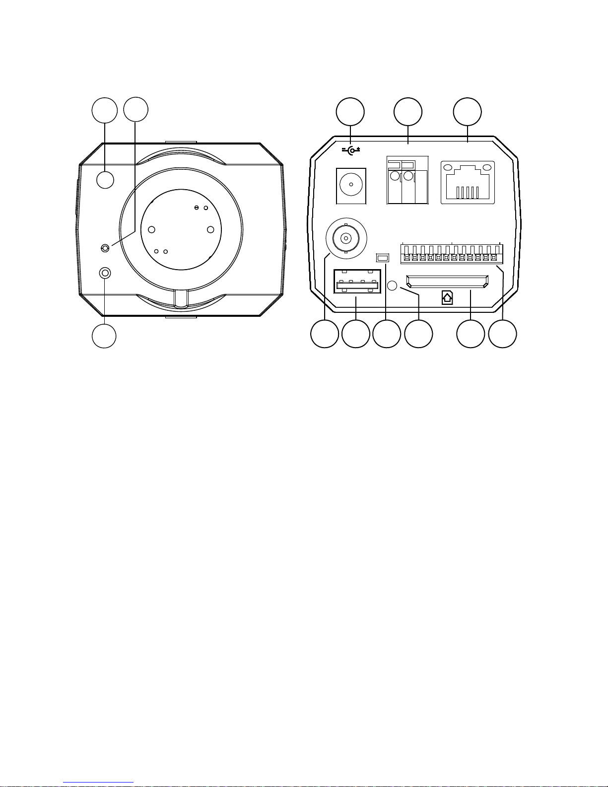
2.1 Front Panel and Rear Panel
-- Front Panel -- -- Rear Panel --
1
3
2
SD / SDHC
ETHERNET
(PoE)
AC 24V
DC 12V
VIDEO
USB
112
RESET
6
!
456
7
8
9
10 11 12
1. Light Sensor: Registers the quality of light in the camera’s environment, and controls the iris
shuttle to provide better information concerning the light.
2. MICROPHONE: The IP Camera has an additional audio function. The device has a
microphone built into its front panel which records sound.
3. POWER indicator: Indicates the power status of the unit.
4. Plug Inlet: A DC 12V inlet that connects to an external power supply.
5. Plug Inlet: An AC 24V inlet that connects to an external power supply.
6. ETHERNET 10/100 Connector: This is a standard RJ-45 connector for 10/100 Mbps
Ethernet networks. PoE (Power over Ethernet) function:
Provides pow er to the device via the
same cable as used for the network connection.
7. VIDEO OUT Connector: The connector provides the unit’s composite video signals to a
monitor.
8. USB port: The user can use a USB device cable to connect the IP camera to the USB port on
the PC.
9. RESET: Recover to factory default.
10. LED indicator: The green light indicates the unit is activating and the SD card cannot be
removed.
11. SD C ARD slot: This is used for updating system software and archiving / accessing critical
images.
12. ALARM I/O: This is a 12-PIN connector including the ALARM IN/OUT, ALARM RESET,
GROUND and AUDIO items for connecting with external devices.
9
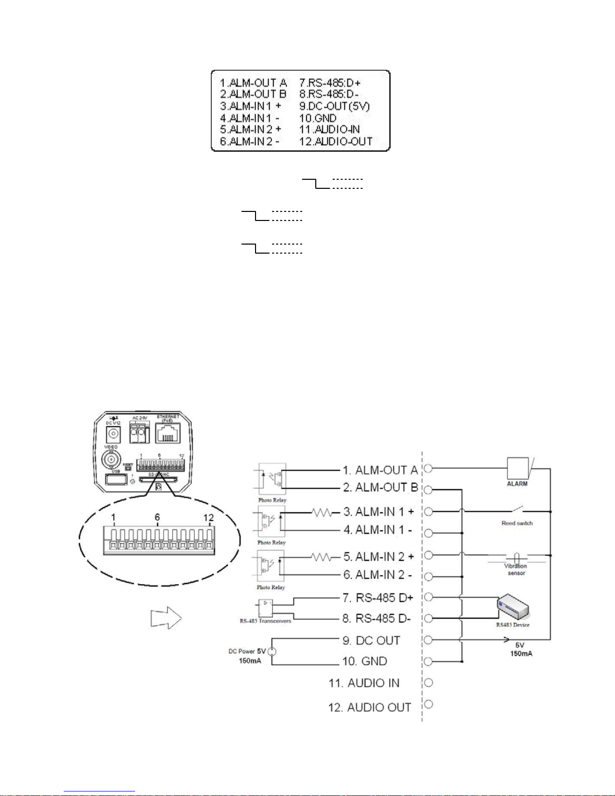
2.2 ALARM I/O
1 & 2. ALARM OUT (OUTPUT): This is an alarm output trigger. Connect this to external
devices such as buzzers or lights. ( )
3 & 4. ALARM IN 1 (INPUT): This is an alarm input that can be programmed in the menu
system to active low. ( )
5 & 6. ALARM IN 2 (INPUT): This is an alarm input that can be programmed in the menu
system to active low. ( )
7. RS-485 D+
8. RS-485 D-
9. DC OUT (5V)
10. GND: Ground contact.
11. AUDIO IN
12. AUDIO OUT: This provides the unit’s audio signal to a speaker.
Alarm wiring diagram:
5V, 20mA
0V(Active)
5V, 20mA
0V(Active)
5V, 20mA
0V(Active)
10
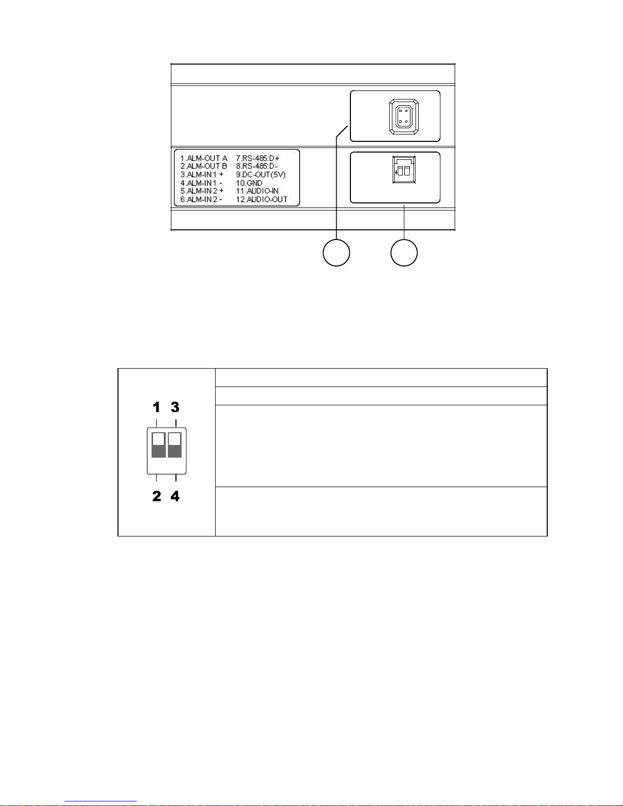
2.3 Flank Panel
IRIS
1. AES
2. DC IRIS
3. DHCP
4. STATIC IP
1
2
3
4
1.ALM-OUT A
2.ALM-OUT B
3.ALM-IN +
4.ALM-IN -
5.ALM-RST +
6.ALM-RST -
7.RS-485:D +
8.RS-485:D -
9.DC-OUT(5V)
10.GND
11.AUDIO-IN
12.AUDIO-OUT
1
2
1. IRIS: Auto iris connector.
This camera works with a DC drive auto iris lens. Please refer to the pin assignment
marked on the camera when connecting the auto iris lens
2. DIP Switch:
1. AES: Auto electric shutter.
2. DC IRIS: Use an auto iris (DC drive)
3.DHCP: Turn On / Turn Off to use the DHCP protocol. If the switch
points upwards, the device can change the setup of
network function (enable/disable) via the network.
(*In the default factory configuration, this DIP Switch is in
the Up position.)
4. STATIC IP: If the switch points down, the device can’t obtain an IP
address from the DHCP server. This option is needed
to configure the network communication settings.
11
2.4 The USB function
By connecting the IP camera with a PC via the USB connector, the IP camera can provide two
different functions.
1. Insert an SD card: As a card reader.
Insert an SD card into the IP camera, then connect to the PC. Y ou might transfer files between
the SD card and the PC. Once you've connected your IP camera to your computer, the
Windows system will detect the connection and ask you what you want to do with your SD
card.
In other words, if the user connects the IP camera with an SD card and the PC via the USB
connector, the IP camera can be used as a normal card reader.
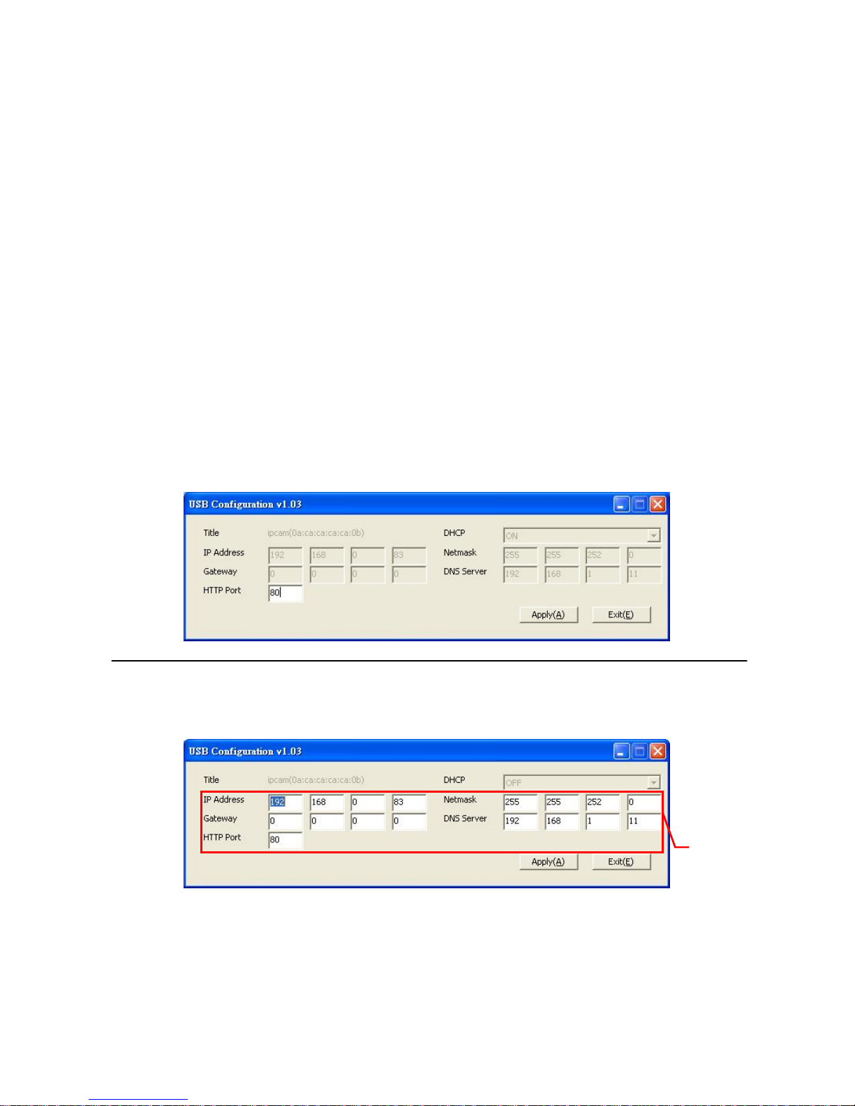
2. Remove an SD card: As a configuring tool.
Before using the USB configuration setting page, please remember to remove the SD card or
your PC will read the SD card and won’t show this window.
DHCP ON
DHCP OFF
(default)
NOTE: After changing the settings, please click the “Apply” button. All of the options
will be effective after removing the USB connector.
NOTE: After the IP address has been changed, please unplug the network cable, then
plug it once again to make sure the network connection is in normal mode.
Network
Setting
12
3. INSTALLATION
Please follow the instructions and the diagram below to set up the system.
NOTE: The IP Camera is linked by its Video Out connec tion via a BNC connector to a
monitor's Video In connection. If this connection is there, you can see some
information on the monitor screen, such as the IP Camera factory default Static IP
address (192.168.1.168). But the IP Camera Static IP address can only appear if
there is a connection between the IP Camera and another device. If there is no
such connection, the IP Camera factory defaul t Static IP address will not app ear
on the monitor screen.
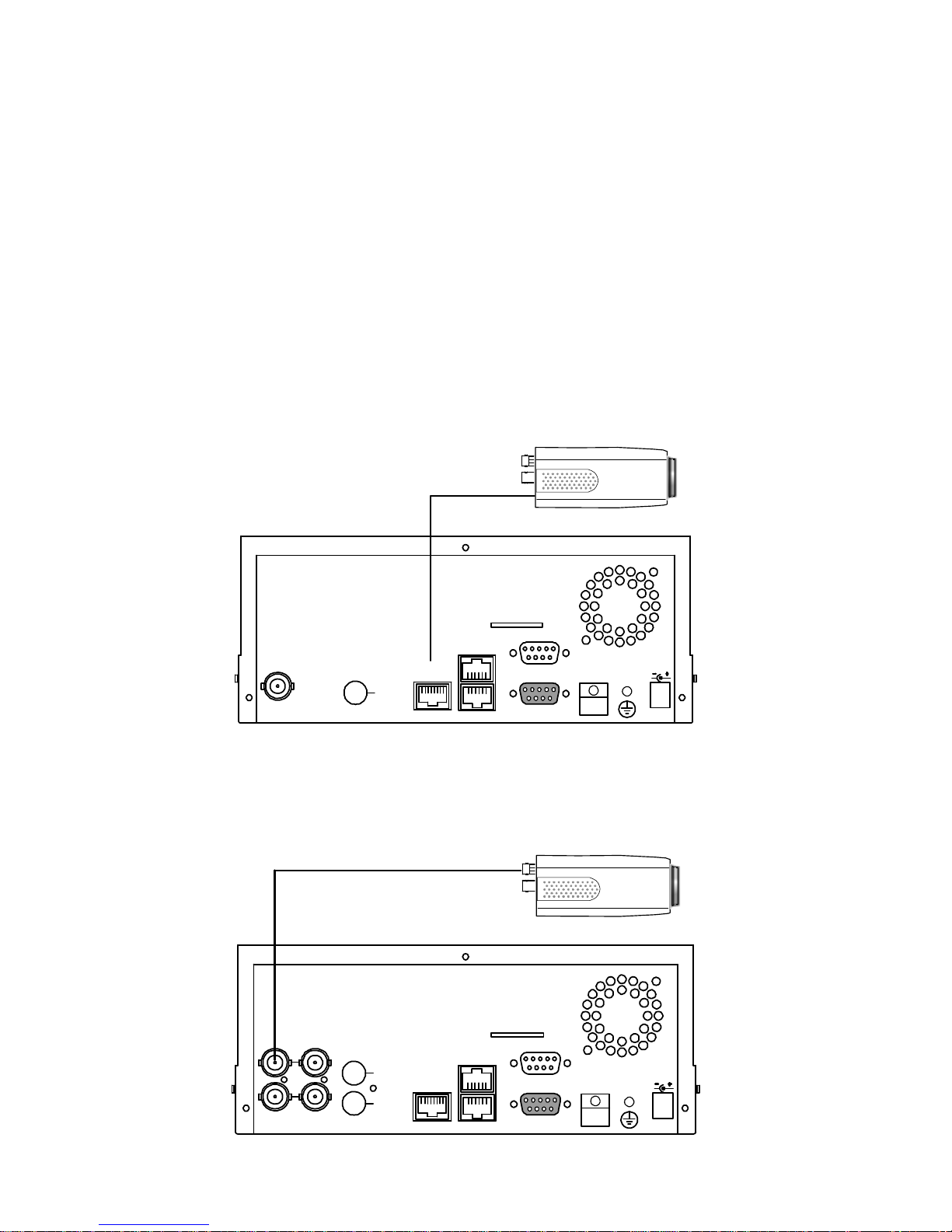
3.1 CONNECTING WITH AN NVR
Use a straight LAN cable to connect directly to an NVR.
SD Card
RS-232
ALARM
DC12V
AUDIOVIDEO
OUT
OUT
I/O
RS-485
ETHERNET
10/100
LAN CAMERA
CONNECT TO ETHERNET
RJ45 CONNECTOR
CONNECT TO NVR
ETHERNET PORT
3.2 CONNECTING WITH A DVR
SD Card
RS-232
ALARM
DC12V
AUDIO
IN
IN
OUT
OUT
VIDEO
TO
MONITOR
TO
MUX'S VCR IN
FROM MUX
MAIN MONITOR
I/O
RS-485
ETHERNET
10/100
LAN CAMERA
CONNECT TO VIDEO OUT
BNC CONNECTOR
CONNECT TO DVR
VIDEO IN
13
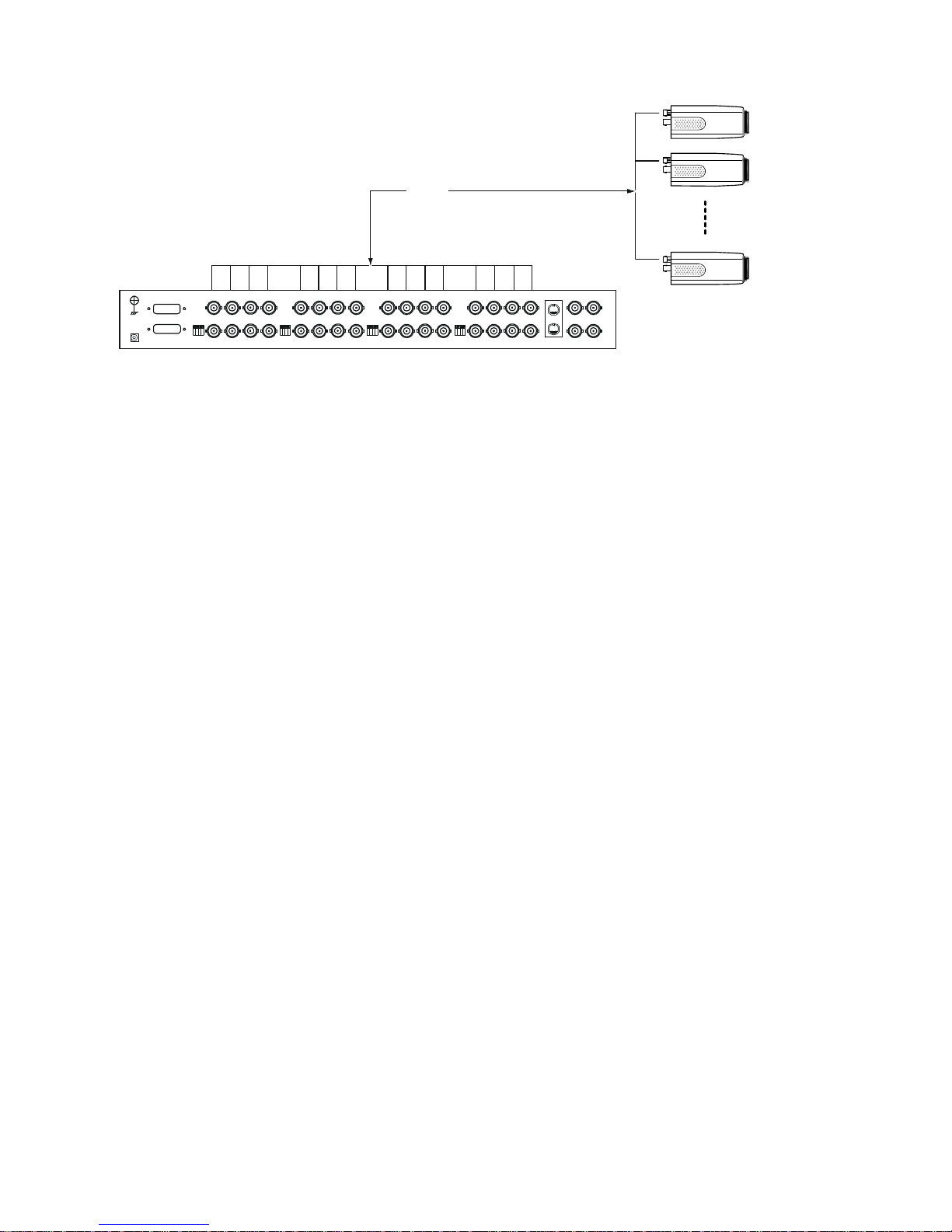
3.3 CONNECTING WITH A MULTIPLEXER
LAN CAMERA 1
LAN CAMERA 2
LAN CAMERA 16
TO LAN CAMERA VIDEO OUT BNC CONNECTOR
3.4 UPDATING SYSTEM SOFTWARE
If the system software of the IP Camera needs to be upgraded, please take the following steps to
safely process it.
Important: Before carrying out the following procedures, please ensure the SD card is
working and the file of the system firmware is intact
1. Create a directory named UPGRADE (upper-case or lower-case letters are no difference) in the
SD card if it does not exist.
2. Copy the file of UPDATE.BIN to the UPGRADE -directory.
3. If the IP Camera is running, please power it off first.
4. Insert the SD CARD into the IP Camera.
5. Remove the Ethernet cable from the RJ-45 port and then power on the IP Camera.
6. In 5 to 10 seconds, a message reading "UPDATE PROCESSING" will show up on the screen on
a blue background; if not, please check out steps 1 to 6 carefully or else inform your technical
support while ignoring the following steps.
7. DO NOT power off the IP Camera while this update process is running until the message
"UPDATE OK RESET PLEASE" appears on the screen; it might take 15 to 30 seconds to
appear.
8. If the message "UPDATE NG RESET PLEASE" appears rather than "UPDATE OK RESET
PLEASE", please write down the error messages shown on the screen and inform your
technical support, while ignoring the following steps.

14
9. Power off the IP Camera when this update process is finished, then remove the SD card from
the IP Camera.
10. Reconnect the Ethernet cable to the RJ-45 port if necessary.
11. Power ON the IP Camera and it will work normally if the entire update procedure goes correctly.
12. Verify the version of the system software.
WARNING:
1. Steps 1 to 2 have to be done on a PC.
2. Make sure the file of UPDATE.BIN is a correct one in step 2, or the IP Camera will not
work normally after being updated.
3. If the power of the IP Camera is suddenly lost in step 7, please remove the SD card first
and turn on the IP Camera next to test its operation. If the IP Camera remains working
normally, please go back to step 3; otherwise, please inform your technical support.
4. In step 9, if the SD card is not removed and the IP Camera does not get online as well,
the updating process must be repeated again after rebooting the IP Camera.
5. Make sure that the SD card is inserted in a correct position in step 4, or the IP Camera
will suffer permanent physical damage.
6. If the message "CSUM ERROR" appears in step 7, it implies a problem in the file of
UPDATE.BIN.
7. Don’t interrupt the process while the unit is updating itself; proceed with an SD card
not including any system software of the unit, or else the unit will crash.

15
4. Network Configuration
4.1 Cable Connections
Please follow the instructions below to connect your IP camera to a computer or a network and to
choose a proper RJ-45 cable configuration for connections.
Physical specifications of the RJ-45 cable for Ethernet
Wire Type Cat. 5
Connector Type RJ-45
Max. Cable Length 100 m
Hub Wiring Configuration Straight Through
PC Wiring Configuration Straight Through
4.2 Configure Your IP Camera Network Settings
Upon connecting with the network hardware, you need to activate the network function and
configure the proper network settings of the IP camera.
4.2.1 Enable DHCP Function
This function can onl
y work if the LAN, which the unit is connected to, has a DHCP server. If the
DHCP server is working, please move the dip switch points up to 3 on the flank p anel; now the IP
camera will obtain an IP address automatically from the DHCP server. In this instance, please
skip section 4.2.2 (Set IP address) and follow section 4.3 (TCP/IP Communication Software).
4.2.2 Set IP Address
Y
ou need to set an IP address for the unit if the LAN unit isn’t connected to a DHCP server.
Otherwise, please follow the instructions given below:
Set the IP, MASK and GATEWAY. The following is a sample setting.
IP: 192.168.1.X
MASK: 255.255.255.0
GATEWAY: 0.0.0.0

16
NOTE: When only one unit of the IP camera is connected to a computer or LAN, you can
freely assign an IP address for the IP camera. For example, there is a range of IP
camera IP addresses from 192.168.1.1 to 192.168.1.255. You can pick one for use
from the range of the IP. It’s not necessary to set MASK and GATEWAY; leave the
settings as default.
When an IP camera is connected to a WAN, you must acquire a unique,
permanent IP address and correctly configure the MASK and GATEWAY settings
according to your network architecture. If you have any questions regarding
those settings, please consult a qualified MIS professional or your ISP.
NOTE: When connecting to a network, each connected IP camera must be assigne d a
unique IP, which must be in the same class type as your network address. IP
addresses are written as four sets of numbers separated by periods; for example,
192.168.1.1 Therefore, if the connected network is identified as Class C, for
example, the first three sets of numbers of the IP camera IP address must be t he
same as in the network address. If the connected network is identified as Class B,
the first two sets of numbers of the IP camera IP address must be the same as in
the network address. If you have an y question s regarding these set tings, please
consult a qualified MIS professional or your ISP.
17
4.3 TCP/IP Communication Software
Follow the procedure below to install the TCP/IP communication program in your computer.
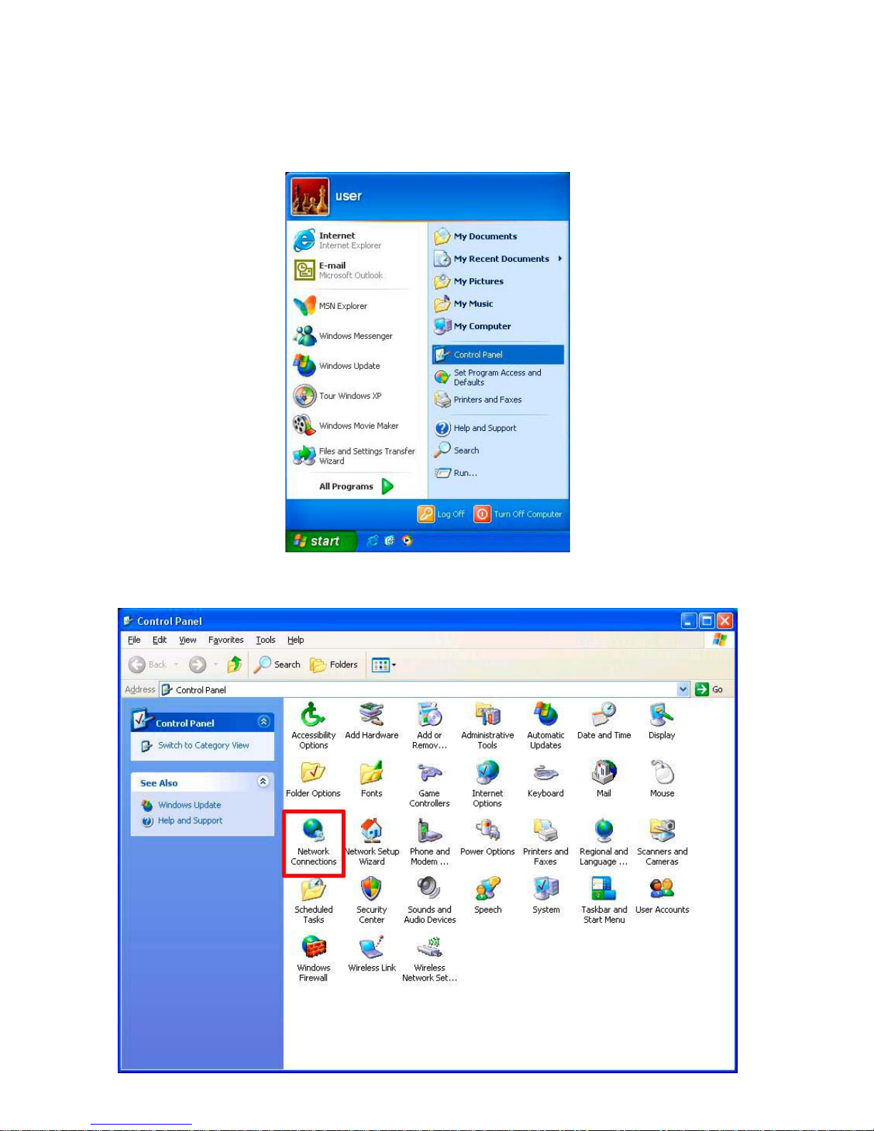
1. Click Start, and then click Control Panel.
2. Double click the Network Connections icon to enter the windows.
18
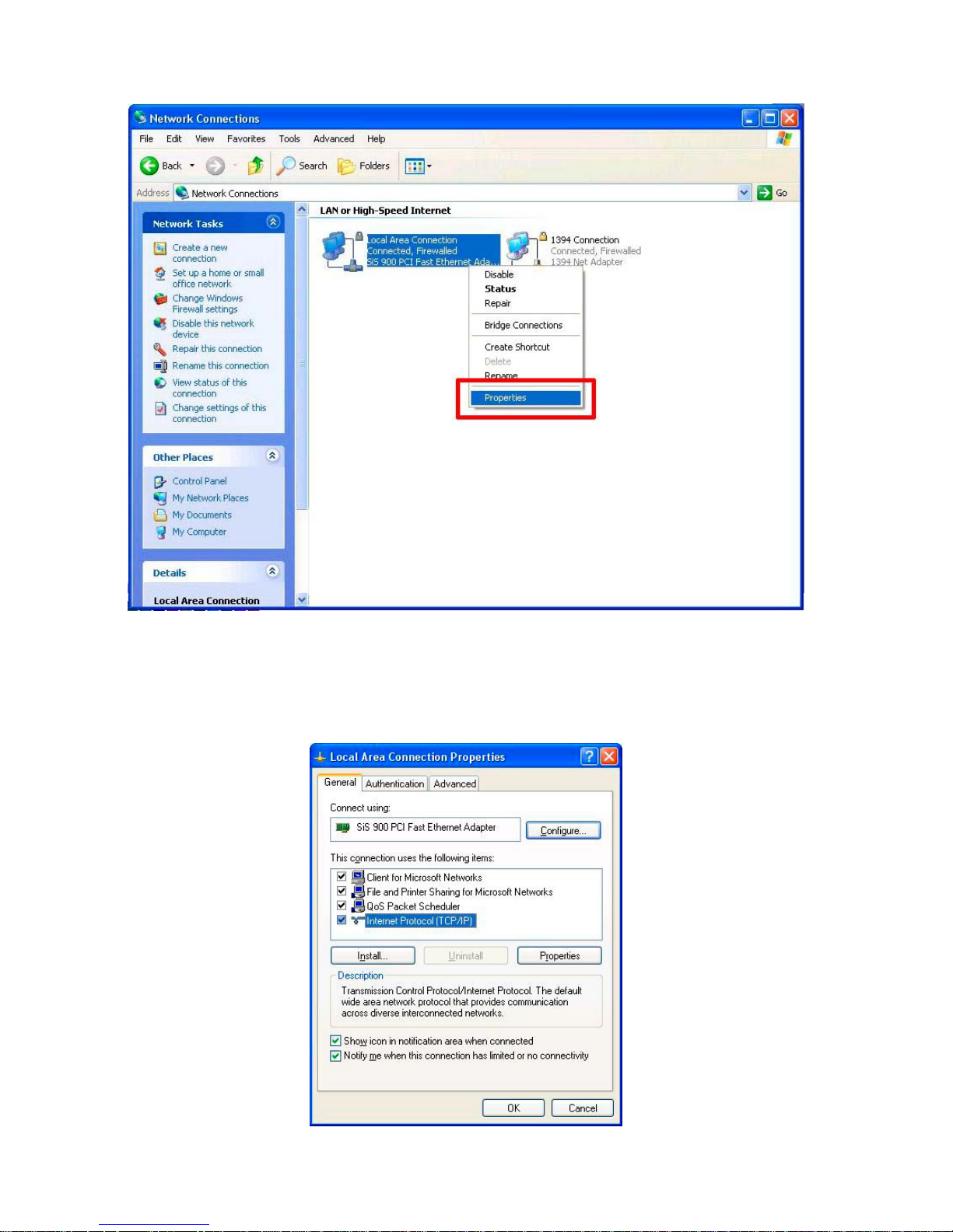
3. Right-click your network connection, and then click Properties.
4. On the General tab, check if the Internet Protocol (TCP/IP) is included in the list. If the
TCP/IP is included, please process section 4.5. If it is not included, please follow section 4.4
to install the TCP/IP.
19
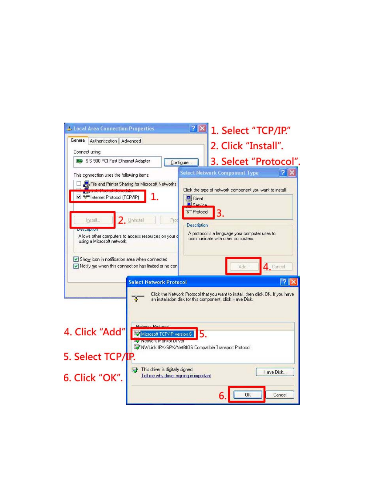
4.4 TCP/IP Installation
On the General tab of the Connection Properties, under “This connection uses the following
items”, click Internet Protocol (TCP/IP). Then click Install. Select Protocol from the network
component type then click Add. Select Microsoft TCP/IP from the network protocol then click
OK.
Click Close to return to the Network Connections window.
20
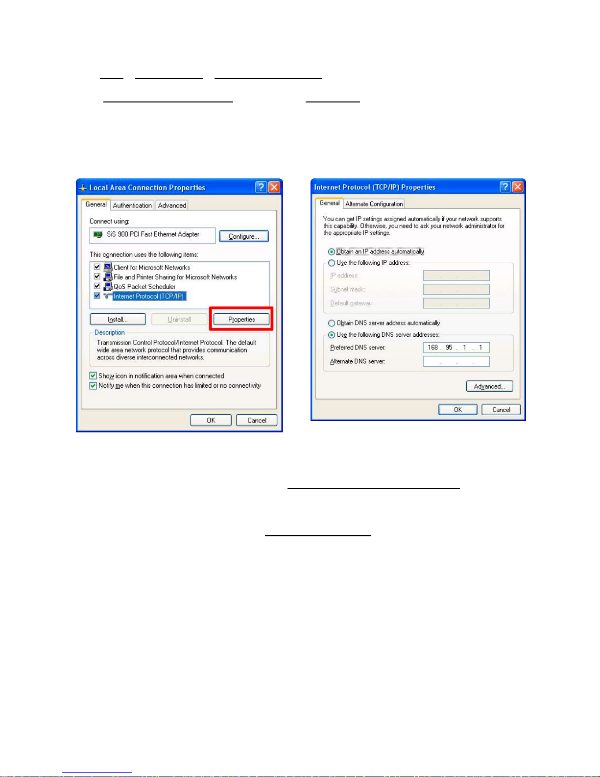
4.5 TCP/IP configuration setting
Click Start > Control Panel > Network Connections.
Select Internet Protocol (TCP/IP)
, and then click Properties.
Before processing the IP camera installation in a WAN, please make sure the Internet
connection works properly. If not, please contact your ISP provider.
If you are using a DHCP server, please select Obtain an IP address automatically
. Any
assigned IP address for the connected IP cameras must be in the same class type as the server .
If there is no DHCP server, please select specify an IP address
enter the IP address, subnet
mask and default gateway of your choosing of your PC. This IP address must be different from
other network IP devices but in the same class type.
NOTE: The IP address of an IP camera in a network must be unique to itself as opposed
to those of the other chosen PCs, but in the same class type.
21
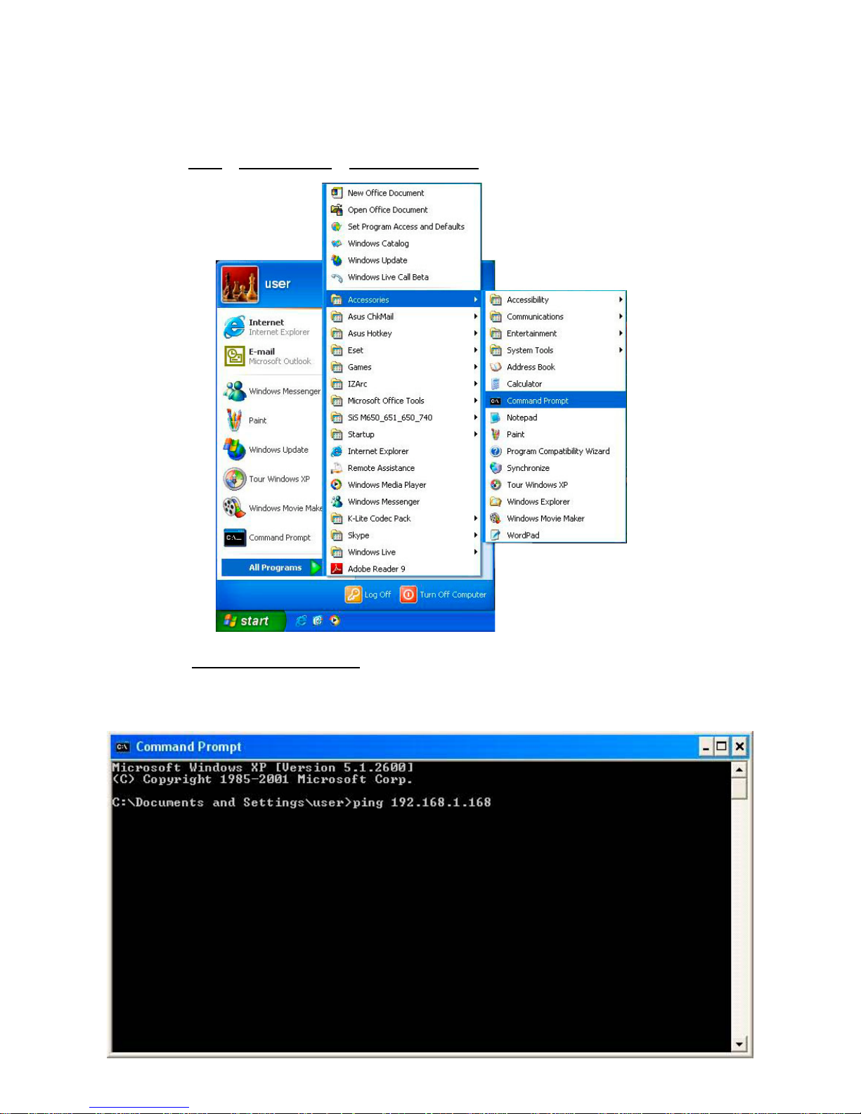
4.6 Connection Testing
With the previous settings, follow the instructions below to ensure whether you have established
the connection successfully.
1. Click Start
> All Programs > Command Prompt.
2. Enter ping XXX.XXX.XXX.XXX
(the camera’s IP address), then enter. (See the sample
screen below).
** This is the IP address for an IP camera that is assigned for the connected IP camera.
22
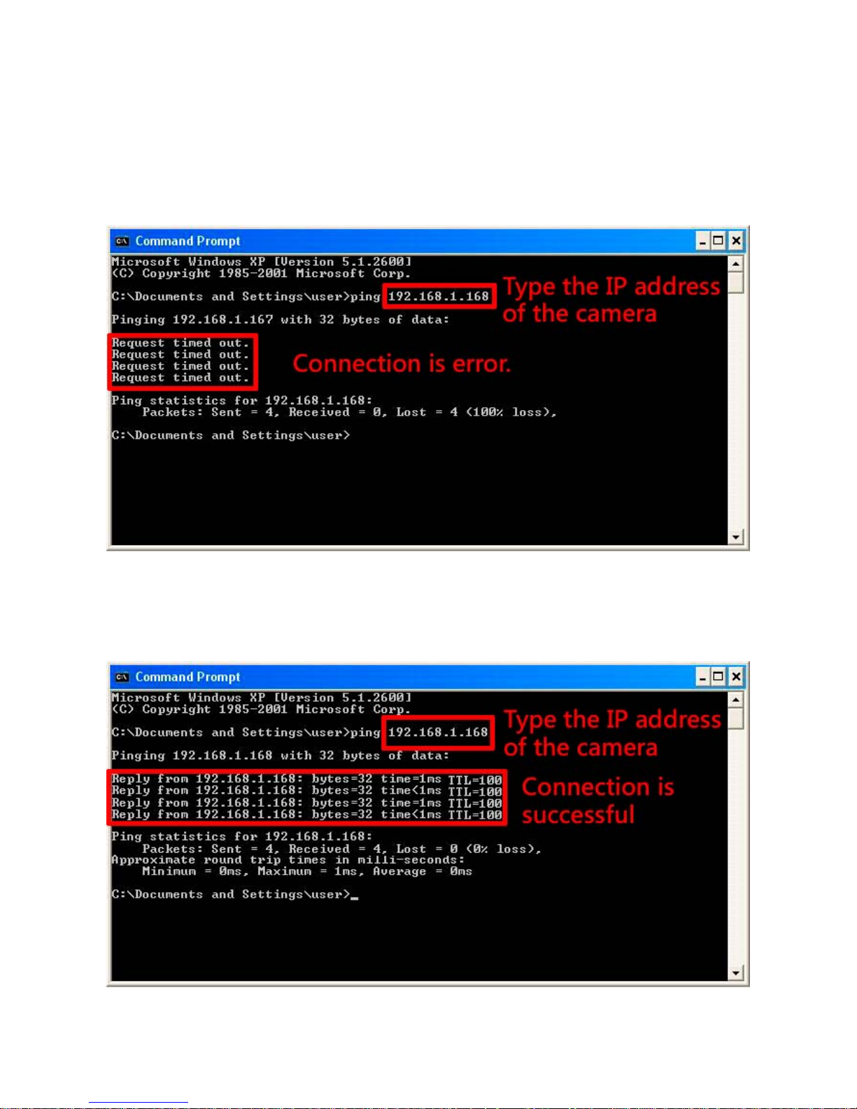
If you receive a response as in the sample screen below, the connection hasn’t been
successfully established. Please re-check all the hardware and software installations by
repeating sections 4.4 and 4.5. If you still can’t establish the connection after rechecking, please
contact your dealer.
If you receive a response as in the sample screen below, you have successfully made the
connection.
23
5. Operating Instructions for Image Software and Network
Two choices of software are available for linking with the IP camera: (1) the Microsoft Internet
Explorer; and (2) the IP camera viewer software, a network browser in a PC which provides the
functions of monitoring remote zones or watching recorded data through the TCP/IP protocol.
The details are listed as follows.
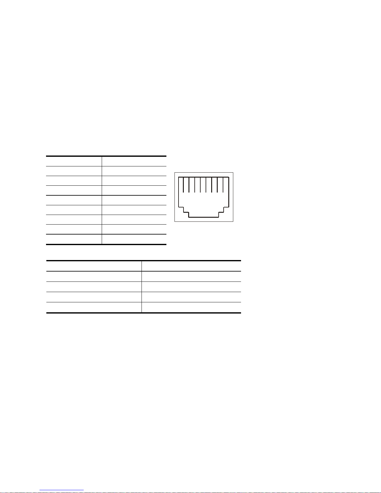
RJ-45 PIN configuration for Ethernet
PIN NO. PIN Assignment
1. TX +
2. TX -
3. RX +
4. Not Connected
5. Not Connected
6. RX -
7. Not Connected
8. Not Connected
Physical specification for Ethernet
Wire type Cat. 5
Connector type RJ-45
Max. cable length 100 m
Hub wiring configuration Straight Through or Cross Over
PC wiring configuration Straight Through or Cross Over
1 2 3 4 5 6 7 8
RJ-45 socket
24
5.1 Microsoft Internet Explorer
5.1.1 Connecting the IP
camera
1. Start up the Microsoft Internet Explorer, and then follow the steps below to connect the IP
camera.
2. Click on the URL block at the top of the window.
3. Enter the URL address of the IP camera into the URL block and press the “Enter” button to
enter the home page.
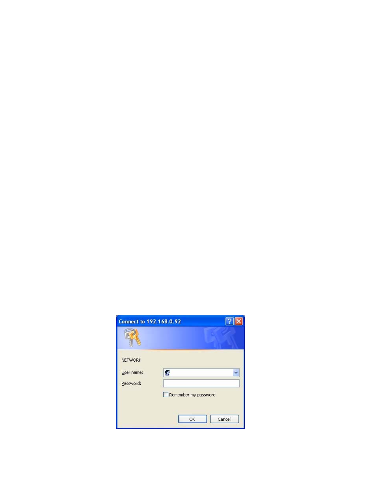
4. Enter the "User Name" and "Password" in the appropriate spaces.
5. Click on the “OK” button to set your entries, and automatically exit the page.
NOTE: The default "User Name" and "Pa ssword" are admin and 9999, respectively.
NOTE: The page headlined "En ter Network Passw ord” is shown below. Please enter the
user name and password of the IP camera when you see it. If either the user name
or the password is incorrect, please check the input data and rectify it as
necessary.
NOTE: Once authorized successfully, the login page will not appear again until you close
the window and reconnect it.
NOTE: The initial sequence of proceeding is to type in your IP address and click the
"Enter" button to access the home page. If and when you revise or change data in
the "SYSTEM USERS" page, the sequence will alter to initially show the "Enter
Network Password" page.
25
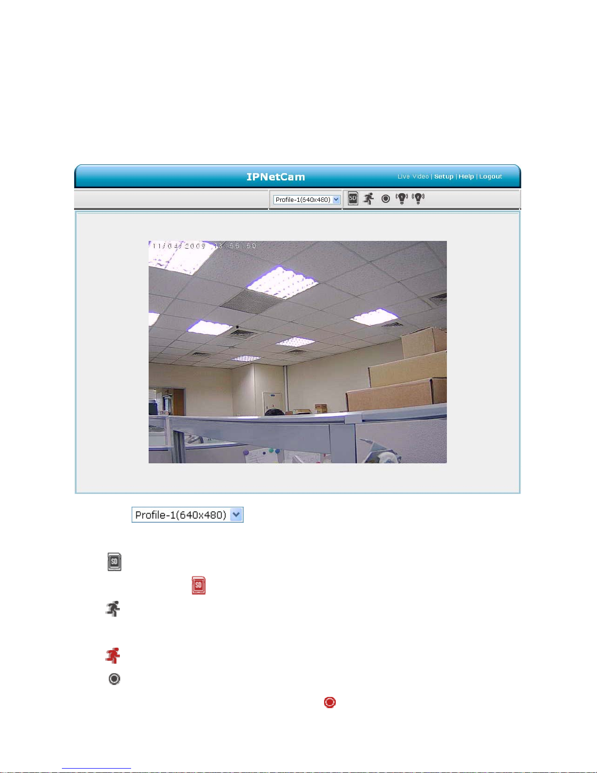
5.1.2 Live Video
The Live Video from the IP camera is displayed on the home page when your PC is online with
the IP camera. There are also additional settings provided on the home page. The AJAX (default)
and the ActiveX viewer types display different display formats on their home page.
The AJAX viewer type: Non-IE browsers support (for the JPEG mode only).
Click
to change the pairs of resolution and quality which you
already arranged in the “Audio and Video” setting page (for the JPEG mode).
SD card icon: Check if the SD card is inserted or not. When a SD card is inserted, t he
icon becomes red
.
Motion-on icon: When there is a detection of motion, the icon will appear in the right
upper corner to warn the user.
When the motion detection is triggered, the icon will blink red
.
Status Recording on icon: The icon will appear on the upper right corner. When the
recording is triggered, the icon will become red
and record the images into the inserted
SD card.

26
Alarm on-icon: When there is a detection of external devices such as a sensor, The
icon will appear on the upper right corner warn the user. When an alarm is triggered, the
icon will blink red
.
Alarm on-icon: When there is a detection of external devices such as a sensor, the icon
will appear on the upper right corner warn the user. When an alarm is triggered, the icon will
blink red
.
27
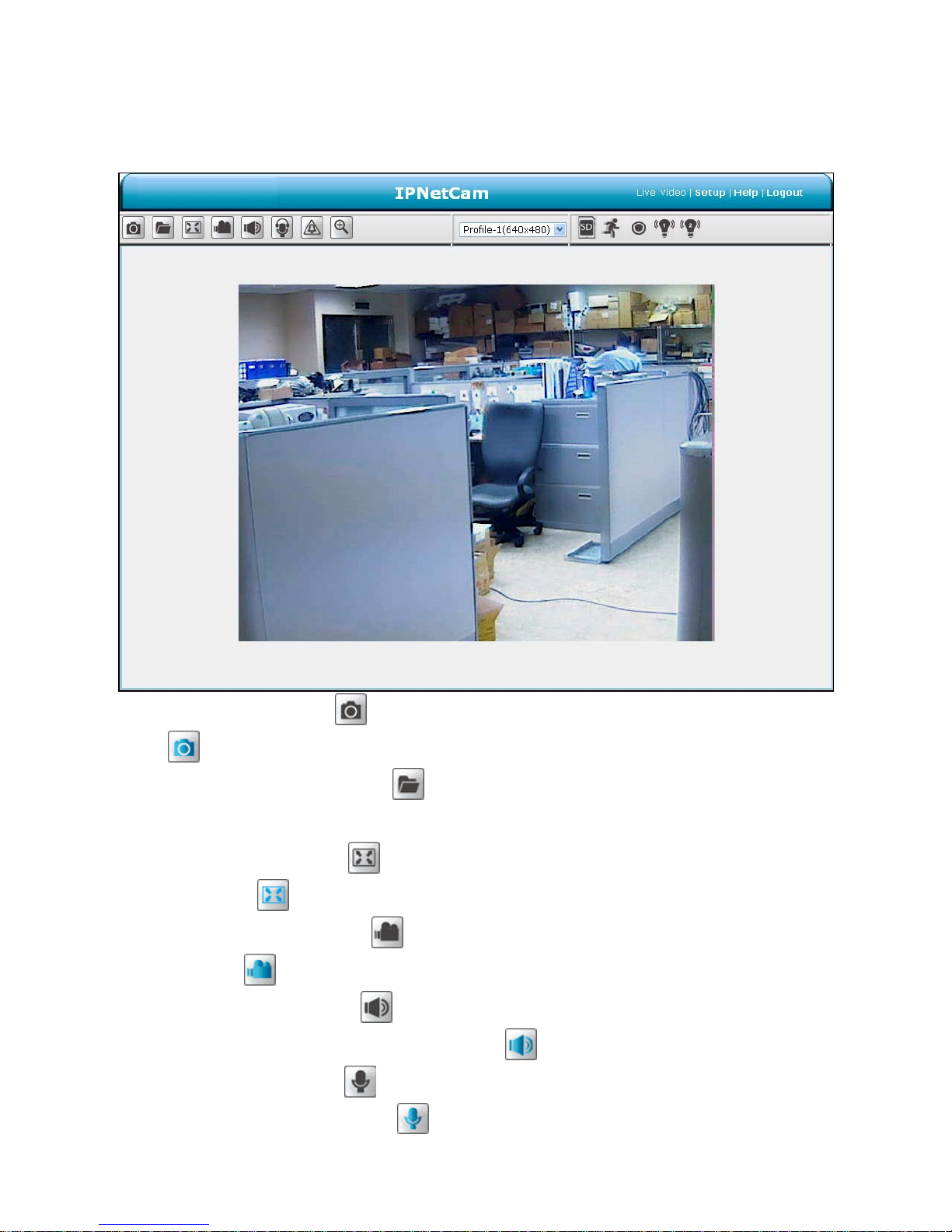
The ActiveX viewer type:
You can select from the available thumbnails for your option of taking a Snapshot, setting the
Storage Folder, selecting the Full Screen mode, Recording, Listen, Talk and Zoom.
Snapshot: Click on the button to take a snapshot. The icon w ill change to a blue color
while working effectively.
Set Storage Path: Click on the
button to set a storage folder for saving the snapshot
and the video clips.
Full Screen: Click on the
button to enter the full screen mode. The icon will change to
a blue color
while working effectively.
Record switch: Click on the
button to record a video clip. The icon will change to a
blue color
while working effectively.
Audio switch: Click on the
button to start/stop the audio-in function (listen/stop
listening). The icon will change to a blue color
while working effectively.
Talk switch: Click on the
button to start/stop audio out function (talk/stop talking). The
icon will change to a blue color
while working effectively.
28
Digital output: Click on the button to start/stop digital output. The icon will change to a
blue color
while working effectively.
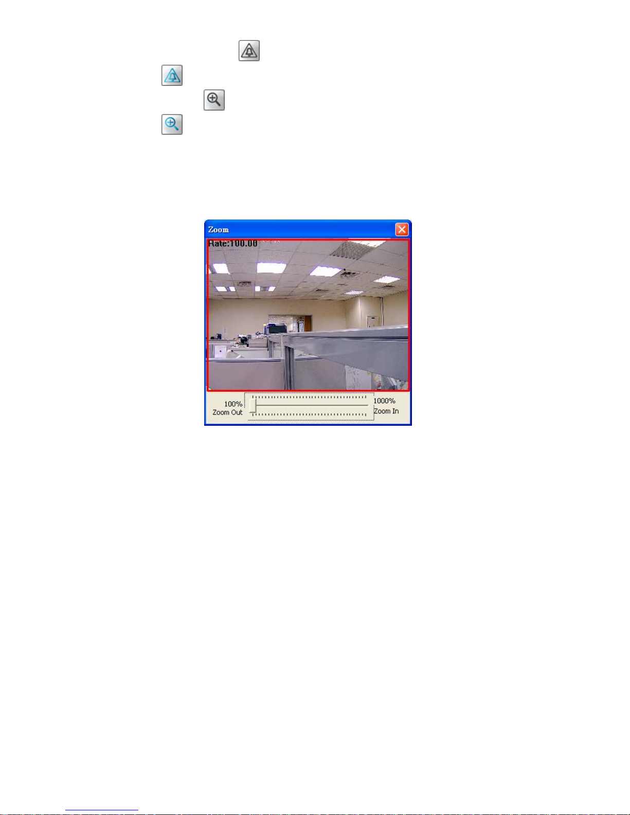
Zoom: Click on the
button to bring a popup “Zoom” window . The icon will change to a
blue color
while working effectively. Move the scrollbar "square" right or left to zoom
in or zoom out the Live View, and the red “Active Frame” will be narrowed down or
enlarged. You can drag the “Active Frame” to the desired position to see the detail of the
live image.
Live Video: Click to go back to the device’s homepage.
Setup: Click to proceed to the advanced settings.
Logout: Click to close the window.
 Loading...