

Page 1

Solid-State Memory Camcorder
FX6
ILME-FX6V/ILME-FX6VK
ILME-FX6T/ILME-FX6TK
5-024-458-
14
(1)
GB
Software Version 2.0
E-mount
Operating Instructions
© 2020 Sony Corporation
Page 2

2
Table of Contents
1. Overview
System Configuration........................................3
Location and Function of Parts
Using the Touch Panel
Screen Display
.................................................. 11
..........................4
.................................... 10
2. Preparation
Power Supply ...................................................17
Attaching Devices
Configuring Basic Camcorder Operation
Using Memory Cards
............................................19
....................................... 26
3. Shooting
Basic Operation Procedure ..............................34
Adjusting the Zoom
Adjusting the Focus
Adjusting the Brightness
Adjusting for Natural Colors (White
Balance)
Setting the Audio to Record
Useful Functions
Proxy Recording
Shooting with the Desired Look......................55
Shooting with Look Adjustment in
Post-Production
Recording RAW Video
........................................ 36
........................................ 37
................................ 43
.................................................... 46
............................ 47
.............................................49
.............................................. 54
....................................... 57
..................................... 58
4. Network Functions
Connecting to Other Devices via LAN ..............59
Connecting to the Internet
Uploading Files
............................................... 64
.............................. 62
......... 24
5. Thumbnail Screen
Thumbnail Screen ...........................................66
Playing Clips
Clip Operations
.................................................... 67
...............................................68
6. Menu Display and Settings
Full Menu Configuration and Hierarchy ..........69
Full Menu Operations
User Menu
Edit User Menu
Shooting Menu
Project Menu
Paint/Look Menu
TC/Media Menu
Monitoring Menu
Audio Menu
Thumbnail Menu.............................................96
Technical Menu
Network Menu
Maintenance Menu
Shooting Menu Settings and Default
Image Quality Settings Saved for Each Shooting
Saving and Loading Configuration Data
....................................................... 73
....................................................94
Values
......................................................105
Mode
...................................................... 109
.......................................71
................................................ 74
............................................... 75
...................................................80
............................................ 87
..............................................89
.............................................91
............................................... 97
.............................................. 100
....................................... 104
7. External Device Connection
Connecting External Monitors and Recording
Devices
.....................................................111
Synchronizing Timecodes
Managing/Editing Clips using a Computer
.............................. 112
........ 110
.... 113
8. Appendix
Usage Precautions .........................................114
Output Formats and Limitations
Troubleshooting.............................................117
Error/Warning Messages
Items Saved in Files
Block Diagrams
Updating E-mount Lens Software
Licenses..........................................................133
Specifications
....................................... 121
..............................................129
.................................................136
.................... 115
............................... 119
..................132
Page 3
1. Overview
1. Overview
3
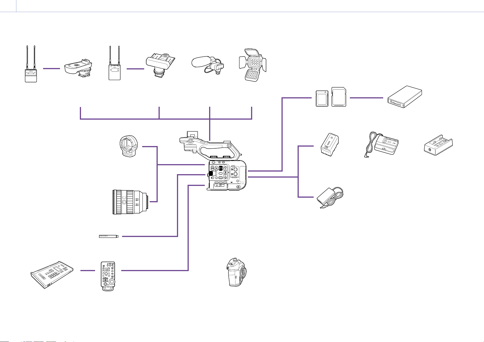
System Configuration
UWP-D21
UWP-D22
UWP-D26
Wireless
Microphone
Package
SMAD-P5
Multi-Interface
Shoe Adaptor
URX-P03D
Wireless
Microphone
Receiver
SMAD-P3D
Multi-Interface
Shoe Adaptor
XLR-K2M
XLR-K3M
XLR Adaptor Kit
HVL-LBPC
Video Light
CFexpress Type A
memory cards
SDXC
memory cards
CFexpress Type A card reader/
SD card reader
MCX-500
Multi Camera Live
Producer
LA-EA3
LA-EA4
A-mount Adaptor
E-mount lens
ECM-VG1
ECM-MS2
Microphone
RM-30BP
Remote Control Unit
ILME-FX6V/ILME-FX6VK
ILME-FX6T/ILME-FX6TK
Grip remote control
(supplied)
BP-U35, BP-U60,
BP-U60T, BP-U70,
BP-U90, BP-U100
Battery Pack
AC adaptor
(supplied)
BC-U1A, BC-U2A
Battery Charger
BC-CU1
Battery Charger
(supplied)
Page 4
1. Overview
11
2
4
5
6
8
9
12
13
14
3
16
15
10
4
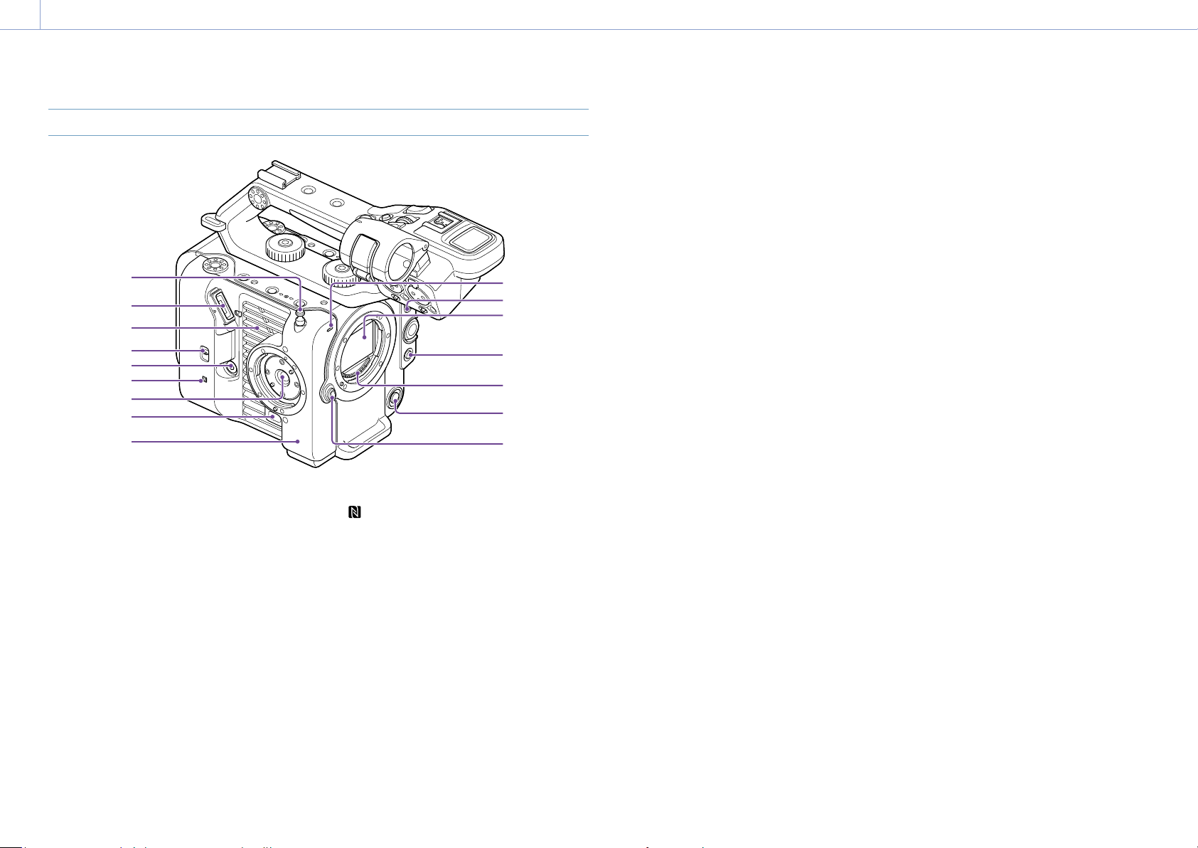
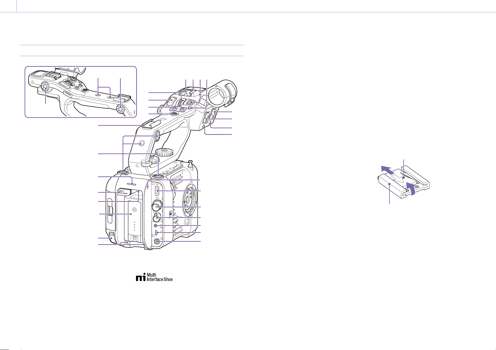
Location and Function of Parts
Left Side and Front Side
1
10. Recording/tally lamp (front) (page 34)
Flashes when the remaining capacity on the
recording media or battery is low.
11. FOCUS switch (page 37)
12. Image sensor
13. PUSH AUTO FOCUS button (page 40)
14. Lens signal contacts
[Note]
Do not touch directly with your hands.
15. WB SET (white balance set) button
(page 46)
16. Lens release button (page 22)
7
1. Tape measure hook
The tape measure hook is on the same plane
as the image sensor. To measure the distance
between the camcorder and the subject
accurately, use this hook as a reference point.
You can attach the end of a tape measure to
the hook to measure the distance from the
subject.
2. Viewfinder connector (page 19)
3. Air vent
[Note]
Do not cover the air vent.
4. TC IN/OUT select switch (page 34,
112)
5. Grip remote control connector
(page 20)
6. (N-Mark) (page 59)
Touch a smartphone equipped with the
NFC function against the unit to establish a
wireless connection.
Some smartphones that support wireless
pay systems may not support NFC. For
details, refer to the operation manual for the
smartphone.
NFC (Near Field Communication) is an
international communications protocol for
wireless communication between objects in
close proximity.
7. Grip remote control attachment
(page 20)
8. Grip remote control release button
(page 20)
9. Wi-Fi antenna
Page 5
1. Overview: Location and Function of Parts
1816
5
Right Side (Front/Top/Bottom)
1
2
3
4
5
6
7
8
9
10
11
12
13
9. Multi-function dial (page 49)
Press when viewing the image in the
viewfinder to display and operate the direct
menu.
Turn the dial when a menu is displayed in the
viewfinder to move the cursor up/down to
select menu items or settings. Press to apply
the selected item.
When the menu is not being displayed, the
dial can also function as an assignable dial.
10. IRIS function button (page 43)
11. CANCEL/BACK button (page 67)
Right side (rear) (page 6)
19171514
20
12. THUMBNAIL button (page 66)
13. MENU button (page 13, 71)
Press the MENU button to display the status
screen. Press and hold the MENU button
to display the full menu screen. Press the
button during status screen or full menu
screen display to return to the previous screen
display.
14. ISO/GAIN function button (page 43)
15. ISO/GAIN (gain select) switch (page 43)
16. WHT BAL (white balance) function button
(page 46)
17. WHT BAL (white balance memory select)
switch (page 46)
18. SHUTTER function button (page 44)
19. Headphone jack (page 34)
20. POWER switch (page 34)
1. Clip Flag button (page 53, 68)
2. HOLD switch (page 97)
3. Record START/STOP button (page 34)
Press the record START/STOP button to start
recording. The LED is lit red while recording.
4. ND VARIABLE dial (page 44)
5. ND PRESET/VARIABLE switch (page 44)
6. ND FILTER POSITION up/down buttons
(page 44)
7. ND CLEAR indicator (page 44)
8. ND VARIABLE AUTO button (page 44)
Press the ND VARIABLE AUTO button to start
auto density adjustment of the ND filter. The
LED is lit green when turned on.
Page 6
1. Overview: Location and Function of Parts
8
7
6
5
4
12
14
6
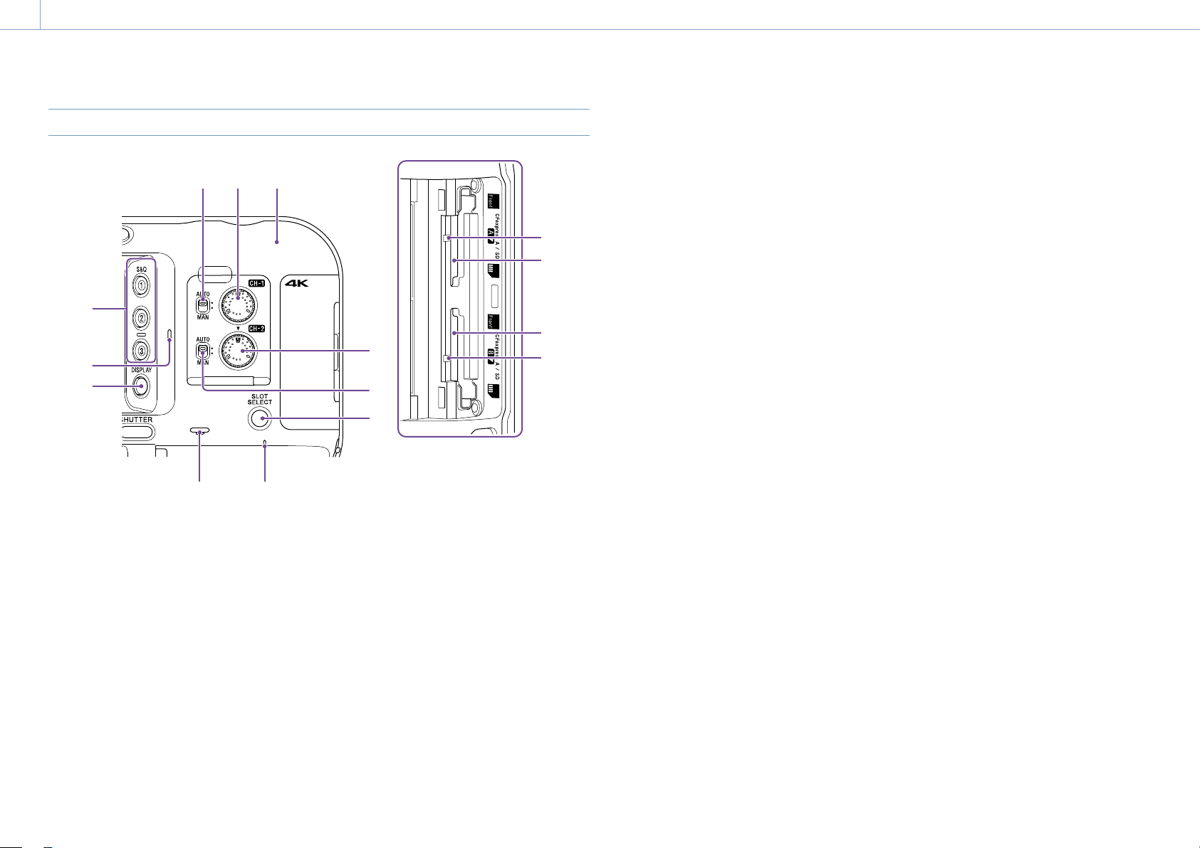
Right Rear Side and Card Slot
123
13
1. Wi-Fi antenna
2. AUDIO LEVEL (CH1) dial (page 47)
3. CH1 (AUTO/MAN) switch (page 47)
4. ASSIGN (assignable) 1 to 3 buttons
(page 49)
5. Internal microphone (page 47)
Narration microphone for recording ambient
sound.
[Tip]
This microphone is disabled when the handle is
attached, and the handle internal microphone becomes
active (page 7).
6. DISPLAY button (page 11)
7. Built-in speaker (page 34)
11
15
10
9
8. POWER indicator (page 34)
9. SLOT SELECT (memory card slot (A)/(B)
select) button (page 34)
10. CH2 (AUTO/MAN) switch (page 47)
11. AUDIO LEVEL (CH2) dial (page 47)
12. Access indicator A (page 26)
13. CFexpress Type A/SD card slot (A)
(page 26)
14. CFexpress Type A/SD card slot (B)
(page 26)
15. Access indicator B (page 26)
Page 7
1. Overview: Location and Function of Parts
16
18
19
7
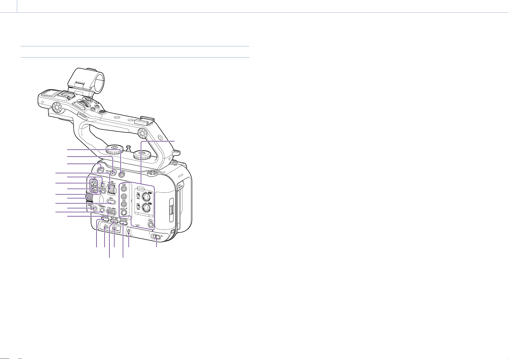
Handle, Rear, and Connector Block
10
10
9
10
11
1 2
1 3
1 4
15
20
1. Handle HOLD switch (page 97)
Use to disable operation of the controls on the
handle.
[Tip]
Can also be set for the handle record START/STOP
button only.
2. Handle record START/STOP button
3. Handle internal microphone
10
4 3 2 1
5
6
7
8
20
21
22
23
24
25
26
4. Multi-interface shoe
For details about accessories supported by
the multi-interface shoe, contact your sales
representative.
5. Handle assignable dial (page 49)
6. Handle zoom lever (page 98)
17
7. ASSIGN (assignable) 7 to 8 buttons
(page 49)
8. Multi selector (8-way D-pad and apply
buttons)
9. Accessory shoe (page 7)
10. Accessory attachment screw holes
(1/4inch)
Compatible with 1/4-20 UNC screws (length of
6mm or less).
[Note]
Use of screws longer than 6mm may damage exterior
parts.
11. Recording/tally lamp (rear) (page 34)
12. BATT RELEASE button (page 17)
13. Air inlet
[Note]
Do not cover the air inlet.
14. Battery pack attachment (page 17)
15. USB-C connector (page 62)
16. INPUT2 (audio input 2) connector
(page 47)
17. INPUT1 (audio input 1) connector
(page 47)
18. INPUT2 (LINE/MIC/MIC+48V) switch
(page 47)
19. INPUT1 (LINE/MIC/MIC+48V) switch
(page 47)
20. Screw holes for external devices
Compatible with M3 screws (length of 4mm
or less).
[Note]
Use of screws longer than 4mm may damage the
exterior surface.
21. HDMI OUT connector (page 111)
22. SDI OUT connector (page 111)
23. TC IN/TC OUT (timecode input/output)
connector (page 112)
24. REMOTE connector
Connect to general-purpose LANC jack
accessory.
25. USB/multi connector (page 113)
26. DC-IN connector (standard DC jack)
(page 18)
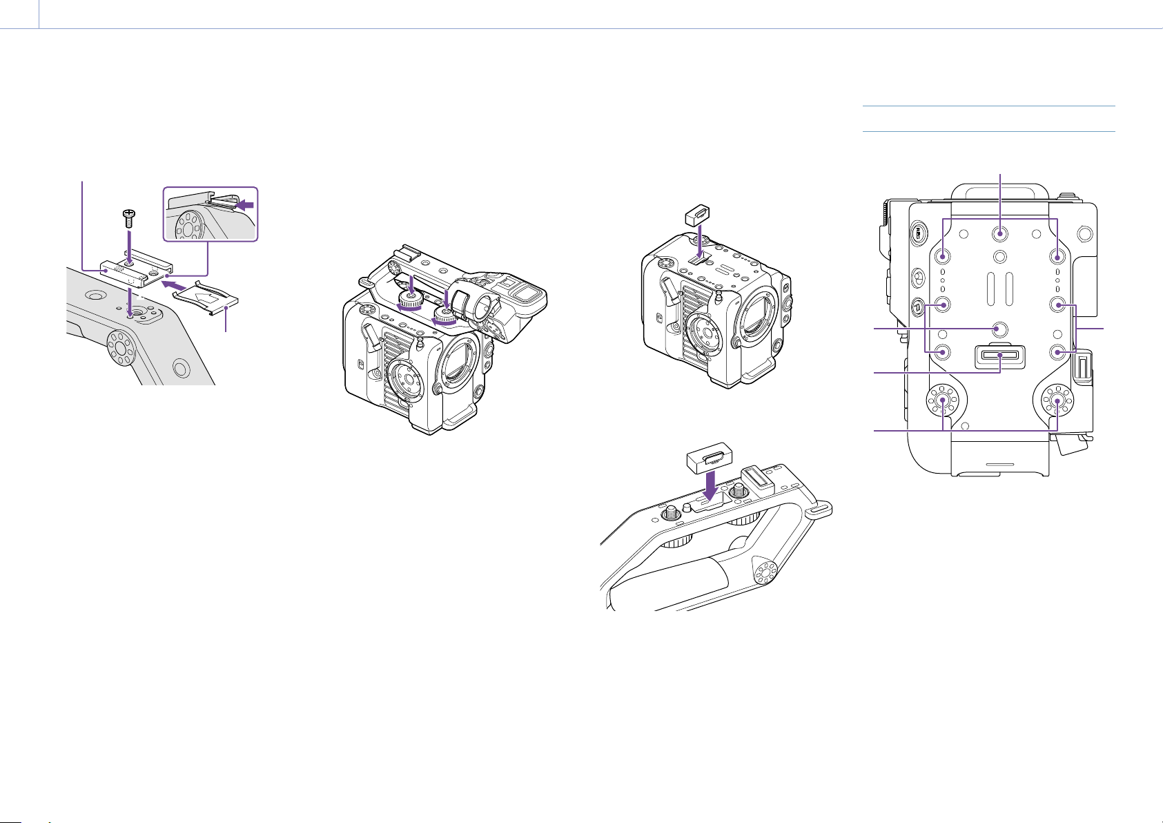
Attaching the accessory shoe
1 Lift the front edge of the shoe spring, and
pull the spring in the opposite direction to
the arrow engraved on the spring.
Shoe spring
1
Accessory shoe
2 Position the accessory shoe on the
accessory shoe mount, aligning the
protrusions on the shoe with the
corresponding points on the mount, and
tighten the four screws.
Page 8
1. Overview: Location and Function of Parts
2
2
2
2
8
3 Insert the shoe spring in the direction of
the arrow so that the U-shaped portion
fits onto the end of the accessory shoe.
Accessory shoe
3
232
Shoe spring
Removing the accessory shoe
Remove the shoe spring as described in step1
in “Attaching the Accessory Shoe,” unscrew the
four screws, and remove the accessory shoe.
Attaching the handle
Position the handle so that the handle
connector and screw holes are aligned, push
in and turn the handle attachment screws
clockwise to attach the handle to the unit.
You can also tighten the two handle
attachment screws by turning them clockwise
using a hex wrench (4mm).
[Note]
Make sure the two handle attachment screws are
securely tightened before using the handle. The handle
may fall off from the camcorder if the screws are not
tightened securely.
Removing the handle
Remove using the reverse of the attachment
procedure.
Attaching the handle connector
protective cap (supplied)
When using the camcorder with the handle
removed, protect the connector using the
supplied protective cap.
[Tip]
When attaching the handle, stow the supplied protective
cap on the bottom of the handle.
Top Side
1
1. Handle connector
2. Accessory attachment screw holes
(1/4inch)
Compatible with 1/4-20 UNC screws (length of
6mm or less).
[Note]
Use of screws longer than 6mm may damage exterior
parts.
Protecting the connector terminals
Attach the cover to unused connectors to
protect the connector terminals.
Page 9
1. Overview: Location and Function of Parts
1 2
2
3
4 5
4
1
8
6
5
9
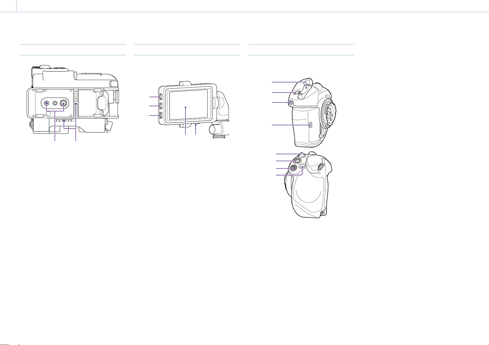
Bottom Side
1. Tripod screw holes (1/4inch, 3/8inch)
Compatible with 1/4-20 UNC screws and
3/8-16 UNC screws. Attach to a tripod (option,
screw length of 5.5mm or less).
2. Air outlet
[Note]
Do not cover the air outlet.
Viewfinder
For details about attaching the viewfinder
(supplied), see page 19.
1
1. PEAKING button
2. ZEBRA button
3. ASSIGN (assignable) 9 button (page 49)
4. Touch panel
Touch operations can be disabled using
an assignable button or using the menu
(page 10).
5. MIRROR switch
Grip Remote Control
For details about attaching the grip remote
control (supplied), see page 20.
2
3
7
1. Zoom lever
2. ASSIGN (assignable) 4 button (page 49)
3. Grip assignable dial (page 49)
4. ASSIGN (assignable) 6 button (page 49)
5. Grip rotation lever (page 21)
6. Record START/STOP button
7. Multi selector (8-way D-pad and apply
buttons)
8. ASSIGN (assignable) 5 button (page 49)
Page 10

1. Overview
10
Using the Touch Panel
Touch Panel Usage Precautions
The viewfinder of the unit is a touch panel,
which you operate directly by touch using
your finger.
The touch panel is designed to be touched
lightly with your finger. Do not press the
panel with force or touch it using sharpedged or pointed objects (nail, ballpoint
pen, pin, etc.).
The touch panel may not respond when
touched in the following circumstances. Also
note that these may cause a malfunction.
Operation using the tips of finger nails
Operation while other objects are
touching the surface
Operation with a protective sheet or
sticker attached
Operation with water droplets or
condensation on the display
Operation using wet or sweaty fingers
Touch Panel Gestures
Tap
Lightly touch an item, such as an icon or menu
item, using your finger and then immediately
remove your finger.
Drag
Touch the screen and slide your finger to
the desired position of the screen, and then
remove your finger.
Flick/swipe
Touch the screen and quickly flick/swipe your
finger up, down, left, or right.
Configuring the Touch Panel
Touch panel operation can be enabled/
disabled using Touch Operation (page 97)
in the Technical menu.
[Tip]
If the display content continues beyond the edges of the
screen, you can drag or flick the display content to scroll.
Page 11
1. Overview
3 42
9 10
75
18 19 20 21 22 23 24 25 26 27 28
29
30
31
32
33
34
35
36
137
11
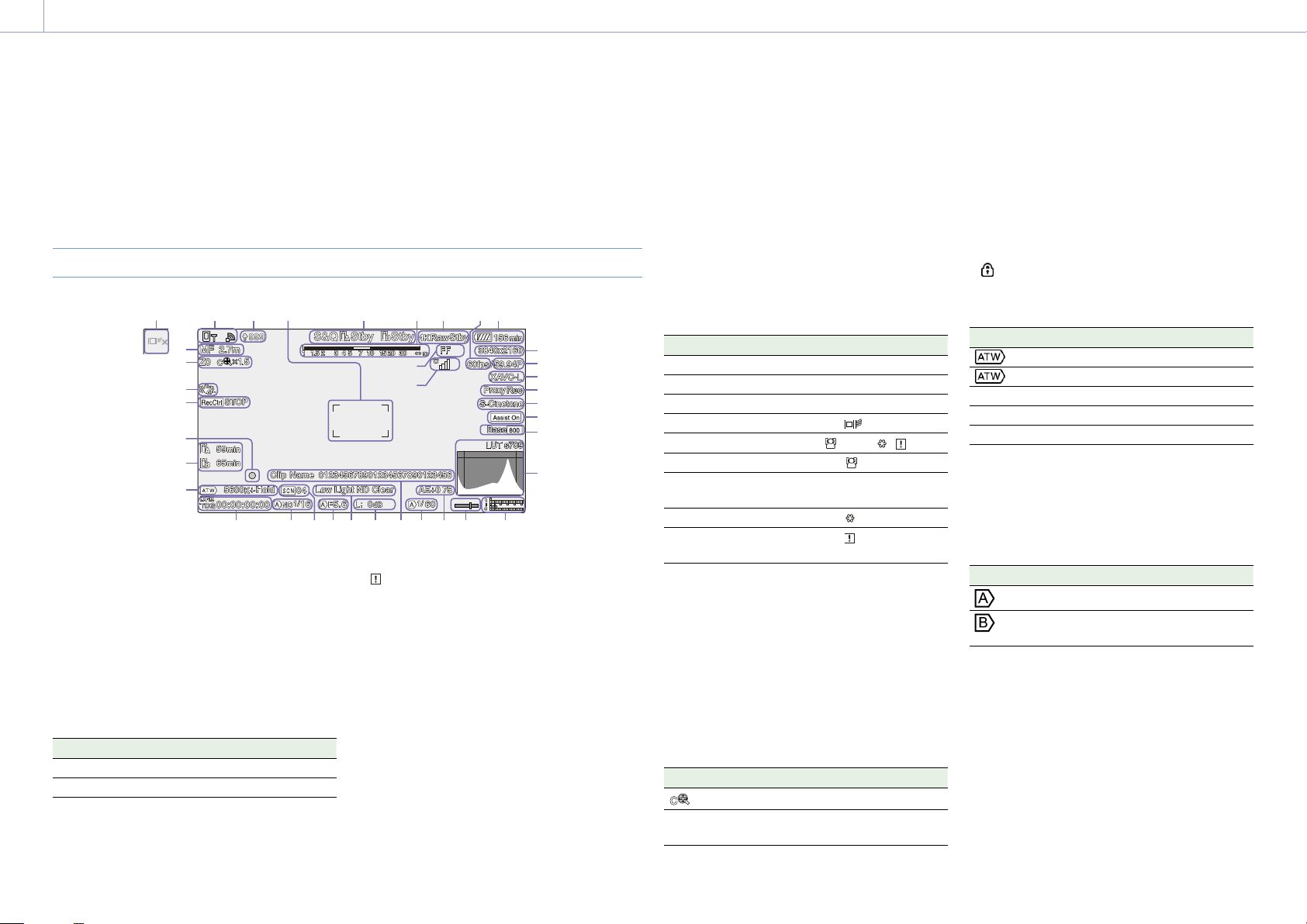
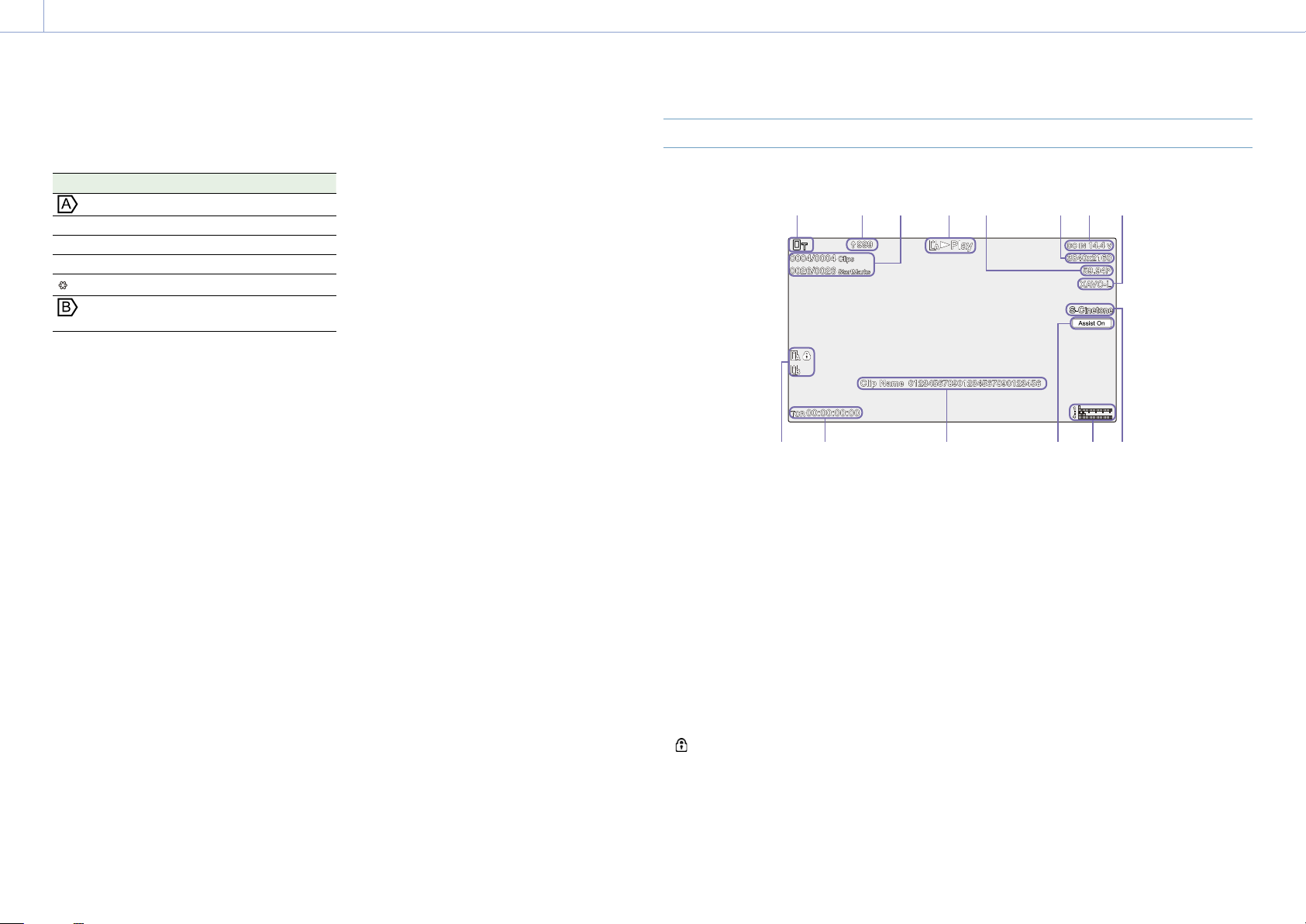
Screen Display
During shooting (recording/standby) and playback, the camcorder status and settings are
superimposed on the image displayed in the viewfinder.
You can show/hide the information using the DISPLAY button. Even when hidden, it will appear
while performing direct menu (page 49) operations.
You can also select to show/hide each item independently (page 91).
Information Displayed on the Screen While Shooting
11
12
13
14
15
16
17
1. Network status indicator (page 13)
Displays the network connection status as an
icon.
2. Upload indicator/remaining files indicator
(page 64)
3. Focus area indicator (page 38)
Displays the focus area for auto focus.
4. Recording mode, slot A/B, Interval Rec
recording interval indicator (page 50)
Display Meaning
Rec
Stby Recording standby
Recording
5. Depth-of-field indicator
6. Imager scan mode indicator (page 24)
A
between the image circle size of the lens and
the effective picture size imager scan mode
setting.
When Imager Scan Mode is set to FF, a “C”
mark is displayed in modes with narrower
angle of view (cropped).
Cropping occurs in the following modes.
7. RAW output operation status indicator
Displays the output status of the RAW signal.
6
8
mark is displayed if there is a mismatch
When the recording format is 3840×2160
and S&Q Motion frame rate is 100fps or
120fps
When Codec is set to RAW or RAW & XAVC-I
and the RAW output format is 3840×2160
(page 58)
8. UWP-D series status indicator
(page 13)
Displays the RF level signal strength as an icon
when a UWP-D series device is connected
to the MI shoe configured for digital audio
transfer.
9. Slow & Quick Motion shooting frame rate
indicator (page 50)
10. Remaining battery capacity/DC IN voltage
indicator (page 17)
11. Focus mode indicator (page 41)
Meaning Display
Focus Hold mode Focus Hold
MF mode MF
AF mode AF
Realtime tracking AF mode
Face/eye detection AF (AF/ /Only/ / )
Face/eye detection icon
Face/eye detection AF
icon
Saved tracking face icon
AF paused icon during
face/eye detection AF
1) Displayed when there is no saved tracking face and a
face is not detected, or when there is a saved tracking
face but the tracking target face is not detected.
Only
1)
12. Zoom position indicator (page 36)
Displays the zoom position in the range 0
(wide angle) to 99 (telephoto) (if a lens that
supports zoom setting display is attached).
The display can be changed to a bar indicator
or focus distance indicator (page 98).
The following items are added to the display
when Clear Image Zoom is enabled.
Display Meaning
Clear Image Zoom is enabled
Magnification
value
When using Clear Image
Zoom
13. Image stabilization mode indicator
14. SDI output/HDMI output Rec Control
status indicator (page 111)
Displays the output status of the REC control
signal.
15. Focus indicator (page 37)
16. Remaining media capacity indicator
A
icon appears if the memory card is write-
protected.
17. White balance mode indicator
Display Meaning
Auto mode
Hold Auto mode paused
W:P Preset mode
W:A Memory A mode
W:B Memory B mode
18. Timecode external lock indicator/time
data display (page 34)
Displays “EXT-LK” when locked to the
timecode of an external device.
19. ND filter indicator (page 44)
Display Meaning
Auto mode
Bokeh control mode
(page 53)
20. Scene file indicator (page 55)
21. Iris indicator
Displays the iris position (F value) (if a lens that
supports iris setting display is attached).
22. Video level warning indicator
Page 12
1. Overview: Screen Display
12
23. Gain indicator (page 43)
Displays the EI value when in Cine EI mode
(page 24).
Display Meaning
Auto mode
H Preset H mode
M Preset M mode
L Preset L mode
Temporary adjustment mode
Bokeh control mode
(page 53)
24. Clip name display (page 66)
25. Shutter indicator (page 44)
26. AE mode/AE level indicator (page 43)
27. Spirit level indicator
Displays the horizontal level in ±1° increments
up to ±15°.
28. Audio level meter
Displays the audio level of CH1 to CH4.
29. Video signal monitor (page 52)
Displays a waveform, vectorscope, and
histogram.
The orange line indicates the set value of the
zebra level.
In Cine EI mode (page 24), it displays the
LUT type of the signal being monitored.
30. Base Sensitivity indicator/Base ISO
indicator (page 43)
In Custom mode (page 24), it displays the
base sensitivity set using Base ISO/Sensitivity
on the Main status screen or ISO/Gain/EI
>Base Sensitivity in the Shooting menu of the
full menu.
In Cine EI mode (page 24), it displays
the Base ISO sensitivity set using Base ISO/
Sensitivity from the Main status screen or ISO/
Gain/EI >Base ISO in the Shooting menu of the
full menu.
31. Gamma display assist/monitor LUT
indicator
Displays the gamma display assist status. The
gamma display assist function can be turned
on/off by assigning Gamma Display Assist to
an assignable button (page 49).
In Cine EI mode (page 24), it displays the
monitor LUT setting (page 79).
32. Base look indicator (page 55)
Displays the base look setting.
In Cine EI mode (page 24), it displays the
video signal to record on the memory cards
(page 79).
33. Proxy status indicator
34. Recording format (codec) indicator
(page 80)
Displays the name of the format for recording
on the memory cards.
35. Recording format (frame rate and scan
method) indicator
36. Recording format (picture size) indicator
(page 80)
Displays the picture size for recording on the
memory cards.
37. Realtime tracking AF stop button
(page 42)
Information Displayed on the Screen During Playback
The following information is superimposed on the playback picture.
1
9 10 11 12 13 14
1. Network status indicator
2. Upload indicator/remaining files indicator
3. Clip number/total number of clips
4. Playback status indicator
5. Playback format (frame rate and scan
method) indicator
6. Playback format (picture size) indicator
7. Remaining battery capacity/DC IN voltage
indicator
8. Playback format (codec) indicator
9. Media indicator
A
icon appears if the memory card is write-
protected.
10. Time data display
11. Clip name display
12. Gamma display assist indicator
2 3 4 5 6 7 8
13. Audio level meter
Displays the playback audio level.
14. Base Look indicator
Page 13

1. Overview: Screen Display
13
Icon Display
Network connection icon display
Network mode Connection status Icon
Access point mode Operating as an access point
Access point operation error
Station mode Wi-Fi connection
Icon changes according to the signal
strength (4 steps)
Wi-Fi disconnected (including when
establishing connection)
Wi-Fi connection error
USB tethering USB tethering connected
USB tethering disconnected
USB tethering error
UWP-D series icon display
Transmitter status Receive status Icon
Power off Not receiving
Normal transmit status Receiving
(receive level (4 steps))
Muting status Receiving (muted)
Remaining battery capacity warning
status
Muting and remaining battery capacity
warning status
Receiving
Receiving
–
(Icon flashing)
(Icon flashing)
Status Screen
You can check the settings and status of the
camcorder on the status screen. The settings
of items marked with an asterisk (*) can be
changed.
The status screen supports touch operation.
To display the status screen
Press the MENU button.
[Tip]
You can show/hide each status screen using Menu Page
On/Off (page 98) in the Technical menu.
To switch the status screen
Turn the multi-function dial.
Push the multi selector up/down
Swipe the status screen up/down.
To hide the status screen
Press the MENU button.
To change a setting
With the status screen displayed, press the
multi-function dial or multi selector to enable
selection of a setup item within a page. Select
a page number and then press to switch
pages.
You can also select items directly using touch
operation.
[Note]
You can disable changes from the status screen by
setting Menu Settings >User Menu Only (page 98) in
the Technical menu of the full menu to On.
Main Status screen
Displays the main functions of the camera and
the free space on the media.
Display item Description
S&Q Frame Rate* Slow & Quick Motion
shooting and frame rate
settings
Frequency/Scan* System frequency and
scanning method settings
Imager Scan* Scan mode of the image
sensor
Media Remain
(A)
ND Filter ND filter setting
ISO/Gain/EI ISO/Gain/Exposure Index
Base ISO/
Sensitivity*
Codec* Codec setting for recording
Media Remain (B) Remaining free space on
Scene File* Scene file in use and its File
Base Look/LUT* Base Look/LUT setting
Shutter Shutter speed or shutter
Iris Iris setting
Video Format* Picture size for recording to
RAW Output
Format*
White Balance White balance setting
Remaining free space on
media in slot A
setting
Base ISO/Base Sensitivity
setting
media in slot B
ID setting
angle setting
memory cards
Image size of the RAW
output
Page 14

1. Overview: Screen Display
14
Camera Status screen
Displays the status of various presets of the
camera.
Display item Description
White Switch<B> White balance memory B
setting
White Switch<A> White balance memory A
setting
White Switch<P> Preset White setting
ND<Preset> ND filter Preset1 to 3 settings
1)
ISO / Gain
ISO / Gain
ISO / Gain
Base ISO/
Sensitivity*
Zebra1* Zebra1 On/Off setting and
Zebra2* Zebra2 On/Off setting and
VF Gamma/
Gamma
Scene File* Scene file in use and its File
1) Exposure Index when Shooting Mode is set to Cine EI.
<L>* ISO/Gain1)<L> setting
1)
<M>* ISO/Gain1)<M> setting
1)
<H>* ISO/Gain1)<H> setting
Base ISO/Base Sensitivity
setting
level
level
Gamma category and curve
ID setting
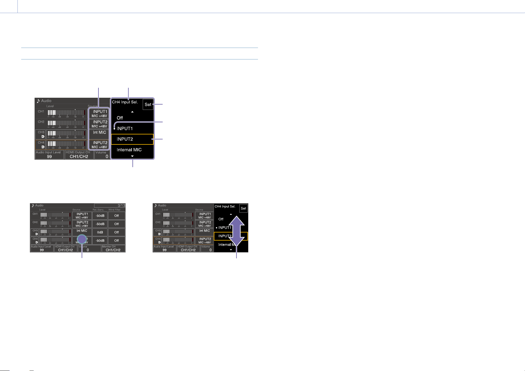
Audio Status screen
Displays the input setting, audio level meter,
and volume monitor setting for each channel.
Display item Description
CH1 Level
Control
Level Meter Audio level meter
Source* Input source
Ref./Sens.* Input reference level
Wind
Filter*
CH2 Level
Control
Level Meter Audio level meter
Source* Input source
Ref./Sens.* Input reference level
Wind
Filter*
CH3 Level
Control*
Level
Meter*
Source* Input source
Ref./Sens.* Input reference level
Wind
Filter*
CH4 Level
Control*
Level
Meter*
Source* Input source
Ref./Sens.* Input reference level
Wind
Filter*
Audio Input
Level*
HDMI Output CH* HDMI output audio channel
Volume* Headphone/built-in speaker
Auto adjustment On/Off
status
Microphone wind noise
reduction filter setting
Auto adjustment On/Off
status
Microphone wind noise
reduction filter setting
Auto adjustment On/Off
status
Audio level meter
Microphone wind noise
reduction filter setting
Auto adjustment On/Off
status
Audio level meter
Microphone wind noise
reduction filter setting
Audio input level (master
volume) setting
setting
volume setting
Display item Description
Monitor CH* Monitor channel setting
Project status screen
Displays the basic settings related to the
shooting project.
Display item Description
Frequency/Scan* System frequency and
scanning method settings
Codec* Codec setting for recording
Rec Function* Special recording function
On/Off setting and main
settings
Simul Rec* 2-slot simultaneous
recording function On/Off
status and setting
Title Prefix Title portion of the clip
name
Imager Scan* Scan mode of the image
sensor
Video Format* Picture size for recording to
memory cards
Picture Cache
Rec*
Number Numeric suffix of the clip
Shooting Mode* Shooting mode settings
RAW Output
Format*
Proxy Rec* Proxy recording function
Picture cache recording
function On/Off and cache
size setting
name
Image size of the RAW
output
On/Off setting
Monitoring Status screen
Displays the SDI and HDMI output settings.
Display item Description
SDI Signal* Output picture size
Info.
Disp.*
Color
Gamut*
HDMI Signal* Output picture size
Info.
Disp.*
Color
Gamut*
Stream Signal Output picture size
Info.
Disp.
Color
Gamut*
VF Color
Gamut*
Base Look/LUT* Base Look/LUT setting
Gamma Display
Assist*
Output display On/Off
setting
Color space setting/
Monitor LUT status
Output display On/Off
setting
Color space setting/
Monitor LUT status
Output display (Off (fixed))
Color space setting/
Monitor LUT status
Gamma display assist
setting/Color space setting/
Monitor LUT status
Gamma Display Assist on/
off setting
Page 15
1. Overview: Screen Display
15
Assignable Button Status screen
Displays the functions assigned to each of the
assignable buttons.
Display item Description
1 Function assigned to the
ASSIGN 1 button
2 Function assigned to the
ASSIGN 2 button
3 Function assigned to the
ASSIGN 3 button
4 Function assigned to the
ASSIGN 4 button
5 Function assigned to the
ASSIGN 5 button
6 Function assigned to the
ASSIGN 6 button
7 Function assigned to the
ASSIGN 7 button
8 Function assigned to the
ASSIGN 8 button
9 Function assigned to the
ASSIGN 9 button
Focus Hold
Button
Multi Function
Dial
Grip Dial Function assigned to the
Handle Dial Function assigned to the
Function assigned to the
Focus Hold button of the
lens
Function assigned to the
multi-function dial
grip assignable dial
handle assignable dial
Battery Status screen
Displays information about the battery and DC
IN source.
Display item Description
Detected Battery Type of battery
Remaining Remaining capacity (%)
Charge Count Number of recharges
Capacity Remaining capacity (Ah)
Voltage Battery voltage (V)
Manufacture
Date
Video Light
Remaining
Power Source Power supply source
Supplied Voltage Supplied power source
Date of battery manufacture
Displays the remaining
capacity of the video light
battery.
voltage
Media Status screen
Displays the remaining capacity and remaining
recording time of recording media.
Display item Description
Media A
information
Media A
remaining
capacity meter
Media A
remaining
recording time
Media B
information
Media B
remaining
capacity meter
Media B
remaining
recording time
Displays the media icon
when recording media is
inserted in slot A.
Displays the remaining
capacity of recording media
inserted in slot A expressed
as a percentage on a bar
graph.
Displays an estimate of the
remaining recording time of
the recording media
inserted in slot A in units of
minutes under the current
recording conditions.
Displays the media icon
when recording media is
inserted in slot B.
Displays the remaining
capacity of recording media
inserted in slot B expressed
as a percentage on a bar
graph.
Displays an estimate of the
remaining recording time of
the recording media
inserted in slot B in units of
minutes under the current
recording conditions.
Network Status screen
Displays the network connection status.
Display item Description
Wireless LAN Wireless network settings
and connection status
Wired LAN Wired LAN network settings
and connection status
Modem Wireless network settings
and connection status of
USB tethering
File Transfer Status screen
Displays file transfer information.
Display item Description
Auto Upload
(Proxy)
Job Status
(Remain / Total)
Total Transfer
Progress
Default Upload
Server
Current File
Transfer Progress
Current
Transferring File
Name
Server Address Address of file transfer
Destination
Directory
Auto Upload (Proxy) function
On/Off status
Remaining number of jobs
and total number of jobs
Transfer progress of all jobs
Name of Auto Upload
(Proxy) destination server
Transfer progress of current
file transfer
Name of file currently being
transferred
destination server
Destination directory of file
transfer destination server
Page 16
1. Overview: Screen Display
16
Using Touch-enabled Settings Screens
Screen layout
Operation
1 Tap a setup item.
Tap
The selection options for the value
appear.
Item
Item name
Selection options
2 Drag or flick a setting to select the value.
3 Tap the Set button or the value selection
cursor.
The value is applied and the display
returns to the previous screen.
[Tips]
Press the CANCEL/BACK button to return to the
previous value.
You can also use the multi-function dial or multi
selector.
Touch operations can also be disabled (page 97).
Set (apply) button
Mark indicating current setting
Setting selection cursor
(orange frame)
Flick
Page 17
2. Preparation
17
Power Supply
You can use a battery pack or AC power
supply from an AC adaptor.
For safety, use only the Sony battery packs and
AC adaptors listed below.
Lithium-ion battery packs
BP-U35 (supplied)
BP-U60
BP-U60T
BP-U70
BP-U90
BP-U100
Battery chargers
BC-CU1 (supplied)
BC-U1A
BC-U2A
AC adaptor (supplied)
[CAUTION]
Do not store battery packs in locations
exposed to direct sunlight, flame, or high
temperature.
[Notes]
When operating from an AC power source, use the
supplied AC adaptor.
Always set the POWER switch to the Off position
before connecting a battery or AC adaptor. If it is
connected with the POWER switch in the On position,
the camcorder may be unable to start in some cases.
If the camcorder cannot be started, set the POWER
switch to the Off position and disconnect the battery
pack or AC adaptor temporarily, then wait about
30seconds before attempting to connect again. (If
the AC adaptor is connected while the camcorder is
operating from the battery pack, it can be connected
with the POWER switch in the On position without
problem.)
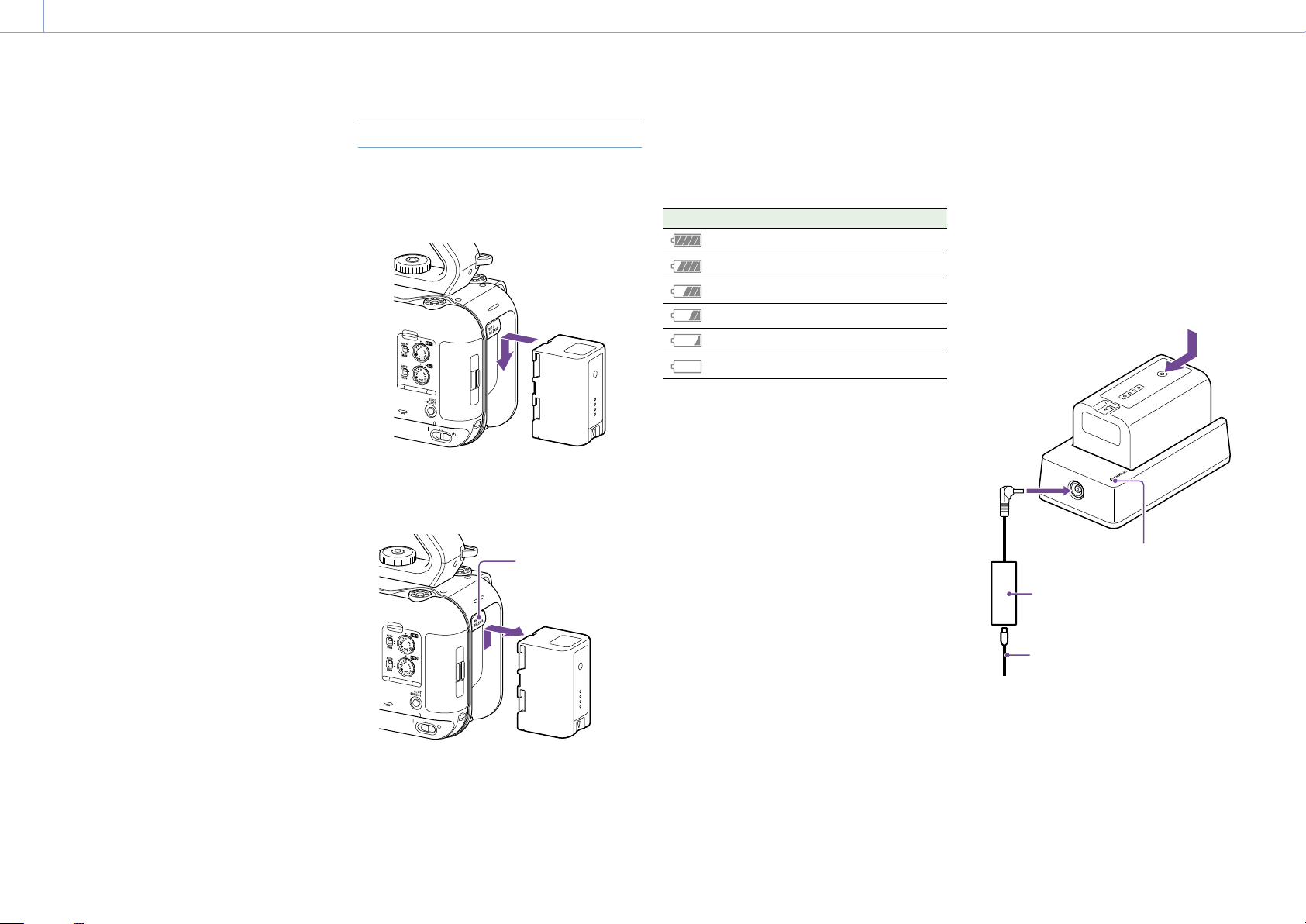
Using a Battery Pack
To attach a battery pack, plug the battery pack
into the attachment (page 7) as far as it
will go, and then slide it down to lock it into
position.
To remove a battery pack, press and hold the
BATT RELEASE button (page 7), slide the
battery pack up and then pull it out of the
attachment.
BATT RELEASE
button
[Notes]
Before attaching a battery pack, charge the battery
using the dedicated BC-CU1, BC-U1A, or BC-U2A
battery charger.
Charging a battery pack while it is warm (for example,
immediately after use) may not fully recharge the
battery.
Checking the remaining capacity
When shooting/playing using a battery pack,
the remaining battery capacity is displayed in
the viewfinder (page 11).
Icon Meaning
91% to 100%
71% to 90%
51% to 70%
31% to 50%
11% to 30%
0% to 10%
The camcorder indicates the remaining
capacity by calculating the available time with
the battery pack if operation is continued at
the current rate of power consumption.
If the battery pack charge becomes low
If the remaining battery charge falls below a
certain level during operation (Low Battery
state), a low-battery message appears and the
recording/tally lamp starts flashing to warn
you.
If the remaining battery charge falls below
the level at which operation cannot continue
(Battery Empty state), a battery-empty
message appears.
Replace with a charged battery pack.
Changing the warning levels
The Low Battery level is set to 10% of full
battery charge and the Battery Empty level is
set to 3% by factory default. You can change
the warning level settings using Camera
Battery Alarm (page 99) in the Technical
menu of the full menu.
To charge the battery pack using the
supplied battery charger (BC-CU1)
1 Connect the AC adaptor (supplied) to the
battery charger, and connect the power
cord (supplied) to an AC power source.
2 Push the battery in and slide it in the
direction of the arrow.
The CHARGE lamp lights up orange and
charging starts.
CHARGE lamp
AC adaptor
Power cord
CHARGE lamp (orange)
Lit: Charging
Flashing: Charging error, or temperature is
outside the operating range and
charging is paused
When fully charged, the CHARGE lamp of
the battery charger turns off.
Always use genuine Sony batteries.
Page 18
2. Preparation: Power Supply
18
Charging time
Approximate time (minutes) required when
you charge a fully discharged battery pack.
Battery pack Full charge time
BP-U35 120 minutes
[Note]
If the AC adaptor is disconnected from the battery
charger and the battery is left connected to the battery
charger, the battery will start to discharge.
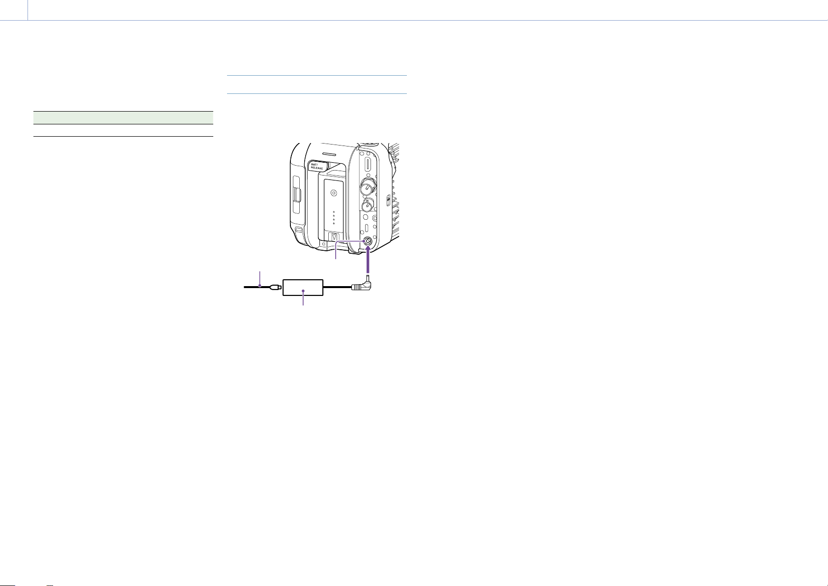
Using AC Power
Connecting the camcorder to an AC power
source allows use without worrying about the
need to recharge the battery pack.
Power cord
Connect the AC adaptor to the DC IN
connector on the camcorder, and connect the
power cord (supplied) to an AC power source.
If the output voltage from the AC
adaptor becomes low
DC IN connector
AC adaptor
Changing the warning voltages
The DC Low Voltage1 level is set to 16.5V and
the DC Low Voltage2 level is set to 15.5V by
factory default. You can change the warning
level settings using Camera DC IN Alarm
(page 99) in the Technical menu.
AC adaptor
Do not connect and use an AC adaptor in a
confined space, such as between a wall and
furniture.
Connect the AC adaptor to the nearest AC
power source. If a problem occurs during
operation, immediately disconnect the
power cord from the AC power source.
Do not short-circuit the metal parts of the
plug of the AC adaptor. Doing so will cause
a malfunction.
The battery cannot be charged while
attached to the camcorder, even if the AC
adaptor is connected.
When disconnecting the AC adaptor from
the unit, grasp the plug and pull it straight
out. Pulling on the cable may cause a
malfunction.
If the output voltage from the AC adaptor falls
below a certain level during operation (DC Low
Voltage1 state), a message appears informing
you that the AC adaptor output voltage has
dropped, and the recording/tally lamp starts
flashing.
If the output voltage from the AC adaptor falls
below the level at which operation cannot
continue (DC Low Voltage2 state), a message
appears informing you that the AC adaptor
output voltage is too low.
If this occurs, the AC adaptor may be faulty.
Check the AC adaptor, as required.
Page 19
2. Preparation
19
Attaching Devices
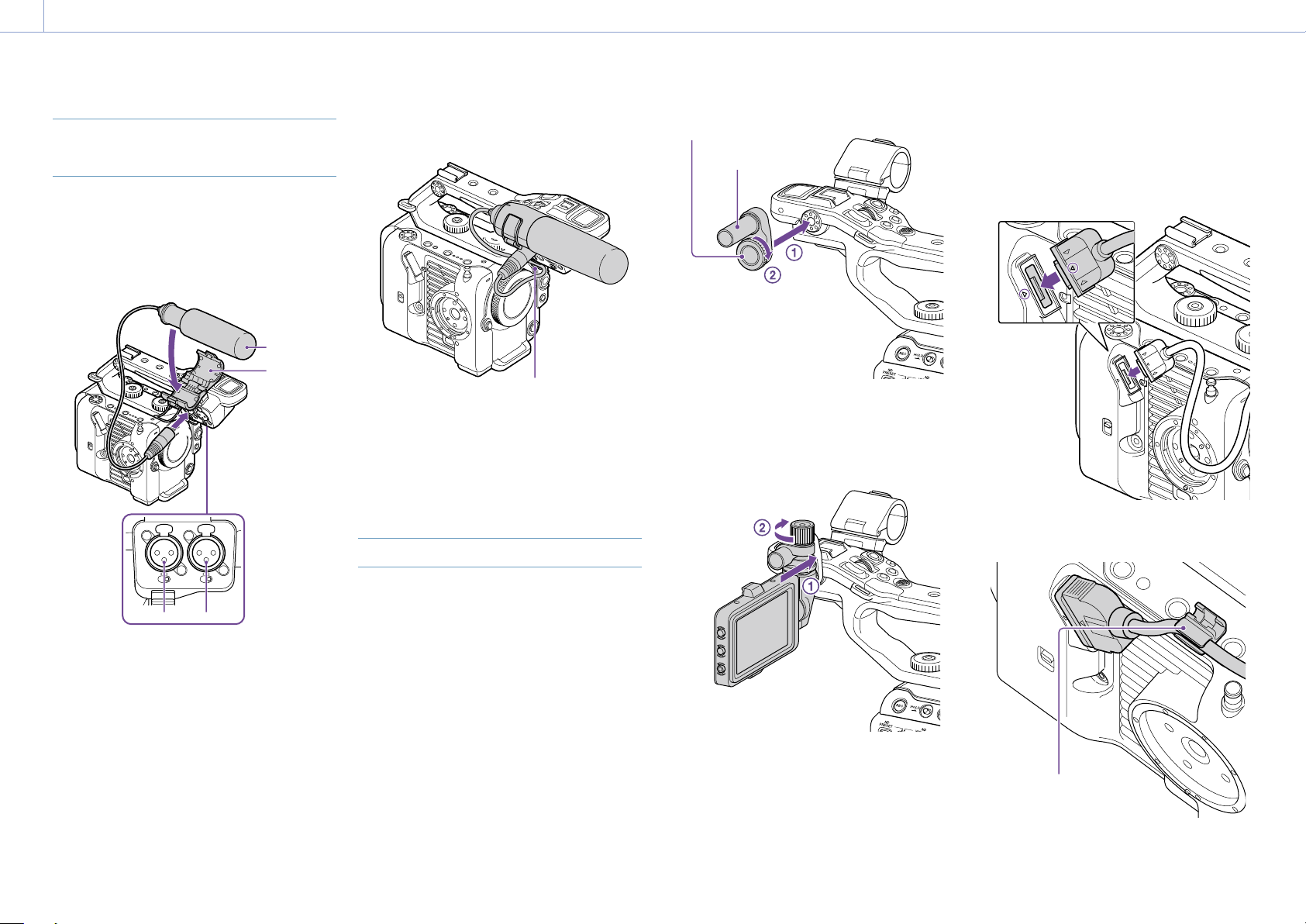
Attaching a Microphone (sold
separately)
1 Place the microphone in the microphone
holder.
2 Connect the microphone cable to the
INPUT1 or INPUT2 connector.
1
2
1
2
LINE MIC
LINE MIC
+48V
MIC
INPUT1 INPUT2
+48V
MIC
INPUT
Microphone
Microphone
holder
3 Place the microphone cable into the cable
holder as shown in the diagram.
Cable holder
[Tips]
If you cannot attach the microphone securely, use the
spacer supplied with the microphone.
Depending on the type of lens attached, the tip of the
microphone may be visible in the camcorder image.
Adjust the position of the microphone.
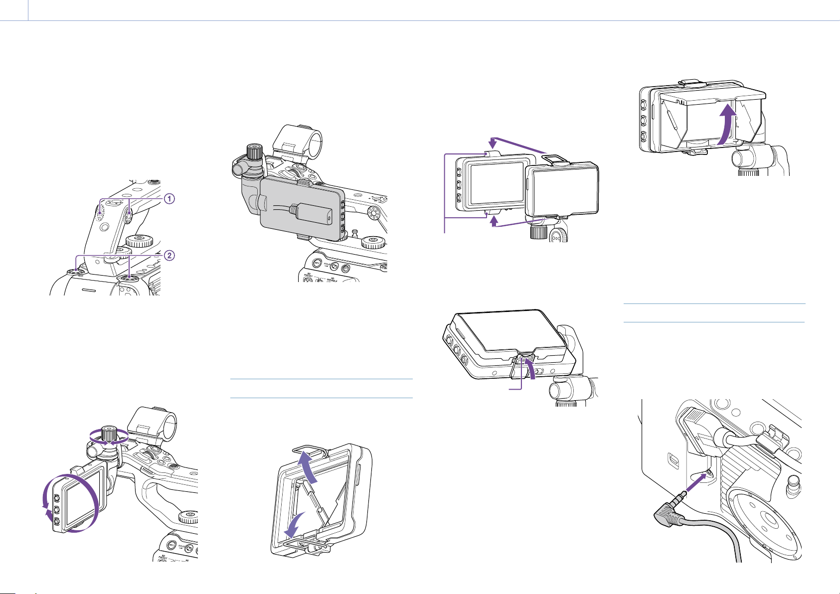
Attaching the Viewfinder
[Note]
Attach/remove the viewfinder while the camcorder is
turned off.
Screw
Viewfinder mounting
clamp adaptor
2 Mount the viewfinder clamp onto the
viewfinder mounting clamp adaptor (),
and turn the locking knob clockwise to
secure it in position ().
3 Align the mark on the camcorder with
the mark on the viewfinder connector,
and insert the cable.
Make sure that the mark is the outer
side before inserting the connector.
4 Place the cable into the cable holder as
shown in the diagram.
Attaching the viewfinder to the front of
the handle
1 Insert the viewfinder mounting clamp
adaptor in the viewfinder attachment of
the handle (), and turn the screw
(supplied) clockwise to secure it in
position ().
The mounting clamp adaptor can be
freely attached in 45° increments, but the
position where the attachment point is
directly above the screw is recommended.
[Note]
Be sure to securely tighten the locking knob when using
a viewfinder. The viewfinder may fall off if the locking
knob is not tightened securely.
Cable holder
Page 20
2. Preparation: Attaching Devices
20
Attaching the viewfinder to the rear of
the handle
There are two attachment points each on
the rear of the handle () and rear of the
camcorder () for attaching a viewfinder.
Attach the viewfinder in the same way
described in “Attaching the viewfinder to the
front of the handle.”
Adjusting the viewfinder position
Tilt the viewfinder up/down/forward/
backward to adjust the angle of the
viewfinder.
You can use the MIRROR switch to flip the
image when viewing from the front of the
camcorder, for example.
[Tip]
When the unit is not being used or is being transported,
it is recommended that the viewfinder be moved to
the position in the following diagram to protect the
viewfinder.
Removing the viewfinder
Loosen the viewfinder locking knob, and
use the reverse procedure of attaching the
viewfinder.
Attaching the Viewfinder Hood
2 Attach the metal clip on the top of the
viewfinder hood to the hook on the top of
the viewfinder, and attach the metal clip
on the bottom of the viewfinder hood to
the hook on the bottom of the viewfinder.
Attachment hooks
3 Push the lock plate on the bottom of the
viewfinder hood in the direction of the
arrow to lock the viewfinder hood into
position.
Lock plate
[Note]
When moving the viewfinder, hold the body of
the viewfinder and then move it. Do not grasp the
viewfinder hood.
Removing the viewfinder hood
Unclip the viewfinder hood lock, and remove
the viewfinder hood from the viewfinder.
Attaching the Grip Remote Control
[Note]
Attach/remove the grip remote control while the
camcorder is turned off.
1 Connect the cable to the grip remote
control connector.
1 Open the metal clips on the viewfinder
hood.
Opening the viewfinder hood
Pull the bottom center of the viewfinder hood
out towards you, and then pull up to open the
hood.
Page 21
2. Preparation: Attaching Devices
21
2 Align the grip remote control attachment
of the camcorder and the mount index
mark on the grip (), attach the grip to
the camcorder, and turn it
counterclockwise slowly ().
A click sound can be heard when it locks
into position.
Index mark
[Note]
If it cannot be attached correctly, re-attach it without
applying excessive force to the grip remote controller or
the camcorder.
[Note]
If the cable is not placed under the slit, changing the
angle of the grip attachment may place excessive force
on the cable or the cable may get caught in the rotating
mechanism.
Adjusting the angle of the grip remote
control
You can adjust the angle of the grip remote
control over a range shown in the following
diagram to suit your shooting style.
Standard position
Rotated toward rear (83° max.)
1 Move the grip rotation lever to the
position shown in the diagram and rotate
the grip while pressing the lever.
[Notes]
After changing position, always check that the grip is
securely positioned.
You cannot adjust the angle beyond the adjustment
range. Do not use excessive force when rotating the
grip.
Holding the grip (recommended
method)
There are no rules about how to hold the grip,
but the following example shows a way for
easy operation of the grip.
When using the ASSIGN 5 button or multi
selector
3 Insert the cable connected in step2 under
the slit of the grip remote control as
shown in the diagram.
Rotated toward lens (90° max.)
2 Remove your finger from the grip rotation
lever near the desired position.
3 Move the grip slightly until you hear a
click sound, indicating the grip is secured
in position.
When the grip is secured, the grip
rotation lever returns to the original
position.
A: Operate the grip assignable dial using your
index finger.
B: Operate the multi selector and ASSIGN 5
button using your thumb.
C: Firmly hold the grip using your middle
finger, ring finger, and little finger.
Page 22
2. Preparation: Attaching Devices
22
When operating the zoom
A: Operate the zoom lever using your index
finger and middle finger.
B: Firmly hold the grip using your thumb.
C: Firmly hold the grip using your ring finger
and little finger.
Removing the grip
[Note]
When removing the grip, be sure to place the camcorder
on a flat surface, such as a desk.
1 Disconnect the cable from the grip remote
control connector.
2 Press and hold the grip remote control
release button of the camcorder, and
rotate the grip clockwise until it detaches.
Grip remote control release button
[Tip]
A rosette can be attached to both the grip attachment
point on the unit and the corresponding attachment
point on the grip.
For details about purchasing rosettes, contact your Sony
dealer.
– Camcorder side: 4-546-932- (option)
– Grip side: 4-547-089- (option)
– Attachment screws*
Camcorder side: 7-627-556- (option)
Grip side: 7-627-556- (option)
* Four screws are required for each rosette (screw holes
are indicated by the circles in the following diagram).
Use of screws other than those specified may
damage exterior parts.
Camcorder
side
Grip side
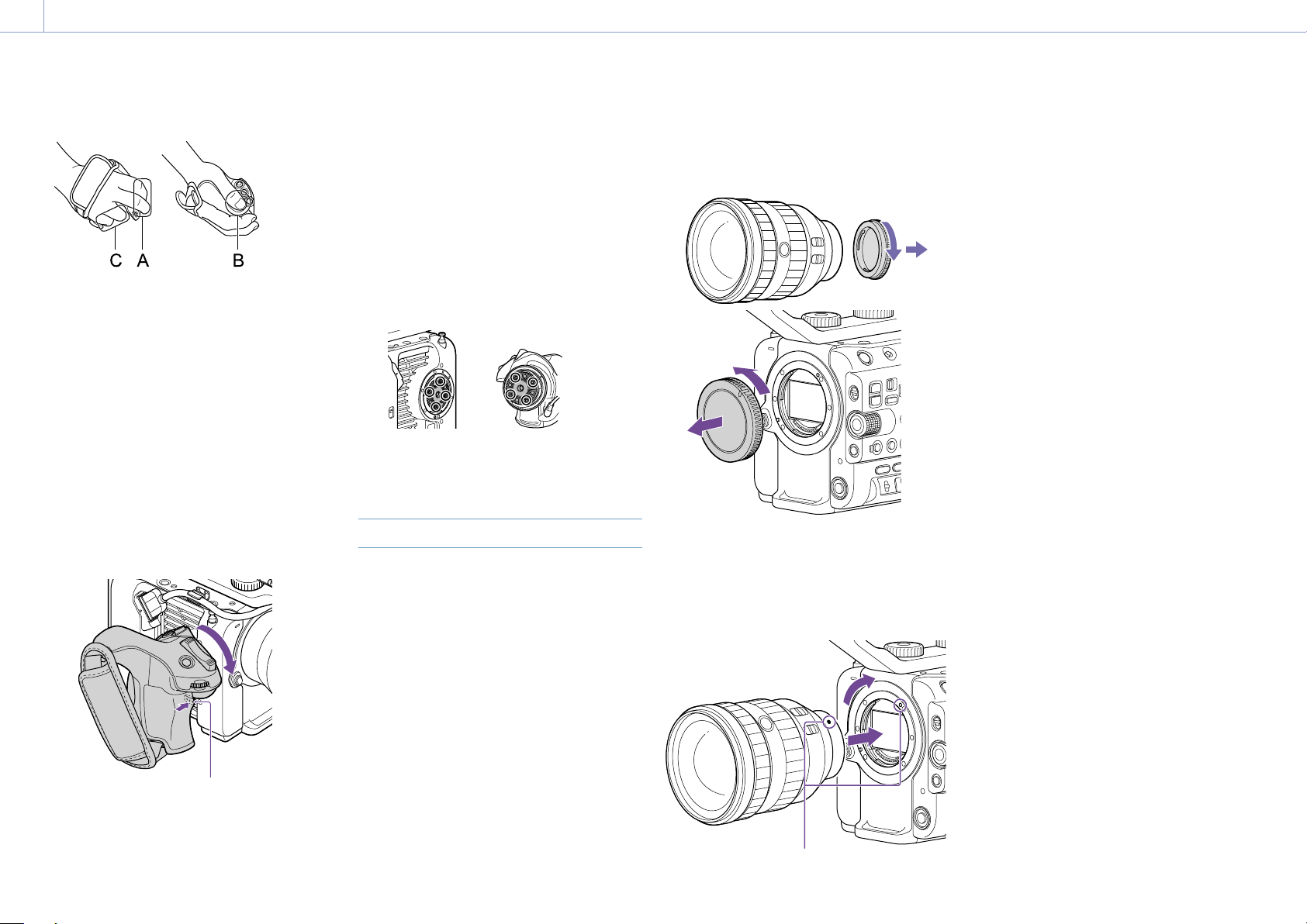
Attaching a Lens
[CAUTION]
Do not leave the lens facing the sun. Direct
sunlight can enter through the lens, be
focused in the camcorder, and may cause a
fire.
[Notes]
Attach/remove a lens while the camcorder is turned
off.
A lens is a precision component. Do not place the lens
on a surface with the lens mount face down. Attach
the supplied lens mount cap.
[Tip]
For details about lenses supported by the camcorder,
contact your Sony service representative.
Attaching an E-mount lens
1 Remove the lens cap and cover from the
camcorder and the lens.
2 Align the lens mount mark (white) with
the camcorder, carefully insert the lens,
and then turn the lens clockwise.
A click sound can be heard when it locks
into position.
[Note]
Do not press the lens release button when attaching a
lens.
Attaching an A-mount lens
To use an A-mount lens, attach a lens mount
adaptor (option) and then attach the A-mount
lens.
[Note]
When using an A-mount lens, the iris is set manually
and focus is set to MF.
Removing a lens
Remove a lens using the following procedure.
1 Press and hold the lens release button
and turn the lens counterclockwise while
supporting the lens.
2 Pull the lens out in the forward direction.
[Notes]
When removing a lens, align the mount mark on the
lens lock ring with the mount mark on the camcorder.
Grasp the lens securely in your hand to prevent the
lens from falling.
If another lens will not be attached immediately,
always attach the body cap.
Iris adjustments for lenses with Auto Iris
switch
When the lens Auto Iris is set to AUTO, the
iris is adjusted automatically and can also be
adjusted manually from the camcorder.
When the lens Auto Iris is set to MANUAL,
the iris can only be adjusted using the lens
ring. Iris operation from the camcorder has
no effect.
Mount marks (white)
Page 23

2. Preparation: Attaching Devices
23
Focus adjustments for lenses with focus
switch
When the lens focus switch is set to AF/MF
or AF, the focus is adjusted automatically
and can also be adjusted manually from a
remote control unit.
When the lens focus switch is set to MF, the
focus is adjusted using the lens ring and can
also be adjusted manually from a remote
control unit.
[Note]
When using an A-mount lens, manual adjustment
from a remote control unit may not be available.
When the lens focus switch is set to Full
MF, the focus can only be adjusted using
the lens ring. Focus operation from the
camcorder has no effect.
Attaching to a tripod
Use the tripod screw holes on the camcorder
when attaching to a tripod. Using the tripod
mount on the lens may cause damage.
Page 24

2. Preparation
24
Configuring Basic Camcorder Operation
The initial settings screen appears in the
viewfinder the first time the camcorder is
turned on or after the backup battery has
become completely discharged.
Set the date and time of the internal clock
using this screen.
Time Zone
Time Zone sets the time difference from UTC
(Coordinated Universal Time). Change the
setting as required.
Setting the Date and Time
Use the multi selector (page 7) or the
multi-function dial (page 5) to select items
and settings, then press the multi selector
apply button or multi-function dial to apply
the settings and start the clock running.
Once the settings screen is closed, you
can change the date, time, and time zone
settings using Clock Set (page 104) in the
Maintenance menu.
[Notes]
If the clock setting is lost because the backup battery
becomes fully discharged due to power being
disconnected for an extended period (no battery pack
and no DC IN power source), the initial settings screen
will be displayed when you next turn the camcorder
on.
While the initial settings screen is displayed, no other
operation, except turning the power off, is permitted
until you finish the settings on this screen.
The camcorder has a built-in rechargeable battery for
storing the date, time, and other settings even when
the camcorder is turned off.
Before shooting, configure the basic operation
of the camcorder on the Project status screen
to suit the application.
Shooting Mode
You can switch the shooting mode between
“Custom mode” to create images flexibly onsite, and “Cine EI mode” (where the camcorder
is operated similarly to a film camera, with
footage developed in post production).
Set the shooting mode using Shooting Mode
(page 14) on the Project status screen.
[Tip]
You can also set the shooting mode using Base Setting
>Shooting Mode (page 80) in the Project menu of the
full menu.
Custom mode
In Custom shooting mode, you can select the
video standard.
You can set the video standard using Base
Setting >Target Display (page 80) in the
Project menu of the full menu.
SDR(BT.709): Shooting according to HD
broadcast standard
HDR(HLG): Shooting according to next
generation 4K broadcast standard
For details, see page 55.
Cine EI mode
When the shooting mode is set to Cine EI
mode, select the base color space for the
recording signal and output signal. The color
space selected here is the color space of the
video output when MLUT is set to Off.
You can set the color space using Cine EI
Setting >Color Gamut (page 81) in the
Project menu of the full menu.
S-Gamut3.Cine/SLog3: Easy to adjust color
gamut for digital cinema (DCI-P3).
S-Gamut3/SLog3: Sony wide color gamut
that covers the ITU-R BT.2020 color space.
For details, see page 57.
[Notes]
Cine EI mode has the following limitations.
Functions that cannot be adjusted automatically
(tracking)
– White balance
– Gain
– Shutter
Functions that cannot be configured
– ISO sensitivity/gain (set to base ISO sensitivity
(fixed))
– Paint/Look menu settings (excluding Base
Look)
– Scene File (disabled)
The following functions are available in Cine EI mode
only (page 57).
Exposure Index
Monitor LUT
System Frequency
Set the system frequency using Frequency/
Scan (page 14) on the Project status screen.
The camcorder may reboot automatically after
switching, depending on the selected value.
[Tip]
You can also set the system frequency using Rec Format
>Frequency (page 80) in the Project menu of the full
menu.
[Note]
You cannot switch the system frequency during
recording or playback.
Imager Scan Mode
You can set the effective picture size and
resolution of the image sensor.
Set the scan mode using Imager Scan
(page 14) on the Project status screen.
FF: Full-frame size.
S35: Super 35mm size.
[Tip]
You can also set the scan mode using Rec Format
>Imager Scan Mode (page 80) in the Project menu of
the full menu.
[Notes]
You cannot switch the imager scan mode during
recording or playback.
When set to S35, the video format is restricted to
1920×1080.
Codec
Set the codec using Codec (page 14) on the
Project status screen.
[Tip]
You can also set the codec using Rec Format >Codec
(page 80) in the Project menu of the full menu.
[Note]
You cannot switch the codec during recording or
playback.
Page 25

2. Preparation: Configuring Basic Camcorder Operation
25
Video Format
You can set the video format for recording.
Set the video format using Video Format
(page 14) on the Project status screen.
[Tip]
You can also set the video format using Rec Format
>Video Format (page 80) in the Project menu of the
full menu.
[Notes]
You cannot switch the video format during recording
or playback.
Restrictions may apply to the signal from the SDI OUT
and HDMI OUT connectors, depending on the video
format setting.
Page 26

2. Preparation
26
Using Memory Cards
The camcorder records audio and video on CFexpress Type A memory cards (available separately)
or SDXC memory cards (available separately) inserted in the card slots. The memory cards are
also used for proxy recording and storing/loading settings, and when upgrading (software
update).
About CFexpress Type A Memory Cards
Use the Sony CFexpress Type A memory cards* listed in “Recommended Media” (page 27) in
the camcorder.
For details on operations with media from other manufacturers, refer to the operating
instructions for the media or consult the manufacturer’s information.
* Referred to as “CFexpress cards” in this document.
About SDXC memory cards
Use the SDXC memory cards* listed in “Recommended Media” (page 27) in the camcorder.
* Referred to as “SD cards” in this document.
Page 27

2. Preparation: Using Memory Cards
27
Recommended Media
The guaranteed operating conditions will vary depending on the Rec Format and Recording settings.
Yes: Operation supported
No: Normal operation not guaranteed
Recording format CFexpress
RAW Out &
XAVC-I
4096×2160
Class300
3840×2160
Class300
Normal mode 59.94P Yes No No No No No No Yes
50P Ye s No No No No No No Yes
29.97P Yes No No No No No Yes Yes
25P Ye s No No No No No Yes Ye s
24P Ye s No No No No No Yes Ye s
23.98P Yes No No No No No Yes Yes
Normal mode 59.94P Yes No No No No No No Yes
50P Ye s No No No No No No Yes
29.97P Yes No No No No No Ye s Yes
25P Ye s No No No No No Yes Ye s
23.98P Yes No No No No No Ye s Yes
S&Q (60fps or lower) 59.94P Yes No No No No No No Ye s
50P Ye s No No No No No No Yes
29.97P Yes No No No No No No Yes
25P Ye s No No No No No No Ye s
23.98P Yes No No No No No No Yes
S&Q (100fps, 120fps) 59.94P Yes No No No No No No No
50P Ye s No No No No No No No
29.97P Yes No No No No No No No
25P Ye s No No No No No No No
23.98P Yes No No No No No No No
SDXC
Type A
VPG400 Class10 U1 U3 VSC
V10
VSC
V30
VSC
V60
VSC
V90
Page 28

2. Preparation: Using Memory Cards
28
XAVC-I 4096×2160
Class300
3840×2160
Class300
Recording format CFexpress
SDXC
Type A
VPG400 Class10 U1 U3 VSC
V10
Normal mode 59.94P Yes No No No No No No Yes
50P Ye s No No No No No No Yes
29.97P Yes No No No No No Ye s Yes
25P Ye s No No No No No Yes Ye s
24P Ye s No No No No No Yes Ye s
23.98P Yes No No No No No Ye s Yes
S&Q (60fps or lower) 59.94P Yes No No No No No No Ye s
50P Ye s No No No No No No Yes
29.97P Yes No No No No No No Yes
25P Ye s No No No No No No Ye s
24P Ye s No No No No No No Ye s
23.98P Yes No No No No No No Yes
Normal mode 59.94P Yes
50P Ye s No No No No No No Yes
29.97P Yes No No No No No Ye s Yes
25P Ye s No No No No No Yes Ye s
23.98P Yes No No No No No Ye s Yes
S&Q (60fps or lower) 59.94P Yes No No No No No No Ye s
50P Ye s No No No No No No Yes
29.97P Yes No No No No No No Yes
25P Ye s No No No No No No Ye s
23.98P Yes No No No No No No Yes
S&Q (100fps, 120fps) 59.94P Yes No No No No No No No
50P Ye s No No No No No No No
29.97P Yes No No No No No No No
25P Ye s No No No No No No No
23.98P Yes No No No No No No
No No No No No No Yes
VSC
V30
VSC
V60
VSC
V90
No
Page 29

2. Preparation: Using Memory Cards
29
XAVC-I 1920×1080
Class100
Recording format CFexpress
SDXC
Type A
VPG400 Class10 U1 U3 VSC
V10
Normal mode 59.94P Yes No No No No No Ye s Yes
50P Ye s No No No No No Yes Ye s
29.97P Yes No No Ye s No Ye s Yes Yes
25P Ye s No No Yes No Yes Ye s Yes
23.98P Yes No No Ye s No Yes Ye s Yes
S&Q (60fps or lower) 59.94P Yes No No No No No Ye s Yes
50P Ye s No No No No No Yes Ye s
29.97P Yes No No No No No Ye s Yes
25P Ye s No No No No No Yes Ye s
23.98P Yes No No No No No Ye s Yes
S&Q (100fps, 120fps) 59.94P Yes No No No No No No Yes
50P Ye s No No No No No No Yes
29.97P Yes No No
25P Ye s No No No No No No Ye s
23.98P Yes No No No No No No Yes
S&Q (150fps, 180fps) 59.94P Yes No No No No No No No
50P Ye s No No No No No No No
29.97P Yes No No No No No No No
25P Ye s No No No No No No No
23.98P Yes No No No No No No No
S&Q (200fps, 240fps) 59.94P Yes No No No No No No No
50P Ye s No No No No No No No
29.97P Yes No No No No No No No
25P Ye s No No No No No No No
23.98P Yes No No No No No No No
No No No No Yes
VSC
V30
VSC
V60
VSC
V90
Page 30

2. Preparation: Using Memory Cards
30
XAVC-L 3840×2160
420
1920×1080
HD50
Recording format CFexpress
SDXC
Type A
VPG400 Class10 U1 U3 VSC
V10
Normal mode 59.94P Yes No No Ye s No Ye s Yes Yes
50P Ye s No No Yes No Yes Ye s Yes
29.97P Yes No No Ye s No Ye s Yes Yes
25P Ye s No No Yes No Yes Ye s Yes
23.98P Yes No No Ye s No Yes Ye s Yes
S&Q (60fps or lower) 59.94P Yes No No Ye s No Ye s Yes Yes
50P Ye s No No Yes No Yes Ye s Yes
29.97P Yes No No No No No Ye s Yes
25P Ye s No No No No No Yes Ye s
23.98P Yes No No No No No No Yes
S&Q (100fps, 120fps) 59.94P Yes No No No No No Ye s Yes
50P Ye s No No No No No Yes Ye s
29.97P Yes No No
25P Ye s No No No No No No Ye s
23.98P Yes No No No No No No No
Normal mode 59.94P Yes No No Ye s No Ye s Yes Yes
50P Ye s No No Yes No Yes Ye s Yes
29.97P Yes No No Ye s No Ye s Yes Yes
25P Ye s No No Yes No Yes Ye s Yes
23.98P Yes No No Ye s No Yes Ye s Yes
S&Q (60fps or lower) 59.94P Yes Ye s Yes Yes Ye s Yes Ye s Yes
50P Ye s Yes Yes Ye s Yes Ye s Yes Yes
29.97P Yes No No Ye s No Ye s Yes Yes
25P Ye s No No Yes No Yes Ye s Yes
23.98P Yes No No Ye s No Yes Ye s Yes
S&Q (100fps, 120fps) 59.94P Yes No No Ye s No Ye s Yes Yes
50P Ye s No No Yes No Yes
29.97P Yes No No No No No Ye s Yes
25P Ye s No No No No No Yes Ye s
23.98P Yes No No No No No Ye s Yes
No No No No Yes
VSC
V30
VSC
V60
Yes Yes
VSC
V90
Page 31

2. Preparation: Using Memory Cards
31
XAVC-L 1920×1080
HD50
1920×1080
HD35
Recording format CFexpress
SDXC
Type A
VPG400 Class10 U1 U3 VSC
V10
S&Q (150fps, 180fps) 59.94P Yes No No No No No Ye s Yes
50P Ye s No No No No No Yes Ye s
29.97P Yes No No No No No No Yes
25P Ye s No No No No No No Ye s
23.98P Yes No No No No No No Yes
S&Q (200fps, 240fps) 59.94P Yes No No No No No Ye s Yes
50P Ye s No No No No No Yes Ye s
29.97P Yes No No No No No No Yes
25P Ye s No No No No No No Ye s
23.98P Yes No No No No No No Yes
Normal mode 59.94P Yes Yes Ye s Yes Ye s Yes Yes Ye s
50P Ye s Yes Yes Ye s Yes Ye s Yes Yes
29.97P Yes
25P Ye s Yes Yes Ye s Yes Yes Ye s Yes
23.98P Yes Yes Ye s Yes Yes Ye s Yes Yes
S&Q (60fps or lower) 59.94P Yes Ye s Yes Yes Ye s Yes Ye s Yes
50P Ye s Yes Yes Ye s Yes Ye s Yes Yes
29.97P Yes No No Ye s No Ye s Yes Yes
25P Ye s No No Yes No Yes Ye s Yes
23.98P Yes No No Ye s No Yes Ye s Yes
S&Q (100fps, 120fps) 59.94P Yes No No Ye s No Ye s Yes Yes
50P Ye s No No Yes No Yes Ye s Yes
29.97P Yes No No Ye s No Ye s Yes Yes
25P Ye s No No Yes No Yes Ye s Yes
23.98P Yes No No No No No Ye s Yes
S&Q (150fps, 180fps) 59.94P Yes No No Ye s No Ye s Yes Yes
50P Ye s No No Yes No Yes
29.97P Yes No No No No No Ye s Yes
25P Ye s No No No No No Yes Ye s
23.98P Yes No No No No No Ye s Yes
S&Q (200fps, 240fps) 59.94P Yes No No Ye s No Ye s Yes Yes
50P Ye s No No Yes No Yes Ye s Yes
29.97P Yes No No No No No Ye s Yes
25P Ye s No No No No No Yes Ye s
23.98P Yes No No No No No No Yes
Yes Yes Ye s Yes Ye s Yes Yes
VSC
V30
VSC
V60
Yes Yes
VSC
V90
Page 32

2. Preparation: Using Memory Cards
32
Inserting a Memory Card
1 Open the media cover of the card slot
section.
2 Insert a memory card.
For CFexpress cards, the label faces to
the left.
Label
For SD cards, the label faces to the right
with the beveled corner at the bottom.
Beveled corner
The access indicator (page 6) is lit red,
then changes to green if the card is
usable.
[Note]
If the access indicator flashes red continuously and
does not change to green, temporarily turn off the
camcorder, and remove and reinsert the memory
card.
3 Close the media cover.
[Notes]
The memory card, memory card slot, and image data
on the memory card may be damaged if the card is
forced into the slot in the incorrect orientation.
When recording to media inserted in both CFexpress
Type A/SD card slots A and B, insert media in both
slots that is recommended for operation with the
format of the recording.
Ejecting a Memory Card
Open the media cover of the card slot section,
and lightly press the memory card in to eject
the card.
[Notes]
If the camcorder is turned off or the memory
card is removed while the memory card is being
accessed, the integrity of data on the card cannot
be guaranteed. All data recorded on the card may
be discarded. Always make sure the access indicator
is green or off before turning off the camcorder or
removing the memory card.
When removing a memory card immediately after
recording is finished, the memory card may be hot,
but this does not indicate a problem.
Formatting (Initializing) Memory
Cards
If an unformatted memory card or a memory
card that was formatted in a different
specification is inserted, the message “Media
Needs to be Formatted” is displayed in the
viewfinder.
Format the card using the following procedure.
1 Select Format Media (page 90) in the
TC/Media menu of the full menu.
2 Select Media(A) (slot A) or Media(B) (slot
B), then select the formatting method
(Full Format or Quick Format).
A confirmation message appears.
Full Format: Initializes the media
completely, including the data region
and data management information.
Quick Format: Initializes the data
management information of the media
only.
3 Select Execute.
A message is displayed while formatting
is in progress, and the access indicator is
lit red.
When formatting is completed, a
completion message is displayed. Press
the multi-function dial to dismiss the
message.
[Notes]
Formatting a memory card erases all data, including
recorded video data and setup files.
Messages may appear during execution depending
on the formatting process duration.
If formatting fails
Memory cards not supported by the
camcorder cannot be formatted.
A warning message is displayed. Follow
the instructions to replace the card with a
supported memory card.
To use a card formatted on the
camcorder in the slot of another device
First, make a backup of the card, then reformat
the card in the device to be used.
Checking the Remaining
Recording Time
When shooting (recording/standby), you
can monitor the remaining capacity of the
memory card in each slot using the slot A/B
remaining media indicators in the viewfinder
(page 11).
The remaining recording time is calculated
from the remaining capacity of the media
in each slot and the current video format
(recording bit rate), and is displayed in units of
minutes.
Memory card replacement timing
When the total remaining recording time on
the two memory cards becomes less than
5minutes, the message “Media Near Full”
appears, the recording/tally lamp starts
flashing, and a beep sound (headphone
output) will warn you.
Replace with media that has free space.
If you continue recording until the total
remaining recording time reaches zero,
the message changes to “Media Full” and
recording stops.
[Note]
Up to approximately 600 clips can be recorded on one
memory card.
Page 33

2. Preparation: Using Memory Cards
33
Restoring Memory Cards
If for any reason an error should occur in
a memory card, the card must be restored
before use.
When you load a memory card that needs
to be restored, a message appears on the
viewfinder screen to ask whether you want to
restore it.
Restoring a card
Turn the multi-function dial (page 5) to
select Execute, then press the multi-function
dial.
A message and progress status (%) are
displayed while formatting is in progress, and
the access indicator is lit red.
When restoration ends, a completion message
appears.
If restoration fails
Memory cards on which memory errors
have occurred cannot be restored. A
warning message is displayed. Follow the
instructions to replace the memory card.
Memory cards on which memory errors
have occurred may become usable if they
are reformatted.
In some cases, some clips can be restored
while others cannot. The restored clips can
be played normally.
[Notes]
For restoration of media recorded with this camcorder,
be sure to use this camcorder.
Media recorded with a device other than this
camcorder or with another camcorder of different
version (even of the same model) may not be
restored using this camcorder.
Clips shorter than 2seconds cannot be restored.
Page 34

3. Shooting
34
Basic Operation Procedure
Basic shooting is conducted using the
following procedure.
1 Attach the necessary devices, and check
that power is being supplied.
2 Insert the memory card(s).
3 Set the POWER switch to the on position.
The POWER indicator turns on, and the
camera image appears in the viewfinder.
4 Press the record START/STOP button
(page 5).
The recording/tally lamp lights and
recording begins.
5 To stop recording, press the record
START/STOP button again.
Recording stops, and the camcorder
switches to STBY (standby) mode.
[Note]
If the record START/STOP button is pressed within a few
seconds after turning the camcorder on, the recording/
tally lamp lights up to indicate the unit is in the
recording state, but recording to media may not occur
for the first few seconds, depending on the selected
recording format.
Switching Between Memory Cards
When two memory cards are inserted, press
the SLOT SELECT button (page 6) to switch
cards.
Recording automatically switches to the
second memory card just before the
remaining capacity on the first card is reduced
to zero (relay recording). You can continue
recording continuously when switching
memory cards by replacing the memory card
that is full with a new memory card.
[Note]
You cannot switch between memory cards during
playback mode. Also, continuous playback of a clip
spanning media in slot A and slot B is not supported.
Clips (recorded data)
When you stop recording, the video, audio,
and accompanying data from the start to the
end of the recording are saved as a single
“clip” on a memory card.
Clip names
The name of each clip recorded by the
camcorder is automatically assigned using the
format set in Clip Name Format (page 89) of
the TC/Media menu of the full menu.
Maximum clip duration
Up to 6hours per clip.
The maximum duration of continuous
recording is the same as the maximum
duration of a clip. If the recording time exceeds
the maximum duration of a clip, a new clip is
created automatically and recording continues.
The new clip appears as a separate clip on the
thumbnail screen.
Multiple clips are recorded in succession
during relay recording, but recording will stop
automatically after approximately 24hours.
[Notes]
Do not eject a memory card while recording to it is in
progress. When recording, only change memory cards
in slots for which the slot access indicator is off.
When the remaining capacity on the memory card
being recorded becomes less than one minute and
a recordable memory card is inserted in the other
slot, a “Will Switch Slots Soon” message appears. The
message disappears after switching memory card
slots.
Relay recording may not operate if recording is
started when the remaining memory card capacity
is less than one minute. For correct relay recording,
check that the remaining memory card capacity is
more than one minute before starting recording.
Video created using the camcorder relay recording
function cannot be played back seamlessly on the
camcorder.
To combine video created using the camcorder relay
recording function, use “Catalyst Browse” software.
Monitoring Audio
You can monitor the audio that is being
recorded using headphones.
Connecting a set of headphones to the
headphone jack (page 5) enables you to
monitor the audio being recorded. You can
also monitor the playback audio (page 67)
using the built-in speaker (page 6) or
headphones.
You can adjust the volume of the audio to
monitor using Volume (page 14) on the
Audio Status screen or Audio Output >Volume
(page 95) in the Audio menu of the full
menu.
You can select the channel to monitor
using Monitor CH (page 14) on the Audio
Status screen or Audio Output >Monitor CH
(page 95) in the Audio menu of the full
menu.
Specifying Time Data
Setting the timecode
Set the timecode to record using Timecode
(page 89) in the TC/Media menu of the full
menu.
Setting user bits
You can add an 8-digit hexadecimal number
to the recorded image as user bits. You can
also set the user bits to the current time. Set
using Users Bit (page 89) in the TC/Media
menu.
Displaying time data
Set the timecode to display using TC Display
(page 89) >Display Select in the TC/Media
menu.
Pressing an assignable button (page 49)
with DURATION/TC/U-BIT assigned will switch
the display between the timecode, user bits,
and duration in sequence.
Switching the timecode input/output
You can switch the timecode input/
output using the TC IN/OUT select switch
(page 4).
For details, see page 112.
Page 35

3. Shooting: Basic Operation Procedure
35
Reviewing the Recording (Rec
Review)
You can review the last recorded clip on the
screen (recording review).
[Note]
Rec Review is not supported if the video format is
changed after recording a clip.
Recording review method
Assign Rec Review to one of the assignable
buttons beforehand.
When recording is stopped, press the
assignable button (page 49) with Rec
Review assigned. Playback of the last recorded
clip begins.
The clip is played to the end, Rec Review ends,
and the camcorder returns to STBY (standby)
mode.
To stop Rec Review
Press the assignable button with Rec Review
assigned or press the CANCEL/BACK button.
Recording review settings
You can set the playback start position to one
of the following using the Rec Review setting
(page 97) in the Technical menu.
Last 3 seconds of the clip
Last 10 seconds of the clip
Start of the clip
[Tip]
If you want to review a specific clip after recording
multiple clips, press the THUMBNAIL button to display
the thumbnail screen, and select the clip to start
playback.
Page 36

3. Shooting
36
Adjusting the Zoom
You can adjust the zoom according to the
shooting conditions.
When a power zoom lens is attached, you
can adjust the zoom using the zoom lever on
either the grip remote control or the handle.
The zoom speed varies with the pressure
applied to the lever.
The camcorder is equipped with a zoom
function that uses image signal processing
called Clear Image Zoom. When Clear Image
Zoom is enabled, zoom is supported even
for fixed focal distance (prime) lenses. It can
also be used to extend the range beyond the
optical range on a power zoom lens.
The maximum zoom ratio using Clear Image
Zoom varies depending on the recording
resolution.
For QFHD/4K recording resolution: 1.5×
For HD recording resolution: 2×
Selecting the Type of Zoom
Set the type of zoom using Zoom >Zoom Type
(page 97) in the Technical menu of the full
menu.
The type of zoom will vary depending on the
type of lens that is attached.
Attached
lens
Prime
lens/
Manual
zoom lens
Power
zoom lens
Zoom Type setting
Optical Zoom
Only
Zoom operation
using the lever is
not supported.
Optical zoom
only
On(Clear Image
Zoom)
Clear Image
Zoom is
supported.
Optical zoom
and Clear Image
Zoom are
supported.
[Notes]
Clear Image Zoom is not available in the following
cases.
– When S&Q Motion >Frame Rate (page 79) in
the Shooting menu of the full menu is higher than
60fps
– When Rec Format >Codec (page 80) in the
Project menu of the full menu is set to RAW or an
option that includes RAW
Operating the SERVO/MANUAL select switch on a lens
resets the magnification of Clear Image Zoom to 1×.
When push auto focus (AF-S) is executed during
Clear Image Zoom operation, the AF operation gives
priority to the area at the center of the screen.
Setting the Handle Zoom
Set the handle zoom setting using Handle
Zoom (page 98) in the Technical menu of
the full menu.
Setting the Direction of the Zoom
Ring
On some E-mount lenses, the direction of
rotation of the zoom ring can be reversed.
Set the direction of rotation using Lens >Zoom
Ring Direction (page 98) in the Technical
menu of the full menu.
Page 37

3. Shooting
37
Adjusting the Focus
You can adjust the focus automatically
or manually according to the shooting
conditions.
Adjusting the Focus Manually
(Manual Focus)
To adjust the focus manually, set the FOCUS
switch (page 4) to the “MAN” position.
This allows you to adjust the focus manually
according to the shooting conditions.
Manual focusing is useful for the following
types of subjects.
Subjects on the far side of a window
covered in water droplets
Subjects with low contrast against the
background
Subjects further away than nearby subjects
[Tip]
You can also use auto focus in the following cases when
manual adjustment is the main method of operation.
When the AF subject shift sensitivity is set to
1(Locked)
When the FOCUS switch is set to the “AF” position
When operating the focus ring (AF Assist, page 40)
Focusing using touch operation (Spot
Focus)
In manual focus mode, you can specify the
position where you want to adjust the focus
by touching operation.
To use spot focus, set Focus >Touch Function
in MF (page 79) in the Shooting menu to
Spot Focus.
A spot focus mark is displayed when you tap
the position where you want to adjust the
focus.
[Tips]
In spot focus mode, you can press an assignable
button (page 49) assigned with Push AF/Push MF
to temporarily stop spot focus and enable auto focus
while the button is pressed. The focus returns to
manual focus when you release the button.
The Spot Focus function does not operate if the lens
is set for manual focusing.
The spot focus position cannot be specified while
the focus is magnified or when Touch Operation
(page 97) in the Technical menu is set to Off.
Using auto focus temporarily (Push Auto
Focus (AF))
When Focus >Push AF Mode (page 78) in
the Shooting menu of the full menu is set
to AF, press the PUSH AUTO FOCUS button
(page 4) when in manual focus mode
to focus automatically while the button is
pressed.
Focusing occurs within the focus area set
using Focus >Focus Area (page 78) in the
Shooting menu of the full menu.
The focus returns to manual focus when you
release the button.
This is useful when you want to move the
focus slowly from one subject to another
subject during manual focus.
[Tip]
The same operation is supported using an assignable
button (page 49) assigned with Push AF/Push MF.
[Note]
The Push Auto Focus function does not operate if the
lens is set for manual focusing.
Using single-shot auto focus (Push Auto
Focus (AF-S))
Set Focus >Push AF Mode (page 78) in the
Shooting menu of the full menu to Single-shot
AF(AF-S), then set the focus area using Focus
>Focus Area(AF-S) (page 78) in the Shooting
menu of the full menu.
Press the PUSH AUTO FOCUS button when in
manual focus mode to focus automatically
at high speed. Focusing stops as soon as you
release the button.
The focus status is indicated by the focus
indicator.
On: The focus is fixed at the focus position.
Flashing: Out of focus. Since focusing is not
automatic, change the composition and
focus settings to achieve focus.
The focus returns to manual focus when you
release the button.
This is useful when you want to quickly focus
on a subject before starting to shoot.
[Tips]
The same operation is supported using an assignable
button (page 49) assigned with Push AF/Push MF.
You can also assign Push AF Mode to an assignable
button (page 49).
You can also assign Focus Area(AF-S) to an assignable
button (page 49).
You can display/hide the focus area frame using
Display On/Off >Focus Area Ind.(AF-S) (page 91) in
the Monitoring menu of the full menu.
During focus magnification, the focus adjusts to fit
the magnified display position.
[Notes]
The Push Auto Focus function does not operate if the
lens is set for manual focusing.
The focus area frame is not hidden when using the
DISPLAY button.
During Clear Image Zoom operation, the Focus
Area(AF-S) frame position cannot be set. During Push
AF-S operation, the AF operation also gives priority to
the center portion.
Focusing using magnified view (Focus
Magnifier)
By factory default, the Focus Magnifier ×3/×6
function is assigned to the ASSIGN 4 button
on the grip remote control and the ASSIGN 7
button on the handle (page 49).
Press the ASSIGN 4 button or ASSIGN 7
button to switch the viewfinder to the focus
magnifier screen, with the center magnified
by approximately three times. Press the
button again to increase the magnification to
approximately six times. This function is useful
for checking the focus.
Press the button again to return to the normal
screen.
You can move the position to be magnified
during focus magnification using the multi
selector (page 7). Pressing the multi
selector returns to the center of the image.
When push auto focus (AF) is used during
focus magnification, focusing occurs within
the focus area set using Focus >Focus Area
(page 78) in the Shooting menu of the full
menu.
If push auto focus (AF-S) is used during
focus magnification, the focus adjusts to the
magnified display position.
[Notes]
The recorded image or SDI/HDMI output image is not
magnified when the focus is magnified.
During focus magnification, the MENU button and
other operations are disabled.
The magnified position returns to the center of the
screen when the camcorder is turned off.
Page 38

3. Shooting: Adjusting the Focus
38
Adjusting the Focus Automatically
(Auto Focus)
The camcorder uses phase detection AF for
high-speed focusing and contrast AF for highaccuracy focusing.
The combination of these two AF methods
provides auto focus with both high speed and
high accuracy.
To adjust the focus automatically, set the
FOCUS switch (page 4) of the camcorder
to the “AUTO” position. If the lens is fitted with
a focus selector switch, set the switch to the
“AF/MF” or “AF” position. If the switch is set to
the “Full MF” or “MF” position, lens focusing
cannot be operated from the camcorder
(page 23).
[Tip]
When Focus >AF Assist (page 79) in the Shooting
menu of the full menu is set to On, you can still use the
focus ring on the lens during auto focus to adjust the
focus.
[Notes]
A lens that supports auto focus is required.
Accuracy may not be obtained depending on the
shooting conditions.
The focus cannot be adjusted automatically on an
A-mount lens.
Setting the auto focus area/position
(Focus Area)
You can set the target area for auto focus
using Focus >Focus Area (page 78) in the
Shooting menu of the full menu.
Flexible Spot:
Focuses on a specified position in the image.
When selected, specify the position using the
multi selector (page 7).
You can return to the center position by
pressing and holding the multi selector.
Zone:
Automatically searches for a focus position
within the specified zone.
When selected, specify the position using the
multi selector (page 7).
You can return to the center position by
pressing and holding the multi selector.
Wide:
Searches for a subject over a wide angle of
the image when focusing. A frame is not
displayed.
[Tip]
The same operation is supported using an assignable
button (page 49) assigned with Focus Area.
You can display/hide the focus area frame using Display
On/Off >Focus Area Indicator (page 91) in the
Monitoring menu of the full menu.
[Note]
The focus area frame is not hidden when using the
DISPLAY button.
Changing the focus area quickly (Focus
Setting)
You can change the position and size of the
auto focus area quickly during shooting by
assigning Focus Setting to an assignable
button (page 49).
The operation varies depending on the focus
area setting.
When Focus >Focus Area (page 78) in the
Shooting menu of the full menu is set to
Flexible Spot or Zone
You can change the position of the focus area
by pressing an assignable button assigned
with Focus Setting and adjusting using the
multi selector (page 7).
You can return the position of the focus area
to the center while adjusting the position by
pressing the multi selector.
You can change the size of the focus area by
pressing and holding an assignable button
assigned with Focus Setting.
After changing the size, set the position of the
focus area by pressing the multi selector.
When finished, press the assignable button
assigned with Focus Setting to return to the
original screen.
When Focus >Focus Area (page 78) in the
Shooting menu of the full menu is set to Wide
You can only change the size of the focus area
by pressing and holding an assignable button
assigned with Focus Setting. The position can
be also be changed by first changing the type
to Flexible Spot or Zone.
[Tips]
When both Focus >Push AF Mode (page 78) in the
Shooting menu of the full menu is set to Single-shot
AF(AF-S) and the FOCUS switch (page 4) is in the
MF position, you can change the Focus Area(AF-S)
(page 78) focus area position.
The focus area frame is displayed orange when the
position of the focus area can be changed.
Moving the focus area frame using
touch operation (touch focus area)
You can change the position of the focus area
by pressing an assignable button (page 49)
assigned with Focus Setting to change the
focus area display to orange, and then move it
using touch operation.
Tap the screen to move the focus area,
with the focus area centered on the tapped
position. Drag on the screen to move the focus
area to the position traced by your finger
(page 10).
[Tip]
You can enable/disable touch focus operation on the
shooting screen using an assignable button assigned
with Focus Setting.
Page 39

3. Shooting: Adjusting the Focus
39
Tap any position
Focus area moves, with the focus area
centered on the tapped position.
Drag to move the focus area, tracing your
finger position
[Notes]
If you tap a position or drag the focus area to a
position that exceeds the setting range, the focus
area is set to the top/bottom/left/right edge of the
setting range.
This function is not available in the following
circumstances.
– When Touch Operation (page 97) in the
Technical menu of the full menu is set to Off
– When the focus area is displayed in gray or is not
displayed at all
Adjusting the auto focus action (AF
transition speed, AF subject shift
sensitivity)
AF transition speed
You can set the speed of the focus drive for
when the subject changes using Focus >AF
Transition Speed (page 78) in the Shooting
menu of the full menu.
When set to low speed, the focus moves
slowly when the subject to be focused
changes, enabling the shooting of impressive
images.
When set to high speed, the focus switches
between subjects quickly. The subject that
enters the frame is immediately focused,
making this setting ideal for documentary
shooting which requires quick focusing.
Focused on far subject
During the change:
1(Slow): Focus operates slowly
.
.
.
7(Fast): Focus operates rapidly
Focused on near subject
AF subject shift sensitivity
You can set the sensitivity for changing
between subjects using Focus >AF Subj. Shift
Sens. (page 78) in the Shooting menu of
the full menu.
When set to a low sensitivity, the focus does
not readily shift even if another subject moves
in front of the in-focus subject. When set to a
high sensitivity, the focus shifts to give priority
to the subject that moves in front.
[Tip]
If AF Speed/Sens. is assigned to an assignable button,
the level bars for adjusting values are displayed in
the following order each time the button is pressed,
allowing you to change the AF transition speed and AF
subject shift sensitivity settings.
AF transition speed AF subject shift sensitivity No
display …
Page 40

3. Shooting: Adjusting the Focus
40
AF Subj. Shift Sens.: 1(Locked On) AF Subj. Shift Sens.: 5(Responsive)
Changing the focus target manually (AF
Assist)
When Focus >AF Assist (page 79) in the
Shooting menu of the full menu is set to On,
you can still use the focus ring on the lens
during auto focus to adjust the focus on a
subject.
When you stop using focus ring operation,
auto focus continues to focus on the subject
focused using the focus ring (AF assist state).
After operating the focus ring, moving the
focus to another subject is slightly more
difficult, regardless of the Focus >AF Subj. Shift
Sens. (page 78) setting in the Shooting
menu of the full menu.
The AF assist state is canceled by the
following.
When the subject focused using the focus
ring is no longer visible
When switching to manual focus
When realtime tracking AF is started
[Tips]
The AF assist state can be canceled quickly by using
an assignable button (page 49) assigned with Push
AF/Push MF.
Realtime tracking AF stops when the focus ring is
operated.
In Face/Eye Only AF mode, auto focus focuses on the
face closest to the focus position of the focus ring.
Using manual focus temporarily (Push
Manual Focus)
Press the PUSH AUTO FOCUS button
(page 4) when in auto focus mode to
focus manually while the button is pressed.
The focus returns to auto focus when you
release the button.
This allows you to temporarily stop auto focus
and focus manually when something that is
not the subject of shooting crosses in front of
the subject.
[Tip]
The same operation is supported using an assignable
button (page 49) assigned with Push AF/Push MF.
Change focus to another subject slowly Change focus to another subject rapidly
Page 41

3. Shooting: Adjusting the Focus
41
Tracking using Face and Eye
Detection (Face/Eye Detection AF)
The camcorder can detect people’s faces and
eyes as a target to track, and then adjust the
focus on faces and eyes within the focus area.
This function is available only when the focus
mode is AF mode or during push auto focus.
When faces are detected, gray face/eye
detection frames are displayed. When auto
focusing is possible, the frames change to
white and tracking starts. When eyes are
detected and the focus is adjusted, the face/
eye detection frame is displayed on the eyes.
When multiple individuals are detected, the
main subject is automatically determined.
[Tips]
When the focus area is set to Zone or Flexible Spot
and faces or eyes overlap within the specified focus
area, the face/eye detection frames change to white,
and the camcorder focuses on those faces/eyes.
When push auto focus (AF-S) is used, the face/eye
detection frames for the faces/eyes that are in focus
change to green.
Set the face/eye detection AF action using
Focus >Face/Eye Detection AF (page 78) in
the Shooting menu.
Face/Eye Only AF:
The camera detects the faces/eyes of subjects
(people) and focuses and tracks only on
their faces/eyes. While a face or eye is not
detected, AF is temporarily stopped and the
(Face/Eye Only AF mode auto focus paused)
icon (page 11) is displayed. This mode is
effective when you want to auto focus and
track faces/eyes only.
Face/Eye Priority AF:
The camera detects the faces/eyes of subjects
(people) and prioritizes the focusing/tracking
on the faces/eyes. When a face or eye is not
detected, focusing is in AF mode (default
setting).
Off:
The face/eye detection AF function is
disabled.
[Notes]
During push auto focus operation, Face/Eye Priority
AF is activated even if Face/Eye Only AF is currently
selected.
When the FOCUS switch is set to MAN, face/eye
detection AF is disabled (excluding during push auto
focus operation).
If you turn the camcorder off while Face/Eye Only AF
is selected, the mode automatically switches to Face/
Eye Priority AF when the camcorder is next turned on.
Hiding face/eye detection frames
You can show/hide face/eye detection frames
using Display On/Off >Face/Eye Detection
Frame (page 91) in the Monitoring menu of
the full menu.
[Note]
Green face/eye detection frames are displayed for faces
and eyes that are in focus using push auto focus (AF-S),
and are not hidden using the DISPLAY button or when
Face/Eye Detection Frame is set to Off.
Switching face/eye detection AF
operation using an assignable button
Assign Face/Eye Detection AF to an assignable
button (page 49). You can then switch face/
eye detection AF operation in the order Face/
Eye Priority AF, Face/Eye Only AF, and Off each
time you press the button.
Tracking a Specified Subject
(Realtime Tracking AF)
You can maintain focus on a subject by
specifying the subject by touch operation or
by selecting a face detection frame.
When a subject is selected, a white tracking
frame is displayed and tracking starts.
[Tips]
Tracking occurs over the entire image area, regardless
of the focus area setting.
When Focus >Touch Function in MF (page 79) in
the Shooting menu is set to Tracking AF, realtime
tracking AF is supported even when the focus mode
is MF mode.
The following actions occur for the tracking
target, depending on the face/eye detection
AF operating mode.
Face/Eye Only AF, Face/Eye Priority AF:
Use for focusing and tracking of a specified
subject.
If the tracking target is a person and a face/
eye is detected, the camera focuses on that
face/eye.
When a tracking target face/eye is detected,
the tracking target face is saved. When saved,
a
(saved tracking face icon) (page 11) is
displayed.
[Note]
If tracking AF is started during manual focus, the
tracking target face is not saved.
Off:
Focusing and tracking of the specified subject.
Face/eye detection does not occur, even if the
tracking target is a person.
[Note]
The Realtime Tracking AF function does not operate if
the lens is set for manual focusing.
Starting realtime tracking AF
When a specific subject is specified as the
tracking target, tracking of that target starts.
Specifying by touch operation
Tap the target subject to track in one of the
following states:
When the focus mode is MF mode or during
push manual focus, and Focus >Touch
Function in MF (page 79) in the Shooting
menu is set to Tracking AF
When the focus mode is AF mode or during
push auto focus (AF)
[Note]
Specifying a target by touch operation is not available
when Touch Operation (page 97) in the Technical
menu is set to Off.
Setting using the direct menu
You can also set the face/eye detection AF
operation using the direct menu (page 49).
Page 42

3. Shooting: Adjusting the Focus
42
Specifying by face detection frame selection
Move the face selection cursor (orange
underline) to the target subject to track using
the multi selector (page 7), and press the
multi selector.
Other face detection
frames (gray)
Face selection cursor (orange)
[Tips]
You can also change the target to track during
realtime tracking AF.
If an assignable button (page 49) assigned with the
Focus Magnifier function is pressed during realtime
tracking AF, the tracking status is maintained and the
focus is magnified. However, you cannot specify a
target to track during focus magnification.
[Note]
During manual focus, tracking cannot be started by face
detection frame selection.
Tracking frame
– When the tracking target is not within the shooting
screen or when the subject is out of focus for a few
seconds
When a tracking face is saved (when the “
tracking face icon) is displayed), realtime tracking AF
will resume when the saved tracking face enters the
image area. To clear the tracking face, stop realtime
tracking AF as described above.
” (saved
Stopping realtime tracking AF
Stopping by touch operation
Tap the (Realtime tracking AF stop)
button displayed at the top left of the touch
panel.
[Tips]
Realtime tracking AF will stop in the following cases:
– When the FOCUS switch or AUTO/MAN control on
the lens is switched
– When the focus mode is changed
– When auto focus assist is executed
– When the focus area setting or face/eye detection
AF action is changed
– When an assignable button assigned with Push
AF/Push MF is pressed
Page 43

3. Shooting
B
C
D
H
A
43
Adjusting the Brightness
Selecting the Base Sensitivity
You can select from two types of base
sensitivity on the camcorder.
In Custom mode, you can set the base
E
F
I
You can adjust the brightness by adjusting the
iris, gain, shutter speed, and by adjusting the
light level using ND filters. You can also make
adjustments automatically.
The target level for automatic brightness
adjustment is set using Auto Exposure
(page 76) >Level in the Shooting menu
of the full menu. You can also assign Auto
Exposure Level to an assignable button or
assignable dial (page 49).
[Note]
The gain cannot be adjusted in Cine EI mode. The
base sensitivity is fixed. Also, the brightness cannot
be adjusted automatically using the shutter speed.
Brightness auto adjustment using the iris and ND filter
is supported.
sensitivity to High or Low using Base ISO/
Sensitivity on the Main Status screen
(page 13) or the Camera status screen
(page 14), or ISO/Gain/EI >Base Sensitivity
(page 75) in the Shooting menu of the full
menu.
In Cine EI mode, you can set the base ISO
to ISO 12800 or ISO 800 using Base ISO/
Sensitivity on the Main Status screen
(page 13) or the Camera Status screen
(page 14), or ISO/Gain/EI >Base ISO
(page 75) in the Shooting menu of the full
menu.
Selecting Low or ISO 800 in normal lighting
conditions and selecting High or ISO 12800 in
low lighting conditions is recommended.
* Can also be configured on the status screen.
[Tip]
You can also assign Base ISO/Sensitivity to an
assignable button (page 49).
Adjusting the Iris
You can adjust the iris to adjust the brightness.
Adjusting the iris automatically
This function adjusts the brightness according
to the subject. A lens that supports auto iris is
required.
1 If a lens with Auto Iris switch is attached,
set the switch to AUTO.
2 Press and hold the IRIS function button (E)
to display the direct menu (page 49),
and select Auto.
[Tip]
You can also assign Auto Iris to an assignable
button (page 49).
[Note]
The iris cannot be adjusted automatically on an
A-mount lens.
Adjusting the iris manually
1 Press and hold the IRIS function button (E)
to display the direct menu (page 49),
and select Manual.
2 Press the IRIS function button (E) so that
the iris value is displayed on a white
background.
3 Turn the multi-function dial to adjust the
value.
[Tips]
You can also operate the multi-function dial as
an IRIS dial (page 49) by assigning the IRIS
function to the multi-function dial.
You can also assign the IRIS function to an
assignable dial (page 49).
Temporarily adjusting automatically
Press the assignable button (page 49)
assigned with the Push Auto Iris function to
automatically adjust the iris temporarily while
the button is pressed.
The iris returns to the previous setting when
you release the button.
[Notes]
When the Auto Iris switch of the lens is set to
MANUAL, the Auto Iris and Push Auto Iris functions
on the camcorder have no effect. Manual iris
adjustments on the camcorder also have no effect.
Push Auto Iris cannot be executed when Iris > Bokeh
Control (page 76) in the Shooting menu is set to
On.
Adjusting the Gain
In Custom mode, you can adjust the gain to
adjust the brightness.
Adjusting the gain automatically
Press and hold the ISO/GAIN function button
(H) to display the direct menu (page 49),
and select Auto.
[Tips]
You can also perform the same action by setting Auto
Exposure (page 76) >AGC in the Shooting menu
to On.
You can also assign AGC to an assignable button
(page 49).
Adjusting the gain manually
You can control the gain when you want to
adjust the exposure while using a fixed iris
setting or when you want to prevent the gain
increasing due to AGC.
1 Press and hold the ISO/GAIN function
button (H) to display the direct menu
(page 49), and select Manual.
2 Set the ISO/GAIN switch (I) to H, M, or L.
[Tips]
You can change the preset value of each switch
position using ISO/Gain<L>/<M>/<H> (page 14)
on the Camera Status screen or ISO/Gain/EI >ISO/
Gain<H>/<M>/<L> (page 75) in the Shooting menu
of the full menu.
You can also assign Push AGC to an assignable
button, and set AGC to On temporarily by pressing
and holding the button.
[Note]
Push AGC cannot be executed when Iris > Bokeh Control
(page 76) in the Shooting menu of the full menu is
set to On.
Page 44

3. Shooting: Adjusting the Brightness
44
Controlling the gain (fine adjustment)
1 Press the ISO/GAIN function button (H) so
that the gain value is displayed on a white
background.
2 Turn the multi-function dial to adjust the
value.
[Tip]
Change the gain preset value according to the ISO/GAIN
switch (I) setting.
Controlling the gain temporarily (fine
adjustment)
Turn the assignable dial (page 49) assigned
with the ISO/Gain/EI function, to adjust the
gain value set by the ISO/GAIN switch (I).
This is useful when you want to adjust the
exposure by one step without changing the
depth of field.
The adjusted gain value is canceled by
switching the ISO/GAIN switch (I), changing
the base sensitivity, setting AGC to On, or
turning the power off.
[Tips]
You can also assign this function to the multi-function
dial (page 49).
You can also assign Push AGC to an assignable
button, and set AGC to On temporarily by pressing
and holding the button.
[Note]
Push AGC cannot be executed when Iris > Bokeh Control
(page 76) in the Shooting menu of the full menu is
set to On.
Adjusting the Exposure Index
In Cine EI mode, it is assumed that video
output with MLUT set to Off is recorded as the
main signal. By changing the brightness of
the image with MLUT On to match an EI value,
you can check the result of post-production
exposure sensitivity adjustment while
shooting.
You can change the EI value by setting the
ISO/GAIN switch (I) to H, M, or L.
[Tip]
You can change the EI value of each switch position
using ISO/Gain/EI (page 14) on the Camera Status
screen or ISO/Gain/EI >Exposure Index<H>/<M>/<L>
(page 75) in the Shooting menu of the full menu.
Fine adjustment of the exposure index
1 Press the ISO/GAIN function button (H) so
that the EI value is displayed on a white
background.
2 Turn the multi-function dial to adjust the
value.
[Tip]
Change the EI preset value according to the ISO/GAIN
switch (I) setting.
Adjusting the Shutter
You can adjust the shutter to adjust the
brightness.
Adjusting the shutter automatically
Press and hold the SHUTTER function button
(F) to display the direct menu (page 49)
and select Auto to adjust the shutter speed or
shutter angle automatically in response to the
image brightness.
[Tip]
You can also perform the same action by setting Auto
Exposure > Auto Shutter (page 77) in the Shooting
menu of the full menu to On.
Adjusting the shutter manually
1 Press and hold the SHUTTER function
button (F) to display the direct menu
(page 49), and select Speed or Angle.
2 Press the SHUTTER function button (F) so
that the shutter value is displayed on a
white background.
3 Turn the multi-function dial to adjust the
shutter speed.
[Tips]
To adjust the exposure time to match the frame
interval, select Off in step1.
You can also set the angle and adjust the frequency
(page 75).
Adjusting the Light Level (ND
Filter)
In conditions where the lighting is too bright,
you can set the appropriate brightness by
changing the ND filter.
The camcorder features two ND filter modes.
You can switch between the two modes using
the ND PRESET/VARIABLE switch.
Adjusting in preset mode
Set the ND PRESET/VARIABLE switch (A) to
the PRESET position, and set the ND FILTER
POSITION up/down buttons (B) to one of the
following settings.
Clear: No ND filter
1: Transmittance set by ND Filter >Preset1
(page 75) in the Shooting menu of the full
menu.
2: Transmittance set by ND Filter >Preset2
(page 75) in the Shooting menu of the full
menu.
3: Transmittance set by ND Filter >Preset3
(page 75) in the Shooting menu of the full
menu.
Adjusting in variable mode
Set the ND PRESET/VARIABLE switch (A) to
the VARIABLE position. Switch the ND FILTER
POSITION up/down buttons (B) between
CLEAR and On.
Adjusting the light level automatically
You can set Auto ND Filter to On to enable
auto exposure adjustment using the ND filter.
1 Press the [+] button of the ND FILTER
POSITION up/down buttons (B) to turn ND
filter operation on.
Page 45

3. Shooting: Adjusting the Brightness
45
2 Press and hold the ND VARIABLE AUTO
button (C) until Auto is selected.
Adjusting the light level manually
1 Press the [+] button of the ND FILTER
POSITION up/down buttons (B) to turn ND
filter operation on.
2 Press and hold the ND VARIABLE AUTO
button (C) until Manual is selected.
3 Turn the ND VARIABLE dial (D) to adjust
the transmittance of the filter.
[Tip]
You can also assign the ND Filter function to an
assignable dial (page 49).
Temporarily adjusting automatically
You can assign Push Auto ND to an assignable
button (page 49), and temporarily set Auto
ND Filter to On by pressing and holding the
button. Releasing the button sets Auto ND
Filter back to Off.
Press the [+] button of the ND FILTER POSITION
up/down buttons (B) to turn ND filter
operation on.
[Notes]
When the ND filter is switched to or from CLEAR
during shooting, the ND filter frame is displayed on
the image and the operating sound is included in the
audio.
Push Auto ND cannot be executed when Iris > Bokeh
Control (page 76) in the Shooting menu is set to
On.
[Tips]
You can set to CLEAR by turning the ND VARIABLE dial
(D) down from ND1/4. Turning the dial up from CLEAR
sets ND1/4. You can disable this action using ND Dial
>CLEAR with Dial (page 97) in the Technical menu
of the full menu.
You can also assign ND Filter Position to an assignable
button (page 49), and press the button instead of
using the ND FILTER POSITION up/down buttons to
change the setting.
Preset mode: Clear Preset1 Preset2 Preset3
Clear…
Variable mode: Clear On Clear…
You can also assign Auto ND Filter to an assignable
button (page 49), and press the button to switch
Auto ND filter between On and Off.
When shooting a brightly lit subject, closing the iris
too much may cause diffraction blur, producing an
image starting to go out of focus (typical phenomena
in video cameras). You can suppress this effect to
obtain better shooting results using the ND filter.
Page 46

3. Shooting
G
46
Adjusting for Natural Colors (White Balance)
J
You can select the adjustment mode to suit
the shooting conditions.
ATW (Auto Tracing White Balance)
This function adjusts the white balance
automatically to an appropriate level.
The white balance is automatically adjusted
when the color temperature of the light source
changes.
Press and hold the WHT BAL function button
(G) to display the direct menu (page 49)
and select ATW.
You can select the speed of adjustment
(five steps) using White Setting >ATW Speed
(page 78) in the Shooting menu of the full
menu.
[Tip]
You can freeze the current white balance setting by
assigning the ATW Hold function to an assignable
button (page 49), and pressing the assignable button
to temporarily pause ATW mode.
[Notes]
ATW cannot be used in Cine EI mode.
It may not be possible to adjust to the appropriate
color using ATW, depending on the lighting and
subject conditions.
Examples:
– When a single color dominates the subject, such as
sky, sea, ground, or flowers.
– When the color temperature is extremely high or
extremely low.
If the appropriate effect cannot be obtained because
the ATW auto tracking speed is slow or for other
reasons, run auto white balance.
Adjusting the White Balance
Manually
1 When white balance is set to ATW mode,
press and hold the WHT BAL function
button (G) to display the direct menu
(page 49), and select W:P, W:A, or W:B.
2 Select B, A, or PRESET using the WHT BAL
switch (J).
B: Memory B mode
A: Memory A mode
PRESET: Preset mode
[Tip]
ATW can be enabled for memory B by setting White
Setting >White Switch<B> (page 78) in the Shooting
menu of the full menu to ATW.
Memory A/Memory B mode
This mode adjusts the white balance to the
setting saved in memory A or B, respectively.
Preset mode
This mode adjusts the color temperature to a
preset value (factory default is 3200K).
Changing the default preset value
In preset mode, you can change an existing
preset value directly.
Press and hold the WHT BAL function button
(G) and select one of the following in the
direct menu.
Custom mode: 3200K, 4300K, 5600K,
6300K
Cine EI mode: 3200K, 4300K, 5500K
[Tip]
You can also assign Preset White Select to an assignable
button (page 49), and press the button to change the
setting.
Custom mode: 3200K 4300K 5600K 6300K
3200K…
Cine EI mode: 3200K 4300K 5500K 3200K…
Changing the color temperature
1 Press the WHT BAL function button (G) so
that the color temperature value is
displayed on a white background.
2 Turn the multi-function dial to adjust the
value.
[Tips]
In preset mode, you can set the value in 100K units.
In memory mode, you can set the value in 20K
increments in the range 2000K to 5600K. Values
above 5600K can be set at intervals equal to the
amount of color change (mired) from 5580K to
5600K. You can also adjust the tint value using White
(page 77) >Tint in the Shooting menu of the full
menu.
Running auto white balance
The white balance to save in memory A/
memory B mode is configured automatically.
1 Select memory A mode or memory B
mode.
2 Place white paper (or other object) in a
location with the same lighting source
and conditions as the subject, then zoom
in on the paper to show white on the
screen.
3 Adjust the brightness.
Adjust the iris using the procedure in
“Adjusting the iris manually” (page 43).
4 Press the WB SET button (page 4).
If auto white balance is run in memory
mode, the result of auto adjustment is
saved in the memory (A or B) selected
in step1.
If auto white balance is run in ATW
mode, the result is inherited and ATW
resumes when the auto adjustment
ends. This is useful when you want to
adjust the white balance very quickly,
regardless of the ATW Speed setting.
[Note]
If the adjustment is not successful, an error message is
displayed on the screen for about three seconds. If the
error message persists after repeated attempts to set
white balance, contact your Sony service representative.
Page 47

3. Shooting
47
Setting the Audio to Record
You can specify the audio to be recorded
using the input connectors, switches, and dials
of the camcorder.
External audio input connectors and
selector switches
INPUT1 connector (page 7)
INPUT2 connector (page 7)
Multi-interface shoe (page 7)
INPUT1 (LINE/MIC/MIC+48V) switch
(page 7)
INPUT2 (LINE/MIC/MIC+48V) switch
(page 7)
Switches for setting the audio level
CH1 (AUTO/MAN) switch (page 6)
CH2 (AUTO/MAN) switch (page 6)
AUDIO LEVEL (CH1) dial (page 6)
AUDIO LEVEL (CH2) dial (page 6)
Audio Status screen
Selecting the Audio Input Device
1 Set the audio input using CH1/CH2/CH3/
CH4 >Source (page 14) on the Audio
Status screen or Audio Input >CH1 Input
Select to CH4 Input Select (page 94) in
the Audio menu of the full menu.
If using a microphone or XLR adaptor
connected to the multi-interface shoe,
specify Shoe CH1 or Shoe CH2. For details
about the XLR adaptor, see “Adding
Audio Input Connectors” (page 48).
[Notes]
Audio is not recorded in Interval Rec mode or
Slow & Quick Motion mode.
The camcorder has a built-in narration
microphone for recording ambient sound. It
can be used for syncing the timing with other
equipment. In such cases, specify Internal MIC.
Only the handle internal microphone (page 7)
becomes active for recording audio when the
handle is attached. When the handle is not
attached, the narration microphone (page 6)
for recording ambient sound can be used.
When CH1 Input Select and CH2 Input Select
are set to Internal MIC, the audio recording
level of both CH1 and CH2 is adjusted using the
AUDIO LEVEL(CH1) dial (page 6). When CH3
Input Select and CH4 Input Select are set to
Internal MIC, the audio recording level of both
CH3 and CH4 is adjusted using CH3 Input Level
(page 94).
2 Select the input audio source.
Set the INPUT1/INPUT2 (LINE/MIC/
MIC+48V) switches to the devices
connected to the INPUT1/INPUT2
connectors, respectively.
Connected device Switch
position
External audio source (e.g.
mixer)
Dynamic microphone,
battery-operated
microphone
+48 V phantom power
microphone
Selecting MIC+48V and connecting
a microphone that is not compatible
with a +48V source may damage the
connected device. Check the setting
before connecting the device.
If noise is a concern on connectors
with no device connected, set the
corresponding INPUT1/INPUT2 (LINE/
MIC/MIC+48V) switches to LINE.
Adjusting the Audio Recording
Level Automatically
Set the CH1/CH2 (AUTO/MAN) switches for the
channels to adjust automatically to AUTO.
For CH3/CH4, set the audio level control
on the Audio Status screen (page 14) or
Audio Input >CH3 Level Control and CH4 Level
Control in the Audio menu of the full menu to
Auto (page 94).
LINE
MIC
MIC+48V
Adjusting the Audio Recording
Level Manually
Use the following procedure to adjust the
audio recording level for CH1/CH2.
1 Set the CH1/CH2 (AUTO/MAN) switches for
the channels to adjust manually to MAN.
2 During shooting or standby, turn the
AUDIO LEVEL (CH1)/(CH2) dials of the
corresponding channels to adjust the
audio level.
For CH3/CH4, set the audio level control
using CH3/CH4 (page 14) on the
Audio Status screen or Audio Input >CH3
Level Control or CH4 Level Control in the
Audio menu of the full menu to Manual,
and then adjust the audio recording
level using CH3 Input Level or CH4 Input
Level.
You can adjust the levels for CH1 to
CH4 as a group. You can adjust the
recording level using an assignable dial
(page 49) assigned with the Audio
Input Level function, the Audio Status
screen, or Audio Input >Audio Input
Level in the Audio menu of the full
menu.
[Tip]
The Audio Status screen is convenient for checking the
audio input level (page 14).
[Notes]
The Audio Input Level settings may be disabled,
depending on the combination of settings in
the Audio menu. For details, see the diagram on
page129.
The camcorder supports combinations of various
settings. For details, see the diagram on page129.
Page 48

3. Shooting: Setting the Audio to Record
48
Adding Audio Input Connectors
You can connect up to four channels of XLR
audio devices to the camcorder at the same
time by using an XLR-K2M XLR adaptor
(not supplied) or XLR-K3M XLR adaptor (not
supplied).
Attach the XLR adaptor to the multi-interface
shoe, and set CH3 >Source to Shoe CH1 and
CH4 >Source to Shoe CH2 on the Audio Status
screen (page 14). Or, set Audio Input >CH3
Input Select to Shoe CH1 and CH4 Input Select
to Shoe CH2 in the Audio menu of the full
menu.
Camcorder functions that overlap will be
disabled for channels on which the XLR
adaptor is selected as the input. Use the
switches and dials on the XLR adaptor to
perform adjustments.
[Notes]
The camcorder supports 2ch digital audio interface of
the XLR-K3M.
If Audio Input >CH3 Level and CH4 Level in the Audio
menu are set to Audio Input Level, then Audio Input
Level on the camcorder is multiplied by the level
adjusted on the XLR adaptor.
Audio Input Level is also enabled when the XLR
adaptor switch is set to AUTO.
When “Through” is specified, audio will be recorded at
the level adjusted with the XLR adaptor (page 130).
Page 49

3. Shooting
49
Useful Functions
Direct Menu Operation
You can check the status and settings of the
camcorder displayed on the viewfinder screen,
and directly select and change the settings.
The following items can be configured.
Face/Eye Detection AF
SteadyShot
White Mode
Color Temp
Scene File
ND Filter Position / Auto ND Filter
ND Filter Value
Auto Iris
Iris Value
AGC
Gain Value
ISO Value
Exposure Index Value
Auto Shutter / ECS
Shutter Value
Auto Exposure Mode
Auto Exposure Level
S&Q Motion Frame Rate
1 Press the multi-function dial, or an
assignable button assigned with the
Direct Menu function.
Only the items on the screen that can be
configured using the direct menu are
selectable using the orange cursor.
2 Turn the multi-function dial to move the
cursor to the menu item to operate, then
press the multi-function dial.
A menu is displayed or the item is
displayed on a white background.
3 Turn the multi-function dial to select a
setting, then press the multi-function dial.
The menu or white background
disappears and the new setting is
displayed with an orange cursor.
Press the assignable button assigned with
Direct Menu again or wait 3 seconds
without performing any action to exit the
direct menu.
[Tips]
Direct settings can also be configured by pressing
and holding each of the function buttons
(page 5).
When items are displayed on a white
background, the multi-function dial can be used
like an assignable dial.
The multi selector (page 9) can also be used
for selection operations.
Assignable Buttons/Dials
There are nine assignable buttons (page 6,
7, 9) on the camcorder to which you can
assign functions.
You can also assign functions to the multifunction dial on the camcorder (page 5),
the assignable dial on the handle (page 7),
and the assignable dial on the grip remote
control (page 9).
Changing the button function
Use Assignable Button (page 83) in the
Project menu of the full menu.
You can view the assigned functions on the
Assignable Button Status screen (page 15).
Functions assigned to each assignable button
by factory default
Button 1 S&Q Motion
Button 2 AF Speed/Sens.
Button 3 Focus Setting
Button 4 Focus Magnifier x3/x6
Button 5 Direct Menu
Button 6 Off
Button 7 Focus Magnifier x3/x6
Button 8 Direct Menu
Button 9 Video Signal Monitor
Focus Hold button Focus Hold
Assignable functions
Off
Base ISO/Sensitivity
AGC
Push AGC
ND Filter Position
Auto ND Filter
Push Auto ND
Auto Iris
Push Auto Iris
Bokeh Control
Auto Shutter
Auto Exposure Level
Backlight
Spotlight
Preset White Select
ATW
ATW Hold
AF Speed/Sens.
Focus Setting
Focus Area
Focus Area(AF-S)
Face/Eye Detection AF
Push AF Mode
Push AF/Push MF
Focus Hold
Focus Magnifier x3/x6
Focus Magnifier x3
Focus Magnifier x6
S&Q Motion
SteadyShot
Rec
Picture Cache Rec
Rec Review
Clip Flag OK
Clip Flag NG
Clip Flag Keep
Color Bars
Tally [Front]
DURATION/TC/U-BIT
Display
Lens Info
Video Signal Monitor
Marker
VF Adjust
VF Mode
Gamma Display Assist
Peaking
Zebra
Volume
Thumbnail
Touch Operation
Handle Zoom
NFC
Auto Upload (Proxy)
Direct Menu
User Menu
Menu
Changing the dial function
You can change the function of the multifunction dial on the camcorder, the grip
assignable dial, and the handle assignable
dial.
For the multi-function dial, set using Multi
Function Dial (page 86) >Default Function in
the Project menu.
Off is assigned by factory default.
Page 50

3. Shooting: Useful Functions
50
Functions assignable to the multi-function
dial
Off
ISO/Gain/EI
IRIS
Auto Exposure Level
Audio Input Level
[Note]
The setting is disabled while the menu is displayed.
For the assignable dial, set using Assignable
Dial (page 85) in the Project menu of the
full menu.
IRIS is assigned to all by factory default.
[Tip]
The assignable dial of the RM-30BP (option) follows the
Grip/Remote Dial setting.
Functions assignable to the handle/grip
assignable dial
Off
ISO/Gain/EI
ND Filter
IRIS
Auto Exposure Level
Audio Input Level
Multi Function Dial
You can view the assigned functions on the
Assignable Button Status screen (page 15).
Slow & Quick Motion
When the recording format (page 80) is set to the following values, you can specify different
values for the shooting frame rate and playback frame rate.
Recording format Frame rate
System frequency Imager scan
mode
59.94/50/29.97/
25/23.98
24 FF XAVC-I 4096×2160P 1–60
FF RAW 3840×2160P 1–60, 100, 120
S35 XAVC-I 1920×1080P 1–60, 100, 120
You can turn Slow & Quick Motion mode
on/off by pressing an assignable button
(page 49) assigned with the S&Q Motion
function.
You can set the frame rate for shooting by
pressing and holding the button.
[Tip]
You can also set the mode using S&Q Frame Rate on the
Main Status screen, Rec Function on the Project status
screen, and S&Q Motion in the Shooting menu of the
full menu.
Codec Video format
RAW & XAVC-I 3840×2160P 1–60, 100, 120
XAVC-I 4096×2160P 1–60
3840×2160P 1–60, 100, 120
1920×1080P 1–60, 100, 120, 150,
180, 200, 240
XAVC-L 3840×2160P 1–60, 100, 120
1920×1080P 1–60, 100, 120, 150,
180, 200, 240
XAVC-L 1920×1080P 1–60, 100, 120
[Notes]
Slow & Quick Motion cannot be set during recording,
playback, or while the thumbnail screen is displayed.
Audio recording is not supported in Slow & Quick
Motion mode.
The auto focus function, auto iris function, and auto
shutter function are disabled in Slow & Quick Motion
mode. However, the auto focus function can be used
when the frame rate is set to the following.
System frequency Frame rate
59.94/29.97/23.98 30, 60, 120, 240
50/25 25, 50, 100, 200
For details about using RAW output, see page 58.
Recording Video Intermittently
(Interval Rec)
The camcorder’s Interval Rec function allows
you to capture time-lapse video to the
camcorder’s internal memory. This function
is an effective way to shoot slow-moving
subjects.
When you start recording, the camcorder
automatically records a specified number of
frames at a specified interval time.
Shooting interval (Interval Time)
Number of frames in one take
(Number of Frames)
When Interval Rec is enabled, the HVL-LBPC
(option) video light automatically turns on
before recording starts, which allows you to
record pictures under stable light and color
temperature conditions (pre-lighting function).
[Notes]
Only one special recording function, such as Interval
Rec recording, can be used at any one time.
If another special recording mode is enabled while
Interval Rec is in use, Interval Rec is automatically
released.
Interval Rec mode is automatically released after
changing system settings, such as the video format.
Interval Rec settings cannot be changed during
recording or playback, or when the thumbnail screen
is displayed.
Page 51

3. Shooting: Useful Functions
51
To set Interval Rec
Select Rec Function >Interval Rec on the
Project status screen, and configure the
Number of Frames and Interval Time settings.
If using the HVL-LBPC video light (option),
set the time interval for turning on the video
light before recording starts using Interval Rec
>Pre-Lighting in the Project menu, as required.
[Tip]
You can also set the mode using Interval Rec
(page 82) in the Project menu of the full menu.
[Notes]
If you want to turn the video light on before the start
of recording, set the video light switch to AUTO. The
video light turns on and off automatically according
to the setting of Video Light Set (page 99) in the
Technical menu.
If you turn the video light switch on, the video
light is always lit (video light does not turn on/off
automatically).
If the video light is configured so that it will turn off
for a duration of 5 seconds or less, the video light
does not turn off.
The camcorder exits Interval Rec mode when
it is powered off, but the Number of Frames,
Interval Time, and Pre-lighting settings are
maintained. You do not need to set them
again the next time you shoot in Interval Rec
mode.
To shoot using Interval Rec
Press the record START/STOP button to start
recording. “Int Rec” and “Int Stby” appear
alternately in the viewfinder.
If you are using the pre-lighting function, the
video light turns on before recording starts.
To stop shooting
Stop the recording.
When shooting ends, the video data stored
in memory up to that point is written to the
media.
To exit Interval Rec mode
Do one of the following.
Set the POWER switch to Off.
In recording standby mode, set Rec Function
to a setting other than Interval Rec on the
Project status screen.
Also, Interval Rec mode is automatically
released when the camcorder is restarted.
Limitations during recording
Audio is not recorded.
Reviewing the recording (Rec Review) is not
possible.
If the camcorder is turned off during
recording
If the POWER switch on the camcorder is set
to the Off position, the media is accessed for
several seconds to record the images stored
in memory up till that moment, and then
the power turns off automatically.
If power is lost because the battery
was removed, the DC power cord was
disconnected, or the power was turned off
from the AC adaptor, then the video and
audio data shot up to that point may be
lost (maximum 10 seconds). Care should be
exercised when exchanging the battery.
Recording Cached Pictures (Picture
Cache Rec)
The Picture Cache Rec function allows you
to capture video retroactively when you
start recording by maintaining an internal
cache memory of a specified duration when
shooting.
Set Picture Cache Rec to On on the Project
status screen and then set the cache size.
Cache Size setting Cache time
(approximate)
Short 5 seconds
Medium 10 seconds
Long 20 seconds
Max Maximum value or each
recording format
[Tips]
The cache time may be shorter, depending on the
shooting frame rate and recording format. Check the
display at the bottom right of the cache size setup
screen.
You can also set the mode using Picture Cache Rec
(page 82) in the Project menu of the full menu.
You can also switch Picture Cache Rec between On
and Off using an assignable button (page 49).
[Notes]
Picture Cache Rec cannot be used in combination
with Interval Rec, 2-slot simultaneous recording, or
proxy recording. When Picture Cache Rec is set to On,
these other recording functions are forcibly set to Off.
Picture Cache Rec mode cannot be selected while
recording or Rec Review is in progress.
When both Slow & Quick Motion and Picture Cache
Rec are set to On, the timecode is recorded in Free
Run mode regardless of the setting in the TC/Media
menu (page 89).
The Output Format setting may not be configurable in
Picture Cache Rec mode. If this occurs, temporarily set
Picture Cache Rec to Off, and then change the setting.
Starting Picture Cache Rec
When Picture Cache Rec is set to On, “Cache”
( is green) appears in the viewfinder .
When you press the record START/STOP
button, recording starts and video is written to
memory cards starting from the video stored
in the cache memory.
To cancel Picture Cache Rec
Set Picture Cache Rec Off on the Project status
screen, or press an assignable button assigned
with the Picture Cache Rec function.
[Notes]
Changing the recording format or basic look clears
the video in cache memory stored up to that point,
and starts caching new video. Consequently, picture
cache recording of pictures before changing format is
not possible, even if you start recording immediately
after changing format.
If Picture Cache Rec is set to On or Off immediately
after inserting a memory card, cache data may not be
recorded on the card.
Video is stored in cache memory when the Picture
Cache Rec function is set to On. Video prior to the
function being set to On is not cached.
Video is not stored in cache memory while a memory
card is being accessed, such as during playback, Rec
Review, or thumbnail screen display. Picture cache
recording of video during that interval is not possible.
Page 52

3. Shooting: Useful Functions
52
Recording to Memory Cards A and
B Simultaneously (2-slot Simul
Rec)
You can record to both memory card A and
memory card B simultaneously by setting
Simul Rec (page 14) on the Project status
screen or Simul Rec >Setting (page 82) in
the Project menu of the full menu to On.
Recording separately to memory card A
and memory card B
You can start/stop recording to each memory
card independently using the record START/
STOP buttons on the camcorder and the
handle.
By factory default, both buttons are set to
start/stop simultaneous recording to both
memory cards A and B.
“Rec Button:[SlotA SlotB] Handle Rec
Button:[SlotA SlotB]”
When the buttons are set to control recording
for different memory cards, SDI/HDMI Rec
Control (page 83) follows the recording
state of slot A.
To change the setting
Select Simul Rec >Rec Button Set (page 82)
in the Project menu.
Rec Button Set Buttons and memory
cards
“Rec Button:[SlotA
SlotB] Handle Rec
Button:[SlotA SlotB]”
“Rec Button:[SlotA]
Handle Rec Button:
[SlotB]”
“Rec Button:[SlotB]
Handle Rec
Button:[SlotA]”
[Tip]
The record button on the grip remote control or LANC
remote control operate the same as the record START/
STOP button of the unit.
Starts/stops
simultaneously
recording to memory
cards A and B using
either button.
The record START/
STOP button starts/
stops recording to
memory card A, and
the record START/STOP
button on the handle
starts/stops recording
to memory card B.
The record START/
STOP button starts/
stops recording to
memory card B, and
the record START/STOP
button on the handle
starts/stops recording
to memory card A.
To prevent accidental operation of the
handle record START/STOP button
To enable the zoom lever and buttons other
than the handle record START/STOP button,
set HOLD Switch Setting >Handle HOLD Switch
to Rec Button Only.
Video Signal Monitor
You can set the type of video signal to display
on the viewfinder screen to waveform,
vectorscope, or histogram using Display On/
Off >Video Signal Monitor (page 92) in the
Monitoring menu.
The orange line indicates the set value of the
zebra level.
You can also assign the Video Signal Monitor
function to an assignable button (page 49).
Monitoring target display
In Cine EI mode, the color space setting
(page 24) or monitor LUT setting
(page 79) information is displayed at
the top right of the video signal monitor to
indicate the target of monitoring.
Gamma Display Assist Function
When Target Display is set to HDR(HLG) in
Custom mode (page 24), set Gamma
Display Assist* on the Monitoring Status
screen to On to view an assisted display in the
viewfinder that makes shooting in HDR easier.
* You can also set the function using Gamma Display
Assist >Setting (page 93) in the Monitoring menu
of the full menu.
Selecting the viewfinder display when
the gamma display assist function is
enabled
There are two display methods supported for
displaying HDR images in the viewfinder when
the gamma display assist function is enabled.
Displaying HDR with maintained contrast
between low luminance areas and high
luminance areas
This method takes advantage of the
expressive power of HDR to display the
image in the viewfinder without causing
crushed blacks or blown out highlights, even
when shooting with bright or dark exposure.
However, the contrast is slightly reduced.
To use this display method, set HDR Setting
>VF SDR Preview (page 82) to Off in the
Project menu of the full menu.
Set the handle HOLD switch to the HOLD
position.
[Note]
The handle HOLD switch does not function when HOLD
Switch Setting (page 97) >with Rec Button is set to Off
in the Technical menu of the full menu. When set to On,
set Handle HOLD Switch to Rec Button Only.
Page 53

3. Shooting: Useful Functions
53
Displaying SDR by simple conversion from
HDR to SDR
This method allows you to operate the camera
with the same feeling as conventional SDR.
You can adjust the brightness of the HDR
image by setting the difference in gain
between HDR and SDR using SDR Gain.
To use this display method, configure using
the following procedure.
1 Set HDR Setting >VF SDR Preview
(page 82) to On in the Project menu of
the full menu.
2 Adjust the SDR gain value in HDR mode
using HDR Setting >SDR Gain (page 82)
in the Project menu of the full menu.
[Tip]
When converting from an HDR image to SDR using SR
Live Metadata after shooting, SDR Gain is applied to the
conversion so that the SDR image display has the same
exposure that was viewed in the viewfinder at the time
of shooting.
Clip Flags
You can add an OK clip flag to a clip by
pressing the Clip Flag button (page 5) and
selecting Add OK.
You can delete an OK clip flag by pressing the
button twice and selecting Delete Clip Flag.
[Tips]
You can also use an assignable button assigned with
the clip flag function to add clip flags (page 49).
You can also add a clip flag using Set Clip Flag
(page 96) in the Thumbnail menu of the full menu
(page 68).
Breathing Compensation
You can set whether to perform breathing
compensation for the lens using Lens
>Breathing Compensation (page 98) in the
Technical menu of the full menu.
This function corrects for the phenomenon in
which changes in the angle of view occur as
the focus position varies.
When breathing compensation is executed, a
portion of the image is electronically cropped
to maintain a constant angle of view so the
breathing phenomenon does not appear.
[Notes]
When breathing compensation is enabled, the angle
of view and image quality may change slightly.
Depending on the lens, it may not be possible
to correct the change in the angle of view when
breathing compensation is enabled.
Compensation is not possible when a lens that does
not support breathing compensation is attached.
This function is set to Off (fixed) in the following
cases.
– When Lens >Distortion Comp. in the Technical
menu is set to Off
– When S&Q Motion >Setting in the Shooting menu
is set to On
– When Rec Format >Codec in the Project menu is set
to RAW or an option that includes RAW
Adjusting the Bokeh (Bokeh
Control Function)
You can easily adjust the degree of bokeh
by linking the ND filter and gain to the iris
operation.
Switching the bokeh control function
on/off
This function can be enabled only when
adjusting the exposure manually. Set the
iris, gain, shutter, and ND filter to manual
adjustment, then set the ND filter to variable
mode.
You can switch the bokeh control function on/
off using Iris >Bokeh Control (page 76) in
the Shooting menu of the full menu.
When the bokeh control function is set to On,
a
icon is displayed on the ND filter and
gain indicators.
[Tip]
You can also assign the Bokeh Control function to an
assignable button (page 49) and switch the bokeh
control function between On and Off using the button.
Adjusting the degree of bokeh
1 Set the bokeh control function to On.
2 Adjust the ND filter and gain to determine
the exposure.
3 Adjust the iris.
The degree of bokeh changes.
[Tips]
When the bokeh control function is set to On, the ND
filter and gain operate together to offset changes
in exposure due to iris adjustment, allowing you to
change the degree of bokeh.
The bokeh control is first linked to the ND filter in
response to the iris operation. When the ND filter can
no longer be changed, the gain is linked.
In MF mode, it is recommended that you first open
the iris and then adjust the focus.
If you use the auto ND filter instead of the bokeh
control function, the ND filter follows the change in
the brightness of the subject.
Display during gain link operation
When the bokeh control function is set to On,
the gain may change as the iris is adjusted.
When the gain link is active and the gain
changes, a message appears at the top of the
screen and a
flashes.
[Notes]
This function is enabled only on E-mount lenses that
can communicate with the unit.
The maximum effect of this function can be obtained
using the iris ring on a Sony E-mount lens.
The appearance may vary depending on the
operation speed, lens, shooting settings, and
subject, and also the brightness may change.
Performing a camera test before shooting is strongly
recommended.
The brightness may change when the iris operation
direction changes, such as when opening the iris
after closing it or when closing the iris after opening
it. In this case, adjust slightly more than required
beforehand and then back up a little, check the
brightness, and then start shooting.
For example, if you want to open the iris to F8
aperture and blur the background, first close the
aperture past F8 and then return to F8, check the
brightness, and start shooting.
Perform bokeh control operations slowly. If you need
to speed up the operation, try adjusting gradually
while checking the changes to the image.
The quality of the image with bokeh control is not
guaranteed under all shooting conditions.
The bokeh control function is set to Off when any of
the following operations occurs.
– When the camcorder is turned off
– When any of the iris, gain, shutter, or ND filter is set
to Auto
– When the shooting mode is switched
– When the ND filter is set to clear or preset mode
– When the lens is removed
– When the unit restarts, for example, after switching
the frequency
icon on the gain indicator
Page 54

3. Shooting
54
Proxy Recording
This function allows you to simultaneously
record low-resolution proxy data at the same
time as recording high-resolution original data
video.
For details about supported memory cards, formatting
memory cards, and checking the remaining capacity, see
“Using Memory Cards” (page 26).
Configuring Before Shooting
1 Set Proxy Rec (page 14) on the Project
status screen or Proxy Rec >Setting
(page 82) in the Project menu of the
full menu to On.
2 Insert a memory card into a CFexpress
Type A/SD card slot (page 6).
For CFexpress cards, the label faces to
the left.
For SD cards, the label faces to the right
with the beveled corner at the bottom.
[Note]
Proxy Rec cannot be set to On at the same time as S&Q
Motion or Interval Rec. When Proxy Rec is set to On,
these other recording modes are forcibly set to Off.
Recording a Proxy
Press the record START/STOP button to start
the recording after completing the required
setting for shooting.
[Notes]
If the camcorder is turned off or the memory
card is removed while the memory card is being
accessed, the integrity of data on the card cannot be
guaranteed. All data recorded on the memory card
may be discarded. Always make sure the memory
card access indicator is off before turning off the
camcorder or removing the memory card.
Make sure that the memory card does not pop out
when inserting or removing it.
To exit, stop the recording.
Setting the Audio Channel for
Proxy Recording
Select Proxy Rec >Audio Channel (page 82)
in the Project menu of the full menu, and set
the audio channel for proxy data recording.
Storage Destination of the
Recorded File
The recorded file is stored in the following
directory.
Recording media Folder path
SDXC /PRIVATE/XDROOT/Sub
CFexpress Type A /XDROOT/Sub
About the File Name
The file name consists of the clip name
recorded on the memory card and an “S03”
suffix.
For details about clip names, see Clip Name
Format (page 89) in the TC/Media menu of
the full menu.
About the Recorded File
The file name extension is “.mp4”.
The timecode is also recorded simultaneously.
Page 55

3. Shooting
55
Shooting with the Desired Look
When the camcorder is in Custom mode, you
can add adjustments to the black, matrix, and
other parameters to create a “look” based on
the base look.
Matrix
:
Look
You can also quickly select a different look by
saving different combinations of settings in
scene files.
The camcorder is provided with a total of six
preset looks.
Black
Base look
Selecting a Look
1 With the shooting screen displayed, press
the multi-function dial.
2 Select the (scene file) icon.
3 Press the multi-function dial.
4 Select the desired look from the menu,
and press the multi-function dial.
[Tips]
The following presets are configured by factory
default.
Shooting Mode Custom
Target Display SDR(BT.709) HDR(HLG)
Scene file 1 S-Cinetone HLG Live
Scene file 2 Standard HLG Natural
Scene file 3 Still (Not
registered)
Scene file 4 ITU709 (Not
registered)
Scene files 5 to 16 (Not
registered)
You can also select a look using Scene File
(page 13) on the Main Status screen or Scene File
>Recall (page 87) in the Paint/Look menu of the
full menu. You can also recall a preset look using
Scene File >Preset Recall.
(Not
registered)
Importing a Desired Base Look
You can import a 3D LUT file, created on a
computer or other device, as a base look. Up
to 16 files can be imported.
File format: CUBE file (*.cube) for a 17-point
or 33-point 3D LUT created using Catalyst
Browse, RAW Viewer, or DaVinci Resolve*
(by Blackmagic Design Pty. Ltd.).
* Verified with Resolve V9.0, V10.0, and V11.0.
Input color space/Gamma: S-Gamut3.
Cine/S-Log3 or S-Gamut3/S-Log3
1 On the computer or other device, save the
3D LUT file in the specified folder or the
recording media.
Recording
media
SDXC /PRIVATE/SONY/PRO/LUT/
CFexpress
Type A
Folder path
/SONY/PRO/LUT/
2 Insert the recording media on which 3D
LUT files are saved into CFexpress Type A/
SD card slot (B).
3 Select Base Look >Import (page 87) in
the Paint/Look menu of the full menu.
4 Select an import destination.
5 Select a 3D LUT file to import.
Follow the on-screen instructions. The
camcorder handles a 3D LUT file as a base
look.
7 Configure Base Look >Input and Output
(page 87) in the Paint/Look menu of
the full menu to match the attributes of
the imported 3D LUT file.
Adjusting for underexposure
If there is a tendency for underexposure when
auto exposure is selected when using the
imported base look, adjust Base Look >AE
Level Offset (page 87) in the Paint/Look
menu.
[Notes]
Just importing a 3D LUT file does not affect the
image. Load the imported 3D LUT file using Base Look
>Select (page 87) in the Paint/Look menu of the
full menu.
If Input is not set correctly, the proper look will not be
obtained.
The Input, Output, and AE Level Offset menu item
settings are applied to the base look selected using
Select. If multiple 3D LUT files are imported, select
Select for each 3D LUT file, and configure Input,
Output, and AE Level Offset individually for each file.
The configured Input, Output, and AE Level Offset
settings are saved for each 3D LUT file.
The base look/LUT selection options for imported 3D
LUT files are common to SDR(BT.709)/HDR(HLG)/Cine
EI modes, but color space and gamma conversion is
not performed according to these modes.
3D LUT files are not deleted when All Reset >Reset is
executed in the Maintenance menu of the full menu.
6 Select the imported 3D LUT file using Base
Look >Select (page 87) in the Paint/
Look menu of the full menu.
Page 56

3. Shooting: Shooting with the Desired Look
56
Customizing a Look
You can customize the look based on the base
look using the Matrix and other setup items
in the Paint/Look menu of the full menu. For
details about each setup item, see page 87.
Connect your camcorder to a TV or monitor,
and adjust the picture quality while observing
the picture on the TV or monitor screen.
[Note]
When you import a 3D LUT file and apply it to the image,
the desired look defined in the 3D LUT file will not be
obtained if Matrix and settings other than base look
settings in the Paint/Look menu are changed. You can
reset all customized settings using Reset Paint Settings
>Reset without Base Look (page 87) in the Paint/Look
menu of the full menu.
Saving a Look
You can save the current look as a scene file
in internal memory using Scene File >Store
(page 87) in the Paint/Look menu of the full
menu.
You can quickly save using operations in the
direct menu from the shooting screen.
[Notes]
If you select another look without saving the current
look, the current look is discarded.
Scene files are not deleted when All Reset >Reset
(page 104) is executed in the Maintenance menu of
the full menu.
[Tip]
You can overwrite the preset scene files.
To restore a preset scene file, load the look to be
restored using Scene File >Preset Recall (page 87) in
the Paint/Look menu of the full menu, and then save the
scene file using Scene File >Store.
Deleting a saved look
You can delete a scene file saved in internal
memory using Scene File >Delete (page 87)
in the Paint/Look menu of the full menu.
[Tip]
When deleted, it is no longer displayed in the direct
menu.
Deleting a base look
You can delete an imported 3D LUT file using
Base Look >Delete (page 87) in the Paint/
Look menu of the full menu.
You can delete all imported 3D LUT files using
Base Look >Delete All (page 87) in the
Paint/Look menu of the full menu.
[Notes]
Before deleting, check that the base look is not being
used in any scene files. If a base look that is being
used is deleted, the look of the corresponding scene
files will be incorrect.
Imported 3D LUT files are not deleted when All Reset
>Reset (page 104) is selected in the Maintenance
menu of the full menu.
A deleted base look can no longer be used as a LUT in
Cine EI mode (page 57).
Page 57

3. Shooting
57
Shooting with Look Adjustment in Post-Production
By using the camcorder in Cine EI mode and
recording gradations evenly from dark areas to
bright areas, you can make fine adjustments,
such as locally restoring the gradations of dark
areas and bright areas, in post production.
However, when viewing the recorded images
on a conventional monitor, the overall contrast
will appear low, making focus and exposure
adjustments difficult.
You can apply a LUT to the monitor target on
the camcorder to assist various adjustments
during shooting. You can also apply a LUT
to the playback video to check the finished
result.
LUTs are applied by the following systems.
However, only one LUT can be applied.
SDI output and HDMI output
Viewfinder and proxy images, streaming
Video recorded on recording media
Applying a LUT to the Viewfinder
Image
[Notes]
The LUT On/Off setting of VF is also applied to proxy
file and streaming video.
Gamma display assist is available during focus
magnifier operation.
[Tips]
You can also set using LUT On/Off >VF/Proxy/Stream
(page 79) in the Shooting menu of the full menu.
SDI/HDMI can be set similarly to VF.
For video on recording media, you can set using LUT
On/Off >Internal Rec (page 79) in the Shooting
menu of the full menu.
Changing a LUT
1 Press the MENU button to display the
Monitoring Status screen.
2 Select the Base Look/LUT field.
Changing the Distribution of Dark
and Bright Areas in Recorded
Video
You can change the distribution of dark areas
and bright areas, for example, if you want to
prioritize the tone of dark areas over bright
areas, by changing the Exposure Index from
the base sensitivity.
1 Apply a LUT to the viewfinder image
(page 57).
2 Press the MENU button to display the
Camera Status screen.
3 Set the L/M/H fields of Exposure Index.
The individual settings are assigned to the
L/M/H positions of the ISO/GAIN switch
(page 5).
4 Select the Exposure Index value to apply
using the ISO/GAIN switch.
minus 2 steps, and H position is plus 2 steps, you can
check by switching the ISO/GAIN switch. Remember
to return to the M position after checking the
exposure.
1 Press the MENU button to display the
Monitoring Status screen.
2 Select the Gamut/Gamma column in the
VF row.
3 Select On or Off.
3 Select the LUT to apply from the base look
list.
[Tips]
You can also import and apply a 3D LUT file. s709,
709(800%), or S-Log3 can be selected for the base
look. For details, see “Importing a Desired Base Look”
(page 55) and “Deleting a base look” (page 56).
The base look can also be set using Base Look >Select
(page 87) in the Paint/Look menu of the full menu.
5 Adjust the exposure of the viewfinder
image as appropriate.
[Note]
Gamma display assist is available during focus magnifier
operation. The Exposure Index setting is not applied to
gamma display assist.
[Tips]
The exposure can also be adjusted using ISO/Gain/
EI >Exposure Index (page 75) in the Shooting menu
of the full menu.
The second numerical value of the setting indicates
how many steps of brightness information are
assigned for bright areas (brightness higher than 18%
gray). Areas brighter than these are overexposed.
Example: In “400EI/5.0E,” 5.0 steps are assigned on
the bright side.
You can also use this as a guide to check the tone of
dark and bright areas during shooting. For example,
if the M position is the base sensitivity, L position is
Page 58

3. Shooting
58
Recording RAW Video
You can record the RAW video signal output
from the SDI OUT connector or HDMI OUT
connector of the camcorder to a supported
external recorder.
Recording from the SDI OUT
Connector
1 Connect an external RAW recorder to the
SDI OUT connector of the camcorder.
2 Set the shooting mode using the Project
status screen (page 14) or Base Setting
>Shooting Mode (page 80) in the
Project menu of the full menu to Cine EI.
3 Set the scan mode (FF only) using Imager
Scan on the Project status screen or Rec
Format >Imager Scan Mode (page 80)
in the Project menu of the full menu.
4 Set the codec using the Project status
screen or Rec Format >Codec (page 80)
in the Project menu of the full menu to a
codec that includes RAW.
Selecting RAW & XAVC-I will
simultaneously record video to the
external RAW recorder and video to the
memory cards in the camcorder.
5 Set the resolution using the Project status
screen or Rec Format >RAW Output
Format (page 80) in the Project menu
of the full menu.
6 Check that the external recorder is turned
on, then press the record START/STOP
button on the camcorder.
[Note]
When recording is started on an external recorder,
without using the record START/STOP button on the
camcorder, clips may not be recorded properly.
The supported RAW output formats are shown
below.
System
frequency
59.94/
50/
29.97/
25/
23.98
24 RAW 4096×2160
Codec RAW Output
Format
RAW 4096×2160
3840×2160
RAW & XAVC-I 4096×2160
3840×2160
RAW & XAVC-I 4096×2160
Recording from the HDMI OUT
Connector
1 Connect an external RAW recorder to the
HDMI OUT connector of the camcorder.
2 Set the shooting mode using the Project
status screen (page 14) or Base Setting
>Shooting Mode (page 80) in the
Project menu of the full menu to Cine EI.
3 Set the scan mode (FF only) using Imager
Scan on the Project status screen or Rec
Format >Imager Scan Mode (page 80)
in the Project menu of the full menu.
4 Set the codec using the Project status
screen or Rec Format >Codec (page 80)
in the Project menu of the full menu to
RAW(HDMI).
Selecting RAW(HDMI) & XAVC-I will
simultaneously record video to the
external RAW recorder and video to the
memory cards in the camcorder.
5 Check that the external recorder is turned
on, then press the record START/STOP
button on the camcorder.
[Note]
When recording is started on an external recorder,
without using the record START/STOP button on the
camcorder, clips may not be recorded properly.
The supported RAW output formats are shown
below.
System
frequency
59.94/
50/
29.97/
25/
23.98
Codec RAW Output
Format
RAW(HDMI) 4240×2392
RAW(HDMI) &
XAVC-I
4240×2392
Recording Status Indicator
When Display On/Off (page 91) >RAW
Output Control Status in the Monitoring
menu of the full menu is set to On, the RAW
recording status is indicated by an icon
displayed on the viewfinder screen.
[Note]
The recording control signal is output from the SDI
OUT connector of the camcorder, but it is not possible
to get the status of the external recorder. Accordingly,
the camcorder may indicate RAW video recording is
in progress when the external recorder is not actually
recording. Check the indicator on the external recorder
to obtain the correct operating status.
[Tip]
The RAW Output Format setting value is also displayed.
Slow & Quick Motion Recording
If S&Q Motion >Setting in the Shooting menu
is set to On, RAW video is recorded in Slow &
Quick Motion mode.
For details about the supported frame rates
for shooting, see page 50.
[Note]
Slow & Quick Motion recording from the HDMI OUT
connector is not supported.
Page 59

4. Network Functions
59
Connecting to Other Devices via LAN
The camcorder can connect to smartphones,
tablets, and other devices via LAN connection.
Making a LAN connection between a device
and the camcorder enables the following
using the “Content Browser Mobile”
application.
Remote control
You can control the camcorder from a
smartphone or tablet that is connected to
the camcorder via a LAN.
File transfer
You can transfer a proxy file (low resolution)
or original file (high resolution) that
is recorded on a memory card in the
camcorder to the server via a LAN.
Video monitoring
You can monitor the camera image or
playback video of the camcorder using the
“Content Browser Mobile” application on a
device.
[Note]
Monitoring of the video is not supported with the
following settings.
– Slow & Quick Motion mode
– System frequency of 24
– Interval Rec mode
“Content Browser Mobile” application
Setting the User Name and
Password
Set the user name and password of the
camcorder in order to use the network
function.
1 Set Access Authentication >User Name
(page 100) in the Network menu of the
full menu.
2 Set Access Authentication >Input
Password (page 100) in the Network
menu of the full menu.
[Tips]
You can also generate a password automatically.
Execute Generate Password instead of Input
Password.
The user name, password, text, and QR code can
be made visible using Show Settings.
[Note]
Take care that the QR code and password cannot be
viewed by other people.
Connecting using Wireless LAN
Access Point Mode
The camcorder works as an access point, and
connects to a device via a wireless LAN.
Smartphone/tablet
Connecting to an NFC-compatible device
with one-touch operation
3 Activate the NFC function.
Press and hold (for 3seconds) an
assignable button assigned with NFC or
select Wireless LAN >NFC in the Network
menu to activate NFC connection mode.
The NFC function is available only while
appears on the screen.
4 Touch the camcorder using the device.
The device connects to the camcorder
and “Content Browser Mobile” starts.
[Notes]
Disable sleep mode and screen lock beforehand.
Touch and hold the device still until the “Content
Browser Mobile” application launches (1 to 2
seconds).
You can operate the camcorder remotely on
the device screen while monitoring the video
from the camcorder, and configure settings
of the camcorder, using the “Content Browser
Mobile” application.
For details about the “Content Browser Mobile” application,
contact your Sony sales or service representative.
Devices that support NFC can be connected
(one-touch connection) using NFC.
1 Open [Settings] on the device, select
[More], and place a check mark in the NFC
checkbox.
2 Turn the camcorder on.
Page 60

4. Network Functions: Connecting to Other Devices via LAN
60
Connecting to a WPS-compatible device
Devices that support WPS can be connected
using WPS.
1 Select Wireless LAN >Setting >Access
Point Mode in the Network menu of the
full menu.
2 Select Wireless LAN >WPS >Execute in the
Network menu of the full menu.
3 Open the device Network settings or Wi-Fi
settings on the device, and turn Wi-Fi on.
4 Select the camcorder SSID from the SSID
list in Wi-Fi Network on the device, then
select WPS Push Button in Option on the
device to connect.
[Notes]
The operation method differs depending on the
device.
For the SSID and password of the camcorder,
check AP Mode Settings >Camera SSID &
Password (page 100) in the Network menu of
the full menu.
5 Connect using the Content Browser
Mobile application.
[Tip]
You can check the information required for
connecting to the unit using Access Authentication
>Show Settings (page 100) in the Network menu
of the full menu.
Connecting by inputting an SSID and
password on a device
You can connect the camcorder to a device by
entering the SSID and password of the unit on
a device.
1 Select Wireless LAN >Setting >Access
Point Mode in the Network menu of the
full menu.
2 Open the device Network settings or Wi-Fi
settings on the device, and turn Wi-Fi on.
3 Connect the device to the camcorder by
selecting the camcorder SSID from the
SSID list in Wi-Fi Network and entering the
password.
For the SSID and password of the
camcorder, check AP Mode Settings
>Camera SSID & Password (page 100) in
the Network menu.
[Note]
The operation method differs depending on the
device.
4 Connect using the Content Browser
Mobile application.
[Tip]
You can check the information required for
connecting to the unit using Access Authentication
>Show Settings (page 100) in the Network menu
of the full menu.
Connecting using Wireless LAN
Station Mode
The camcorder connects to an existing access
point of the wireless LAN as a client. The
camcorder and device connect via the access
point.
The 10 most recently connected access points
are displayed in the history.
The connection history is saved in an ALL
file, but the access passwords are not saved.
Password entry is required the next time you
connect after loading the ALL file.
Smartphone/
tablet
Access point
Computer
Connecting to an access point using
WPS
If the access point is compatible with the WPS
function, you can connect to the access point
with simple settings.
1 Turn the access point on.
2 Turn the camcorder on.
3 Select Wireless LAN >Setting > Station
Mode in the Network menu of the full
menu.
4 Select ST Mode Settings >Camera Remote
Control (page 101) >Enable in the
Network menu of the full menu.
5 Select Wireless LAN >WPS >Execute in the
Network menu of the full menu.
6 Press the WPS button of the access point.
For details about the operation of the
WPS button, refer to the operating
instructions of the access point.
When the connection is successful, the
network status indicator icon will show a
strength of 1 or higher on the viewfinder
screen.
[Note]
If the connection fails, perform steps from step1
again.
7 Connect the device to the access point.
For details about connecting, refer to the
operating instructions of the device.
8 Launch the “Content Browser Mobile”
application on a device and select the
unit.
Page 61

4. Network Functions: Connecting to Other Devices via LAN
61
[Tip]
You can check the information required for
connecting to the unit using Access Authentication
>Show Settings (page 100) in the Network menu
of the full menu.
Connecting using the access point auto
detection function
1 Perform steps1 to 3 in “Connecting to an
access point using WPS” (page 60).
2 Select ST Mode Settings >Scan Networks
(page 101) >Execute in the Network
menu of the full menu.
The camcorder starts detection of
connection destinations.
Possible destinations that are found are
displayed in a list.
3 Select a destination from the list.
The network (access point) details screen
appears. The selected connection is
displayed in SSID.
4 Select Password and enter the password
for the access point to connect on the
password input screen.
Selecting an SSID in the connection
history automatically configures settings,
including the password.
Set the password to return to the network
(access point) details screen.
5 Configure the following connection
settings.
DHCP
Set the DHCP setting.
When you set to On, the IP address is
assigned to the camcorder automatically.
To assign the IP address to the
camcorder manually, set to Off.
IP Address
Enter the IP address of the unit.
This setting is available only when DHCP
is set to Off.
Subnet Mask
Enter the subnet mask of the unit.
This setting is available only when DHCP
is set to Off.
Gateway
Enter the gateway for the access point.
This setting is available only when DHCP
is set to Off.
DNS Auto
Sets whether to acquire DNS
automatically.
When set to On, the DNS server address
is automatically acquired. This setting is
available only when DHCP is set to On.
Primary DNS Server
Enter the primary DNS server for the
access point.
This setting is available only when DNS
Auto is set to Off.
Secondary DNS Server
Enter the secondary DNS server for the
access point.
This setting is available only when DNS
Auto is set to Off.
6 When finished, select Connect to connect
to the access point.
7 Connect the device to the access point.
For details about connecting, refer to the
operating instructions of the device.
8 Launch the “Content Browser Mobile”
application on a device and select the
unit.
[Tip]
You can check the information required for
connecting to the unit using Access Authentication
>Show Settings (page 100) in the Network menu
of the full menu.
Connecting manually by entering access
point information
1 Perform steps1 to 3 in “Connecting to an
access point using WPS” (page 60).
2 Select ST Mode Settings >Manual Register
(page 102) >Execute in the Network
menu of the full menu.
Momentarily, the network (access point)
details screen appears.
3 Configure the following connection
settings.
SSID
Enter the SSID for the connection access
point.
Security
Select the encryption method.
Password
Enter the password for the connection
access point.
DHCP
Set the DHCP setting.
When you set to On, the IP address is
assigned to the camcorder automatically.
To assign the IP address to the
camcorder manually, set to Off.
IP Address
Enter the IP address of the unit.
This setting is available only when DHCP
is set to Off.
Subnet Mask
Enter the subnet mask of the unit.
This setting is available only when DHCP
is set to Off.
Gateway
Enter the address of the gateway.
This setting is available only when DHCP
is set to Off.
DNS Auto
Sets whether to acquire DNS
automatically.
When set to On, the DNS server address
is automatically acquired. This setting is
available only when DHCP is set to On.
Primary DNS Server
Enter the address of the primary DNS
server.
This setting is available only when DNS
Auto is set to Off.
Secondary DNS Server
Enter the address of the secondary DNS
server.
This setting is available only when DNS
Auto is set to Off.
4 When finished, select Connect to connect
to the access point.
5 Connect the device to the access point.
For details about connecting, refer to the
operating instructions of the device.
6 Launch the “Content Browser Mobile”
application on a device and select the
unit.
[Tip]
You can check the information required for
connecting to the unit using Access Authentication
>Show Settings (page 100) in the Network menu
of the full menu.
Page 62

4. Network Functions
62
Connecting to the Internet
You can connect the camcorder to the Internet
using USB tethering, wired LAN, or wireless
LAN.
Set the user name and password of the
camcorder beforehand (page 59).
Connecting using USB Tethering
You can connect the unit to a smartphone via
a USB cable, and then connect to the Internet
using the smartphone.
Configuring smartphone communication
Enable tethering communication on the
smartphone.
For details, refer to the operation manual for
the smartphone.
Attaching a smartphone to the
camcorder
Connect a USB cable to the USB-C connector
(page 7) of the camcorder, and then
connect the smartphone.
[Notes]
Attach/remove the smartphone while the camcorder
is turned off.
USB tethering cannot be used if the smartphone is
connected via a USB hub.
USB tethering cannot be used if a computer is
attached to the USB/multi connector (page 7).
Enabling operation from a smartphone
You can control the camcorder remotely using
the Content Browser Mobile application on a
smartphone connected using a USB cable.
1 Set Modem >Camera Remote Control
(page 102) to Enable in the Network
menu of the full menu.
2 Launch the “Content Browser Mobile”
application on a smartphone and select
the unit.
[Tip]
You can check the information required for
connecting to the unit from the Content Browser
Mobile application using Access Authentication
>Show Settings (page 100) in the Network menu
of the full menu.
Connecting using Wireless LAN
Station Mode (Wi-Fi Station Mode)
You can connect the camcorder to the Internet
in Wi-Fi station mode using an optional Wi-Fi
router or by Wi-Fi tethering on a smartphone.
Connect to the Wi-Fi router or device as
described in “Connecting using Wireless LAN
Station Mode” (page 60).
Smartphone/
tablet
Wi-Fi router
Smartphone/
tablet
Computer
Internet
Internet
Connecting using a LAN Cable
You can connect to the Internet by connecting
the wired LAN connector of a wired LAN
adaptor (option) attached to the USB-C
connector (page 7) of the camcorder to a
Wi-Fi router (option) using a LAN cable.
Smartphone/
tablet
Wi-Fi router
Wired LAN
adaptor
Computer
Internet
Connecting to a network
1 Turn the camcorder on.
2 Set Modem >Setting (page 102) in the
Network menu of the full menu to On.
Page 63

4. Network Functions: Connecting to the Internet
63
LAN cable connections and wired LAN
settings
1 Attach a wired LAN adaptor to the USB-C
connector of the camcorder.
2 Connect the wired LAN connector of the
wired LAN adaptor to a Wi-Fi router using
a LAN cable.
Primary DNS Server
Enter the address of the primary DNS
server.
This setting is available only when DNS
Auto is set to Off.
Secondary DNS Server
Enter the address of the secondary DNS
server.
This setting is available only when DNS
Auto is set to Off.
3 Turn the camcorder on.
4 Set Wired LAN >Setting (page 102) in the
Network menu of the full menu to On.
5 Configure connection settings using
Wired LAN >Detail Settings (page 102) in
the Network menu.
DHCP
Set the DHCP setting.
When you set to On, the IP address is
assigned to the camcorder automatically.
To assign the IP address to the
camcorder manually, set to Off.
IP Address
Enter the IP address of the unit.
This setting is available only when DHCP
is set to Off.
Subnet Mask
Enter the subnet mask of the unit.
This setting is available only when DHCP
is set to Off.
Gateway
Enter the address of the gateway.
This setting is available only when DHCP
is set to Off.
DNS Auto
Sets whether to acquire DNS
automatically.
When set to On, the DNS server address
is automatically acquired. This setting is
available only when DHCP is set to On.
6 When finished, select Set to apply the
settings.
[Notes]
Always select Set after changing the connection
settings. The settings are not applied if Set is not
selected.
Use a USB Type C wired LAN adaptor. Use of a Gigabit
Ethernet compatible adaptor is recommended.
However, operation is not guaranteed to work with
all devices.
A USB wired LAN adaptor (option) cannot be used if
a computer is attached to the USB/multi connector
(page 7).
The built-in Wi-Fi communication function may be
affected, depending on the model of the wired LAN
adaptor (option).
Enabling operation from a smartphone
via wired LAN
To operate the camcorder remotely using
the Content Browser Mobile application on
a smartphone via Wi-Fi using a Wi-Fi router
connected by wired LAN, set Wired LAN
>Camera Remote Control (page 102) in the
Network menu of the full menu to Enable.
Page 64

4. Network Functions
64
Uploading Files
You can upload a proxy file or original file that
is recorded on the camcorder to a server on
the Internet or a server on a local network via
a smartphone or access point.
Preparations
Connecting to a network
Connect the camcorder to the Internet or local
network as described in “Connecting to the
Internet” (page 62) or “Connecting to Other
Devices via LAN” (page 59).
Registering a file transfer destination
Register the server for uploading in advance.
1 Select File Transfer >Server Settings1 (or
Server Settings2, Server Settings3) in the
Network menu of the full menu.
The transfer destination setup screen
appears.
2 Set each item on the transfer destination
setup screen.
Display Name
Enter the name of the server to display in
the transfer destination list.
Service
Displays the server type.
“FTP”: FTP server
Host Name
Enter the address of the server.
Port
Enter the port number of the server to
connect.
User Name
Enter the user name.
Password
Enter the password.
Passive Mode
Turn passive mode on/off.
Destination Directory
Enter the name of the directory on the
destination server.
[Notes]
When editing, “” indicates characters that
cannot be changed. Correct operation is not
guaranteed when editing a directory name that
contains these characters.
If you need to edit, delete all the characters and
re-enter a value.
If characters that are invalid on the destination
server are entered in Destination Directory, files
will be transferred to the user’s home directory.
Invalid characters will vary depending on the
server.
Using Secure Protocol
Set whether to perform secure FTP
uploading.
Root Certificate
Load/clear a certificate.
Load
Select Set in step3 to import a CA
certificate.
* The certificate to be loaded must be in PEM
format with “certification.pem” file name, and
should be written to the root directory of the
memory card inserted in CFexpress Type A/SD
card slot (B).
Clear
Select Set in step3 to clear a CA
certificate.
None
Do not load or clear a certificate.
[Notes]
Set the clock of the camcorder to the correct time
before importing a CA certificate.
When recording in XAVC-I 4096×2160P/
3840×2160P 59.94/50P, Load cannot be selected.
In low voltage state, Load/Clear cannot be
selected for a CA certificate.
Root Certificate Status
Displays the load status of the certificate.
Reset
Reset the settings of Server Settings to
the defaults.
3 When finished, select Set to apply the
settings.
Always select Set after changing the
settings. The settings are not applied if
Set is not selected.
Selecting a File and Uploading
You can select proxy files or original files
recorded on memory cards for transfer to a
server.
Uploading a proxy file on a memory card
from the thumbnail screen
1 Connect the camcorder and device using
a LAN connection (page 59).
2 Select Transfer Clip (Proxy) >Select Clip in
the Thumbnail menu of the full menu.
The display changes from the full menu to
the thumbnail screen.
Clips can be transferred from the
thumbnail screen or the filtered clip
thumbnail screen.
3 Select the clip you want to transfer, then
press the MENU button.
A transfer confirmation screen appears.
4 Select Execute.
The proxy file corresponding to the
selected file is registered as a transfer job,
and uploading begins.
When the transfer job is successfully
registered, the transfer result screen
appears.
5 Select OK.
To upload all files
Select All Clips instead of Select Clip in step2
to transfer the proxy files corresponding to all
the files.
[Note]
Up to 200 files can be transferred.
Page 65

4. Network Functions: Uploading Files
65
Uploading an original file on a memory
card from the thumbnail screen
1 Connect the camcorder and device using
a LAN connection (page 59).
2 Select Transfer Clip >Select Clip in the
Thumbnail menu of the full menu.
The display changes from the full menu to
the thumbnail screen.
Clips can be transferred from the
thumbnail screen or the filtered clip
thumbnail screen.
3 Select the clip you want to transfer, then
press the MENU button.
A transfer confirmation screen appears.
4 Select Execute.
The selected file is registered as a transfer
job, and uploading begins.
When the transfer job is successfully
registered, the transfer result screen
appears.
Checking the file transfer
You can check the status of file transfer
by selecting File Transfer >View Job List
(page 103) in the Network menu of the full
menu.
You can also check the status of file transfer
from the Content Browser Mobile application
screen.
[Tip]
If File Transfer >Auto Upload (Proxy) (page 103) in
the Network menu of the full menu is set to On and a
network connection exists, proxy files are automatically
uploaded to the server specified using Default Upload
Server (page 103) when recording ends.
[Notes]
Up to 200 transfer jobs can be registered.
The job list is retained when the camcorder is
turned off, but up to 10minutes of recent progress
information may be lost if the battery pack is
removed or the camcorder is powered off without
first setting the POWER switch to STANDBY.
Jobs added after the battery low voltage state are not
saved in the job list.
If an error occurs during file transfer, the transfer of a
clip with the same name as a transferred clip may not
be resumed depending on the settings and status of
the transfer destination server. In this case, check the
transfer destination server settings and status.
Uploading using Secure FTP
You can upload files with encryption
using FTPS in Explicit mode (FTPES) for the
connection with the destination file server.
Setting secure FTP transfer
For secure FTP transfer, set Using Secure
Protocol on the destination file server to ON
and import a certificate.
For details about configuration, see
“Registering a file transfer destination”
(page 64).
5 Select OK.
To upload all files
Select All Clips instead of Select Clip in step2
to transfer all the files.
[Note]
Up to 200 files can be transferred.
Page 66

5. Thumbnail Screen
66
Thumbnail Screen
When you press the THUMBNAIL button (page 5), clips recorded on the memory card are displayed as thumbnails on the screen.
You can select a clip on the thumbnail screen and start playback of that clip. The playback image can be displayed in the viewfinder and on an external monitor.
Pressing the THUMBNAIL button again closes the thumbnail screen and returns to the camera image.
[Note]
Only the clips recorded in the currently selected recording format are displayed on the thumbnail screen. If an expected recorded clip is not displayed, check the recording format. Take special note of this fact before formatting (initializing)
media.
Screen Layout
Information for the clip at the cursor position is displayed at the bottom of the screen.
Currently selected memory card indicator
(A lock icon is displayed if the card is protected.)
Clip number/Total number of clips
Cursor (yellow)
1. Thumbnail (index picture)
Displays the index picture of a clip. When a clip
is recorded, its first frame is automatically set
as the index picture.
Clip/frame information is displayed below the
thumbnail. You can change the information
displayed using Customize View (page 96)
>Thumbnail Caption in the Thumbnail menu of
the full menu.
1
2
3
2. Clip name
Displays the name of the selected clip.
3. Recording video format
Displays the file format of the selected clip.
6
4 5
4. Special recording information
Displays the recording mode only if the clip
was recorded using a special recording mode.
For Slow & Quick Motion clips, the frame rate
is displayed on the right.
5. Clip duration
6. Creation date
Page 67

5. Thumbnail Screen
67
Playing Clips
Playing Recorded Clips
You can play recorded clips when the
camcorder is in recording standby (Stby)
mode.
1
Insert the memory card to play.
2
Press the THUMBNAIL button.
3
Use the multi selector (page 7) or
multi-function dial (page 5) to move
the cursor to the thumbnail for the clip
you want to play.
4
Press the multi selector apply button or
multi-function dial.
Playback begins from the start of the
selected clip.
You can control playback by pressing the
following buttons.
Press the multi selector apply button or
multi-function dial:
Pauses playback.
Press again to return to normal playback.
Press the multi selector left/right buttons:
Jumps to start of clip/start of next clip.
Press and hold the multi selector left/right
buttons:
Fast reverse/forward.
Returns to normal playback when you
release the button.
CANCEL/BACK button:
Stops playback, and returns to recording
standby mode.
[Notes]
There may be momentary picture breakup or still
image display at the boundary between clips. You
cannot operate the camcorder during this period.
When you select a clip in the thumbnail screen and
begin playback, there may be momentary picture
breakup at the start of the clip. To view the start of the
clip without breakup, put the camcorder into playback
mode, pause, use the multi selector left button to
return to the start of the clip, and start play again.
Page 68

5. Thumbnail Screen
68
Clip Operations
On the thumbnail screen, you can operate
the clips or check clip properties using the
Thumbnail menu of the full menu.
The Thumbnail menu (page 96) appears
when you press and hold the MENU button
and select Thumbnail.
Thumbnail Menu Operations
Use the multi selector (page 7) or the
multi-function dial (page 5) to select a
function, then press the multi selector apply
button or multi-function dial.
Press the CANCEL/BACK button (page 5)
to return to the previous screen.
[Note]
Some items cannot be selected, depending on the state
when the menu was displayed.
Menu Items for Clip Operations
Display Clip Properties
Set Clip Flag
Lock/Unlock Clip
Delete Clip
Transfer Clip
Transfer Clip (Proxy)
Filter Clips
Customize View
For details about clip operation menu items,
see the Thumbnail menu (page 96).
Displaying clip properties
Select Display Clip Properties (page 96)
in the Thumbnail menu to display the clip
properties screen.
Adding clip flags
You can add clip flags (OK, NG or KP marks) to
clips to filter the display of clips based on the
clip flags.
Select the thumbnail for the clip to which you
want to add a clip flag, then select the clip
flag using Set Clip Flag (page 96) in the
Thumbnail menu of the full menu.
Setting Added clip flag
Add OK OK
Add NG NG
Add KEEP KP
[Tips]
You can also use an assignable button assigned with
the clip flag function to add clip flags (page 49).
You can add an OK clip flag (page 53) to the
thumbnail of the selected clip by pressing the Clip
Flag button (page 5).
Displaying the filtered clip thumbnail
screen
Select Filter Clips (page 96) in the
Thumbnail menu of the full menu, and select
a clip flag type to display only those clips that
have the specified flag.
To display all clips, select All.
[Tip]
You can also switch filters in sequence using the
DISPLAY button.
Deleting clips
You can delete clips from memory cards.
Select Delete Clip >Select Clip or All Clips in
the Thumbnail menu of the full menu.
Select Clip:
Deletes the selected clip. Multiple clip
selection is supported.
All Clips:
Deletes all of the displayed clips.
Changing the information displayed on
the thumbnail screen
You can change the clip/frame information
displayed below the thumbnail.
Select Customize View >Thumbnail Caption
in the Thumbnail menu of the full menu, and
select the information to display.
Date Time:
Displays the date and time the clip was
created and last modified.
Time Code:
Displays the timecode.
Duration:
Displays the duration of the clip.
Sequential Number:
Displays a sequential number on each
thumbnail.
Page 69

6. Menu Display and Settings
69
Full Menu Configuration and Hierarchy
Press and hold the MENU button to display
the full menu in the viewfinder to specify
various items for shooting, recording, and
playback (menu can also be displayed on an
external monitor). The full menu comprises the
following menus.
Menu Configuration
User menu
Contains menu items configured by the
user using Edit User Menu.
Edit User menu
Contains menu items for editing the User
menu.
Shooting menu
Contains settings related to shooting.
Project menu
Contains basic project settings.
Paint/Look menu
Contains settings related to image quality.
TC/Media menu
Contains settings related to timecodes
and recording media.
Monitoring menu
Contains settings related to video output
and the viewfinder display.
Audio menu
Contains settings related to audio.
Thumbnail menu
Contains settings related to thumbnail
display.
Technical menu
Contains settings for technical items.
Network menu
Contains settings related to networks.
Maintenance menu
Contains devices settings, such as the
clock and language.
Full Menu Hierarchy
User
(Factory settings)
Edit User Menu Add Item
Shooting ISO/Gain/EI
Base Setting
Focus
S&Q Motion
LUT On/Off
Simul Rec
Proxy Rec
Interval Rec
Assignable Button
Assignable Dial
Multi Function Dial
All File
Clip Name Format
Format Media
VF Setting
Zebra
Zoom
Menu Settings
Customize Reset
ND Filter
Shutter
Iris
Auto Exposure
White
White Setting
Offset White
Focus
S&Q Motion
LUT On/Off
Noise Suppression
Flicker Reduce
SteadyShot
Project Base Setting
Rec Format
Cine EI Setting
HDR Setting
Simul Rec
Proxy Rec
Interval Rec
Picture Cache Rec
SDI/HDMI Rec Control
Assignable Button
Assignable Dial
Multi Function Dial
User File
All File
Paint/Look Scene File
Base Look
Reset Paint Settings
Black
Knee
Detail
Matrix
Multi Matrix
TC/Media Timecode
TC Display
Users Bit
HDMI TC Out
Clip Name Format
Update Media
Format Media
Monitoring Output On/Off
Output Format
Output Display
Display On/Off
Marker
VF Setting
Gamma Display Assist
Peaking
Zebra
Audio Audio Input
Audio Output
Thumbnail Display Clip Properties
Set Clip Flag
Lock/Unlock Clip
Delete Clip
Transfer Clip
Transfer Clip (Proxy)
Filter Clips
Customize View
Technical Color Bars
ND Dial
Tally
HOLD Switch Setting
Touch Operation
Rec Review
Zoom
Handle Zoom
Menu Settings
Menu Page On/Off
Fan Control
Lens
Video Light Set
APR
Camera Battery Alarm
Camera DC IN Alarm
Page 70

6. Menu Display and Settings: Full Menu Configuration and Hierarchy
70
Network Access Authentication
Wireless LAN
AP Mode Settings
ST Mode Settings
Wired LAN
Modem
File Transfer
Network Reset
Maintenance Language
Clock Set
All Reset
Hours Meter
Version
Page 71

6. Menu Display and Settings
71
Full Menu Operations
Press and hold the MENU button to display the
full menu in the viewfinder to specify detailed
settings (menu can also be displayed on an
external monitor).
Menu Controls
MENU button (page 5)
Press and hold to display the full menu.
Press again while the full menu is
displayed to hide the menu.
Multi selector (8-way D-pad and apply
buttons) (page 7)
Press the 8-way D-pad buttons to move
the cursor up/down/left/right to select
menu items or settings.
Press the multi selector apply button to
apply the selected item.
Multi-function dial (page 5)
Turn the multi-function dial to move the
cursor up/down to select menu items or
settings.
Press the multi-function dial to apply the
selected item.
CANCEL/BACK button (page 5)
Press to return to the previous menu. An
uncompleted change is canceled.
[Notes]
The full menu cannot be operated when in focus
magnifier mode (page 37).
Some items cannot be selected, depending on the
state when the menu was displayed.
Setting Menu Items
Press the 8-way D-pad buttons or turn the
multi-function dial to move the cursor to the
menu item to set, then press the apply button
or multi-function dial to select the item.
The menu item selection area displays up
to eight lines. If the available options for an
item cannot be displayed at the same time,
scroll the display by moving the cursor up/
down.
For sub-items with a large settings range
(for example, –99 to +99), the settings area
is not displayed. The current setting is
highlighted to indicate that the value can be
changed.
Selecting [Execute] for a function will
execute the corresponding function.
Selecting an item that requires confirmation
before execution will temporarily hide the
menu and display a confirmation message.
Check the message, and then select
whether to execute or cancel the function.
Entering a Character String
When you select an item, such as a file name,
which requires character entry, the character
entry screen appears.
1
2 3
1 Press the 8-way D-pad buttons or turn the
multi-function dial to select a character
type, then apply the setting.
ABC: Uppercase alphabetic characters
abc: Lowercase alphabetic characters
123: Numeric characters
!#$: Special characters
2 Select a character from the selected
character type, then apply the setting.
The cursor moves to the next field.
Space: Enters a space character at the
cursor position.
/: Moves the position of the cursor.
BS: Deletes the character on the left of the
cursor (backspace).
3 When finished, select [Done] and apply
the setting.
The character string is confirmed and the
character entry screen disappears.
Locking and Unlocking the Menu
You can lock the full menu so that only the
User menu is displayed.
In this state, settings cannot be changed using
the status screens.
Locking the menu
1 Press and hold the multi-function dial and
press and hold the MENU button.
2 Select Menu Settings >User Menu with
Lock in the Technical menu.
[Note]
When you press and hold only the MENU button
to display the normal full menu, User Menu Only
is displayed under Menu Settings in the Technical
menu. Press and hold the multi-function dial and
press and hold the MENU button to display User
Menu with Lock.
3 Set to On, and press the apply button or
multi-function dial.
The viewfinder screen display switches to
the passcode number input screen.
4 Enter an arbitrary number.
Enter a 4-digit number in the range 0000
to 9999. The default value is 0000.
Enter a number and press the apply
button or multi-function dial to move the
cursor to the next digit.
When all digits have been entered, move
the cursor to SET.
5 Press the apply button or multi-function
dial.
The entry is applied.
A confirmation message appears, and the
screen switches to the User menu display.
Page 72

6. Menu Display and Settings: Full Menu Operations
72
Unlocking the menu
1 Press and hold the multi-function dial and
press and hold the MENU button.
2 Select Menu Settings >User Menu with
Lock in the User menu.
[Note]
When you press and hold only the MENU button
to display the normal full menu, User Menu Only
is displayed under Menu Settings in the Technical
menu. Press and hold the multi-function dial and
press and hold the MENU button to display User
Menu with Lock.
3 Set to Off, and press the apply button or
multi-function dial.
The viewfinder screen display switches to
the passcode number input screen.
4 Enter the passcode number used to lock
the menu.
Enter a number and press the apply
button or multi-function dial to move the
cursor to the next digit.
When all digits have been entered, move
the cursor to Set.
5 Press the apply button or multi-function
dial.
The entry is applied.
If the entered passcode number matches
the passcode number used to lock the
menu, the menu is unlocked and the
menu is displayed.
[Notes]
If the entered passcode number does not match the
passcode number used to lock the menu, the menu is
not unlocked.
It is recommended that you leave a record of the
passcode nearby, just in case it is forgotten. If you
do forget the passcode number, contact your Sony
service representative.
If the menu is locked without registering full menu
items from the following table in the User menu,
those functions cannot be assigned to assignable
buttons.
If those functions were already assigned to assignable
buttons, the assignable setting is forcibly disabled at
the point when the menu is locked.
Full menu item Assignable button
selection
Shooting >ISO/Gain/EI
>Base Sensitivity,
Shooting >ISO/Gain/EI>
Base ISO
Shooting >Auto
Exposure >AGC
– Auto ND Filter
Shooting >Iris >Bokeh
Control
Shooting >Auto
Exposure >Auto Shutter
Shooting >Auto
Exposure >Level
Shooting >Auto
Exposure >Mode
Shooting >Auto
Exposure >Mode
Shooting >White >
Preset White
Shooting >Focus >
AF Transition Speed,
Shooting >Focus >
AF Subj. Shift Sens.
Shooting >Focus >
Focus Area
Shooting >Focus >
Focus Area(AF-S)
Shooting >Focus >
Face/Eye Detection AF
Shooting >Focus >
Push AF Mode
Shooting >S&Q Motion
>Setting
Shooting >SteadyShot
>Setting
Base ISO/Sensitivity
AGC
Bokeh Control
Auto Shutter
Auto Exposure Level
Backlight
Spotlight
Preset White Select
AF Speed/Sens.
Focus Area
Focus Area(AF-S)
Face/Eye Detection
AF
Push AF Mode
S&Q Motion
SteadyShot
Full menu item Assignable button
selection
Project >Picture Cache
Rec >Setting
Technical >Rec Review
>Setting
Thumbnail >Set Clip
Flag >Add OK
Thumbnail >Set Clip
Flag >Add NG
Thumbnail >Set Clip
Flag >Add KEEP
Technical >Color Bars
>Setting
Monitoring >Display
On/Off >Lens Info
Monitoring >Display
On/Off >Video Signal
Monitor
Monitoring >Marker
>Setting
Monitoring >VF Setting
>Color Mode
Monitoring >Gamma
Display Assist >Setting
Monitoring >Peaking
>Setting
Monitoring >Zebra
>Setting
Audio >Audio Output
>Volume
Technical >Touch
Operation >Setting
Technical >Handle
Zoom >Setting
Network >Wireless LAN
>NFC
Network >File Transfer
>Auto Upload (Proxy)
User User Menu
Picture Cache Rec
Rec Review
Clip Flag OK
Clip Flag NG
Clip Flag Keep
Color Bars
Lens Info
Video Signal
Monitor
Marker
VF Mode
Gamma Display
Assist
Peaking
Zebra
Volume
Touch Operation
Handle Zoom
NFC
Auto Upload (Proxy)
Page 73

6. Menu Display and Settings
73
User Menu
This section describes the function and settings of each menu item.
User
Item Description
Base Setting Project >Base Setting item
Focus Shooting >Focus item
S&Q Motion Shooting >S&Q Motion item
LUT On/Off Shooting >LUT On/Off item
Simul Rec Project >Simul Rec item
Proxy Rec Project >Proxy Rec item
Interval Rec Project >Interval Rec item
Assignable Button Project >Assignable Button item
Assignable Dial Project >Assignable Dial item
Multi Function Dial Project >Multi Function Dial item
All File Project >All File item
Clip Name Format TC/Media >Clip Name Format item
Format Media TC/Media >Format Media item
VF Setting Monitoring >VF Setting item
Zebra Monitoring >Zebra item
Zoom Technical >Zoom item
Menu Settings Technical >Menu Settings item
Edit User Menu Displays the Edit User menu screen.
[Note]
You can add and remove menu items in the User menu using the Edit User menu. Up to 20 items can be configured.
Page 74

6. Menu Display and Settings
74
Edit User Menu
The Edit User menu is displayed at the top level when Edit User Menu is selected in the User
menu.
Edit User
Item Sub-item setting Description
Add Item
Add an item to the User
menu
Customize Reset
Reset the items in the
User menu
Menu item selected
during editing
Delete Deletes the registered menu item
Move Rearranges the registered menu
Edit Sub Item Edits (register/delete) the registered
Adds a menu item to the User menu.
Restores the menu items registered
in the User menu to the factory
default.
from the User menu.
items within the User menu.
menu sub-item in the User menu.
Page 75

6. Menu Display and Settings
75
Shooting Menu
This section describes the function and settings of each menu item.
Factory default settings are shown in bold (for example, 18dB).
Shooting >ISO/Gain/EI
Sets gain settings.
Item Sub-item setting Description
Mode ISO/dB Selects the gain setting mode.
ISO/Gain<H> For details about settings, see “ISO/Gain
Settings and Default Values” (page 105).
ISO/Gain<M> For details about settings, see “ISO/Gain
Settings and Default Values” (page 105).
ISO/Gain<L> For details about settings, see “ISO/Gain
Settings and Default Values” (page 105).
Exposure
Index<H>
When Base ISO is set to ISO 800:
200EI / 4.0E
250EI / 4.3E
320EI / 4.7E
400EI / 5.0E
500EI / 5.3E
640EI / 5.7E
800EI / 6.0E
1000EI / 6.3E
1250EI / 6.7E
1600EI / 7.0E
2000EI / 7.3E
2500EI / 7.7E
3200EI / 8.0E
When Base ISO is set to ISO 12800:
3200EI / 4.0E
4000EI / 4.3E
5000EI / 4.7E
6400EI / 5.0E
8000EI / 5.3E
10000EI / 5.7E
12800EI / 6.0E
16000EI / 6.3E
20000EI / 6.7E
25600EI / 7.0E
32000EI / 7.3E
40000EI / 7.7E
51200EI / 8.0E
Sets the <H> gain preset value.
Sets the <M> gain preset value.
Sets the <L> gain preset value.
Sets the <H> exposure index value.
Available in Cine EI mode only.
Shooting >ISO/Gain/EI
Sets gain settings.
Item Sub-item setting Description
Exposure
Index<M>
Exposure
Index<L>
Shockless
Gain
Base
Sensitivity
Base ISO
(Same settings as Exposure Index<H>)
When Base ISO is set to ISO 800:
1000EI / 6.3E
When Base ISO is set to ISO 12800:
16000EI / 6.3E
(Same settings as Exposure Index<H>)
When Base ISO is set to ISO 800:
800EI / 6.0E
When Base ISO is set to ISO 12800:
12800EI / 6.0E
On / Off Turns the shockless gain function on/off.
High / Low Sets the base sensitivity for SDR/HDR
ISO 12800 / ISO 800 Sets the base ISO sensitivity for Cine EI
Sets the <M> exposure index value.
Sets the <L> exposure index value.
mode.
mode.
Shooting >ND Filter
Sets the preset values for the ND filter.
Item Sub-item setting Description
Preset1 1/4 / 1/8 / 1/16 / 1/32 / 1/64 / 1/128 Sets the preset 1 value for the ND filter.
Preset2
Preset3
1/4 / 1/8 / 1/16 / 1/32 / 1/64 / 1/128 Sets the preset 2 value for the ND filter.
1/4 / 1/8 / 1/16 / 1/32 / 1/64 / 1/128 Sets the preset 3 value for the ND filter.
Shooting >Shutter
Sets electronic shutter operating condition settings.
Item Sub-item setting Description
Mode Speed / Angle Selects the operating mode of the
electronic shutter.
Used for shooting fast-moving subjects
clearly. Selects the mode for setting the
shutter speed in seconds (Speed) or as a
shutter angle (Angle).
Shutter
Speed
On/Off
On / Off Sets whether the exposure time when
Speed mode is selected follows the
Shutter Speed value or is set for full
exposure.
Page 76

6. Menu Display and Settings: Shooting Menu
76
Shooting >Shutter
Sets electronic shutter operating condition settings.
Item Sub-item setting Description
Shutter
Speed
Shutter Angle
ECS On/Off
64F to 1/8000
The available settings vary depending on
the frame frequency of the selected video
format.
59.94P:
64F/ 32F/ 16F/ 8F/ 7F/ 6F/ 5F/ 4F/
3F/ 2F/ 1/50/ 1/60/ 1/100/ 1/120/
1/125/ 1/250/ 1/500/ 1/1000/
1/2000/ 1/4000/ 1/8000
50P:
64F/ 32F/ 16F/ 8F/ 7F/ 6F/ 5F/ 4F/
3F/ 2F/ 1/50/ 1/60/ 1/100/ 1/120/
1/125/ 1/250/ 1/500/ 1/1000/
1/2000/ 1/4000/ 1/8000
29.97P:
64F/ 32F/ 16F/ 8F/ 7F/ 6F/ 5F/ 4F/
3F/ 2F/ 1/30/ 1/40/ 1/50/ 1/60/
1/100/ 1/120/ 1/125/ 1/250/ 1/500/
1/1000/ 1/2000/ 1/4000/ 1/8000
25P:
64F/ 32F/ 16F/ 8F/ 7F/ 6F/ 5F/ 4F/
3F/ 2F/ 1/25/ 1/33/ 1/50/ 1/60/
1/100/ 1/120/ 1/125/ 1/250/ 1/500/
1/1000/ 1/2000/ 1/4000/ 1/8000
24P/23.98P:
64F/ 32F/ 16F/ 8F/ 7F/ 6F/ 5F/ 4F/
3F/ 2F/ 1/24/ 1/32/ 1/48/ 1/50/
1/60/ 1/96/ 1/100/ 1/120/ 1/125/
1/250/ 1/500/ 1/1000/ 1/2000/
1/4000/ 1/8000
64F/ 32F/ 16F/ 8F/ 7F/ 6F/ 5F/ 4F/
3F/ 2F/ 360.0°/ 300.0°/ 270.0°/ 240.0°/
216.0°/ 210.0°/ 180.0°/ 172.8°/ 150.0°/
144.0°/ 120.0°/ 90.0°/ 86.4°/ 72.0°/
45.0°/ 30.0°/ 22.5°/ 11.25°/ 5.6°
On / Off Turns the Extended Clear Scan function
Sets the shutter speed when Mode is set
to Speed.
Sets the shutter angle when Mode is set
to Angle.
on/off.
Shooting >Shutter
Sets electronic shutter operating condition settings.
Item Sub-item setting Description
ECS
Frequency
23.99 to 8000
The available settings vary depending on
the frame frequency of the selected video
format.
The default values are given below.
59.94P: 60.00
50P: 50.00
29.97P: 30.00
23.98P: 23.99
25P: 25.02
24P: 24.02
Sets the ECS frequency when Mode is set
to ECS.
Shooting >Iris
Sets bokeh control function settings.
Item Sub-item setting Description
Bokeh
Control
On / Off Turns the bokeh control function on/off.
Shooting >Auto Exposure
Sets automatic exposure adjustment settings.
Item Sub-item setting Description
Level +3.0/ +2.75/ +2.5/ +2.25/ +2.0/ +1.75/
+1.5/ +1.25/ +1.0/ +0.75/ +0.5/ +0.25/
±0/ –0.25/ –0.5/ –0.75/ –1.0/ –1.25/
–1.5/ –1.75/ –2.0/ –2.25/ –2.5/ –2.75/
–3.0
Mode
Speed
Backlight / Standard / Spotlight Sets the operating mode of auto
–99 to +99 (±0) Sets the adjustment speed of auto
Sets the brightness level for the
automatically detected exposure.
exposure adjustment.
Backlight:
Backlight mode (mode for reduced
darkening of a subject when the
subject is backlit)
Standard:
Standard mode
Spotlight:
Spotlight mode (mode for reduced
clipped whites when subject is lit by
spotlighting)
exposure adjustment.
Page 77

6. Menu Display and Settings: Shooting Menu
77
Shooting >Auto Exposure
Sets automatic exposure adjustment settings.
Item Sub-item setting Description
AGC On / Off Turns the AGC (auto gain control)
function on/off.
AGC Limit For details about settings, see “AGC Limit
Settings and Default Values” (page 107).
AGC Point
F2.8 / F4 / F5.6 Sets the F-stop value of the iris where
Sets the maximum gain of the AGC
function.
AGC operation starts when the AGC
function is On.
Auto Shutter
On / Off Turns the auto shutter control function
on/off.
A.SHT Limit
1/100 / 1/150 / 1/200 / 1/250 / 1/2000 Sets the fastest shutter speed of the auto
shutter function.
A.SHT Point
F5.6 / F8 / F11 / F16 Sets the F-stop value of the iris where
auto shutter operation starts.
Clip High
light
On / Off Turns the function that ignores brightest
areas to provide a flatter response at
high luminance on/off.
Detect
Window
1 / 2 / 3 / 4 / 5 / 6 / Custom Sets the light metering range for
automatically adjusting the exposure
according to the brightness of the
subject. (Not available when adjusting
exposure manually)
Detect
Window
On / Off Turns the light metering range indication
on/off.
Indication
Custom
Width
Custom
Height
Custom H
Position
Custom V
Position
40 to 999 (500) Sets the width of the light metering
range.
70 to 999 (500) Sets the height of the light metering
range.
–479 to +479 (±0) Sets the horizontal position of the light
metering range.
–464 to +464 (±0) Sets the vertical position of the light
metering range.
Shooting >White
Sets white balance settings.
Item Sub-item setting Description
Preset White 2000K to 15000K (3200K) Sets the white balance preset value.
Color Temp
<A>
2000K to 15000K (3200K) Sets the white balance color temperature
saved in memory A.
[Note]
Since Color Temp is clipped at 2000K and
15000K during R/B Gain operation, it may not
be possible to display the correct Color Temp
value for the R/B Gain value.
Tint<A> –99 to +99 (±0) Sets the white balance tint value saved in
white memory A.
[Note]
Since Tint is clipped at ±99 during R/B Gain
operation, it may not be possible to display the
correct Tint value for the R/B Gain value.
R Gain <A> –99.0 to +99.0 (±0.0) Sets the white balance R gain value
saved in memory A.
B Gain <A>
–99.0 to +99.0 (±0.0) Sets the white balance B gain value
saved in memory A.
Color Temp
<B>
2000K to 15000K (3200K) Sets the white balance color temperature
saved in memory B.
[Note]
Since Color Temp is clipped at 2000K and
15000K during R/B Gain operation, it may not
be possible to display the correct Color Temp
value for the R/B Gain value.
Tint<B> –99 to +99 (±0) Sets the white balance tint value saved in
white memory B.
[Note]
Since Tint is clipped at ±99 during R/B Gain
operation, it may not be possible to display the
correct Tint value for the R/B Gain value.
R Gain <B> –99.0 to +99.0 (±0.0) Sets the white balance R gain value
saved in memory B.
B Gain <B>
–99.0 to +99.0 (±0.0) Sets the white balance B gain value
saved in memory B.
Page 78

6. Menu Display and Settings: Shooting Menu
78
Shooting >White Setting
Adjusts white balance settings.
Item Sub-item setting Description
Shockless
White
ATW Speed
White
Switch<B>
Filter White
Memory
Off / 1 / 2 / 3 Sets the white balance response speed
when switching white balance mode.
Off: Switches instantaneously.
1 to 3: Switches more slowly the higher
the number.
1 / 2 / 3 / 4 / 5 Sets the response speed in ATW mode.
1: Fastest response speed
Memory / ATW Selects the white balance adjustment
mode that is selected when the WHT BAL
switch is set to B.
On / Off Turns the function that sets the white
balance memory area for each ND filter
on/off.
On: Sets the white balance memory for
each ND filter.
[Tip]
In preset mode, there are four settings
(CLEAR/1/2/3). In variable mode, there are
two settings (CLEAR/On).
Off: Sets white balance memory common
to all ND filters.
Shooting >Offset White
Sets white balance offset settings.
Item Sub-item setting Description
Offset White
<A>
Offset Color
Temp<A>
Offset
Tint<A>
Offset White
<B>
Offset Color
Temp<B>
On / Off Selects whether to add (On) or not to add
(Off) an offset value to the white balance
in memory A.
–99 to +99 (±0) Sets the color temperature offset to be
added to the white balance in memory A
when Offset White <A> is set to On.
–99 to +99 (±0) Sets the Tint value offset to be added to
the white balance in memory A when
Offset White <A> is set to On.
On / Off Selects whether to add (On) or not to add
(Off) an offset value to the white balance
in memory B.
–99 to +99 (±0) Sets the color temperature offset to be
added to the white balance in memory B
when Offset White <B> is set to On.
Shooting >Offset White
Sets white balance offset settings.
Item Sub-item setting Description
Offset
Tint<B>
Offset White
<ATW>
Offset Color
Temp<ATW>
Offset
Tint<ATW>
–99 to +99 (±0) Sets the Tint value offset to be added to
the white balance in memory B when
Offset White <B> is set to On.
On / Off Selects whether to add (On) or not to add
(Off) an offset value to the ATW white
balance.
–99 to +99 (±0) Sets the color temperature offset to be
added to the ATW white balance when
Offset White <ATW> is set to On.
–99 to +99 (±0) Sets the Tint value offset to be added to
the ATW white balance when Offset
White <ATW> is set to On.
Shooting >Focus
Sets focus settings.
Item Sub-item setting Description
AF Transition
Speed
AF Subj. Shift
Sens.
Focus Area
Focus Area
(AF-S)
Face/Eye
Detection AF
Push AF
Mode
1(Slow) / 2 / 3 / 4 / 5 / 6 / 7(Fast) Sets the speed of the focus drive for
when the subject changes during auto
focus.
1(Locked On) / 2 / 3 / 4 / 5(Responsive) Sets the sensitivity for changing subject
focus during auto focus.
Wide / Zone / Flexible Spot Sets the target area for auto focus and
push auto focus (AF) (page 38).
Wide:
Searches for a subject over a wide
angle of the image when focusing.
Zone:
Automatically searches for a focus
point within the specified zone.
Flexible Spot:
Focuses on a specified position in the
image.
Flexible Spot
Face/EyeOnlyAF/ Face/EyePriorityAF/
Off
AF / Single-shot AF(AF-S) Sets the push auto focus mode during
Sets the target area for push auto focus
(AF-S).
Enables/disables face detection AF.
manual focus.
Page 79

6. Menu Display and Settings: Shooting Menu
79
Shooting >Focus
Sets focus settings.
Item Sub-item setting Description
Touch
Function in
MF
AF Assist
Tracking AF / Spot Focus Sets the action that occurs when the
touch panel is tapped during manual
focus.
On / Off When set to On, allows you to
temporarily override auto focus and set
focus manually.
Shooting >S&Q Motion
Sets Slow & Quick Motion mode settings (page 50).
Item Sub-item setting Description
Setting On / Off Turns the Slow & Quick motion mode on/
off.
When set to On, the following functions
are disabled.
Auto iris
Auto focus
Frame Rate 1fps to 60fps/ 100fps/ 120fps/ 150fps/
180fps/ 200fps/ 240fps
Sets the frame rate for Slow & Quick
Motion shooting.
[Note]
The available settings vary depending on the
selected system frequency, codec, and video
format.
Shooting >LUT On/Off
Sets LUT settings.
Item Sub-item setting Description
SDI/HDMI MLUT On / MLUT Off Selects whether to apply monitor LUT to
the SDI and HDMI output video.
VF/Proxy/
Stream
Internal Rec
MLUT On / MLUT Off Selects whether to apply monitor LUT to
the viewfinder, proxy, and stream output
video.
MLUT On / MLUT Off Selects whether to apply monitor LUT to
the internal recording video.
Shooting >Noise Suppression
Sets noise suppression settings.
[Tip]
The Setting(Custom) and Level(Custom) settings are reflected in the Target Display setting (page 109).
Item Sub-item setting Description
Setting
(Custom)
Level
(Custom)
Setting
(Cine EI)
Level
(Cine EI)
On / Off Turns the noise suppression function on/
off in Custom mode.
Low / Mid / High Sets the noise suppression level in
Custom mode.
On / Off Turns the noise suppression function on/
off in Cine EI mode.
Low / Mid / High Sets the noise suppression level in Cine EI
mode.
Shooting >Flicker Reduce
Sets flicker correction settings.
Item Sub-item setting Description
Mode Auto / On / Off Sets the flicker correction mode.
Frequency
50Hz / 60Hz Sets the frequency of the power source
supplying the lighting that is causing the
flicker.
Shooting >SteadyShot
Sets image stabilization settings.
Item Sub-item setting Description
Setting Active / Standard / Off Sets the image stabilization function.
[Note]
Enabled when a compatible lens is attached.
Page 80

6. Menu Display and Settings
80
Project Menu
This section describes the function and settings of each menu item.
Factory default settings are shown in bold (for example, 18dB).
Project >Base Setting
Sets base settings.
Item Sub-item setting Description
Shooting
Mode
Target
Display
Custom / Cine EI Sets the shooting mode (page 24).
SDR(BT.709) / HDR(HLG) Sets the color space of the recording/
output in Custom mode.
Project >Rec Format
Sets recording format settings.
Item Sub-item setting Description
Frequency 59.94 / 50 / 29.97 / 25 / 24 / 23.98 Selects the system frequency.
Imager Scan
Mode
Codec
RAW Output
Format
FF / S35 Sets the combination of imager readout
method (all pixels/pixel binning) and
imager size setting.
RAW / RAW & XAVC-I / RAW(HDMI) /
RAW(HDMI) & XAVC-I / XAVC-I / XAVC-L
The available settings vary depending on
the Frequency and Codec settings.
Frequency Codec Selection
options
59.94/
50/
29.97/
25/
23.98
24 RAW 4096×2160
RAW 4096×2160
3840×2160
RAW &
XAVC-I
RAW(HDMI) 4240×2392
RAW(HDMI)
& XAVC-I
RAW &
XAVC-I
4096×2160
3840×2160
4240×2392
4096×2160
Sets the recording/playback mode.
Sets the resolution of the RAW output.
[Note]
When Codec is set to RAW & XAVC-I, the Video
Format setting switches in link with the RAW
Output Format setting.
Project >Rec Format
Sets recording format settings.
Item Sub-item setting Description
Video Format The available settings vary depending on
the Frequency and Codec settings.
Frequency Codec Selection
options
59.94 RAW/
RAW(HDMI)
RAW &
XAVC-I
RAW(HDMI)
& XAVC-I
XAVC-I 4096×2160P
XAVC-L 3840×2160P
50 RAW/
RAW(HDMI)
RAW &
XAVC-I
RAW(HDMI)
& XAVC-I
XAVC-I 4096×2160P
XAVC-L 3840×2160P
–
4096×2160P
3840×2160P
3840×2160P
3840×2160P
1920×1080P
1920×1080P 50
1920×1080P 35
–
4096×2160P
3840×2160P
3840×2160P
3840×2160P
1920×1080P
1920×1080P 50
1920×1080P 35
Sets the recording format.
Page 81

6. Menu Display and Settings: Project Menu
81
Project >Rec Format
Sets recording format settings.
Item Sub-item setting Description
Video Format 29.97 RAW/
RAW(HDMI)
RAW &
XAVC-I
RAW(HDMI)
& XAVC-I
XAVC-I 4096×2160P
XAVC-L 3840×2160P
25 RAW/
RAW(HDMI)
RAW &
XAVC-I
RAW(HDMI)
& XAVC-I
XAVC-I 4096×2160P
XAVC-L 3840×2160P
–
4096×2160P
3840×2160P
3840×2160P
3840×2160P
1920×1080P
1920×1080P 50
1920×1080P 35
–
4096×2160P
3840×2160P
3840×2160P
3840×2160P
1920×1080P
1920×1080P 50
1920×1080P 35
Project >Rec Format
Sets recording format settings.
Item Sub-item setting Description
Video Format 23.98 RAW/
RAW(HDMI)
RAW &
XAVC-I
RAW(HDMI)
& XAVC-I
XAVC-I 4096×2160P
XAVC-L 3840×2160P
24 RAW/
RAW(HDMI)
RAW &
XAVC-I
RAW(HDMI)
& XAVC-I
XAVC-I 4096×2160P
–
4096×2160P
3840×2160P
3840×2160P
3840×2160P
1920×1080P
1920×1080P 50
1920×1080P 35
–
4096×2160P
3840×2160P
Project >Cine EI Setting
Sets Cine EI mode settings.
Item Sub-item setting Description
Color Gamut S-Gamut3/SLog3 / S-Gamut3.Cine/SLog3 Sets the color space in Cine EI mode.
S-Gamut3/SLog3:
Sets the color space in Cine EI mode
to S-Gamut3.
S-Gamut3.Cine/SLog3:
Sets the color space in Cine EI mode
to S-Gamut3.Cine.
Page 82

6. Menu Display and Settings: Project Menu
82
Project >HDR Setting
Sets HDR mode settings.
Item Sub-item setting Description
VF SDR
Preview
SDR Gain 0dB to –15dB (–6dB) In HDR mode, this sets the SDR Gain
On / Off In HDR mode, this turns the function that
converts the viewfinder image from HDR
to SDR on/off when gamma display
assist is enabled.
[Tip]
When set to On, SDR Gain is applied to the
viewfinder image.
setting that is applied to the viewfinder
when VF SDR Preview is set to On.
Project >Simul Rec
Sets simultaneous recording mode settings (page 52).
Item Sub-item setting Description
Setting On / Off Turns the simultaneous recording
function on/off and sets the recording
destination media.
Rec Button
Set
Rec Button:[SlotA SlotB] Handle Rec
Button:[SlotA SlotB] / Rec Button:[SlotA]
Handle Rec Button:[SlotB] / Rec
Button:[SlotB] Handle Rec Button:[SlotA]
Assigns the record buttons used to
control each recording media.
Project >Proxy Rec
Sets proxy recording mode settings.
Item Sub-item setting Description
Setting On / Off Turns proxy recording mode on/off.
Audio
Channel
CH1/CH2 / CH3/CH4 Selects the audio channel to record to
proxy data.
Project >Interval Rec
Sets interval recording mode settings (page 50).
Item Sub-item setting Description
Setting On / Off Turns interval recording mode on/off.
(Setting this mode to On will set all other
special modes to Off.)
Interval Time
1 / 2 / 3 / 4 / 5 / 6 / 7 / 8 / 9 / 10 / 15 /
20 / 30 / 40 / 50 (s)
1/ 2/ 3/ 4/ 5/ 6/ 7/ 8/ 9/ 10/ 15/ 20/
30/ 40 / 50 (min)
1 / 2 / 3 / 4 / 6 / 12 / 24 (h)
Sets the interval between recordings in
Interval Rec recording mode (when
Interval Rec is set to On).
Project >Interval Rec
Sets interval recording mode settings (page 50).
Item Sub-item setting Description
Number of
Frames
Pre-Lighting
1frame/ 2frames/ 3frames/ 6frames/
9frames/ 12frames
The available settings vary depending on
the frame frequency of the selected video
format.
59.94P/50P:
2frames/ 6frames/ 12frames
29.97P/25P/24P/23.98P:
1frame/ 3frames/ 6frames/ 9frames
Off / 2 s / 5 s / 10 s Sets the number of seconds that the
Sets the number of frames to record per
take in Interval Rec recording mode
(when Interval Rec is set to On).
video light turns on before recording
starts in Interval Rec recording mode.
[Tip]
Available only when using the HVL-LBPC
(option).
Project >Picture Cache Rec
Sets picture cache recording mode settings (page 51).
Item Sub-item setting Description
Setting On / Off Turns picture cache recording mode on/
off.
Cache Size
Cache Rec
Time
Short / Medium / Long / Max Sets the time for accumulation of images
in picture cache memory (picture cache
recording time).
Displays the time for accumulation of
images in picture cache memory (picture
cache recording time).
Page 83

6. Menu Display and Settings: Project Menu
83
Project >SDI/HDMI Rec Control
Sets SDI/HDMI recording control settings.
Item Sub-item setting Description
Setting Off / SDI/HDMI Remote I/F / Parallel Rec Sets recording start/stop control of an
external device via the SDI/HDMI output
signal.
Off:
Do not use remote control.
SDI/HDMI Remote I/F:
Record stop/start control of an
external connected device, when
there is no media inserted in the
camcorder. Not synchronized with
frame accuracy to camcorder media.
Parallel Rec:
Record stop/start control of an
external connected device, when
media is inserted in the camcorder.
Synchronized with frame accuracy to
camcorder media.
[Note]
For control using the HDMI output signal, set
HDMI TC Out >Setting (page 89) in the TC/
Media menu of the full menu to On.
Project >Assignable Button
Sets function assignments to assignable buttons.
Item Sub-item setting Description
<1> to <9>,
Focus Hold
Button
Off/ Base ISO/Sensitivity/ AGC/ Push
AGC/ ND Filter Position/ Auto ND Filter/
Push Auto ND/ Auto Iris/ Push Auto Iris/
Bokeh Control/ Auto Shutter/ Auto
Exposure Level/ Backlight/ Spotlight/
Preset White Select/ ATW/ ATW Hold/ AF
Speed/Sens./ Focus Setting/ Focus Area/
Focus Area(AF-S)/ Face/Eye Detection AF/
Push AF Mode/ Push AF/Push MF/ Focus
Hold/ Focus Magnifier x3/x6/ Focus
Magnifier x3/ Focus Magnifier x6/ S&Q
Motion/ SteadyShot/ Rec/ Picture Cache
Rec / Rec Review/ Clip Flag OK/ Clip Flag
NG/ Clip Flag Keep/ Color Bars/ Tally
[Front]/ DURATION/TC/U-BIT/ Display/
Lens Info/ Video Signal Monitor/ Marker/
VF Adjust/ VF Mode/ Gamma Display
Assist/ Peaking/ Zebra/ Volume/
Thumbnail/ Touch Operation/ Handle
Zoom/ NFC/ Auto Upload (Proxy)/ Direct
Menu/ User Menu/ Menu
Assigns functions to assignable buttons.
Base ISO/Sensitivity:
Switches the base sensitivity of the
image sensor.
AGC:
Turns the AGC function on/off.
Push AGC:
Enables the AGC function while the
button is pressed.
ND Filter Position:
Switches ND filters.
Auto ND Filter:
Turns the auto ND filter function on/
off.
Push Auto ND:
Enables the auto ND filter function
while the button is pressed.
Auto Iris:
Turns the iris function on/off.
Push Auto Iris:
Enables the auto iris function while
the button is pressed.
Bokeh Control:
Turns the bokeh control mode on/off.
Auto Shutter:
Turns the auto shutter function on/
off.
Auto Exposure Level:
Displays/exits the Auto Exposure
Level direct menu.
Backlight:
Switches between Backlight and
Standard.
Spotlight:
Switches between Spotlight and
Standard.
Preset White Select:
Switches the white balance preset
mode value.
ATW :
Turns the ATW function on/off.
Page 84

6. Menu Display and Settings: Project Menu
84
Project >Assignable Button
Sets function assignments to assignable buttons.
Item Sub-item setting Description
<1> to <9>,
Focus Hold
Button
ATW Hold:
Pauses ATW function operation.
AF Speed/Sens.:
Switches the AF transition speed
setting and AF subject shift sensitivity
setting.
Focus Setting:
Sets the focus area.
Focus Area:
Sets the focus area for AF and push
AF.
Focus Area(AF-S):
Sets the focus area for push AF
(AF-S).
Face/Eye Detection AF:
Switches the face/eye detection AF
settings.
Push AF Mode:
Switches the Push AF mode setting.
Push AF/Push MF:
In MF focus mode, activates AF while
the button is pressed.
In AF focus mode, activates MF while
the button is pressed.
Focus Hold:
In AF focus mode, focus is fixed while
the button is pressed.
Focus Magnifier x3/x6:
Focus Magnifier x3:
Focus Magnifier x6:
Turns the focus magnifier function
on/off.
S&Q Motion:
Turns Slow & Quick Motion on/off.
Sets the shooting frame rate when
pressed and held.
SteadyShot:
Switches between Active, Standard,
and Off.
Rec:
Starts/stops recording.
Project >Assignable Button
Sets function assignments to assignable buttons.
Item Sub-item setting Description
<1> to <9>,
Focus Hold
Button
Picture Cache Rec:
Turns picture cache recording mode
on/off.
Rec Review:
Turns the Rec Review function on/off.
Clip Flag OK:
Executes the Add OK function.
Press twice to execute Delete Clip
Flag.
Clip Flag NG:
Executes the Add NG function.
Press twice to execute Delete Clip
Flag.
Clip Flag Keep:
Executes the Add Keep function.
Press twice to execute Delete Clip
Flag.
Color Bars:
Turns the color bars on/off.
Tally [Front]:
Turns the recording/tally lamp light/
flashing function on/off.
DURATION/TC/U-BIT:
Switches between Time Code, Users
Bit, and Duration.
Display:
Turns the screen indicators on/off.
Lens Info:
Switches the depth-of-field indicator.
Video Signal Monitor:
Switches the video signal monitor
(such as a waveform monitor).
Marker:
Turns the marker function on/off.
VF Adjust:
Displays the level bars for adjusting
the brightness of the viewfinder
screen.
VF Mode:
Switches the viewfinder display
between color and B&W.
Page 85

6. Menu Display and Settings: Project Menu
85
Project >Assignable Button
Sets function assignments to assignable buttons.
Item Sub-item setting Description
<1> to <9>,
Focus Hold
Button
Gamma Display Assist:
Switches the gamma display assist
function.
Peaking:
Turns the peaking function on/off.
Zebra:
Turns the Zebra function on/off.
Volume:
Adjusts the monitor audio level
output to the headphone jack and
built-in speaker.
Thumbnail:
Displays/exits the thumbnail screen.
Touch Operation:
Turns touch operation on/off.
Handle Zoom:
Switches the handle zoom operation.
NFC:
Executes the NFC function.
Auto Upload (Proxy):
Turns proxy file auto transfer on/off.
Direct Menu:
Displays/exits the direct menu.
User Menu:
Displays/exits the User menu.
Menu:
Displays/exits the full menu.
Project >Assignable Dial
Sets function assignments for assignable dial and sets rotation direction.
Item Sub-item setting Description
Grip/Remote
Dial
Grip Dial
Direction
Handle Dial
Handle Dial
Direction
Off/ ISO/Gain/EI/ ND Filter/ IRIS/
Auto Exposure Level/ Audio Input Level/
Multi Function Dial
Normal / Opposite Sets the direction of rotation of the grip
Off/ ISO/Gain/EI/ ND Filter/ IRIS/
Auto Exposure Level/ Audio Input Level/
Multi Function Dial
Normal / Opposite Sets the direction of rotation of the
Assigns functions to the grip assignable
dial.
ISO/Gain/EI:
Adjusts the gain or EI.
ND Filter:
Adjusts the ND filter.
IRIS:
Adjusts the iris.
Auto Exposure Level:
Adjusts the auto exposure level.
Audio Input Level:
Adjusts the audio recording level.
Multi Function Dial:
Functions as a multi-function dial.
assignable dial.
Normal: Turn in normal direction.
Opposite: Turn in opposite direction.
Assigns functions to the handle
assignable dial.
ISO/Gain/EI:
Adjusts the gain or EI.
ND Filter:
Adjusts the ND filter.
IRIS:
Adjusts the iris.
Auto Exposure Level:
Adjusts the auto exposure level.
Audio Input Level:
Adjusts the audio recording level.
Multi Function Dial:
Functions as a multi-function dial.
handle assignable dial.
Normal: Turn in normal direction.
Opposite: Turn in opposite direction.
Page 86

6. Menu Display and Settings: Project Menu
86
Project >Multi Function Dial
Assigns functions to the multi-function dial.
Item Sub-item setting Description
Default
Function
Off/ IRIS/ ISO/Gain/EI/
Auto Exposure Level/ Audio Input Level
Assigns the default function to the
multi-function dial.
IRIS:
Adjusts the iris.
ISO/Gain/EI:
Adjusts the gain or EI.
Auto Exposure Level:
Adjusts the auto exposure level.
Audio Input Level:
Adjusts the audio recording level.
Project >User File
Sets settings related to user file operations.
Item Sub-item setting Description
Load
Media(B)
Save
Media(B)
File ID Displays a screen for displaying/editing
Load
Customize
Data
Load White
Data
Execute / Cancel Loads user file settings from a memory
card inserted into CFexpress Type A/SD
card slot (B).
Execute: Execute function.
Execute / Cancel Saves user file settings to a memory card
inserted into CFexpress Type A/SD card
slot (B).
Execute: Execute function.
the file ID of user files.
On / Off Sets whether to load User menu
customized information when Load
Media(B) is executed.
On / Off Sets whether to load white balance
information when Load Media(B) is
executed.
Project >All File
Sets settings related to ALL files.
Item Sub-item setting Description
Load
Media(B)
Save
Media(B)
File ID Assigns a name to the file.
Load Network
Data
Execute / Cancel Loads an ALL file
Execute: Execute function.
Execute / Cancel Saves an ALL file.
Execute: Execute function.
On / Off Sets whether to load Network menu
settings information when Load Media(B)
is executed.
Page 87

6. Menu Display and Settings
87
Paint/Look Menu
This section describes the function and settings of each menu item.
Factory default settings are shown in bold (for example, 18dB).
Paint/Look >Scene File
Sets settings related to scene files.
Item Sub-item setting Description
Recall Loads a scene file stored in internal
memory and applies the settings as the
current image quality settings.
Store Saves the current image quality state as
a scene file in internal memory.
Delete Deletes a scene file stored in internal
memory.
Preset Recall When Shooting Mode is set to Custom and
Target Display is set to SDR(BT.709):
S-Cinetone/ Standard/ Still/ ITU709
When Shooting Mode is set to Custom and
Target Display is set to HDR(HLG):
HLG Live/ HLG Natural
Applies preset image quality settings
(non-rewritable) as the current image
quality settings.
Paint/Look >Base Look
Sets settings related to the base look.
Item Sub-item setting Description
Select When Shooting Mode is set to Custom and
Target Display is set to SDR(BT.709):
S-Cinetone/ Standard/ Still/ ITU709/
User1 to User16
When Shooting Mode is set to Custom and
Target Display is set to HDR(HLG):
HLG Live/ HLG Natural/
User1 to User16
When Shooting Mode is set to Cine EI:
s709/ 709(800)/ S-Log3/
User1 to User16
Delete Deletes the selected base look.
Delete All Deletes all base looks.
Import Loads a base look file from recording
Input
Output
AE Level
Offset
S-Gamut3/SLog3 / S-Gamut3.Cine/SLog3 Sets the input gamut for the selected
BT.709 / HLG Sets the output color gamut for the
0EV/ 1/3EV/ 2/3EV/ 1EV/ 4/3EV/
5/3EV/ 2EV
Selects a base look.
media.
base look.
selected base look.
Sets the exposure reference value for the
selected base look.
Paint/Look >Reset Paint Settings
Resets the Paint/Look menu settings, excluding the base look.
Item Sub-item setting Description
Reset without
Base Look
Execute / Cancel Resets the Paint/Look menu settings,
excluding the base look.
Execute: Execute function.
Paint/Look >Black
Sets black settings.
Item Sub-item setting Description
Master Black –99.0 to +99.0 (±0.0) Sets the master black level.
R Black
B Black
–99.0 to +99.0 (±0.0) Sets the R black level.
–99.0 to +99.0 (±0.0) Sets the B black level.
Paint/Look >Knee
Sets knee correction settings.
Item Sub-item setting Description
Setting When Target Display is set to SDR(BT.709):
On / Off / ---
When Target Display is set to HDR(HLG):
On / Off / ---
Auto Knee When Target Display is set to SDR(BT.709):
On / Off / ---
When Target Display is set to HDR(HLG):
On / Off / ---
Point
Slope
75% to 109% (90%) Sets the knee point.
–99 to +99 (±0) Sets the knee slope.
Turns the knee correction function on/
off.
[Tip]
Enabled only when Base Look >Select is set to
Standard or ITU709.
Turns the auto knee function on/off.
Page 88

6. Menu Display and Settings: Paint/Look Menu
88
Paint/Look >Detail
Sets detail adjustment settings.
Item Sub-item setting Description
Setting On / Off Turns the detail function on/off.
Level
Manual
Setting
V/H Balance
B/W Balance
Limit
Crispening
High Light
Detail
–7 to +7 (±0) Sets the detail level.
On / Off / --- Turns the detail manual adjustment
function on/off.
–2 to +2 (±0) Sets the balance between vertical (V) and
horizontal (H) detail for detail manual
adjustment.
Type1/ Type2/ Type3/ Type4/ Type5 Sets the balance between black (B) detail
for low-luminance areas and white (W)
detail for high-luminance areas for detail
manual adjustment.
0 to 7 Sets the limit level of the detail for detail
manual adjustment.
0 to 7 Sets the crispening level for detail
manual adjustment.
0 to 4 Sets the detail level of high-luminance
areas for detail manual adjustment.
Paint/Look >Matrix
Sets matrix correction settings.
Item Sub-item setting Description
User Matrix On / Off Turns the user matrix correction function
on/off.
User Matrix
Level
User Matrix
Phase
User Matrix
R-G
User Matrix
R-B
User Matrix
G-R
User Matrix
G-B
User Matrix
B-R
User Matrix
B-G
–99 to +99 (±0) Adjusts the color saturation of the entire
image.
–99 to +99 (±0) Adjusts the color tone (phase) of the
entire image.
–99 to +99 (±0) Sets a user-defined R-G user matrix.
–99 to +99 (±0) Sets a user-defined R-B user matrix.
–99 to +99 (±0) Sets a user-defined G-R user matrix.
–99 to +99 (±0) Sets a user-defined G-B user matrix.
–99 to +99 (±0) Sets a user-defined B-R user matrix.
–99 to +99 (±0) Sets a user-defined B-G user matrix.
Paint/Look >Multi Matrix
Sets multi matrix correction settings.
Item Sub-item setting Description
Setting On / Off Turns the multi matrix correction function
on/off.
Reset Execute / Cancel Resets the hue and saturation of each
axis color to the default values.
Axis
Hue
Saturation
B/ B+/ MG–/ MG/ MG+/ R/ R+/ YL–/
YL/ YL+/ G–/ G/ G+/ CY/ CY+/ B–
–99 to +99 (±0) Sets the hue of the color used for multi
–99 to +99 (±0) Sets the saturation of the color used for
Selects the axis.
matrix correction.
multi matrix correction.
Page 89

6. Menu Display and Settings
89
TC/Media Menu
This section describes the function and settings of each menu item.
Factory default settings are shown in bold (for example, 18dB).
TC/Media >Timecode
Sets timecode settings.
Item Sub-item setting Description
Mode Preset / Regen / Clock Sets the timecode running mode.
Preset:
Starts running from a preset value.
Regen:
Starts running from the timecode of
the end of the previous clip.
Clock:
Uses the internal clock as the
timecode.
Run
Setting Sets the timecode to an arbitrary value.
Reset Execute / Cancel Resets the timecode to 00:00:00:00.
TC Format
Rec Run / Free Run Rec Run: Runs only when recording.
Free Run: Always running, regardless of
camcorder operation.
SET: Set the value.
Execute: Execute function.
DF / NDF Sets the timecode format.
DF: Drop Frame
NDF: Non-Drop Frame
TC/Media >TC Display
Sets time data display settings.
Item Sub-item setting Description
Display Select Timecode/ Users Bit/ Duration Switches the time data display.
TC/Media >HDMI TC Out
Sets settings related to timecode output when using HDMI.
Item Sub-item setting Description
Setting On / Off Sets whether to output the timecode to
devices for other purposes, using HDMI.
TC/Media >Clip Name Format
Sets settings related to clip naming and deletion.
Item Sub-item setting Description
Title Prefix nnn_ (nnn is the last 3 digits of the serial
number)
(Max. 7-digit display)
Sets the title part (4 to 46 characters) of
the clip name.
Opens a character string entry screen.
Character string entry screen structure
Character selection area (3 lines):
Selects the characters to insert at the
cursor position of the Title Prefix
area.
!#$%()+.-.;=@[ ]^_~0123456789
abcdefghijklmnopqrstuvwxyz
ABCDEFGHIJKLMNOPQRSTUVWXYZ
Cursor operation area (1 line):
Space: Inserts a space at the cursor
position.
: Moves the cursor to the left.
: Moves the cursor to the right.
BS: Deletes the character to the left
of the cursor position.
Title Prefix area (1 line):
Area for entering the title.
TC/Media >Users Bit
Sets settings related to user bits.
Item Sub-item setting Description
Mode Fix / Time Sets the user bit mode.
Fix: Uses an arbitrary fixed value in user
bits.
Time: Uses the current time in user bits.
Setting Sets the user bits to an arbitrary value.
To set the title
1. Select the character to insert at the
cursor position in the Title Prefix area
from the character selection area
using the multi selector (page 7),
and press the multi selector apply
button. (The selected character is
inserted, and the cursor moves to the
right.)
2. Repeat step 1 to set the title. (Use BS
as required.)
3. After setting the title, select Done to
close the character entry screen.
Page 90

6. Menu Display and Settings: TC/Media Menu
90
TC/Media >Clip Name Format
Sets settings related to clip naming and deletion.
Item Sub-item setting Description
Number Set 0001 to 9999 Sets the 4-digit number suffix of the clip
name.
TC/Media >Update Media
Updates the management file on memory cards.
Item Sub-item setting Description
Media(A) Execute / Cancel Updates the management file on the
memory card in slot A.
Execute: Execute function.
Media(B) Execute / Cancel Updates the management file on the
memory card in slot B.
Execute: Execute function.
TC/Media >Format Media
Initializes memory cards.
Item Sub-item setting Description
Media(A) Full Format/ Quick Format/ Cancel Formats the memory card in slot A.
Media(B) Full Format/ Quick Format/ Cancel Formats the memory card in slot B.
Page 91

6. Menu Display and Settings
91
Monitoring Menu
This section describes the function and settings of each menu item.
Factory default settings are shown in bold (for example, 18dB).
Monitoring >Output On/Off
Sets video output settings.
Item Sub-item setting Description
SDI On / Off Turns the SDI output on/off.
HDMI
On / Off Turns HDMI output on/off.
Monitoring >Output Format
Sets output format settings.
Item Sub-item setting Description
SDI For details about settings, see “Output
HDMI
Formats and Limitations” (page 115).
Sets the SDI and HDMI output resolution.
Monitoring >Output Display
Sets screen display output settings.
Item Sub-item setting Description
SDI On / Off Sets whether the menu, status, and
screen display are embedded in the SDI
output signal.
HDMI
On / Off Sets whether the menu, status, and
screen display are embedded in the
HDMI output signal.
Monitoring >Display On/Off
Sets display item settings.
Item Sub-item setting Description
Network
Status
File Transfer
Status
Rec/Play
Status
RAW Output
Control
Status
Tally
Battery
Remain
Focus Mode
Focus
Position
Focus Area
Indicator
Focus Area
Ind.(AF-S)
Face/Eye
Detection
Frame
Lens Info
Imager Scan
Mode
Rec Format
Frame Rate
Zoom
Position
UWP RF Level
SteadyShot
Base Look/
LUT
SDI/HDMI
Rec Control
On / Off Selects the items to display in the
viewfinder.
On / Off
On / Off
On / Off
On / Off
On / Off
On / Off
On / Off
On / Off
On / Off
On / Off
On / Off
On / Off
On / Off
On / Off
On / Off
On / Off
On / Off
On / Off
On / Off
Page 92

6. Menu Display and Settings: Monitoring Menu
92
Monitoring >Display On/Off
Sets display item settings.
Item Sub-item setting Description
Gamma
Display Assist
Proxy Status
Base ISO/
Sensitivity
Media Status
Video Signal
Monitor
Clip Name
White
Balance
Scene File
Focus
Indicator
Auto
Exposure
Mode
Auto
Exposure
Level
Timecode
ND Filter
Iris
ISO/Gain/EI
Shutter
Level Gauge
Audio Level
Meter
Video Level
Warning
Clip Number
Notice
Message
On / Off
On / Off
On / Off
On / Off
Off/ Waveform/ Vector/ Histogram
On / Off
On / Off
On / Off
On / Off
On / Off
On / Off
On / Off
On / Off
On / Off
On / Off
On / Off
On / Off
On / Off
On / Off
On / Off
On / Off
Monitoring >Marker
Sets marker display settings.
Item Sub-item setting Description
Setting On / Off Turns the display of all markers on/off.
Color
Center
Marker
Safety Zone
Safety Area
Aspect
Marker
Aspect Mask
Aspect Safety
Zone
Aspect Safety
Area
Aspect Select
Custom
Aspect Ratio
Guide Frame On / Off Turns the guide frame display on/off.
100% Marker
User Box
User Box
Width
User Box
Height
User Box H
Position
User Box V
Position
White/ Yellow/ Cyan/ Green/ Magenta/
Red/ Blue
1 / 2 / 3 / 4 / Off Selects the center marker.
On / Off Turns the safety zone marker on/off.
80% / 90% / 92.5% / 95% Selects the size of the safety zone marker
Line / Mask / Off Selects the type of aspect marker.
0 to 15 (12) Sets the level of the video signal outside
On / Off Turns the aspect safety zone marker on/
80% / 90% / 92.5% / 95% Selects the size of the aspect safety zone
1:1/ 4:3/ 13:9/ 14:9/ 15:9/ 16:9/ 17:9/
1.66:1/ 1.85:1/ 2.35:1/ 2.39:1/ Custom
Enter arbitrary value (01.00:01.00) Sets the aspect ratio to an arbitrary value.
On / Off Turns the 100% marker on/off.
On / Off Turns the user box marker display on/off.
3 to 479 (240) Sets the user box marker width (distance
3 to 269 (135) Sets the user box marker height (distance
–476 to +476 (0) Sets the horizontal position of the center
–266 to +266 (0) Sets the vertical position of the center of
Selects the marker signal color.
(as a percentage of total screen size).
the marker.
off.
marker (as a percentage of total screen
size).
Sets the mode when displaying the
aspect marker.
[Note]
This setting is enabled when Aspect Select is
set to Custom.
from the center to the left and right
edges).
from the center to the top and bottom
edges).
of the user box marker.
the user box marker.
Page 93

6. Menu Display and Settings: Monitoring Menu
93
Monitoring >VF Setting
Sets viewfinder settings.
Item Sub-item setting Description
Brightness 1 to 15 (8) Adjusts the brightness of the viewfinder
image.
Color Mode
Color / B&W Selects the display mode of the
viewfinder in E-E/recording mode.
Monitoring >Gamma Display Assist
Sets gamma display assist settings.
Item Sub-item setting Description
Setting On / Off Turns the gamma display assist function
on/off in Custom mode when Target
Display is set to HDR(HLG).
Monitoring >Peaking
Sets peaking settings.
Item Sub-item setting Description
Setting On / Off Turns the peaking function on/off.
Peaking Level
Color
High / Mid / Low Sets the color peaking signal level.
B&W / Red / Yellow / Blue Selects the color of the color peaking
signal.
Monitoring >Zebra
Sets zebra pattern settings.
Item Sub-item setting Description
Setting Off / Zebra1 / Zebra2 Selects the zebra pattern type (Off, Zebra
1, Zebra 2).
Zebra1 Level
Zebra1
Aperture
Level
Zebra2 Level
0% to 109% (70%) Sets the Zebra 1 display level.
2% to 20% (10%) Sets the Zebra 1 aperture level.
0% to 109% (100%) Sets the Zebra 2 display level.
Page 94

6. Menu Display and Settings
94
Audio Menu
This section describes the function and settings of each menu item.
Factory default settings are shown in bold (for example, 18dB).
Refer to “Block Diagrams” (page 129).
Audio >Audio Input
Sets audio input settings.
Item Sub-item setting Description
CH1 Input
Select
CH2 Input
Select
CH3 Input
Select
CH4 Input
Select
INPUT1 MIC
Reference
INPUT2 MIC
Reference
Line Input
Reference
Reference
Level
CH1 Wind
Filter
CH2 Wind
Filter
CH3 Wind
Filter
CH4 Wind
Filter
CH3 Level
Control
INPUT1/ Internal MIC/ Shoe CH1 Switches the input source for recording
on channel1.
INPUT1/ INPUT2/ Internal MIC/ Shoe CH2 Switches the input source for recording
on channel2.
Off/ INPUT1/ Internal MIC/ Shoe CH1 Switches the input source for recording
on channel3.
Off/ INPUT1/ INPUT2/ Internal MIC/
Shoe CH2
–80dB/ –70dB/ –60dB/ –50dB/ –40dB/
–30dB
–80dB/ –70dB/ –60dB/ –50dB/ –40dB/
–30dB
+4dB/ 0dB/ –3dB/ EBUL Selects the reference input level when
–20dB/ –18dB/ –16dB/ –12dB/ EBUL Selects the recording level of the 1 kHz
On / Off Enables/disables the wind reduction
On / Off Enables/disables the wind reduction
On / Off Enables/disables the wind reduction
On / Off Enables/disables the wind reduction
Auto / Manual Selects automatic audio input level
Switches the input source for recording
on channel4.
Sets the reference recording level for XLR
microphone input from INPUT1.
Sets the reference recording level for XLR
microphone input from INPUT2.
the INPUT1/INPUT2 switch is set to LINE.
reference tone signal.
filter for channel1 recording.
filter for channel2 recording.
filter for channel3 recording.
filter for channel4 recording.
adjustment or manual adjustment for
recording channel3.
[Note]
If both CH3 Input Select and CH4 Input Select
are set to Internal MIC, CH4 is switched to
automatic/manual in conjunction with this
setting.
Audio >Audio Input
Sets audio input settings.
Item Sub-item setting Description
CH4 Level
Control
CH3 Input
Level
CH4 Input
Level
Audio Input
Level
Limiter Mode
CH1&2 AGC
Mode
CH3&4 AGC
Mode
AGC Spec
1kHz Tone on
Color Bars
Auto / Manual Selects automatic audio input level
adjustment or manual adjustment for
recording channel4.
[Note]
If both CH3 Input Select and CH4 Input Select
are set to Internal MIC, CH4 is switched to
automatic/manual in conjunction with the CH3
Level Control setting.
0 to 99 (49) Sets the input level for recording
channel3.
0 to 99 (49) Sets the input level for recording
channel4.
0 to 99 Sets the audio input level.
Can be used as the master volume,
according to the settings of CH1 Level to
CH4 Level.
Off/ –6dB/ –9dB/ –12dB/ –15dB/ –17dB Selects the limiter characteristic for large
input signals when adjusting the audio
input level manually.
Mono / Stereo Sets the auto level adjustment mode for
recording channel1 and channel2. When
set to Stereo, the AGC is linked between
channels.
Mono / Stereo Sets the auto level adjustment mode for
recording channel3 and channel4. When
set to Stereo, the AGC is linked between
channels.
–6dB/ –9dB/ –12dB/ –15dB/ –17dB Selects the AGC characteristic.
On / Off Turns the 1kHz reference tone signal on/
off when displaying color bars.
[Note]
When set to On, the 1kHz reference tone signal
is set for recording on channel3 and channel4,
even if CH3 Input Select and CH4 Input Select
are set to Off.
Page 95

6. Menu Display and Settings: Audio Menu
95
Audio >Audio Input
Sets audio input settings.
Item Sub-item setting Description
CH1 Level Input without XLR adaptor
Audio Input Level / Side / Level+Side
Input with XLR adaptor (page 48)
Audio Input Level / Through
CH2 Level Input without XLR adaptor
Audio Input Level / Side / Level+Side
Input with XLR adaptor (page 48)
Audio Input Level / Through
CH3 Level Input without XLR adaptor
Audio Input Level/ CH3 Input Level/
Level+CH3 Input Level
Sets the combination of audio input level
adjustments enabled for recording
channel1.
[Note]
“Side” refers to the AUDIO LEVEL (CH1) dial on
the side of the camcorder. When Level+Side
is selected, the audio recording level is
determined by the combination of the Audio
Input Level and dial settings (page 129).
Sets the combination of audio input level
adjustments enabled for recording
channel2.
[Note]
“Side” refers to the AUDIO LEVEL (CH2) dial on
the side of the camcorder. When Level+Side
is selected, the audio recording level is
determined by the combination of the Audio
Input Level and dial settings (page 129).
Sets the combination of audio input level
adjustments enabled for recording
channel 3.
Input with XLR adaptor (page 48)
Audio Input Level / Through
CH4 Level
Input without XLR adaptor
Audio Input Level/ CH4 Input Level/
Level+CH4 Input Level
Sets the combination of audio input level
adjustments enabled for recording
channel4.
Input with XLR adaptor (page 48)
Audio Input Level / Through
Audio >Audio Output
Sets audio output settings.
Item Sub-item setting Description
Monitor CH CH1/CH2/ CH3/CH4/ MIX ALL/ CH1/
CH2/ CH3/ CH4
Selects the audio channel output to the
headphone jack and built-in speaker.
[Note]
If audio for multiple channels is set for
simultaneous output, the output level for
each channel is reduced for output to prevent
clipping.
Volume 0 to 50 Adjusts the monitor audio level output to
the headphone jack and built-in speaker.
Headphone
Out
Mono / Stereo Selects whether the headphone jack
output is monaural (Mono) or stereo
(Stereo).
Alarm Level
HDMI Output
CH
0 to 7 (4) Adjusts the volume of the alarm.
CH1/CH2 / CH3/CH4 Sets the combination of audio channels
on the HDMI output.
Page 96

6. Menu Display and Settings
96
Thumbnail Menu
This section describes the function and settings of each menu item.
Factory default settings are shown in bold (for example, 18dB).
Thumbnail
Item Sub-item setting Description
Display Clip
Properties
Displays the clip properties screen.
Thumbnail >Set Clip Flag
Sets clip flag settings.
Item Sub-item setting Description
Add OK Adds an OK flag.
Add NG Adds an NG flag.
Add KEEP Adds a Keep flag.
Delete Clip
Flag
Deletes all flags.
Thumbnail >Lock/Unlock Clip
Sets clip protection settings.
Item Sub-item setting Description
Select Clip Selects and locks/unlocks a clip.
Lock All Clips Locks all clips.
Unlock All
Clips
Unlocks all clips.
Thumbnail >Delete Clip
Deletes clips.
Item Sub-item setting Description
Select Clip Deletes the selected clip.
All Clips Deletes all clips.
Thumbnail >Transfer Clip (Proxy)
Transfers proxy clips.
[Note]
Transfer Clip (Proxy) cannot be configured when a password is not configured using Access Authentication in
the Network menu.
Item Sub-item setting Description
Select Clip Transfers proxy clips corresponding to
the selected clips.
All Clips Transfers proxy clips corresponding to all
the clips.
[Note]
Up to 200 clips can be transferred.
Thumbnail >Filter Clips
Sets settings of clips to display.
Item Sub-item setting Description
OK
NG
KEEP Display only clips that have a Keep flag.
None Display only clips that have no flag.
All Displays all clips, regardless of whether
Display only clips that have an OK flag.
Display only clips that have an NG flag.
there are any flags.
Thumbnail >Customize View
Switches the thumbnail screen view.
Item Sub-item setting Description
Thumbnail
Caption
Date Time/ Time Code/ Duration/
Sequential Number
Switches the information displayed
below thumbnails.
Thumbnail >Transfer Clip
Transfers clips.
[Note]
Transfer Clip cannot be configured when a password is not configured using Access Authentication in the
Network menu.
Item Sub-item setting Description
Select Clip Transfers selected clips.
All Clips Transfers all clips.
[Note]
Up to 200 clips can be transferred.
Page 97

6. Menu Display and Settings
97
Technical Menu
This section describes the function and settings of each menu item.
Factory default settings are shown in bold (for example, 18dB).
Technical >Color Bars
Sets color bar settings.
Item Sub-item setting Description
Setting On / Off Turns the color bars on/off.
Type
ARIB / 100% / 75% / SMPTE Selects the color bar type.
Technical >ND Dial
Sets settings related to ND VARIABLE dial operations.
Item Sub-item setting Description
CLEAR with
Dial
On / Off Sets whether to enable ND status
switching (CLEAR On) by ND
VARIABLE dial operation.
Technical >Tally
Sets recording/tally lamp settings.
Item Sub-item setting Description
Front On / Off Turns the recording/tally lamp (Front) on/
off.
Rear
On / Off Turns the recording/tally lamp (Rear) on/
off.
Technical >HOLD Switch Setting
Sets hold switch settings.
Item Sub-item setting Description
with Rec
Button
with Hand
Grip Remote
Handle HOLD
Switch
On / Off Sets whether to lock operation of the
record START/STOP button.
On / Off Sets whether to lock operation of the grip
remote control.
Normal / Rec Button Only Sets whether the hold target of the
handle HOLD switch is only the handle
record START/STOP button.
Normal:
All operation controls on the handle
are targets of the hold operation.
However, the handle recording
START/STOP button follows the “with
Rec Button” setting.
Rec Button Only:
Only the handle record START/STOP
button is the target of the hold
operation.
Technical >Touch Operation
Sets settings related to touch operations.
Item Sub-item setting Description
Setting On / Off Turns touch operation on/off.
Technical >Rec Review
Sets recording review settings.
Item Sub-item setting Description
Setting 3 s / 10 s / Clip Selects the time for playback of clips just
recorded for recording review.
Technical >Zoom
Sets the zoom settings.
Item Sub-item setting Description
Zoom Type Optical Zoom Only/ On(Clear Image
Zoom)
Sets the type of zoom.
Optical Zoom Only:
Optical zoom is adjusted by
operation of the lens.
On(Clear Image Zoom):
Electronic zoom with little or no
deterioration in image quality.
Page 98

6. Menu Display and Settings: Technical Menu
98
Technical >Handle Zoom
Sets handle zoom settings.
Item Sub-item setting Description
Setting Off / Low / High / Variable Sets the speed of the handle zoom.
High
1 to 8 (8) Sets the zoom speed of the handle zoom
lever when High handle zoom speed is
selected.
Low
1 to 8 (3) Sets the zoom speed of the handle zoom
lever when Low handle zoom speed is
selected.
[Note]
Uneven zooming may occur when the zoom
speed is set to a low value.
Technical >Menu Settings
Sets settings related to the menu.
Item Sub-item setting Description
User Menu
Only
On / Off Sets whether to display the User menu
only (On) or display the menu list (Off)
when the camcorder displays the menu.
User Menu
with Lock
On / Off Sets whether to lock the menu display,
showing the User menu only.
[Note]
In normal menu display operation, this item is
not displayed. For details about menu display
operation, see page 71.
Technical >Menu Page On/Off
Sets settings related to the status screen display.
Item Sub-item setting Description
Main On / Off Turns the Main Status screen display on/
off.
Camera
On / Off Turns the Camera Status screen display
on/off.
Audio
On / Off Turns the Audio Status screen display on/
off.
Project
On / Off Turns the Project status screen display
on/off.
Monitoring
On / Off Turns the Monitoring Status screen
display on/off.
Assignable
Button
On / Off Turns the Assignable Button Status
screen display on/off.
Technical >Menu Page On/Off
Sets settings related to the status screen display.
Item Sub-item setting Description
Battery On / Off Turns the Battery Status screen display
on/off.
Media
On / Off Turns the Media Status screen display
on/off.
Network
On / Off Turns the Network Status screen display
on/off.
File Transfer
On / Off Turns the File Transfer Status screen
display on/off.
Technical >Fan Control
Sets fan control mode settings.
Item Sub-item setting Description
Setting Auto / Minimum / Off in Rec Sets the control mode of the camcorder
fan.
[Note]
Even when Off in Rec is selected, the fan will
operate if the internal temperature of the
camcorder rises above a certain value.
Technical >Lens
Sets settings related to lenses.
Item Sub-item setting Description
Zoom Ring
Direction
Shading
Compensation
Chroma
Aberration
Left(W)/Right(T) / Right(W)/Left(T) Sets the direction of zoom ring operation.
[Note]
Enabled only when using an E-mount lens that
supports zoom ring direction switching.
Auto / Off Sets the automatic shading
compensation.
Auto / Off Sets the automatic chromatic aberration
compensation.
Comp.
Distortion
Comp.
Breathing
Auto / Off Sets the automatic distortion
compensation.
Auto / Off Sets the lens breathing compensation.
Compensation
Distance
Display
Zoom
Position
Meter / Feet Sets the display units for lens information
and focus position.
Focal Length / Number / Bar Sets the display format for the zoom
position.
Display
Page 99

6. Menu Display and Settings: Technical Menu
99
Technical >Video Light Set
Sets the video light lighting method. Available only when using the HVL-LBPC (option).
Item Sub-item setting Description
Video Light
Set
Power Link / Rec Link / Rec Link + Stby Sets the lighting control method for the
video light attached to the multiinterface shoe.
Power Link:
Turns the video light on/off when the
camcorder is turned on/off.
Rec Link:
Turns the video light on/off when the
camcorder starts/stops recording.
Rec Link + Stby:
Turns the video light on/standby
when the camcorder starts/stops
recording.
Technical >APR
Executes APR.
Item Sub-item setting Description
APR Execute / Cancel Runs APR (Automatic Pixel Restoration)
for image sensor auto adjustment.
Execute: Execute function.
[Note]
Always attach the lens cap before running APR.
Technical >Camera Battery Alarm
Sets battery low-voltage alarm settings.
Item Sub-item setting Description
Low Battery 5% / 10% / 15% / … / 45% / 50% Sets the remaining battery level to
display a battery low-voltage alarm (5%
increments).
Battery
Empty
3% to 7% Sets the remaining battery level to
display a battery empty alarm.
Technical >Camera DC IN Alarm
Sets input voltage alarm settings.
Item Sub-item setting Description
DC Low
Voltage1
DC Low
Voltage2
16.0V to 19.0V (16.5V) Sets the voltage to display a DC IN low
input voltage alarm.
15.5V to 18.5V Sets the voltage to display a DC IN
insufficient input voltage alarm.
Page 100

6. Menu Display and Settings
100
Network Menu
This section describes the function and settings of each menu item.
Factory default settings are shown in bold (for example, 18dB).
Network >Access Authentication
Sets settings related to access authentication.
Item Sub-item setting Description
User Name Sets the user name for access
authentication.
Input
Password
Generate
Password
Show
Settings
Execute / Cancel Automatically generates a password for
Sets the password for access
authentication.
[Note]
From a security standpoint, it is recommended
that you set a password with a sufficiently long
character string that is hard to guess by others,
and that you store it safely.
access authentication.
Execute: Execute function.
Displays the user name, password,
fingerprint, serial number, product name,
and serial number for access
authentication as text and QR code.
[Note]
Take care that the password cannot be viewed
and the QR code image cannot be copied by
others.
Network >Wireless LAN
Sets settings related to wireless LAN connections.
Item Sub-item setting Description
Setting Access Point Mode / Station Mode / Off Selects the operation mode of the
wireless LAN connection.
WPS Execute / Cancel Establishes a connection using WPS
(Wi-Fi Protected Setup).
Execute: Execute function.
NFC Execute / Cancel Establishes a connection using NFC (Near
Field Communication).
Execute: Execute function.
MAC Address Displays the MAC address of the wireless
LAN interface of the camcorder.
Network >AP Mode Settings
Sets settings related to access point mode connections.
Item Sub-item setting Description
Channel Auto(5GHz) / Auto / CH1 / CH2 / CH3 /
CH4 / CH5 / CH6 / CH7 / CH8 / CH9 /
CH10 / CH11
Camera SSID
& Password
Regenerate
Password
IP Address Displays the IP address of the camcorder
Subnet Mask Displays the subnet mask of the
Execute / Cancel Creates a new password.
Sets the wireless LAN channel.
Auto(5GHz) is available on the
ILME-FX6V/VK only.
Displays the SSID and password of the
camcorder.
Execute: Execute function.
in access point mode.
camcorder in access point mode.
 Loading...